Work-pro PA 200 MX Manual de usuario
- Categoría
- Amplificadores de audio
- Tipo
- Manual de usuario

User Manual /Manual de Uso
PA 200 MX
June 2017


1
User Manual / Manual de uso
This symbol, wherever used,alerts you to
the presence of un-isulated and dangerous
voltages within the product enclosure.
These are voltages that may be sufficient to
constitute the risk of electric shock.
This symbol, wherever used, alerts you to
important operating and maintenance
instructions. Please read.
Protective Ground Terminal
AC mains (Alternating Current)
Hazardous Live Terminal
ON: Denotes the product is turned on.
OFF: Denotes the product is turned off.
WARNING
Describes precautions that should be observed to
prevent the possibility of death or injury to the user.
CAUTION
Describes precautions that should be observed to
prevent damage to the product.
WARNING
Power Supply
Ensure that the mains source voltage (AC outlet)
matches the voltage rating of the product. Failure
to do so could result in damage to the product and
possibly the user.
Unplug the product before electrical storms occur
and when unused for long periods of time to reduce
the risk of electric shock or fire.
External Connection
Always use proper ready-made insulated mains
cabling (power cord). Failure to do so could result
in shock or fire. If in doubt, seek advice from a
registered electrician.
Do not Remove Any Cover
Within the product are areas where high voltages
may bepresent. To reduce the risk of electric shock
do not remove any covers unless the AC mains
power cord is removed.
Covers should be removed by qualified service
personnel only.
No user serviciable parts inside.
Fuse
To prevent fire an damage to the product, use only
the recommended fuse type as indicated in this
manual. Do not short-circuit the fuse holder.
Before replacing fuse, make sure that the product
is OFF and disconnected from the AC outlet.
Protective Ground
Before turning the product ON, make sure that it is
connected to Ground. This is to prevent the risk of
electric shock.
Never cut internal or external Ground wires. Likewise,
never remove Ground wiring from the Protective
Ground Terminal.
Operating Conditions
Always install in accordance with the manufacturer´s
instructions.
To avoid the risk of electrtic shock and damage, do
not subject the product to any liquid/rain or moisture.
Do not use this product when in close proximity to
water.
Do not install this product near any direct heat source.
Do not block areas of ventilation.
SAFETY RELATED SYMBOLS
GRAPHICAL SYMBOLS EXPLANATION
TO REDUCE THE RISK OF FIRE OR
ELECTRIC SHOCK, DO NOT EXPOSE
TO RAIN OR HUMIDITY.DO NOT
REMOVE COVER. THIS PRODUCT IS
NOT INTENDED FOR USE OTHER THAN
STATED.
WARNING:
EN
PA 200 MX

EN
2
User Manual / Manual de uso
INSTALLATION NOTES
At all times, the amplifier has to be operated under appropriate conditions. This includes that the
operation location provides sufficient ventilation and the device is not exposed to direct sunlight or
direct radiation or reflection from any heat source. Installing the loudspeaker systems choose a location
that is not affected by extreme and / or constant vibration or other mechanical oscillation. Also make
sure that the speakers are installed at locations that are free from dust and / or moisture.
CAUTION
Do not take the risk of electro-shock or shock hazard. To reduce the risk of electro-shock, all connections
have to be accomplished before it is permissible to connect the amplifier to the main supply, Before connecting
the appliance to the mains supply, once again make certain that all connections are carried out correctly and
that no short-circuits exist. The overall sound reinforcement installation has to be in accordance to the
laws, regulations, standards, and guidelines that are relevant and applicable in the country where the
equipment is going to be operated.
AC POWER SUPPLY CAUTION
Before using the amplifier for the first time, make sure that the appliance's voltage is in accordance to
your mains supply. Connect the amplifier only to grounded mains outlets. Connecting the amplifier to
the mains supply(100-240Vac) has to be accomplished by inserting the supplied mains cord into the
corresponding socket and afterward plugging it into a mains outlet.
DESCRIPTION
PA 200 MX is an installation amplifier which incorporates 3 LINE inputs (INPUT 1 with BLUETOOTH
own volume control, two tone controls and LEDs which mark the signal
Additionally, the amplifier incorporates microphone input, providing a mixing
features which set the system according to the installation requirements.
The functions that can be set are:
- MIC priority
- Mono/stereo input mode
- 3 gain levels in MIC input
- 3 anti-feedback presets in MIC input
PA 200 MX can operate with low impedance or 70/100V line loudspeakers.
The operating mode is selected through a switch in the rear side and a dipswitch block which has some
terminals reserved for future improvements.
In the rear side is allocated a RJ45 connector which admit RS485 commands from an external device in
order to control some features.
function,) with selector and its
presence and limit mode.
function and adding several
Output Power 2x 100W @ 8Ω / 200W (70/100V Line)
Audio Inputs 3 LINE (unbalanced), 1 MIC, 1 RJ45 (RS485 commands)
THD +N
1 kHz, 15W, 8Ω/16Ω 0,1%
1 kHz, 30W, 70V/100V 0,2%
Frequency Response 20 Hz-20kHz 0dB - 0.5dB
Main Supply AC power 100 - 240 V - 50/60Hz
Dimensions 215x48x264mm(WxHxD)
Weight 2.3 kg.
TECHNICAL SPECIFICATIONS
PA 200 MX
≥
≥

EN
3
User Manual / Manual de uso
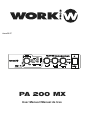
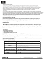
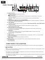
FRONT PANEL
[VOLUME
[MIC INPUT
[POWER
[POWER SWITCH
SIGNAL]
SIGNAL]
]
indicator
indicator
indicator
[VOLUME
LIMIT]
indicator
Lits when input signal exceeds a
It lits when a signal is connected in the mic input terminals placed in the rear panel.
certain level.
Lits if signal output to the speakers exceeds
the limit value, causing the limiter to activate,
or if the internal temperature of the device
tincreases abnormally. If the limiter activates,
turn the [VOLUME] knob to the left so
the indicator light goes out.
[VOLUME]
[LEVEL]
[TREBLE]
[BASS]
[INPUT]
[INPUT 1]
knob
knob
knob
knob
selector
Adjusts the master volume output to the speakers. Turning to the right the volume increases.
Adjusts the selected LINE input volume. Turning to the right the level increases.
Adjusts the high frequencies tone in the output. Turning to the right the tone gain increases.
Adjusts the low frequencies tone in the output. Turning to the right increases the tone gain.
It allows to select the LINE input. INPUT 1 in the front side and INPUT 2 & 3 in the rear panel.
This stereo minijack connector corresponds to INPUT 1. It accept LINE level. NOTE: Without
insert LINE input connector, the Bluetooth function is actived. When you insert a connector,
the Bluetooth function is disabled and operate the LINE input.
Turning all the way to the left mutes the sound.
Turning all the way to the left mutes the sound.
Turning all the way to the left reduces it.
Turning all the way to the left reduces it.
When the device detects signal, the corresponding green LED will lit.
Low-impedance
connections
High-impedance
connections
-17.0dBu or more
-17.0dBu or more
-0.8dBu or more
2.3dBu or more
[VOLUME SIGNAL]
[8Ω]
[16Ω]
[70V]
[100V]
2.
1.
Caution
Turns on when the power is on.
Turn on/off the power.
·To ensure that high-volume noise is not output from the speakers, power on the connected device
first and then turn on this device. When turning the system off, turn off this device, and then the
connected devices.
·After turning the power switch off, wait for about five seconds before turning it on again. Rapidly
turning the power switch on and off in succession can cause the unit to malfunction.
·Even when the switch is in the off position, a small amount of electricity is still flowing to the unit.
If it will not be used for an extended period of time, therefore, be sure to unplug the power cord
from the wall AC outlet.
3.
11.
4.
5.
10.
6.
7.
8.
9.
PA 200 MX
]
2
1
4
5
6
7
8
10
3
9
11
]

4
User Manual / Manual de uso
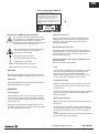
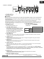
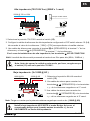
REARPANEL
14
20
15
12
21
13
16
17
18
19
AC
IN connector
Caution
[SPEAKERS]
output terminals
DIP switches
[OUTPUT]
[RS485 input (RJ45 connection)]
[LINE OUT]
[SETUP]
switch
Connect the supplied power cord.
·When connecting the power cord, connect the power cord to the connector and then plug
it into an appropriate AC power outlet.
·Before connecting or disconnecting the power cord, make sure that the power to the
device is turned off.
Barrier strip type speaker output connectors. Refer to “Connecting Speakers” for
the installation instructions.
Sets the output type of amplifier: high-impedance connection ([100V], [70V]) or
It is possible to send RS485 commands from an external device in order to control
low-impedance connection ([8Ω 16Ω]).
several function in the amplifier .
12.
13.
14.
15.
16.
17.
Allows to set some functions (Check DIPSWITCHES FUNCTIONALITY section)
RCA type stereo output jack (unbalanced output). Allows to send preamplified signal
to another amplifier.
EN
G
L
L L
R R R
SPEAKERS
DCP
SETUP
[INPUT 2 & 3]
These stereo RCA connectors (unbalanced) correspond to INPUT 2 & 3. They accept LINE level
18.
[MIC INPUT
SIGNAL]
Terminal block that accepts microphone input level.
19.
[MIC LEVEL]
[BT ANTENNA]
knob
Adjusts the MIC input volume. Turning to the right increases the level.
Bluetooth antenna
20.
21.
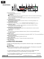
Change the setting depending on the speaker connection (high- or low-impedance
connection).
·Before connecting speakers, make sure that the power of the device is turned off.
If the power is on, there is a risk of electrical shock.
·In a high-impedance installation, make sure that the sum of the power input
ratings of the speakers to be connected does not exceed 200W.
·In a low-impedance installation, make sure that the total impedance of speakers
to be connected is at least 8 ohms.
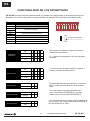
CONNECTING SPEAKERS
CAUTION
PA 200 MX

5
User Manual / Manual de uso
High-impedance (70V/100V line) (200W x 1 channel)
Low-impedance (2x 100W @ )8Ω
2. Set the speaker output to high-impedance by setting the DIP Switch number 10 (14), according
to loudspeakers value [100V] or [70V] corresponding to the maximum output voltage.
3. Use speaker cables to connect the [SPEAKERS A] terminal to the positive “+” terminals
2. Use speaker cables to connect the
3. Use speaker cables to connect the
[SPEAKERS A] , terminals to the +, -
[SPEAKERS B] , terminals to the +, -
of the speakers, and the [SPEAKERS B]
terminals of the loaded speakers,
terminals of the loaded speakers,
terminal to the negative “-” terminals.
In case of high-impedance connection, terminals MUST NOT BE CONNECTED
Note :The speaker output is processed through a high pass filter (80Hz, 18dB/oct.).
Note :Take into account the maximum power loaded per channel (100W @ 8Ω)
Maximum output voltage:100V
Maximum output voltage:70V
8
8
200W @ 70V or 100V
DIP switch body
1. Select 70V/100V position using the switch (15).
1. Select 8 position using the switch (15). Ω/16Ω
100W @ 8Ω
100W @ 8Ω
Note: In low impedance DOES NOT EXIST Bridge mode. Therefore, the
usual bridge connection (using both + terminals), are used ONLY in high
impedance mode.
Note: Before operates the unit in this mode, please, check the switch (15)
position (70/100V position)
EN
SPEAKERS
SETUP
SPEAKERS
SETUP
PA 200 MX

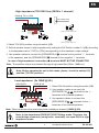
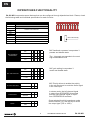
DIPSWITCHES FUNCTIONALITY
PA 200 MX incorporates some features that can be configured through dipswitches block. Please, check
the following table and individual specification for each function.
DIPSWITCH FUNCTION
SW 1 NOT USED
SW 2 NOT USED
SW 3
SW 4
SW 5
SW 6
SW 7 NOT USED
SW 8 MIC PRIORITY STATE
SW 9 STEREO / MONO INPUT
SW 10 70V OR 100V WHEN HIGH IMPEDANCE IS SELECTED
OFF
1st
2nd
3rd
FEEDBACK SUPRESSION
MICROPHONE GAIN SETTING
MIC FEEDBACK
SUPRESSOR
DIP switch body
OFF
+ 6 dB
+ 10 dB
+ 15 dB
MIC GAIN SETTING
DISABLED
ENABLED
MIC INPUT PRIORITY
MONO
STEREO
LOW IMPEDANCE
MODE INPUT
70V
100V
HIGH IMPEDANCE
MODE
MIC feedback supressor incorporates 3
presets and disable state.
The 1st preset corresponds to the most
high antifeedback level
MIC gain setting incorporates 3
levels and disable state.
MIC Priority allows to enable the priority
in the mic input and to mute the audio signal
in the LINE input.
In stereo mode, the left channel signal
is output from SPEAKERS A terminals
and the right channel signal is output
from SPEAKERS B terminals.
Once selected the high impedance mode
with the switch (15), use this dip to select
the output type (70V or 100V).
6
User Manual / Manual de uso
EN
PA 200 MX

Este símbolo, cuando aparece, le alerta
de la presencia de un voltaje peligroso y no
aislado dentro del producto. este voltaje
puede ser suficiente para constituir un riesgo
de descarga eléctrica.
Este símbolo, cuando se use, le alerta de una
instrucción de funcionamiento o seguridad
importante. Por favor, léala
Terminal de protección de toma tierra.
Alimentación AC (Corriente Alterna)
Terminal cargado (peligro)
ON: Denota que el producto está encendido.
OFF: Denota que el producto está apagado.
WARNING
Describe precauciones que deben ser observadas
para prevenir la posibilidad de muerte o daños al
usuario.
CAUTION
Describe precauciones que deben ser observadas
para prevenir daños en el producto.
WARNING
Alimentación
Asergúrese que la toma de alimentación (Toma AC)
es igual a la marcada por el producto. Si no es así
el producto podría dañarse e incluso dañar al usuario.
Desconecte el producto antes de una tormenta
eléctrica y cuando vaya a dejar de usarlo durante
periodos largos de tiempo para reducir el riesgo de
descargas eléctricas.
Conexiones Externas
Utilice siempre el cable de alimentación aislado
suministrado. En caso de no hacerlo, puede incurrir
en un riesgo de descarga eléctrica o fuego. En caso
de duda, consulte a un electricista especializado.
No retire ninguna cubierta
Dentro del producto hay zonas con tensiones altas
presentes. Para reducir el riesgo de descargas
eléctricas no quite las tapas a menos que el cable
AC esté retirado.
Las tapas sólo deben ser retiradas por personal
cualificado.
No hay elementos de control para el usuario en el
interior.
Fusible
Para prevenir fuego y daño en el producto, uso
sólo el tipo de fusible recomendado como indica el
manual. No cortocircuite el portafusible. Antes de
sustituirlo, asegúrese que el producto está apagado
y desconéctelo de la toma AC..
Protección de masa
Antes de encender la unidad, asegúrese que está
conectado a masa. Esto previene el riesgo de descarga
eléctrica.
Nunca corte interna o externamente el cable de masa
Además nunca desconecte el cable del terminal de
masa.
Condiciones de Funcionamiento
Instale la unidad de acuerdo a la instrucciones del
fabricante.
para evitar el riesgo de descargas eléctricas y daños, no
someta al producto a ningún líquido, lluvia o humedad.
No use el producto cerca del agua.
No instale este producto bajo la luz solar directa.
No bloquee las salidas de ventilación.
SÍMBOLOS RELATIVOS A LA SEGURIDAD
EXPLICACIÓN DE LOS SÍMBOLOS GRÁFICOS
TO REDUCE THE RISK OF FIRE OR
ELECTRIC SHOCK, DO NOT EXPOSE
TO RAIN OR HUMIDITY. DO NOT
REMOVE COVER. THIS PRODUCT IS
NOT INTENDED FOR USE OTHER THAN
STATED.
WARNING:
7
User Manual / Manual de uso
ES
PA 200 MX

NOTAS DE INSTALACIÓN
En todo momento, el amplificador tiene que ser manejado bajo condiciones apropiadas. Esto incluye que la
ubicación proporcione una ventilación suficiente y el aparato no esté expuesto a la luz solar directa, radiación
o reflexión a partir de cualquier fuente de calor. Al instalar un sistema de altavoces debe elegir una ubicación
que no se vea afectada por las vibraciones extremas y / o constante o de la oscilación mecánica. también
asegúrese de que los altavoces están instalados en lugares que están libres de polvo y/o humedad.
PRECAUCIÓN
Evite el riesgo de choque eléctrico. Para reducir el riesgo de choques eléctricos, todas las conexiones tienen que
realizarse antes de conectar el amplificador a la alimentación principal. Asegúrese que todas las conexiones se
realizan correctamente y que no existen cortocircuitos. La instalación de sonido en general tiene que ser de
acuerdo a las leyes, reglamentos, normas y directrices pertinentes y aplicables en el país en el que el equipo va
a ser operado.
PRECAUCIÓN CON LA ALIMENTACIÓN AC
Antes de utilizar el amplificador por primera vez, asegúrese que la tensión del aparato es conforme a
su red eléctrica. Conecte el amplificador a tierra sólo en tomas de red. Conexión del amplificador a
alimentación de la red (100-240Vac) tiene que llevarse a cabo mediante la inserción del cable de alimentación
suministrado en la toma correspondiente y luego conectarlo a una toma de corriente.
8
User Manual / Manual de uso
DESCRIPCION
PA 200 MX es un amplificador de instalación que incorpora 3 entrada LINE (LINE 1 con funcionalidad
propio, 2 controles de tono y LEDs que marcan la presencia de señal
amplificador incorpora entrada de micrófono, proporcionando función de
características para configurar el sistema de acuerdo a los requerimientos de
l
Las funciones a configurar son:
- Prioridad MIC
- Modo de entrada stereo/mono
- 3 niveles de ganancia MIC
- 3 presets anti-feedback para la entrada MIC
PA 200 MX puede funcionar tanto en baja impedancia como con altavoces de línea 70/100V.
El modo de funcionamiento se selecciona mediante un switch en el panel trasero y un bloque de
dipswitches, el cual dispone de algunos terminales reservados para futuras mejoras.
En la parte trasera, el amplificador incorpora una toma RJ45, la cual admite comandos RS485 desde
un dispositivo externo para el control de varias funciones del amplificador.
BLUETOOTH) con selector y volumen
y el modo limit. Adicionalmente, el
mezclador y añadiendo varias
a instalación.
Potencia de salida 2x 100W @ 8Ω / 200W (70/100V Line)
Entradas de audio 2 LINE (desbalanceadas), 1 MIC, 1 RJ45 (comandos RS485)
THD +N
Respuesta en frecuencia 20 Hz-20kHz 0dB - 0.5dB
Alimentación AC 100-240 V - 50/60Hz
Dimensiones 215x48x264mm(AnxAlxPr)
Peso 2.3 kg.
ESPECIFICACIONES TECNICAS
ES
PA 200 MX
1 kHz, 15W, 8Ω/16Ω 0,1%
1 kHz, 30W, 70V/100V 0,2%
≥
≥

9
User Manual / Manual de uso
PANEL FRONTAL
[VOLUME
[POWER
[INTERRUPTOR DE RED
SIGNAL]
]
]
Indicador
Indicador
Indicador
[VOLUME
LIMIT]
Se enciende cuando la señal de
entrada excede cierto nivel.
[VOLUME]
conexiones
baja impedancia
conexiones
alta impedancia
-17.0dBu o más
-17.0dBu o más
-0.8dBu o más
2.3dBu o más
[VOLUME SIGNAL]
[8Ω]
[16Ω]
[70V]
[100V]
2.
1.
Precaución
Se enciende cuando la unidad está conectada
Enciende/apaga el amplificador
3.
4.
5.
- Para asegurar que no se producen ruidos elevados en los altavoces, encienda los dispositivos
conectados a este amplificador y, finalmente, el amplificador. A la hora de apagar las unidades
proceda en sentido inverso (primero el amplificador).
-Después de apagar la unidad, espérese unos 5 segundos antes de volver a encender. El apagar
o encender de manera repetitiva puede causar mal funcionamiento en el amplificador.
- Incluso apagado, existe una pequeña cantidad de electricidad fluyendo por la unidad. Si no va a
usar la unidad durante largo tiempo, asegúrese de desconectarla de la base mural.
Se ilumina cuando la señal en la salida de los
altavoces supera un cierto umbral, causando
que el limitador se active. También se ilumina
si la temperatura interna aumenta de manera
inusual. Si se activa el limitador, reduzca el nivel de volumen hasta conseguir apagar el LED
Ajusta el volumen master del amplificador. Girando a la derecha se incrementa el volumen,
girando a la izquierda se reducir hasta conseguir "mutear" la salida.
ES
[MIC INPUT
SIGNAL]
Se ilumina cuando se conecta una señal en los terminal MIC del panel trasero.
[LEVEL]
[TREBLE]
[BASS]
[INPUT]
[INPUT 1]
selector
Ajusta el nivel de la señal LINE seleccionada con el selector (8) Girando a la derecha se incrementa
Ajusta las frecuencias agudas en la salida. Girando a la derecha se incrementa el nivel.
Ajusta las frecuencias graves en la salida. Girando a la derecha se incrementa el nivel.
Permite seleccionar las entrada LINE. INPUT 1 en el frontal e INPUT 2 y 3 en el panel trasero.
Este conector estéreo minijack corresponde a INPUT 1. Acepta señal LINE. NOTA: Si no se
conecta ningún conector a esta toma, se activa la función Bluetooth. Al insertar un conector,
se activa la entrada LINE.
el nivel. Girando a la izquierda se reduce.
Girando a la izquierda se reduce
Girando a la izquierda se reducir
Cuando el dispositivo detecta señal, se enciende el LED verde correspondiente.
11.
10.
6.
7.
8.
9.
PA 200 MX
2
1
4
5
6
7
8
10
3
9
11
]

PANEL TRASERO
Conector AC IN
Precaución
Terminales de salida de altavoces[SPEAKERS]
DIP switches
[Entrada RS485 (conexión RJ45)]
[LINE OUT]
Switch de modo
Conecte el cable de alimentación incluido
·Cuando conecte el cable de alimentación, conecte primero al amplificador y, finalmente
a la toma mural AC.
·Antes de conectar o desconectar la unidad, asegúrese que el amplificador está
apagado.
Bloque de terminales para el conexionado de los altavoces. Diríjasa al apartado “Conectando
los altavoces” para las instrucciones.
Configura el tipo de conexionado de salida: Alta impedancia ([100V], [70V]) o
Es posible enviar comandos RS485 desde un dispositivo externo para controlar varias
baja impedancia ([8Ω 16Ω]).
funciones en el amplificador.
12.
13.
14.
15.
16.
17.
Permiten configurar varias opciones (Compruebe FUNCIONALIDAD DE LOS DIPSWITCHES)
Conectores de salidada estéreo RCA (salida desbalanceada). Permite enviar señal
preamplificada a otro amplificador.
10
User Manual / Manual de uso
ES
[INPUT 2 y 3]
Estos conectores estéreo RCA (desbalanceados) corresponden a INPUT 2 y 3. (Nivel LINE)
18.
[MIC INPUT
SIGNAL]
Bloque de terminales que acepta señal de micrófono.
19.
[MIC LEVEL]
Ajusta el volumen de la entrada MIC. Gire a la derecha para incrementar el volumen
20.
CONECTANDO LOS ALTAVOCES
Cambie la configuración dependiendo del conexionado de los altavoces (alta o baja impedancia).
CAUTION
- Antes de conectar los altavoces, asegúrese que la alimentación del dispositivo está apagada. Si está
encendida hay riesgo de descarga.
- En instalaciones de alta impedancia, asegúrese que la suma de la potencia de todos los altavoces
conectados no excede los 200W.
- En instalaciones de baja impedancia, asegúrese que la impedancia total de los altavoces conectados
no es menor de 8 ohmios.
PA 200 MX
14
20
15
12
21
13
16
17
18
19
G
L
L L
R R R
SPEAKERS
DCP
SETUP
[BT ANTENNA]
antena Bluetooth
21.

Alta impedancia (70V/100V line) (200W x 1 canal)
Baja impedancia (2x 100W @ )8Ω
2. Configure la salida de altavoces de alta impedancia configurando el DIP swtich número 10 (14),
tde acuerdo al valor de los altavoces [100V] o [70V] correspondiente a la salida máxima.
3. Use cables de altavoz para conectar el terminal de [SPEAKERS A] al terminal “+” de los
2. Use cables de atavoz para conectar los
3. Use cables de atavoz para conectar los
terminales [SPEAKERS A] a los terminales
terminales [SPEAKERS B] a los terminales
altavoces y el terminal de [SPEAKERS B]
+ y - de los altavoces cargados en el 1º canal.
+ y - de los altavoces cargados en el 2º canal.
al terminal “-” de los altavoces.
En el caso de instalaciones de alta impedancia, los terminales NO SE CONECTAN
NotA :La salida de altavoz está procesada a través de un filtro paso alto (80Hz, 18dB/oct.).
Nota :Tenga en cuenta que la potencia máxima cargada por canal es de (100W @ 8Ω)
Salida máxima:100V
Salida máxima:70V
8
8
Cuerpo del DIP switch
1. Seleccione la posición 70V/100V usando el switch (15).
1. Seleccione la posición 8 usando el
switch (15).
Ω/16Ω
Nota:En baja impedancia NO EXISTE el modo Bridge. Así pues, el
conexionado bridge usual (usando ambos terminales +), se usa
UNICAMENTE en modo alta impedancia.
Nota: Antes de operar la unidad en este modo, por favor, asegúrese que
el switch (15) está en la posición 70/100V .
11
User Manual / Manual de uso
ES
200W @ 70V or 100V
SPEAKERS
SETUP
100W @ 8Ω
100W @ 8Ω
SPEAKERS
SETUP
PA 200 MX

12
User Manual / Manual de uso
ES
PA 200 MX
FUNCIONALIDAD DE LOS DIPSWITCHES
PA 200 MX incorpora algunas características que pueden ser configuradas a través de este bloque de
dipswitches. Por favor, compruebe la siguiente tabla y la especificación individual para cada función.
DIPSWITCH FUNCION
SW 1 SIN USO
SW 2 SIN USO
SW 3
SW 4
SW 5
SW 6
SW 7 SIN USO
SW 8 PRIORIDAD MIC
SW 9 ENTRADA STEREO / MONO
SW 10
70V O 100V CUANDO SE SELECCIONAL ALTA IMPEDANCIA
OFF
1st
2nd
3rd
SUPRESION FEEDBACK
CONFIGURACION DE GANANCIA MC
SUPRESION
FEEDBACK
Cuerpo del DIPswitch
OFF
+ 6 dB
+ 10 dB
+ 15 dB
GANANCIA MIC
DISABLED
ENABLED
PRIORIDAD MIC
MONO
STEREO
ENTRADA ST/MONO
BAJA IMPEDANCIA
70V
100V
MODO
ALTA IMPEDANCIA
MIC supresor feedback incorpora 3 presets y
estado de desconexión.
El 1º preset corresponde al nivel de supresión
más alto.
La configuración de ganancia MIC incorpora 3
niveles y estado de desconexión.
Prioridad MIC permite dar prioridad a la entrada
MIC y mutear la señal de audio de la entrada
LINE.
En modo estéreo, la señal izquierda sale
por los terminales SPEAKERS A y la señal
derecha por los terminales SPEAKERS B.
Una vez seleccionado el modo de alta impedancia
con el switch (15), use este dip para seleccionar el
tipo de salida(70V o 100V).


EQUIPSON, S.A.
Avda. El Saler, 14 - Pol. Ind. L´Alteró,
46460 - Silla (Valencia) Spain
Tel. +34 96 121 63 01 Fax + 34 96 120 02 42
www.workproaudio.com [email protected]
-
 1
1
-
 2
2
-
 3
3
-
 4
4
-
 5
5
-
 6
6
-
 7
7
-
 8
8
-
 9
9
-
 10
10
-
 11
11
-
 12
12
-
 13
13
-
 14
14
-
 15
15
-
 16
16


Work-pro PA 200 MX Manual de usuario
- Categoría
- Amplificadores de audio
- Tipo
- Manual de usuario
en otros idiomas
- English: Work-pro PA 200 MX User manual