Orion CO552 El manual del propietario
- Categoría
- Altavoces de coche
- Tipo
- El manual del propietario
Este manual también es adecuado para

Component
Speaker
MODEL
CO552
CO652
OWNER'S
MANUAL


© 2012 MD Audio Engineering—all rights reserved
1
Table Of
Con
t
en
t
s
english
. . . . . . . . . . . . . . . . . . . . . . . . . . . . . . . . . . . . . . . . . . . . . . . .
1
français
. . . . . . . . . . . . . . . . . . . . . .
.
. . . . . . . . . . . . . . . . . . . .
9
español
.
.
. . . . . . . . . . . . . . . . . . . . . . . . . . . . . . . . . . . . . . . .
13
Deutsch
. . . . . . . . . . . . . . . . . . . . . . . . . . . . . . . . . . . . . . . . . .
17
Italiano
. . . . . . . . . . . . . . . . . . . . . . . . . . . . . . . . . . . . . . . . . .
21
Português
. . . . . . . . . . . . . . . . . . . . . . . . . . . . . . . . . . . . . . . . .
25
Introduction
. . . . . . . . . . . . . . . . . . . . . . . . . . . . . . . . . . . . . . . . . . . . . .
1
Practice
safe
s
ound™
. . . . . . . . . . . . . . . . . . . . . . . . . . . . . . . . . . . . . . . .
1
What’s in the box
. . . . . . . . . . . . . . . . . . . . . . . . . . . . . . . . . . . . . . . . . .
2
Installing Process
. . . . . . . . . . . . . . . . . . . . . . . . . . . . . . . . . . . . . . . . . . .
2
Tools of the Trade
. . . . . . . . . . . . . . . . . . . . . . . . . . . . . . . . . . . . . . . . . .
2
finding speaker
Mounting
l
ocations
. . . . . . . . . . .
.
. . . . . . . . . . . . . . . . . . . .
2
Door Mounting
. . . . . . . . . . . . . . . . . . . . . . . . . . . . . . . . . . . . . . . . . . .
3
Rear Deck Mounting
. . . . . . . . . . . . . . . . . . . . . . . . . . . . . . . . . . . . . . . . .
3
Installing the Mid/Woofers
. . . . . . . . . . . . . . . . . . . . . . . . . . . . . . . . . . . . . .
4
Installing the Tweeter
. . . . . . . . . . . . . . . . . . . . . . . . . . . . . . . . . . . . . . . .
5
Installing the Crossover
. . . . . . . . . . . . . . . . . . . . . . . . . . . . . . . . . . . . . . .
6
Wiring Diagram
. . . . . . . . . . . . . . . . . . . . . . . . . . . . . . . . . . . . . . . . . . . .
7
s
pecifications
. . . . . . . . . . . . . . . . . . . . . . . .
.
. . . . . . . . . . . . . . . . . . . .
8
f
eatures
. . . .
.
. . . . . . . . . . . . . . . . . . . . . . . . . . . . . . . . . . . . . . . . . . .
8
Warranty
. . . . . . . . . . . . . . . . . . . . . . . . . . . . . . . . . . . . . . . . . .
back cover
In
tr
o
d
u
cti
on
Thank you for your purchase of the
orion
TM
Cobalt Component
l
oudspeaker system
.
These
speakers represent a combination of incredible performance and value
.
The
orion
TM
stamped
steel frame components feature treated paper cones and metalized PeI (Polyetherimide)
tweeters
.
Capable of maintaining their balance and clarity at exceptionally high output levels,
they are the perfect complement to the
orion woofers
.
The crossovers feature tweeter level
adjustment
.
The components are available in standard 5-1/4" and 6-1/2" sizes to fit most
applications
.
We at
orion
TM
strive to give you all the latest up to date information about this product
.
What we can't give you in this manual is personal installation or technical experience
.
If you
have questions concerning the use or application of this product, please refer to the nearest
a
uthorized
oRIon
TM
Dealer for assistance or call the
orion
TM
technical support hotline at 1-
800-876-0800
.
as
we are always finding new ways to improve our product, the features and
specifications are subject to change without notice
.
Pr
a
ctice
Safe
S
oun
d™
Continuous exposure to sound pressure levels over 100db may cause permanent hearing loss
.
High powered automotive sound systems can generate sound pressure levels in excess of 130d
b .
When playing your system at high levels, please use hearing protection and prevent long term
exposure
.

2
© 2012 MD Audio Engineering—all rights reserved
Model
n
umber:
serial
n
umber:
Date of Purchase:
What’s
In The B
ox
Included in this box are all the necessary mounting hardware and cables for your basic
installation
.
l
isted below is a detailed list of the components included in this system package
.
Quantity Description
1 Installation and
operation
Manual
2
orion
TM
Tweeter elements
2
surface
mount hardware
2
flush
mount hardware
2
orion
TM
mid/woofer speakers
2 Passive crossovers with cables
1 Mounting template
2 Grills
Mounting screws
Ins
t
all
i
n
g Pr
o
c
ess
The performance of the
orion
TM
Component
l
oudspeaker is directly proportional to the
quality of installation
.
Care taken during the installation process will be rewarded with years
of satisfying performance
.
If you are unsure about your installation capabilities, please refer
to your local
a
uthorized
orion
TM
Dealer for technical assistance
.
orion
TM
dealers are trained
professionals dedicated to extracting the maximum performance out of your
orion
TM
system
.
If you decide to install this speaker system yourself, please read the entire installation section
before starting your installation
.
Tools Of
The Tr
a
de
l
isted are the majority of the tools required to perform the installation
.
Having the proper tools
will make the installation much easier
.
It is very difficult when you get half way through the
installation and discover that you require a specific tool to get yourself through a particular part
of the installation
.
some
of these tools are necessities
.
some
make the job much easier
.
o Marking Pen o electric Drill
o 1/4" Drill bit o Phillips
s
crewdriver
o 1/8" Drill bit o
Volt/ohm
Meter (
o
ptional)
o 3/8" Drill bit o needle nose Pliers
o Hole
saw arbor
o
assorted
Tin
s
nips
o Wire Crimpers o Wire
s
trippers
o 4-3/4" Hole
saw
(5-1/4" mid/woofer install
.
)
o 5-5/8" Hole
saw
(6-1/2" mid/woofer install
.
)
o 1-7/8"Hole
saw
(for flush mount tweeter installation
.
)
Finding
Speaker Mounting
L
o
c
a
ti
ons
Choosing the correct speaker locations will have the greatest effect on the sound quality of the
system
.
Different considerations are needed when choosing the locations that best suit your

© 2012 MD Audio Engineering—all rights reserved
3
needs
.
The locations must be large enough for the speakers to fit
.
Care is needed to ensure that
the location you have chosen will not affect any of the mechanical or electrical operations of
the vehicle
.
Determining the best location for the speakers will depend on your cosmetic needs and your
vehicle's interior
.
If minimal intrusion in your vehicle is desired, factory speaker locations may
be the ticket for you
.
Placing the speaker in the factory location can often give very desirable
results
.
Door
Moun
ti
n
g
When checking for possible speaker locations in the doors, check the operation of the window
and all assemblies
.
There is also a stabilizer stop bar in between the door and the door jamb
.
This bar prevents the door from opening too far
.
Many shade tree installers overlook this and
check for clearance only when the door is fully open
.
figure
1
figura
1
a
bbildung 1
Inside
of
Door
Speaker
installed
with no
gaps
or air
leaks
Dampening
on
top of
outer
door
skin
Speaker
cut
out
Door
Panel
Dampening
Mat
Coaxial
Driver
Grille
Screws
Rear Deck
Moun
ti
n
g
In rear deck installations, check the operation of the trunk suspension springs or tension bars
.
These tension bars move in the opening and closing of the trunk
.
You cannot be too cautious
during this part of the installation, In addition, do not locate the speakers too close to the back
of the rear deck
.
Installing the far screws will only be possible with the removal of the rear
window
.
figure
2
figura
2
a
bbildung 2
Rear Seat
Rear/Trunk
of Car

4
© 2012 MD Audio Engineering—all rights reserved
Ins
t
all
i
n
g The Mid
/Woofe
r
s
step
1: Determine where the speakers will be mounted
.
Make sure there is a flat area large
enough for the speakers to fit properly
.
an
uneven mounting surface can damage the
driver
.
step
2: Check to make sure the space you have chosen for the speakers will not interfere with
the operation of the vehicle
.
step
3: using the supplied template guide, mark the mounting hole and mounting screw hole
locations with a pen for each speaker
.
step
4: Cut the holes for the speaker
.
When using correctly sized factory locations, this step
can be passed
.
a
hole can be cut either with a pair of metal tin snips, an air or jig saw,
or with a hole saw corresponding to the size of the midrange listed below
.
o 4-3/4" Hole
saw
(5-1/4" woofer installation)
o 5-5/8" Hole
saw
(6-1/2" woofer installation)
WARNING: Check for clearance of window mechanisms and electrical wires befoRe you drill
.
step
5: Run the speaker wire to the speakers
.
Make sure to keep wires away from sharp metal
or other edges
.
When passing through metal, use a protective grommet
.
step
6: Pre-drill mounting screw holes using a 1/8" drill bit
.
WARNING: Check for clearance of window mechanisms and electrical wires befoRe you drill
.
step
7: Pull the wire through the speaker opening and connect to the speaker
.
be sure to
observe proper mid/woofer polarity during this process
.
step
8: Mount the speaker- Place the speaker and the grille in the installation hole
.
align
the
mounting screw holes and drive in the four mounting screws
.
figure
3
figura
3
a
bbildung 3
Panel
Wiring
Harness

© 2012 MD Audio Engineering—all rights reserved
5
Ins
t
all
i
n
g The Tweeter
suRfaCe M
oun
TI
n
G
step
1: Determine the tweeter mounting location, then route the wires from the crossover to
the tweeter location
.
step
2: Place the provided template or tweeter cup against the panel and mark the two holes
at the rear of the housing
.
step
3: Drill the smaller holes using a 1/8" drill bit
.
These are the mounting screw holes
.
WARNING: Check for clearance of window mechanisms and electrical wires befoRe you drill
.
step
4: Drill the larger off-center hole using a 3/8" drill bit, insert a grommet and route the
speaker wire from the crossover through the grommet
.
step
5:
after
removing the surface mount tweeter assembly trim ring, route the tweeter wires
through the larger hole in the housing and connect to the speaker wires from the
crossover
.
(see figure 4
.
)
step
6: Insert the excess speaker wire into the hole and position the housing so the housing
will not pinch the wires after final mounting
.
step
7:
attach
the housing using the supplied screws of the correct length for a solid mount
.
step
8: Insert the tweeter into the housing and attach the surface mount trim ring
.
Surface
Mount
Trim Ring
Mounting
Screws
Surface Mount Housing
figure
4
figura
4
a
bbildung 4
Tweeter
Tweeter
Wire
Panel
Wiring
Harness
full
flus
H M
oun
TI
n
G
step 1:
.
Determine where the tweeter will be mounted
.
Make sure there is a flat area large
enough for the tweeter and no obstructions behind the area
.
step
2: using the back half of the tweeter housing, mark with a pen the hole needed for the
tweeter
.
step
3: be sure the hole is large enough for the tweeter housing, but not so large that the
flange will not cover the hole
. .
step
4: Cut the hole for the tweeter
.
When using factory locations, this step can be skipped
.
a
hole can be cut either with a pair of metal tin snips or a 1-7/8" hole saw for hard
materials
.
WARNING: Check for clearance of window mechanisms and electrical wires befoRe you drill
.

6
© 2012 MD Audio Engineering—all rights reserved
step
5: Install tweeter in flush mount housing
.
step
6: Connect the speaker wires observing the correct polarity
.
step
7: Install tweeter and housing in the hole cut for mounting, so that the trim ring is flat
with the front of the surface
.
step
8: use the supplied pressure ring to secure the housing to the surface
.
Flush
Mount
Tweeter
Assembly
Tweeter
Cup
Pressure
Ring
figure
5
figura
5
a
bbildung 5
Flush Mount
Trim Ring
Tweeter
Wire
Panel
Wiring
Harness
Ins
t
all
i
n
g The Cr
osso
ver
step
1:
find
a location for the crossover away from any factory or after market electrical wires
.
It is recommended to mount the passive crossover close to the amplifier
.
step
2: Mount the crossover using the supplied wire ties
.
step
3: Connect the wires
.
Make sure the speaker wires for the midrange go to the mid/
woofer output and the tweeter to the tweeter output
.
be sure to observe the correct
polarity
.
Changing the polarity of the tweeter may be necessary for optimum sound
quality
.

© 2012 MD Audio Engineering—all rights reserved
7
Wiring Di
a
gr
a
m
Input
To Amplifier
Output
+
_
To woofer +
_
To tweeter
+
_
Note: The tweeter positive is the wire marked with the stripe.
Note: Le câble positif du haut-parleur d'aigus est rayé.
Nota. El positivo del tweeter es el cable que tiene la franja.
Hinweis: Der positive Hochtönerdraht ist mit dem Streifen markiert.
Nota: il filo positivo del tweeter è contrassegnato da una striscia.
Nota: O cabo positivo do tweeter está marcado com a listra.
figure
6
figura
6
a
bbildung 6

CO552
CO652
Dimensions inches/mm, Dimensions pouces/mm,
Dimensiones plg
.
/mm,
a
bmessungen Zoll/mm,
Dimensioni pollici/millimetri, Dimensões
polegadas/mm
a
1
.
97/50
2
.
36/60
b
0
.
71/18
0
.
91/23
C
2
.
76/70
3
.
15/80
D
4
.
72/120
5
.
63/143
e
5
.
12/130
6
.
50/165
Sp
eci
f
ic
a
ti
ons
Model/Part number
C
o
552
C
o
652
nominal Impedance
4 ohm
4 ohm
Power Continuous/Maximum
40 /100 w
50 /120 w
f
requency Response
120 -20kHz
60 - 20kHz
s
ensitivity
87db
85db
Mounting Depth
1
.
97"/50mm
2
.
36"/60mm
Mounting Diameter
4
.
72"/120mm
5
.
63"/143mm
f
ea
T
u
R
es
Cone
moisture and uV resistant paper cone
s
urround
nbR (nitrile butadiene rubber)
Voice Coil
2 layer copper clad aluminum wire on a kapton former
Tweeter
metalized PeI (Polyetherimide) -
f
errofluid
s
pider
single interlaced Conex
s
tamped steel baskets with euro mounting configurations
Two way systems have custom crossover with 6 db high pass, 6 db low pass and tweeter
protection
swivel
tweeter
noTe:
all
s
pecifications are subject to change without notice
.
A
B
figure
7
C
figura
7
D
a
bbildung 7
E
F
G
8 © 2012 MD Audio Engineering—all rights
reserved

H


© 2012 MD Audio Engineering—all rights
9
F
r
an
ç
a
i
s
Où
monter
les h
au
t-p
a
r
leu
r
s
l
e choix du bon emplacement des haut-parleurs aura un effet majeur sur la qualité du son du
système
.
Plusieurs choses doivent être prises en considération pour faire le meilleur choix
.
l
es
emplacements doivent être assez grands pour accueillir les haut-parleurs
.
faites
attention que
l'emplacement choisi n'affecte en aucune façon le fonctionnement mécanique et électrique du
véhicule
.
l
e meilleur emplacement pour les haut-parleurs dépend de vos goûts et de l'aménagement
intérieur du véhicule
.
si
vous voulez une installation aussi discrète que possible, les emplacements
prévus par le fabricant sont sans doute le meilleur choix
.
Cela donnera souvent d'excellents
résultats
.
Montage
Sur Une P
o
rtière
Quand vous recherchez une location possible pour installer vos haut-parleurs dans les portières,
vérifiez le fonctionnement de la fenêtre et de tous les mécanismes
.
Vérifiez aussi la barre
stabilisatrice entre la portière et son montant
.
elle empêche la portière de s'ouvrir trop grand
.
beaucoup d'installateurs inexpérimentés négligent ce détail et ne vérifient l'espace libre que
quand la porte est grand ouverte (figure 1)
.
Montage Dans Le C
off
re
Pour une installation dans le coffre, vérifiez le fonctionnement des ressorts de suspension ou
barres de tension du coffre
.
Ces barres se déplacent durant l'ouverture et la fermeture du coffre
.
on
n'est jamais trop prudent durant cette partie de l'installation
.
De plus, ne placez pas les haut-
parleurs trop près de l'arrière du coffre
.
l
'installation des vis les plus écartées n'est possible que
si on retire la vitre arrière (figure 2)
.
I
n
s
t
a
lla
ti
on
des haut-parleurs médiaux
et de
Gr
a
v
es
Étape 1: Décidez où fixer les haut-parleurs et assurez-vous qu'il y ait une surface plane suffisante
pour bien les fixer
.
une surface de montage inégale peut endommager le moteur
.
Étape 2:
a
ssurez-vous que l'emplacement choisi pour les haut-parleurs n'interfère pas avec le
fonctionnement du véhicule
.
Étape 3:
au
moyen du gabarit de montage fourni et d'un crayon, marquez l'emplacement des
trous de montage et des vis de montage pour chaque haut-parleur
.
Étape 4: Découpez les trous pour le haut-parleur
.
si
vous utilisez les emplacements prévus par le
fabricant et qu'ils sont de la bonne dimension, cette étape peut être sautée
.
u
tilisez
soit une paire de cisailles à tôles, une scie pneumatique ou sauteuse, ou une scie-cloche
de la taille correspondant à celle ci-dessous
.
o
s
cie-cloche 4-3/4" (installation d'un haut-parleur de graves de 5-1/4")
o
s
cie-cloche 5-5/8" (installation d'un haut-parleur de graves de 6-1/2")

10
© 2012 MD Audio Engineering—all rights
aTTenTIon:
Vérifiez l'espace libre du mécanisme et des fils électriques des fenêtres
aVanT
de
percer
.
Étape 5:
amenez
les câbles à leurs haut-parleurs
.
a
ssurez-vous de les garder loin de tout bord
métallique ou autre aiguisé
.
Pour passer à travers le métal, utilisez une rondelle
isolante
.
Étape 6: Pré-percez les trous de vis de montage avec une mèche 1/8"
.
aTTenTIon:
Vérifiez l'espace libre du mécanisme et des fils électriques des fenêtres
aVanT
de
percer
.
Étape 7:
faites
passer le câble par l'ouverture du haut-parleur et raccordez-le
.
a
ssurez-vous de
respecter la polarité du haut-parleur médial et de graves
.
Étape 8: Montez le haut-parleur — Placez-le avec sa grille dans le trou d'installation
.
alignez
les
trous des vis de montage et vissez les quatre vis
.
I
ns
t
alla
ti
on
Du
Haut-Parleur D'
a
ig
us
MonTaGe
en
su
R
f
a
Ce
Étape 1: Décidez où fixer le haut-parleur d'aigus, puis amenez-y les câbles du répartiteur
.
Étape 2: Placez le gabarit fourni ou le cône du haut-parleur d'aigus sur le panneau et marquez
les deux trous à l'arrière du logement
.
Étape 3: Percez les petits trous avec une mèche 1/8"
.
Ce sont les trous de montage
.
aTTenTIon:
Vérifiez l'espace libre du mécanisme et des fils électriques des fenêtres
aVanT
de
percer
.
Étape 4: Percez le grand trou excentré (mèche de 3/8"), insérez une rondelle isolante et faites-y
passer le câble du haut-parleur vers le répartiteur
.
Étape 5: Ôtez la garniture de montage en surface, passez les câbles du haut-parleur d'aigus
par le grand trou du logement et raccordez aux câbles de haut-parleur du répartiteur
(figure 4
.
)
Étape 6: Insérez le câble de haut-parleur en trop dans le trou et placez le logement afin qu'il ne
pince pas les câbles après le montage final
.
Étape 7: Pour un montage solide, utilisez les vis fournies de la bonne longueur pour attacher le
logement
.
Étape 8: Insérez le haut-parleur d'aigus dans le logement et attachez la garniture
.
MonTaGe en
C
as
TRÉ
Étape 1: Décidez où fixer le haut-parleur d'aigus et assurez-vous qu'il y ait une surface plane
suffisante pour bien le fixer, sans obstructions à l'arrière de la surface
.
Étape 2: Marquez le trou de montage nécessaire à l'aide d'un crayon et de la moitié arrière du
logement du haut-parleur
.
Étape 3:
a
ssurez-vous que le trou est assez grand pour le logement du haut-parleur, mais pas trop
grand pour être couvert par la flasque
.
Étape 4: Coupez le trou du haut-parleur (inutile si vous utilisez les emplacements prévus par
le fabricant)
.
utilisez des cisailles à tôles ou une scie-cloche 1-7/8" pour les matériaux
durs
.
aTTenTIon:
Vérifiez l'espace libre du mécanisme et des fils électriques des fenêtres
aVanT
de
percer
.
Étape 5: Installez le haut-parleur dans le logement encastré
.
Étape 6: Raccordez les câbles du haut-parleur en respectant la polarité
.

© 2012 MD Audio Engineering—all rights
1
Étape 7: Installez le haut-parleur et le logement dans le trou découpé pour le montage, afin que
la garniture soit au niveau de l'avant de la surface
.
Étape 8: utilisez l'anneau de pression inclus pour fixer le logement à la surface
.
I
ns
t
alla
ti
on
Du Rép
a
rtit
eu
r
Étape 1: Décidez où fixer le répartiteur, loin de tout fil électrique, d'origine ou installé après
coup
.
l
e répartiteur passif devrait être monté à proximité de l'amplificateur
.
Étape 2: Montez le répartiteur avec les fils d'attache métalliques
.
Étape 3: Raccordez les câbles
.
a
ssurez-vous que les câbles du haut-parleur médial vont à la sortie
médial/graves et ceux du haut-parleur d'aigus à la sortie des aigus
.
a
ssurez-vous de
respecter la polarité
.
Changer celle du haut-parleur d'aigus peut être requis pour une
qualité sonore optimale
.
noTe: Diagramme de référence aux pages 4 - 7 (figure 3, 4, 5, 6)
S
péci
f
ic
a
ti
ons
Modèle/ numéro de pièce
C
o
552
C
o
652
Impédance nominale
4 ohm
4 ohm
Puissance continue/maximum
40 /100 w
50 /120 w
Réponse de fréquence
120 -20kHz
60 - 20kHz
s
ensitivité
87db
85db
Profondeur de montage (pouces/mm)
1
.
97"/50mm
2
.
36"/60mm
Diamètre de montage (pouces/mm)
4
.
72"/120mm
5
.
63"/143mm
C
a
r
a
cteri
s
tiq
ues
Cône
Papier résistant à l'humidité et aux ultraviolets
boîtier
n
itrile
bobine acoustique
fil
d'aluminium recouvert de 2 couches de cuivre sur manchon
k
apton
Haut-parleur d'aigus
Polyétérimide métallisé - ferrofluide
anneau
de centrage
Conex simple entrelacé
Paniers en acier matricé avec configuration de montage européen
s
ystèmes bidirectionnels avec répartiteur personnalisé: passe-haut 6 db, passe-bas 6 db et
protection du haut-parleur d'aigus
Haut-parleur d'aigus orientable
noTe: Toutes spécifications sujettes à changement sans préavis
.


© 2012 MD Audio Engineering—all rights
13
Es
p
a
ñ
ol
Ubicaciones
De
montaje
De
los
al
t
a
v
o
c
es
escoger la ubicación correcta de los altavoces tendrá el mayor efecto en la calidad del sonido
del sistema
.
es necesario que usted tenga en cuenta varias consideraciones cuando escoja el
lugar que mejor se adapte a sus necesidades
.
l
os lugares escogidos deben ser lo suficientemente
grandes como para que quepan los altavoces
.
es necesario que en la ubicación escogida no se
afecte ninguna operación mecánica o eléctrica del vehículo
.
Determinar la mejor ubicación de los altavoces depende de sus necesidades cosméticas y del
interior del vehículo
.
si
desea interferir lo menos posible con el vehículo, las ubicaciones de
altavoz de fábrica son ideales
.
Colocar el altavoz en la ubicación de fábrica puede a menudo dar
muy buenos resultados
.
Montaje
En
La P
ue
rt
a
Cuando esté buscando posibles ubicaciones de altavoz en las puertas, verifique el funcionamiento
de las ventanas y de todos los mecanismos de las puertas
.
También hay una barra de tope
estabilizadora entre la puerta y la jamba de la puerta
.
esta barra evita que la puerta se abra
demasiado
.
Muchos instaladores informales olvidan esto y verifican que haya espacio sólo
cuando la puerta está completamente abierta (figura 1)
.
Montaje
En
La
Repisa Tr
ase
r
a
en las instalaciones en repisa trasera, verifique el funcionamiento de los resortes de suspensión o
barras de tensión de la tapa del maletero
.
estas barras de tensión se mueven cuando se abre o se
cierra el maletero
.
ser
precavido nunca está de más durante esta parte de la instalación
.
a
demás,
no ubique los altavoces demasiado cerca del fondo de la repisa trasera
.
Montar los tornillos del
fondo será posible solamente quitando la ventana trasera (figura 2)
.
Instalación
de
los altavoces
de
frecuencias medi
as
Y
ba
j
as
Paso 1: Determine el lugar en que va a montar los altavoces
.
Debe haber una superficie plana
suficientemente grande como para que los altavoces encajen correctamente
.
l
as
superficies de montaje irregulares pueden dañar el excitador
.
Paso 2: Verifique que, en el lugar escogido, el altavoz no interfiera con el funcionamiento del
vehículo
.
Paso 3: Con la plantilla guía suministrada y un lápiz, marque el agujero de montaje del altavoz
y los agujeros de los tornillos de montaje de los altavoces
.
Paso 4: Haga los agujeros para los altavoces
.
Cuando instale los altavoces en ubicaciones de
fábrica, este paso se puede omitir
.
el agujero se puede hacer con unas tijeras para cortar
metal, una sierra caladora o una sierra circular que corresponda al tamaño del altavoz
de frecuencias medias que se indica abajo
.

14
© 2012 MD Audio Engineering—all rights
*
sierra
circular de 4 3/4 plg
.
(woofer de 5 1/4 plg
.
)
*
sierra
circular de 5 5/8 plg
.
(woofer de 6 1/2 plg
.
)
aDVeRTenCIa:
Verifique que haya espacio para los mecanismos de ventana y los cables
eléctricos
anTes
de taladrar
.
Paso 5: encamine el cable de altavoz hasta los altavoces
.
Mantenga los cables de altavoz lejos
de los bordes afilados de metal u otro material
.
Cuando pase los cables a través de
metal, ponga en el agujero una arandela de goma protectora
.
Paso 6: Haga de antemano los agujeros de montaje con una broca perforadora de 1/8 de plg
.
aDVeRTenCIa:
Verifique que haya espacio para los mecanismos de ventana y los cables eléctricos
anTes
de taladrar
.
Paso 7: Jale el cable a través de la abertura del altavoz y conéctelo al altavoz
.
Mantenga
la polaridad correcta de los altavoces de frecuencias medias y bajas durante este
proceso
.
Paso 8: Monte el altavoz
.
Coloque el altavoz y la rejilla en el agujero de instalación
.
alinee
los
agujeros de los tornillos de montaje y atornille los cuatro tornillos de montaje
.
Instalación Del
Tweeter
MonTaJe
en
su
PeR
f
ICIe
Paso 1: Determine la ubicación de montaje del tweeter y luego encamine los cables
provenientes del crossover hasta la ubicación del tweeter
.
Paso 2: Ponga la plantilla suministrada o la copa del tweeter contra el panel y marque los dos
agujeros en la parte de atrás del alojamiento
.
Paso 3: Haga los agujeros pequeños con una broca de 1/8 plg
.
estos son los agujeros de los
tornillos de montaje
.
aDVeRTenCIa:
Verifique que haya espacio para los mecanismos de ventana y los cables eléctricos
anTes
de taladrar
.
Paso 4: Haga el agujero grande excéntrico con una broca perforadora de 3/8 plg
.
, inserte una
arandela de goma y encamine el cable de altavoz proveniente del crossover a través de
la arandela de goma
.
Paso 5
.
Después de quitar el anillo de guarnición de la unidad de tweeter para montaje en
superficie, encamine los cables del tweeter a través del agujero grande que hay en el
alojamiento y conecte los cables de altavoz provenientes del crossover (vea la
f
igura
4)
.
Paso 6
.
Inserte el exceso de cable de altavoz en el agujero y ponga en posición el alojamiento
de manera que no vaya a aplastar los cables después del montaje final
.
Paso 7
.
fije
el alojamiento con los tornillos suministrados de la longitud correcta para lograr un
montaje sólido
.
Paso 8
.
Inserte el tweeter en el alojamiento y fije el anillo de guarnición de montaje en
superficie
.
MonTaJe
al R
as
Paso 1
.
Determine dónde va a montar el tweeter
.
Debe haber una superficie plana lo
suficientemente grande como para que quepa el tweeter y no debe haber obstrucciones
detrás
.
Paso 2
.
Con la parte de atrás del alojamiento del tweeter y un lápiz, marque el agujero
necesario para el tweeter
.
Paso 3
.
el agujero debe ser lo suficientemente grande como para que quepa el alojamiento del
tweeter, pero no tanto que el reborde no cubra el agujero
.

© 2012 MD Audio Engineering—all rights
15
Paso 4
.
Haga el agujero para el tweeter
.
Cuando instale el tweeter en ubicaciones de fábrica,
este paso se puede omitir
.
se
puede hacer el agujero con unas tijeras de metal o una
sierra circular de 1 7/8 plg
.
para materiales duros
.
aDVeRTenCIa:
Verifique que haya espacio para los mecanismos de ventana y los cables eléctricos
anTes
de taladrar
.
Paso 5
.
Instale el tweeter en el alojamiento de montaje al ras
.
Paso 6
.
Conecte los cables de altavoz con la polaridad correcta
.
Paso 7
.
Instale el tweeter y el alojamiento en el agujero de montaje de manera que el anillo de
guarnición quede de plano contra la superficie exterior
.
Paso 8
.
Con el anillo de presión suministrado, asegure el alojamiento contra la superficie
.
Instalación Del Cr
osso
ver
Paso 1
.
escoja una ubicación lejos de cables eléctricos de posventa o de fábrica para el
crossover
.
s
e recomienda montar el crossover pasivo cerca del amplificador
.
Paso 2
.
Monte el crossover con las amarras de cable suministradas
.
Paso 3
.
Conecte los cables
.
a
segúrese de que los cables para el altavoz de frecuencias medias
vayan a la salida de frecuencias medias y bajas y los del tweeter a la salida de tweeter
.
Mantenga la polaridad correcta
.
Puede ser necesario cambiar la polaridad del tweeter
para lograr una calidad de sonido óptima
.
Consulte el diagrama de las páginas 4 - 7 (figura 3, 4, 5, 6)
.
Es
peci
f
ic
a
ci
ones
Modelo/número de pieza
C
o
552
C
o
652
Impedancia nominal
4 ohm
4 ohm
Potencia continua/máxima
40 /100 w
50 /120 w
Respuesta de frecuencias
120 -20kHz
60 - 20kHz
s
ensibilidad
87db
85db
Profundidad de montaje (plg/mm)
1
.
97"/50mm
2
.
36"/60mm
Diámetro de montaje (plg/mm)
4
.
72"/120mm
5
.
63"/143mm
Ca
r
a
cter
ís
tic
as
Cono
cono de papel resistente a la humedad y los rayos ultravioleta
envolvente
Goma de butadieno de nitrilo (nitrile butadiene Rubber,
nb
R)
bobina de voz
Cable de cobre de 2 capas blindado de aluminio en un formador
k
apton
Tweeter
Polieterimida (Polyetherimide, PeI) metalizada
.
f
errofluido
a
raña
Conex entrelazado de una pieza
Canastas de acero troquelado con configuraciones de montaje euro
l
os sistemas de dos canales tienen crossover a la medida con pasaaltas de 6 db, pasabajas de
6 db y protección de tweeter
Tweeter oscilante
noTa:
Todas las especificaciones están sujetas a cambios sin aviso previo
.


© 2012 MD Audio Engineering—all rights reserved
17
D
eu
t
s
ch
So p
la
tzier
en
sie
die
lau
t
s
precher
Die Wahl der korrekten
l
autsprecherposition hat große
a
uswirkungen auf die
s
oundqualität
des
s
ystems
.
bei der Wahl der
l
autsprecherposition, die Ihren
a
nsprüchen am besten entspricht,
sind mehrere
f
aktoren zu beachten
.
es muss an der
stelle
genügend Platz für den
l
autsprecher
vorhanden sein
.
sie
müssen sicherstellen, dass die gewählte
stelle
die mechanischen oder
elektrischen
f
unktionen des
f
ahrzeugs nicht beeinträchtigt
.
Die Wahl der geeigneten einbaustelle hängt sowohl von ästhetischen
f
aktoren als auch vom
Innenraum Ihres
f
ahrzeugs ab
.
Wenn
sie
das
f
ahrzeug nur minimal verändern wollen, sind die
werksseitigen einbaustellen am besten
.
Der einbau an diesen
stellen
kann oft zu sehr guten
ergebnissen führen
.
Türei
nbau
Wenn
sie
mögliche
l
autsprechereinbaustellen in den Türen suchen, müssen
sie
die
f
unktionen
der
fenster
und aller baugruppen beachten
.
Zwischen der Tür und der Türschwelle befindet
sich eine
s
tabilisator-
a
nschlagleiste
.
Diese
l
eiste verhindert, dass die Tür sich zu weit öffnet
.
Viele
a
mateur-einbauer übersehen das und prüfen nur den
f
reiraum bei voll geöffneter Tür
(abbildung 1)
.
Einbau
Im
Koffe
rr
au
m
beim einbau im kofferraum ist auf die
f
unktionsfähigkeit der kofferraumfedern oder Zugstäbe
zu achten
.
Diese Zugstäbe bewegen sich beim Öffnen und
s
chließen des kofferraums
.
seien
s
ie
bei diesem Teil der Installation besonders vorsichtig und platzieren
sie
die
l
autsprecher auch
nicht zu nahe an der kofferraumhinterkante
.
Der einbau der hinteren
s
chrauben ist erst nach
ausbau
des Rückfensters möglich (abbildung 2)
.
eInbau
DeR MITT
el
-/TI
ef
TÖ
ne
R
1
.
schritt:
l
egen
sie
fest, wo die
l
autsprecher eingebaut werden
.
Vergewissern
sie
sich, dass eine
für den fachgemäßen einbau ausreichende ebene
fläche
vorhanden ist
.
eine unebene
oberfläche
kann den Treiber beschädigen
.
2
.
schritt: stellen sie
sicher, dass die gewählte
stelle
den betrieb des
f
ahrzeugs auf keine Weise
behindert
.
3
.
schritt:
Verwenden
sie
die beiliegende
s
chablone und markieren
sie
das einbauloch und die
Positionen der befestigungsschrauben für jeden
l
autsprecher mit einem
s
tift
.
4
.
schritt:
s
chneiden
sie
das jeweilige
l
och für den
l
autsprecher aus
.
bei Verwendung der
werksseitigen einbaustellen (die schon die richtige Größe haben) kann dieser
s
chritt
übersprungen werden
.
Man kann das
l
och entweder mit einer blechschere, einer
Pressluftsäge oder einer
s
tichsäge ausschneiden, je nach Größe des unten aufgelisteten
Mitteltöners
.
* 4,75 Zoll
l
ochsäge (5,25 Zoll Tieftönerinstallation)
* 5,625 Zoll
l
ochsäge (6,5 Zoll Tieftönerinstallation)

18
© 2012 MD Audio Engineering—all rights reserved
WaRnunG:
Prüfen
sie VoR
dem bohren, dass
sie
keine
f
enstermechanismen oder
s
tromkabel
anbohren
.
5
.
schritt:
Verlegen
sie
die
l
autsprecherkabel zu den
l
autsprechern
.
Dabei müssen
sie
die
k
abel
von scharfen Metallkanten oder anderen kanten entfernt halten
.
bei der Verlegung
durch Metall ist eine
s
chutztülle zu verwenden
.
6
.
schritt:
bohren
sie
die befestigungsschraubenlöcher mit einem 1/8-Zoll-bohrer vor
.
WaRnunG:
Prüfen
sie VoR
dem bohren, dass
sie
keine
f
enstermechanismen oder
s
tromkabel
anbohren
.
7
.
schritt:
Ziehen
sie
das kabel durch die
l
autsprecheröffnung und schließen
sie
es an den
l
autsprecher an
.
beachten
sie
dabei, dass die Mitteltöner/Tieftöner richtig gepolt
sind
.
8
.
schritt:
bauen
sie
den
l
autsprecher ein
.
Platzieren
sie
hierzu den
l
autsprecher und den Grill
in der einbauöffnung
.
Richten
sie
die befestigungsschraubenlöcher aus und ziehen
s
ie
die vier befestigungsschrauben an
.
eInbau
Des
Ho
CHTÖ
ne
R
s
obe
R
fl
ÄCH
ene
I
nbau
1
.
schritt:
l
egen
sie
den einbauort des Hochtöners fest und verlegen
sie
dann die kabel von der
Crossover-einheit zum einbauort
.
2
.
schritt:
l
egen
sie
die beiliegende
s
chablone oder den Hochtönerbecher auf die Verkleidung
und markieren
sie
die zwei
l
öcher an der Rückseite des Gehäuses
.
3
.
schritt:
bohren
sie
die kleineren
l
öcher mit einem 1/8-Zoll-bohrer
.
Das sind die
befestigungsschraubenlöcher
.
WaRnunG:
Prüfen
sie VoR
dem bohren, dass
sie
keine
f
enstermechanismen oder
s
tromkabel
anbohren
.
4
.
schritt:
bohren
sie
das größere
l
och neben der Mitte mit einem 3/8-Zoll-bohrer, stecken
sie
eine
s
chutztülle ein und verlegen
sie
das von der Crossover-einheit kommende
l
autsprecherkabel durch die
s
chutztülle
.
5
.
schritt:
nachdem
sie
die blende der Hochtöner-
o
berflächeneinbaugruppe entfernt haben,
führen
sie
die Hochtönerkabel durch das größere
l
och im Gehäuse und schließen
sie
sie an die von der Crossover-einheit kommenden
l
autsprecherkabel an
.
(siehe
a
bbildung 4
.
)
6
.
schritt: führen sie
das nicht benötigte
l
autsprecherkabel in das
l
och ein und platzieren
sie
das
Gehäuse so, dass es nach dem endeinbau das kabel nicht einklemmt
.
7
.
schritt:
bringen
sie
das Gehäuse mit den beiliegenden
s
chrauben der richtigen
l
änge an, um
eine sichere befestigung zu gewährleisten
.
8
.
schritt: führen sie
den Hochtöner in das Gehäuse ein und bringen
sie
die blende für den
o
berflächeneinbau an
.
bÜnDIGeR eI
nbau
1
.
schritt:
l
egen
sie
die einbaustelle für den Hochtöner fest
.
Vergewissern
sie
sich, dass eine für
den einbau des Hochtöners ausreichende ebene
fläche
vorhanden ist und dass sich
dahinter keine Hindernisse befinden
.
2
.
schritt:
Verwenden
sie
die Rückseite des Hochtönergehäuses, um das
l
och für den Hochtöner
mit einem
stift
zu markieren
.
3
.
schritt:
Vergewissern
sie
sich, dass das
l
och für das Hochtönergehäuse groß genug ist, aber
nicht so groß, dass der
flansch
das
l
och nicht mehr abdeckt
.
4
.
schritt:
s
chneiden
sie
das
l
och für den Hochtöner aus
.
bei Verwendung der werksseitigen
einbaustellen kann dieser
schritt
übersprungen werden
.
sie
können das
l
och
entweder mit einer blechschere oder einer 1-7/8-Zoll-
l
ochsäge für harte
o
berflächen

© 2012 MD Audio Engineering—all rights reserved
19
ausschneiden
.
WaRnunG:
Prüfen
sie VoR
dem bohren, dass
sie
keine
f
enstermechanismen oder
s
tromkabel
anbohren
.
5
.
schritt:
Installieren
sie
den Hochtöner im bündig eingebauten Gehäuse
.
6
.
schritt:
s
chließen
sie
die
l
autsprecherkabel an, wobei
sie
auf die korrekte Polung achten
müssen
.
7
.
schritt:
Installieren
sie
den Hochtöner und das Gehäuse im einbauloch, wobei die blende
bündig mit der
oberfläche
sein muss
.
8
.
schritt:
Verwenden
sie
den beiliegenden Druckring, um das Gehäuse an der
oberfläche
zu
befestigen
.
I
ns
T
alla
TI
on
DeR CR
osso
VeR-eI
n
HeIT
1
.
schritt: suchen sie
eine von werksseitig oder später verlegten
s
tromkabeln entfernte
einbaustelle für die Crossover-einheit
.
Die passive Crossover-einheit sollte nahe am
Verstärker installiert werden
.
2
.
schritt:
befestigen
sie
die Crossover-einheit mit den beiliegenden Drahtbefestigungen
.
3
.
schritt:
s
chließen
sie
die kabel an
.
Vergewissern
sie
sich, dass die
l
autsprecherkabel für
den Mittelbereich an den Mittel-/Tieftönerausgang und die für den Hochtöner an
den Hochtönerausgang angeschlossen werden
.
achten sie
dabei auf die korrekte
Polung
.
um die optimale klangqualität zu erreichen, ist eventuell eine Änderung der
Hochtönerpolung nötig
.
siehe
Diagramm auf
seite
4 - 7 (
a
bbildung 3, 4, 5, 6)
.
D
a
T
en
Modell/Teilenummer
C
o
552
C
o
652
n
ennimpedanz
4 ohm
4 ohm
Dauerleistung/
s
pitzenleistung
40 /100 w
50 /120 w
f
requenzgang
120 -20kHz
60 - 20kHz
empfindlichkeit
87db
85db
einbautiefe
50mm
60mm
einbaudurchmesser
120mm
143mm
eIG
ens
CH
af
T
en
Membran
f
euchtigkeits- und uV-beständige Papiermembran
s
icke
nbR (
n
itrilgummi)
s
chwingspule
Zweischichtiger, kupferbeschichteter
a
luminiumdraht auf
k
apton-
Träger
Hochtöner
Metallisiertes PeI (Polyetherimid) -
f
errofluid
Zentriermembran
Conex, einfach verknüpft
körbe aus
s
tahlblech mit euro-befestigungskonfiguration
Zweiwegsysteme haben spezielle Crossover-einheiten mit 6 db Hochpass, 6 db Tiefpass und
Hochtönerschutz
.
s
chwenkbarer Hochtöner
HInWeIs: alle
Daten können ohne vorherige
a
nkündigung geändert werden


© 2012 MD Audio Engineering—all rights reserved
21
It
al
i
ano
Individuazione d
ella
posizione
di
montaggio deg
l
i
Al
t
o
p
a
r
lan
ti
l
a scelta della posizione degli altoparlanti ha la massima influenza sulla qualità del suono
dell'impianto
.
nella scelta delle posizioni di montaggio che soddisfano meglio le proprie
esigenze, occorre considerare diversi fattori
.
l
e posizioni devono offrire uno spazio sufficiente per
l'altoparlante
.
a
ccertarsi con cura che la posizione scelta non interferisca con il funzionamento
dei componenti meccanici o elettrici del veicolo
.
l
a scelta della posizione migliore per gli altoparlanti dipende dalle esigenze estetiche del
proprietario e dalla configurazione dell'interno del veicolo
.
se
si desidera che il montaggio
interferisca il meno possibile con il veicolo, la cosa migliore è avvalersi delle sedi di montaggio
predisposte in fabbrica
.
Collocando l'altoparlante nella sede predisposta in fabbrica spesso si
ottengono risultati estremamente desiderabili
.
MonTaGGIo
sulle P
o
RTIeRe
Quando si valutano le possibili posizioni di montaggio sulle portiere, controllare il funzionamento
dei finestrini e di tutti i componenti
.
Tra portiera e relativo montante c'è anche una barra
stabilizzatrice di arresto
.
l
a barra evita un'apertura eccessiva della portiera
.
Molti installatori
improvvisati trascurano questo fatto e controllano la distanza dalla barra solo quando la portiera
è completamente aperta (figura 1)
.
MonTaGGIo
nel
PIano PoRTaoGGeTTI P
os
TeRI
o
Re
In caso di montaggio nel piano portaoggetti posteriore, controllare il funzionamento delle molle
di sospensione o dei tiranti dello sportello del vano bagagli
.
Questi tiranti si muovono quando
si apre e chiude lo sportello
.
Prestare la massima attenzione durante questa fase del montaggio
.
Inoltre, non collocare gli altoparlanti troppo vicini alla parte posteriore del piano portaoggetti
.
In questo caso, sarà possibile inserire le viti esterne solo smontando il lunotto posteriore (figura
2)
.
InsTallaZIone
DeI MIDR
an
Ge/W
oofe
R
fase
1: stabilire dove montare gli altoparlanti
.
a
ccertarsi che ci sia una superficie piana
abbastanza grande per montare correttamente gli altoparlanti
.
una superficie di
montaggio irregolare può danneggiare il driver
.
fase
2: accertarsi che lo spazio scelto per gli altoparlanti non interferisca con il funzionamento
del veicolo
.
fase
3: usando come guida la dima appositamente fornita, segnare con una penna il contorno
del foro di installazione e la posizione dei fori per le viti di montaggio di ogni
altoparlante
.
fase
4: praticare i fori per l'altoparlante
.
Quando si usano le sedi di montaggio della misura
corretta predisposte in fabbrica, è possibile tralasciare queste operazioni
.
eseguire il
foro con un paio di forbici da lattoniere, una sega pneumatica, un seghetto da traforo

22
© 2012 MD Audio Engineering—all rights reserved
o una sega a tazza della misura dell'altoparlante indicata di seguito
.
o sega a tazza da 4-3/4" (per installare un woofer da 5-1/4")
o sega a tazza da 5-5/8" (per installare un woofer da 6-1/2")
aTTenZIone:
controllare la distanza dai meccanismi e dai fili elettrici dei finestrini
PRIMa
di
eseguire i fori
.
fase
5: passare il filo fino all'altoparlante
.
a
ccertarsi di tenere i fili lontani da bordi od oggetti
di metallo taglienti
.
Quando si passano i fili in un foro in un oggetto metallico, usare
un anello di protezione
.
fase
6: eseguire i fori per le viti di montaggio usando una punta per trapano da 3,2 mm
(1/8")
.
aTTenZIone:
controllare la distanza dai meccanismi e dai fili elettrici dei finestrini
PRIMa
di
eseguire i fori
.
fase
7: tirare il filo attraverso l'apertura nell'altoparlante e collegarlo all'altoparlante stesso
.
a
ccertarsi di rispettare la polarità del midrange/woofer durante questo processo
.
fase
8: montare l'altoparlante - Collocare altoparlante e griglia nel foro di installazione
.
a
llineare i fori per le viti di montaggio e inserire le quattro viti
.
Installazione Del
Tweeter
MonTaGGIo a
su
PeR
f
ICIe
fase
1: stabilire la posizione di montaggio del tweeter, quindi passare i fili dal crossover al
punto di montaggio del tweeter
.
fase
2: collocare la dima fornita o il cestello del tweeter sul pannello e segnare i punti dei due
fori sulla parte posteriore del supporto
.
fase
3: eseguire i fori più piccoli con una punta per trapano da 3,2 mm (1/8")
.
sono
i fori per
le viti di montaggio
.
aTTenZIone:
controllare la distanza dai meccanismi e dai fili elettrici dei finestrini
PRIMa
di
eseguire i fori
.
fase
4: eseguire il foro centrale più grande usando una punta per trapano da 9,5 mm (3/8");
inserire un anello e passare al suo interno il filo dell'altoparlante proveniente dal
crossover
.
fase
5: dopo aver smontato l'anello di finitura del montaggio a superficie del tweeter, passare
i fili del tweeter attraverso il foro più grande nel supporto e collegare i fili provenienti
dal crossover (vedere la figura 4)
.
fase
6: inserire nel foro il filo in eccesso e posizionare il supporto in modo che questo non
schiacci i fili dopo il montaggio finale
.
fase
7: fissare il supporto usando le viti fornite della lunghezza corretta per un montaggio
saldo
.
fase
8: inserire il tweeter nel supporto e fissare l'anello di finitura del montaggio a superficie
.
anello
di finitura del montaggio a superficie
.
MonTaGGIo a
f
I
lo
fase
1: stabilire dove montare il tweeter
.
a
ccertarsi che ci sia una superficie piana abbastanza
grande per il tweeter e che non ci siano ostacoli dietro di essa
.
fase
2: usando la metà posteriore del supporto del tweeter, segnare con una penna il contorno
del foro per il tweeter
.
fase
3: accertarsi che il foro sia grande abbastanza per il supporto del tweeter, ma non al
punto che la flangia non riesca a coprire il foro stesso
.

© 2012 MD Audio Engineering—all rights reserved
23
fase
4: praticare il foro per il tweeter
.
Quando si inserisce l'altoparlante nelle sedi predisposte
in fabbrica, è possibile tralasciare queste operazioni
.
eseguire il foro con un paio di
forbici da lattoniere o con una sega a tazza da 47,6 mm (1-7/8") per materiali duri
.
aTTenZIone:
controllare la distanza dai meccanismi e dai fili elettrici dei finestrini
PRIMa
di
eseguire i fori
. .
fase
5: installare il tweeter montandolo a filo sul supporto
.
fase
6: collegare i fili all'altoparlante rispettando la polarità corretta
.
fase
7: installare tweeter e supporto nel foro praticato per il montaggio in modo che l'anello
di finitura sia a filo con la superficie esterna
.
fase
8: usare l'anello di arresto per fissare il supporto alla superficie
.
Installazione Del Cr
osso
ver
fase
1: trovare una posizione per il crossover lontano dai fili elettrici montati in fabbrica o
successivamente
.
si
consiglia di montare il crossover passivo vicino all'amplificatore
.
fase
2: montare il crossover usando le fascette fermacavi appositamente fornite
.
fase
3: collegare i fili
.
a
ccertarsi che i fili del midrange vadano all'uscita per il midrange/
woofer quelli del tweeter all'uscita per il tweeter
.
a
ccertarsi di rispettare la polarità
corretta
.
Potrebbe essere necessario cambiare la polarità del tweeter per ottenere una
qualità ottimale del suono
.
Vedere lo schema a pagina 4 - 7 (figura 3, 4, 5, 6)
.
DaTI TeC
n
ICI
Modello/Codice
C
o
552
C
o
652
Impedenza nominale
4 ohm
4 ohm
a
ssorbimento continuo/massimo
40 /100 w
50 /120 w
Risposta in frequenza
120 -20kHz
60 - 20kHz
s
ensibilità
87db
85db
Profondità di fissaggio
1
.
97"/50mm
2
.
36"/60mm
Diametro di fissaggio
4
.
72"/120mm
5
.
63"/143mm
Ca
R
a
TTeRI
s
TICHe
Cono
Cono in carta resistente all'umidità e ai raggi ultravioletti
s
urround
nbR (gomma nitrile butadiene)
bobina mobile
Doppio strato di filo di alluminio rivestito di rame su un supporto in
k
apton
Tweeter
PeI (Polieterimide) metallizzato-
f
errofluido
Centratore
Conex intrecciato
Telai in acciaio stampato con configurazioni di montaggio europee
Gli impianti a due vie hanno un crossover su misura con filtro passa alto da 6 db, filtro passa
basso da 6 db e protezione del tweeter
Tweeter girevole
noTa:
tutti i dati tecnici possono essere modificati senza preavviso
.


© 2012 MD Audio Engineering—all rights reserved
25
P
o
rt
u
g
u
ê
s
Determinação dos
l
o
c
a
i
s
para i
n
s
t
a
l
a
çã
o
d
o
s
al
t
os
-
f
alan
t
es
a
seleção dos locais corretos para instalação dos alto-falantes é o fator que mais influenciará a
qualidade do som produzido pelo sistema
.
É necessário considerar vários aspectos ao escolher
os locais mais adequados às suas necessidades
.
os
locais de instalação devem ser grandes o
suficiente para acomodar os alto-falantes e é necessário cuidado para assegurar que os locais
escolhidos não afetem nenhuma das funções mecânicas ou elétricas do veículo
.
a
determinação dos melhores locais para a instalação dos alto-falantes dependerá de suas
necessidades estéticas e do interior do veículo
.
Para minimizar a intrusão dos alto-falantes
na aparência interna do veículo, as posições predefinidas pela fábrica podem ser a solução
mais adequada
.
Colocar os alto-falantes nas posições definidas pela fábrica pode muitas vezes
produzir resultados muito satisfatórios
.
Instalação Nas P
o
rt
as
ao
verificar os possíveis locais de instalação dos alto-falantes nas portas, estude como
funcionam os vidros e todos os componentes das portas
.
existe também uma barra de limitação
estabilizadora entre a porta e o batente
.
ela evita que a porta se abra demasiadamente
.
Muitos
instaladores amadores ignoram esse detalhe e verificam apenas se existe espaço quando a porta
está totalmente aberta (figura 1)
.
Instalação
No
Painel Tr
ase
ir
o
nas instalações no painel traseiro, verifique como as molas de suspensão ou barras de tensão da
tampa do porta-malas funcionam
.
essas barras de tensão se movimentam quando o porta-malas
é aberto e fechado
.
Muito cuidado é pouco durante essa parte da instalação
.
além
disso, não
posicione os alto-falantes muito próximos da parte de trás do painel traseiro, pois só será possível
apertar os parafusos mais afastados se o vidro traseiro for removido (figura 2)
.
I
n
s
t
a
l
a
çã
o
dos woofers (
a
l
t
o
-
f
a
l
a
n
te
s
p
a
r
a
Produção
de
graves médi
os
)
etapa 1: Determine onde os alto-falantes serão instalados
.
Certifique-se de que seja uma área
plana e grande o suficiente para encaixar bem os alto-falantes
.
uma superfície de
instalação desigual pode danificar o alto-falante
.
etapa 2: Certifique-se de que o espaço selecionado para a instalação dos alto-falantes não
interferirá com o funcionamento do veículo
.
etapa 3: usando o modelo de referência fornecido, marque com uma caneta o orifício de
instalação e as posições dos parafusos de instalação de cada alto-falante
.
etapa 4: Corte os orifícios para instalação dos alto-falantes
.
esta etapa pode ser ignorada para
instalação nos locais designados pela fábrica de tamanhos corretos
.
um orifício pode

26
© 2012 MD Audio Engineering—all rights reserved
ser cortado com uma tesoura para metal fina, uma serra tico-tico ou a ar, ou uma serra
copo correspondente ao tamanho do alto-falante de graves médios descrito abaixo
.
•
Serra
copo de 120 mm
(4-3/4")
para
instalação
do
woofer
de 133 mm
(5-14”)
• Serra copo de 143 mm (5-5/8") para instalação do woofer de 165 mm (6-1/2")
aTenÇÃo:
Verifique se há espaço suficiente até os mecanismos e fios elétricos de operação do
vidro da janela
anTes
de perfurar
.
etapa 5: Passe o cabo para caixa acústica até os alto-falantes
.
Mantenha os cabos afastados de
superfícies de metal ou outras bordas afiadas
.
use um olhal de proteção ao passar o
cabo através de metal
.
Etapa 6: Perfure os orifícios de instalação dos
parafusos
usando uma broca de 3,2 mm (1/8”).
aTenÇÃo:
Verifique se há espaço suficiente até os mecanismos e fios elétricos de operação do
vidro da janela
anTes
de perfurar
.
etapa 7: Puxe o cabo através da abertura do alto-falante e conecte-o ao alto-falante
.
observe
a
polaridade correta do woofer durante este processo
.
etapa 8: Instale o alto-falante
.
Coloque o alto-falante e a grade no orifício de instalação
.
a
linhe
os orifícios dos parafusos de instalação e coloque e aperte os quatro parafusos
.
Instalação Do
Tweeter
InsTalaÇÃo
na
su
PeR
fí
CIe
etapa 1: Determine a localização de instalação do tweeter e passe os cabos do crossover até o
local onde o tweeter será instalado
.
etapa 2: Posicione o modelo fornecido ou a base do tweeter de encontro ao painel e marque a
posição dos dois orifícios localizados na parte traseira da carcaça
.
Etapa 3: Perfure
os
orifícios
menores
usando
uma broca de 3,2 mm
(1/8”).
Esses
orifícios
serão
usados para fixar a unidade com os parafusos
.
aTenÇÃo:
Verifique se há espaço suficiente até os mecanismos e fios elétricos de operação do
vidro da janela
anTes
de perfurar
.
Etapa 4: Perfure o orifício maior
descentralizado
usando
uma broca de 9,5 mm
(3/8”),
insira
um
olhal e passe o cabo para caixa acústica do crossover através do olhal
.
etapa 5: Depois de remover o anel de acabamento do conjunto de instalação em superfície do
tweeter, passe os cabos do tweeter através do orifício maior na carcaça e conecte-os aos
cabos para caixa acústica do crossover
.
(Ver a figura 4)
.
etapa 6: Insira o excesso de cabo para caixa acústica no orifício e posicione a carcaça de modo
que não prense os cabos depois da instalação final
.
etapa 7:
fixe
a carcaça usando os parafusos do tamanho correto fornecidos para proporcionar
uma instalação firme
.
etapa 8: Insira o tweeter na carcaça e fixe o anel de acabamento para instalação na superfície
.
InsTalaÇÃo eM
bu
TID
a
etapa 1: Determine onde o tweeter será instalado
.
o
local selecionado deve ter uma área plana
e grande o suficiente para acomodar o tweeter, sem nenhuma obstrução atrás
.
etapa 2: usando a metade da carcaça do tweeter, marque com uma caneta o orifício necessário
para instalá-lo
.
etapa 3:
o
orifício deve ser grande o suficiente para acomodar a carcaça do tweeter, mas não tão
grande que o flange não cobrirá o orifício
.
etapa 4: Corte o orifício para instalação do tweeter
.
esta etapa pode ser ignorada para instalação
nos locais designados pela fábrica
.
um orifício pode ser cortado com uma tesoura para

© 2012 MD Audio Engineering—all rights reserved
27
metal ou uma serra copo de 476 mm (1-7/8”) para materiais duros.
aTenÇÃo:
Verifique se há espaço suficiente até os mecanismos e fios elétricos de operação do
vidro da janela
anTes
de perfurar
.
etapa 5: Instale o tweeter na carcaça para instalação embutida
.
etapa 6: Conecte os cabos para caixa acústica observando a polaridade correta
.
etapa 7: Instale o tweeter e a carcaça no orifício cortado para a instalação de modo que o anel
de acabamento fique alinhado com a superfície frontal
.
etapa 8: use o anel de pressão fornecido para prender a carcaça à superfície
.
Instalação Do Cr
osso
ver
etapa 1: encontre um local para a instalação do crossover afastado de todos os fios elétricos
instalados pela fábrica ou terceiros
.
Recomenda-se que o crossover passivo seja
instalado próximo do amplificador
.
etapa 2: Instale o crossover usando as braçadeiras de metal fornecidas
.
etapa 3: Conecte os cabos
.
Certifique-se de que os cabos para caixa acústica do woofer sejam
conectados à saída do woofer e o do tweeter à saída do tweeter
.
Certifique-se de que
a polaridade esteja correta
.
Pode ser necessário mudar a polaridade do tweeter para
maximizar a qualidade do som
.
Consulte o diagrama nas páginas 4 - 7 (figura 3, 4, 5, 6)
.
Es
peci
f
ic
a
çõ
es
Modelo/número do produto
C
o
552
C
o
652
Impedância nominal
4 ohm
4 ohm
Potência contínua/máxima
40 /100 w
50 /120 w
Resposta de freqüência
120 -20kHz
60 - 20kHz
s
ensibilidade
87db
85db
Profundidade de instalação (polegadas/mm)
1
.
97"/50mm
2
.
36"/60mm
Diâmetro de instalação (polegadas/mm)
4
.
72"/120mm
5
.
63"/143mm
Ca
r
a
cter
ís
tic
as
Cone
Cone de papel resistente à umidade e à radiação ultravioleta
s
urround
borracha nitrílica (
nb
R)
bobina móvel
fio
de alumínio revestido de cobre de duas camadas em um copo
k
apton
Tweeter
Polieterimida (PeI) metalizada -
f
errofluido
a
ranha
Conex entrelaçado simples
Carcaças de aço estampado com configurações de instalação européias
s
istemas bidirecionais com crossover personalizado com passa-alta de 6 db, passa-baixa de 6
db e proteção de tweeter
Tweeter pivotante
noTa:
Todas as especificações estão sujeitas a alterações sem aviso prévio
.
© 2012 MD Audio Engineering. All rights reserved GCO552 2012-03

™
WARRANTY
LIMITED ONE-YEAR CONSUMER WARRANTY/*LIMITED TWO-YEAR CONSUMER WARRANTY FOR AUTHORIZED
MD AUDIO ENGINEERING DEALER PURCHASE & INSTALLATION
MD Audio Engineering (herein “MD Audio Engineering”) promises to the original purchaser of the subwoofer or
amplifier, as applicable (herein “Unit” or “Product”), to repair or replace with a new or refurbished Unit (at MD
Audio Engineering’s sole and absolute discretion) should the Unit prove to be defective in workmanship or material
under normal use, for a period of *two-years from the date of purchase from the authorized MD Audio Engineering
dealer PROVIDED the Unit was purchased and installed by an authorized MD Audio Engineering dealer. During this
*two-year period, there will be no charge for the repair or replacement PROVIDED the Unit is returned to MD Audio
Engineering (DO NOT RETURN THE ENTIRE ENCLOSURE. PLEASE RETURN THE WARRANTIED UNIT ONLY.), shipping
prepaid, along with the required proof of installation, the bill of sale or other dated proof of purchase, and the
consumer’s contact information. If the Unit is installed by anyone other than an authorized MD Audio Engineering
dealer, the warranty period will be one-year from the date of purchase. This warranty is non-transferable and does
not apply to any Unit that has been modified or used in a manner contrary to its intended purpose, and does not
cover damage to the Unit caused by installation or removal of the Unit. During this one-year period, there will be no
charge for the repair or replacement PROVIDED the Unit is returned to MD Audio Engineering, shipping pre-paid,
along with the bill of sale or other dated proof of purchase and the consumer’s contact information. This warranty is
void if the product has been damaged by accident or unreasonable use, neglect, improper service or other causes
not arising out of defects in materials or construction. This warranty does not cover the elimination of externally
generated static or noise, or the correction of antenna problems or weak reception, damage to speakers,
accessories, electrical systems, cosmetic damage or damage due to negligence, misuse, failure to follow operating
instructions, accidental spills or customer applied cleaners, damage due to environmental causes such as floods,
airborne fallout, chemicals, salt, hail, lightning or extreme temperatures, damage due to accidents, road hazards,
fire, theft, loss or vandalism, damage due to improper connection to equipment of another manufacturer,
modification of existing equipment, or Product which has been opened or tam- pered for any reason. Units which
are found to be damaged by abuse resulting in thermally damaged voice coils are not covered by this warranty but
may be replaced at the absolute and sole discretion of MD Audio Engineering. Unit must be returned to MD Audio
Engineering (DO NOT RETURN THE ENTIRE ENCLOSURE. THE UNIT ENCLOSURE IS COV- ERED BY A SEPARATE 90-DAY
LIMITED CONSUMER WARRANTY. PLEASE ONLY RETURN THE WARRANTIED UNIT UNLESS A WARRANTY CLAIM IS
BEING MADE FOR THE ENCLOSURE.), postage pre-paid, with bill of sale or other dated proof of purchase bearing
the following information: consumer’s name, telephone number, and address, authorized dealer’s name and
address, and product description. Unit must be returned to the following address: ATTN: WARRANTY DEPARTMENT,
MD Audio Engineering , .1,)Fo,*Kl&EaYea$>d++)... Note: This warranty does not cover labor costs for the
removal and/or reinstallation of the Unit. IN ORDER FOR THE TWO-YEAR WARRANTY TO BE VALID, YOUR UNIT
MUST BE SHIPPED WITH PROOF OF INSTALLATION BY AN AUTHORIZED MD AUDIO ENGINEERING DEALER. ALL UNITS
RECEIVED BY MD AUDIO ENGINEERING FOR WARRANTY REPAIR WITHOUT PROOF OF MD AUDIO ENGINEERING
DEALER INSTALLATION AND PURCHASE WILL BE COVERED BY THE LIMITED 1 YEAR WARRANTY.
BY PURCHASING THIS PRODUCT, ALL WARRANTIES INCLUDING BUT NOT LIMITED TO EXPRESS WARRANTY, IMPLIED
WARRANTY, WARRANTY OF MERCHANTABILITY, FITNESS FOR PARTICULAR PURPOSE, AND WAR- RANTY OF NON-
INFRINGEMENT OF INTELLECTUAL PROPERTY ARE EXPRESSLY EXCLUDED TO THE MAXIMUM EXTENT ALLOWED BY
LAW, AND MD AUDIO ENGINEERING NEITHER ASSUMES NOR AUTHORIZES ANY PERSON TO ASSUME FOR IT ANY
LIABILITY IN CONNECTION WITH THE SALE OF THE PRODUCT. MD AUDIO ENGINEERING HAS ABSOLUTELY NO
LIABILITY FOR ANY AND ALL ACTS OF THIRD PARTIES INCLUDING ITS AUTHORIZED DEALERS OR INSTALLERS. IN NO
EVENT WILL MD AUDIO ENGINEERING BE LIABLE FOR ANY INCIDENTAL, SPECIAL OR CONSEQUENTIAL DAMAGES
(INCLUDING LOSS OF PROFITS). BY PURCHASING THIS PRODUCT, THE CONSUMER AGREES AND CONSENTS THAT ALL
DISPUTES BETWEEN THE CONSUMER AND MD AUDIO ENGINEERING SHALL BE RESOLVED IN ACCORDANCE WITH
CALIFORNIA LAWS IN SAN DIEGO COUNTY, CALIFORNIA. This warranty is only valid for sale of Product within the
United States of America. Product sold outside of the United States of America is sold “AS-IS,” and shall have NO
WARRANTY, express or implied. Some states do not allow limitation on how long an implied warranty lasts. In such
states, the limitation or exclusions of this Limited Warranty may not apply. Some states do not allow the exclusion or
limitation of incidental or consequential damages. In such states, the exclusion or limitation of this Limited Warranty
may not apply to you. This Limited Warranty gives you specific legal rights, and you may have other rights which vary
from state to state. 920-0033 04-07
For more information on Orion products please visit www.orioncaraudio.com
MD Audio Engineerings is
an
ISO 9001 registered
company
.
MD Audio Engineering
is
committed
to
d
e
li
v
e
r
i
ng
world
class
quality products
and
s
e
r
v
i
c
e
s
that
e
x
c
i
t
e
and delight our
customers.
6941 Nw 42 St. Miami, Fl 33166
www.mdaudio.net
© 2012 MD Audio Engineering. All rights reserved. GCO5001 2008-10
-
 1
1
-
 2
2
-
 3
3
-
 4
4
-
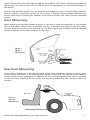 5
5
-
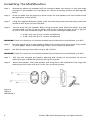 6
6
-
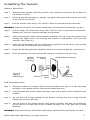 7
7
-
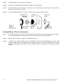 8
8
-
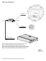 9
9
-
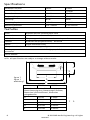 10
10
-
 11
11
-
 12
12
-
 13
13
-
 14
14
-
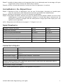 15
15
-
 16
16
-
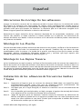 17
17
-
 18
18
-
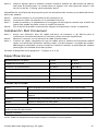 19
19
-
 20
20
-
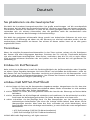 21
21
-
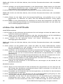 22
22
-
 23
23
-
 24
24
-
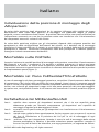 25
25
-
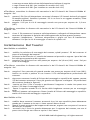 26
26
-
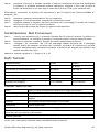 27
27
-
 28
28
-
 29
29
-
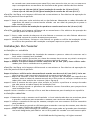 30
30
-
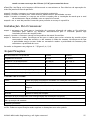 31
31
-
 32
32


Orion CO552 El manual del propietario
- Categoría
- Altavoces de coche
- Tipo
- El manual del propietario
- Este manual también es adecuado para
en otros idiomas
- français: Orion CO552 Le manuel du propriétaire
- italiano: Orion CO552 Manuale del proprietario
- English: Orion CO552 Owner's manual
- Deutsch: Orion CO552 Bedienungsanleitung
- português: Orion CO552 Manual do proprietário
Artículos relacionados
-
Sony SMU-S1 (PUM) Manual de usuario
-
Orion CO552 Ficha de datos
-
-
-
-
Orion XTR1.00TW El manual del propietario
-
-
-
-

