IQ America LM-1801-BZ Instrucciones de operación
- Categoría
- Detectores de movimiento
- Tipo
- Instrucciones de operación
Este manual también es adecuado para

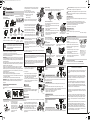
Lamp Adjustment
Twin LED Flood Light can be panned
in 40°and panned out 35°. FIG. 12
Twin LED Flood Light can be tilted
down 67°. FIG. 13
Sensor Head Adjustment
The sensor can be tilted up and
down, as well as rotated left and right.
FIG. 11
Single LED Flood Light can be tilted
down 60°. FIG. 15
Single LED Flood Light can be panned
in 60°and panned out 60°. FIG. 14
FOR MOTION SENSOR LED MODELS:
LM-2401
LM-2402
LM-2403
FOR MOTION SENSOR LED MODELS:
LM-1801
LM-1802
HI level security lighting and LO level accent lighting.
Off : HI-LO feature is off. Works with motion sensor after dark at 100% brightness.
On: At Dusk, light with turn ON at 30% and reduce to 15% in the middle of night.
At Dawn, light will turn off.
For permanent test mode (store test mode): Press and hold the button more than
5 seconds. It will toggle between test mode and normal mode.
- Lights flash 3 times - permanent test mode
- Lights flash 1 time - back to normal
67º
60º
40º
35º
60º
Press once: To learn the current level of outdoor light level and set this as your
"Dusk" level.
Press twice within 5 seconds: Back to factory default setting (+/- 5 lux)
For permanent test mode (store test mode): Press and hold the button more
than 5 seconds. It will toggle between test mode and normal mode.
- Lights flash 3 times - permanent test mode
- Lights flash 1 time - back to normal
ON-TIME:
1 min, 5 min and 10 min. Light stays ON for time set, after motion is no longer
detected.
HI level security lighting and LO level accent lighting.
Off : HI-LO feature is off. Works with motion sensor after dark at 100% brightness.
Press once: To learn the current level of outdoor light level and set this as your
Dusk level.
Press twice within 5 seconds: Back to factory default setting (+/- 5 lux)
DUSK LEARN - FIG. 16
DUSK LEARN - FIG. 17
TIME Adjustment - FIG. 17
(Dusk to Dawn Mode): At Dusk, light will turn On at 30% and reduce to
15% in the middle of the night. At Dawn, light will turn off.
(Timer mode): Seasonally Adjusted Timer: At Dusk, light turns On at 30%
and then shuts Off in the middle of the night hours (calculated automatically by
the hours of darkness).
This is a “Limited Warranty” which gives you specific legal rights. You
may also have other rights which vary from state to state and province
to province.
For a period of three years from the date of purchase, any malfunc-
tion caused by factory defective parts or workmanship will be corrected
at no charge to you. To obtain a refund or a replacement, return the
product to the place of purchase.
NOT COVERED: Repair service, adjustment and calibration due to
misuse, abuse or negligence. Unauthorized service or modification of
the product or of any furnished component will void this warranty. This
warranty does not include reimbursement for inconvenience, installation,
setup time, loss or use or unauthorized service.
This warranty covers only IQ America products and is not extended
to other equipment and components that a customer uses in conjunction
with our products.
This warranty is expressly in lieu of all other warranties, express or
implied, including any warranty, representation or condition of merchant
ability of that the products are fit for any particular purpose or use, and
specifically in lieu of all special, indirect or incidental or consequential
damages.
Repair or replacement shall be the sole remedy of the customer and
there shall be no liability on the part of IQ America for any special,
indirect, incidental or consequential damages, including but not limited
to any loss of business or profit, whether or not foreseeable. Some
states or provinces do not allow the exclusion or limitation of incidental
or consequential damages, so the above limitation or exclusion may not
apply to you. Retain receipt for warranty claims.
IQ America Three Year Warranty
Customer service number:
For problems or questions, please call us at 1-800-296-1869
Instructions: Please retain this instruction manual for future reference
USING MANUAL OVERRIDE MODE
NOTE: If the power to the
light fixture is off for more
than 5 seconds, allow the
motion sensor to warm up
prior to switching to
manual mode.
Turn the light switch Off
and back On again with
0.2 to 1.5 seconds.
Settings
On-TIME: 1 min, 5 min and 10 min. Lights stay ON for time set after motion is no
longer detected.
HI/LO Light Level Feature - FIG. 17
0116E1
EN
Instruction Manual
MOTION SENSOR LED LIGHTS
LM-1801/LM-1802
LM-2401/LM-2402/LM-2403
On
Manual mode overrides the motion sensor and
“ON-TIME” control so the light will turn ON at full
brightness.
This feature only works at night for 6 hours.
The motion sensor will reset to motion sensing
mode. Manual mode can be toggled on and off
using the light switch.
• To manually turn the lights “ON”, turn the light
switch OFF and back ON again between
0.2 to 1.5 seconds.
• To cancel the manual override mode, turn the
light switch OFF and back ON again between
0.2 to 1.5 seconds. FIG. 18
FIG. 11
FIG. 16
HI/LO Light Level Feature - FIG. 16
FIG. 17
FIG. 12 FIG. 13
FIG. 14 FIG. 15
FIG. 18
TIME Adjustment - FIG. 16
Detection Range:
Motion Sensor Light: Recommended installation height is 8 feet above the
ground. The maximum detection range is about 70 feet. FIG. 9
Note: Walking direction
when performing test.
Walk Test and Adjustment
The walk test is used to test the detection range and to
restrict it if necessary.
• Warm up time is about 60 seconds, then the unit goes
into TEST mode.
The light will turn on for about 2 seconds when
motion is detected.
• After the sensor no longer detects motion for 2 minutes,
then the unit will go into the AUTO sensing mode.
• Note the best way to perform "Walk Test"
is shown in FIG. 10
FIG. 10
180º
8 FEET
up to 70 FEET
240º
8 FEET
up to 70 FEET
FIG. 9
FIG. 8
FIG. 4
Decorative
nuts (06)
LM1801 / LM-2401 LM1802 / LM-2402
Wall mount Eave mount
or
OFF
ON
This package contains:
You will require:
Tools/Equipment need for installation
SUPERIOR ADJUSTMENT VERSATILITY
Dual Mounting Options
Rotate the body up to change from wall mount to eave mount as per drawing
below.
01 X 1
Instruction
Manual
05 X 2
Wire Nuts
06 X 2
Decorative Nuts
07 X 2
Screws
08 X 2
Screws
04 X 1
Connector
Wires
02 X 1
Mounting Bracket
with screws
03 X 1
Gasket
09 X 2
Screws
(M4 X 1.6”)
10 X 2
Screws
(M4 X 1.9”)
WARNING: This equipment has been tested and found to comply with limits
for a Class B digital device, pursuant to Part 15 of the FCC Rules. These limits
are designed to provide reasonable protection against harmful interference in a
residential installation.
This equipment generates, uses and can radiate radio frequency energy and, if
not installed and used in accordance with the instructions, may cause harmful
interference to radio communications.
However, there is no guarantee that interference will not occur in a particular
installation. If this equipment does cause harmful interference to radio or
television reception, which can be determined by turning the equipment off and
on, the user is encouraged to try to correct the interference by one or more of
the following measures:
■ Reorient or relocate the receiving antenna.
■ Increase the separation between the equipment and the receiver.
■ Connect the equipment into an outlet on a circuit different from that to which
■ the receiver is connected.
■ Consult the dealer or an experienced radio/TV technician for help.
WARNING: Changes or modifications not expressly approved by the party
responsible for compliance could void the user’s authority to operate the
equipment.
This device complies with Part 15 of the FCC Rules.
Operation is subject to the following two conditions:
(1) this device may not cause harmful interference, and
(2) this device must accept any interference received, including interference
that may cause undesired operation.
WARNING: “THIS PRODUCT MUST BE INSTALLED IN
ACCORDANCE WITH THE APPLICABLE INSTALLATION
CODE BY A PERSON FAMILIAR WITH THE CONTSTRUC-
TION AND OPERATION OF THE PRODUCT AND THE
HARZARDS INVOLVED”
Installation Procedure:
1. Switch off the power.
2. Thread the shorter set of
two screws (09) included
with the mounting bracket,
through the holes on the
back of the outer bracket.
The threads of the screws
should now be sticking out
of the front of the outer
bracket. FIG. 1
FIG. 5
FIG. 7
FIG. 2
A
H
B
5. Caulk around the edge of the lighting fixture
with silicone sealant to weatherproof around
the junction box (not included). FIG. 5
Note: Make sure all the wires are inside the junction box before attaching the
main body to the junction box.
4. Plug the wire connector (04) into the plug on
the back of the lighting fixture.
Align the body of the lighting fixture over the
mounting bracket screws and mount the
fixture so the screws come through the front
of the light fixture.
Attach the decorative nuts (06) to the screws
and tighten. FIG. 4
3. Insert the house wiring and wire nuts into the
junction box, but make sure the connector
wire (04) is still outside of the junction box.
Attach the gasket (03) to the mounting
bracket (02), so that the mounting bracket
screws go through the gasket (03). FIG. 3
Tighten the mounting bracket screws at the
center of the mounting bracket (see inset C)
Potential high temperature!
Do not touch the metal parts of the device and keep a
minimum distance of 1/2 inch around the floodlight
housing. FIG. 7
Hot Surface Do Not Touch
6. Turn on power.
Conduct walk test to adjust sensor coverage area.
Sensor will be in TEST mode automatically for 2
minutes. Lights will come on for approximately
2 to 3 seconds in TEST mode. FIG. 6
Sensor stays in TEST mode until it no longer senses
motion for more than two minutes, then it will revert
to the AUTO sensing mode.
CAUTION!
Installation Advice:
Since the motion detector reacts to variations in temperature; avoid the following
situations:
WARNING
• Do not aim motion detectors at objects with highly-
reflective surfaces, like swimming pools, mirrors, etc...
• Do not install motion detectors near heat sources
such as heating outlets, air conditioning systems,
dryer vents, lighting fixtures, etc. FIG. 8
• Do not aim the motion detector at objects that
move in the wind, such as tree limbs or bushes,
large plants, etc...
Note: If the mounting bracket screws (09) are not long enough to allow the
decorative nuts (06) to be threaded on them, then you will need to replace the
shorter set of screws (09) with the longer set of screws (10). This is usually due
to the junction box being recessed into the wall.
If the longer mounting bracket screws are necessary, remove the fixture from
the screws, unplug the connector wire, remove the mounting bracket and
replace the mounting bracket screws with the longer screws. Repeat the
installation steps starting with section 2.
Install the mounting bracket (02) with screws (07 or 08)
to the junction box. FIG. 2 Connect the house wires to
the connector wires (04).
Connect the white wire (N) to the white
connector wire and black wire (H) to black
connector wire with wire nuts (05).
Connect the ground wire from the house wiring to
the ground screw on the mounting bracket (02).
• White to white (N)
• Black to black (H)
FIG. 3
Gasket (03)
C
screw (09)
FIG. 1
FIG. 6
150105-US-LM-2401-2402-2403&LM-1801&LM-1802- IM.pdf 1 5/1/2016 9:37:40 AM

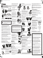
Ajuste de la lámpara
TEl reflector con bombilla LED doble
se puede inclinar hacia abajo 67°.
FIG. 13
Ajuste del cabezal del sensor
El sensor puede inclinarse hacia arriba
y abajo, así como también puede rotar
hacia la derecha y la izquierda.
El reflector con bombilla LED simple se
puede inclinar hacia abajo 60°. FIG. 15
PARA MODELOS LED CON SENSOR DE MOVIMIENTO:
LM-2401
LM-2402
LM-2403
PARA MODELOS LED CON SENSOR DE
MOVIMIENTO:
LM-1801
LM-1802
Nivel alto de iluminación de seguridad y nivel bajo de iluminación decorativa.
Apagado: La característica ALTO/BAJO está apagada. Funciona con un sensor
de movimiento luego de que oscurece con el 100% de su brillo.
Encendido: Al atardecer, la luz se encenderá al 30% y se reducirá al 15% en el
medio de la noche. Al amanecer, la luz se apagará.
Para el modo de prueba permanente (modo de prueba almacenado): mantenga
presionado el botón por más de
5 segundos. Se mantendrá entre el modo de prueba y el modo normal.
- Destella 3 veces: modo de prueba permanente.
- Destella una vez: regresará a su estado normal.
67º
60º
40º
35º
60º
Pulse una vez: para conocer el nivel actual del nivel de iluminación para
exteriores y establecer esto como su nivel para el atardecer.
Presione dos veces en menos de 5 segundos: para regresar a la configuración
predeterminada de fábrica (+/- 5 lux)
Para el modo de prueba permanente (modo de prueba almacenado):
Mantenga presionado el botón por más de 5 segundos. Se mantendrá entre el
modo de prueba y el modo normal.
- Destella 3 veces: modo de prueba permanente.
- Destella una vez: regresará a su estado normal.
A TIEMPO:
1 minuto, 5 minutos y 10 minutos. Las luces permanecen ENCENDIDAS por el
tiempo programado, luego de que no se haya detectado ningún movimiento
más.
Nivel alto de iluminación de seguridad y nivel bajo de iluminación decorativa.
Pulse una vez: para conocer el nivel actual del nivel de iluminación para exteriores
y establecer esto como su nivel para el atardecer.
Presione dos veces en menos de 5 segundos: para regresar a la configuración
predeterminada de fábrica (+/- 5 lux)
NIVEL DE LUZ AL ATARDECER - FIG. 17
Ajuste del TIEMPO - FIG. 17
(Modo De atardecer a amanecer): Al atardecer, la luz se encenderá al
30% y se reducirá al 15% en el medio de la noche. Al amanecer, la luz se
apagará.
(Modo Temporizador): Temporizador de ajuste por estación: Al atardecer,
las luces se encienden a un 30% y luego se apagan en las horas del medio de
la noche (se calcula de manera automática por la cantidad de horas de
oscuridad).
Esta es una “Garantía limitada" que le da derechos legales específi-
cos. Además, puede tener otros derechos que varían según el estado o
la provincia.
Por un período de tres años desde la fecha de compra, cualquier
falla causada por piezas con defectos de fábrica o con defectos en la
mano de obra se enmendarán sin cargo. Para obtener un reembolso o
un reemplazo, devuelva el producto al lugar de compra.
LA GARANTÍA NO CUBRE: servicio de reparación, ajuste y
calibración debido al mal uso, abuso o negligencia. La reparación no
autorizada o la modificación del producto o de cualquiera de los
componentes suministrados anularán esta garantía. Esta garantía no
incluye reembolsos por inconvenientes, instalación, tiempo de ensam-
blaje, pérdida o uso, o reparación no autorizada.
Esta garantía cubre solamente los productos IQ America y no se
extiende a otros equipos y componentes que un cliente usa en conjunto
con nuestros productos.
Esta garantía reemplaza expresamente todas las demás garantías,
explícitas o implícitas, incluida cualquier garantía, representación o
condición de comerciabilidad o idoneidad de los productos para
cualquier propósito o uso particular y específicamente excluye todos los
daños especiales, indirectos, incidentales o resultantes.
La reparación o el reemplazo serán los únicos resarcimientos para el
cliente y no habrá responsabilidad alguna de parte de IQ America por
ningún daño especial, indirecto, accidental o resultante, lo que incluye,
entre otros, la pérdida de actividad o lucro cesante, fueren o no
previsibles. Algunos estados o provincias no permiten la exclusión o
limitación de los daños accidentales o resultantes, por lo tanto puede
que la limitación o la exclusión anterior no se aplique en su caso.
Conserve el recibo para reclamos de la garantía.
Garantía IQ America de tres años
Número de servicio al cliente:
Si tiene alguna consulta o problema, llámenos al 1-800-296-1869
Instrucciones: conserve este manual de instrucciones para referencia futura.
UTILIZAR EL MODO ANULACIÓN MANUAL
NOTA: si el suministro
eléctrico de la lámpara se
desconectó por más de 5
segundos, deje que el
sensor de movimiento se
caliente antes de
cambiarlo a modo
manual.
Cambie el interruptor a
Apagado y a Encendido
de nuevo entre 0.2 y 1.5
segundos.
Graduaciones
A TIEMPO: 1 minuto, 5 minutos y 10 minutos. Las luces permanecerán ENCENDI-
DAS por el tiempo programado luego de que no se haya detectado ningún
movimiento más.
Característica de nivel de luz ALTO/BAJO - FIG. 17
ES
Manual de instrucciones
LUCES LED CON DETECTOR DE MOVIMIENTO
LM-1801/LM-1802
LM-2401/LM-2402/LM-2403
El modo manual anula el sensor de movimiento
y el control “A TIEMPO” para que la luz se
ENCIENDA con su brillo máximo.
Esta característica solo funciona por 6 horas.
TEl sensor de movimiento se reiniciará en el
modo de detección de movimiento. El modo
manual se puede alternar entre encendido y
apagado utilizando el interruptor de la luz.
3DUDSRGHU(1&(1'(5ODOX]GHPDQHUD
manual, cambie el interruptor de luz a
APAGADO y a ENCENDIDO de nuevo entre 0.2
segundos y 1.5 segundos.
3DUDFDQFHODUHOPRGRGHDQXODFLyQPDQXDO
cambie el interruptor de luz a APAGADO y a
ENCENDIDO de nuevo entre 0.2 segundos y
1.5 segundos. FIG. 18
FIG. 11
FIG. 16
FIG. 17
FIG. 12 FIG. 13
FIG. 14 FIG. 15
FIG. 18
Ajuste del TIEMPO - FIG. 16
Alcance de detección:
Luz con detector de movimiento: La altura de instalación recomendada es 2,43
metros por encima del suelo. El alcance máximo de detección es de aproxi-
madamente 21,33 metros. FIG. 9
Nota: Dirección de la
caminata cuando se
lleva a cabo la prueba.
Caminata de prueba y ajuste
La caminata de prueba se utiliza para probar el alcance
de detección y para restringirlo si es necesario.
(OWLHPSRGHFDOHQWDPLHQWRHVGHDSUR[LPDGDPHQWH
segundos, luego la unidad entra en modo TEST.
La luz se encenderá durante 2 segundos aproximada-
mente cuando se detecte movimiento.
/XHJRGHTXHHOVHQVRU\DQRGHWHFWHPRYLPLHQWRSRU
minutos, entonces la unidad entrará al modo de detección
automática.
1RWHTXHODPHMRUPDQHUDGHUHDOL]DUODFDPLQDWDGH
prueba se muestra en la FIG. 10
FIG. 10
180º
Hasta 21,33 METROS
240º
2,43 METROS
Hasta 21,33 METROS
FIG. 9
FIG. 8
2,43 METROS
El reflector con bombilla LED doble se
puede colocar dentro de los 40° y
colocar fuera de los 35°. FIG. 12
El reflector con bombilla LED simple se
puede colocar dentro de los 60° y
colocar fuera de los 60°. FIG. 14
Característica de nivel de
luz ALTO/BAJO - FIG. 16
NIVEL DE LUZ AL ATARDECER - FIG. 16
Apagado: la característica ALTO/BAJO está apagada. Funciona con un sensor
de movimiento luego de que oscurece con el 100% de su brillo.
FIG. 4
Tuercas
decorativas (06)
LM1801 / LM-2401 LM1802 / LM-2402
Montaje en alero o en pared
o
Este paquete contiene:
Requerirá:
Herramientas/equipamiento
necesario para la instalación.
VERSATILIDAD DE AJUSTE SUPERIOR
Opciones de montaje dobles
Rotar el cuerpo hacia arriba para cambiar de montaje en pared a montaje en
alero de acuerdo con la imagen que se muestra a continuación.
01 X 1
Manual de i
nstrucciones
05 X 2
Empalmes
plásticos
06 X 2
Tuercas
decorativas
07 X 2
Tornillos
08 X 2
Tornillos
04 X 1
Cables
conectores
02 X 1
Soporte de montaje
con tornillos
03 X 1
Empaquetadura
09 X 2
Tornillos
(M4 X 4,06 cm)
10 X 2
Tornillos
(M4 X 4,82 cm)
ADVERTENCIA: Este equipo ha sido probado, y se ha verificado que cumple
con los límites para un dispositivo digital clase B, conforme a la sección 15 de
las reglas de la FCC. Estos límites se han diseñado para proporcionar una
protección razonable contra las interferencias perjudiciales en una instalación
residencial.
Este equipo genera, utiliza y puede irradiar energía de radiofrecuencia y, si no
se instala y se usa de acuerdo con las instrucciones, puede causar interferen-
cia perjudicial para las comunicaciones de radio.
Sin embargo, no se garantiza que no se producirán interferencias en una
instalación en particular. Si este equipo genera una interferencia perjudicial
para la recepción de radio o televisión, lo que se puede determinar apagando
y encendiendo el equipo, se recomienda al usuario que intente corregir la
interferencia con una o más de las siguientes medidas:
Ŷ5HRULHQWDURUHXELFDUODDQWHQDGHUHFHSFLyQ
Ŷ$XPHQWDUODVHSDUDFLyQHQWUHHOHTXLSR\HOUHFHSWRU
Ŷ&RQHFWDUHOHTXLSRDXQWRPDFRUULHQWHGHXQFLUFXLWRGLVWLQWRGHOTXHXVDHO
receptor.
Ŷ6ROLFLWDUD\XGDDOGLVWULEXLGRURDXQWpFQLFRFRQH[SHULHQFLDHQUDGLR79
ADVERTENCIA: los cambios o modificaciones que no estén expresamente
aprobados por la parte responsable del cumplimiento podrían anular la
autorización del usuario para utilizar el equipo.
Este dispositivo cumple con la sección 15 de las reglas de la FCC.
El funcionamiento está sujeto a las siguientes dos condiciones:
(1) este dispositivo no debe causar interferencia perjudicial y
(2) debe aceptar cualquier interferencia recibida, incluida la interferencia que
pudiese causar un funcionamiento no deseado.
ADVERTENCIA: “
ESTE PRODUCTO SE DEBE INSTALAR DE
ACUERDO CON EL CÓDIGO DE INSTALACIÓN QUE CORRE-
SPONDA Y DEBE HACERLO UNA PERSONA FAMILIARIZADA
CON LA FABRICACIÓN Y EL FUNCIONAMIENTO DEL PRODUCTO
Y LOS PELIGROS INVOLUCRADOS”.
Procedimiento de instalación:
1. Desconecte el suministro
eléctrico.
2. Enrosque el juego más corto
de dos tornillos (09) incluido el
soporte de montaje, a través
de los orificios en la parte
posterior del soporte exterior.
FIG. 5
FIG. 7
FIG. 2
A
H
B
5. Aplique masilla de calafateo siliconada alrededor
del contorno de la lámpara para impermeabilizar
el área de la caja de unión (no se incluye). FIG. 5
Nota: asegúrese de que todos los cables se encuentren dentro de la caja de
unión antes de fijar el cuerpo principal a la caja de unión.
4. Inserte el cable conector (04) en el enchufe
de la parte posterior de la lámpara.
Alinee el cuerpo de la lámpara sobre los
tornillos del soporte de montaje e instale la
lámpara de modo que los tornillos pasen
hasta el frente de la lámpara.
Fije las tuercas decorativas (06) a los
tornillos y apriételas. FIG. 4
3. Inserte el cableado de la casa y los
empalmes plásticos en la caja de unión,
pero asegúrese de que el cable conector
(04) siga fuera de la caja de unión.
Fije la empaquetadura 03 al soporte de
montaje (02), de manera que los tornillos
para el soporte de montaje atraviesen la
empaquetadura (03). FIG. 3
Apriete los tornillos del soporte de montaje
en el centro del soporte de montaje (consulte
el recuadro C)
Potencial de alta temperatura
No toque las partes metálicas del dispositivo y
mantenga una distancia mínima de 1,27 cm alrededor
de la carcasa del reflector. FIG. 7
Superficie caliente. No tocar.
6. Encienda el suministro eléctrico.
Realice una caminata de prueba para regular el área
de cobertura del sensor.
El sensor estará en el modo TEST (PRUEBA) de
manera automática durante 2 minutos. Las luces se
encenderán por aproximadamente
2 o 3 segundos en el modo TEST. FIG. 6
El sensor permanece en el modo TEST hasta que ya
no detecte movimiento por más de dos minutos;
luego regresará al modo de detección automática.
PRECAUCIÓN
Consejo de instalación:
Debido a que el detector de movimiento reacciona a las variaciones de tempera-
tura, evite las siguientes situaciones:
ADVERTENCIA
1RDSXQWHORVVHQVRUHVGHPRYLPLHQWRKDFLDREMHWRV
de superficies altamente reflectoras, como piscinas,
espejos, etc.
1RLQVWDOHGHWHFWRUHVGHPRYLPLHQWRFHUFDGHIXHQWHV
de calor, como salidas de calefacción, sistemas de
aire acondicionado, respiraderos para secadoras,
lámparas, etc. FIG. 8
1RDSXQWHHOGHWHFWRUGHPRYLPLHQWRKDFLDREMHWRV
que se muevan con el viento, como ramas de árboles
o arbustos, plantas grandes, etc.
Nota: Si los tornillos del soporte de montaje (09) no son lo suficientemente
largos para permitir ajustarles las tuercas decorativas (06), entonces necesi-
tará reemplazar el juego de tornillos cortos (09) por el juego de tornillos largos
(10). Esto generalmente se debe a que la caja de unión está empotrada en la
pared.
Si los tornillos más largos del soporte de montaje son necesarios, retire el
ensamble de los tornillos, desenchufe el cable conector, extraiga el soporte de
montaje y reemplace los tornillos del soporte de montaje por los tornillos más
largos. Repita estos pasos de instalación desde la sección 2
Instale el soporte de montaje (02) en la caja de unión
utilizando los tornillos (07 o 08). FIG. 2. Conecte los
cables de la casa a los cables conectores (04).
Conecte el cable blanco (N) al cable conector
blanco y el cable negro (H) al cable conector
negro utilizando empalmes plásticos (05).
Conecte el cable de puesta a tierra del cableado
de la casa al tornillo de puesta a tierra en el
soporte de montaje (02).
%ODQFRFRQEODQFR1
1HJURFRQQHJUR+
FIG. 3
Empaquetadura (03)
C
Tornillos (09)
FIG. 1
FIG. 6
Las roscas de los tornillos ahora
deberían estar sobresaliendo de
la parte frontal del soporte exterior.
FIG. 1
APAGADO
ENCENDIDO
APAGADO
ENCENDIDO
150105-US-LM-2401-2402-2403&LM-1801&LM-1802- IM.pdf 2 5/1/2016 9:37:43 AM
-
 1
1
-
 2
2


IQ America LM-1801-BZ Instrucciones de operación
- Categoría
- Detectores de movimiento
- Tipo
- Instrucciones de operación
- Este manual también es adecuado para

