Makita XPK02 Manual de usuario
- Categoría
- Cepilladoras eléctricas
- Tipo
- Manual de usuario
Este manual también es adecuado para

INSTRUCTION MANUAL
MANUAL DE INSTRUCCIONES
Cordless Planer
Cepillo Inalámbrico
XPK02
IMPORTANT: Read Before Using.
IMPORTANTE: Lea antes de usar.

2 ENGLISH
ENGLISH (Original instructions)
SPECIFICATIONS
Model: XPK02
Rated voltage D.C. 18 V
Planing width 82 mm (3-1/4")
Planing depth 3 mm (1/8")
Shiplapping depth 25 mm (1")
No load speed 12,000 /min
Overall length 366 mm (14-3/8")
Net weight 3.3 - 3.6 kg (7.3 - 7.9 lbs)
•
Due to our continuing program of research and development, the specications herein are subject to change without notice.
• Specications and battery cartridge may differ from country to country.
• The weight may differ depending on the attachment(s), including the battery cartridge. The lightest and heavi-
est combinations, according to EPTA-Procedure 01/2014, are shown in the table.
Applicable battery cartridge and charger
Battery cartridge
BL1815N / BL1820B / BL1830 / BL1830B / BL1840B / BL1850B / BL1860B
Charger DC18RC / DC18RD / DC18RE / DC18SD / DC18SE / DC18SF
•
Some of the battery cartridges and chargers listed above may not be available depending on your region of residence.
WARNING: Only use the battery cartridges and chargers listed above. Use of any other battery cartridges
and chargers may cause injury and/or re.
SAFETY WARNINGS
General power tool safety warnings
WARNING: Read all safety warnings, instruc-
tions, illustrations and specications provided
with this power tool. Failure to follow all instructions
listed below may result in electric shock, re and/or
serious injury.
Save all warnings and instruc-
tions for future reference.
The term "power tool" in the warnings refers to your
mains-operated (corded) power tool or battery-operated
(cordless) power tool.
Work area safety
1. Keep work area clean and well lit. Cluttered or
dark areas invite accidents.
2. Do not operate power tools in explosive atmo-
spheres, such as in the presence of ammable
liquids, gases or dust. Power tools create sparks
which may ignite the dust or fumes.
3. Keep children and bystanders away while
operating a power tool. Distractions can cause
you to lose control.
Electrical Safety
1. Power tool plugs must match the outlet. Never
modify the plug in any way. Do not use any
adapter plugs with earthed (grounded) power
tools. Unmodied plugs and matching outlets will
reduce risk of electric shock.
2. Avoid body contact with earthed or grounded
surfaces, such as pipes, radiators, ranges and
refrigerators. There is an increased risk of elec-
tric shock if your body is earthed or grounded.
3. Do not expose power tools to rain or wet con-
ditions. Water entering a power tool will increase
the risk of electric shock.
4. Do not abuse the cord. Never use the cord for
carrying, pulling or unplugging the power tool.
Keep cord away from heat, oil, sharp edges
or moving parts. Damaged or entangled cords
increase the risk of electric shock.
5. When operating a power tool outdoors, use an
extension cord suitable for outdoor use. Use of
a cord suitable for outdoor use reduces the risk of
electric shock.
6. If operating a power tool in a damp location is
unavoidable, use a ground fault circuit inter-
rupter (GFCI) protected supply. Use of a GFCI
reduces the risk of electric shock.
7. Power tools can produce electromagnetic
elds (EMF) that are not harmful to the user.
However, users of pacemakers and other similar
medical devices should contact the maker of their
device and/or doctor for advice before operating
this power tool.

3 ENGLISH
Personal Safety
1. Stay alert, watch what you are doing and use
common sense when operating a power tool.
Do not use a power tool while you are tired or
under the inuence of drugs, alcohol or med-
ication. A moment of inattention while operating
power tools may result in serious personal injury.
2. Use personal protective equipment. Always
wear eye protection. Protective equipment such
as dust mask, non-skid safety shoes, hard hat, or
hearing protection used for appropriate conditions
will reduce personal injuries.
3. Prevent unintentional starting. Ensure the
switch is in the off-position before connecting
to power source and/or battery pack, picking
up or carrying the tool. Carrying power tools with
your nger on the switch or energising power tools
that have the switch on invites accidents.
4. Remove any adjusting key or wrench before
turning the power tool on. A wrench or a key left
attached to a rotating part of the power tool may
result in personal injury.
5. Do not overreach. Keep proper footing and
balance at all times. This enables better control
of the power tool in unexpected situations.
6. Dress properly. Do not wear loose clothing or
jewellery. Keep your hair, clothing and gloves
away from moving parts. Loose clothes, jewel-
lery or long hair can be caught in moving parts.
7. If devices are provided for the connection of
dust extraction and collection facilities, ensure
these are connected and properly used. Use of
dust collection can reduce dust-related hazards.
8.
Do not let familiarity gained from frequent use
of tools allow you to become complacent and
ignore tool safety principles. A careless action can
cause severe injury within a fraction of a second.
9. Always wear protective goggles to protect
your eyes from injury when using power tools.
The goggles must comply with ANSI Z87.1 in
the USA.
It is an employer's responsibility to enforce the
use of appropriate safety protective equipment
by the tool operators and by other persons in
the immediate working area.
Power tool use and care
1. Do not force the power tool. Use the correct
power tool for your application. The correct
power tool will do the job better and safer at the
rate for which it was designed.
2. Do not use the power tool if the switch does
not turn it on and off. Any power tool that cannot
be controlled with the switch is dangerous and
must be repaired.
3. Disconnect the plug from the power source
and/or remove the battery pack, if detachable,
from the power tool before making any adjust-
ments, changing accessories, or storing power
tools. Such preventive safety measures reduce
the risk of starting the power tool accidentally.
4. Store idle power tools out of the reach of chil-
dren and do not allow persons unfamiliar with
the power tool or these instructions to operate
the power tool. Power tools are dangerous in the
hands of untrained users.
5.
Maintain power tools and accessories. Check for
misalignment or binding of moving parts, break-
age of parts and any other condition that may
affect the power tool’s operation. If damaged, have
the power tool repaired before use. Many accidents
are caused by poorly maintained power tools.
6. Keep cutting tools sharp and clean. Properly
maintained cutting tools with sharp cutting edges
are less likely to bind and are easier to control.
7. Use the power tool, accessories and tool bits
etc. in accordance with these instructions, tak-
ing into account the working conditions and
the work to be performed. Use of the power tool
for operations different from those intended could
result in a hazardous situation.
8.
Keep handles and grasping surfaces dry, clean
and free from oil and grease. Slippery handles
and grasping surfaces do not allow for safe handling
and control of the tool in unexpected situations.
9. When using the tool, do not wear cloth work
gloves which may be entangled. The entangle-
ment of cloth work gloves in the moving parts may
result in personal injury.
Battery tool use and care
1. Recharge only with the charger specied by
the manufacturer. A charger that is suitable for
one type of battery pack may create a risk of re
when used with another battery pack.
2. Use power tools only with specically desig-
nated battery packs. Use of any other battery
packs may create a risk of injury and re.
3. When battery pack is not in use, keep it away
from other metal objects, like paper clips,
coins, keys, nails, screws or other small metal
objects, that can make a connection from one
terminal to another. Shorting the battery termi-
nals together may cause burns or a re.
4. Under abusive conditions, liquid may be
ejected from the battery; avoid contact. If con-
tact accidentally occurs, ush with water. If
liquid contacts eyes, additionally seek medical
help. Liquid ejected from the battery may cause
irritation or burns.
5. Do not use a battery pack or tool that is dam-
aged or modied. Damaged or modied batteries
may exhibit unpredictable behaviour resulting in
re, explosion or risk of injury.
6. Do not expose a battery pack or tool to re or
excessive temperature. Exposure to re or tem-
perature above 130 °C may cause explosion.
7. Follow all charging instructions and do not
charge the battery pack or tool outside the
temperature range specied in the instruc-
tions. Charging improperly or at temperatures
outside the specied range may damage the
battery and increase the risk of re.
Service
1. Have your power tool serviced by a qualied
repair person using only identical replacement
parts. This will ensure that the safety of the power
tool is maintained.
2. Never service damaged battery packs. Service
of battery packs should only be performed by the
manufacturer or authorized service providers.

4 ENGLISH
3. Follow instruction for lubricating and chang-
ing accessories.
4. Do not modify or attempt to repair the appli-
ance or the battery pack except as indicated in
the instructions for use and care.
Cordless Planer Safety Warnings
1. Wait for the cutter to stop before setting the
tool down. An exposed rotating cutter may
engage the surface leading to possible loss of
control and serious injury.
2. Use clamps or another practical way to secure
and support the workpiece to a stable plat-
form. Holding the workpiece by your hand or
against the body leaves it unstable and may lead
to loss of control.
3. Rags, cloth, cord, string and the like should
never be left around the work area.
4. Avoid cutting nails. Inspect for and remove all
nails from the workpiece before operation.
5. Use only sharp blades. Handle the blades very
carefully.
6. Be sure the blade installation bolts are
securely tightened before operation.
7. Hold the tool rmly with both hands.
8. Keep hands away from rotating parts.
9. Before using the tool on an actual workpiece,
let it run for a while. Watch for vibration or
wobbling that could indicate poor installation
or a poorly balanced blade.
10. Make sure the blade is not contacting the
workpiece before the switch is turned on.
11. Wait until the blade attains full speed before
cutting.
12. Always switch off and wait for the blades to
come to a complete stop before adjusting
depth of cut.
13. Never stick your nger into the chip chute.
Chute may jam when cutting damp wood.
Clean out chips with a stick.
14. Do not leave the tool running. Operate the tool
only when hand-held.
15.
When replace the blades or some parts on the
drum, make sure to replace the parts on both
sides of the drum as a set. Otherwise, the resulting
imbalance will cause vibration and shorten tool life.
16. Use only Makita blades specied in this
manual.
17. Always use the correct dust mask/respirator
for the material and application you are work-
ing with.
18. Operate the tool on stable condition. Operation
on unstable condition may cause a damage injury.
SAVE THESE INSTRUCTIONS.
WARNING: DO NOT let comfort or familiarity
with product (gained from repeated use) replace
strict adherence to safety rules for the subject
product.
MISUSE or failure to follow the safety rules stated
in this instruction manual may cause serious
personal injury.
Important safety instructions for
battery cartridge
1.
Before using battery cartridge, read all instruc-
tions and cautionary markings on (1) battery char-
ger, (2) battery, and (3) product using battery.
2. Do not disassemble battery cartridge.
3. If operating time has become excessively
shorter, stop operating immediately. It may
result in a risk of overheating, possible burns
and even an explosion.
4.
If electrolyte gets into your eyes, rinse them out
with clear water and seek medical attention right
away. It may result in loss of your eyesight.
5. Do not short the battery cartridge:
(1) Do not touch the terminals with any con-
ductive material.
(2) Avoid storing battery cartridge in a con-
tainer with other metal objects such as
nails, coins, etc.
(3) Do not expose battery cartridge to water
or rain.
A battery short can cause a large current
ow, overheating, possible burns and even a
breakdown.
6. Do not store the tool and battery cartridge in
locations where the temperature may reach or
exceed 50 °C (122 °F).
7. Do not incinerate the battery cartridge even if
it is severely damaged or is completely worn
out. The battery cartridge can explode in a re.
8. Be careful not to drop or strike battery.
9. Do not use a damaged battery.
10.
The contained lithium-ion batteries are subject to
the Dangerous Goods Legislation requirements.
For commercial transports e.g. by third parties,
forwarding agents, special requirement on pack-
aging and labeling must be observed.
For preparation of the item being shipped, consult-
ing an expert for hazardous material is required.
Please also observe possibly more detailed
national regulations.
Tape or mask off open contacts and pack up the
battery in such a manner that it cannot move
around in the packaging.
11. When disposing the battery cartridge, remove
it from the tool and dispose of it in a safe
place. Follow your local regulations relating to
disposal of battery.
12. Use the batteries only with the products
specied by Makita. Installing the batteries to
non-compliant products may result in a re, exces-
sive heat, explosion, or leak of electrolyte.
13. If the tool is not used for a long period of time,
the battery must be removed from the tool.
SAVE THESE INSTRUCTIONS.
CAUTION: Only use genuine Makita batteries.
Use of non-genuine Makita batteries, or batteries that
have been altered, may result in the battery bursting
causing res, personal injury and damage. It will
also void the Makita warranty for the Makita tool and
charger.

5 ENGLISH
Tips for maintaining maximum
battery life
1. Charge the battery cartridge before completely
discharged. Always stop tool operation and
charge the battery cartridge when you notice
less tool power.
2. Never recharge a fully charged battery car-
tridge. Overcharging shortens the battery
service life.
3. Charge the battery cartridge with room tem-
perature at 10 °C - 40 °C (50 °F - 104 °F). Let
a hot battery cartridge cool down before
charging it.
4. Charge the battery cartridge if you do not use
it for a long period (more than six months).
Symbols
The followings show the symbols used for tool.
volts
direct current
no load speed
revolutions or reciprocation per minute
Important safety instructions for
wireless unit
1. Do not disassemble or tamper with the wire-
less unit.
2. Keep the wireless unit away from young chil-
dren. If accidentally swallowed, seek medical
attention immediately.
3. Use the wireless unit only with Makita tools.
4. Do not expose the wireless unit to rain or wet
conditions.
5. Do not use the wireless unit in places where
the temperature exceeds 50°C (122°F).
6. Do not operate the wireless unit in places
where medical instruments, such as heart
pace makers are nearby.
7. Do not operate the wireless unit in places
where automated devices are nearby. If oper-
ated, automated devices may develop malfunction
or error.
8. Do not operate the wireless unit in places
under high temperature or places where
static electricity or electrical noise could be
generated.
9. The wireless unit can produce electromagnetic
elds (EMF) but they are not harmful to the
user.
10. The wireless unit is an accurate instrument. Be
careful not to drop or strike the wireless unit.
11. Avoid touching the terminal of the wireless
unit with bare hands or metallic materials.
12. Always remove the battery on the product
when installing the wireless unit into it.
13. When opening the lid of the slot, avoid the
place where dust and water may come into the
slot. Always keep the inlet of the slot clean.
14. Always insert the wireless unit in the correct
direction.
15. Do not press the wireless activation button
on the wireless unit too hard and/or press the
button with an object with a sharp edge.
16. Always close the lid of the slot when
operating.
17. Do not remove the wireless unit from the slot
while the power is being supplied to the tool.
Doing so may cause a malfunction of the wireless
unit.
18. Do not remove the sticker on the wireless unit.
19. Do not put any sticker on the wireless unit.
20. Do not leave the wireless unit in a place where
static electricity or electrical noise could be
generated.
21. Do not leave the wireless unit in a place sub-
ject to high heat, such as a car sitting in the
sun.
22. Do not leave the wireless unit in a dusty or
powdery place or in a place corrosive gas
could be generated.
23. Sudden change of the temperature may bedew
the wireless unit. Do not use the wireless unit
until the dew is completely dried.
24. When cleaning the wireless unit, gently wipe
with a dry soft cloth. Do not use benzine, thin-
ner, conductive grease or the like.
25. When storing the wireless unit, keep it in the
supplied case or a static-free container.
26. Do not insert any devices other than Makita
wireless unit into the slot on the tool.
27. Do not use the tool with the lid of the slot dam-
aged. Water, dust, and dirt come into the slot may
cause malfunction.
28. Do not pull and/or twist the lid of the slot more
than necessary. Restore the lid if it comes off
from the tool.
29. Replace the lid of the slot if it is lost or
damaged.
SAVE THESE INSTRUCTIONS.

6 ENGLISH
FUNCTIONAL DESCRIPTION
CAUTION: Always be sure that the tool is
switched off and the battery cartridge is removed
before adjusting or checking function on the tool.
Installing or removing battery cartridge
CAUTION: Always switch off the tool before
installing or removing of the battery cartridge.
CAUTION:
Hold the tool and the battery cartridge
rmly when installing or removing battery cartridge.
Failure to hold the tool and the battery cartridge rmly may
cause them to slip off your hands and result in damage to
the tool and battery cartridge and a personal injury.
2
1
3
► 1. Red indicator 2. Button 3. Battery cartridge
To remove the battery cartridge, slide it from the tool
while sliding the button on the front of the cartridge.
To install the battery cartridge, align the tongue on the
battery cartridge with the groove in the housing and slip
it into place. Insert it all the way until it locks in place
with a little click. If you can see the red indicator on the
upper side of the button, it is not locked completely.
CAUTION: Always install the battery cartridge
fully until the red indicator cannot be seen. If not,
it may accidentally fall out of the tool, causing injury to
you or someone around you.
CAUTION: Do not install the battery cartridge
forcibly. If the cartridge does not slide in easily, it is
not being inserted correctly.
Tool / battery protection system
The tool is equipped with a tool/battery protection sys-
tem. This system automatically cuts off power to the
motor to extend tool and battery life. The tool will auto-
matically stop during operation if the tool or battery is
placed under one of the following conditions.
Overload protection
When the tool is operated in a manner that causes it to
draw an abnormally high current, the tool automatically
stops. In this situation, turn the tool off and stop the
application that caused the tool to become overloaded.
Then turn the tool on to restart.
Overheat protection
When the tool is overheated, the tool stops automati-
cally, and the battery indicator blink about 60 seconds.
In this situation, let the tool cool down before turning the
tool on again.
On Blinking
Overdischarge protection
When the battery capacity becomes low, the tool stops
automatically. If the product does not operate even
when the switches are operated, remove the batteries
from the tool and charge the batteries.
Indicating the remaining battery
capacity
When you pull the switch trigger, the battery indicator
shows the remaining battery capacity.
1
► 1. Battery indicator
The remaining battery capacity is shown as the follow-
ing table.
Battery indicator status Remaining
battery
capacity
On
Off
Blinking
50% to 100%
20% to 50%
0% to 20%
Charge the
battery

7 ENGLISH
Indicating the remaining battery
capacity
Only for battery cartridges with the indicator
1
2
► 1. Indicator lamps 2. Check button
Press the check button on the battery cartridge to indi-
cate the remaining battery capacity. The indicator lamps
light up for a few seconds.
Indicator lamps Remaining
capacity
Lighted Off Blinking
75% to 100%
50% to 75%
25% to 50%
0% to 25%
Charge the
battery.
The battery
may have
malfunctioned.
NOTE: Depending on the conditions of use and the
ambient temperature, the indication may differ slightly
from the actual capacity.
Adjusting depth of cut
CAUTION: Be sure the blades stopped com-
pletely before adjusting depth of cut.
Depth of cut may be adjusted by simply turning the
knob on the front of the tool so that the pointer points
the desired depth of cut.
2
1
► 1. Pointer 2. Knob
Switch action
WARNING: Before installing the battery car-
tridge into the tool, always check to see that the
switch trigger actuates properly and returns to
the "OFF" position when released.
WARNING: NEVER defeat the lock-off button
by taping down or some other means. A switch with
a negated lock-off button may result in unintentional
operation and serious personal injury.
WARNING: NEVER use the tool if it runs when
you simply pull the switch trigger without press-
ing the lock-off button. A switch in need of repair
may result in unintentional operation and serious
personal injury. Return tool to a Makita service center
for proper repairs BEFORE further usage.
To prevent the switch trigger from being accidentally
pulled, a lock-off button is provided. To start the tool,
depress the lock-off button and pull the switch trigger.
Release the switch trigger to stop.
2
1
► 1. Switch trigger 2. Lock-off button
NOTICE: Do not pull the switch trigger hard
without pressing in the lock-off button. This can
cause switch breakage.
Electric brake
This tool is equipped with an electric brake. If the tool
consistently fails to quickly stop after the switch trigger
is released, have the tool serviced at a Makita service
center.

8 ENGLISH
Automatic speed change function
This tool has "high speed mode" and "high torque mode".
The tool automatically changes the operation mode
depending on the work load. When the work load is low,
the tool will run in the "high speed mode" for quicker cut-
ting operation. When the work load is high, the tool will run
in the "high torque mode" for powerful cutting operation.
1
► 1. Mode indicator
The mode indicator lights up in green when the tool is
running in "high torque mode".
If the tool is operated with excessive load, the mode indica-
tor will blink in green. The mode indicator stops blinking and
then lights up or turns off if you reduce the load on the tool.
Mode indicator status Operation
mode
On Off Blinking
High speed
mode
High torque
mode
Overload
alert
Foot
After a cutting operation, raise the backside of the tool
and a foot comes under the level of the rear base. This
prevents the planer blades to be damaged.
1 2 3
► 1. Planer blade 2. Rear base 3. Foot
ASSEMBLY
CAUTION: Always be sure that the tool is
switched off and the battery cartridge is removed
before carrying out any work on the tool.
Box wrench storage
When not in use, store the box wrench as shown in the
gure to keep it from being lost.
1
► 1. Box wrench
Removing or installing planer
blades
CAUTION: Tighten the blade installation bolts
carefully when attaching the blades to the tool.
Always check to see they are tightened securely.
A loose installation bolt can be dangerous.
CAUTION: Handle the blades very carefully.
Use gloves or rags to protect your ngers or
hands when removing or installing the blades.
CAUTION: Use only the Makita wrench pro-
vided to remove or install the blades. Failure to do
so may result in overtightening or insufcient tighten-
ing of the installation bolts. This could cause an injury.
NOTICE: To install planer blades, clean out all
chips or foreign matter adhering to the drum or
the planer blades. Use planer blades of the same
dimensions and weight, otherwise drum oscilla-
tion/vibration, causing poor planing action, and
tool breakdown will result.

9 ENGLISH
For tool with conventional planer
blades
1. To remove the conventional planer blades from
the tool, unscrew the installation bolts with the box
wrench.
The drum plate and the conventional planer blade
with adjusting plate come off.
2
1
3
4
► 1. Box wrench 2. Installation bolt 3. Drum plate
4. Conventional blade (with adjusting plate)
2. Unscrew and remove the adjusting plate.
1
2
3
► 1. Screw 2. Adjusting plate 3. Conventional planer
blade
3. To install the conventional planer blades, place
the conventional planer blade on the blade gauge
so that the blade edge is perfectly ush with the
inside edge of the blade gauge.
4. Place the adjusting plate on the conventional
planer blade, then simply press in the heel of the
adjusting plate ush with the backside of the blade
gauge.
5. Tighten two screws on the adjusting plate while
the adjusting plate being pressed.
5
3
1
6
5
31
24
6
2
4
7
7
► 1. Blade gauge 2. Inside edge of blade gauge
3. Conventional planer blade 4. Blade edge (of con-
ventional planer blade) 5. Adjusting plate 6. Screw
7. Heel
6. Clean out all chips or foreign matter adhering to
the drum and the conventional planer blade.
7. Slip the heel of the adjusting plate into the drum
groove, then t the drum plate on it.
1 2
3 4
► 1. Drum groove 2. Heel 3. Drum plate 4. Installation
bolt
8. Tighten all the installation bolts evenly and alter-
nately with the box wrench.
9. Repeat the above procedures for the other con-
ventional planer blade.

10 ENGLISH
For tool with mini planer blades
1. To remove the mini planer blades from the tool,
loosen the installation bolts one turn with the box
wrench.
2
1
► 1. Box wrench 2. Installation bolt
2. Slide and remove the mini planer blade from the
belt side of the tool.
Using the haft of the box wrench makes it easier
and safety.
1
2
► 1. Haft of the box wrench 2. Mini planer blade
3. To install the mini planer blades, clean out all
chips or foreign matter adhering to the drum and
the mini planer blade.
4. Slide the mini planer blade from opposite side of
the belt of the tool.
5. Tighten all the installation bolts evenly and alter-
nately with the box wrench.
6. Repeat the above procedures for the other mini
planer blade.
To calibrate the relation between the set plate and the
adjusting plate, perform the following procedure.
1. Loosen the installation bolts one turn with the box
wrench, remove the mini planer blades from the
tool rst, and then remove the installation bolts.
The drum plate and the set plate with adjusting
plate come off.
2. Loosen the screws one turn on the adjusting plate.
1
2
3
► 1. Screw 2. Adjusting plate 3. Set plate
3. Clean out all chips or foreign matter adhering
to the set plate with adjusting plate and the mini
planer blade.
4. Place the mini planer blade on the blade gauge
so that the blade edge is perfectly ush with the
inside edge of the blade gauge.
5. Place the set plate with the adjusting plate, so that
the locating lugs of the set plate align on the rest
of the mini planer blade.
6. Press in the heel of the adjusting plate ush with
the backside of the blade gauge.
7. Tighten two screws on the adjusting plate while
the adjusting plate being pressed.
6
3
1
7
6
51
24
2
4
5
8
8
3
► 1. Blade gauge 2. Inside edge of blade gauge
3. Mini planer blade 4. Blade edge (of mini planer
blade) 5. Set plate 6. Adjusting plate 7. Screw
8. Heel

11 ENGLISH
8. Slip the heel of the adjusting plate into the groove
of the drum.
1 2 3 4
► 1. Drum groove 2. Heel 3. Drum plate 4. Installation
bolt
9.
Screw all the installation bolts with the box wrench.
Then install the mini planer blade.
For the correct planer blade setting
Your planing surface will end up rough and uneven, unless the blade is set properly and securely.
The blade must be mounted so that the cutting edge is absolutely level, that is, parallel to the surface of the rear
base.
Refer to some examples below for proper and improper settings.
Planing surface Blade setting Cause
Correct setting
(A)
(B)
Although this side view
cannot show it, the
edge of the blades run
perfectly parallel to rear
base surface
Gouging at start
(A)
(B)
Both blade edges fails
to protrude enough in
relation to rear base
line.
Gouging at end
(B)
(A)
One or both blade
edges protrude too far
in relation to rear base
line.
Aslope in surface
(B)
(B)
(A)
One or both blades fails
to have edge parallel to
rear base line.
(A): Front base (Movable shoe)
(B): Rear base (Stationary shoe)

12 ENGLISH
Change of chip discharge direction
Chip discharge direction can be changed to the right or
left. To change the direction, pull out the stopper while
turning it slightly backward and t in it in one of two
openings on the opposite side of chip discharge so that
the recessed part ts to protrusion.
1
► 1. Stopper
2
1
► 1. Recessed part 2. Protrusion
Dust bag
Optional accessory
Attach the dust bag onto the chip discharge opening. The
chip discharge opening is tapered. When attaching the dust
bag, push it onto the chip discharge opening rmly as far as
it will go to prevent it from coming off during operation.
1
2
► 1. Dust bag 2. Chip discharge opening
When the dust bag is about half full, remove the dust
bag from the tool and pull the fastener out. Empty the
dust bag. Tap the dust bag lightly to remove particles
adhering inside, which might hamper further collection.
1
► 1. Fastener
NOTE: If you connect a Makita vacuum cleaner to
this tool, more efcient and cleaner operations can be
performed.
Connecting a vacuum cleaner
When you wish to perform clean planing operation,
connect a Makita vacuum cleaner to your tool. Connect
a hose of the vacuum cleaner to the chip discharge
opening as shown in the gures.
1
► 1. Vacuum cleaner

13 ENGLISH
Elbow
Optional accessory
Use of elbow allows change of chip discharge direction
to perform cleaner work.
Insert the elbow into the chip discharge opening. To
remove it, just pull it out.
1
► 1. Elbow
OPERATION
Hold the tool rmly with one hand on the knob and the
other hand on the switch handle when operating the
tool.
Planing operation
First, rest the tool front base at upon the workpiece
surface without the blades making any contact. Switch
on and wait until the blades attain full speed. Then
move the tool gently forward. Apply pressure on the
front of tool at the start of planing, and at the back at the
end of planing. Planing will be easier if you incline the
workpiece in stationary fashion, so that you can plane
somewhat downhill.
The speed and depth of cut determine the kind of nish.
The tool keeps cutting at a speed that will not result in
jamming by chips. For rough cutting, the depth of cut
can be increased, while for a good nish you should
reduce the depth of cut and advance the tool more
slowly.
1
2
► 1. Start 2. End
Shiplapping (Rabbeting)
To make a stepped cut as shown in the gure, use the
edge fence (guide rule).
Install the edge fence on the tool. Secure it with the
washer and thumb screw (A). Loosen the thumb screw
(B) and adjust the edge fence until it comes in contact
with the side of the workpiece. Then tighten the thumb
screw (B) securely.
1
2
3
► 1. Screw (A) 2. Screw (B) 3. Edge fence
Draw a cutting line on the workpiece. Align the blade
edge with the cutting line.
Adjust the shiplapping depth using a depth guide.
When planing, move the tool with the edge fence ush
with the side of the workpiece. Otherwise, uneven
planing may result.
3 2
1
► 1. Blade edge 2. Cutting line 3. Depth guide

14 ENGLISH
NOTICE: The blade edge should be made to
protrude outside slightly (0.2 - 0.4 mm(1/64")) for
shiplapping.
You can extend the length of the fence by attaching an
extra piece of wood. Convenient holes are provided in
the fence for this purpose.
Chamfering
To make a chamfering cut as shown in the gure, align
one of three "V" grooves in the front base with the edge
of the workpiece and plane it.
1
2
3
► 1. V groove (medium amount of chamfering) 2. V
groove (small amount of chamfering) 3. V groove
(great amount of chamfering)
Use of chamfering rule (optional accessory) assures
more tool stability when chamfering.
To install the chamfering rule, remove two screws on
both sides of the front of the tool.
Then install the chamfering rule on the front base of the
tool and secure it the screws as shown in the gure.
1
2
► 1. Chamfering rule 2. Screw
When doing a great amount of chamfering, place an
edge of chamfering rule so that it contacts workpiece
and make many passes of planing as shown in the
gure.
1
ab
► 1. Edge of chamfering rule

15 ENGLISH
WIRELESS ACTIVATION
FUNCTION
What you can do with the wireless
activation function
The wireless activation function enables clean and com-
fortable operation. By connecting a supported vacuum
cleaner to the tool, you can run the vacuum cleaner
automatically along with the switch operation of the tool.
To use the wireless activation function, prepare follow-
ing items:
• A wireless unit (optional accessory)
• A vacuum cleaner which supports the wireless
activation function
The overview of the wireless activation function
setting is as follows. Refer to each section for detail
procedures.
1. Installing the wireless unit
2. Tool registration for the vacuum cleaner
3. Starting the wireless activation function
Installing the wireless unit
Optional accessory
CAUTION: Place the tool on a at and stable
surface when installing the wireless unit.
NOTICE: Clean the dust and dirt on the tool
before installing the wireless unit. Dust or dirt
may cause malfunction if it comes into the slot of the
wireless unit.
NOTICE: To prevent the malfunction caused by
static, touch a static discharging material, such
as a metal part of the tool, before picking up the
wireless unit.
NOTICE: When installing the wireless unit,
always be sure that the wireless unit is inserted
in the correct direction and the lid is completely
closed.
1. Open the lid on the tool as shown in the gure.
1
► 1. Lid
2.
Insert the wireless unit to the slot and then close the lid.
When inserting the wireless unit, align the projections
with the recessed portions on the slot.
1
2
4
3
►
1. Wireless unit 2. Projection 3. Lid 4. Recessed portion
When removing the wireless unit, open the lid slowly.
The hooks on the back of the lid will lift the wireless unit
as you pull up the lid.
1
2
3
► 1. Wireless unit 2. Hook 3. Lid
After removing the wireless unit, keep it in the supplied
case or a static-free container.

16 ENGLISH
NOTICE: Always use the hooks on the back of
the lid when removing the wireless unit. If the
hooks do not catch the wireless unit, close the lid
completely and open it slowly again.
Tool registration for the vacuum
cleaner
NOTE: A Makita vacuum cleaner supporting the
wireless activation function is required for the tool
registration.
NOTE: Finish installing the wireless unit to the tool
before starting the tool registration.
NOTE: During the tool registration, do not pull the
switch trigger or turn on the power switch on the
vacuum cleaner.
NOTE: Refer to the instruction manual of the vacuum
cleaner, too.
If you wish to activate the vacuum cleaner along with
the switch operation of the tool, nish the tool registra-
tion beforehand.
1. Install the batteries to the vacuum cleaner and the
tool.
2. Set the stand-by switch on the vacuum cleaner to
"AUTO".
1
► 1. Stand-by switch
3. Press the wireless activation button on the vac-
uum cleaner for 3 seconds until the wireless activation
lamp blinks in green. And then press the wireless acti-
vation button on the tool in the same way.
2
1
1
2
► 1. Wireless activation button 2. Wireless activation
lamp
If the vacuum cleaner and the tool are linked success-
fully, the wireless activation lamps will light up in green
for 2 seconds and start blinking in blue.
NOTE: The wireless activation lamps nish blinking
in green after 20 seconds elapsed. Press the wireless
activation button on the tool while the wireless acti-
vation lamp on the cleaner is blinking. If the wireless
activation lamp does not blink in green, push the wire-
less activation button briey and hold it down again.
NOTE: When performing two or more tool registra-
tions for one vacuum cleaner, nish the tool registra-
tion one by one.
Starting the wireless activation
function
NOTE: Finish the tool registration for the vacuum
cleaner prior to the wireless activation.
NOTE: Refer to the instruction manual of the vacuum
cleaner, too.
After registering a tool to the vacuum cleaner, the
vacuum cleaner will automatically runs along with the
switch operation of the tool.
1. Install the wireless unit to the tool.

17 ENGLISH
2.
Connect the hose of the vacuum cleaner with the tool.
3. Set the stand-by switch on the vacuum cleaner to
"AUTO".
1
► 1. Stand-by switch
4. Push the wireless activation button on the tool
briey. The wireless activation lamp will blink in blue.
1
2
► 1. Wireless activation button 2. Wireless activation
lamp
5. Pull the switch trigger of the tool. Check if the
vacuum cleaner runs while the switch trigger is being
pulled.
To stop the wireless activation of the vacuum cleaner,
push the wireless activation button on the tool.
NOTE: The wireless activation lamp on the tool will
stop blinking in blue when there is no operation for
2 hours. In this case, set the stand-by switch on the
vacuum cleaner to "AUTO" and push the wireless
activation button on the tool again.
NOTE: The vacuum cleaner starts/stops with a delay.
There is a time lag when the vacuum cleaner detects
a switch operation of the tool.
NOTE: The transmission distance of the wireless unit
may vary depending on the location and surrounding
circumstances.
NOTE: When two or more tools are registered to one
vacuum cleaner, the vacuum cleaner may start run-
ning even if you don't pull the switch trigger because
another user is using the wireless activation function.

18 ENGLISH
Description of the wireless activation lamp status
1
► 1. Wireless activation lamp
The wireless activation lamp shows the status of the wireless activation function. Refer to the table below for the
meaning of the lamp status.
Status Wireless activation lamp Description
Color
On
Blinking
Duration
Standby Blue
2 hours The wireless activation of the vacuum cleaner is available. The
lamp will automatically turn off when no operation is performed
for 2 hours.
When
the tool is
running.
The wireless activation of the vacuum cleaner is available and the
tool is running.
Tool
registration
Green
20 seconds Ready for the tool registration. Waiting for the registration by the
vacuum cleaner.
2 seconds The tool registration has been nished. The wireless activation
lamp will start blinking in blue.
Cancelling
tool
registration
Red
20 seconds Ready for the cancellation of the tool registration. Waiting for the
cancellation by the vacuum cleaner.
2 seconds The cancellation of the tool registration has been nished. The
wireless activation lamp will start blinking in blue.
Others Red
3 seconds The power is supplied to the wireless unit and the wireless activa-
tion function is starting up.
Off - - The wireless activation of the vacuum cleaner is stopped.

19 ENGLISH
Cancelling tool registration for the
vacuum cleaner
Perform the following procedure when cancelling the
tool registration for the vacuum cleaner.
1.
Install the batteries to the vacuum cleaner and the tool.
2. Set the stand-by switch on the vacuum cleaner to
"AUTO".
1
► 1. Stand-by switch
3. Press the wireless activation button on the vac-
uum cleaner for 6 seconds. The wireless activation
lamp blinks in green and then become red. After that,
press the wireless activation button on the tool in the
same way.
2
1
1
2
► 1. Wireless activation button 2. Wireless activation
lamp
If the cancellation is performed successfully, the wire-
less activation lamps will light up in red for 2 seconds
and start blinking in blue.
NOTE: The wireless activation lamps nish blinking in
red after 20 seconds elapsed. Press the wireless acti-
vation button on the tool while the wireless activation
lamp on the cleaner is blinking. If the wireless acti-
vation lamp does not blink in red, push the wireless
activation button briey and hold it down again.

20 ENGLISH
Troubleshooting for wireless activation function
Before asking for repairs, conduct your own inspection rst. If you nd a problem that is not explained in the manual,
do not attempt to dismantle the tool. Instead, ask Makita Authorized Service Centers, always using Makita replace-
ment parts for repairs.
State of abnormality Probable cause (malfunction) Remedy
The wireless activation lamp does
not light/blink.
The wireless unit is not installed into the tool.
The wireless unit is improperly installed
into the tool.
Install the wireless unit correctly.
The terminal of the wireless unit and/or
the slot is dirty.
Gently wipe off dust and dirt on the terminal of the
wireless unit and clean the slot.
The wireless activation button on the
tool has not been pushed.
Push the wireless activation button on the tool
briey.
The stand-by switch on the vacuum
cleaner is not set to "AUTO".
Set the stand-by switch on the vacuum cleaner to
"AUTO".
No power supply
Supply the power to the tool and the vacuum cleaner.
Cannot nish tool registration / can-
celling tool registration successfully.
The wireless unit is not installed into the tool.
The wireless unit is improperly installed
into the tool.
Install the wireless unit correctly.
The terminal of the wireless unit and/or
the slot is dirty.
Gently wipe off dust and dirt on the terminal of the
wireless unit and clean the slot.
The stand-by switch on the vacuum
cleaner is not set to "AUTO".
Set the stand-by switch on the vacuum cleaner to
"AUTO".
No power supply
Supply the power to the tool and the vacuum cleaner.
Incorrect operation
Push the wireless activation button briey and perform
the tool registration/cancellation procedures again.
The tool and vacuum cleaner are away
from each other (out of the transmission
range).
Get the tool and vacuum cleaner closer to each
other. The maximum transmission distance is
approximately 10 m however it may vary according
to the circumstances.
Before nishing the tool registration/
cancellation;
- the switch trigger on the tool is pulled or;
- the power button on the vacuum
cleaner is turned on.
Push the wireless activation button briey and
perform the tool registration/cancellation procedures
again.
The tool registration procedures for the
tool or vacuum cleaner have not nished.
Perform the tool registration procedures for both the
tool and the vacuum cleaner at the same timing.
Radio disturbance by other appliances
which generate high-intensity radio
waves.
Keep the tool and vacuum cleaner away from the
appliances such as Wi-Fi devices and microwave
ovens.
The vacuum cleaner does not run
along with the switch operation of
the tool.
The wireless unit is not installed into the tool.
The wireless unit is improperly installed
into the tool.
Install the wireless unit correctly.
The terminal of the wireless unit and/or
the slot is dirty.
Gently wipe off dust and dirt on the terminal of the
wireless unit and clean the slot.
The wireless activation button on the
tool has not been pushed.
Push the wireless activation button briey and make
sure that the wireless activation lamp is blinking
in blue.
The stand-by switch on the vacuum
cleaner is not set to "AUTO".
Set the stand-by switch on the vacuum cleaner to
"AUTO".
More than 10 tools are registered to the
vacuum cleaner.
Perform the tool registration again.
If more than 10 tools are registered to the vacuum cleaner,
the tool registered earliest will be cancelled automatically.
The vacuum cleaner erased all tool registrations.
Perform the tool registration again.
No power supply
Supply the power to the tool and the vacuum cleaner.
The tool and vacuum cleaner are away
from each other (out of the transmission
range).
Get the tool and vacuum cleaner closer each other. The
maximum transmission distance is approximately 10 m
however it may vary according to the circumstances.
Radio disturbance by other appliances
which generate high-intensity radio waves.
Keep the tool and vacuum cleaner away from the appli-
ances such as Wi-Fi devices and microwave ovens.
The vacuum cleaner runs while the
tool's switch trigger is not pulled.
Other users are using the wireless
activation of the vacuum cleaner with
their tools.
Turn off the wireless activation button of the other
tools or cancel the tool registration of the other
tools.

21 ENGLISH
MAINTENANCE
CAUTION: Always be sure that the tool is
switched off and the battery cartridge is removed
before attempting to perform inspection or
maintenance.
NOTICE: Never use gasoline, benzine, thinner,
alcohol or the like. Discoloration, deformation or
cracks may result.
To maintain product SAFETY and RELIABILITY,
repairs, any other maintenance or adjustment should
be performed by Makita Authorized or Factory Service
Centers, always using Makita replacement parts.
Chip discharge opening cleaning
Clean the chip discharge opening regularly.
Use a compressed air to clean the clogged chip dis-
charge opening.
Sharpening the blades
For conventional planer blades only
Always keep your blades sharp for the best perfor-
mance possible. Use the sharpening holder to remove
nicks and produce a ne edge.
1
► 1. Sharpening holder
First, loosen the two wing nuts on the holder and insert
the blades (A) and (B), so that they contact the sides
(C) and (D). Then tighten the wing nuts.
5
4
2
3
1
► 1. Wing nut 2. Blade (A) 3. Blade (B) 4. Side (D)
5. Side (C)
Immerse the dressing stone in water for 2 or 3 minutes
before sharpening. Hold the holder so that the both
blades contact the dressing stone for simultaneous
sharpening at the same angle.
OPTIONAL ACCESSORIES
CAUTION: These accessories or attachments
are recommended for use with your Makita tool
specied in this manual. The use of any other
accessories or attachments might present a risk of
injury to persons. Only use accessory or attachment
for its stated purpose.
If you need any assistance for more details regarding
these accessories, ask your local Makita Service Center.
• High-speed steel Planer blade
•
Tungsten-carbide Planer blade (For longer blade life)
• Mini planer blade
• Sharpening holder assembly
• Blade gauge
• Set plate set
• Edge fence (Guide rule)
• Dressing stone
• Dust bag assembly
• Elbow
• Chamfering rule assembly
• Wireless unit
• Makita genuine battery and charger
NOTE: Some items in the list may be included in the
tool package as standard accessories. They may
differ from country to country.
MAKITA LIMITED WARRANTY
Please refer to the annexed warranty sheet for the
most current warranty terms applicable to this product.
If annexed warranty sheet is not available, refer to the
warranty details set forth at below website for your
respective country.
United States of America: www.makitatools.com
Canada: www.makita.ca
Other countries: www.makita.com

22 ESPAÑOL
ESPAÑOL (Instrucciones originales)
ESPECIFICACIONES
Modelo: XPK02
Tensión nominal 18 V c.c.
Ancho de cepillado 82 mm (3-1/4″)
Profundidad de cepillado 3 mm (1/8″)
Profundidad de rebajado 25 mm (1″)
Velocidad sin carga 12 000 r/min
Longitud total 366 mm (14-3/8″)
Peso neto 3,3 kg - 3,6 kg (7,3 lbs - 7,9 lbs)
• Debido a nuestro continuo programa de investigación y desarrollo, las especicaciones aquí incluidas están
sujetas a cambio sin previo aviso.
• Las especicaciones y el cartucho de batería pueden variar de país a país.
• El peso puede variar en función de los accesorios, incluido el cartucho de batería. En la tabla se muestra la
combinación de peso más ligero y más pesado conforme al procedimiento 01/2014 de EPTA.
Cartucho de batería y cargador aplicables
Cartucho de batería
BL1815N / BL1820B / BL1830 / BL1830B / BL1840B / BL1850B / BL1860B
Cargador DC18RC / DC18RD / DC18RE / DC18SD / DC18SE / DC18SF
• Algunos de los cartuchos de batería y cargadores enumerados arriba podrían no estar disponibles depen-
diendo de su área de residencia.
ADVERTENCIA: Use únicamente los cartuchos de batería y los cargadores indicados arriba. El uso de
cualquier otro cartucho de batería y cargador podría ocasionar una lesión y/o un incendio.
ADVERTENCIAS DE
SEGURIDAD
Advertencias generales de seguridad
para herramientas eléctricas
ADVERTENCIA: Lea todas las advertencias
de seguridad, instrucciones, ilustraciones y espe-
cicaciones suministradas con esta herramienta
eléctrica. El no seguir todas las instrucciones indi-
cadas a continuación podría ocasionar una descarga
eléctrica, incendio y/o lesiones graves.
Conserve todas las advertencias
e instrucciones como referencia
en el futuro.
En las advertencias, el término “herramienta eléctrica”
se reere a su herramienta eléctrica de funcionamiento
con conexión a la red eléctrica (con cableado eléctrico)
o herramienta eléctrica de funcionamiento a batería
(inalámbrica).
Seguridad en el área de trabajo
1. Mantenga el área de trabajo limpia y bien ilu-
minada. Las áreas oscuras o desordenadas son
propensas a accidentes.
2. No utilice las herramientas eléctricas en
atmósferas explosivas, tal como en la presen-
cia de líquidos, gases o polvo inamables. Las
herramientas eléctricas crean chispas que pueden
prender fuego al polvo o los humos.
3. Mantenga a los niños y curiosos alejados
mientras utiliza una herramienta eléctrica. Las
distracciones le pueden hacer perder el control.
Seguridad eléctrica
1. Las clavijas de conexión de las herramientas
eléctricas deberán encajar perfectamente en la
toma de corriente. No modique nunca la cla-
vija de conexión de ninguna forma. No utilice
ninguna clavija adaptadora con herramientas
eléctricas que tengan conexión a tierra (puesta
a tierra). La utilización de clavijas no modica-
das y que encajen perfectamente en la toma de
corriente reducirá el riesgo de que se produzca
una descarga eléctrica.
2. Evite tocar con el cuerpo supercies conec-
tadas a tierra o puestas a tierra tales como
tubos, radiadores, cocinas y refrigeradores. Si
su cuerpo es puesto a tierra o conectado a tierra
existirá un mayor riesgo de que sufra una des-
carga eléctrica.
3. No exponga las herramientas eléctricas a la
lluvia ni a condiciones húmedas. La entrada de
agua en una herramienta eléctrica aumentará el
riesgo de que se produzca una descarga eléctrica.

23 ESPAÑOL
4. No maltrate el cable. Nunca utilice el cable
para transportar, jalar o desconectar la herra-
mienta eléctrica. Mantenga el cable alejado del
calor, aceite, objetos cortantes o piezas móvi-
les. Los cables dañados o enredados aumentan
el riesgo de sufrir una descarga eléctrica.
5. Cuando utilice una herramienta eléctrica en
exteriores, utilice un cable de extensión apro-
piado para uso en exteriores. La utilización de
un cable apropiado para uso en exteriores redu-
cirá el riesgo de que se produzca una descarga
eléctrica.
6. Si no es posible evitar usar una herramienta
eléctrica en condiciones húmedas, utilice un
alimentador protegido con interruptor de cir-
cuito de falla a tierra (ICFT). El uso de un ICFT
reduce el riesgo de descarga eléctrica.
7. Las herramientas eléctricas pueden producir
campos electromagnéticos (CEM) que no son
dañinos para el usuario. Sin embargo, si los
usuarios tienen marcapasos y otros dispositivos
médicos similares, deberán consultar al fabricante
de su dispositivo y/o a su médico antes de operar
esta herramienta eléctrica.
Seguridad personal
1. Manténgase alerta, preste atención a lo que
está haciendo y utilice su sentido común
cuando opere una herramienta eléctrica. No
utilice una herramienta eléctrica cuando esté
cansado o bajo la inuencia de drogas, alco-
hol o medicamentos. Un momento de distracción
mientras opera las herramientas eléctricas puede
terminar en una lesión grave.
2. Use equipo de protección personal. Póngase
siempre protección para los ojos. El equipo
protector tal como máscara contra el polvo, zapa-
tos de seguridad antiderrapantes, casco rígido y
protección para oídos utilizado en las condiciones
apropiadas reducirá el riesgo de lesiones.
3. Impida el encendido accidental. Asegúrese
de que el interruptor esté en la posición de
apagado antes de conectar a la alimentación
eléctrica y/o de colocar el cartucho de batería,
así como al levantar o cargar la herramienta.
Cargar las herramientas eléctricas con su dedo
en el interruptor o enchufarlas con el interrup-
tor encendido hace que los accidentes sean
comunes.
4. Retire cualquier llave de ajuste o llave de
apriete antes de encender la herramienta. Una
llave de ajuste o llave de apriete que haya sido
dejada puesta en una parte giratoria de la herra-
mienta eléctrica puede ocasionar alguna lesión.
5. No utilice la herramienta donde no alcance.
Mantenga los pies sobre suelo rme y el equi-
librio en todo momento. Esto permite un mejor
control de la herramienta eléctrica en situaciones
inesperadas.
6. Use una vestimenta apropiada. No use ropa
suelta ni alhajas. Mantenga el cabello, la ropa
y los guantes alejados de las piezas móviles.
Las prendas de vestir holgadas, las alhajas y
el cabello largo suelto podrían engancharse en
estas piezas móviles.
7.
Si dispone de dispositivos para la conexión de
equipos de extracción y recolección de polvo,
asegúrese de conectarlos y utilizarlos debida-
mente. Hacer uso de la recolección de polvo puede
reducir los riesgos relacionados con el polvo.
8. No permita que la familiaridad adquirida
debido al uso frecuente de las herramientas
haga que se sienta conado e ignore los prin-
cipios de seguridad de las herramientas. Un
descuido podría ocasionar una lesión grave en
una fracción de segundo.
9. Utilice siempre gafas protectoras para prote-
ger sus ojos de lesiones al usar herramientas
eléctricas. Las gafas deben cumplir con la
Norma ANSI Z87.1 en EUA.
Es responsabilidad del empleador imponer
el uso de equipos protectores de seguridad
apropiados a los operadores de la herramienta
y demás personas cerca del área de trabajo.
Mantenimiento y uso de la herramienta eléctrica
1. No fuerce la herramienta eléctrica. Utilice la
herramienta eléctrica correcta para su aplica-
ción. La herramienta eléctrica adecuada hará un
mejor trabajo y de forma más segura a la veloci-
dad para la que ha sido fabricada.
2.
No utilice la herramienta eléctrica si el inte-
rruptor no la enciende y apaga. Cualquier herra-
mienta eléctrica que no pueda ser controlada con
el interruptor es peligrosa y debe ser reemplazada.
3. Desconecte la clavija de la fuente de alimen-
tación y/o retire la batería de la herramienta
eléctrica, en caso de ser removible, antes de
realizar ajustes, cambiar accesorios o almace-
nar las herramientas eléctricas. Tales medidas
de seguridad preventivas reducirán el riesgo
de poner en marcha la herramienta eléctrica de
forma accidental.
4. Guarde la herramienta eléctrica que no use
fuera del alcance de los niños y no permita
que las personas que no están familiarizadas
con ella o con las instrucciones la operen. Las
herramientas eléctricas son peligrosas en manos
de personas que no saben operarlas.
5. Dé mantenimiento a las herramientas eléctri-
cas y los accesorios. Compruebe que no haya
piezas móviles desalineadas o estancadas,
piezas rotas y cualquier otra condición que
pueda afectar al funcionamiento de la herra-
mienta eléctrica. Si la herramienta eléctrica
está dañada, haga que la reparen antes de
utilizarla. Muchos de los accidentes son ocasio-
nados por no dar un mantenimiento adecuado a
las herramientas eléctricas.
6. Mantenga las herramientas de corte limpias
y losas. Si recibe un mantenimiento adecuado
y tiene los bordes alados, es probable que la
herramienta se atasque menos y sea más fácil
controlarla.
7. Utilice la herramienta eléctrica, los accesorios
y las brocas de acuerdo con estas instruccio-
nes, considerando las condiciones laborales
y el trabajo a realizar. Si utiliza la herramienta
eléctrica para realizar operaciones distintas de
las indicadas, podrá presentarse una situación
peligrosa.

24 ESPAÑOL
8. Mantenga los mangos y supercies de asi-
miento secos, limpios y libres de aceite o
grasa. Los mangos y supercies de asimiento
resbalosos no permiten una manipulación segura
ni el control de la herramienta en situaciones
inesperadas.
9. Cuando vaya a utilizar esta herramienta, evite
usar guantes de trabajo de tela ya que éstos
podrían atorarse. Si los guantes de trabajo de
tela llegaran a atorarse en las piezas móviles,
esto podría ocasionar lesiones personales.
Uso y cuidado de la herramienta a batería
1. Recargue sólo con el cargador especicado
por el fabricante. Un cargador que es adecuado
para un solo tipo de batería puede generar riesgo
de incendio al ser utilizado con otra batería.
2. Utilice las herramientas eléctricas solamente
con las baterías designadas especícamente
para ellas. La utilización de cualquier otra batería
puede crear un riesgo de lesiones o incendio.
3. Cuando no se esté usando la batería, mantén-
gala alejada de otros objetos metálicos, como
sujetapapeles (clips), monedas, llaves, clavos,
tornillos u otros objetos pequeños de metal
los cuales pueden actuar creando una cone-
xión entre las terminales de la batería. Originar
un cortocircuito en las terminales puede causar
quemaduras o incendios.
4. En condiciones abusivas, podrá escapar
líquido de la batería; evite tocarlo. Si lo toca
accidentalmente, enjuague con agua. Si hay
contacto del líquido con los ojos, busque asis-
tencia médica. Puede que el líquido expulsado
de la batería cause irritación o quemaduras.
5. No utilice una herramienta ni una batería que
estén dañadas o hayan sido modicadas. Las
baterías dañadas o modicadas podrían oca-
sionar una situación inesperada provocando un
incendio, explosión o riesgo de lesiones.
6. No exponga la herramienta ni la batería al
fuego ni a una temperatura excesiva. La expo-
sición al fuego o a una temperatura superior a los
130 °C podría causar una explosión.
7. Siga todas las instrucciones para la carga y
evite cargar la herramienta o la batería fuera
del rango de temperatura especicado en
las instrucciones. Una carga inadecuada o a
una temperatura fuera del rango especicado
podría dañar la batería e incrementar el riesgo de
incendio.
Servicio
1. Haga que una persona calicada repare la
herramienta eléctrica utilizando sólo piezas de
repuesto idénticas. Esto asegura que se man-
tenga la seguridad de la herramienta eléctrica.
2. Nunca dé servicio a baterías que estén daña-
das. El servicio a las baterías solamente deberá
ser efectuado por el fabricante o un agente de
servicio autorizado.
3. Siga las instrucciones para la lubricación y
cambio de accesorios.
4. No modique ni intente reparar el aparato ni el
paquete de baterías salvo como se indique en
las instrucciones para el uso y cuidado.
Advertencias de seguridad para el
cepillo inalámbrico
1. Espere a que la pieza cortadora se detenga
antes de colocar la herramienta en el suelo. Si
la pieza cortadora queda expuesta mientras está
girando, ésta podría engancharse con la super-
cie y ocasionar una posible pérdida de control así
como lesiones graves.
2. Utilice abrazaderas o algún otro modo práctico
para asegurar y sujetar la pieza de trabajo a
una plataforma estable. Sostener la pieza de
trabajo con la mano o contra su cuerpo produce
inestabilidad y podría ocasionar una posible pér-
dida de control.
3. Nunca se deben dejar trapos, paños, cuerdas
o cordeles en el área de trabajo.
4. Evite cortar clavos. Inspeccione y quite todos
los clavos de la pieza de trabajo antes de la
operación.
5. Utilice sólo cuchillas aladas. Manipule las
cuchillas con mucho cuidado.
6. Asegúrese de que los pernos de instalación de
la cuchilla estén rmemente apretados antes
de la operación.
7.
Sujete la herramienta rmemente con ambas manos.
8.
Mantenga las manos alejadas de las piezas giratorias.
9. Antes de utilizar la herramienta en una pieza
de trabajo denitiva, déjela funcionar durante
un rato. Observe si hay vibración o bamboleo
que pueda indicar una instalación incorrecta o
una cuchilla mal equilibrada.
10. Asegúrese de que la cuchilla no esté haciendo
contacto con la pieza de trabajo antes de acti-
var el interruptor.
11. Espere hasta que la cuchilla alcance plena
velocidad antes de cortar.
12. Siempre apague la herramienta y espere a que
las cuchillas se detengan por completo antes
de ajustar la profundidad de corte.
13. Nunca coloque su dedo en el canal de absor-
ción de astillas. El canal puede obstruirse al
cortar madera húmeda. Limpie las astillas con
un palillo.
14.
No deje la herramienta en marcha. Opere la herra-
mienta solamente cuando la tenga en la mano.
15. Cuando reemplace las cuchillas o algunas
piezas del tambor, asegúrese de reemplazar
las piezas en ambos lados del tambor como un
conjunto. De lo contrario, el desequilibrio resul-
tante ocasionará vibraciones que acortarán la vida
útil de la herramienta.
16. Utilice sólo las cuchillas Makita especicadas
en este manual.
17. Siempre utilice la máscara contra polvo/respi-
rador para el material y la aplicación con los
que esté trabajando.
18. Opere la herramienta bajo condiciones esta-
bles. La operación en condiciones inestables
podría provocar un daño por lesión.
GUARDE ESTAS
INSTRUCCIONES.

25 ESPAÑOL
ADVERTENCIA: NO DEJE que la comodidad
o familiaridad con el producto (a base de utilizarlo
repetidamente) evite que siga estrictamente las
normas de seguridad para dicho producto.
El USO INCORRECTO o el no seguir las normas
de seguridad indicadas en este manual de ins-
trucciones puede ocasionar lesiones graves.
Instrucciones importantes de
seguridad para el cartucho de
batería
1. Antes de utilizar el cartucho de batería, lea
todas las instrucciones e indicaciones de
precaución en el (1) el cargador de batería, (2)
la batería, y (3) el producto con el que se utiliza
la batería.
2. No desarme el cartucho de batería.
3. Si el tiempo de operación se ha acortado en
exceso, deje de operar de inmediato. Podría
correrse el riesgo de sobrecalentamiento,
posibles quemaduras e incluso explosión.
4. En caso de que ingresen electrolitos en sus
ojos, enjuáguelos bien con agua limpia y con-
sulte de inmediato a un médico. Esto podría
ocasionar pérdida de visión.
5. Evite cortocircuitar el cartucho de batería:
(1) No toque las terminales con ningún mate-
rial conductor.
(2) Evite guardar el cartucho de batería en un
cajón junto con otros objetos metálicos,
tales como clavos, monedas, etc.
(3) No exponga el cartucho de batería al
agua o la lluvia.
Un cortocircuito en la batería puede causar
un ujo grande de corriente, sobrecalenta-
miento, posibles quemaduras e incluso una
descompostura.
6. No guarde la herramienta ni el cartucho de
batería en lugares donde la temperatura pueda
alcanzar o exceder los 50°C (122°F).
7. Nunca incinere el cartucho de batería incluso
en el caso de que esté dañado seriamente o
ya no sirva en absoluto. El cartucho de batería
puede explotar si se tira al fuego.
8. Tenga cuidado de no dejar caer ni golpear la
batería.
9. No use una batería dañada.
10. Las baterías de ión de litio están sujetas a los
requisitos reglamentarios en materia de bie-
nes peligrosos.
Para el trasporte comercial, por ej., mediante
terceros o agentes de transporte, se deben tomar
en cuenta los requisitos especiales relativos al
empaque y el etiquetado.
Para efectuar los preparativos del artículo que se
va a enviar, se requiere consultar a un experto
en materiales peligrosos. Si es posible, consulte
además otras regulaciones nacionales más deta-
lladas.
Pegue o cubra con cinta adhesiva los contactos
abiertos y empaque la batería de manera que ésta
no pueda moverse dentro del paquete.
11. Para deshacerse del cartucho de batería,
sáquelo de la herramienta y deséchelo en un
lugar seguro. Siga las regulaciones locales
relacionadas al desecho de las baterías.
12. Utilice las baterías únicamente con los pro-
ductos especicados por Makita. Instalar las
baterías en productos que no cumplan con los
requisitos podría ocasionar un incendio, un calen-
tamiento excesivo, una explosión o una fuga de
electrolito.
13. Si no se utiliza la herramienta por un
período largo, debe extraerse la batería de la
herramienta.
GUARDE ESTAS
INSTRUCCIONES.
PRECAUCIÓN: Utilice únicamente baterías
originales de Makita. El uso de baterías no origina-
les de Makita, o de baterías alteradas, puede ocasio-
nar que las baterías exploten causando un incendio,
lesiones personales y daños. Asimismo, esto inva-
lidará la garantía de Makita para la herramienta y el
cargador Makita.
Consejos para alargar al máximo
la vida útil de la batería
1. Cargue el cartucho de batería antes de que
se descargue completamente. Pare siem-
pre la operación y cargue el cartucho de
batería cuando note menos potencia en la
herramienta.
2. No cargue nunca un cartucho de batería que
esté completamente cargado. La sobrecarga
acortará la vida de servicio de la batería.
3. Cargue el cartucho de batería a una tempera-
tura ambiente de 10 °C - 40 °C (50 °F - 104 °F).
Si un cartucho de batería está caliente, déjelo
enfriar antes de cargarlo.
4. Cargue el cartucho de batería si no va a utili-
zarlo durante un período prolongado (más de
seis meses).
Símbolos
A continuación se muestran los símbolos utilizados
para la herramienta.
volts o voltios
corriente directa o continua
velocidad en vacío o sin carga
revoluciones o alternaciones por minuto,
frecuencia de rotación

26 ESPAÑOL
Instrucciones importantes de
seguridad para la unidad inalámbrica
1.
No desarme ni modique la unidad inalámbrica.
2.
Mantenga la unidad inalámbrica alejada de los
niños pequeños. En caso de ingerirla accidental-
mente, solicite atención médica de inmediato.
3. Utilice la unidad inalámbrica solamente con
herramientas de Makita.
4. No exponga la unidad inalámbrica a la lluvia ni
a condiciones de humedad.
5. No utilice la unidad inalámbrica en lugares
donde la temperatura exceda los 50°C (122°F).
6. No utilice la unidad inalámbrica en lugares
donde haya instrumentos médicos tales como
marcapasos cerca.
7. No utilice la unidad inalámbrica en lugares
donde haya dispositivos automáticos cerca.
Si se utiliza, los dispositivos automáticos podrían
causar alguna avería o error.
8. No opere la unidad inalámbrica en lugares con
alta temperatura o donde pueda generarse
electricidad estática o ruido eléctrico.
9. La unidad inalámbrica puede producir campos
electromagnéticos (CEM), sin embargo éstos
no son dañinos para el usuario.
10. La unidad inalámbrica es un instrumento de
precisión. Tenga cuidado de no dejar caer ni
golpear la unidad inalámbrica.
11.
Evite tocar la terminal de la unidad inalámbrica con
las manos descubiertas o con materiales metálicos.
12. Retire siempre la batería del producto al insta-
lar en él la unidad inalámbrica.
13.
Cuando abra la tapa de la ranura, evite el lugar donde
el polvo y el agua puedan introducirse en la ranura.
Mantenga siempre la entrada de la ranura limpia.
14. Inserte siempre la unidad inalámbrica en la
dirección correcta.
15.
No oprima el botón de activación inalámbrica en
la unidad inalámbrica demasiado fuerte, ni lo haga
con ningún objeto que tenga un borde loso.
16. Cierre siempre la tapa de la ranura durante la
operación.
17. No retire la unidad inalámbrica de la ranura
mientras se esté suministrando energía a la
herramienta. El hacerlo podría causar una avería
de la unidad inalámbrica.
18. No retire la etiqueta en la unidad inalámbrica.
19. No coloque ninguna etiqueta en la unidad
inalámbrica.
20. No deje la unidad inalámbrica en un lugar
donde pueda generarse electricidad estática o
ruido eléctrico.
21. No deje la unidad inalámbrica en un lugar
sujeto a temperaturas altas, tal como un vehí-
culo estacionado bajo el sol.
22. No deje la unidad inalámbrica en un lugar
donde haya polvo o suciedad ni en un lugar
donde pueda generarse gas corrosivo.
23. Los cambios repentinos de temperatura
podrían humedecer la unidad inalámbrica. No
utilice la unidad inalámbrica hasta que la con-
densación se haya secado por completo.
24. Cuando vaya a limpiar la unidad inalámbrica,
hágalo cuidadosamente usando un paño
suave seco. No utilice bencina, disolvente,
grasa conductora o sustancias similares.
25. Cuando vaya a almacenar la unidad inalám-
brica, guárdela en el estuche suministrado o
en un contenedor libre de electricidad estática.
26. No inserte ningún otro dispositivo que no sea
la unidad inalámbrica de Makita en la ranura de
la herramienta.
27. No utilice la herramienta si la tapa de la ranura
está dañada. La entrada de agua, polvo o sucie-
dad en la ranura podría causar una avería.
28. No jale ni tuerza la tapa de la ranura más de
lo necesario. Vuelva a colocar la tapa si ésta se
sale de la herramienta.
29. Reemplace la tapa de la ranura si llega a per-
derse o dañarse.
GUARDE ESTAS
INSTRUCCIONES.
DESCRIPCIÓN DEL
FUNCIONAMIENTO
PRECAUCIÓN: Asegúrese siempre de que la
herramienta esté apagada y el cartucho de batería
haya sido extraído antes de realizar cualquier
ajuste o comprobación en la herramienta.
Instalación o extracción del
cartucho de batería
PRECAUCIÓN: Apague siempre la herra-
mienta antes de colocar o quitar el cartucho de
batería.
PRECAUCIÓN: Sujete la herramienta y el car-
tucho de la batería con rmeza al colocar o quitar
el cartucho de batería. Si no se sujeta con rmeza la
herramienta y el cartucho de batería, puede ocasio-
nar que se resbalen de sus manos causando daños
a la herramienta y al cartucho de batería, así como
lesiones a la persona.
2
1
3
► 1. Indicador rojo 2. Botón 3. Cartucho de batería

27 ESPAÑOL
Para quitar el cartucho de batería, deslícelo de la herra-
mienta mientras desliza el botón sobre la parte delan-
tera del cartucho.
Para colocar el cartucho de batería, alinee la lengüeta
sobre el cartucho de batería con la ranura en la carcasa
y deslice en su lugar. Inserte por completo hasta que
se je en su lugar con un pequeño clic. Si puede ver el
indicador rojo del lado superior del botón, esto indica
que no ha quedado jo por completo.
PRECAUCIÓN: Introduzca siempre com-
pletamente el cartucho de batería hasta que
el indicador rojo no pueda verse. Si no, podría
accidentalmente salirse de la herramienta y caer al
suelo causando una lesión a usted o alguien a su
alrededor.
PRECAUCIÓN: No instale el cartucho de
batería a la fuerza. Si el cartucho no se desliza al
interior fácilmente, se debe a que no está siendo
insertado correctamente.
Sistema de protección para la
herramienta/batería
La herramienta está equipada con un sistema de pro-
tección para la herramienta/batería. Este sistema corta
en forma automática el suministro de energía al motor
para prolongar la vida útil de la herramienta y la batería.
La herramienta se detendrá automáticamente durante
la operación si la herramienta o la batería se someten a
una de las siguientes condiciones. En algunas condicio-
nes, los indicadores pueden encenderse.
Protección contra sobrecarga
Cuando la herramienta sea utilizada de una manera
que cause que consuma una cantidad anormalmente
alta de corriente, la herramienta se detendrá auto-
máticamente. En este caso, apague la herramienta y
detenga la aplicación que causó que la herramienta
se sobrecargara. Luego encienda la herramienta para
volver a arrancarla.
Protección contra
sobrecalentamiento
Cuando la herramienta se sobrecaliente, ésta se
detendrá automáticamente y el indicador de batería
parpadeará alrededor de 60 segundos. En este caso,
permita que la herramienta se enfríe antes de volver a
encenderla.
Encendido Parpadeando
Protección contra sobredescarga
Cuando la capacidad de la batería se reduce, la herra-
mienta se detiene automáticamente. Si el producto
no funciona incluso cuando los interruptores están
siendo operados, retire las baterías de la herramienta
y cárguelas.
Indicación de capacidad restante de la batería
Si jala el gatillo interruptor, el indicador de batería mos-
trará la capacidad restante de la batería.
1
► 1. Indicador de batería
La capacidad restante de la batería se muestra tal
como se indica en la tabla a continuación.
Estado del indicador de batería Capacidad
restante de la
batería
Encendido
Apagado
Parpadeando
50% a 100%
20% a 50%
0% a 20%
Cargar la
batería
Indicación de la capacidad restante
de la batería
Únicamente para cartuchos de batería con el indicador
1
2
► 1. Luces indicadoras 2. Botón de vericación
Oprima el botón de vericación en el cartucho de la batería
para que indique la capacidad restante de la batería. Las
luces indicadoras se iluminarán por algunos segundos.

28 ESPAÑOL
Luces indicadoras Capacidad
restante
Iluminadas Apagadas Parpadeando
75% a 100%
50% a 75%
25% a 50%
0% a 25%
Cargar la
batería.
La batería
pudo haber
funcionado
mal.
NOTA: Dependiendo de las condiciones de uso y
la temperatura ambiente, la indicación podrá diferir
ligeramente de la capacidad real.
Ajuste de la profundidad de corte
PRECAUCIÓN: Asegúrese de que las cuchi-
llas estén detenidas por completo antes de ajus-
tar la profundidad de corte.
La profundidad del corte puede ajustarse al simple-
mente girar la perilla al frente de la herramienta de tal
forma que el puntero indique la profundidad de corte
deseada.
2
1
► 1. Puntero 2. Perilla
Accionamiento del interruptor
ADVERTENCIA: Antes de insertar el car-
tucho de batería en la herramienta, compruebe
siempre y cerciórese de que el gatillo interruptor
se acciona debidamente y que vuelve a la posi-
ción “OFF” (apagado) cuando lo suelta.
ADVERTENCIA: NUNCA inhabilite el botón
de desbloqueo manteniéndolo presionado con
cinta adhesiva o mediante otro método. El uso
de un interruptor con un botón de desbloqueo inha-
bilitado puede ocasionar una operación accidental y
lesiones personales graves.
ADVERTENCIA: NUNCA use la herramienta
si se activa simplemente al jalar el gatillo inte-
rruptor sin que haya presionado el botón de
desbloqueo. El uso de un interruptor que requiere
reparación puede ocasionar una operación accidental
y lesiones personales graves. Lleve la herramienta
a un centro de servicio Makita para las reparaciones
apropiadas ANTES de continuar su uso.
El botón de desbloqueo es suministrado para evitar
jalar accidentalmente el gatillo interruptor. Para arran-
car la herramienta, presione el botón de desbloqueo y
jale el gatillo interruptor. Para detenerla, suelte el gatillo
interruptor.
2
1
► 1. Gatillo interruptor 2. Botón de desbloqueo
AVISO: No jale fuertemente el gatillo interruptor
sin presionar el botón de desbloqueo. Esto podría
dañar el interruptor.
Freno eléctrico
La herramienta está equipada con un freno eléctrico. Si
la herramienta falla constantemente en detenerse tras
soltar el gatillo interruptor, lleve la herramienta a mante-
nimiento a un centro de servicio Makita.

29 ESPAÑOL
Función de cambio de velocidad
automática
Esta herramienta cuenta con “modo de alta velocidad” y
“modo de alta torsión”.
La herramienta cambia automáticamente el modo de
operación en función de la carga de trabajo. Cuando la
carga de trabajo sea baja, la herramienta funcionará en
“modo de alta velocidad” para una operación de corte
más rápida. Cuando la carga de trabajo sea alta, la
herramienta funcionará en “modo de alta torsión” para
una operación de corte con mayor potencia.
1
► 1. Indicador de modo
El indicador de modo se encenderá en verde cuando
la herramienta esté funcionando en “modo de alta
torsión”.
Si la herramienta es operada con una carga excesiva,
el indicador de modo comenzará a parpadear en verde.
El indicador de modo dejará de parpadear y luego
se encenderá o se apagará al reducir la carga en la
herramienta.
Estado del indicador de modo Modo de
operación
Encendido Apagado
Parpadeando
Modo de alta
velocidad
Modo de alta
torsión
Alerta de
sobrecarga
Pie
Después de la operación de corte, eleve el lado poste-
rior de la herramienta de manera que el pie por debajo
del nivel de la base trasera. Esto evita que las cuchillas
del cepillo se dañen.
1 2 3
► 1. Cuchilla del cepillo 2. Base posterior 3. Pie
ENSAMBLE
PRECAUCIÓN: Asegúrese siempre de que la
herramienta esté apagada y el cartucho de batería
haya sido extraído antes de realizar cualquier
trabajo en la misma.
Almacenamiento de la llave de
bujías
Cuando no la utilice, guarde la llave de bujías tal como
se muestra en la ilustración para evitar que se pierda.
1
► 1. Llave de bujías

30 ESPAÑOL
Extracción o instalación de las
cuchillas del cepillo
PRECAUCIÓN:
Apriete con cuidado los pernos de
instalación de las cuchillas cuando coloque las cuchillas
en la herramienta. Siempre verique que estén rmemente
apretados. Un perno de instalación ojo puede ser peligroso.
PRECAUCIÓN:
Manipule las cuchillas con mucho
cuidado. Utilice guantes o trapos para proteger sus
dedos y manos cuando extraiga o instale las cuchillas.
PRECAUCIÓN:
Utilice sólo la llave Makita provista
para extraer o instalar las cuchillas. El no hacerlo podría
hacer que los pernos de instalación quedaran demasiado apre-
tados o no lo suciente. Esto podría además causar lesiones.
AVISO:
Para instalar las cuchillas del cepillo, limpie
todas las astillas y materias extrañas adheridas al tambor
o a las cuchillas del cepillo. Utilice cuchillas del cepillo de
las mismas dimensiones y peso; de lo contrario, la osci-
lación/vibración del tambor causará una acción deciente
de cepillado y se producirá una avería de la herramienta.
Para herramientas con cuchillas de
cepillo convencionales
1. Para extraer las cuchillas del cepillo convenciona-
les de la herramienta, desatornille los pernos de
instalación con la llave de bujías.
La placa del tambor y la cuchilla del cepillo con-
vencional con placa de ajuste se sueltan.
2
1
3
4
►
1. Llave de bujías 2. Perno de instalación 3. Placa del
tambor 4. Cuchilla convencional (con placa de ajuste)
2. Desatornille y retire la placa de ajuste.
1
2
3
►
1. Tornillo 2. Placa de ajuste 3. Cuchilla del cepillo convencional
3. Para instalar las cuchillas del cepillo convenciona-
les, coloque la cuchilla del cepillo convencional en
el calibrador de cuchillas, de modo que el borde
de la cuchilla quede perfectamente al ras con el
borde interior del calibrador de cuchillas.
4. Coloque la placa de ajuste en la cuchilla del
cepillo convencional, luego presione el talón de
la placa de ajuste al ras con el lado posterior del
calibrador de cuchillas.
5. Apriete los dos tornillos en la placa de ajuste
mientras presiona simultáneamente la placa de
ajuste.
5
3
1
6
5
31
24
6
2
4
7
7
► 1. Calibrador de cuchillas 2. Borde interno del
calibrador de cuchillas 3. Cuchilla del cepillo con-
vencional 4. Borde de la cuchilla (de la cuchilla del
cepillo convencional) 5. Placa de ajuste 6. Tornillo
7. Pie
6. Limpie todas las astillas y materias extrañas
adheridas al tambor y a la cuchilla del cepillo
convencional.
7. Deslice el talón de la placa de ajuste hacia la
ranura del tambor, y luego ajuste la placa del
tambor sobre ella.
1 2
3 4
► 1. Ranura del tambor 2. Talón 3. Placa del tambor
4. Perno de instalación

31 ESPAÑOL
8. Apriete todos los pernos de instalación de manera
uniforme y alternada con la llave de bujías.
9. Repita los procedimientos anteriores para la otra
cuchilla del cepillo convencional.
Para herramienta con minicuchillas
del cepillo
1. Para extraer las minicuchillas del cepillo de la
herramienta, aoje los pernos de instalación una
vuelta con la llave de bujías.
2
1
► 1. Llave de bujías 2. Perno de instalación
2. Deslice y retire la minicuchilla del cepillo del lado
de la correa de la herramienta.
El utilizar el mango de la llave de bujías facilita la
tarea y es más seguro.
1
2
► 1. Mango de la llave de bujías 2. Minicuchilla del
cepillo
3. Para instalar las minicuchillas del cepillo, limpie
todas las astillas y materias extrañas adheridas al
tambor y a la minicuchilla del cepillo.
4. Deslice la minicuchilla del cepillo del lado opuesto
de la correa de la herramienta.
5. Apriete todos los pernos de instalación de manera
uniforme y alternada con la llave de bujías.
6. Repita los procedimientos anteriores para la otra
minicuchilla del cepillo.
Para calibrar la relación entre la placa de jación
y la placa de ajuste, realice el procedimiento a
continuación.
1.
Aoje los pernos de instalación una vuelta con la llave
de bujías, retire primero las minicuchillas del cepillo de
la herramienta y luego retire los pernos de instalación.
La placa del tambor y la placa de jación con la
placa de ajuste se sueltan.
2. Aoje los tornillos una vuelta en la placa de ajuste.
1
2
3
► 1. Tornillo 2. Placa de ajuste 3. Placa de jación
3. Limpie todas las astillas o materias extrañas
adheridas a la placa de jación con la placa de
ajuste y la minicuchilla del cepillo.
4. Coloque la minicuchilla del cepillo en el calibrador
de cuchillas, de modo que el borde de la cuchilla
quede perfectamente al ras con el borde interior
del calibrador de cuchillas.
5. Coloque la placa de jación con la placa de ajuste,
de manera que las juntas de posicionamiento de
la placa de jación se alineen con el resto de la
minicuchilla del cepillo.
6. Presione el talón de la placa de ajuste al ras con
el lado posterior del calibrador de cuchillas.
7. Apriete los dos tornillos en la placa de ajuste
mientras presiona simultáneamente la placa de
ajuste.
6
3
1
7
6
51
24
2
4
5
8
8
3
► 1. Calibrador de cuchillas 2. Borde interno del cali-
brador de cuchillas 3. Cuchilla del cepillo 4. Borde
de la cuchilla (de la minicuchilla del cepillo) 5. Placa
de jación 6. Placa de ajuste 7. Tornillo 8. Pie

32 ESPAÑOL
8. Deslice el talón de la placa de ajuste hacia la
ranura del tambor.
1 2 3 4
► 1. Ranura del tambor 2. Talón 3. Placa del tambor
4. Perno de instalación
9. Atornille todos los pernos de instalación con la
llave de bujías.
Posteriormente instale la minicuchilla del cepillo.
Colocación correcta de la cuchilla del cepillo
Su supercie de cepillado quedará áspera y dispareja, a menos que la cuchilla sea colocada correctamente
asegurada.
La cuchilla deberá ser instalada de modo que el borde de corte esté perfectamente nivelado, esto es, paralelo a la
supercie de la base trasera.
Consulte algunos de los ejemplos a continuación para los ajustes correctos e incorrectos.
Supercie de cepillado Ajuste de la cuchilla Causa
Ajuste correcto
(A)
(B)
Aunque esta vista late-
ral no puede mostrarlo,
el borde de las cuchillas
corre perfectamente
paralelo a la supercie
de la base trasera.
Melladura al principio
(A)
(B)
Ambos bordes de la
cuchilla no sobresalen
lo suciente en relación
con la línea de la base
trasera.
Melladura al nal
(B)
(A)
Uno o ambos bordes de
la cuchilla sobresalen
demasiado en relación
con la línea de la base
trasera.
Una pendiente en la
supercie
(B)
(B)
(A)
Una o ambas cuchillas
no tienen el borde
paralelo a la línea de la
base trasera.
(A): Base delantera (zapata movible)
(B): Base trasera (zapata estacionaria)

33 ESPAÑOL
Cambio de la dirección de
eliminación de virutas
La dirección de cambio de virutas puede cambiarse ya
sea hacia la derecha o izquierda. Para cambiar la direc-
ción, jale el tope hacia afuera mientras gira levemente
hacia atrás y encaje en éste una o dos aperturas en el
lado opuesto de la eliminación de virutas de tal forma
que la parte con la cavidad encaje en la protuberancia.
1
► 1. Tapón
2
1
► 1. Parte rebajada 2. Protuberancia
Bolsa recolectora de polvo
Accesorio opcional
Adjunte la bolsa recolectora de polvo en la apertura
de descarga de virutas. La apertura de eliminación de
virutas se estrecha. Al adjuntar la bolsa recolectora de
polvo, empújela rmemente sobre la apertura de des-
carga de virutas tanto como sea posible para prevenir
que se salga durante la operación.
1
2
► 1. Bolsa para polvo 2. Apertura de eliminación de
virutas
Cuando la bolsa recolectora de polvo se haya llenado
casi a la mitad, retírela de la herramienta y abra el
cierre. Vacíe la bolsa recolectora de polvo. Golpee
ligeramente la bolsa recolectora de polvo a n de remo-
ver las partículas adheridas en el interior que pudieran
dicultar la recolección más adelante.
1
► 1. Sujetador
NOTA: Si conecta un aspirador Makita a esta herra-
mienta, podrá realizar operaciones más ecaces y
limpias.

34 ESPAÑOL
Conexión de un aspirador
Cuando desee realizar una operación de cepillado con lim-
pieza, conecte una aspiradora de Makita a la herramienta.
Conecte la manguera de la aspiradora a la abertura de
descarga para astillas, tal como se muestra en la gura.
1
► 1. Aspirador
Codo
Accesorio opcional
El uso del codo permite el cambio de la dirección de eli-
minación de virutas para realizar un trabajo más limpio.
Inserte el codo en la abertura de descarga para astillas.
Para extraerla, sólo jálela.
1
► 1. Codo
OPERACIÓN
Sujete la herramienta rmemente con una mano en la
perilla y con la otra mano en la agarradera del interrup-
tor al estar operando la herramienta.
Cepillado
Primero, coloque la base delantera de la herramienta de manera
plana sobre la supercie de la pieza de trabajo sin que las cuchi-
llas hagan contacto alguno. Encienda la herramienta y espere
hasta que las cuchillas alcancen plena velocidad. Luego mueva
suavemente la herramienta hacia adelante. Aplique presión sobre
la parte frontal de la herramienta al comienzo del cepillado, y
luego en la parte trasera al nal del cepillado. El cepillado será
más fácil si inclina la pieza de trabajo de manera estacionaria, de
modo que pueda cepillar a manera de cuesta abajo.
La velocidad y la profundidad de corte determinan el tipo
de acabado. La herramienta sigue cortando a una veloci-
dad que no provocará atascos con las astillas. Para cortes
ásperos, se puede aumentar la profundidad de corte, mien-
tras que para un buen acabado debe reducir la profundidad
de corte y hacer avanzar la herramienta más lentamente.
1
2
► 1. Inicio 2. Fin
Rebaje a media madera (rebajo)
Para hacer un corte escalonado tal como se muestra en
la gura, use la guía lateral (regla guía).
Instale la guía lateral en la herramienta. Asegúrela con
la arandela y el tornillo de mariposa (A). Aoje el tornillo
de mariposa (B) y ajuste la guía lateral hasta que entre
en contacto con la parte lateral de la pieza de trabajo.
Luego apriete el tornillo de mariposa (B) rmemente.
1
2
3
► 1. Tornillo (A) 2. Tornillo (B) 3. Tope del borde
Trace una línea de corte sobre la pieza de trabajo.
Alinee el borde de la cuchilla con la línea de corte.
Ajuste la profundidad de rebajado con una guía de profundidad.

35 ESPAÑOL
Al cepillar, mueva la herramienta con la guía lateral
alineada con la parte lateral de la pieza de trabajo. De
lo contrario, obtendrá un cepillado disparejo.
3 2
1
► 1. Filo de cuchilla de corte 2. Línea de corte 3. Guía
de profundidad
AVISO: El borde de la cuchilla debe sobresalir lige-
ramente del exterior (0,2 mm - 0,4 mm (1/64″)) para
el rebajado.
Puede extender la longitud de la guía agregando una
pieza extra de madera. La guía está provista de conve-
nientes oricios para tal propósito.
Achaanado
Para realizar un corte de achaanado como se muestra
en la gura, alinee una de las tres ranuras "V" en frente
de la herramienta con el borde de la pieza de trabajo y
cepíllela.
1
2
3
► 1. Ranura V (cantidad media de achaanado)
2. Ranura V (cantidad baja de achaanado)
3. Ranura V (cantidad alta de achaanado)
El uso de la regla para biselado (accesorio opcional)
garantiza una mayor estabilidad de la herramienta al
hacer biselados.
Para instalar la regla para biselado, retire dos tornillos
en ambos lados de la parte delantera de la herramienta.
Posteriormente, instale la regla para biselado en la
base delantera de la herramienta y asegúrela con los
tornillos, como se muestra en la ilustración.
1
2
► 1. Regla de achaanado 2. Tornillo

36 ESPAÑOL
Al estar realizando una gran cantidad de achaanado,
coloque el borde de la regla de achaanado de tal
forma que haga contacto con la pieza de trabajo y
realice muchas pasadas de cepillado como se muestra
en la gura.
1
ab
► 1. Borde de la regla de achaanado
FUNCIÓN DE
ACTIVACIÓN
INALÁMBRICA
Lo que puede hacer con la función
de activación inalámbrica
La función de activación inalámbrica permite una ope-
ración limpia y cómoda. Si conecta a la herramienta
una aspiradora compatible, podrá hacer que ésta
funcione automáticamente al activar el interruptor de la
herramienta.
Para hacer uso de la función de activación inalámbrica,
tenga preparado lo siguiente:
• Una unidad inalámbrica (accesorios opcionales)
• Una aspiradora compatible con la función de
activación inalámbrica
A continuación se presenta la descripción general del
ajuste de la función de activación inalámbrica. Consulte
cada sección para ver los procedimientos a detalle.
1. Instalación de la unidad inalámbrica
2. Registro de la herramienta para la aspiradora
3. Inicio de la función de activación inalámbrica
Instalación de la unidad inalámbrica
Accesorio opcional
PRECAUCIÓN: Coloque la herramienta sobre
una supercie plana y estable cuando vaya a
instalar la unidad inalámbrica.
AVISO: Limpie el polvo y la suciedad en la herra-
mienta antes de instalar la unidad inalámbrica.
El polvo o la suciedad podrían causar una avería
si llegan a introducirse en la ranura de la unidad
inalámbrica.
AVISO: Para evitar una avería a causa de la elec-
tricidad estática, toque un material de descarga
de electricidad estática, tal como una pieza metá-
lica de la herramienta antes de levantar la unidad
inalámbrica.
AVISO: Cuando vaya a instalar la unidad inalám-
brica, asegúrese siempre de que ésta sea inser-
tada en la dirección correcta y que la tapa esté
completamente cerrada.
1. Abra la tapa en la herramienta tal como se mues-
tra en la ilustración.
1
► 1. Tapa
2. Inserte la unidad inalámbrica en la ranura y luego
cierre la tapa.
Cuando inserte la unidad inalámbrica, alinee las partes
salientes con las partes cóncavas en la ranura.
1
2
4
3
► 1. Unidad inalámbrica 2. Parte saliente 3. Tapa
4. Parte cóncava

37 ESPAÑOL
Cuando extraiga la unidad inalámbrica, abra la tapa
lentamente. Los ganchos en la parte posterior de la
tapa levantarán la unidad inalámbrica mientras usted
jala hacia arriba la tapa.
1
2
3
► 1. Unidad inalámbrica 2. Gancho 3. Tapa
Una vez extraída la unidad inalámbrica, guárdela en el
estuche suministrado o en un contenedor libre de elec-
tricidad estática.
AVISO: Use siempre los ganchos en la parte
posterior de la tapa cuando extraiga la unidad
inalámbrica. Si los ganchos no sujetan la unidad
inalámbrica, cierre la tapa por completo y vuelva a
abrirla lentamente.
Registro de la herramienta para la
aspiradora
NOTA: Para el registro de la herramienta, se requiere
una aspiradora Makita compatible con la función de
activación inalámbrica.
NOTA: Termine de instalar la unidad inalámbrica en
la herramienta antes de comenzar con el registro de
la herramienta.
NOTA: Durante el registro de la herramienta, no jale
el gatillo interruptor ni active el interruptor de encen-
dido en la aspiradora.
NOTA: Consulte también el manual de instrucciones
de la aspiradora.
Si desea activar la aspiradora junto con el interruptor
de la herramienta, termine antes con el registro de la
herramienta.
1. Instale las baterías en la aspiradora y en la
herramienta.
2. Ajuste el interruptor de modo en espera en la aspi-
radora en “AUTO”.
1
► 1. Interruptor de modo en espera
3. Oprima el botón de activación inalámbrica en la
aspiradora durante 3 segundos hasta que la luz indica-
dora de activación inalámbrica parpadee en verde. Y
luego oprima el botón de activación inalámbrica en la
herramienta de la misma manera.
2
1
1
2
► 1. Botón de activación inalámbrica 2. Luz indica-
dora de activación inalámbrica
Si la aspiradora y la herramienta han sido conectadas
exitosamente, las luces indicadoras de activación ina-
lámbrica se encenderán en verde durante 2 segundos y
comenzarán a parpadear en azul.

38 ESPAÑOL
NOTA: Las luces indicadoras de activación inalám-
brica terminarán parpadeando en verde después de
un lapso de 20 segundos. Oprima el botón de acti-
vación inalámbrica en la herramienta mientras la luz
indicadora de activación inalámbrica en la aspiradora
esté parpadeando. Si la luz indicadora de activación
inalámbrica no parpadea en verde, oprima el botón
de activación inalámbrica durante un lapso breve y
vuelva a mantenerlo oprimido.
NOTA: Cuando realice dos o más registros de la
herramienta para una aspiradora, termine el registro
de la herramienta de uno en uno.
Inicio de la función de activación
inalámbrica
NOTA: Termine con el registro de la herramienta para
la aspiradora antes de la activación inalámbrica.
NOTA: Consulte también el manual de instrucciones
de la aspiradora.
Después de registrar una herramienta en la aspiradora,
esta última se activará automáticamente junto con el
interruptor de la herramienta.
1. Instale la unidad inalámbrica en la herramienta.
2.
Conecte la manguera de la aspiradora a la herramienta.
3. Ajuste el interruptor de modo en espera en la aspi-
radora en “AUTO”.
1
► 1. Interruptor de modo en espera
4. Oprima el botón de activación inalámbrica en la
herramienta durante un lapso breve. La luz indicadora
de activación inalámbrica parpadeará en azul.
1
2
► 1. Botón de activación inalámbrica 2. Luz indica-
dora de activación inalámbrica
5. Jale el gatillo interruptor de la herramienta.
Verique que la aspiradora funcione mientras jala el
gatillo interruptor.
Para detener la activación inalámbrica de la aspira-
dora, oprima el botón de activación inalámbrica en la
herramienta.
NOTA: La luz indicadora de activación inalámbrica en
la herramienta dejará de parpadear en azul cuando
no haya operación durante 2 horas. En este caso,
ajuste el interruptor de modo en espera en la aspi-
radora en “AUTO” y oprima el botón de activación
inalámbrica en la herramienta nuevamente.
NOTA: La aspiradora funcionará/detendrá con un
retraso. Existirá un desfase cuando la aspiradora
detecte la activación del interruptor de la herramienta.
NOTA: La distancia de transmisión de la unidad
inalámbrica podrá variar en función del lugar y las
circunstancias de los alrededores.
NOTA: Cuando dos o más herramientas estén
registradas en una aspiradora, esta última podrá
comenzar a funcionar incluso si usted no jala el gatillo
interruptor debido a que otro usuario está utilizando
la función de activación inalámbrica.

39 ESPAÑOL
Descripción del estado de la luz indicadora de activación inalámbrica
1
► 1. Luz indicadora de activación inalámbrica
La luz indicadora de activación inalámbrica muestra el estado de la función de activación inalámbrica. Consulte la
tabla a continuación para ver qué signica el estado de la luz indicadora.
Estado Luz indicadora de activación inalámbrica Descripción
Color
Encendida
Parpadeando
Duración
En espera Azul
2 horas La activación inalámbrica de la aspiradora está disponible. La
luz se apagará automáticamente cuando no se realice ninguna
operación durante 2 horas.
Cuando
la herra-
mienta
está fun-
cionando.
La activación inalámbrica de la aspiradora está disponible y la
herramienta está funcionando.
Registro
de la
herramienta
Verde
20
segundos
Ya se puede realizar el registro de la herramienta. Esperando el
registro por parte de la aspiradora.
2
segundos
El registro de la herramienta ha terminado. La luz indicadora de
activación inalámbrica comenzará a parpadear en azul.
Cancelación
del regis-
tro de la
herramienta
Rojo 20
segundos
Ya se puede cancelar el registro de la herramienta. Esperando la
cancelación por parte de la aspiradora.
2
segundos
La cancelación del registro de la herramienta ha terminado. La
luz indicadora de activación inalámbrica comenzará a parpadear
en azul.
Otros Rojo
3
segundos
La energía es suministrada a la unidad inalámbrica y la función
de activación inalámbrica está arrancando.
Apagada - - La activación inalámbrica de la aspiradora se ha detenido.

40 ESPAÑOL
Cancelación del registro de la
herramienta para la aspiradora
Realice el siguiente procedimiento para cancelar el
registro de la herramienta para la aspiradora.
1.
Instale las baterías en la aspiradora y en la herramienta.
2. Ajuste el interruptor de modo en espera en la aspi-
radora en “AUTO”.
1
► 1. Interruptor de modo en espera
3.
Oprima el botón de activación inalámbrica en la
aspiradora durante 6 segundos. La luz indicadora de acti-
vación inalámbrica parpadeará en verde y luego se pondrá
en rojo. Después de eso, oprima el botón de activación
inalámbrica en la herramienta de la misma manera.
2
1
1
2
► 1. Botón de activación inalámbrica 2. Luz indica-
dora de activación inalámbrica
Si la cancelación se realiza exitosamente, las luces
indicadoras de activación inalámbrica se encenderán
en rojo durante 2 segundos y comenzarán a parpadear
en azul.
NOTA: Las luces indicadoras de activación inalám-
brica terminarán parpadeando en rojo después de un
lapso de 20 segundos. Oprima el botón de activación
inalámbrica en la herramienta mientras la luz indi-
cadora de activación inalámbrica en la aspiradora
esté parpadeando. Si la luz indicadora de activación
inalámbrica no parpadea en rojo, oprima el botón
de activación inalámbrica durante un lapso breve y
vuelva a mantenerlo oprimido.

41 ESPAÑOL
Detección y solución de problemas para la función de activación inalámbrica
Antes de solicitar alguna reparación, primero realice una inspección por su cuenta. Si detecta algún problema que
no esté explicado en el manual, no intente desensamblar la herramienta. En vez de esto, solicite la reparación a un
centro de servicio autorizado de Makita, usando siempre piezas de repuesto Makita.
Estado de la anomalía Causa probable (avería) Remedio
La luz indicadora de activación ina-
lámbrica no enciende/parpadea.
La unidad inalámbrica no está instalada
en la herramienta.
La unidad inalámbrica está instalada
incorrectamente en la herramienta.
Instale la unidad inalámbrica correctamente.
La terminal de la unidad inalámbrica y/o
la ranura está sucia.
Retire con cuidado el polvo y la suciedad en la
terminal de la unidad inalámbrica y limpie la ranura.
El botón de activación inalámbrica en la
herramienta no se ha oprimido.
Oprima el botón de activación inalámbrica en la
herramienta durante un lapso breve.
El interruptor de modo en espera en la
aspiradora no está ajustado en “AUTO”.
Ajuste el interruptor de modo en espera en la
aspiradora en “AUTO”.
No hay suministro de energía. Suministre energía a la herramienta y a la
aspiradora.
No se puede terminar/cancelar
el registro de la herramienta
exitosamente.
La unidad inalámbrica no está instalada
en la herramienta.
La unidad inalámbrica está instalada
incorrectamente en la herramienta.
Instale la unidad inalámbrica correctamente.
La terminal de la unidad inalámbrica y/o
la ranura está sucia.
Retire con cuidado el polvo y la suciedad en la
terminal de la unidad inalámbrica y limpie la ranura.
El interruptor de modo en espera en la
aspiradora no está ajustado en “AUTO”.
Ajuste el interruptor de modo en espera en la
aspiradora en “AUTO”.
No hay suministro de energía. Suministre energía a la herramienta y a la
aspiradora.
Operación incorrecta Oprima el botón de activación inalámbrica durante
un lapso breve y realice los procedimientos de
registro/cancelación de la herramienta nuevamente.
La herramienta y la aspiradora están
lejos una de la otra (fuera del rango de
transmisión).
Acerque más la herramienta a la aspiradora. La
distancia máxima de transmisión es de aproxima-
damente 10 m, pero puede variar en función de las
circunstancias.
Antes de terminar el registro/cancela-
ción de la herramienta;
- el gatillo interruptor en la herramienta
se ha jalado; o
- el botón de encendido en la aspira-
dora está activado.
Oprima el botón de activación inalámbrica durante
un lapso breve y realice los procedimientos de
registro/cancelación de la herramienta nuevamente.
Los procedimientos de registro para
la herramienta o aspiradora no se han
terminado.
Realice los procedimientos de registro tanto para
la herramienta como para la aspiradora al mismo
tiempo.
La perturbación radioeléctrica generada
por otros aparatos que emiten ondas de
radio de alta intensidad.
Mantenga la herramienta y la aspiradora lejos de
aparatos tales como dispositivos Wi-Fi y hornos de
microondas.

42 ESPAÑOL
Estado de la anomalía Causa probable (avería) Remedio
La aspiradora no funciona junto con
el interruptor de la herramienta.
La unidad inalámbrica no está instalada
en la herramienta.
La unidad inalámbrica está instalada
incorrectamente en la herramienta.
Instale la unidad inalámbrica correctamente.
La terminal de la unidad inalámbrica y/o
la ranura está sucia.
Retire con cuidado el polvo y la suciedad en la
terminal de la unidad inalámbrica y limpie la ranura.
El botón de activación inalámbrica en la
herramienta no se ha oprimido.
Oprima el botón de activación inalámbrica durante
un lapso breve y asegúrese de que la luz indicadora
de activación inalámbrica esté parpadeando en
azul.
El interruptor de modo en espera en la
aspiradora no está ajustado en “AUTO”.
Ajuste el interruptor de modo en espera en la
aspiradora en “AUTO”.
Más de 10 herramientas están registra-
das en la aspiradora.
Vuelva a realizar el registro de la herramienta.
Si más de 10 herramientas están registradas en la
aspiradora, la herramienta registrada al principio se
cancelará automáticamente.
La aspiradora borró todos los registros
de la herramienta.
Vuelva a realizar el registro de la herramienta.
No hay suministro de energía. Suministre energía a la herramienta y a la
aspiradora.
La herramienta y la aspiradora están
lejos una de la otra (fuera del rango de
transmisión).
Acerque más la herramienta a la aspiradora. La
distancia máxima de transmisión es de aproxima-
damente 10 m, pero puede variar en función de las
circunstancias.
La perturbación radioeléctrica generada
por otros aparatos que emiten ondas de
radio de alta intensidad.
Mantenga la herramienta y la aspiradora lejos de
aparatos tales como dispositivos Wi-Fi y hornos de
microondas.
La aspiradora funciona aun cuando
el gatillo interruptor de la herra-
mienta no ha sido jalado.
Otros usuarios están usando la activa-
ción inalámbrica de la aspiradora con
sus herramientas.
Apague el botón de activación inalámbrica de las
demás herramientas o cancele el registro de dichas
herramientas.
MANTENIMIENTO
PRECAUCIÓN: Asegúrese siempre de que la
herramienta esté apagada y el cartucho de batería
extraído antes de intentar realizar una inspección
o mantenimiento.
AVISO: Nunca use gasolina, bencina, diluyente
(tíner), alcohol o sustancias similares. Puede que
esto ocasione grietas o descoloramiento.
Para mantener la SEGURIDAD y FIABILIDAD del pro-
ducto, las reparaciones, y cualquier otra tarea de man-
tenimiento o ajuste deberán ser realizadas en centros
de servicio autorizados o de fábrica Makita, empleando
siempre repuestos Makita.
Limpieza de la abertura de descarga
para astillas
Limpie la abertura de descarga para astillas con
regularidad.
Utilice aire comprimido para limpiar la abertura de
descarga para astillas en caso de estar tapada.
Alado de las cuchillas
Sólo para cuchillas de cepillo
convencionales
Siempre mantenga aladas las cuchillas para lograr el
mejor desempeño posible. Utilice el soporte para a-
lado para eliminar muescas y obtener un borde liso.
1
► 1. Soporte para alado

43 ESPAÑOL
Primero, aoje las dos tuercas de mariposa en el
soporte e inserte las cuchillas (A) y (B), de manera que
hagan contacto con los lados (C) y (D). Luego apriete
las tuercas de mariposa.
5
4
2
3
1
► 1. Tuerca de mariposa 2. Cuchilla (A) 3. Cuchilla (B)
4. Lateral (D) 5. Lateral (C)
Sumerja la piedra aladora en agua durante unos 2
ó 3 minutos antes del alado. Sostenga el soporte de
manera que ambas cuchillas toquen la piedra aladora
para realizar un alado simultáneo al mismo ángulo.
ACCESORIOS
OPCIONALES
PRECAUCIÓN: Estos accesorios o aditamen-
tos están recomendados para utilizarse con su
herramienta Makita especicada en este manual.
El empleo de cualquier otro accesorio o aditamento
puede conllevar el riesgo de lesiones personales.
Utilice los accesorios o aditamentos solamente para
su n establecido.
Si necesita cualquier ayuda para más detalles en
relación con estos accesorios, pregunte a su centro de
servicio Makita local.
• Cuchilla del cepillo en acero de alta velocidad
• Cuchilla del cepillo en carburo de tungsteno (para
una mayor duración de la cuchilla)
• Minicuchilla del cepillo
• Ensamble del soporte para alado
• Calibrador de cuchillas
• Conjunto de placa de jación
• Guía lateral (regla guía)
• Piedra de acabado
• Ensamble de bolsa recolectora de polvo
• Codo
• Ensamble de regla para biselado
• Unidad inalámbrica
• Batería y cargador originales de Makita
NOTA: Algunos de los artículos en la lista pueden
incluirse en el paquete de la herramienta como acce-
sorios estándar. Éstos pueden variar de país a país.
GARANTÍA LIMITADA DE
MAKITA
Ésta Garantía no aplica para México
Consulte la hoja de la garantía anexa para ver los
términos más vigentes de la garantía aplicable a este
producto. En caso de no disponer de esta hoja de
garantía anexa, consulte los detalles sobre la garantía
descritos en el sitio web de su país respectivo indicado
a continuación.
Estados Unidos de América: www.makitatools.com
Canadá: www.makita.ca
Otros países: www.makita.com

Some dust created by power sanding, sawing, grinding, drilling, and other
construction activities contains chemicals known to the State of California
to cause cancer, birth defects or other reproductive harm. Some examples
of these chemicals are:
• lead from lead-based paints,
• crystalline silica from bricks and cement and other masonry products, and
• arsenic and chromium from chemically-treated lumber.
Your risk from these exposures varies, depending on how often you do this
type of work. To reduce your exposure to these chemicals: work in a well
ventilated area, and work with approved safety equipment, such as those
dust masks that are specially designed to filter out microscopic particles.
WARNING
< USA only >
ADVERTENCIA
Algunos polvos creados por el lijado, aserrado, esmerilado, taladrado y
otras actividades de la construcción contienen sustancias químicas
reconocidas por el Estado de California como causantes de cáncer, defectos
de nacimiento y otros peligros de reproducción. Algunos ejemplos de estos
productos químicos son:
• plomo de pinturas a base de plomo,
• sílice cristalino de ladrillos y cemento y otros productos de albañilería, y
• arsénico y cromo de maderas tratadas químicamente.
El riesgo al que se expone varía, dependiendo de la frecuencia con la que
realice este tipo de trabajo. Para reducir la exposición a estos productos
químicos: trabaje en un área bien ventilada y póngase el equipo de seguridad
indicado, tal como las máscaras contra polvo que están especialmente
diseñadas para filtrar partículas microscópicas.
< Sólo en los Estados Unidos >
Makita Corporation
3-11-8, Sumiyoshi-cho,
Anjo, Aichi 446-8502 Japan
www.makita.com
885743-940
XPK02-1
EN, ESMX
20190808
-
 1
1
-
 2
2
-
 3
3
-
 4
4
-
 5
5
-
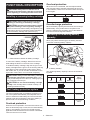 6
6
-
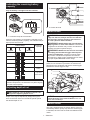 7
7
-
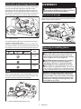 8
8
-
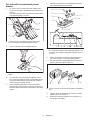 9
9
-
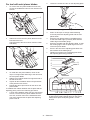 10
10
-
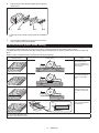 11
11
-
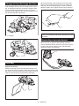 12
12
-
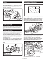 13
13
-
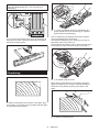 14
14
-
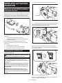 15
15
-
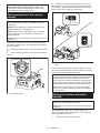 16
16
-
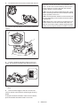 17
17
-
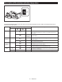 18
18
-
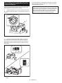 19
19
-
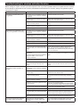 20
20
-
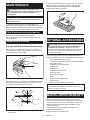 21
21
-
 22
22
-
 23
23
-
 24
24
-
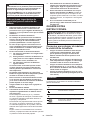 25
25
-
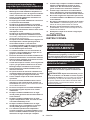 26
26
-
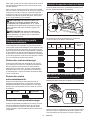 27
27
-
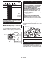 28
28
-
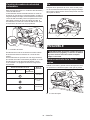 29
29
-
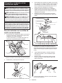 30
30
-
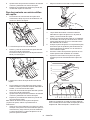 31
31
-
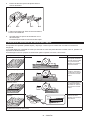 32
32
-
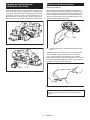 33
33
-
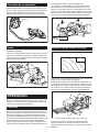 34
34
-
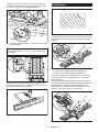 35
35
-
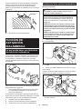 36
36
-
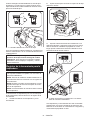 37
37
-
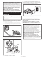 38
38
-
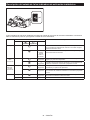 39
39
-
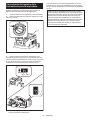 40
40
-
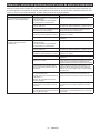 41
41
-
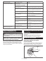 42
42
-
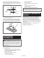 43
43
-
 44
44


Makita XPK02 Manual de usuario
- Categoría
- Cepilladoras eléctricas
- Tipo
- Manual de usuario
- Este manual también es adecuado para
en otros idiomas
- English: Makita XPK02 User manual
Artículos relacionados
-
Makita KP001G Manual de usuario
-
Makita KP0800 Manual de usuario
-
Makita KP0810 Manual de usuario
-
-
Makita XTR01T7-XPK01Z Manual de usuario
-
-
-
-
-