Rockford Fosgate 300SP Installation & Operation Manual
- Categoría
- Amplificadores de audio para automóviles
- Tipo
- Installation & Operation Manual

300SP
400SP
500XP
Installation &
Operation
Instalación y funcionamiento
2-Channel &
4-Channel Amplifiers

INTRODUCTION
TABLE OF CONTENTS
2
Dear Customer,
Congratulations on your purchase of the world's finest brand of car audio amplifiers. At Rockford
Fosgate we are fanatics about musical reproduction at its best, and we are pleased you chose our
product. Through years of engineering expertise, hand craftsmanship and critical testing procedures,
we have created a wide range of products that reproduce music with all the clarity and richness you
deserve.
For maximum performance we recommend you have your new Rockford Fosgate product installed
by an Authorized Rockford Fosgate Dealer, as we provide specialized training through Rockford
Technical Training Institute (RTTI). Please read your warranty and retain your receipt and original
carton for possible future use.
Great product and competent installations are only a piece of the puzzle when it comes to your
system. Make sure that your installer is using 100% authentic installation accessories from
Connecting Punch in your installation. Connecting Punch has everything from RCA cables and
speaker wire to Power line and battery connectors. Insist on it! After all, your new system deserves
nothing but the best.
To add the finishing touch to your new Rockford Fosgate image order your Rockford accessories,
which include everything from T-shirts and jackets to hats and sunglasses.
To get a free brochure on Rockford Fosgate products and Rockford accessories,
in the U.S. call 480-967-3565 or FAX 480-967-8132.
For all other countries, call +001-480-967-3565 or FAX +001-480-967-8132.
PRACTICE SAFE SOUND™
Continuous exposure to sound pressure levels over 100dB may cause permanent
hearing loss. High powered auto sound systems may produce sound pressure
levels well over 130dB. Use common sense and practice safe sound.
Introduction . . . . . . . . . . . . . . . . . . . . . . . . 2
Safety Instructions . . . . . . . . . . . . . . . . . . . 3
Design Features . . . . . . . . . . . . . . . . . . . . 4-5
Installation . . . . . . . . . . . . . . . . . . . . . . 5-11
Installation Considerations . . . . . . . . . . . 5
Mounting Locations. . . . . . . . . . . . . . . . 6
Battery and Charging . . . . . . . . . . . . . . . 6
Wiring the System . . . . . . . . . . . . . . . . . 6
Using Passive Crossovers . . . . . . . . . . . 10
Remote Punch Bass
(300SP & 400SP Only) . . . . . . . . . . . . . 11
NOTE: Review each section for more detailed information.
If, after reading your manual, you still have questions regarding this product, we recommend that
you see your Rockford Fosgate dealer. If you need further assistance, you can call us direct at 1-800-
669-9899. Be sure to have your serial number, model number and date of purchase available when
you call.
The serial number can be found on the outside of the box. Please record it in the space provided
below as your permanent record. This will serve as verification of your factory warranty and may
become useful in recovering your source unit if it is ever stolen.
Serial Number: _________________________________________
Model Number: ________________________________________
Operation. . . . . . . . . . . . . . . . . . . . . . . . . 12
Adjusting Gain . . . . . . . . . . . . . . . . . . 12
Adjusting Crossover Frequency . . . . . . 12
Troubleshooting . . . . . . . . . . . . . . . . . . . . 13
Accessories. . . . . . . . . . . . . . . . . . . . . . . . 13
Specifications . . . . . . . . . . . . . . . . . . . . . . 14
Limited Warranty Information. . . . . . . . . . 15
International Instructions . . . . . . . . . . . . . 16

SAFETY INSTRUCTIONS
CONTENTS OF CARTON
3
Visit our web site for the latest information on all Rockford products.
GETTING STARTED
Welcome to Rockford Fosgate! This manual is designed to provide
information for the owner, salesperson and installer. For those of you who want quick information
on how to install this product, please turn to the Installation Section of this manual. Other
information can be located by using the Table of Contents. We, at Rockford Fosgate, have worked
very hard to make sure all the information in this manual is current. But, as we are constantly
finding new ways to improve our product, this information is subject to change without notice.
www.rockfordfosgate.com
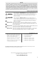
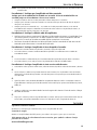
This symbol with “WARNING” is intended to alert the user to the
presence of important instructions. Failure to heed the
instructions will result in severe injury or death.
This symbol with “
CAUTION” is intended to alert the user to the
presence of important instructions. Failure to heed the
instructions can result in injury or unit damage.
CAUTION: To prevent injury and damage to the unit, please read and follow the
instructions in this manual. We want you to have enjoyment from this
system, not a headache.
CAUTION If you feel unsure about installing this system yourself, have it installed
by a qualified Rockford Fosgate technician.
CAUTION Before installation, disconnect the battery negative (-) terminal to
prevent damage to the unit, fire and/or possible injury.
!
!
!
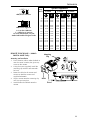
Either a Model 300SP or 400SP Pro 2-
Channel Amplifier or 500XP Pro 4-Channel
Amplifier
Installation & Operation Manual
Mounting Hardware Kit
Remote Punch Bass Kit with Cord
1 High Level Input Harness (300SP & 400SP)
2 High Level Input Harness (500XP)
1 3/32" Allen Wrench
1 9/64" Allen Wrench
1 Fuse Connector
1 30 Amp Fuse (300SP)
1 40 Amp Fuse (400SP)
1 50 Amp Fuse (500XP)
The hardware kit included with each amplifier contains the mounting hardware necessary to secure
the amplifier to the vehicle and to attach the end caps to the amplifier.

4
DESIGN FEATURES
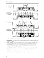
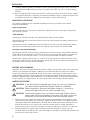
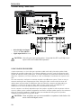
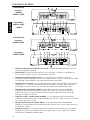
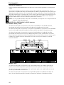
1. LED Power Indicator – The LED illuminates when the unit is turned on.
2. REM Terminal – This spade terminal is used to remotely turn-on and turn-off the amplifier when
+12V DC is applied.
3. Power Terminals – The power and ground connectors on the amplifier are gold-plated and will
accommodate up to 8 AWG wire maximizing the input current capability of the amplifier.
4. Speaker Terminals – The heavy duty, gold-plated terminal block connectors (+ and –) will
accept wire sizes from 8 AWG to 18 AWG. These gold-plated connectors are immune to
corrosion that can cause signal deterioration.
5. Cast Aluminum Heatsink – The cast aluminum heatsink of the Power amplifier dissipates heat
generated by the amplifier's circuitry. The inherent advantage of casting provides a 30%
improvement of cooling over conventional extrusion heatsink designs.
6. Variable Crossover (Models 300SP & 400SP) – Is a built-in 12dB/octave Butterworth filter selectable
for High-Pass (HP), All Pass (AP), or Low-Pass (LP) operation variable from 50Hz to 210Hz.
6. Internal Crossover (Model 500XP) – Is a built-in 12dB/octave Butterworth filter selectable
between 120Hz High-Pass (HP), All Pass (AP), or 80Hz Low-Pass (LP) operation.
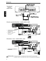
Power
Connections -
Models 300SP
& 400SP
Connections -
Model 500XP
Connections -
Models 300SP
& 400SP
Power
Connections -
Model 500XP

5
DESIGN FEATURES
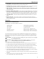
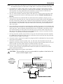
7. Gain Control – The input gain control is preset to match the output of most source units. It can
be adjusted to match output levels from a variety of source units.
8.
RCA Input Jacks – The industry standard RCA jacks provide an easy connection for signal level
input. They are gold-plated to resist the signal degradation caused by corrosion.
9. High Level Inputs – The high level inputs use a detachable connector terminated with 20 AWG
leads. These inputs should be used if the source unit has only speaker line (high level) outputs
and not RCA outputs.
10. Punch Bass (Models 300SP & 400SP) – Helps correct for acoustical deficiencies in the listening
environment by helping produce full range sound without adding excessive boost.. The Punch
Bass control is a narrow band adjustment at 45Hz variable from 0dB to + 18dB. Connection is
made with a cable using RJ-45 and can be installed under the dash for remote control access.
11. Signal Input Switch – This switch allows the amplifier to be driven with either 2 or 4 pairs of
inputs.
12. RCA Pass-Thru Jacks – The Pass-Thru provides a convenient source for daisy-chaining an
additional amplifier without running an extra set of RCA cables from the front of the vehicle to
the rear amplifier location.
INSTALLATION
INSTALLATION CONSIDERATIONS
The following is a list of tools needed for installation:
Volt/Ohm Meter
Wire strippers
Wire crimpers
Wire cutters
#2 Phillips screwdriver
Battery post wrench
Hand held drill w/assorted bits
1/8" diameter heatshrink tubing
Assorted connectors
Adequate Length—Red Power Wire
Adequate Length—Remote Turn-on Wire
Adequate Length—Black Grounding Wire
This section focuses on some of the vehicle considerations for installing your new Amplifier. Pre-
planning your system layout and best wiring routes will save installation time. When deciding on
the layout of your new system, be sure that each component will be easily accessible for making
adjustments.
CAUTION: If you feel unsure about installing this system yourself, have it installed
by a qualified technician.
CAUTION: Before installation, disconnect the battery negative (-) terminal to
prevent damage to the unit, fire and/or possible injury.
Before beginning any installation, follow these simple rules:
1. Be sure to carefully read and understand the instructions before attempting to install the Unit.
2. For safety, disconnect the negative lead from the battery prior to beginning the installation.
3. For easier assembly, we suggest you run all wires prior to mounting your Source Unit in place.
4. Route all of the RCA cables close together and away from any high current wires.
5. Use high quality connectors for a reliable installation and to minimize signal or power loss.
6. Think before you drill! Be careful not to cut or drill into gas tanks, fuel lines, brake or hydraulic
lines, vacuum lines or electrical wiring when working on any vehicle.
7. Never run wires underneath the vehicle. Running the wires inside the vehicle provides the best
protection.
8. Avoid running wires over or through sharp edges. Use rubber or plastic grommets to protect any
wires routed through metal, especially the firewall.
!
!

6
INSTALLA
TION
9. ALWAYS protect the battery and electrical system from damage with proper fusing. Install the
appropriate fuse holder and fuse on the +12V power wire within 18” (45.7 cm) of the battery
terminal.
10. When grounding to the chassis of the vehicle, scrape all paint from the metal to ensure a good,
clean ground connection. Grounding connections should be as short as possible and always be
connected to metal that is welded to the main body, or chassis, of the vehicle.
MOUNTING LOCATIONS
The mounting position of your amplified subwoofer will have a great effect on the sound
performance produced.
Engine Compartment
Never mount this unit in the engine compartment. Mounting the unit in the engine compartment
will void your warranty.
Trunk Mounting
Mounting the amplifier vertically will provide the best cooling of the amplifier.
Mounting the amplifier on the floor of the trunk will work but provides less cooling capability than
vertical mounting.
Mounting the amplifier upside down to the rear deck of the trunk will not provide proper cooling
and will severely affect the performance of the amplifier and is strongly not recommended.
Passenger Compartment Mounting
Mounting the amplifier in the passenger compartment will work as long as you provide a sufficient
amount of air for the amplifier to cool itself. If you are going to mount the amplifier under the seat
of the vehicle, you must have at least 1" (2.54cm) of air gap around the amplifier's heatsink.
Mounting the amplifier with less than 1" (2.54cm) of air gap around the amplifier's heatsink in the
passenger compartment will not provide proper cooling and will severely affect the performance of
the amplifier and is strongly not recommended.
BATTERY AND CHARGING
Amplifiers will put an increased load on the vehicle's battery and charging system. We recommend
checking your alternator and battery condition to ensure that the electrical system has enough
capacity to handle the increased load of your stereo system. Stock electrical systems which are in
good condition should be able to handle the extra load of any Rockford Fosgate amplifier without
problems, although battery and alternator life can be reduced slightly. To maximize the performance
of your amplifier, we suggest the use of a heavy duty battery and an energy storage capacitor.
WIRING THE SYSTEM
CAUTION
: If you do not feel comfortable with wiring your new unit, please see
your local Authorized Rockford Fosgate Dealer for installation.
CAUTION: Before installation, disconnect the battery negative (-) terminal to
prevent damage to the unit, fire and/or possible injury.
CAUTION: Avoid running power wires near the low level input cables, antenna,
power leads, sensitive equipment or harnesses. The power wires carry
substantial current and could induce noise into the audio system.
1. Plan the wire routing. Keep RCA cables close together but isolated from the amplifier's power
cables and any high power auto accessories, especially electric motors. This is done to prevent
coupling the noise from radiated electrical fields into the audio signal. When feeding the wires
through the firewall or any metal barrier, protect them with plastic or rubber grommets to
prevent short circuits. Leave the wires long at this point to adjust for a precise fit at a later time.
2. Prepare the RED wire (power cable) for attachment to the amplifier by stripping 1/2" of
insulation from the end of the wire. Insert the bared wire into the B+ terminal and tighten the set
screw to secure the cable in place.
!
!
!

7
INSTALLA
TION
NOTE: The B+ cable MUST be fused 18" or less from the vehicle's battery. Install the fuseholder under
the hood and prepare the cable ends as stated above. Connections should be water tight.
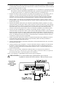
3. Trim the RED wire (power cable) within 18" of the battery and strip1/2"of insulation from the
end of the wire. Cut the wire loop that is attached to the fuseholder in half and splice the fuse
into the power line using appropriate inline connectors. Use the section of cable that was
trimmed earlier and connect it to the other end of the fuseholder.
4. Strip 1/2" from the battery end of the power cable and crimp a large ring terminal to the cable.
Use the ring terminal to connect to the battery positive terminal.
DO NOT install the fuse at
this time.
5. Prepare the BLACK wire (Ground cable) for attachment to the amplifier by stripping 1/2" of
insulation from the end of the wire. Insert the bared wire into the GND terminal and tighten the
set screw to secure the cable in place. Prepare the chassis ground by scraping any paint from
the metal surface and thoroughly clean the area of all dirt and grease. Strip the other end of the
wire and attach a ring connector. Fasten the cable to the chassis using a non-anodized screw
and a star washer.
6. Prepare the REM turn-on wire for connection to the amplifier by stripping 1/2" of insulation from
the wire end. Insert the bared wire into the REM terminal and tighten the set screw to secure the
cable into place. Connect the other end of the REM wire to a switched 12 volt positive source.
The switched voltage is usually taken from the source unit's accessory lead. If the source unit
does not have this output available, the recommended solution is to wire a mechanical switch
in line with a 12 volt source to activate the amplifier.
7. Securely mount the amplifier to the vehicle or amp rack. Be careful not to mount the amplifier
on cardboard or plastic panels. Doing so may enable the screws to pull out from the panel due
to road vibration or sudden vehicle stops.
8. Connect the source signal to the amplifier by plugging the RCA cables/high level inputs into the
input jacks at the amplifier.
9. Connect the speakers. Strip the speaker wires 1/2" and insert into the speaker terminal and
tighten the set screw to secure into place. Be sure to maintain proper speaker polarity. DO NOT
chassis ground any of the speaker leads as unstable operation may result.
10. Perform a final check of the completed system wiring to ensure that all connections are
accurate. Check all power and ground connections for frayed wires and loose connections
which could cause problems.
NOTE: Follow the diagrams for proper signal polarity.
CAUTION: These amplifiers are not recommended for impedance loads below 2Ω
stereo and 4Ω bridged (mono).
!
Power
Connections -
Models 300SP
& 400SP

8
INSTALLA
TION
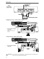
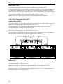
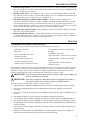
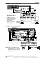
Bridged/Mono Wiring – Models 300SP & 400SP
(L+) White
(L–) White/Black
(R+) Gray
(R–) Gray/Black
High
Level
Input
OR
2-Channel Wiring – Models 300SP & 400SP
(L+) White
(L–) White/Black
(R+) Gray
(R–) Gray/Black
High
Level
Input
OR
Power
Connections -
Model 500XP
• RCA OR High Level input
connection
• RCA OR High Level input
connection
• Gain - left and right set
equally
CAUTION: Use only one input configuration. Using both the RCA and High Level
inputs will cause undesirable operation.
!

9
INSTALLA
TION
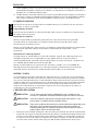
CAUTION: Use only one input configuration. Using both the RCA and High Level
inputs will cause undesirable operation.
!
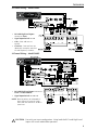
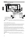
2-Channel Wiring – Model 500XP
• RCA OR High Level Inputs
connect to Front
• Signal Imput Switch set to 2
• Gain - front and rear set
equally
• Crossover - front and rear set
identically (example; switch to
LP and frequency at 60Hz)
3-Channel Wiring – Model 500XP
• RCA OR High Level Inputs connect to
Front or Front and Rear
• Signal Imput Switch set to 2 or 4
NOTE
: Reverse polarity on subwoofer if
front channel is set to HP (High
Pass) and rear channel is set to LP
(Low Pass)

10
INSTALLA
TION
USING PASSIVE CROSSOVERS
A passive crossover is a circuit that uses capacitors and/or coils and is placed on speaker leads
between the amplifier and speaker. The crossover delegates a specific range of frequencies to the
speaker for optimum driver performance. A crossover network can perform one of three functions:
High-Pass (capacitors), Low-Pass (inductors or coils) and Bandpass (combination of capacitor and
coil).
The most commonly used passive crossover networks are 6dB/octave systems. These are easy to
construct and require one component per filter. Placing this filter in series with the circuit will
reduce power to the speaker by 6dB/octave above or below the crossover point depending on
whether it is a high-pass or low-pass filter. More complex systems such as 12dB/octave or
18dB/octave can cause impedance problems if not professionally designed.
Passive crossovers are directly dependent upon the speaker's impedance and component value for
accuracy. When passive crossover components are used in multiple speaker systems, the crossover's
effect on the overall impedance should be taken into consideration along with the speaker's
impedance when determining amplifier loads.
CAUTION: These amplifiers are not recommended for impedance loads below 2Ω
stereo and 4Ω bridged (mono).
!
4-Channel Wiring – Model 500XP
• RCA OR High Level Inputs
connect to Front and Rear
• Signal Imput Switch set to 4
CAUTION: Use only one input configuration. Using both the RCA and High Level
inputs will cause undesirable operation.
!

11
INSTALLA
TION
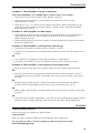
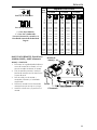
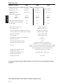
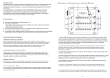
80 4.1mH 1000mF 8.2mH 500mF 16mH 250mF
100 3.1mH 800mF 6.2mH 400mF 12mH 200mF
130 2.4mH 600mF 4.7mH 300mF 10mH 150mF
200 1.6mH 400mF 3.3mH 200mF 6.8mH 100mF
260 1.2mH 300mF 2.4mH 150mF 4.7mH 75mF
400 .8mH 200mF 1.6mH 100mF 3.3mH 50mF
600 .5mH 136mF 1.0mH 68mF 2.0mH 33mF
800 .41mH 100mF .82mH 50mF 1.6mH 26mF
1000 .31mH 78mF .62mH 39mF 1.2mH 20mF
1200 .25mH 66mF .51mH 33mF 1.0mH 16mF
1800 .16mH 44mF .33mH 22mF .68mH 10mF
4000 .08mH 20mF .16mH 10mF .33mH 5mF
6000 51mH 14mF .10mH 6.8mF .20mH 3.3mF
9000 34mH 9.5mF 68mH 4.7mF .15mH 2.2mF
12000 25mH 6.6mF 51mH 3.3mF 100mH 1.6mF
Freq.
Hertz
Speaker Impedance
2 OHMS
8 OHMS
4 OHMS
L L
L
C C
C
6dB/Octave Low-Pass
6dB/Octave High-Pass
L
C
L = Low-Pass (Inductor)
C = High-Pass (Capacitor)
For more information, see your
Authorized Rockford Fosgate Dealer.
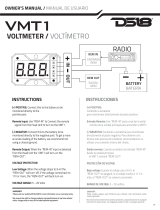
REMOTE PUNCH BASS – (Models
300SP & 400SP Only)
Mounting and installation
1. Find a location, either under the dash or
near the center console, that gives easy
access to the remote.
2. Using the screws supplied, install the
mounting clip with the tabs towards t
he back.
3. Route the cable for the remote and
connect to both the remote and
amplifed subwoofer.
4. Slip the remote onto the mounting clip
until it snaps into place.
5. Install the decal and knob onto the
remote.
Mounting
Clip
Knob
Decal

12
OPERATION
ADJUSTING GAIN
Do the following individually for each channel, or both equally if bridged (mono).
To adjust the gain setting, turn the amplifier gains all the way down. Turn the source unit volume up
until distortion is audible and then turn it down a bit until the distortion is inaudible. This will be
about two thirds all the way up on most source units. Next, turn the amplifier gain setting until once
again distortion is audible and then back it down until the distortion is inaudible. Rockford Fosgate
source units do not distort, so the volume can be used at maximum setting.
NOTE: For a more in depth setting procedure, contact Rockford Technical Support.
ADJUSTING CROSSOVER FREQUENCY
Models 300SP & 400SP
Placing the switch in the HP position sets the amplifier to the High Pass mode, enabling frequencies
above the cut-off point to pass, adjustable between 50-210Hz.
Placing the switch in the AP position sets the amplifier to the All Pass mode, preventing any
crossover adjustment, allowing all frequencies to pass..
Placing the switch in the LP position sets the amplifier to the Low Pass mode, enabling frequencies
below the cut-off point to pass, adjustable between 50-210Hz.
Turn the crossover adjustment knob all the way down. With the system playing, turn the crossover
adjustment knob up slowly until the desired crossover point is achieved.
Model 500XP
Placing the switch in the HP position sets the amplifier to the 120Hz High Pass mode, allowing only
frequencies above the cut-off point to pass.
Placing the switch in the AP position sets the amplifier to the All Pass mode, allowing all
frequencies to pass.
Placing the switch in the LP position sets the amplifier to the 80Hz Low Pass mode, allowing only
frequencies below the cut-off point to pass.

13
TROUBLESHOOTING
NOTE: If you are having problems after installation follow the Troubleshooting procedures below.
Procedure 1: Check Amplifier for proper connections.
Verify that POWER light is on. If POWER light is on skip to Step 2, if not continue.
1. Check in-line fuse on battery positive cable. Replace if necessary.
2. Verify that Ground connection is connected to clean metal of the vehicle’s chassis.
Repair/replace if necessary.
3. Verify there is 10.5 - 15.5 Volts of current present at the positive battery and remote turn-on
cable. Verify quality connections for both cables at amplifier, stereo, and battery/fuseholder.
Repair/replace if necessary.
Procedure 2: Check Amplifier for audio output.
1. Verify good RCA/high-level input connections at stereo and amplifier. Check entire length of
cables for kinks, splices, etc. Test RCA/high-level inputs for AC current with stereo on.
Repair/replace if necessary.
2. Disconnect RCA/high-level input from amplifier. Connect RCA/high-level input from test stereo
directly to amplifier input.
Procedure 3: Check Amplifier if you experience Turn-on Pop.
1. Disconnect input signal to amplifier and turn amplifier on and off.
2. If the noise is eliminated, connect the REM lead of amplifier to source unit with a delay turn-on
module.
OR
1. Use a different 12 Volt source for REM lead of amplifier (i.e. battery direct).
2. If the noise is eliminated, use a relay to isolate the amplifier from noisy turn-on output.
Procedure 4: Check Amplifier if you experience excess Engine Noise.
1. Route all signal carrying wires (RCA, Speaker cables) away from power and ground wires.
OR
2. Bypass any and all electrical components between the stereo and the amplifier(s). Connect
stereo directly to input of amplifier. If noise goes away the unit being bypassed is the cause of
the noise.
OR
3. Remove existing ground wires for all electrical components. Reground wires to different
locations. Verify that grounding location is clean, shiny metal free of paint, rust etc.
OR
4. Add secondary ground cable from negative battery terminal to the chassis metal or engine block
of vehicle.
OR
5. Have alternator and battery load tested by your mechanic. Verify good working order of vehicle
electrical system including distributor, spark plugs, spark plug wires, voltage regulator etc.
ACCESSORIES
Connecting PUNCH Capacitors
Maintain the power you need to your PRO Amplifier.
Connecting Links
Mount your PRO Amplifiers together for space reduction and a smooth look.
See our website for other accessories to help you get the most out of your system.
www.rockfordfosgate.com

14
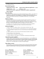
SPECIFICATIONS
Specifications subject to change without notice
MODEL- PRO 300SP 400SP 500XP
Continuous Power Rating (RMS) - Measured at 14.4 Battery Volts
4Ω Load Per Channel 75 Watts x 2 100 Watts x 2 62.5 Watts x 4
2Ω Load Per Channel 150 Watts x 2 200 Watts x 2 125 Watts x 4
4Ω Load Bridged (Mono) 300 Watts x 1 400 Watts x 1 150 Watts x 2
Dimensions: (with Endbell)
Height 2.4" (6.1cm) 2.4" (6.1cm) 2.4" (6.1cm)
Width 9.8" (24.89cm) 9.8" (24.89cm) 9.8" (24.89cm)
Length 11.35" (28.96cm) 12.35" (31.42cm) 13.35" (33.96cm)
Battery Fuse Rating (Amp) 30A 40A 50A
(External to Amplifier)
Fuse Type ATC ATC AGU
Signal-to-Noise Ratio >100dB A-weighted
Crossover Slope 12dB/octave Butterworth
Crossover Frequency (Models 300SP & 400SP) variable from 50Hz to 210Hz
Crossover Frequency (Model 500XP Fixed 80Hz LP, AP, 120Hz HP
Frequency Response 20Hz to 20kHz ±0.5dB
Bandwidth 20Hz to 200kHz ±3dB
Damping Factor @ 4Ω (at output connector ) >200
Slew Rate 30 Volts/ms
IM Distortion (IHF) <0.05%
Acceptable Signal Voltage Range Variable from 250mV to 6V (RCA Input)
Variable from 0.5V to 11V (High Level Input)
Protection NOMAD - Internal analog-computer output protection
circuitry limits power in case of overload. Thermal
switch shuts down the amplifier in case of overheating.
Equalization (45Hz Punch Bass) (Models 150S & 200S) Switchable from 0dB to +6dB to +12dB
Equalization (45Hz Punch Bass) (All Other Models) Variable from 0dB to +18dB @ 45Hz
Input Impedance 20k ohms
The Blue Rockford PCB are exclusive for the PRO Series of Rockford amplifiers.

15
Ship to: Electronics
Rockford Corporation
Warranty Repair Department
2055 E. 5th Street
Tempe, AZ 85281
RA#: _________________________
Ship to: Speakers
Rockford Acoustic Design
Speaker Returns
2356 Turner Ave. NW
Grand Rapids, MI 49544
RA#: ____________________
LIMITED WARRANTY INFORMATION
Rockford Corporation offers a limited warranty on Rockford Fosgate products on the
following terms:
Length of Warranty
PUNCH Amplifiers – 2 years All Other Amplifier Models – 3 years
Source Units – 1 year Speakers – 1 year
90 days on speaker, amplifier and source unit B-stock (receipt required)
What is Covered
This warranty applies only to Rockford Fosgate products sold to consumers by Authorized
Rockford Fosgate Dealers in the United States of America or its possessions. Product
purchased by consumers from an Authorized Rockford Fosgate Dealer in another country
are covered only by that country’s Distributor and not by Rockford Corporation.
Who is Covered
This warranty covers only the original purchaser of Rockford product purchased from an
Authorized Rockford Fosgate Dealer in the United States. In order to receive service, the
purchaser must provide Rockford with a copy of the receipt stating the customer name,
dealer name, product purchased and date of purchase.
Products found to be defective during the warranty period will be repaired or replaced
(with a product deemed to be equivalent) at Rockford's discretion.
What is Not Covered
1. Damage caused by accident, abuse, improper operations, water, theft
2. Any cost or expense related to the removal or reinstallation of product
3. Service performed by anyone other than Rockford or an Authorized Rockford Fosgate
Service Center
4. Any product which has had the serial number defaced, altered, or removed
5. Subsequent damage to other components
6. Any product purchased outside the U.S.
7. Any product not purchased from an Authorized Rockford Fosgate Dealer
Limit on Implied Warranties
Any implied warranties including warranties of fitness for use and merchantability are
limited in duration to the period of the express warranty set forth above. Some states do not
allow limitations on the length of an implied warranty, so this limitation may not apply. No
person is authorized to assume for Rockford Fosgate any other liability in connection with
the sale of the product.
How to Obtain Service
Please call 1-800-669-9899 for Rockford Customer Service. You must obtain an RA#
(Return Authorization number) to return any product to Rockford Fosgate. You are
responsible for shipment of product to Rockford.

2
Español
INTRODUCCIÓN
ÍNDICE DE MATERIAS
Estimado cliente,
Felicitaciones por su compra de la mejor marca del mundo de amplificadores para automóviles. En
Rockford Fosgate somos fanáticos de la mejor reproducción musical y estamos agradecidos de que haya
escogido nuestro producto. Con muchos años de experiencia en ingeniería, conocimiento del oficio y
procedimientos de prueba críticos, hemos creado una amplia gama de productos para reproducción
musical con toda la claridad y la riqueza que usted merece.
Para obtener el mejor rendimiento, le recomendamos que su nuevo producto de Rockford Fosgate
sea instalado por un Distribuidor Autorizado de Rockford Fosgate, puesto que les ofrecemos
capacitación especializada a través del Instituto de Capacitación Técnica Rockford (RTTI). Por favor
lea la garantía, conserve el recibo y la caja original para que los use como posible referencia futura.
Cuando se trata de su sistema, la excelencia del producto y la instalación competente sólo
representan una pieza del rompecabezas. Asegúrese de que la persona que instale su sistema utilice
accesorios 100% auténticos de Connecting Punch. Connecting Punch tiene todos los accesorios
necesarios, desde cables RCA y cableado para altavoces, hasta líneas de alimentación y conectores
de batería. ¡Insista en ello! Después de todo, su nuevo sistema sólo merece lo mejor.
Para darle el toque final a su nueva imagen Rockford Fosgate; pida sus accesorios Rockford, los
cuales incluyen playeras, chaquetas, gorras y anteojos para sol.
Para obtener un folleto gratis de los productos de Rockford Fosgate y accesorios Rockford en los
EE.UU., llame al 480-967-3565 o por FAX 480-967-8132.
Para todos los demás países, llame al +001-480-967-3565 o envíe un FAX al +001-480-967-8132.
PRACTIQUE EL SONIDO SEGURO™
El contacto continuo con niveles de presión de sonido superiores a 100 dB puede
causar la pérdida permanente de la audición. Los sistemas de sonido de alta
potencia para automóviles pueden producir niveles de presión de sonido
superiores a los 130 dB. Aplique el sentido común y practique el sonido seguro
.
NOTA: Lea cada sección para obtener información más detallada.
Si tiene preguntas sobre este producto después de leer el manual, le recomendamos que consulte a
su distribuidor de Rockford Fosgate. Si necesita ayuda adicional, puede llamarnos directamente al
1-800-669-9899. Asegúrese de tener listo el número de la serie, número del modelo y la fecha de
compra cuando llame.
El número de la serie se encuentra en el exterior de la caja. Por favor, escríbalo en el espacio que se
indica a continuación para tener una anotación permanente. Eso servirá como verificación de la
garantía de fábrica y podría ser de utilidad para recuperar su unidad fuente si alguna vez se la
roban.
Número de la serie: _____________________________________
Número del modelo: ____________________________________
Introducción. . . . . . . . . . . . . . . . . . . . . . . . 2
Instrucciones de seguridad . . . . . . . . . . . . . 3
Características del diseño . . . . . . . . . . . . 4-5
Instalación . . . . . . . . . . . . . . . . . . . . . . 5-11
Consideraciones para la instalación . . . . 5
Lugares de montaje . . . . . . . . . . . . . . . . 6
Batería y carga . . . . . . . . . . . . . . . . . . . 6
Cableado del sistema. . . . . . . . . . . . . . . 6
Uso de X-overs pasivos
(Transiciones Pasivas). . . . . . . . . . . . . . 10
Bajo Punch Remoto (Punch Bass)
(300SP y 400SP solamente) . . . . . . . . . 11
Funcionamiento . . . . . . . . . . . . . . . . . . . . 12
Ajuste de ganancia . . . . . . . . . . . . . . . 12
Adjuste de la frecuencia de X-over
(Transición) . . . . . . . . . . . . . . . . . . . . . 12
Solución de problemas . . . . . . . . . . . . . . . 13
Accesorios . . . . . . . . . . . . . . . . . . . . . . . . 13
Especificaciones . . . . . . . . . . . . . . . . . . . . 14
Información sobre la garantía limitada . . . 15

3
INSTRUCCIONES DE SEGURIDAD
CONTENIDO DE LA CAJA
INICIO
¡Bienvenidos a Rockford Fosgate! Este manual ha sido creado para proporcionarle información
al dueño, vendedor y técnico de instalación. Para quienes desean información rápida sobre
cómo instalar este producto, por favor vean la
Sección Instalación de este manual. El resto de la
información puede encontrarse usando el Índice de Materias. Nosotros, en Rockford Fosgate
hemos trabajado arduamente para asegurarnos que toda la información de este manual esté
actualizada. Ya que constantemente encontramos nuevas formas para mejorar nuestros
productos, esta información está sujeta a cambios sin previo aviso.
Este símbolo de “ADVERTENCIA” tiene por objeto alertar al
usuario sobre la presencia de instrucciones de importancia. No
tener en cuenta las instrucciones podría resultar en lesiones
severas o muerte.
Este símbolo de
“PRECAUCIÓN” tiene por objeto alertar al
usuario sobre la presencia de instrucciones de importancia. No
tener en cuenta las instrucciones podría resultar en lesiones o
daños a la unidad.
PRECAUCIÓN: Para prevenir lesiones y daño a la unidad, por favor lea y cumpla las
instrucciones de este manual. Deseamos que disfrute este sistema y no
que sea algo oneroso.
PRECAUCIÓN Si no tiene la certeza de poder instalar el sistema, hágalo instalar por una
persona técnicamente calificada por Rockford Fosgate.
PRECAUCIÓN Antes de la instalación, desconecte el terminal negativo (-) de la batería
para que evite posibles lesiones, daños a la unidad o incendio.
!
!
!
Visite nuestro sitio web para obtener la información más reciente
sobre todos los productos Rockford.
www.rockfordfosgate.com
Bien sea un Amplificador Pro de 2 canales
Modelo 300SP o 400SP o Amplificador
Pro de 4 canales Modelo 500XP
Manual de instalación y funcionamiento
Juego de implementos para el montaje
Juego para el bajo Punch remoto con cable
1 arnés de entrada de alto nivel
1 llave hexagonal de 3/32"
1 llave hexagonal de 9/64"
1 conector de fusibles
1 fusible de 30 amperios (300SP)
1 fusible de 40 amperios (400SP)
1 fusible de 50 amperios (500XP)
El juego de implementos incluidos con cada amplificador contiene lo necesario para fijar el
amplificador en el vehículo y para ponerle las tapas.

4
Español
CARACTERÍSTICAS DEL DISEÑO
1. Diodo electroluminescente indicador de corriente - El diodo electroluminescente se ilumina
cuando la unidad está prendida.
2. Terminal REM - Este terminal de horquilla se usa para apagar y prender el amplificador en
forma remota cuando se le aplica corriente directa + de 12V.
3. Terminales de alimentación de corriente - Los conectores para corriente y tierra del
amplificador están enchapados en oro y se les puede conectar un cable hasta de calibre 8 AWG
maximizando la capacidad de la corriente de entrada del amplificador.
4. Terminales de los altavoces - Los conectores del bloque terminal enchapados en oro y de alto
rendimiento (+ y -) aceptarán tamaños de alambre de 8 AWG a 18 AWG. Estos conectores
enchapados en oro son inmunes a la corrosión que puede causar deterioro de la señal.
5. Disipador térmico de aluminio fundido - El disipador térmico de aluminio fundido del
amplificador Power disipa el calor generado por los circuitos. La ventaja inherente de la
fundición brinda un 30% de refrigeración mejorada sobre los diseños convencionales de
extrusión para disipación térmica.
6. Transición variable (Modelos 300SP & 400SP) – Es un filtro Butterworth incorporado de
24dB/octava seleccionable para funcionamiento de Paso Alto (HP), Todo Paso (AP), o Paso Bajo
(LP) variable, de 50Hz a 210Hz.
6. Filtro de transición interno (Modelo 500XP) – Es un filtro Butterworth incorporado de
24dB/octava, seleccionable para funcionamiento de Paso Alto (HP) a 120Hz, Todo Paso (AP), o
Paso Bajo (LP) a 80Hz.
7. Control de ganancia - el control de ganancia de entrada está precalibrado para que iguale la
salida de la mayoría de las unidades fuente. Se puede ajustar para que iguale los niveles de
salida de una variedad de unidades fuente.
Conexiones -
Modelos 300SP
y 400SP
Conexiones de
corriente -
Modelos
300SP y 400SP
Conexiones -
Modelo 500XP
Conexiones de
corriente -
Modelo 500XP

5
Esta sección se concentra en algunas de las consideraciones para su vehículo para instalar el nuevo
amplificador. La planificación previa del diagrama de su sistema y las mejores rutas del cableado
ayudarán a ahorrar tiempo en la instalación. Cuando se decida sobre el diagrama de su nuevo
sistema, asegúrese de que cada componente esté accesible para realizar ajustes.
PRECAUCIÓN: Si no está seguro sobre cómo instalar el sistema usted mismo, pídale a un
técnico calificado que lo instale.
PRECAUCIÓN: Antes de la instalación, desconecte el terminal negativo de la batería (-)
para prevenir daño a la unidad, incendio y/o posibles lesiones.
Antes de comenzar la instalación, siga estas normas simples:
1. Asegúrese de leer y entender cuidadosamente las instrucciones antes de intentar instalar la unidad.
2. Para mayor seguridad, desconecte el electrodo negativo de la batería antes del comienzo de la
instalación.
3. Para facilitar el montaje, le sugerimos que pase todos los cables antes de montar la unidad fuente en
su lugar.
4. Pase todos los cables RCA juntos y lejos de recorridos de cables de alta corriente.
5. Use conectores de alta calidad para obtener una instalación fiable y reducir la pérdida de potencia.
6. ¡Piense antes de perforar! Tenga cuidado de no cortar o perforar el tanque de combustible, las líneas
de combustible, líneas de frenos o hidráulicas, líneas de vacío o cableado eléctrico cuando trabaje en
cualquier vehículo.
7. Nunca pase los cables por debajo del vehículo. Pasar los cables por el interior del vehículo ofrece la
mejor protección.
8. Evite pasar los cables sobre o por bordes filosos. Use anillos de goma o plástico para proteger los
cables pasados a través del metal, especialmente el muro contra fuego.
!
!
CARACTERÍSTICAS DEL DISEÑO
INSTALACIÓN
CONSIDERACIONES PARA LA INSTALACIÓN
La siguiente es una lista de las herramientas necesarias para la instalación:
Voltímetro / Ohmetro
Pelacables
Tenaza engarzadora de cables
Cortador de cables
Destornillador Phillips No. 2
Llave para bornes de batería
Taladro manual con distintas brocas
Tubo termoretráctil de 1/8 pulgadas de
diámetro
Variedad de conectores
Largo adecuado—Cable rojo para corriente
Largo adecuado—Cable de encendido
remoto
Largo adecuado—Cable negro para
conexión a tierra
8. Enchufes RCA de entrada - Los enchufes RCA normativos en la industria brindan una conexión
fácil para entrada de nivel de la señal. Están enchapados en oro, para resistir la degradación de
la señal causada por la corrosión.
9. Entradas de Alto Nivel – Las entradas de alto nivel usan un conector desprendible, terminado
con cables de calibre 20 AWG. Estas entradas se deben usar si la unidad fuente solamente tiene
cables de salida (alto nivel) del altavoz y no salidas RCA.
5. Bajo Punch (Punch Bass) (Modelos 300SP & 400SP) – Ayuda a corregir las deficiencias
acústicas en el entorno auditivo, al ayudar a producir un sonido de gama completa sin añadir
una sobrealimentación excesiva. El control de bajo Punch es un ajuste de banda estrecha a
45Hz, variable de 0dB a + 18dB. La conexión se hace por medio de un cable RJ-45 y se puede
instalar debajo del tablero de instrumentos, para acceso por control remoto.
11. Interruptor para señal de entrada – Este interruptor permite que el amplificador sea accionado
bien sea 2 o 4 pares de entradas.
12. Enchufes RCA de Paso Directo - El paso directo brinda una fuente conveniente para conectar
un amplificador adicional en cadena, sin tener que conectar otro juego de cables RCA desde el
frente del vehículo hasta el punto del amplificador trasero.

6
Español
INSTALACIÓN
9. Proteja SIEMPRE la batería y el sistema eléctrico contra daños usando los fusibles apropiados. Instale
el portafusible apropiado y el fusible en el cable de +12 V de potencia a una distancia máxima de 18
pulgadas (45,7 cm) del terminal de la batería.
10. Cuando conecte el chasis del vehículo a tierra, quite la pintura del metal para asegurar una conexión a
tierra buena y limpia. Las conexiones de toma de tierra deberán ser las más cortas posibles y deberán
estar siempre conectadas al metal que está soldado al cuerpo principal, o chasis del vehículo.
LUGARES DE MONTAJE
Esta sección se concentra en algunas de las consideraciones para su vehículo que son necesarias
para instalar su nuevo amplificador.
Compartimento del motor
Nunca instale esta unidad en el compartimento del motor. Instalar la unidad en el compartimento
del motor anulará su garantía.
Instalación en el maletero
Montar el amplificador verticalmente proporcionará el mejor enfriamiento al amplificador.
Se puede montar el amplificador en el piso del maletero pero esta posición ofrece menor
enfriamiento que el montaje vertical.
Montar el amplificador boca abajo respecto a la plataforma posterior del maletero no proporcionará
el enfriamiento adecuado, afectará severamente el rendimiento del amplificador y no se
recomienda.
Instalación en la cabina de pasajeros
Se puede montar el amplificador en la cabina de pasajeros, siempre que usted proporcione una
cantidad suficiente de aire al amplificador para que pueda enfriarse. Si planea montar el
amplificador debajo del asiento del vehículo, deberá dejar un espacio mínimo de 1 pulgada (2,54
cm) alrededor del disipador térmico del amplificador.
Montar el amplificador con un espacio de aire menor de 1 pulgada (2,54 cm) alrededor del
disipador térmico del amplificador en la cabina de pasajeros no proporcionará el enfriamiento
apropiado, afectará severamente el rendimiento del amplificador y no se recomienda.
BATERÍA Y CARGA
Los amplificadores incrementarán la demanda de la batería del vehículo y el sistema de carga. Recomendamos
verificar el estado del alternador y de la batería para asegurar que el sistema eléctrico tenga suficiente capacidad
para procesar la demanda adicional en su sistema de estéreo. Sistemas eléctricos de fábrica que están en buenas
condiciones deben tener capacidad suficiente para la demanda adicional de cualquier amplificador de Rockford
Fosgate sin problemas, aunque la vida útil de la batería y del alternador pueden reducirse levemente. Para
maximizar el funcionamiento de su amplificador, le sugerimos que use una batería de gran capacidad y un
condensador para almacenamiento de energía.
CABLEADO DEL SISTEMA
PRECAUCIÓN: Si no se siente capaz de instalar el cableado de su nueva unidad, por favor
consulte a su Distribuidor Autorizado Rockford Fosgate local sobre la instalación.
PRECAUCIÓN: Antes de la instalación, desconecte el terminal negativo de la batería (-) para
prevenir daño a la unidad, incendio o posibles lesiones.
PRECAUCIÓN: Evite pasar los cables de alimentación cerca de los cables de entrada de bajo nivel,
de la antena, de los conductores de alimentación, de equipo sensible o de
cableados preformados. Los cables de alimentación llevan bastante corriente y
podrían inducir ruido en el sistema de audio.
1. Planifique la ruta de cableado. Mantenga los cables RCA juntos pero aislados de los cables de alimentación del
amplificador y de cualquier accesorio del automóvil de alta potencia, especialmente de motores eléctricos. Esto
se hace para evitar ruido de acoplamiento de campos eléctricos irradiantes en la señal de audio. Cuando pase
los cables por el muro contra fuego o por cualquier barrera metálica, protéjalos con anillos de plástico o goma
para evitar cortos circuitos. Deje los cables largos para poder ajustarlos posteriormente en forma precisa.
!
!
!

7
INSTALACIÓN
2. Prepare el cable ROJO (cable para corriente) para conectarlo al amplificador, pelando 1/2 pulgada (1,3 cm) de
la aislación desde el extremo final del cable. Inserte el cable sin aislación en el terminal B+ y ajuste el tornillo de
fijación para asegurar el cable en su lugar.
NOTA: El cable B+ DEBE estar protegido a 18 pulgadas (45,7 cm) de distancia o menos de la batería
del vehículo. Instale el portafusibles debajo del capó y prepare los terminales del cable como
se indicó anteriormente. Las conexiones no deberán permitir la entrada de agua.
3. Recorte el cable ROJO (cable para corriente) a una distancia de 18 pulgadas (45,7 cm) de la batería y pele 1/2
pulgada (1,3 cm) de la aislación del extremo final del cable. Corte el bucle de cable que está unido al
portafusibles a la mitad y empalme el fusible en la línea de alimentación usando los conectores de entrada
correctos. Use la sección de cable que recortó anteriormente y conéctela al otro extremo del portafusibles.
4. Pele 1/2 pulgada (1,3 cm) del cable para corriente del extremo de la batería y engarce a presión un anillo
terminal grande al cable. Use el terminal del anillo para conectar al terminal positivo de la batería. No instale el
fusible en este momento.
5. Prepare el cable NEGRO (cable a tierra) para conectarlo al amplificador, pelando 1/2 pulgada (1,3 cm) de la
aislación del extremo final del cable. Inserte el cable sin aislación en el terminal GND (tierra) y ajuste el tornillo
de fijación para asegurar el cable en su lugar. Prepare la conexión a tierra en el chasis raspando la pintura de la
superficie de metal y limpie minuciosamente el polvo y la grasa del área. Pele el otro extremo del cable y
conecte un anillo conector. Ajuste el cable al chasis con un tornillo no anodizado y una arandela en estrella.
6. Prepare el cable de encendido REM para conectarlo al amplificador, pelando 1/2 pulgada (1,3 cm) de la
aislación del extremo final del cable. Inserte el cable sin aislación dentro del terminal REM y ajuste el tornillo de
fijación para asegurar el cable en su lugar. Conecte el otro extremo del cable REM a una fuente positiva de 12
voltios conmutado. El voltaje conmutado generalmente se toma de la antena o de un conductor accesorio de la
fuente. Si la unidad fuente no tiene estas salidas, se recomienda cablear un interruptor mecánico en línea con
una fuente de 12 voltios para activar el amplificador.
7. Monte el amplificador seguramente al vehículo o al soporte del amplificador. Tenga cuidado de no montar el
amplificador sobre paneles de cartón o plástico porque los tornillos pueden salirse del panel debido a la
vibración o las frenadas repentinas del vehículo.
8. Conecte la señal de la fuente al amplificador, enchufando los cables RCA/entradas de alto nivel a los enchufes
de entrada del amplificador.
9. Conecte los altavoces. Pele 1/2 pulgada (1,3 cm) de los cables de los altavoces, insértelos en los terminales de
los altavoces y ajuste el tornillo de fijación en su lugar. Asegúrese de mantener la polaridad correcta en los
altavoces. NO conecte ninguno de los conductores de los altavoces a tierra, ya que esto puede resultar en un
funcionamiento inestable.
10. Realice un control final del cableado terminado del sistema para asegurarse de que todas las
conexiones son precisas. Verifique que no haya cables pelados ni conexiones sueltas en ninguna de
las conexiones de poder y a tierra que podrían causar problemas.
NOTA: Para establecer la polaridad de señal correcta siga los diagramas.
PRECACUCIÓN:No se recomiendan estos amplificadores para cargas de
impedancia menores de 2Ω en estéreo y 4Ω con puente (mono).
!
Conexión de
corriente -
Modelos 300SP
y 400SP

8
Español
INSTALACIÓN
Cableado con puente/Monofónico – Modelos 300SP y 400SP
Cableado de 2 canales – Modelos 300SP y 400SP
Conexiones de
corriente -
Modelo 500XP
• Conexión de entrada RCA o
de alto nivel
• Conexión de entrada RCA
o de alto nivel
• Ganancia - izquierdo y
derecho puestos
igualmente
PRECAUCIÓN: Solamente utilice una configuración de entrada. El uso de ambas
entradas, la RCA y la de alto nivel, causa un funcionamiento indeseado.
!

9
INSTALACIÓN
PRECAUCIÓN: Solamente utilice una configuración de entrada. El uso de ambas
entradas, la RCA y la de alto nivel, causa un funcionamiento indeseado.
!
Cableado de 2 canales – Modelo 500XP
• Las entradas RCA o de Alto
Nivel se conectan al Frente
• Interruptor para señal de
entrada puesto en 2
• Ganancia - delantero y
trasero puestos igualmente
•
Transición - delanteros y
traseros puestos
idénticamente (Ejemplo,
cambia a LP y la
frecuencia a 60Hz)
Izquierdo
con puente
Derecho
con puente
Cableado de 3 canales – Modelo 500XP
• Las entradas RCA o las de Alto Nivel se
conectan al Frente o al Frente y Atrás
• Interruptor para señal de entrada
puesto en 2 o 4
NOTA: Invierta la polaridad del altavoz
para sonidos graves si el canal del
frente está puesto en HP (Paso Alto)
y el canal trasero está puesto en LP
(Paso Bajo)
Con
puente

10
Español
USO DE X-OVERS PASIVOS (Transiciones Pasivas)
Un X-over pasivo es un circuito que usa condensadores y/o bobinas, el cual se coloca en los conductores de los
altavoces entre el amplificador y el altavoz. El X-over delega una gama específica de frecuencias al altavoz para
un funcionamiento óptimo del transductor electroacústico. Una red de X-over puede realizar una de tres
funciones: Paso alto (condensadores), paso bajo (inductores o bobinas) y paso de banda (combinación de
condensador y bobina).
Las redes de X-over pasivo más comúnmente usadas son los sistemas de 6 dB/octava. Estos son fáciles de
construir y requieren un componente por filtro. Si se coloca este filtro en serie con el circuito, la potencia al
amplificador se reducirá en 6 dB/octava por arriba o por debajo del punto de X-over, dependiendo de si es un
filtro de paso alto o de paso bajo. Los sistemas más complejos como los de 12 dB/octava o 18 dB/octava pueden
causar problemas de impedancia si no están diseñados profesionalmente.
La exactitud de los X-overs pasivos depende directamente de la impedancia y del valor del componente del
altavoz. Cuando se utilizan componentes X-over pasivos en sistemas de altavoces múltiples, se deberá tomar en
cuenta el efecto de X-over sobre la impedancia total junto con la impedancia del altavoz al determinar las cargas
del amplificador.
PRECACUCIÓN:No se recomiendan estos amplificadores para cargas de
impedancia menores de 2Ω en estéreo y 4Ω con puente (mono).
!
INSTALACIÓN
Cableado de 4 canales – Modelo 500XP
• Las entradas RCA o de Alto Nivel
se conectan al Frente y Atrás
• Interruptor para señal de entrada
puesto en 4
PRECAUCIÓN: Solamente utilice una configuración de entrada. El uso de ambas
entradas, la RCA y la de Alto Nivel, causa un funcionamiento indeseado.
!

11
80 4.1mH 1000mF 8.2mH 500mF 16mH 250mF
100 3.1mH 800mF 6.2mH 400mF 12mH 200mF
130 2.4mH 600mF 4.7mH 300mF 10mH 150mF
200 1.6mH 400mF 3.3mH 200mF 6.8mH 100mF
260 1.2mH 300mF 2.4mH 150mF 4.7mH 75mF
400 .8mH 200mF 1.6mH 100mF 3.3mH 50mF
600 .5mH 136mF 1.0mH 68mF 2.0mH 33mF
800 .41mH 100mF .82mH 50mF 1.6mH 26mF
1000 .31mH 78mF .62mH 39mF 1.2mH 20mF
1200 .25mH 66mF .51mH 33mF 1.0mH 16mF
1800 .16mH 44mF .33mH 22mF .68mH 10mF
4000 .08mH 20mF .16mH 10mF .33mH 5mF
6000 51mH 14mF .10mH 6.8mF .20mH 3.3mF
9000 34mH 9.5mF 68mH 4.7mF .15mH 2.2mF
12000 25mH 6.6mF 51mH 3.3mF 100mH 1.6mF
INSTALACIÓN
Freq.
Hertz
Impedancia del altavoz
2 OHMS
8 OHMS
4 OHMS
L L
L
C C
C
Paso bajo de 6dB/octava
Paso alto de 6dB/octava
L
C
L = Paso bajo (Inductor)
C = Paso alto (condensador)
Para más información, consulte a su
Distribuidor Autorizado de Rockford
Fosgate.
BAJO PUNCH REMOTO (Punch Bass)–
(Modelos 300SP y 400SP solamente)
Montaje e instalación
1. Encuentre un lugar debajo del tablero o
cerca del centro de la consola, el cual
permita acceder fácilmente al remoto.
2. Con los tornillos provistos, instale el
broche de montaje con las aletas hacia
la parte de atrás.
3. Pase el cable para el remoto y
conéctelo al remoto y al subwoofer
amplificado.
4. Deslice el remoto hacia el broche de
montaje hasta que encaje en su lugar.
5. Instale la calcomanía y la perilla en el
remoto.
Broche de
montaje
Perilla
Calcomanía

12
Español
FUNCIONAMIENTO
Modelo 500XP
Al colocar el interruptor en la posición HP el amplificador queda en el modo de Paso Alto de
120Hz, lo cual solamente permite el paso de las frecuencias superiores al punto de transición.
Al colocar el interruptor en la posición AP, el amplificador queda en el modo Todo Paso, lo cual
permite el paso de todas las frecuencias.
Al colocar el interruptor en la posición LP el amplificador queda en el modo de Paso Bajo de
80Hz, lo cual solamente permite el paso de las frecuencias inferiores al punto de transición.
AJUSTE DE GANANCIA
Haga lo siguiente independientemente con cada canal, o con ambos igualmente, si tienen puente
(mono).
Para ajustar el valor de la ganancia, baje la ganancia del amplificador completamente. Suba el
volumen de la unidad fuente hasta que la distorsión sea audible y luego bájelo un poco hasta que la
distorsión no pueda escucharse. En la mayoría de las fuentes, esto ocurrirá a aproximadamente dos
tercios del volumen total. A continuación, suba la ganancia del amplificador nuevamente hasta que
la distorsión sea audible y luego bájela hasta que sea inaudible. Las unidades fuentes Rockford
Fosgate no distorsionan. Por eso, el volumen puede usarse al máximo.
NOTA: Para un procedimiento de calibración más detallado, comuníquese con el Departamento de
Asistencia Técnica de Rockford.
AJUSTE DE LA FRECUENCIA X-OVER (Transición)
Modelos 300SP y 400SP
Al colocar el interruptor en la posición HP se pone al amplificador en el modo de Paso Alto,
permitiendo el paso de las frecuencias del punto de corte, ajustable entre 50-210Hz.
Al colocar el interruptor en la posición AP, se pone el amplificador en la posición en el modo Todo
Paso, lo cual impide cualquier ajuste de transición y permite que todas las frecuencias pasen.
Al colocar el interruptor en la posición LP se pone el amplificador en el modo de Paso Bajo,
permitiendo el paso de las frecuencias por debajo del punto de corte, ajustable entre 50-210Hz.
Gire el botón para ajuste de transición completamente hacia abajo. Ponga a sonar el sistema y gire
el botón para ajuste de transición lentamente hacia arriba, hasta que se obtenga el punto de
transición deseado.

13
SOLUCIÓN DE PROBLEMAS
NOTA: Si tiene problemas después de la instalación, siga los procedimientos de solución de problemas descritos
a continuación.
Procedimiento 1: Verifique que el amplificador esté bien conectado.
Verifique que la luz de ALIMENTACIÓN (POWER) esté encendida. Si la luz de ALIMENTACIÓN está
encendida prosiga con el Procedimiento 2. De no ser así, continúe.
1. Verifique el fusible en línea en el cable positivo de la batería. Reemplace si es necesario.
2. Verifique que la conexión a tierra esté conectada a un área de metal limpia del chasis del vehículo. Repare o
reemplace si es necesario.
3. Verifique que haya una corriente de 10,5 – 15,5 volteos en el cable positivo de la batería y en el cable de
encendido remoto. Verifique la calidad de las conexiones de ambos cables en el amplificador, el estéreo y la
batería/portafusibles. Repare o reemplace si es necesario.
Procedimiento 2: Verifique la salida de audio del amplificador.
1. Verifique que haya buenas conexiones RCA/de alto nivel de entrada en el estéreo y el amplificador. Fíjese
que no haya pellizcos, empalmes, etc. en todo el largo de los cables. Pruebe las entradas RCA/de alto
nivel para la CA actual con el estéreo encendido. Repare o reemplace si es necesario.
2. Desconecte la entrada RCA/de alto nivel del amplificador. Conecte la entrada de RCA/de alto nivel del
estéreo de prueba directamente a la entrada del amplificador.
Procedimiento 3: Verifique el amplificador si tiene chasquidos al encender.
1. Desconecte la señal de entrada al amplificador y encienda y apague el amplificador.
2. Si el ruido se elimina, conecte el conductor REM del amplificador a la unidad fuente con un módulo de
encendido de retardo.
O
1. Use una fuente de 12 volteos distinta para el conductor REM del amplificador (ejemplo, directo a la batería).
2. Si el ruido se elimina, use un relé para aislar el amplificador del la salida de encendido ruidosa.
Procedimiento 4: Verifique el amplificador si siente excesivo ruido de motor.
1. Pase todos los cables que llevan señales (RCA, cables de altavoces) lejos de los cables de alimentación y de tierra.
O
2. Desvíe cualquiera y todos los componentes eléctricos entre el estéreo y los amplificadores. Conecte el estéreo
directamente a la entrada del amplificador. Si el ruido desaparece el componente que está siendo desviado es la
causa del ruido.
O
3. Quite los cables a tierra existentes de todos los componentes eléctricos. Vuelva a conectarlos a tierra en
lugares diferentes. Verifique que el sitio de conexión a tierra esté limpio, que sea metal brilloso sin pintura,
óxido, etc.
O
4. Añada un cable a tierra secundario desde el terminal negativo de la batería al chasis de metal o al bloque
del motor del vehículo.
O
5. Haga que su mecánico pruebe la carga del alternador y la batería. Verifique que el sistema eléctrico del vehículo
esté en orden, incluyendo el distribuidor, las bujías, los cables de las bujías, el regulador de voltaje, etc.
ACCESORIOS
Capacitores conectores PUNCH
Mantienen la corriente que usted necesita para su amplificador de PRO.
Conexión de acoples
Monte sus amplificadores de PRO juntos, para reducir el espacio y para que se vean bien.
Visite nuestro sitio en la red en busca de otros accesorios, para ayudarle a obtener el mejor
provecho de su sistema.
www.rockfordfosgate.com

14
Español
ESPECIFICACIONES
Estas especificaciones están sujetas a cambio sin previo aviso
MODELO - PUNCH 300SP 400SP 500XP
Clasificación de potencia continua (Valor eficaz) – Medida a 14.4 voltios en la batería
4 Ω-Carga por canal 75 vatios x 2 100 vatios x 2 62,5 vatios x 4
2Ω Carga por canal 150 vatios x 2 200 vatios x 2 125 vatios x 4
4 Ω-arga con puente 300 vatios x 1 400 vatios x 1 150 vatios x 2
(Monofónica)
Dimensiones: (con terminador)
Altura 6,1 cm 6,1 cm 6,1 cm
Anchura 24,89 cm 24,89 cm 24,89 cm
Longitud 28,96 cm 31,42 cm 33,96cm
Clasificación de fusibles de la batería 30 A 40 A 50 A
(Amperios) (Externos al amplificador)
Tipo de fusible ATC ATC AGU
Relación entre ruido y señal >100dB ponderado A
Declive de transición 12dB/octava Butterworth
Frecuencia de transición (Modelos 150S y 200S) Fija 80Hz LP, AP, 120Hz HP
Frecuencia de transición (Todos los demás modelos) variable de 50Hz a 210Hz
Frecuencia de respuesta 20Hz a 20kHz ±0.5dB
Ancho de banda 20Hz a 200kHz ±3dB
Decrecimiento a 4Ω (en el conector de salida) >200
Rapidez de respuesta 30 Voltios/ms
Distorsión de intermodulación (IHF) <0.05%
Señal aceptable de gama de voltaje Variable de 250mV a 6V (Entrada RCA)
Variable de 0.5V a 11V (Entrada de alto nivel)
Protección: NOMAD – El circuito de computador análogo interno de salida
limita la corriente en caso de sobrecarga. El interruptor térmico
apaga el amplificador en caso de recalentamiento.
Compensación (45Hz Bajo Punch) Cambiable de 0dB a +6dB a +12dB
(Modelos 150S & 200S)
Compensación (45Hz Bajo Punch) Variable de 0dB a +18dB a 45Hz
(Todos los demás modelos)
Impedancia de entrada. 20k ohmios
La tarjeta de circuitos impresos Blue Rockford es exclusiva de la serie de amplificadores PRO de
Rockford

15
INFORMACIÓN SOBRE LA GARANTÍA LIMITADA
Enviar a: Electronics
Rockford Corporation
Warranty Repair Department
2055 E. 5th Street
Tempe, AZ 85281
RA#: _________________________
Enviar a: Speakers
Rockford Acoustic Design
Speaker Returns
2356 Turner Ave. NW
Grand Rapids, MI 49544
RA#: ____________________
Rockford Corporation ofrece una garantía limitada para los productos Rockford Fosgate bajo
los siguientes términos:
Duración de la garantía
Amplificadores PUNCH – 2 años Todos los demás modelos de amplificadores – 3 años
Unidades fuente – 1 año Altavoces – 1 año
90 días para los altavoces, amplificador y unidad fuente surtido-B (comprobante de
compra requerido)
Qué está cubierto
Esta garantía se aplica solamente a los productos Rockford Fosgate vendidos a consumidores por
Concesionarios Autorizados Rockford Fosgate en los Estados Unidos o sus posesiones. Los
productos comprados por los consumidores en un Distribuidor Autorizado Rockford Fosgate de
otro país están cubiertos solamente por el Distribuidor de dicho país y no por Rockford
Corporation.
Quién está cubierto
Esta garantía cubre solamente al comprador original del producto Rockford comprado en un
Concesionario Autorizado de Rockford Fosgate de los Estados Unidos. Para poder recibir el
servicio, el comprador debe presentarle a Rockford una copia del recibo indicando el nombre
del cliente, nombre del distribuidor, producto comprado y la fecha de la compra.
Los productos que estén defectuosos durante el período de la garantía serán arreglados o
reemplazados (con un producto equivalente) a entera discreción de Rockford.
Qué no está cubierto
1. Daños causados por accidentes, abusos, funcionamiento inadecuado, agua, robo
2. Cualquier costo o gasto relacionado con la desinstalación o nueva instalación del producto
3. Servicios prestados por alguien que no sea un Centro de Servicio Autorizado por Rockford
Fosgate
4. Cualquier producto que tenga el número de serie borrado, alterado o removido
5. Daños posteriores a otros componentes
6. Cualquier producto comprado fuera de los EE.UU.
7. Cualquier producto no comprado en un Distribuidor Autorizado de Rockford Fosgate
Límite de las garantías implícitas
Cualquier garantía implícita incluyendo las garantías de aptitud de uso y comerciabilidad, está
limitada, en duración al período de la garantía expresa indicada anteriormente. Algunos estados
no permiten limitaciones en la duración de una garantía implícita, de modo que esta limitación
puede no aplicarse. Ninguna persona está autorizada a adoptar ninguna otra obligación en
conexión con la venta del producto en nombre de Rockford Fosgate.
Cómo obtener servicio
Por favor, llame al 1-800-669-9899 para obtener Servicio al Cliente de Rockford. Debe obtener
un # NADM (Número de Autorización para la Devolución del Material) para enviar cualquier
producto a Rockford Fosgate. Usted es responsable por el envío del producto a Rockford.

16
Español
NOTA

17
NOTA

12/01 B.M.
MAN-4010-A
Printed in U.S.A
Rockford Fosgate
Rockford Corporation
546 South Rockford Drive
Tempe, Arizona 85281 U.S.A.
In U.S.A., (480) 967-3565
In Europe, Fax (49) 8503-934014
In Japan, Fax (81) 559-79-1265
www.rockfordfosgate.com
-
 1
1
-
 2
2
-
 3
3
-
 4
4
-
 5
5
-
 6
6
-
 7
7
-
 8
8
-
 9
9
-
 10
10
-
 11
11
-
 12
12
-
 13
13
-
 14
14
-
 15
15
-
 16
16
-
 17
17
-
 18
18
-
 19
19
-
 20
20
-
 21
21
-
 22
22
-
 23
23
-
 24
24
-
 25
25
-
 26
26
-
 27
27
-
 28
28
-
 29
29
-
 30
30
-
 31
31
-
 32
32


Rockford Fosgate 300SP Installation & Operation Manual
- Categoría
- Amplificadores de audio para automóviles
- Tipo
- Installation & Operation Manual
en otros idiomas
- English: Rockford Fosgate 300SP
Artículos relacionados
-
 Rockford Fosgate 75 Manual de usuario
-
 Rockford Fosgate RFT3101A Manual de usuario
-
 Rockford Fosgate RFT3101A Manual de usuario
-
 Rockford Fosgate Punch P850.4 Guía de instalación
-
 Rockford Fosgate Punch P8004 Instrucciones de operación
-
Rockford Fosgate PBR300X4 El manual del propietario
-
 Rockford Fosgate Pro Series bd1001P Instrucciones de operación
-
 Rockford Fosgate t 600 4 El manual del propietario
-
 Rockford Fosgate Power 351M Manual de usuario
-
 Rockford Fosgate T400-2 Manual de usuario


Otros documentos
-
Prime R500-1D Installation & Operation Manual
-
Blaupunkt PCA450 Manual de usuario
-
 Lightning Audio Storm X1.2000.1D Manual de usuario
-
Dual BAK1000 Manual de usuario
-
Lightning Audio Strike S4.400.4 Installation & Operation Manual
-
 Boss Audio Systems EQ600 El manual del propietario
-
 DS18 VMT1 Instrucciones de operación


