Cafe 1067756 Guía de instalación

Tipo
Guía de instalación
READ CAREFULLY.
KEEP THESE INSTRUCTIONS
.
31-2000103 09-18 GEA
LA SECCIÛN EN ESPAÒOL
EMPIEZA EN LA P·GINA 25.
Over the Range
Microwave Oven
Installation
Instructions
BEFORE YOU BEGIN
Read these instructions carefully and completely.
Ŷ IMPORTANTSave these instructions for
local inspector’s use.
Ŷ IMPORTANTObserve all governing codes
and ordinances.
Ŷ Note to Installer – Be sure to leave these instructions
with Consumer.
Ŷ Note to Consumer – Keep these instructions for
future reference.
Ŷ Skill level – Installation of this appliance requires
basic mechanical and electrical skills.
Ŷ 3URSHULQVWDOODWLRQLVWKHUHVSRQVLELOLW\RIWKHLQVWDOOHU
Ŷ 3URGXFWIDLOXUHGXHWRLPSURSHULQVWDOODWLRQLVQRW
FRYHUHGXQGHU:DUUDQW\
2
Outside Back Exhaust ............................16-19
3UHSDULQJ5HDU:DOOIRU
Outside Back Exhaust ........................16
$WWDFK0RXQWLQJ3ODWHWR:DOO .......16 17
3UHSDUDWLRQRI7RS&DELQHW ................17
Adapting Microwave Blower
for Outside Back Exhaust ............. 17, 18
Mount the Microwave Oven ............... 19
5HFLUFXODWLQJ ......................................... 20-23
$WWDFK0RXQWLQJ3ODWHWR:DOO ........... 20
3UHSDUDWLRQRI7RS&DELQHW ............... 20
Check Blower Motor Orientation ........ 21
Adapting Microwave Blower
IRU5HFLUFXODWLRQ ........................... 21, 22
Mount the Microwave Oven ......... 22, 23
Installing the Charcoal Filter .............. 23
Before You Use Your Microwave ...................... 24
CONTENTS
General information
Important Safety Instructions .............................. 3
Electrical Requirements ........................................ 3
Hood Exhaust .................................................... 4, 5
Damage – Shipment/Installation .......................... 6
Parts Included ........................................................ 6
Tools You Will Need .............................................. 7
Mounting Space ..................................................... 7
Step-by-step Installation Guide
Placement of Mounting Plate ......................... 8–10
5HPRYLQJWKH0RXQWLQJ3ODWH ...................... 8
Finding the Wall Studs ................................. 8
'HWHUPLQLQJ:DOO3ODWH/RFDWLRQ .................. 9
$OLJQLQJWKH:DOO3ODWH ............................... 10
Installation Types .......................................... 11–23
2XWVLGH7RS([KDXVW ............................ 12–15
$WWDFK0RXQWLQJ3ODWHWR:DOO ............12
3UHSDUDWLRQRI7RS&DELQHW ................13
Check Blower Motor Orientation .........13
Adapting Blower for Outside
Ventilation .....................................13, 14
&KHFNIRU3URSHU'DPSHU
Operation ............................................14
Mount the Microwave Oven ..........14, 15
Adjust the Exhaust Adaptor ................15
Connecting Ductwork .......................... 15
A
C
Installation Instructions
B
3
IMPORTANT SAFETY INSTRUCTIONS
A qualified electrician must perform a ground
FRQWLQXLW\FKHFNRQWKHZDOOUHFHSWDFOHEHIRUH
beginning the installation to ensure that the
RXWOHWER[LVSURSHUO\JURXQGHG,IQRWSURSHUO\
grounded, or if the wall receptacle does not meet
HOHFWULFDOUHTXLUHPHQWVQRWHGXQGHU(/(&75,&$/
5(48,5(0(176DTXDOLILHGHOHFWULFLDQVKRXOGEH
HPSOR\HGWRFRUUHFWDQ\GHILFLHQFLHV
Risk of Electric Shock.
Can cause injury or
death: Remove house
fuse or
open circuit breaker
before beginning
installation to avoid
severe or fatal shock
injury.
Risk of Electric
Shock. Can cause
injury or death: THIS
APPLIANCE MUST
BE PROPERLY
GROUNDED to avoid
severe or fatal shock.
The power cord of this appliance is equipped
with a three-prong (grounding) plug which mates
with a standard three-prong (grounding) wall
receptacle to minimize the possibility of electric
shock hazard from this appliance.
Where a standard two-prong wall receptacle is
encountered, it must be replaced with a properly
grounded three-prong wall receptacle, installed by
a qualified electrician.
Installation Instructions
Ensure
proper
ground
exists before
use
FOR YOUR SAFETY:
For personal safety,
the mounting surface must be
capable of supporting the cabinet load, in addition to
the added weight of this 63–85 pound product, plus
additional oven loads of up to 50 pounds or a total
weight of 113–135 pounds.
For personal safety, this product
cannot be installed in cabinet
arrangements such as an island or a peninsula. It must
EHPRXQWHGWR%27+DWRSFDELQHW$1'DZDOO
To avoid the risk of personal
injuryEDFNLQMXU\RURWKHULQMXULHV
GXHWRH[FHVVLYHZHLJKWRIWKHPLFURZDYHRYHQRU
SURSHUW\GDPDJH\RXZLOOQHHGWZRSHRSOHWRLQVWDOO
this microwave oven.
ELECTRICAL REQUIREMENTS
3URGXFWUDWLQJLVYROWV$&+HUW]
DPSVDQGNLORZDWWV7KLVSURGXFWPXVWEH
FRQQHFWHGWRDVXSSO\FLUFXLWRIWKHSURSHUYROWDJH
DQGIUHTXHQF\:LUHVL]HPXVWFRQIRUPWRWKH
UHTXLUHPHQWVRIWKH1DWLRQDO(OHFWULFDO&RGHRUWKH
SUHYDLOLQJORFDOFRGHIRUWKLVNLORZDWWUDWLQJ7KH
SRZHUVXSSO\FRUGDQGSOXJVKRXOGEHEURXJKWWR
a separate 15- to 20-ampere branch circuit single
JURXQGHGRXWOHW7KHRXWOHWER[VKRXOGEHORFDWHG
LQWKHFDELQHWDERYHWKHPLFURZDYHRYHQ7KH
RXWOHWER[DQGVXSSO\FLUFXLWVKRXOGEHLQVWDOOHGE\
DTXDOLILHGHOHFWULFLDQDQGFRQIRUPWRWKH1DWLRQDO
Electrical Code or the prevailing local code.
CAUTION
CAUTION
CAUTION
RISK OF ELECTRIC SHOCK
Can cause injury or death: DO
NOT, under any circumstances,
cut, deform or remove any of the prongs from the
power cord. Do not use with an extension cord.
Failure to comply may cause fire.
WARNING
WARNING
WARNING
4
HOOD EXHAUST
7KHIROORZLQJFKDUWGHVFULEHVDQH[DPSOHRIRQHSRVVLEOH
ductwork installation.
127(5HDGWKHVHQH[WWZRSDJHVRQO\LI\RXSODQWRYHQW\RXUH[KDXVWWRWKHRXWVLGH,I\RXSODQWRUHFLUFXODWHWKHDLUEDFN
into the room,
proceed to page 11.
OUTSIDE TOP EXHAUST (EXAMPLE ONLY)
NOTE: For back exhaust, care should be taken to align exhaust with space between studs, or wall
VKRXOGEHSUHSDUHGDWWKHWLPHLWLVFRQVWUXFWHGE\OHDYLQJHQRXJKVSDFHEHWZHHQWKHZDOOVWXGVWR
accommodate exhaust.
* IMPORTANT: If a rectangular-to-round transition adaptor is used, the bottom corners of the damper
will have to be cut to fit, using the tin snips, in order to allow free movement of the damper.
7KHIROORZLQJFKDUWGHVFULEHVDQH[DPSOHRIRQHSRVVLEOH
ductwork installation.
Installation Instructions
OUTSIDE BACK EXHAUST (EXAMPLE ONLY)
EQUIVALENT NUMBER
DUCT PIECES LENGTH x USED = LENGTH
5RRI&DS )W [  )W
)W6WUDLJKW'XFW )W [  )W
(6s5RXQG
5HFWDQJXODUWR5RXQG )W [  )W
7UDQVLWLRQ$GDSWRU
Equivalent lengths of duct pieces are based on actual tests and
UHIOHFWUHTXLUHPHQWVIRUJRRGYHQWLQJSHUIRUPDQFHZLWKDQ\YHQWKRRG
Total Length = 41 Ft.
EQUIVALENT NUMBER
DUCT PIECES LENGTH* x USED = LENGTH
:DOO&DS )W [  )W
)W6WUDLJKW'XFW )W [  )W
(3
1
»4s x 10s5HFWDQJXODU
(OERZ )W [  )W
Equivalent lengths of duct pieces are based on actual tests and
UHIOHFWUHTXLUHPHQWVIRUJRRGYHQWLQJSHUIRUPDQFHZLWKDQ\YHQWKRRG
Total Length = 63 Ft.
5
EQUIVALENT NUMBER
DUCT PIECES LENGTH x USED = LENGTH
5HFWDQJXODUWR5RXQG )W [  )W
7UDQVLWLRQ$GDSWRU
:DOO&DS )W [  )W
(OERZ )W [  )W
(OERZ )W [  )W
(OERZ )W [  )W
(OERZ )W [  )W
5RRI&DS )W [  )W
Straight Duct 6s5RXQGRU )W [  )W
3
1
»4s x 10s5HFWDQJXODU
Total Ductwork = Ft.
Equivalent lengths of duct pieces are based on actual tests
and reflect requirements for good venting performance with
DQ\YHQWKRRG
IMPORTANT: If a rectangular-to-round transition
adaptor is used, the bottom corners of the
damper will have to be cut to fit, using the tin
snips, in order to allow free movement of the
damper
.
Installation Instructions
NOTE: ,I\RXQHHGWRLQVWDOOGXFWVQRWHWKDWWKHWRWDO
duct length of 3
1
»4Ǝ[ƎUHFWDQJXODURUƎGLDPHWHUURXQG
duct should not exceed 140 equivalent feet.
2XWVLGHYHQWLODWLRQUHTXLUHVD+22'(;+$867'8&7
5HDGWKHIROORZLQJFDUHIXOO\
NOTE: It is important that venting be installed using
the most direct route and with as few elbows as possible.
7KLVHQVXUHVFOHDUYHQWLQJRIH[KDXVWDQGKHOSVSUHYHQW
blockages. Also, make sure dampers swing freely and
nothing is blocking the ducts.
Exhaust connection:
7KHKRRGH[KDXVWKDVEHHQGHVLJQHGWRPDWHZLWK
a standard 3
1
»4Ǝ[ƎUHFWDQJXODUGXFW
If a round duct is required, a rectangular-to-round
transition adaptor must be used. Do not use less than
a 6Ǝ diameter duct.
Maximum duct length:
)RUVDWLVIDFWRU\DLUPRYHPHQWWKHWRWDOGXFWOHQJWKRI
3
1
»4s x 10s rectangular or 6s diameter round duct should
not exceed 140 equivalent feet.
Elbows, transitions, wall and roof caps,
etc., present additional resistance to airflow and are
equivalent to a section of straight duct which is longer
WKDQWKHLUDFWXDOSK\VLFDOVL]H:KHQFDOFXODWLQJWKHWRWDO
duct length, add the equivalent lengths of all transitions
and adaptors plus the length of all straight duct sections.
7KHFKDUWEHORZVKRZV\RXKRZWRFDOFXODWHWRWDO
equivalent ductwork length using the approximate feet of
HTXLYDOHQWOHQJWKRIVRPHW\SLFDOGXFWV
6
HARDWARE PACKET
PART QUANTITY
7RS&DELQHW
1
7HPSODWH
5HDU:DOO
7HPSODWH
Installation 1
Instructions
6HSDUDWHO\
2
3DFNHG
Grease
Filter
PART QUANTITY
Wood Screws 2
(
1
»4s x 2s
 7RJJOH%ROWVDQG 
ZLQJQXWV
(
3
»16s x 3s
Self-Aligning
Machine
Screws 3
(
1
»4s-28 x 3
1
»4s
1\ORQ*URPPHW
IRUPHWDOFDELQHWV
DAMAGE – SHIPMENT INSTALLATION
If the unit is damaged in shipment, return the
unit to the store in which it was bought for repair or
replacement.
If the unit is damaged by the customer, repair or
UHSODFHPHQWLVWKHUHVSRQVLELOLW\RIWKHFXVWRPHU
If the unit is damaged by the installer (if other
WKDQWKHFXVWRPHUUHSDLURUUHSODFHPHQWPXVW
EHPDGHE\DUUDQJHPHQWEHWZHHQFXVWRPHUDQG
installer.
PARTS INCLUDED
You will find the installation hardware contained in a
SDFNHWZLWKWKHXQLW&KHFNWRPDNHVXUH\RXKDYH
all these parts.
NOTE: Some extra parts are included.
ADDITIONAL PARTS
Installation Instructions
7
TOOLS YOU WILL NEED
DQG3KLOOLSV
screwdriver
3HQFLO
5XOHURUWDSHPHDVXUH
and straight edge
Carpenter square
RSWLRQDO
7LQVQLSVIRUFXWWLQJ
GDPSHULIUHTXLUHG
Electric drill with
3
»16s,
1
»2s
and
5
»8s drill bits
+DPPHURSWLRQDO
Stud finder or
Filler blocks or scrap
wood pieces, if needed
for top cabinet spacing
(used on recessed
bottom cabinet
LQVWDOODWLRQVRQO\
Gloves
Saw (saber, hole or
NH\KROH
/HYHO
Duct and masking
tape
MOUNTING SPACE
NOTES:
7KHVSDFHEHWZHHQWKHFDELQHWVPXVWEH
30s wide and free of obstructions.
If the space between the cabinets is greater
than 30sD)LOOHU3DQHO.LWPD\EHXVHGWRILOO
in the gap between the microwave oven and
the cabinets. Your Owner’s Manual contains
WKHNLWQXPEHUIRU\RXUPRGHO
7KLVPLFURZDYHRYHQLVIRULQVWDOODWLRQRYHU
ranges up to 36s wide.
,I\RXDUHJRLQJWRYHQW\RXUPLFURZDYHRYHQ
WRWKHRXWVLGHVHH+RRG([KDXVW6HFWLRQIRU
exhaust duct preparation.
When installing the microwave oven beneath
smooth, flat cabinets, be careful to follow the
instructions on the top cabinet template for
power cord clearance.
Models with top venting grilles: Do not
allow cabinetry or other objects to block the
airflow
of the vent.
13” max: for standard installation, 15”
cabinet depth requires additional steps using
an additional installation kit JX15BUMPWW/
BB.
Backsplash
66s or More
from the
Floor to the
7RSRIWKH
Microwave
30s
2s
30s
min.
16
1
»2s
Bottom Edge
of Cabinet
1HHGVWR
be 30s or
More from
the Cooking
Surface
Installation Instructions
Scissors
(to cut template, if
QHFHVVDU\
6DIHW\JRJJOHV
13s
PD[
Minimum
distance from
door hinge side
to adjacent wall
should
equal 3/4”
8
Find the studs, using one of the following
PHWKRGV
A. Stud finder – a magnetic device which
locates nails.
OR
B8VHDKDPPHUWRWDSOLJKWO\DFURVVWKH
mounting surface to find a solid sound.
7KLVZLOOLQGLFDWHDVWXGORFDWLRQ
$IWHUORFDWLQJWKHVWXGVILQGWKHFHQWHUE\
probing the wall with a small nail to find the edges
RIWKHVWXG7KHQSODFHDPDUNKDOIZD\EHWZHHQ
WKHHGJHV7KHFHQWHURIDQ\DGMDFHQWVWXGV
should be 16s or 24s from this mark.
Draw a line down the center of the studs.
NOTE: THE MICROWAVE MUST BE
CONNECTED TO AT LEAST ONE WALL STUD.
1
5HPRYHWKHLQVWDOODWLRQLQVWUXFWLRQVILOWHUVJODVV
WUD\DQGWKHVPDOOKDUGZDUHEDJ'RQRWUHPRYH
the foam protecting the front of the oven.
)ROGEDFNDOOFDUWRQIODSVIXOO\DJDLQVWFDUWRQ
VLGHV7KHQFDUHIXOO\UROOWKHRYHQDQGFDUWRQRYHU
RQWRWKHWRSVLGH7KHRYHQVKRXOGEHUHVWLQJLQ
the foam.
REMOVING THE MICROWAVE OVEN
FROM THE CARTON/REMOVING
THE MOUNTING PLATE
FINDING THE WALL STUDS
B
.
A
.
2
PLACEMENT OF THE MOUNTING PLATE
1
Wall
Studs
Center
3
Carton
3XOOWKHFDUWRQXSDQGRIIWKHRYHQ
5HPRYHWKHVFUHZVIURPWKHPRXQWLQJSODWH
7KLVSODWHZLOOEHXVHGDVWKHUHDUZDOOWHPSODWH
DQGIRUPRXQWLQJ<RXPD\GLVFDUGWKHVHVFUHZV
Mounting
3ODWH
Screws
foam
Installation Instructions
2
3
5
5HPRYHDQGSURSHUO\GLVFDUGSODVWLFEDJV
4
1
9
DETERMINING WALL PLATE LOCATION UNDER YOUR CABINET
C.
<RXUFDELQHWVPD\KDYHGHFRUDWLYHWULPWKDW
LQWHUIHUHVZLWKWKHPLFURZDYHLQVWDOODWLRQ5HPRYHWKH
GHFRUDWLYHWULPWRLQVWDOOWKHPLFURZDYHSURSHUO\DQG
to make it level.
NOTE: THE MICROWAVE MUST BE LEVEL.
8VHDOHYHOWRPDNHVXUHWKHFDELQHWERWWRPLVOHYHO
,IWKHFDELQHWVKDYHDIURQWRYHUKDQJRQO\ZLWKQR
back or side frame, install the mounting plate down
WKHVDPHGLVWDQFHDVWKHIURQWRYHUKDQJGHSWK7KLV
will keep the microwave level.
Measure the inside depth of the front overhang.
'UDZDKRUL]RQWDOOLQHRQWKHEDFNZDOODQHTXDO
distance below the cabinet bottom as the inside
depth of the front overhang.
)RUWKLVW\SHRILQVWDOODWLRQZLWKIURQWRYHUKDQJRQO\
DOLJQWKHPRXQWLQJWDEVZLWKWKLVKRUL]RQWDOOLQHQRW
touching the cabinet bottom as described in Step D.
Plate position – beneath flat bottom
cabinet
Plate position – beneath recessed bottom
cabinet with front overhang
0RXQWLQJ3ODWH7DEV
7RXFKLQJWKH&DELQHW
Bottom
0RXQWLQJ3ODWH
ZLWK7DEV%HORZ
Cabinet Bottom the
Same Distance as
the Front Overhang
Depth
At least 30s, up to 36s
Plate position – beneath framed recessed
cabinet bottom
0RXQWLQJ3ODWH
7DEV7RXFKLQJWKH
Back Frame
Installation Instructions
30s to Cooktop
30s to Cooktop
1
2
3
10
ALIGNING THE WALL PLATE
Wear gloves to avoid cutting
fingers on sharp edges.
Draw a vertical line on the wall at the center of the
30s wide space.
8VHWKHPRXQWLQJSODWHas the template for the rear
ZDOO3ODFHWKHPRXQWLQJSODWHRQWKHZDOOPDNLQJ
sure that the tabs are touching the bottom of the
cabinet or the level line drawn in Step C for
cabinets with front overhang. Line up the notch
and centerline on the bottom of the mounting
plate to the centerline on the wall.
While holding the mounting plate with one hand,
draw circles on the wall at holes A, B, C and D
(see illustration above/actual plate marked with
DUURZVFour holes must be used for mounting.
NOTE:+ROHV&DQG'DUHLQVLGHDUHD(,IQHLWKHU
C nor D is in a stud, find a stud somewhere in area
E and draw a fifth circle to line up with the stud. It is
important to use at least one wood screw mounted
firmly in a stud to support the weight of the
microwave.
Set the mounting plate aside.
Risk of electric shock. Can
cause injury or death. Take
care to not drill into electrical wiring inside walls
or cabinets.
Drill holes on the circles. If there is a stud, drill a
3
»16s
hole for wood screws. For holes that don’t line up
with a stud, drill a
5
»8s hole for toggle bolts. Drill two
5
»8holes for toggle screws.
NOTE: DO NOT MOUNT THE PLATE AT THIS TIME.
1
2
3
4
Draw a Vertical
/LQHRQ:DOO
from Center of
7RS&DELQHW
Area E
+ROH$
+ROH%
+ROH'
+ROH&
D.
Installation Instructions
Centerline
1RWFKHV
CAUTION
WARNING
11
A
INSTALLATION TYPES
(Choose A, B or C)
7KLVPLFURZDYHRYHQLVGHVLJQHGIRUDGDSWDWLRQWR
WKHIROORZLQJWKUHHW\SHVRIYHQWLODWLRQ
A. Outside Top Exhaust (Vertical Duct)
B. Outside Back Exhaust (Horizontal Duct)
C. Recirculating (Non-Vented Ductless)
NOTE:7KLVPLFURZDYHLVVKLSSHGDVVHPEOHGIRU2XWVLGH
7RS([KDXVWH[FHSWIRUQRQYHQWHGPRGHOV6HOHFWWKH
W\SHRIYHQWLODWLRQUHTXLUHGIRU\RXULQVWDOODWLRQDQG
proceed to that section.
OUTSIDE TOP EXHAUST
(VERTICAL DUCT)
OUTSIDE BACK EXHAUST
(HORIZONTAL DUCT)
RECIRCULATING
(NON-VENTED DUCTLESS)
See page 12
See page 16
See page 20
$&KDUFRDO)LOWHU$FFHVVRU\.LWLVUHTXLUHGIRUWKH
QRQYHQWHGH[KDXVW6HH\RXU2ZQHU¶V0DQXDOIRU
WKHNLWQXPEHU
$GDSWRULQ3ODFH
IRU2XWVLGH7RS
Exhaust
Installation Instructions
2
B
C
12
3ODFHWKHPRXQWLQJSODWHDJDLQVWWKHZDOODQG
insert the toggle wings into the holes in the wall
to mount the plate.
NOTE: Before tightening toggle bolts and wood
screw, make sure the tabs on the mounting plate
touch the bottom of the cabinet when pushed
flush against the wall and that the plate is
SURSHUO\FHQWHUHGXQGHUWKHFDELQHW
Be careful to avoid
pinching fingers between the back of the
mounting plate
and the wall.
7LJKWHQDOOEROWV3XOOWKHSODWHDZD\IURPWKHZDOO
to help tighten the bolts.
3
A
4
OUTSIDE TOP EXHAUST
(Vertical Duct)
INSTALLATION OVERVIEW
A1.$WWDFK0RXQWLQJ3ODWHWR:DOO
A23UHSDUH7RS&DELQHW
A3. Check Blower Motor Oientation
A4. Adapt Blower for Outside Ventilation
A5. Check Damper Operation
A6. Mount Microwave Oven
A7. Adjust Exhaust Adaptor
A8. Connect Ductwork
Wall
Mounting
3ODWH
6SDFLQJIRU7RJJOHV0RUH
7KDQ:DOO7KLFNQHVV
Bolt End
7RJJOH
Bolt
7RJJOH:LQJV
To use toggle bolts:
Installation Instructions
ATTACH THE MOUNTING PLATE
TO THE WALL
A1
Attach the plate to the wall using toggle bolts. At
least one wood screw must be used to attach the
plate to
DZDOOVWXG5HFRPPHQGHGORFDWLRQVRQWKH
PRXQWLQJSODWHDUHLQGLFDWHGE\$%&DQG'
5HPRYHWKHWRJJOHZLQJVIURPWKHEROWV
Insert the bolts into the mounting plate through
WKHKROHVGHVLJQDWHGWRJRLQWRGU\ZDOODQG
reattach the toggle wings to
3
»4s onto each bolt.
1
2
A
B
C
D
CAUTION
13
USE TOP CABINET TEMPLATE
FOR PREPARATION OF TOP
CABINET
You need to drill holes for the top support screws, a
hole large enough for the power cord to fit through,
and a cutout large enough for the exhaust adaptor.
CHECK BLOWER MOTOR
ORIENTATION
7KHEORZHUIDQEODGHRSHQLQJVKRXOGEHIDFLQJWKH
WRSRIWKHPLFURZDYH,IWKHIDQRSHQLQJLVDOUHDG\
facing the top of the microwave, skip to Step A5.
Otherwise, continue to Step A4 to adjust the motor
orientation.
ADAPTING BLOWER FOR
OUTSIDE VENTILATION
5HPRYHDQGVDYHWKHVFUHZVWKDWKROGWKHEORZHU
motor to the microwave oven.
5HPRYHDQGVDYHWKHPHWDOEORZHUVKLHOGRQWKH
WRSRIWKHPLFURZDYHE\VOLGLQJLWULJKW
ADAPTING BLOWER FOR
OUTSIDE VENTILATION (Cont.)
Attached the metal blower shield to the backside
RIWKHPLFURZDYHRYHQE\VOLGLQJLWGRZQ
2SHQWKHEORZHUGRRUE\OLIWLQJLWXSDWWKHEDFNRI
the microwave oven.
&DUHIXOO\SXOORXWWKHEORZHUXQLW7KHZLUHVZLOO
H[WHQGIDUHQRXJKWRDOORZ\RXWRDGMXVWWKH
blower unit.
5ROOWKHEORZHUXQLWÛVRWKDWWKHIDQEODGH
openings are facing the top.
A2.
A3.
A4.
A4.
 5HDGWKHLQVWUXFWLRQVRQWKH723&$%,1(7
7(03/$7(
 7DSHLWXQGHUQHDWKWKHWRSFDELQHW
• Drill the holes, following the instructions on the
723&$%,1(77(03/$7(
NOTE: Wear safety goggles when drilling holes
in the cabinet bottom.
Installation Instructions
1
3
4
5
6
2
Back of Oven
Blower Motor
Screws
%ORZHU3ODWH
BEFORE: Fan
Blade Openings
Facing Forward
AFTER: Fan
Blade Openings
Facing Up
Blower
Shield
5ROO
127(0DNH
sure wires
remain routed
in the grooves
of the motor
frame.
Blower Motor
Screw
14
Installation Instructions
ADAPTING BLOWER FOR
OUTSIDE VENTILATION (Cont.)
3ODFHWKHEORZHUXQLWEDFNLQWRWKHRSHQLQJ
Do not pull or stretch the
blower unit wiring. Make
sure the wires are not pinched.
Close the blower door. Secure the blower to the
microwave using the screws from Step 1.
A4.
7
8
CHECK FOR PROPER
DAMPER OPERATION
A5.
Exhaust Adaptor
%ORZHU3ODWH
Damper
Back of
Microwave
Oven
 3ODFHWKHPLFURZDYHLQLWVXSULJKWSRVLWLRQZLWKWKH
top of the unit facing up.
Make sure tape securing damper is removed
and damper pivots easily before mounting
microwave.
• Slide the damper into place. Make sure it catches
in the retaining hooks to secure.
• You will need to make adjustments to assure
SURSHUDOLJQPHQWZLWK\RXUKRXVHH[KDXVWGXFW
after the microwave is installed.
5HWDLQLQJ+RRNV
3
MOUNT THE MICROWAVE
OVEN
A6.
FOR EASIER INSTALLATION
AND PERSONAL SAFETY,
WE RECOMMEND THAT TWO PEOPLE INSTALL
THIS MICROWAVE OVEN.
IMPORTANT: Do not grip or use handle
during installation.
NOTE:,I\RXUFDELQHWLVPHWDOXVHWKHQ\ORQ
grommet around the power cord hole to prevent
cutting of the cord.
NOTE: We recommend using filler blocks if the
cabinet front hangs below the cabinet bottom shelf.
IMPORTANT: If filler blocks are not
used, case damage may occur from
overtightening screws.
Insert a self-aligning screw through top center
FDELQHWKROH7HPSRUDULO\VHFXUHWKHRYHQE\
turning the screw at least two full turns after
WKHWKUHDGVKDYHHQJDJHG,WZLOOEHFRPSOHWHO\
WLJKWHQHGODWHUBe sure to keep power cord tight.
Be careful not to pinch the cord, especially
when mounting flush to bottom of cabinet.
NOTE: When mounting
the microwave oven,
thread power cord
through hole in bottom of
top cabinet. Keep it tight
throughout Steps 1–3. Do
not pinch cord or lift oven
E\SXOOLQJFRUG
/LIWPLFURZDYHWLOWLW
forward, and hook
slots at back bottom
edge onto four lower
tabs of mounting
plate.
1
2
5RWDWHIURQWRIRYHQ
up against cabinet
bottom.
CAUTION
CAUTION
15
4
Attach the microwave oven to the top cabinet.
7
6
Cabinet Front
Cabinet Bottom Shelf
7LJKWHQWKHRXWHUWKUHHVFUHZVWRWKHWRSRIWKH
microwave oven. (While tightening screws, hold
the microwave oven in place against the wall
DQGWKHWRSFDELQHW
Install grease filter. See the Owner’s Manual on
WKHZHEVLWH*($SSOLDQFHVFRP
Filler Block
0LFURZDYH2YHQ7RS
Equivalent
to Depth
of Cabinet
5HFHVV
Insert 3 self-aligning screws through outer top
FDELQHWKROHV7XUQWZRIXOOWXUQVRQHDFKVFUHZ
Installation Instructions
ADJUST THE EXHAUST
ADAPTOR
A7.
Open the top cabinet and adjust the exhaust adaptor
to connect to the house duct.
Back of
Microwave Oven
For Side-to-Side Adjustment,
Slide the Exhaust Adaptor as
1HHGHG
Damper
CONNECTING DUCTWORK
1
2
Extend the house duct down to connect to
the exhaust adaptor.
Seal exhaust duct joints using duct tape.
A8.
+RXVH'XFW
Self-Aligning Screw
5
MOUNT THE MICROWAVE
OVEN (cont.)
A6.
T
u
r
n
t
o
S
e
l
e
c
t
P
r
e
s
s
t
o
E
n
t
e
r
Reheat
Timer
On/Off
Defrost
Weight/Time
Start
Pause
Cancel
Off
Lock Controls
Hold 3 Sec
Cook
Time
Set
Clock
Options Help
Surface
Light
Vent Fan
Popcorn
B
everage
Microwave
Express
Warm
Power
Level
Auto
Cook
Combination
Fast Bake
Convection
Roast
Turntable
Convection
Bake
16
OUTSIDE BACK EXHAUST
(Horizontal Duct)
INSTALLATION OVERVIEW
B1.3UHSDUH5HDU:DOO
B2. $WWDFK0RXQWLQJ3ODWHWR:DOO
B3.3UHSDUH7RS&DELQHW
B4. Adjust Blower
B5. Mount the Microwave Oven
Installation Instructions
B
PREPARING THE REAR WALL
FOR OUTSIDE BACK EXHAUST
B1.
You need to cut an opening in the rear wall for
outside exhaust.
 5HDGWKHLQVWUXFWLRQVRQWKH5($5:$//
7(03/$7(
 7DSHLWWRWKHUHDUZDOOOLQLQJXSZLWKWKHKROHV
SUHYLRXVO\GULOOHGIRUKROHV$DQG%LQWKHZDOO
plate.
• Cut the opening, following the instructions of the
5($5:$//7(03/$7(
ATTACH THE MOUNTING
PLATE TO THE WALL
B2.
Attach the plate to the wall using toggle bolts. At
least one wood screw must be used to attach the
SODWHWRDZDOOVWXG5HFRPPHQGHGORFDWLRQVRQ
WKHPRXQWLQJSODWHDUHLQGLFDWHGE\$%&DQG'
5HPRYHWKHWRJJOHZLQJVIURPWKHEROWV
Insert the bolts into the mounting plate through
WKHKROHVGHVLJQDWHGWRJRLQWRGU\ZDOODQG
reattach the toggle wings to
3
»4s onto each bolt.
1
2
A
B
C
D
17
USE TOP CABINET TEMPLATE
FOR PREPARATION OF TOP
CABINET
B3.
 5HDGWKHLQVWUXFWLRQVRQWKH723&$%,1(7
7(03/$7(
 7DSHLWXQGHUQHDWKWKHWRSFDELQHW
• Drill the holes, following the instructions on the
723&$%,1(77(03/$7(
Wear safety goggles when
drilling holes in the cabinet bottom.
Wall
Mounting
3ODWH
6SDFLQJIRU7RJJOHV0RUH
7KDQ:DOO7KLFNQHVV
7RJJOH
Bolt
7RJJOH:LQJV
To use toggle bolts:
Bolt End
Installation Instructions
You need to drill holes for the top support screws and
a hole large enough for the power cord to fit through.
3ODFHWKHPRXQWLQJSODWHDJDLQVWWKHZDOODQG
insert the toggle wings into the holes in the wall
to mount the plate.
NOTE: Before tightening toggle bolts and wood
screw, make sure the tabs on the mounting plate
touch the bottom of the cabinet when pushed
IOXVKDJDLQVWWKHZDOODQGWKDWWKHSODWHLVSURSHUO\
centered under the cabinet.
Be careful to avoid pinching
fingers between the back of the mounting plate
and the wall.
7LJKWHQDOOEROWV3XOOWKHSODWHDZD\IURPWKHZDOO
to help tighten the bolts.
3
4
1
5HPRYHDQGVDYHscrews that holds blower
motor to microwave oven.
ADAPTING MICROWAVE
BLOWER FOR OUTSIDE BACK
EXHAUST
B4.
Back of Microwave Oven
2
2SHQWKHEORZHUGRRUE\OLIWLQJLWXSDWWKHEDFN
RIWKHPLFURZDYH5HPRYHDQGVDYHWKHEORZHU
VKLHOGRQWKHEDFNRIWKHPLFURZDYHE\VOLGLQJLW
up.
5HPRYHDQGVDYHWKHPHWDOYHQWIDQFRYHURQ
WKHEDFNRIWKHPLFURZDYHE\VOLGLQJLWXS
4
5RWDWHEORZHUXQLWFRXQWHUFORFNZLVH
%HIRUH5RWDWLRQ $IWHU5RWDWLRQ
Back of Microwave Oven Back of Microwave Oven
3
BEFORE: Fan Blade
Openings Facing Up
End B
End A
&DUHIXOO\SXOORXWWKHEORZHUXQLW7KHZLUHV
ZLOOH[WHQGIDUHQRXJKWRDOORZ\RXWRDGMXVWWKH
blower unit.
%ORZHU5HWDLQLQJ
Screws
CAUTION
CAUTION
18
Installation Instructions
ADAPTING MICROWAVE
BLOWER FOR OUTSIDE BACK
EXHAUST (cont.)
B4.
5ROOWKHEORZHUXQLWVRWKDWIDQEODGH
openings are facing out the back of the
microwave.
5
*HQWO\UHPRYHWKHZLUHVIURPWKHJURRYHV
5HURXWHWKHZLUHVWKURXJKJURRYHVRQRWKHUVLGH
of the blower unit.
%HIRUH5HURXWLQJ $IWHU5HURXWLQJ
:LUHV5RXWHG7KURXJK
5LJKW6LGH
:LUHV5RXWHG7KURXJK/HIW
Side
%HIRUH5ROOLQJ $IWHU5ROOLQJ
Back of
Microwave
Oven
Back of
Microwave Oven
6
/RFDWHWKHWZR³NQRFNRXW´SODWHVRQWKHUHDU
RYHQSDQHOQHDUWKHWRSRIWKHRYHQ8VLQJWLQ
VQLSVFDUHIXOO\FXWWKHZHEDUHDIURPWKHWZR
KROHVVLGHE\VLGHWKDWVHFXUHWKHNQRFNRXWV
WRWKHRYHQ&XWDOOIRXUZHEVRQERWKUHDU
knockouts; this will allow the ventilation fan
airflow to exhaust out the rear of the oven.
Be sure to trim the sharp
edges from the openings
after removing the knockout plates.
7
9
Close the blower door. Slide blower shield onto
the top of the blower door opening. Secure the
blower to the microwave oven using the blower
retaining screws from Step 1 except the upper
blower motor retaining screw
Back of
Microwave
Oven
Blower
5HWDLQLQJ
Screw
%ORZHU5HWDLQLQJ
Screw
Blower Shield
AFTER: Fan Blade
Openings Facing Back
8
3ODFHWKHEORZHUXQLWEDFNLQWRWKHRSHQLQJ
7KHEORZHUXQLWH[KDXVWRSHQLQJVVKRXOG
match exhaust openings on rear of microwave.
Do not pull or stretch
the blower unit wiring. Make sure the wires
are not pinched.
End A
End B
Slide the exhaust adaptor onto the back
of the microwave oven, securing it into the
ORZHUORFNLQJWDEV7DNHFDUHWRHQVXUHWKDW
the damper hinge is installed so that it is at
WKHWRSDQGWKDWWKHGDPSHUVZLQJVIUHHO\
5HLQVWDOOWKHXSSHUEORZHUPRWRUVFUHZ
through the adaptor and the blower door and
into the back of the microwave oven.
10
Guide
Guide
Adaptor
/RFNLQJ7DEV
QRWVKRZQ
Back of
Microwave Oven
Blower Motor
'RRU5HWDLQLQJ
Screw
CAUTION
CAUTION
19
Installation Instructions
Attach the microwave oven to the top cabinet.
Insert 3 self-aligning screws through outer top
FDELQHWKROHV7XUQWZRIXOOWXUQVRQHDFKVFUHZ
3
MOUNT THE MICROWAVE
OVEN
B5.
FOR EASIER INSTALLATION
AND PERSONAL SAFETY,
WE RECOMMEND THAT TWO PEOPLE INSTALL
THIS MICROWAVE OVEN.
IMPORTANT: Do not grip or use handle
during installation.
NOTE:,I\RXUFDELQHWLVPHWDOXVHWKHQ\ORQ
grommet around the power cord hole to prevent
cutting of the cord.
NOTE: We recommend using filler blocks if the
cabinet front hangs below the cabinet bottom shelf.
IMPORTANT: If filler blocks are not
used, case damage may occur from
overtightening screws.
Insert a self-aligning screw through top center
FDELQHWKROH7HPSRUDULO\VHFXUHWKHRYHQE\
turning the screw at least two full turns after the
WKUHDGVKDYHHQJDJHG,WZLOOEHFRPSOHWHO\
WLJKWHQHGODWHU%HVXUHWRNHHSSRZHUFRUGWLJKW
%HFDUHIXOQRWWRSLQFKWKHFRUGHVSHFLDOO\ZKHQ
mounting flush to bottom of cabinet.
/LIWPLFURZDYHWLOWLWIRUZDUGDQGKRRNVORWV
at back bottom edge onto four lower tabs of
mounting plate.
NOTE: When mounting the microwave oven,
thread power cord through hole in bottom of top
cabinet. Keep it tight throughout Steps 1–3. Do not
SLQFKFRUGRUOLIWRYHQE\SXOOLQJFRUG
5
Cabinet Front
Cabinet Bottom Shelf
7
7LJKWHQWKHRXWHUWKUHHVFUHZVWRWKHWRSRIWKH
microwave oven. (While tightening screws, hold
the microwave oven in place against the wall
DQGWKHWRSFDELQHW
Install grease filter. See the Owner’s Manual
packed with the microwave.
Filler Block
0LFURZDYH2YHQ7RS
Equivalent
to Depth
of Cabinet
5HFHVV
Self-Aligning Screws
Self-Aligning Screw
6
4
1
2
5RWDWHIURQWRIRYHQXSDJDLQVWFDELQHWERWWRP
3RZHU&RUG
T
u
r
n
t
o
S
e
l
e
c
t
P
r
e
s
s
t
o
E
n
t
e
r
Reheat
Timer
On/Off
Defrost
Weight/Time
Start
Pause
Cancel
Off
Lock Controls
Hold 3 Sec
Cook
Time
Set
Clock
Options Help
Surface
Light
Vent Fan
Popcorn
B
everage
Microwave
Express
Warm
Power
Level
Auto
Cook
Combination
Fast Bake
Convection
Roast
Turntable
Convection
Bake
CAUTION
20
USE TOP CABINET TEMPLATE
FOR PREPARATION OF TOP
CABINET
C2.
RECIRCULATING
(Non-Vented Ductless)
INSTALLATION OVERVIEW
C1.$WWDFK0RXQWLQJ3ODWHWR:DOO
C2.3UHSDUH7RS&DELQHW
C3. Check Blower Motor Orientation
C4.$GDSW%ORZHUIRU5HFLUFXODWLRQ
C5. Mount the Microwave Oven
C6. Install Charcoal Filter
 5HDGWKHLQVWUXFWLRQVRQWKH723&$%,1(7
7(03/$7(
 7DSHLWXQGHUQHDWKWKHWRSFDELQHW
• Drill the holes, following the instructions on the
723&$%,1(77(03/$7(
Wear safety goggles when
drilling holes in the cabinet bottom.
Installation Instructions
You need to drill holes for top support screws and a
hole large enough for the power cord to fit through.
C
3ODFHWKHPRXQWLQJSODWHDJDLQVWWKHZDOODQG
insert the toggle wings into the holes in the wall
to mount the plate.
127(%HIRUHWLJKWHQLQJWRJJOHEROWVDQGZRRG
screw, make sure the tabs on the mounting plate
touch the bottom of the cabinet when pushed
IOXVKDJDLQVWWKHZDOODQGWKDWWKHSODWHLVSURSHUO\
centered under the cabinet.
Be careful to avoid pinching
fingers between the back of the mounting plate
and the wall.
7LJKWHQDOOEROWV3XOOWKHSODWHDZD\IURPWKHZDOO
to help tighten the bolts.
3
4
Wall
Mounting
3ODWH
6SDFLQJIRU7RJJOHV
0RUH7KDQ:DOO
7KLFNQHVV
Bolt End
7RJJOH
Bolt
7RJJOH:LQJV
To use toggle bolts:
ATTACH THE MOUNTING PLATE
TO THE WALL
C1
Attach the plate to the wall using toggle bolts. At
least one wood screw must be used to attach the
plate to
DZDOOVWXG5HFRPPHQGHGORFDWLRQVRQWKH
PRXQWLQJSODWHDUHLQGLFDWHGE\$%&DQG'
5HPRYHWKHWRJJOHZLQJVIURPWKHEROWV
Insert the bolts into the mounting plate through
WKHKROHVGHVLJQDWHGWRJRLQWRGU\ZDOODQG
reattach the toggle wings to
3
»4s onto each bolt.
1
2
A
B
C
D
CAUTION
CAUTION
21
AFTER: Fan Blade
Openings Facing
Forward
4
5ROOWKHEORZHUXQLWVRWKDWIDQEODGHRSHQLQJV
are facing toward the front of the microwave.
5ROO
NOTE: Make sure wires remain routed in the
grooves of the motor frame.
Installation Instructions
BEFORE: Fan Blade
Openings Facing Up
CHECK BLOWER MOTOR
ORIENTATION
ADAPTING MICROWAVE
BLOWER FOR RECIRCULATION
C3.
C4.
1
1
7KHEORZHUIDQEODGHRSHQLQJVKRXOGEHIDFLQJ
the front of the microwave. If the fan opening is
DOUHDG\IDFLQJWKHIURQWRIWKHPLFURZDYHVNLS
to Step C5. Otherwise, continue to Step C4 to
adjust the blower orientation.
5HPRYHDQGVDYHVFUHZVWKDWKROGVEORZHU
motor to microwave oven.
2
2SHQWKHEORZHUGRRUE\OLIWLQJLWXSDWWKHEDFNRI
the microwave oven.
3
&DUHIXOO\SXOORXWWKHEORZHUXQLW7KHZLUHV
ZLOOH[WHQGIDUHQRXJKWRDOORZ\RXWRDGMXVWWKH
blower unit.
Back of
Microwave
Oven
Blower Motor
5HWDLQLQJ
Screws
5
3ODFHWKHEORZHUXQLWEDFNLQWRWKHRSHQLQJ
Do not pull or stretch the
blower unit wiring. Make sure the wires are
not pinched.
CAUTION
22
ADAPTING MICROWAVE BLOWER
FOR RECIRCULATION (cont.)
C4.
Installation Instructions
NOTE: When mounting
the microwave oven,
thread power cord
through hole in bottom of
top cabinet. Keep it tight
throughout Steps 1–3. Do
not pinch cord or lift oven
E\SXOOLQJFRUG
/LIWPLFURZDYHWLOWLW
forward, and hook
slots at back bottom
edge onto four lower
tabs of mounting
plate.
2
5RWDWHIURQWRIRYHQ
up against cabinet
bottom.
1
Close the blower door. Slide blower shield onto
the top of the blower door opening.
5HPRYHWKHPHWDOYHQWIDQFRYHURQWKHEDFNRI
WKHPLFURZDYHE\VOLGLQJLWXS
7
6
MOUNT THE MICROWAVE
OVEN
C5.
FOR EASIER INSTALLATION
AND PERSONAL SAFETY, WE
RECOMMEND THAT TWO PEOPLE INSTALL THIS
MICROWAVE OVEN.
IMPORTANT: Do not grip or use handle
during installation.
NOTE:,I\RXUFDELQHWLVPHWDOXVHWKHQ\ORQ
grommet around the power cord hole to prevent
cutting of the cord.
NOTE: We recommend using filler blocks if the
cabinet front hangs below the cabinet bottom shelf.
IMPORTANT: If filler blocks are not
used, case damage may occur from
overtightening screws.
Back of
Microwave
Oven
Blower
5HWDLQLQJ
Screws
%ORZHU5HWDLQLQJ
Screw
Secure the blower to the microwave using the
blower retaining screws from Step 1.
8
CAUTION
23
5
MOUNT THE MICROWAVE
OVEN (cont.)
C5.
Installation Instructions
6
7
7LJKWHQWKHRXWHUWKUHHVFUHZVWRWKHWRSRIWKH
microwave oven. (While tightening screws, hold
the microwave oven in place against the wall
DQGWKHWRSFDELQHW
Install grease filter. See the Owner’s Manual
packed with the microwave.
Insert 3 self-aligning screws through outer top
FDELQHWKROHV7XUQWZRIXOOWXUQVRQHDFKVFUHZ
Attach the microwave oven to the top cabinet.
Cabinet Front
Cabinet Bottom Shelf
Filler Block
0LFURZDYH2YHQ7RS
Equivalent to
Depth of Cabinet
5HFHVV
3
Insert a self-aligning screw through top center
FDELQHWKROH7HPSRUDULO\VHFXUHWKHRYHQE\
turning the screw at least two full turns
after the threads have engaged. (It will be
FRPSOHWHO\WLJKWHQHGODWHUBe sure to keep
power cord tight. Be careful not to pinch
the cord, especially when mounting flush to
bottom of cabinet.
Self-Aligning Screw
4
3
2
1
CHARCOAL FILTER
C6.
,QVWDOOWKHFKDUFRDOILOWHU:KHQSURSHUO\LQVWDOOHG
the wire mesh of the filter should be visible from
the front.
Close the door.
Charcoal
Filter
Insert mesh-side up
2SHQWKHILOWHUGRRUE\SXVKLQJGRZQEXWWRQV
on the top of the microwave just above the filter
door.
3XVKWKHILOWHUDWWKHERWWRPXQWLOLWFRPHVIUHH
of the locking tabs. Slide the filter down and out.
4
A charcoal filter is installed in all units. Follow
the steps below to check the filter.
T
u
r
n
t
o
S
e
l
e
c
t
P
r
e
s
s
t
o
E
n
t
e
r
Reheat
Timer
On/Off
Defrost
Weight/Time
Start
Pause
Cancel
Off
Lock Controls
Hold 3 Sec
Cook
Time
Set
Clock
Options Help
Surface
Light
Vent Fan
Popcorn
B
everage
Microwave
Express
Warm
Power
Level
Auto
Cook
Combination
Fast Bake
Convection
Roast
Turntable
Convection
Bake
24
.((3,167$//$7,21,16758&7,216
)257+(/2&$/,163(&725¶686(
3OXJSRZHUFRUGLQWRDGHGLFDWHGWR
20-amp electrical outlet.
7.
5HDGWKH2ZQHU¶V0DQXDO
6.
5HSODFHKRXVHIXVHRUWXUQEUHDNHUEDFNRQ
4.
5HPRYHDOOSDFNLQJPDWHULDOIURPWKH
microwave oven.
2.
Make sure the microwave oven has been
installed according to instructions.
1.
BEFORE YOU USE YOUR MICROWAVE
Ensure proper
ground exists
before use
Installation Instructions
,QVWDOOWXUQWDEOHDQGULQJLQFDYLW\
3.
5.
3ULQWHGLQ0DOD\VLD
LEA CUIDADOSAMENTE.
GUARDE ESTAS INSTRUCCIONES.
Instrucciones
de instalación
Horno microondas para
colocar encima de la
estufa
ANTES DE COMENZAR
Lea estas instrucciones por completo y con detenimiento.
Ŷ
IMPORTANTE – Guarde estas instrucciones
para el uso del inspector local.
Ŷ IMPORTANTE – Cumpla con todos los
códigos y ordenanzas gubernamentales.
Ŷ Nota para el instalador – Asegúrese de dejar estas
instrucciones con el consumidor.
Ŷ 1RWDSDUDHOFRQVXPLGRU±*XDUGHHVWDVLQVWUXFFLRQHVSDUD
futura referencia.
Ŷ 1LYHOGHGHVWUH]DV±/DLQVWDODFLyQGHHVWHDSDUDWRUHTXLHUH
de destrezas básicas de mecánica y electricidad.
Ŷ /DLQVWDODFLyQDSURSLDGDHVUHVSRQVDELOLGDG
del instalador.
Ŷ /DIDOODGHOSURGXFWRGHELGRDXQDLQVWDODFLyQLQDSURSLDGD
no está cubierta por la garantía.
31-2000103 09-18 GEA
2
Escape posterior externo ...................... 16-19
Cómo preparar la pared posterior
para el escape posterior exterior ........ 16
Cómo adherir el plato de montaje
a la pared ......................................16, 17
Cómo preparar el gabinete superior ... 17
Cómo adaptar el calefactor
del microondas para el escape
posterior exterior ............................ 17, 18
Cómo montar el horno microondas .... 19
Recirculación ......................................... 20-23
Cómo adherir el plato de montaje
a la pared ........................................... 20
Cómo preparar el gabinete superior ... 20
Controle la Orientación del Motor del
Calentador ......................................... 21
Cómo adaptar el calefactor del
microondas para la recirculación .. 21, 22
Cómo montar el horno
microondas .................................. 22, 23
Cómo instalar el filtro de carbonilla ... 23
Antes de comenzar a usar su horno microondas 24
CONTENIDO
Información general
Instrucciones de seguridad importantes ............ 3
Requisitos eléctricos ............................................ 3
Campana de escape .......................................... 4, 5
Daños – Envío / Instalación .................................. 6
Partes incluidas ..................................................... 6
Herramientas que necesitará ............................... 7
Espacio de montaje ............................................... 7
Guía de instalación paso por paso
Cómo colocar el plato de montaje ..................8–10
&yPRUHPRYHUHOSODWRGHPRQWDMH ...............8
Cómo encontrar los postes
GHYLJDHQODSDUHG ....................................... 8
Cómo determinar la localización de las
placas de la pared ........................................ 9
Cómo alinear la placa de la pared ............. 10
Tipos de instalación ...................................... 11–23
Escape superior exterior ...................... 12–15
Cómo adherir la placa de montaje
a la pared ............................................12
Preparación del gabinete superior ......13
Controle la Orientación del Motor del
Calefactor ............................................13
Adaptación del Calefactor para la
Ventilación Exterior ......................13, 14
Cómo inspeccionar si la operación
del regulador de tiro es apropiada ...... 14
Cómo montar el horno
microondas ...................................14, 15
Cómo ajustar el adaptador de escape 15
Cómo conectar la red de conductos ... 15
A
B
C
Instrucciones de instalación
3
Instrucciones de instalación
INSTRUCCIONES DE SEGURIDAD
IMPORTANTES
Un electricista calificado debe realizar una
YHULILFDFLyQGHFRQWLQXLGDGGHFRQH[LyQDWLHUUD
en el tomacorriente de pared antes de comenzar
ODLQVWDODFLyQSDUDJDUDQWL]DUTXHODFDMDGH
distribución tenga una adecuada conexión a tierra.
Si no cuenta con una adecuada conexión a tierra,
o si el tomacorriente de pared no cumple con los
UHTXLVLWRVHOpFWULFRVLQGLFDGRVEDMR5(48,6,726
(/e&75,&26GHEHFRQWUDWDUVHXQHOHFWULFLVWD
calificado para corregir las deficiencias.
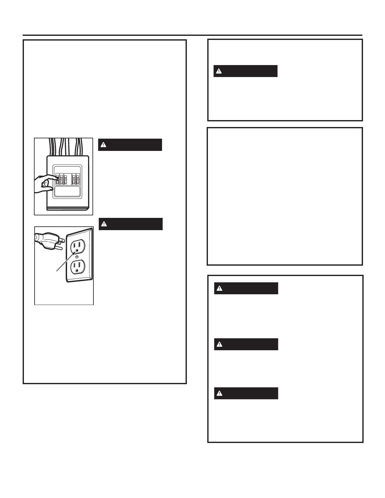
ADVERTENCIA
Riesgo de descarga
eléctrica. Puede provocar
una lesión o la muerte:
Quite el fusible o el
interruptor de circuitos
de la vivienda antes de
comenzar la instalación
para evitar una lesión por
descarga grave o fatal.
ADVERTENCIA
Riesgo de descarga
eléctrica. Puede provocar
una lesión o la muerte:
ESTE APARATO DEBE
CONTAR CON UNA
ADECUADA CONEXIÓN
A TIERRA para evitar una
descarga grave o fatal.
El cable eléctrico de este
aparato está equipado
con un enchufe de tres
patas (con conexión a tierra), lo cual requiere
que el mismo encaje con un tomacorriente para
tres patas (con conexión a tierra) de pared para
minimizar la posibilidad de descargas eléctricas.
Donde haya un tomacorriente de pared estándar
de dos espigas, resulta indispensable cambiarlo
por un tomacorriente de pared de tres espigas
con adecuada conexión a tierra, instalado por un
electricista calificado.
Asegúrese
GHTXHH[LVWH
una conexión
a tierra
apropiada
antes del uso
INSTRUCCIONES DE SEGURIDAD
IMPORTANTES
Riesgo de descarga
eléctrica. Puede provocar
una lesión o la muerte: Bajo NINGUNA
circunstancia corte, deforme o quite las clavijas
del cable de energía. No utilice un cable de
extensión. No cumplir con esta indicación
puede provocar un incendio.
ADVERTENCIA
REQUISITOS ELÉCTRICOS
/DFODVLILFDFLyQGHOSURGXFWRHVGHYDWLRV
&$$&KHUW]DPSHULRV\NLORYDWLRV
Este producto debe estar conectado a un circuito
GHVXPLQLVWURGHOYROWDMH\IUHFXHQFLDDSURSLDGRV
El tamaño del alambre debe conformarse a los
UHTXLVLWRVGHO1DWLRQDO(OHFWULF&RGHRDOFyGLJR
ORFDOHQHIHFWRSDUDHVWHtQGLFHGHNLORYDWLRV(O
FDEOHHOpFWULFRGHDOLPHQWDFLyQ\HOLQWHUUXSWRU
GHEHUiQOOHYDUVHDXQWRPDFRUULHQWH~QLFR
FRQHFWDGRDWLHUUDGHDDPSHULRV/D
caja del tomacorriente deberá estar localizada
HQHOJDELQHWHHQFLPDGHOKRUQR/DFDMD
del tomacorriente debe ser instalada por un
electricista calificado y debe conformarse al
National Electrical Code o al código local en
efecto.
PRECAUCIÓN
En pos de la seguridad
personal, la superficie de montaje debe ser
capaz de soportar la carga del gabinete, además
del peso adicional (de 63 a 85 libras) de este
producto, más las cargas adicionales del horno
de hasta 50 libras o un peso total entre 113 y
135 libras.
PRECAUCIÓN
En pos de la seguridad
personal, este producto no puede ser instalado
en sistemas de gabinetes tales como los
llamados “islas” o “penínsulas.” Éste debe ser
montado tanto a un gabinete superior como a
una pared.
PRECAUCIÓN
Para evitar el riesgo
de una lesión personal (en la espalda u otras
lesiones debido a peso excesivo del horno
microondas) o daños a la propiedad, hacen
falta dos personas para instalar este horno
microondas.
4
CAMPANA DE ESCAPE
/DVLJXLHQWHWDEODGHVFULEHXQHMHPSORGHXQDSRVLEOH
instalación de red de conductos.
NOTA: Lea las siguientes dos páginas solamente si planea ventilar el escape hacia el exterior. Si por el contrario
planea recircular el aire de vuelta hacia el salón, continúe en la página 11.
ESCAPE SUPERIOR EXTERNO (EJEMPLO SOLAMENTE)
NOTA3DUDHOHVFDSHSRVWHULRUVHGHEHWHQHUFXLGDGRDODOLQHDUHOHVFDSHHQWUHORVHVSDFLRVGHORVSRVWHVGHYLJDGHODSDUHG
RODSDUHGGHEHUtDVHUSUHSDUDGDHQHOPRPHQWRGHVXFRQVWUXFFLyQGHMDQGRVXILFLHQWHHVSDFLRHQWUHORVSRVWHVGHYLJDGHOD
pared para acomodar el escape.
LONGITUD NÚMERO LONGITUD
PARTES DEL CONDUCTO EQUIVALENTE x USADO =
7DSDGHOWHFKR SLHV [  SLHV
Conducto recto de 12 pies
SLHV [  SLHV
UHGRQGRGHƎ
Adaptador de transición
SLHV [  SLHV
de rectángulo a redondo*
/DORQJLWXGGHODVSDUWHVGHORVFRQGXFWRVHTXLYDOHQWHVHVWiEDVDGDHQSUXHEDVUHDOHV\UHIOHMDQ
ORVUHTXLVLWRVSDUDORJUDUXQDEXHQDYHQWLODFLyQFRQFXDOTXLHUFDPSDQDGHHVFDSH
Longitud total = 41 pies
* IMPORTANTE:6LVHXVDXQDGDSWDGRUGHWUDQVLFLyQGHUHFWiQJXORDUHGRQGRODVHVTXLQDVGHOIRQGR
GHOUHJXODGRUGHWLURVGHEHUiQFRUWDUVHSDUDTXHHQFDMHQXVDQGRODVWLMHUDVGHFRUWHSDUDSHUPLWLUHO
PRYLPLHQWROLEUHGHOUHJXODGRUGHWLURV
/DVLJXLHQWHWDEODGHVFULEHXQHMHPSORGHXQDSRVLEOH
instalación de red de conductos.
Instrucciones de instalación
ESCAPE POSTERIOR EXTERNO (EJEMPLO SOLAMENTE)
LONGITUD NÚMERO LONGITUD
PARTES DEL CONDUCTO EQUIVALENTE x USADO =
7DSDGHSDUHG SLHV [  SLHV
Conducto recto de 3 pies
SLHV [  SLHV
UHFWDQJXODUGH
1
»4Ǝ[Ǝ
&RGRGH SLHV [  SLHV
/DORQJLWXGGHODVSDUWHVGHORVFRQGXFWRVHTXLYDOHQWHVHVWiEDVDGDHQSUXHEDV
UHDOHV\UHIOHMDQORVUHTXLVLWRVSDUDORJUDUXQDEXHQDYHQWLODFLyQFRQFXDOTXLHU
campana de escape. Longitud total = 63 pies
5
/DORQJLWXGGHODVSDUWHVGHFRQGXFWRVHTXLYDOHQWHVHVWiEDVDGD
HQSUXHEDVUHDOHV\UHIOHMDQORVUHTXLVLWRVSDUDORJUDUXQDEXHQD
YHQWLODFLyQFRQFXDOTXLHUFDPSDQDGHHVFDSH
* IMPORTANTE: Si se usa un adaptador de
WUDQVLFLyQGHUHFWiQJXORDUHGRQGRODVHVTXLQDVGHO
fondo del regulador de tiros deberán ser cortadas
SDUDTXHHQFDMHQXVDQGRODVWLMHUDVGHFRUWHSDUD
SHUPLWLUHOPRYLPLHQWROLEUHGHOUHJXODGRUGHWLURV
Instrucciones de instalación
LONGITUD NÚMERO LONGITUD
PARTES DE CONDUCTO EQUIVALENTE x USADO = EQUIVALENTE
Adaptador de transición de
SLHV [  SLHV
rectángulo a redondo*
7DSDGHSDUHG SLHV [  SLHV
&RGRGH SLHV [  SLHV
&RGRGH SLHV [  SLHV
&RGRGH SLHV [  SLHV
&RGRGH SLHV [  SLHV
7DSDGHWHFKR SLHV [  SLHV
&RQGXFWRUHFWRGHƎUHGRQGR
SLHV [  SLHV
o rectangular de 3
1
»4Ǝ[Ǝ
Total red de conductos = pies
NOTA: Si usted necesita instalar conductos, tenga
SHQGLHQWHTXHODORQJLWXGWRWDOGHOFRQGXFWRUHFWDQJXODUGH
3
1
»4Ǝ[ƎRHOFRQGXFWRUHGRQGRGHƎGHGLiPHWURno debe
sobrepasar 140 pies equivalentes.
/DYHQWLODFLyQH[WHUQDUHTXLHUHXQ&21'8&72'(
&$03$1$'((6&$3(/HDORVLJXLHQWHFXLGDGRVDPHQWH
NOTA: (VLPSRUWDQWHTXHODYHQWLODFLyQVHDLQVWDODGD
usando la ruta más directa y con la menor cantidad de
FRGRVSRVLEOH(VWRDVHJXUDODYHQWLODFLyQGHOHVFDSH\
D\XGDDSUHYHQLUEORTXHRVTambién, cerciórese de que
el regulador de tiro pende libremente y nada bloquea
los conductos.
Conexiones de escape:
/DFDPSDQDGHHVFDSHKDVLGRGLVHxDGDSDUDHQFDMDU
con un conducto rectangular de 3
1
»4Ǝ[ƎHVWiQGDU
Si un conducto redondo es necesario, se debe usar un
adaptador de transición de rectangular a redondo.
No use un conducto menor de 6Ǝ de diámetro.
Longitud máxima del conducto:
3DUDORJUDUXQPRYLPLHQWRVDWLVIDFWRULRGHODLUHOD
longitud total del conducto rectangular de 3
1
»4Ǝ[Ǝ
RHOFRQGXFWRUHGRQGRGHƎGHGLiPHWURno debe
VREUHSDVDUSLHVHTXLYDOHQWHV
Los codos, transiciones, paredes y tapas
de techo, etc.,
presentan resistencia adicional al flujo
GHDLUH\VRQHTXLYDOHQWHVDXQDVHFFLyQGHFRQGXFWR
UHFWRHOFXDOHVPiVODUJRTXHVXWDPDxRItVLFRUHDO
Cuando calcule la longitud total del conducto, agregue
ODVORQJLWXGHVHTXLYDOHQWHVGHWRGDVODVWUDQVLFLRQHV
y adaptadores, más la longitud de todas las secciones
GHFRQGXFWRUHFWDV/DWDEODPiVDGHODQWHPXHVWUD
cómo puede calcular la longitud aproximada de la red
de conductos usando pies aproximados de longitudes
HTXLYDOHQWHVGHDOJXQRVFRQGXFWRVWtSLFRV
6
DA—OS – ENVÍO / INSTALACIÓN
Si la unidad se daña durante el envío,GHYXHOYD
ODXQLGDGDODOPDFpQGRQGHODDGTXLULySDUDVX
reparación o reemplazo.
Si el cliente daña la unidad, la reparación o el
reemplazo es responsabilidad del cliente.
Si el instalador daña la unidadVLQRHVHO
FOLHQWHODUHSDUDFLyQRUHHPSOD]RVHGHEHKDFHU
por medio de un arreglo entre el cliente y el
instalador.
Instrucciones de instalación
PARTE CANTIDAD
 7RUQLOORVGHPDGHUD

1
»4Ǝ[Ǝ
7RUQLOORVEDVFXODQWHV
\WXHUFDVGHPDULSRVD

1
»4Ǝ[Ǝ
7RUQLOORVGHPiTXLQD
autoalineables

1
»4Ǝ[
1
»4Ǝ
Arandela aislante de 1
QLOyQSDUDJDELQHWHV
PHWiOLFRV
PAQUETE DE ELEMENTOS
PARTES ADICIONALES
PARTE
CANTIDAD
Plantilla para
1
el gabinete
superior
Plantilla para
1
la pared
posterior
,QVWUXFFLRQHV
1
de instalación
Filtro de
2
grasa
empacados
por separado
PARTES INCLUIDAS
Usted encontrará los elementos de instalación en
XQSDTXHWHMXQWRFRQODXQLGDG,QVSHFFLRQHSDUD
FHUFLRUDUVHGHTXHWLHQHWRGDVODVSDUWHV
NOTA: Se incluyen algunas partes adicionales.
7
HERRAMIENTAS QUE NECESITARÁ
'HVWRUQLOODGRUHVGH
estrella #1 y #2
/iSL]
Regla recta y cinta
PpWULFD
Escuadra de
carpintero
RSFLRQDO
7LMHUDVSDUDFRUWDUODWyQ
SDUDFRUWDUHOUHJXODGRU
GHWLURVLHVQHFHVDULR
7DODGURHOpFWULFRFRQEURFDV
de
3
»16Ǝ
1
»2Ǝ\
5
»8Ǝ
XQPDUWLOORRSFLRQDO
'HWHFWRUGHSRVWHV
GHYLJDR
%ORTXHVGHUHOOHQRR
pedazos de madera,
si son necesarios para
rellenar el gabinete
XVDGRVVRODPHQWH
en la instalación de
JDELQHWHVDSR\DGRV
Guantes
6LHUUDGHVDEOHDJXMHURRGH
RMRGHFHUUDGXUD
1LYHO
Cinta de conductos o cinta
DGKHVLYDSURWHFWRUD
ESPACIO DE MONTAJE
NOTAS:
(OHVSDFLRHQWUHORVJDELQHWHVGHEHVHUGHƎ
de ancho y debe estar libre de obstrucciones.
Si el espacio entre los gabinetes es mayor de
ƎXQ³)LOOHU3DQHO.LW´SRGUtDVHUQHFHVDULR
para rellenar las brechas entre el horno y los
gabinetes. Su Manual del Propietario contiene
HOQ~PHURGHNLWSDUDVXPRGHOR
Este horno microondas es para ser instalado
SRUHQFLPDGHHVWXIDVKDVWDƎGHDQFKR
6LXVWHGVHGLVSRQHDYHQWLODUVXKRUQR
PLFURRQGDVKDFLDHOH[WHULRUYHUOD6HFFLyQGH
Campana de Escape para la preparación del
conducto de escape.
Cuando se instale el horno microondas
debajo de gabinetes de fondos lisos
y planos, tenga cuidado de seguir
cuidadosamente las instrucciones en
la plantilla del gabinete superior para el
espacio de tolerancia del cable eléctrico.
Modelos con ventilación superior: No
permite que los gabinetes u otros objetos
obstruyan
el flujo de aire del ventilador.
* Máx. de 13”: para una instalación estándar,
una profundidad del gabinete de 15”
requiere pasos adicionales utilizando el kit
de instalación adicional JX15BUMPWW/BB.
Protector posterior
de salpicaduras
ƎRPiV
desde el
piso hasta
la parte
superior
del horno
Ǝ
2Ǝ
Ǝ
mín.
16-
1
»2Ǝ
El extremo
del fondo del
gabinete necesita
HVWDUDƎR
más a partir de la
superficie de la
estufa
Instrucciones de instalación
7LMHUDVSDUDFRUWDUOD
SODQWLOODVLHVQHFHVDULR
Gafas de seguridad
Ǝ
máx*.
/DGLVWDQFLDPtQLPD
desde el costado
de la bisagra de
la puerta hasta la
pared adyacente
GHEHHTXLYDOHUDô´
8
CÓMO REMOVER EL HORNO
MICROONDAS DEL EMBALAJE /
CÓMO REMOVER EL PLATO
DE MONTAJE
5HPXHYDODVLQVWUXFFLRQHVGHLQVWDODFLyQORV
ILOWURVODEDQGHMDGHFULVWDO\ODEROVDSHTXHxD
GHOHTXLSR1RUHPXHYDHOSURWHFWRUIURQWDOGH
espuma de poliestireno del horno.
'REOHWRWDOPHQWHKDFLDDWUiVODVFXDWURWDSDV
de cartón hacia los lados opuestos de la
caja. Entonces descubra el horno y el cartón
en la parte superior. El horno debería estar
descansando sobre la espuma de poliestireno.
A
.
Caja
7LUHGHOFDUWyQKDFLDDUULED\OHMRVGHOKRUQR
5HPXHYDORVWRUQLOORVIURQWDOHVGHODVSODFDVGH
la montura. Estas placas serán utilizadas como
la plantilla trasera en la pared y para montar.
Puede desechar estos tornillos.
Plato de
montaje
7RUQLOORV
Poliestireno
2
3
5
5HPXHYD\GHVHFKHGHELGDPHQWHODVEROVDVGH
plástico.
4
1
Encuentre los postes, usando uno de los
PpWRGRVVLJXLHQWHV
A8VHXQGHWHFWRUGHSRVWHV±XQGLVSRVLWLYR
PDJQpWLFRTXHORFDOL]DFODYRV
O
B. Use un martillo para golpear ligeramente a
WUDYpVGHODVXSHUILFLHGHPRQWDMHKDVWD
HQFRQWUDUXQVRQLGRVyOLGR(VWRLQGLFDUiTXH
KD\XQSRVWHGHYLJDHQHVHOXJDU
'HVSXpVGHORFDOL]DUHOSRVWHRORVSRVWHVGHYLJD
encuentre el centro mediante el análisis de la
SDUHGXVDQGRXQFODYRSHTXHxRSDUDGDUVH
FXHQWDGHGyQGHHVWiQORVERUGHVGHOSRVWH/XHJR
FRORTXHXQDPDUFDHQHOFHQWURGHORVERUGHV
(OFHQWURGHFXDOTXLHUSRVWHDG\DFHQWHGHEHUiVHU
HQWUHƎyƎGHVGHHVWDPDUFD
7UDFHXQDOtQHDKDFLDDEDMRLQGLFDQGRHOFHQWUR
del poste.
EL HORNO MICROONDAS DEBE CONECTARSE
POR LO MENOS A UN POSTE DE LA PARED.
1
CÓMO ENCONTRAR LOS POSTES
DE VIGA EN LA PARED
B
.
2
CÓMO COLOCAR EL PLATO DE MONTAJE
1
3RVWHVGHYLJD
en la pared
Centro
3
Instrucciones de instalación
9
CÓMO DETERMINAR LA LOCALIZACIÓN DEL PLATO DE MONTAJE
DEBAJO DE SU GABINETE
C.
Sus gabinetes podrían tener marcos de decoración
TXHLQWHUILHUDQFRQODLQVWDODFLyQGHOKRUQR
PLFURRQGDV5HPXHYDORVPDUFRVGHFRUDWLYRVSDUD
LQVWDODUHOKRUQRDSURSLDGDPHQWH\SDUDKDFHUTXH
TXHGHQLYHODGR
EL HORNO MICROONDAS DEBE QUEDAR
NIVELADO.
8VHXQQLYHOSDUDFHUFLRUDUVHGHTXHHOIRQGRGHO
JDELQHWHHVWiQLYHODGR
Si los gabinetes tienen un saliente frontal solamente,
sin marco posterior o lateral, instale el plato de
montaje a la misma distancia de la profundidad
del saliente. Este mantendrá el horno microondas
QLYHODGR
Mida la profundidad interna del frente del saliente.
7UDFHXQDOtQHDKRUL]RQWDOHQODSDUHGSRVWHULRUD
una distancia debajo del fondo del gabinete igual
a la profundidad interna del frente saliente.
Para este tipo de instalación con saliente frontal
solamente, alinee las orejillas de montaje con la
línea horizontal, sin tocar el fondo del gabinete
FRPRVHGHVFULELyHQHO3DVR'
Posición del plato – debajo de gabinetes
de fondo plano
Posición del plato – debajo de gabinetes
de fondo apoyado con frente saliente
/DVRUHMLOODVGHOSODWRGH
montaje tocan el fondo
del gabinete
Plato de montaje
con orejillas por
debajo del fondo
del gabinete
a la misma
GLVWDQFLDTXHOD
profundidad
del saliente
3RUORPHQRVƎKDVWDƎ
Posición del plato – debajo de gabinetes
de fondo apoyado en un marco
/DVRUHMLOODVGHO
plato de montaje
tocan el marco
posterior
Instrucciones de instalación
ƎKDVWDODHVWXID
ƎKDVWDODHVWXID
1
2
3
10
CÓMO ALINEAR EL PLATO DE MONTAJE SOBRE LA PARED
Use guantes de protección
para evitar cortaduras en sus
dedos con los extremos filosos.
7UDFHXQDOtQHDYHUWLFDOHQODSDUHGHQHOFHQWURGHO
HVSDFLRGHƎGHDQFKR
Use el plato de montaje como la plantilla para
ODSDUHGSRVWHULRU&RORTXHHOSODWRGHPRQWDMH
HQODSDUHGFHUFLRUiQGRVHGHTXHODVRUHMLOODVVH
encuentran tocando el fondo del gabinete o la línea
horizontal trazada en el Paso C para gabinetes
con saliente frontal. Alinee la muesca y línea del
centro en el fondo del plato de montaje con la
línea de centro en la pared.
Mientras sostiene el plato de montaje con una mano,
WUDFHFtUFXORVHQODSDUHGHQORVDJXMHURV$%&\'
YHUODLOXVWUDFLyQDQWHULRUODSODFDUHDOHVWiPDUFDGD
FRQIOHFKDV Deben usarse cuatro agujeros para
el montaje.
NOTA:/RVDJXMHURV&\'YDQHQHOLQWHULRUGHO
iUHD(6LQLHO&QLHO'HVWiQHQXQSRVWHGHYLJD
encuentre un poste en algún otro lugar en el área
(\PDUTXHXQTXLQWRFtUFXORSDUDDOLQHDUVHFRQHO
poste. Es importante usar por lo menos un tornillo
de madera montado firmemente en un poste para
apoyar el peso del horno.
Aparte el plato de montaje.
ADVERTENCIA
Riesgo de descarga eléctrica.
Puede provocar lesiones o la muerte. Tenga cuidado
de no perforar el cableado eléctrico ubicado dentro
de las paredes o gabinetes.
Perfore agujeros en los círculos. Si hay un poste de
YLJDSHUIRUHXQDJXMHURGH
3
»16s para los tornillos de
PDGHUD3DUDORVDJXMHURVTXHQRTXHGDURQDOLQHDGRV
FRQHOSRVWHGHYLJDSHUIRUHXQDJXMHURGH
5
»8s para
los tornillos basculantes. Perfore dos agujeros de
5
»8s
para los tornillos con resortes.
NOTA: TODAVÍA NO MONTE EL PLATO.
2
3
4
7UDFHXQD
OtQHDYHUWLFDO
en la pared a
partir del centro
del gabinete
superior
Area E
Agujero A
Agujero B
$JXMHUR'
D.
Instrucciones de instalación
1
Muescas
de la línea
del centro
Agujero C
PRECAUCIÓN
11
A
TIPOS DE INSTALACIÓN
(Escoja A, B o C)
Este horno microondas está diseñado para adaptarse a
ORVVLJXLHQWHVWUHVWLSRVGHYHQWLODFLyQ
A. Escape superior exterior (Conducto vertical)
B. Escape posterior exterior (Conducto horizontal)
C. Recirculación (Sin conducto de ventilación)
127$(VWHKRUQRPLFURRQGDVHVHQYLDGR\DHQVDPEODGR
SDUDXQHVFDSHVXSHULRUH[WHULRUH[FHSWRSDUDPRGHORV
HQYuDGRVFRQHVFDSHGHUHFLUFXODFLzQ6HOHFFLRQHHOWLSR
GHYHQWLODFLyQUHTXHULGRSDUDVXLQVWDODFLyQ\SURFHGD
a tal sección.
ESCAPE SUPERIOR EXTERIOR
(CONDUCTO VERTICAL)
ESCAPE POSTERIOR EXTERIOR
(CONDUCTO HORIZONTAL)
RECIRCULACIÓN (SIN CONDUCTO
DE VENTILACIÓN)
Ver página 12
Ver página 16
Ver página 20
8Q.LWGHDFFHVRULRVGHILOWURGHFDUERQLOODHV
QHFHVDULRSDUDHOVLVWHPDVLQYHQWLODFLyQ&RQVXOWH
su Manual del Propietario para obtener el número del
NLW
El adaptador está
en su lugar para
el escape superior
exterior
Instrucciones de instalación
2
B
C
12
&RORTXHHOSODWRGHPRQWDMHFRQWUDODSDUHGH
inserte las alas de mariposa en los agujeros de la
pared para montar el plato.
NOTA: Antes de apretar los tornillos basculantes y
ORVWRUQLOORVGHPDGHUDFHUFLyUHVHGHTXHODVRUHMLOODV
HQHOSODWRGHPRQWDMHWRTXHQHOIRQGRGHOJDELQHWH
FXDQGRVRQHPSXMDGDVFRQWUDODSDUHG\GHTXH
HOSODWRHVWpFHQWUDGRDSURSLDGDPHQWHGHEDMRGHO
gabinete.
PRECAUCIÓN
Tenga cuidado de evitar
pellizcar sus dedos entre la parte posterior del
plato de montaje y la pared.
$SULHWHWRGRVORVWRUQLOORV7LUHGHOSODWRHQ
dirección opuesta a la pared para ayudar a
apretar los tornillos.
3
A
4
ESCAPE SUPERIOR EXTERIOR (Conducto vertical)
PERSPECTIVA GENERAL
DE LA INSTALACIÓN
A1. Cómo adherir el plato de
montaje a la pared
A2. Prepare el gabinete superior
A3. Controle la Orientación del
Motor del Calefactor
A4. Adapte el Calefactor para la
Ventilación Externa
A5.,QVSHFFLRQHODRSHUDFLyQ
del regulador de tiro
A6. Monte el horno
microondas
A7. Ajuste el adaptador
de escape
A8. Conecte el conducto
Pared
Plato de
montaje
Espaciadores para los
basculantes mayores
TXHHODQFKRGHODSDUHG
Extremo del tornillo
7RUQLOORGH
mariposa
Alas de mariposa
Para usar los tornillos basculantes:
Instrucciones de instalación
CÓMO ADHERIR LA PLACA
DE MONTAJE A LA PARED
A1
Pegue el plato a la pared usando los tornillos
basculantes. Por lo menos un tornillo de madera
debe ser usado para pegar el plato al poste de la
SDUHG/DVXELFDFLRQHVUHFRPHQGDGDVVREUHOD
SODFDGHPRQWDMHVHLQGLFDQHQ$%&\'
5HPXHYDODVPDULSRVDVGHOEDVFXODQWHGHORV
tornillos.
,QVHUWHORVWRUQLOORVHQHOSODWRGHPRQWDMHDWUDYpV
de los agujeros diseñados para ser insertados en
ODSDUHGGHPDPSRVWHUtDVHFD\SHJXHRWUDYH]
las mariposas de
3
»4ƎHQFDGDWRUQLOOR
1
2
A
B
C
'
13
USE LA PLANTILLA DEL
GABINETE SUPERIOR PARA LA
PREPARACIÓN DEL GABINETE
'HEHUiSHUIRUDUDJXMHURVSDUDORVWRUQLOORVGHDSR\R
superiores, un agujero suficientemente grande
SDUDTXHHOFDEOHHOpFWULFRTXHSD\XQUHFRUWHOR
suficientemente grande como para
TXHHODGDSWDGRUGHHVFDSHSXHGDVHULQWURGXFLGR
A2.
 /HDODVLQVWUXFFLRQHVVREUHOD3/$17,//$'(/
*$%,1(7(683(5,25
 3pJXHORGHEDMRGHOJDELQHWHVXSHULRU
 7DODGUHORVDJXMHURVVLJXLHQGRODVLQVWUXFFLRQHV
HQOD3/$17,//$'(/*$%,1(7(683(5,25
PRECAUCIÓN
Use gafas de seguridad
cuando perfore los agujeros en el fondo del
gabinete.
Instrucciones de instalación
CONTROLE LA ORIENTACIÓN DEL
MOTOR DEL CALEFACTOR
/DDEHUWXUDGHODVSDOHWDVGHOYHQWLODGRUGHO
calefactor debe apuntar hacia la parte superior del
KRUQRPLFURRQGDV6LODDEHUWXUDGHOYHQWLODGRU\D
está apuntada hacia la parte superior del horno
PLFURRQGDVYD\DGLUHFWRDO3DVR$'HRWURPRGR
continúe con el Paso A4 para ajustar la orientación
del motor.
ADAPTACIÓN DEL CALEFACTOR
PARA LA VENTILACIÓN EXTERNA
5HWLUH\JXDUGHORVWRUQLOORVTXHVRVWLHQHQHO
motor del calefactor al horno microondas.
Retire y guarde el escudo metálico del calefactor
en la parte superior del microondas, deslizando el
mismo de forma recta.
A3.
A4.
1
2
Parte posterior del
horno microondas
7RUQLOORVGH
Retención del
Calentador
Plato del calefactor
7RUQLOORGH5HWHQFLyQGHO
Calentador
ADAPTACIÓN DEL CALEFACTOR
PARA LA VENTILACIÓN EXTERNA
(Cont.)
Adhiera el escudo metálico del calefactor sobre
la parte trasera del microondas, deslizando el
mismo hacia abajo.
$EUDODSXHUWDGHOFDOHIDFWRUOHYDQWDQGRHOPLVPR
sobre la parte trasera del horno microondas.
Con cuidado, empuje hacia usted la unidad del
FDOHIDFWRU/RVFDEOHVVHH[WHQGHUiQORVXILFLHQWH
como para permitirle ajustar la unidad del
calefactor.
Haga rodar la unidad del calentador 90º, de modo
TXHODVDEHUWXUDVGHODVSDOHWDVGHOYHQWLODGRU
enfrenten la parte superior del horno.
A4.
3
4
5
6
ANTES: Aberturas
de las Paletas del
Ventilador Hacia
Arriba
DESPUÉS: Aberturas
de las Paletas del
Ventilador Hacia
Arriba
Escudo del
Calefactor
Roll
NOTA: Asegúrese
GHTXHORVFDEOHV
permanezcan
dirigidos hacia las
ranuras de la
estructura del
motor.
14
INSPECCIONE LA OPERACIÓN
DEL REGULADOR DE TIRO
A5.
Adaptador de escape
Plato del
calefactor
Regulador
de tiro
Parte posterior del
horno microondas
 &RORTXHHOKRUQRPLFURRQGDVHQVXSRVLFLyQ
YHUWLFDOFRQODSDUWHVXSHULRUKDFLDDUULED
Cerciórese de que remueva la cinta y el
regulador de tiro gira fácilmente antes de
montar el horno microondas.
 'HVOLFHHOUHJXODGRUGHWLURHQVXOXJDU
$VHJ~UHVHGHTXHTXHGHELHQVXMHWRDORVJDQFKRV
de retención.
 'HEHUiKDFHUDMXVWHVSDUDDVHJXUDUVHGHTXH
existe alineación apropiada con el sistema de
FRQGXFWRVGHVXFDVDGHVSXpVGHODLQVWDODFLyQGHO
horno microondas.
3
2
Gire el frente del horno
contra el fondo del gabinete.
1
CÓMO MONTAR EL HORNO
MICROONDAS
A5.
PRECAUCIÓN
PARA OBTENER UNA
INSTALACIÓN MÁS FÁCIL Y EN POS DE LA
SEGURIDAD PERSONAL, SE RECOMIENDA
QUE DOS PERSONAS INSTALEN ESTE HORNO
MICROONDAS.
IMPORTANTE: No agarre ni use
la manija de la puerta durante la
instalación.
NOTA: Si su gabinete es de metal, use la arandela
GHQLOyQDOUHGHGRUGHOFDEOHHOpFWULFRSDUDHYLWDU
TXHHOPLVPRVHDFRUWDGR
NOTA:5HFRPHQGDPRVHOXVRGHEORTXHVGH
relleno si el frente del gabinete cuelga por debajo
del estante del fondo del gabinete.
IMPORTANTE: Si no se usan bloques
de relleno, podrían ocurrir daños por
apretar demasiado los tornillos.
,QVHUWHXQWRUQLOORGHDXWRDOLQHDFLyQDWUDYpVGHO
agujero central superior del gabinete. Asegure el horno
temporalmente girando el tornillo por lo menos
dos vueltas completasGHVSXpVGHTXHODVURVFDV
KD\DQDJDUUDGR/XHJRTXHGDUiQWRWDOPHQWH
DSUHWDGDVCerciórese de mantener el cable eléctrico
estirado.
Tenga cuidado de no pellizcar el cable,
especialmente cuando se monte al nivel del fondo
del gabinete.
NOTA: Cuando se encuentre
montando el horno microondas,
HQURVTXHHOFDEOHHOpFWULFRD
WUDYpVGHODJXMHURHQHOIRQGRGHO
JDELQHWHVXSHULRU0DQWpQJDOR
WHQVRDWUDYpVGHORV3DVRVGHO
1RSHOOL]TXHHOFDEOHQLWLUH
del horno por el cable.
/HYDQWHHOKRUQR
microondas, inclínelo
hacia adelante, y
enganche las ranuras
en el extremo inferior
posterior en cuatro
orejillas inferiores del
plato de montaje.
Ganchos de retención
Instrucciones de instalación
ADAPTACIÓN DEL
CALEFACTOR PARA LA
VENTILACIÓN EXTERNA (Cont.)
9XHOYDDFRORFDUODXQLGDGGHOFDOHIDFWRUHQOD
abertura.
PRECAUCIÓN
No empuje ni extienda
el cableado de la unidad del calefactor.
Asegúrese de que los cables no posean
cortes.
Cierre la puerta del calefactor. Asegure el
calefactor al microondas usando los tornillos del
Paso 1.
A4.
7
8
15
Parte posterior
del horno
microondas
Para ajustes de lado a
lado, deslice el adaptador
del tubo de escape según
sea necesario.
Regulador de tiro
4
Pegue el horno microondas a la parte superior del
gabinete.
7
Frente del gabinete
Estante del fondo del gabinete
Apriete los tres tornillos exteriores hacia la parte
GHDUULEDGHOKRUQRPLFURRQGDV0LHQWUDVDSULHWDORV
tornillos, mantenga el horno microondas en su lugar
FRQWUDODSDUHG\HOJDELQHWHVXSHULRU
,QVWDOHHOILOWURGHJUDVD&RQVXOWHHO0DQXDOGHO
3URSLHWDULRHQHOVLWLRZHE*($SSOLDQFHVFRP
%ORTXHGHUHOOHQR
Parte superior del horno microondas
(TXLYDOHQWHD
la profundidad
del retroceso
del gabinete
,QVHUWHWRUQLOORVDXWRDOLQHDEOHVDWUDYpVGHORV
agujeros exteriores superiores del horno. Gire dos
YXHOWDVFRPSOHWDVHQFDGDWRUQLOOR
6
Instrucciones de instalación
CÓMO AJUSTAR EL
ADAPTADOR DE ESCAPE
A7.
Abra el gabinete superior y ajuste el adaptador
de escape para conectarlo al conducto de la casa.
CÓMO CONECTAR
EL CONDUCTO
1
2
Extienda el conducto de la casa hacia abajo
para conectarlo con el adaptador de escape.
Selle las juntas del conducto de escape usando
FLQWDDGKHVLYDGHFRQGXFWRV
A8.
Conducto de la casa
7RUQLOORDXWRDOLQHDEOH
5
CÓMO MONTAR EL HORNO
MICROONDAS
(continuación)
A6.
T
u
r
n
t
o
S
e
l
e
c
t
P
r
e
s
s
t
o
E
n
t
e
r
Reheat
Timer
On/Off
Defrost
Weight/Time
Start
Pause
Cancel
Off
Lock Controls
Hold 3 Sec
Cook
Time
Set
Clock
Options Help
Surface
Light
Vent Fan
Popcorn
B
everage
Microwave
Express
Warm
Power
Level
Auto
Cook
Combination
Fast Bake
Convection
Roast
Turntable
Convection
Bake
16
ESCAPE POSTERIOR EXTERNO (Conducto horizontal)
PERSPECTIVA
GENERAL DE LA
INSTALACIÓN
B1. Prepare la pared posterior
B2. Cómo adherir el plato
de montaje a la pared
B3. Prepare el gabinete superior
B4. Ajuste el calefactor
B5. Monte el horno microondas
Instrucciones de instalación
B
CÓMO PREPARAR LA PARED
POSTERIOR PARA EL ESCAPE
POSTERIOR
B1.
Necesita cortar una abertura en la pared posterior
para el escape exterior.
 /HDODVLQVWUXFFLRQHVHQOD3/$17,//$3$5$/$
3$5('3267(5,25
 3pJXHODFRQFLQWDDGKHVLYDDODSDUHGSRVWHULRU
DOLQHiQGRODFRQORVDJXMHURVSUHYLDPHQWH
perforados para los agujeros A y B en el plato de la
pared.
• Corte la apertura, siguiendo las instrucciones de
OD3/$17,//$3$5$/$3$5('3267(5,25
CÓMO ADHERIR LA PLACA
DE MONTAJE A LA PARED
B2
Pegue el plato a la pared usando los tornillos
basculantes. Por lo menos un tornillo de madera
debe ser usado para pegar el plato al poste de la
SDUHG/DVXELFDFLRQHVUHFRPHQGDGDVVREUHOD
SODFDGHPRQWDMHVHLQGLFDQHQ$%&\'
5HPXHYDODVPDULSRVDVGHOEDVFXODQWHGHORV
tornillos.
,QVHUWHORVWRUQLOORVHQHOSODWRGHPRQWDMHDWUDYpV
de los agujeros diseñados para ser insertados en
ODSDUHGGHPDPSRVWHUtDVHFD\SHJXHRWUDYH]
las mariposas de
3
»4ƎHQFDGDWRUQLOOR
1
2
A
B
C
'
17
USE LA PLANTILLA DEL
GABINETE SUPERIOR PARA
PREPARAR EL GABINETE
SUPERIOR
B3.
 /HDODVLQVWUXFFLRQHVVREUHOD3/$17,//$'(/
*$%,1(7(683(5,25
 3pJXHODGHEDMRGHOJDELQHWHVXSHULRU
 7DODGUHORVDJXMHURVVLJXLHQGRODVLQVWUXFFLRQHV
HQOD3/$17,//$'(/*$%,1(7(683(5,25
PRECAUCIÓN
Use gafas de seguridad
cuando perfore los agujeros en el fondo del
gabinete.
Pared
Plato de
montaje
Espaciadores para los basculantes
PD\RUHVTXHHODQFKRGHODSDUHG
7RUQLOORGH
mariposa
Alas de mariposa
Para usar los tornillos basculantes:
Extremo del tornillo
Instrucciones de instalación
Necesita perforar agujeros para los tornillos de
apoyo superiores y un agujero suficientemente
JUDQGHSDUDTXHHOFDEOHHOpFWULFRTXHSD
&RORTXHHOSODWRGHPRQWDMHFRQWUDODSDUHGH
inserte las alas de mariposa en los agujeros de
la pared para montar el plato.
NOTA: Antes de apretar los tornillos basculantes y
HOWRUQLOORGHPDGHUDFHUFLyUHVHGHTXHODVRUHMLOODV
HQHOSODWRGHPRQWDMHWRTXHQHOIRQGRGHOJDELQHWH
FXDQGRVHHPSXMHQFRQWUDODSDUHG\GHTXHHO
SODWRHVWpFHQWUDGRDSURSLDGDPHQWHGHEDMRGHO
gabinete.
PRECAUCIÓN
Tenga cuidado de evitar
pellizcar sus dedos entre la parte posterior del
plato de montaje y la pared.
$SULHWHWRGRVORVWRUQLOORV7LUHGHOSODWRHQGLUHFFLyQ
opuesta a la pared para ayudar a apretar los tornillos.
3
4
ANTES: Las aberturas
de la paleta del ventilador
están orientadas hacia
arriba
3
CÓMO ADAPTAR EL CALEFACTOR
DEL MICROONDAS PARA EL
ESCAPE POSTERIOR EXTERIOR
B4.
Extremo B
Extremo A
&XLGDGRVDPHQWHWLUHGHOFDOHIDFWRU/RVDODPEUHV
se extenderán lo suficiente como para permitirle
TXHXVWHGDMXVWHODXQLGDGGHOFDOHIDFWRU
1
5HPXHYD\JXDUGHHOWRUQLOORVTXHVRVWLHQHHO
motor del calefactor adherido al microondas.
Parte trasera del
horno microondas
7RUQLOORVGH
retención
2
$EUDODSXHUWDGHOFDOHIDFWRUOHYDQWDQGR
el mismo sobre la parte trasera del horno
microondas. Retire y guarde el escudo
metálico del calefactor en la parte trasera del
microondas, deslizando el mismo hacia arriba.
5HWLUH\JXDUGHODWDSDGHOYHQWLODGRUPHWiOLFR
en la parte trasera del microondas, deslizando la
misma hacia arriba.
4
Rote la unidad 180° en sentido contrario a las
agujas del reloj.
Antes de la rotación 'HVSXpVGHODURWDFLyQ
Parte posterior del
horno microondas
Parte posterior
del horno
microondas
18
Ruede la unidad del calefactor 90° de forma
WDOTXHODVDEHUWXUDVGHODSDOHWDGHOYHQWLODGRU
HVWpQRULHQWDGDVKDFLDODSDUWHSRVWHULRUGHO
horno microondas.
6
DESPUES: Las aberturas de la paleta del ventilador
están orientadas hacia atrás
&RORTXHODXQLGDGGHOFDOHIDFWRUGHQXHYRHQ
ODDEHUWXUD/DVDEHUWXUDVGHOHVFDSHGHO
calefactor deberán encajar con las aberturas
del escape en la parte posterior del horno
microondas.
PRECAUCIÓN
No tire ni estire los
cables del calefactor. Cerciórese de que los
alambres no están pellizcados.
8
9
&LHUUHODSXHUWDGHOYHQWLODGRU'HVOLFHHOHVFXGR
del calefactor sobre la parte superior de la
abertura de la puerta del calefactor. Asegúrese
GHTXHHQHOFDOHIDFWRUGHOKRUQRPLFURRQGDVVH
utilicen los tornillos de retención del calefactor
desde el Paso 1, excepto el tornillo de retención
del motor del calefactor superior.
Antes de la rotación 'HVSXpVGHODURWDFLyQ
Extremo A
Extremo B
Parte posterior del
horno microondas
Parte
posterior
del horno
microondas
5
CÓMO ADAPTAR EL CALEFACTOR
DEL MICROONDAS PARA EL
ESCAPE POSTERIOR EXTERIOR
(continuación)
B4.
6XDYHPHQWHUHPXHYDORVDODPEUHVGHODV
UDQXUDV5HGLULMDORVDODPEUHVDWUDYpVGH
las ranuras en el otro lado de la unidad del
calefactor.
Antes de redirigirlos 'HVSXpVGHUHGLULJLUORV
$ODPEUHVGLULJLGRVDWUDYpV
del lado derecho
$ODPEUHVGLULJLGRVDWUDYpV
GHOODGRL]TXLHUGR
Instrucciones de instalación
10
'HVOLFHHODGDSWDGRUGHHVFDSHGHQWURGHOD
parte trasera del microondas fijándolo dentro de
ODVOHQJHWDVGHEORTXHRLQIHULRUHV9HULILTXH
TXHODELVDJUDGHOUHJXODGRUGHWLURVHHQFXHQWUH
LQVWDODGDGHPRGRTXHTXHGHHQODSDUWH
VXSHULRU\TXHHOUHJXODGRUGHWLURVHPXHYD
OLEUHPHQWH9XHOYDDLQVWDODUHOWRUQLOORVXSHULRU
GHOPRWRUGHOYHQWLODGRUDWUDYpVGHODGDSWDGRU
ODSXHUWDGHOYHQWLODGRU\GHQWURGHODSDUWH
trasera del microondas.
Guía
Guía
Adaptador
Parte posterior del
horno microondas
Parte trasera del
horno microondas
7RUQLOORGH
retención
GHOYHQWLODGRU
Ventilador
7RUQLOORGHUHWHQFLyQ
de la puerta del
PRWRUGHOYHQWLODGRU
/HQJHWDV
GHEORTXHR
QR
PRVWUDGR
8ELTXHODVGRVSODFDV³VHSDUDGRUDV´HQHO
panel trasero del horno, cerca de la parte
superior del horno. Usando tijeras para
hojalata, con cuidado corte el área de la red
GHVGHORVGRVDJXMHURVMXQWRVTXHDVHJXUDQ
ODVVHSDUDFLRQHVFRQHOKRUQR&RUWHODV
cuatro redes en ambos separadores traseros;
HVWRSHUPLWLUiTXHHOIOXMRGHDLUHGHOYHQWLODGRU
salga hacia fuera desde la parte trasera del
horno.
PRECAUCIÓN
Asegúrese de recortar
los extremos puntiagudos desde las aberturas,
luego de retirar las placas de separación.
7
Escudo del
Calefactor
19
3
2
Gire el frente del horno contra el fondo del gabinete.
1
CÓMO MONTAR EL HORNO
MICROONDAS
PRECAUCIÓN
PARA OBTENER UNA
INSTALACIÓN MÁS FÁCIL Y EN POS DE LA
SEGURIDAD PERSONAL, SE RECOMIENDA
QUE DOS PERSONAS INSTALEN ESTE HORNO
MICROONDAS.
IMPORTANTE: No agarre ni use
la manija de la puerta durante la
instalación.
NOTA: Si su gabinete es de metal, use la arandela
GHQLOyQDOUHGHGRUGHOFDEOHHOpFWULFRSDUDHYLWDU
TXHHOPLVPRVHDFRUWDGR
NOTA: 5HFRPHQGDPRVHOXVRGHEORTXHVGH
relleno si el frente del gabinete cuelga por debajo
del estante del fondo del gabinete.
IMPORTANTE: Si no se usan bloques
de relleno, podrían ocurrir daños por
apretar demasiado los tornillos.
,QVHUWHXQWRUQLOORGHDXWRDOLQHDFLyQDWUDYpVGHO
agujero central superior del gabinete. Asegure
el horno temporalmente girando el tornillo por lo
menos dos vueltas completasGHVSXpVGHTXHODV
URVFDVKD\DQDJDUUDGR/XHJRTXHGDUiQWRWDOPHQWH
DSUHWDGDVCerciórese de mantener el cable eléctrico
estirado. Tenga cuidado de no pellizcar el cable,
especialmente cuando se monte al nivel del fondo
del gabinete.
/HYDQWHHOKRUQRPLFURRQGDVLQFOtQHORKDFLDDGHODQWH\
enganche las ranuras en el extremo inferior posterior en
cuatro orejillas inferiores del plato de montaje.
NOTA: Cuando se encuentre montando el horno
PLFURRQGDVHQURVTXHHOFDEOHHOpFWULFRDWUDYpVGHO
DJXMHURHQHOIRQGRGHOJDELQHWHVXSHULRU0DQWpQJDOR
WHQVRDWUDYpVGHORV3DVRVGHO1RSHOOL]TXHHO
cable ni tire del horno por el cable.
B5.
4
Pegue el horno microondas a la parte superior
del gabinete.
7
Frente del gabinete
Estante del fondo del gabinete
Apriete los tres tornillos exteriores hacia la parte
GHDUULEDGHOKRUQRPLFURRQGDV0LHQWUDVDSULHWDORV
tornillos, mantenga el horno microondas en su lugar
FRQWUDODSDUHG\HOJDELQHWHVXSHULRU
%ORTXHGHUHOOHQR
Parte superior del horno microondas
(TXLYDOHQWHD
la profundidad
del retroceso del
gabinete
,QVHUWHWRUQLOORVDXWRDOLQHDEOHVDWUDYpVGHORV
agujeros exteriores superiores del horno. Gire dos
YXHOWDVFRPSOHWDVHQFDGDWRUQLOOR
6
,QVWDOHHOILOWURGHJUDVD9HUHO0DQXDOGHO
3URSLHWDULRTXHYLHQHFRQHOKRUQRPLFURRQGDV
7RUQLOORDXWRDOLQHDEOH
5
Instrucciones de instalación
Cable de
Corriente
Self-Aligning Screws
T
u
r
n
t
o
S
e
l
e
c
t
P
r
e
s
s
t
o
E
n
t
e
r
Reheat
Timer
On/Off
Defrost
Weight/Time
Start
Pause
Cancel
Off
Lock Controls
Hold 3 Sec
Cook
Time
Set
Clock
Options Help
Surface
Light
Vent Fan
Popcorn
B
everage
Microwave
Express
Warm
Power
Level
Auto
Cook
Combination
Fast Bake
Convection
Roast
Turntable
Convection
Bake
20
Instrucciones de instalación
USE LA PLANTILLA DE
GABINETE SUPERIOR PARA LA
PREPARACIÓN DEL GABINETE
C2.
RECIRCULACIÓN (Sin conducto de ventilación)
PERSPECTIVA GENERAL DE LA
INSTALACIÓN
C1. Cómo adherir el plato de montaje
a la pared
C2. Prepare el gabinete superior
C3. Controle la Orientación del Motor del
Calefactor
C4. Adapte el Calefactor para la
Recirculación
C5. Monte el horno microondas
C6,QVWDOHHOILOWURGHFDUERQLOOD
 /HDODVLQVWUXFFLRQHVVREUHOD3/$17,//$'(/
*$%,1(7(683(5,25
 3pJXHODGHEDMRGHOJDELQHWHVXSHULRU
 7DODGUHXQDJXMHURVLJXLHQGRODVLQVWUXFFLRQHV
HQOD3/$17,//$'(/*$%,1(7(683(5,25
PRECAUCIÓN
Use gafas de seguridad
cuando perfore los agujeros en el fondo del
gabinete.
'HEHUiSHUIRUDUDJXMHURVSDUDORVWRUQLOORVGHDSR\R
superiores y un agujero suficientemente grande para
TXHHOFDEOHHOpFWULFRTXHSD
C
&RORTXHHOSODWRGHPRQWDMHFRQWUDODSDUHG
e inserte las alas de mariposa en los agujeros
de la pared para montar el plato.
NOTA: Antes de apretar los tornillos basculantes
\ORVWRUQLOORVGHPDGHUDFHUFLyUHVHGHTXHODV
RUHMLOODVHQHOSODWRGHPRQWDMHWRTXHQHOIRQGRGHO
gabinete cuando son empujadas contra la pared y de
TXHHOSODWRHVWpFHQWUDGRDSURSLDGDPHQWHGHEDMRGHO
gabinete.
PRECAUCIÓN
Tenga cuidado de evitar
pellizcar sus dedos entre la parte posterior del
plato de montaje y la pared.
$SULHWHWRGRVORVWRUQLOORV7LUHGHOSODWRHQGLUHFFLyQ
opuesta a la pared para ayudar a apretar los
tornillos.
3
4
Pared
Plato de
montaje
Espaciadores para los basculantes
PD\RUHVTXHHODQFKRGHODSDUHG
Extremo del tornillo
7RUQLOORGH
mariposa
Alas de mariposa
Para usar los tornillos basculantes:
CÓMO ADHERIR LA PLACA
DE MONTAJE A LA PARED
C1
Pegue el plato a la pared usando los tornillos
basculantes. Por lo menos un tornillo de madera
debe ser usado para pegar el plato al poste de la
SDUHG/DVXELFDFLRQHVUHFRPHQGDGDVVREUHOD
SODFDGHPRQWDMHVHLQGLFDQHQ$%&\'
5HPXHYDODVPDULSRVDVGHOEDVFXODQWHGHORV
tornillos.
,QVHUWHORVWRUQLOORVHQHOSODWRGHPRQWDMHDWUDYpV
de los agujeros diseñados para ser insertados en
ODSDUHGGHPDPSRVWHUtDVHFD\SHJXHRWUDYH]
las mariposas de
3
»4ƎHQFDGDWRUQLOOR
1
2
A
B
C
'
21
DESPUÉS: Las aberturas de la paleta del ventilador están
orientadas hacia adelante
4
Ruede la unidad del calefactor 90° de forma tal
TXHODVDEHUWXUDVGHODSDOHWDGHOYHQWLODGRUHVWpQ
orientadas hacia el frente del microondas.
Ruede
NOTA:&HUFLyUHVHGHTXHORVDODPEUHV
permanecen encaminados en las ranuras del marco
del motor.
ANTES: Las aberturas de la paleta del ventilador están
orientadas hacia arriba
CÓMO ADAPTAR EL CALEFACTOR
DEL MICROONDAS PARA LA
RECIRCULACIÓN
C4.
Instrucciones de instalación
3
&XLGDGRVDPHQWHWLUHGHOFDOHIDFWRU/RV
alambres se extenderán lo suficiente como
SDUDSHUPLWLUOHTXHXVWHGDMXVWHODXQLGDGGHO
calefactor.
1
5HPXHYD\JXDUGHORVWRUQLOORVTXHVRVWLHQH
el motor del calefactor adherido al microondas.
Parte trasera del
horno microondas
7RUQLOORVGH
retención de
la puerta del
motor del
YHQWLODGRU
2
$EUDODSXHUWDGHOYHQWLODGRUOHYDQWiQGRODKDFLD
arriba desde la parte trasera del microondas.
4XLWH\FRQVHUYHHOWRUQLOORGHUHWHQFLyQ
GHOYHQWLODGRU
5
&RORTXHODXQLGDGGHOFDOHIDFWRUGHQXHYR
en la abertura.
PRECAUCIÓN
No tire ni estire los
cables del calefactor. Cerciórese de que los
alambres no están pellizcados.
CONTROLE LA ORIENTACIÓN
DEL MOTOR DEL CALEFACTOR
C3.
1
/DDEHUWXUDGHODVSDOHWDVGHOYHQWLODGRUGHO
calefactor debe apuntar hacia la parte frontal del
KRUQRPLFURRQGDV6LODDEHUWXUDGHOYHQWLODGRU
ya está apuntada hacia la parte frontal del horno
PLFURRQGDVYD\DGLUHFWRDO3DVR&'HRWUR
modo, continúe con el Paso C4 para ajustar la
orientación del calefactor.
22
CÓMO MONTAR EL HORNO
MICROONDAS
C5.
PRECAUCIÓN
PARA OBTENER UNA
INSTALACIÓN MÁS FÁCIL Y EN POS DE LA
SEGURIDAD PERSONAL, SE RECOMIENDA
QUE DOS PERSONAS INSTALEN ESTE HORNO
MICROONDAS.
IMPORTANTE: No agarre ni use la manija
de la puerta durante la instalación.
NOTA: Si su gabinete es de metal, use la arandela
GHQLOyQDOUHGHGRUGHOFDEOHHOpFWULFRSDUDHYLWDUTXH
el mismo sea cortado.
NOTA: 5HFRPHQGDPRVHOXVRGHEORTXHVGHUHOOHQR
si el frente del gabinete cuelga por debajo del estante
del fondo del gabinete.
IMPORTANTE: Si no se usan bloques de
relleno, podrían ocurrir daños por apretar
demasiado los tornillos.
2
Gire el frente del horno
contra el fondo del gabinete.
1
NOTA: Cuando se encuentre
montando el horno microondas,
HQURVTXHHOFDEOHHOpFWULFR
DWUDYpVGHODJXMHURHQHO
fondo del gabinete superior.
0DQWpQJDORWHQVRDWUDYpVGH
ORV3DVRVGHO1RSHOOL]TXH
el cable ni tire del horno por el
cable.
/HYDQWHHOKRUQR
microondas, inclínelo
hacia adelante, y
enganche las ranuras
en el extremo inferior
posterior en cuatro
orejillas inferiores del
plato de montaje.
Instrucciones de instalación
CÓMO ADAPTAR EL
CALEFACTOR DEL MICROONDAS
PARA LA RECIRCULACIÓN
(continuación)
C4.
&LHUUHODSXHUWDGHOYHQWLODGRU 'HVOLFHHOHVFXGR
del calefactor sobre la parte superior de la
abertura de la puerta del calefactor.
5HWLUHODWDSDPHWiOLFDGHOYHQWLODGRUHQODSDUWH
trasera del microondas, deslizando la misma
hacia arriba.
7
6
Parte posterior
del horno
microondas
7RUQLOORVGH
Retención del
Calentador
7RUQLOORGH
Retención del
Calentador
Asegure el calefactor al microondas usando los
tornillos de retención del calefactor del Paso 1.
8
23
3
4
2
1
CÓMO MONTAR EL HORNO
MICROONDAS
(continuación)
C5.
,QVWDOHHOILOWURGHFDUERQLOOD&XDQGRHVWi
instalado correctamente, la malla del filtro debería
HVWDUYLVLEOHGHVGHHOIUHQWH
Cierre la puerta.
Filtro de
carbonilla
,QVHUWHODPDOODKDFLDDUULED
Abra la puerta del filtro presionando los 2
ERWRQHVTXHVHHQFXHQWUDQHQODSDUWHVXSHULRU
del horno microondas, justo sobre la puerta del
filtro.
Empuje del filtro de la parte inferior hasta
GHVWUDEDUODVOHQJHWDVGHEORTXHR'HVOLFHHO
ILOWURKDFLDDEDMR\TXtWHOR
Instrucciones de instalación
7
Apriete los tres tornillos exteriores hacia la parte
GHDUULEDGHOKRUQRPLFURRQGDV0LHQWUDVDSULHWDORV
tornillos, mantenga el horno microondas en su lugar
FRQWUDODSDUHG\HOJDELQHWHVXSHULRU
,QVWDOHHOILOWURGHJUDVD9HUHO0DQXDOGHO3URSLHWDULR
TXHYLHQHFRQHOKRUQRPLFURRQGDV
,QVHUWHWRUQLOORVDXWRDOLQHDEOHVDWUDYpVGHORV
agujeros exteriores superiores del horno. Gire dos
YXHOWDVFRPSOHWDVHQFDGDWRUQLOOR
6
5
3
,QVHUWHXQWRUQLOORGHDXWRDOLQHDFLyQDWUDYpVGHO
agujero central superior del gabinete. Asegure el horno
temporalmente girando el tornillo por lo menos dos
YXHOWDVFRPSOHWDVGHVSXpVGHTXHODVURVFDVKD\DQ
DJDUUDGR/XHJRTXHGDUiQWRWDOPHQWHDSUHWDGDV
&HUFLyUHVHGHPDQWHQHUHOFDEOHHOpFWULFRHVWLUDGR
7HQJDFXLGDGRGHQRSHOOL]FDUHOFDEOHHVSHFLDOPHQWH
FXDQGRVHPRQWHDOQLYHOGHOIRQGRGHOJDELQHWH
4
Pegue el horno microondas a la parte superior
del gabinete.
Frente del gabinete
Estante del fondo del gabinete
%ORTXHGHUHOOHQR
Parte superior del horno microondas
(TXLYDOHQWHD
la profundidad
del retroceso
del gabinete
7RUQLOORDXWRDOLQHDEOH
FILTRO DE CARBÓN
C6.
Un filtro de carbón es instalado en todas las
unidades. Siga los siguientes pasos para
controlar el filtro.
T
u
r
n
t
o
S
e
l
e
c
t
P
r
e
s
s
t
o
E
n
t
e
r
Reheat
Timer
On/Off
Defrost
Weight/Time
Start
Pause
Cancel
Off
Lock Controls
Hold 3 Sec
Cook
Time
Set
Clock
Options Help
Surface
Light
Vent Fan
Popcorn
B
everage
Microwave
Express
Warm
Power
Level
Auto
Cook
Combination
Fast Bake
Convection
Roast
Turntable
Convection
Bake
24
Cerciórese de
TXHH[LVWHXQD
conexión a
tierra apropiada
*8$5'((67$6,16758&&,21(6
3$5$(/862'(/,163(&725
/2&$/
(QFKXIHHOFDEOHHOpFWULFRHQXQWRPDFRUULHQWH
H[FOXVLYRGHDDPSHULRV
7.
/HDHO0DQXDOGHO3URSLHWDULR
6.
Reemplace el fusible de la casa o encienda
GHQXHYRHOLQWHUUXSWRU
4.
5HPXHYDWRGRVORVPDWHULDOHVGHHPEDODMH
del horno microondas.
2.
&HUFLyUHVHGHTXHHOKRUQRKDVLGRLQVWDODGR
de acuerdo con las instrucciones.
1.
ANTES DE COMENZAR A USAR SU HORNO
MICROONDAS
Instrucciones de instalación
,QVWDOHHODURURWDWRULR\FRQUXHGDVHQ
ODFDYLGDG
3.
5.
,PSUHVRHQ0DODVLD
  • Page 1 1
  • Page 2 2
  • Page 3 3
  • Page 4 4
  • Page 5 5
  • Page 6 6
  • Page 7 7
  • Page 8 8
  • Page 9 9
  • Page 10 10
  • Page 11 11
  • Page 12 12
  • Page 13 13
  • Page 14 14
  • Page 15 15
  • Page 16 16
  • Page 17 17
  • Page 18 18
  • Page 19 19
  • Page 20 20
  • Page 21 21
  • Page 22 22
  • Page 23 23
  • Page 24 24
  • Page 25 25
  • Page 26 26
  • Page 27 27
  • Page 28 28
  • Page 29 29
  • Page 30 30
  • Page 31 31
  • Page 32 32
  • Page 33 33
  • Page 34 34
  • Page 35 35
  • Page 36 36
  • Page 37 37
  • Page 38 38
  • Page 39 39
  • Page 40 40
  • Page 41 41
  • Page 42 42
  • Page 43 43
  • Page 44 44
  • Page 45 45
  • Page 46 46
  • Page 47 47
  • Page 48 48

Cafe 1067756 Guía de instalación

Tipo
Guía de instalación

En otros idiomas