
imagine the possibilities
Thank you for purchasing this Samsung product.
DW80H99* Series
DW80J99* Series
DW80J75* Series
Dishwasher
installation guide
These installation instructions are intended
for use by qualifi ed installers.
If you are having problems installing this dishwasher
Please call : 1-800-SAMSUNG (726-7864)
for assistance : www.samsung.com
STOP
DW80H9950US_DD68-00151D-01_EN.indd 1 6/10/2016 10:42:22 AM
DD68-00151D-01

2_ safety instructions
safety instructions
Throughout this manual, you will see Warning and Caution notes. The warnings,
cautions, and the important safety instructions that follow do not cover all
possible conditions and situations that may occur. It is your responsibility to use
common sense, caution, and care when installing, maintaining, and operating the
dishwasher. Samsung is not liable for damages resulting from improper use.
IMPORTANT SAFETY INSTRUCTIONS
What the icons and signs in this installation guide mean:
WARNING
Hazards or unsafe practices that may result in severe personal injury or
death.
CAUTION
Hazards or unsafe practices that may result in personal injury or property
damage.
CAUTION
To reduce the risk of fi re, explosion, electric shock, or personal injury when
using the dishwasher, follow these basic safety precautions:
Follow directions explicitly.
Make sure the machine is grounded to prevent electric shock.
Call the service center for help.
These warning signs are here to prevent injury to you and others.
Please follow them explicitly.
After reading this section, keep it in a safe place for future reference.
WARNING
State of California Proposition 65 Warning (US only)
This product contains chemicals known to the State of California to cause cancer and birth
defects or other reproductive harm.
Read all instructions before using the appliance.
Install and store the dishwasher inside, away from exposure to weather.
Do not install the dishwasher near electrical components. Keep the dishwasher away from
open fl ames.
Do not install the dishwasher on a carpet as this is a fi re hazard.
Do not install the dishwasher in a location where the water may freeze (where the
temperature falls below 32 ˚F (0 ˚C)). Frozen water in the hoses or pipes may damage the
dishwasher.
As with all equipment using electricity, water, and moving parts, potential hazards exist. To
safely operate this appliance, become familiar with its operation and exercise care when
using it.
The dishwasher must be properly grounded. Never connect it to an ungrounded outlet.
WARNING
CAUTION
DW80H9950US_DD68-00151D-01_EN.indd Sec1:2DW80H9950US_DD68-00151D-01_EN.indd Sec1:2 6/10/2016 10:42:33 AM6/10/2016 10:42:33 AM

safety instructions _3
Prior to removal of original dishwasher and the installation of your new unit, make sure to
switch o your circuit breaker. Do not connect the dishwasher until you have completed the
installation. Connecting the power cable is the last step when installing the dishwasher.
All wiring and grounding must be done in accordance with the electrical code applicable to
the region.
GROUNDING INSTRUCTIONS
For a permanently connected appliance:
This appliance must be connected to grounded metal, a permanent wiring system, or an
equipment-grounding conductor must be run with the circuit conductors and connected to
the equipment-grounding terminal or lead on the appliance.
The dishwasher is very heavy. Do not attempt to move or carry a dishwasher alone. Two or
more people are needed to move a dishwasher and avoid potential injuries.
If the power cable is damaged, it must be replaced by the manufacturer, a service agent or
similarly qualifi ed person in order to avoid a hazard.
Do not touch the power cable with wet hands.
Do not connect another appliance to the same power outlet as the dishwasher.
Make sure to use a new water supply line. Old lines are susceptible to breakage because
they become hardened and may cause property damage due to a water leakage.
The dishwasher must be connected to a hot water supply with a temperature between 120
˚F (49 ˚C) ~ 149 °F (65 ˚C). This temperature range provides the best washing result and
shortest cycle time. Temperature should not exceed 149 ˚F (65 ˚C) to prevent damage to
dishes.
Ensure that the water supplied to the dishwasher does not freeze. Frozen water can
damage the hoses, valves, pump, or other components.
Certifi ed residential dishwashers are not intended for licensed food establishments.
(NSF/ANSI Standard 184 for Residential Dishwashers)
For a full list of safety information, please refer to the User Manual.
BEFORE INSTALLING THE DISHWASHER
WARNING
Tip-Over Hazard
- Do not use the dishwasher until it is correctly installed.
- Do not push down on the door when it is open.
- Do not place excessive weight on the open door.
Electric Shock Hazard
Failure to follow these instructions can result in death, fi re, or electric shock:
- Electrically ground the dishwasher
- Connect the ground wire to the green ground connector in the junction box.
- Do not use an extension cord.
To reduce the risk of electric shock, fi re, or injury to persons, the installer must ensure that
the dishwasher is completely enclosed at the time of installation.
CAUTION
CAUTION
CAUTION
WARNING
DW80H9950US_DD68-00151D-01_EN.indd Sec1:3DW80H9950US_DD68-00151D-01_EN.indd Sec1:3 6/10/2016 10:42:33 AM6/10/2016 10:42:33 AM

4_ contents
contents
PREPARING THE DISHWASHER
ENCLOSURE
5
5 Product dimensions
5 Enclosure dimensions
INSTALLING THE DISHWASHER
6
6 STEP 1 Check the parts and tools
8 STEP 2 Select the best location for the
dishwasher
9 STEP 3 Check water supply requirements
and cautions
10 STEP 4 Check the electrical requirements
and cautions
11 STEP 5 Unpacking and inspecting the
dishwasher
12 STEP 6 Preparing the dishwasher
14 STEP 7 placing the dishwasher and
connecting the hot water supply
line
15 STEP 8 Leveling the dishwasher
16 STEP 9 Securing the dishwasher
18 STEP 10 Connecting the drain hose
20 STEP 11 Wiring connections
21 STEP 12 Completing the installation
SPECIFICATIONS
22
DW80H9950US_DD68-00151D-01_EN.indd Sec2:4DW80H9950US_DD68-00151D-01_EN.indd Sec2:4 6/10/2016 10:42:33 AM6/10/2016 10:42:33 AM

preparing the dishwasher enclosure _5
01 PREPARING THE DISHWASHER
preparing the dishwasher enclosure
PRODUCT DIMENSIONS
ENCLOSURE DIMENSIONS
This dishwasher is designed to be enclosed
on the top and on both sides by a standard
residential kitchen cabinet unit.
The installation enclosure must be clean and free
of any obstructions.
The enclosure must be at least 24 inches wide,
24 inches deep, and 34⅛ inches high.
For the front door of the dishwasher to be fl ush
with the leading edge of the counter top, the
counter top must be at least 25 inches deep.
Side view
(DW80H995 series,
DW80H994 series)
Side view
(DW80H997 series,
DW80H993 series,
DW80J994 series,
DW80J755 series)
Rear view
70 ½" (670 mm)
20 ½ " (520 mm)
25" (636mm)
23
7
⁄
8
" (605 mm)
33
7
⁄
8
" (860mm)
20 ½ " (520 mm)
25" (636mm)
5 ¾ " (140mm)
2 ½" (60mm)
2 ¾ " (70mm)
The water supply
line, power cable
and drain hose
should go through
this space behind
the dishwasher.
Then, they run in
channels under
the dishwasher to
connections in the
front.
24" (610 mm)
minimum
24" (610 mm)
minimum
34
1
⁄
8
" (867 mm)
minimum
DW80H9950US_DD68-00151D-01_EN.indd Sec5:5DW80H9950US_DD68-00151D-01_EN.indd Sec5:5 6/10/2016 10:42:33 AM6/10/2016 10:42:33 AM

6_ installing the dishwasher
installing the dishwasher
Be sure that you or your installer follow these instructions closely so that the new
dishwasher works properly and that you are not at risk of injury when washing dishes.
STEP 1 CHECK THE PARTS AND TOOLS
Before starting on the installation, prepare all the necessary tools and parts required to install the
dishwasher. This will save installation time and simplify the installation process.
Parts required
Provided with the dishwasher. Check when you unbox the dishwasher in Step 5.
4 Installation brackets
2 Screws
(For the installation bracket)
Kick Plate
6 Screws
(for the Kick plate & Hose fi xer &
Installation bracket)
sound-absorber
(in front of base)
(on some models)
Not provided
Power cable
Twist on wire
connector
Strain relief
Electrical tape &
Standard duct tape
Hot water supply line
90° Fitting
(¾")
Tube fi ttings Hose clamp
Air gap Rubber connector
2 Screws for the side
walls
(Length : 1" (25 mm))
For the hot water supply line – We strongly recommend using ⅜" minimum O.D. copper tubing with a
compression fi tting or a fl exible stainless steel braided hot water supply line.
[Warning: Do not use plastic tubing. Plastic tubing can deteriorate over time and cause a leak inside
the tube fi tting.]
You also need a 90° Fitting with
¾
" N.P.T. external pipe threads on one end and a fi tting sized to fi t
your hot water supply line (copper tubing/compression fi tting or braided hose) on the other.
For the power cable, we recommend a jacketed 12-2 cable with ground. Note that some local codes
may require the cable to have a BX style metal jacket.
DW80H9950US_DD68-00151D-01_EN.indd Sec3:6DW80H9950US_DD68-00151D-01_EN.indd Sec3:6 6/10/2016 10:42:33 AM6/10/2016 10:42:33 AM

installing the dishwasher _7
02 INSTALLING THE DISHWASHER
Tools required
Electric drill Safety glasses Gloves Flashlight
Adjustable wrench Wire stripper Pliers Nipper
Tape measure Pencil Phillips screwdriver Flat screwdriver
Tubing cutter Cutting knife Hole saw Level
Torx t20 Hex L-wrench
DW80H9950US_DD68-00151D-01_EN.indd Sec3:7DW80H9950US_DD68-00151D-01_EN.indd Sec3:7 6/10/2016 10:42:34 AM6/10/2016 10:42:34 AM

8_ installing the dishwasher
New installation
If the dishwasher is a new installation, most of the installation work must be done before the
dishwasher is moved into place.
Replacement
If the dishwasher is replacing an old dishwasher, you must check the exising dishwasher connections
for compatibility with the new dishwasher. Repace the existing connections as necessary.
STEP 2 SELECT THE BEST LOCATION FOR THE DISHWASHER
The following criteria are important to ensure the best location for the dishwasher:
- The location must have a solid fl oor that is able to support the weight of the dishwasher.
- The location must be near a sink with easy access to the water supply, drain, and electrical
outlet.
For the drain to operate properly, the dishwasher should be installed within 9.8 ft (3 m) of
the sink.
- The location must let you load your dishes into the dishwasher easily.
- The location must have su cient space for the dishwasher door to open easily and provide
enough space between the dishwasher and the cabinet sides (at least 0.1 in (2 mm)).
If the dishwasher is installed in a corner, ensure that the side of the dishwasher is more than
2 in. (50 mm) from the wall or cabinet to its right or left.
- The wall at the back must be free of obstructions.
If this is a new installation, follow these steps:
1. Using a 2 ½ inch hole saw, cut a hole into the side of the cabinet that holds the sink as
shown in Figure 1 below.
2. If the base inside the sink cabinet is raised above the kitchen fl oor and is higher than the
connections on the dishwasher, make a hole in the base inside the cabinet and in the cabinet
side as shown in Figure 1-2.
Depending on where your electrical outlet is, you may need to cut a hole in the opposite
cabinet side.
<Figure 1-1> <Figure 1-2>
The hole for the water supply line, drain hose and
power cables.
installing the dishwasher
DW80H9950US_DD68-00151D-01_EN.indd Sec3:8DW80H9950US_DD68-00151D-01_EN.indd Sec3:8 6/10/2016 10:42:34 AM6/10/2016 10:42:34 AM

installing the dishwasher _9
02 INSTALLING THE DISHWASHER
STEP 3 CHECK WATER SUPPLY REQUIREMENTS AND CAUTIONS
• The hot water supply line pressure must be between 20~120 psi (140~830 kPa).
• Adjust the water heater to deliver water between 120 ˚F (49 ˚C) ~ 149 ˚F (65 ˚C).
- The dishwasher must be connected to a hot water supply between 120 ˚F (49 ˚C) ~ 149 ˚F
(65 ˚C). This temperature range provides the best washing result and shortest cycle time.
Temperature should not exceed 149 ˚F (65 ˚C) to prevent damage to dishes.
- Ensure that the water supply valve is turned o before connecting the hot water supply line to
the dishwasher.
- Seal the hot water supply line connections using tefl on tape or sealing compound to stop any
water leakage.
- The drain hose connected to the dishwasher must be run through the hole in the side wall so
it can be connected to the drain outlet of the sink. When you install the dishwasher, ensure
there is nothing on the drain hose and be careful not to tear it during the installation process.
<Figure 2>
Hot Water
Supply Line
Dishwasher bottom
Power cable
4 ¼~6 ¼ in.
(110 ~ 160mm)
DW80H9950US_DD68-00151D-01_EN.indd Sec3:9DW80H9950US_DD68-00151D-01_EN.indd Sec3:9 6/10/2016 10:42:34 AM6/10/2016 10:42:34 AM

10_ installing the dishwasher
STEP 4 CHECK THE ELECTRICAL REQUIREMENTS AND CAUTIONS
The electrical requirements for the dishwasher are as follows:
• In the United States, install in accordance with the National Electric Code/State and Municipal codes
and/or local codes.
• In Canada, install in accordance with the Canadian Electric Code C22.1-latest edition/Provincial and
Municipal codes and/or local codes.
• For cable direct connections.
- Use fl exible, armored or non-metallic sheathed, copper wire with a grounding wire that meets the
wiring requirements for your local codes and ordinances.
- Use the strain relief method provided with the wiring junction box or install a U.L.-listed/CSA-certifi ed
clamp connector to the wiring junction box. If using conduit, use a U.L.-listed/CSA-certifi ed conduit
connector.
• For power cord connections
- The power supply cord must plug into a mating three prong, grounded outlet, located in the cabinet
next to the dishwasher opening. The outlet must meet your local codes and ordinances. Use a U.L.-
listed/CSA-certifi ed power cord kit.
- The dishwasher must be connected to an electrical supply that provides the voltage and
amperage marked on the rating plate of the unit: 15 amps, 120 volts, 60Hz AC.
- Ensure that the circuit breaker connected to the dishwasher is o .
- The power cable must not extend more than 4 ft (1.2 m) from the side of the dishwasher.
- Check with a qualifi ed electrician or serviceman if you are unsure whether the dishwasher is
properly connected.
- Do not connect another appliance to the same power outlet as the dishwasher.
- Before connecting the power cable to the dishwasher, ensure that there are no electrical
hazards (which may result in fi re, explosion, electric shock, or personal injury).
- The power cable must pass through the channel on the bottom of the dishwasher as shown
in Figure 3.
<Figure 3>
Hot Water
Supply Line
Dishwasher bottom
Power cable
2 ½~3 ½ in.
(64mm ~ 89 mm)
installing the dishwasher
DW80H9950US_DD68-00151D-01_EN.indd Sec3:10DW80H9950US_DD68-00151D-01_EN.indd Sec3:10 6/10/2016 10:42:35 AM6/10/2016 10:42:35 AM

installing the dishwasher _11
02 INSTALLING THE DISHWASHER
STEP 5 UNPACKING AND INSPECTING THE DISHWASHER
Unpack the dishwasher in an open area free of obstruction both around the packaging and overhead. We
recommend that you retain all of the packing materials until the dishwasher is fully installed and operational
to ensure you have removed all the product’s components from the packing materials prior to disposal.
Unpacking
1. Position the carton right-side-up with top arrows pointing upwards.
2. Unbuckle or cut the straps securing the packaging.
3. Unpack the product packaging with care.
4. Put the straps and all of the packing materials from around the dishwasher inspecting them
for any signs of damage.
5. Locate and set aside the dishwasher's kick plate. The Kick plate is attached to packing
material of the dishwasher.
6. Lift the dishwasher from the packing tray, and then place it on the fl oor.
ALWAYS LIFT THE DISHWASHER TO MOVE IT. Sliding it over rough surfaces can damage
the dishwasher’s feet and sliding the feet over fi nished surfaces can, in some cases,
damage that fi nish or the underlying surface.
7. There is also packing inside the dishwasher that you may want to leave in place until the
dishwasher is installed.
8. DO NOT, under any circumstances, remove the sound-absorbent padding that surrounds
the exterior of the tub of the dishwasher.
Inspecting
Mechanical
1. Check the plastic base assembly to ensure that it is intact
2. Check the dishwasher’s feet to ensure they are in place and can be adjusted so you can level
and secure the dishwasher.
3. Check all the visible components on the bottom of the dishwasher to ensure they are intact
and secure.
4. Check the door latch, the operation of the hinges, and confi rm the door is properly secured
to the dishwasher.
Kick plate
CAUTION
DW80H9950US_DD68-00151D-01_EN.indd Sec3:11DW80H9950US_DD68-00151D-01_EN.indd Sec3:11 6/10/2016 10:42:35 AM6/10/2016 10:42:35 AM

12_ installing the dishwasher
installing the dishwasher
Plumbing
1. Check the hot water connection on the back left-side of the base of the dishwasher.
The mounting plate should be secured to the back of the base, the threads inside the
connection should be smooth and shiny, and the area should be clean and free of any
debris.
2. Make sure the dish washer and the accessories are all included in the package to ensure
these assemblies are not cracked and that all connections are secure.
3. Check the drain hose for any holes or deformities that could allow a water leak during
draining.
Electrical
1. Confi rm the junction box cover is secured to the junction box on the front right-side of the
base of the dishwasher.
2. Confi rm the electrical box was not damaged during shipping and that it is secured to the
base of the dishwasher.
Appearance
1. Confi rm there are no dents or scratches on the front of the dishwasher.
2. Check the edges of the doors for any roughness or cracking
3. Check the control panel to ensure it is clear and unscratched, and that all the control markers
are in their proper places.
Parts
1. Confi rm you have all the parts listed in Step 1 on page 6.
STEP 6 PREPARING THE DISHWASHER
1. Ensure that the circuit breaker and water supply valve are turned o before proceeding with
the following steps.
Before you move or lay down the dishwasher for installation, make sure to adjust the height
of the legs so the legs are as short as possible. This prevents the legs from breaking.
Level the dishwasher by adjusting the height of the legs after you have the dishwasher in
place.
2. Then, insert the ¾" Fitting into the inlet valve (see Figure 4-B). Tighten until the ¾" Fitting is
tight and pointing towards the water hose channel in the base of the dishwasher (about 4
o'clock). Do not over tighten.
3. Cut the strings securing the drain hose to the back of the dishwasher. Roll-out the hose.
Make sure there are no kinks and that the hose is not bent at any extreme angles that could
constrict the fl ow of water.
4. Remove the junction box cover located at the bottom front right of the dishwasher using a
screwdriver, and then Install the strain relief (Figure 4 - C). Make sure to keep the junction box
cover you removed. It is used in Step 10, Wiring Connections.
5. If the countertop is made of wood or a material that is not damaged by drilling, attach the
two (2) Installation brackets that were supplied with the dishwasher using the supplied
screws (Figure 4 - A). They will be used in Step 8, Securing the Dishwasher.
CAUTION
DW80H9950US_DD68-00151D-01_EN.indd Sec3:12DW80H9950US_DD68-00151D-01_EN.indd Sec3:12 6/10/2016 10:42:35 AM6/10/2016 10:42:35 AM

installing the dishwasher _13
02 INSTALLING THE DISHWASHER
To prevent damage to the drain hose that is designed to pass
the product to the right, use the provided hose fi xer and screw
to secure the middle area of the drain hose to the product.
Make sure to secure on the arrow-marked area.
<Figure 4>
A
B
Junction box
Strain relief
CAUTION
Do not overtighten the 90˚ Fitting.
(Below 280 lb·in (31.6 N·m))
Doing so may damage the water
inlet valve and cause a water leak.
DW80H9950US_DD68-00151D-01_EN.indd Sec3:13DW80H9950US_DD68-00151D-01_EN.indd Sec3:13 6/10/2016 10:42:35 AM6/10/2016 10:42:35 AM

14_ installing the dishwasher
STEP 7 PLACING THE DISHWASHER AND CONNECTING THE HOT
WATER SUPPLY LINE
1. Adjust the three leveling legs at the bottom of the dishwasher after measuring the height
of the cabinet opening from under the countertop to the fl oor. (See Step 8, Leveling the
Dishwasher.)
2. Locate the hot water supply line and the power cable.
3. Place the dishwasher so that the hot water supply line is in the left channel and the power
cable is in the right channel of the base of the dishwasher. Use standard duct tape or cable
ties to secure the water line and electrical cable to their adjacent channels in the base. This
can prevent the the water line and electrical cable from being squeezed when you push the
the dishwasher into place.
4. Pull the drain hose through the hole in the sink cabinet side wall. Keep it free of kinks.
5. Make sure the hot water supply line is not twisted, and then connect the hot water supply
line to the fi tting joint.
6. Slide the dishwasher carefully into the installation space. If possible, gently pull any excess
lengths of water supply line, drain hose, or power cable back as you move the dishwasher.
Get a second or third person to help you do this if necessary.
Do not place the dishwasher on the water supply line, drain hose, or power cable.
Also, make sure they are not folded or twisted.
Make sure the supply line is properly connected.
Wrap Tefl on tape around every connection to prevent water leaks.
<Figure 6> <Figure 7>
CAUTION
Do not overtighten the 90˚ Fitting.
(Below 280 lb·in (31.6 N·m))
Doing so may damage the water inlet
valve and cause a water leak.
Power cable
Power cable
Hot Water Supply Line
Hot Water Supply Line
Drain hose
Drain hose
Hot Water Supply Line
Hot Water Supply Line
Elbow( ¾" (9.5 mm))
Elbow( ¾" (9.5 mm))
Inlet valve
Inlet valve
Make sure the dishwasher is positioned to the center.
installing the dishwasher
CAUTION
CAUTION
DW80H9950US_DD68-00151D-01_EN.indd Sec3:14DW80H9950US_DD68-00151D-01_EN.indd Sec3:14 6/10/2016 10:42:35 AM6/10/2016 10:42:35 AM

installing the dishwasher _15
02 INSTALLING THE DISHWASHER
STEP 8 LEVELING THE DISHWASHER
1. Open the door and place the level against the top of the
tub on the inside and check if the the dishwasher is level.
If it is not level, rotate the leveling legs at the bottom front
of the dishwasher until the dishwasher is level.
See the fi rst note below for instructions on adusting the
height of the front legs.
2. Use the level to check if the dishwasher is level front to
back, as shown in the fi gure to the right.
If the dishwasher is not level front to back, adjust the
height of the rear leg until the dishwasher is level.
See the second note below for instructions on adusting
the the rear leg.
3. Open the door of the dishwasher and
check if both the tub and door clearances
are correct.
If not, rotate the leveling legs on the
bottom front of the dishwasher.
You can aslo check this by placing a level
against an inside front vertical surface of
the tub.
If the leveling legs are rotated to the right (counter
clockwise), they are loosened and the front of the
dishwasher is raised. If they are rotated to the left
(clockwise), they are tightened and the front of the
dishwasher is lowered.
To adjust the height of a rear leg, turn the Hexbolt (at
the front of the base) to the left to raise the back of the
dishwasher using the proper tool (Hex L-wrench or
similar tool).
Before you move the dishwasher for installation, make sure to adjust the height of the
legs so the legs are as short as possible. This prevents the legs from breaking. Level the
dishwasher by adjusting the height of the legs after you have the dishwasher in place.
The dishwasher can leak if it’s tilted by more than 1 degree.
That if the product is installed unleveled or with the leg missing, the door may not close
completely, causing a leak of steam or water.
CAUTION
CAUTION
DW80H9950US_DD68-00151D-01_EN.indd Sec3:15DW80H9950US_DD68-00151D-01_EN.indd Sec3:15 6/10/2016 10:42:35 AM6/10/2016 10:42:35 AM

16_ installing the dishwasher
STEP 9 SECURING THE DISHWASHER
You must fi x the dishwasher to the countertop or cabinet side walls for additional stability and safety.
1. If the countertop is made of wood or the material will not be damaged by drilling, follow
the instructions in 2-1 below.
If the countertop is made of granite, marble, or any other material that can be damaged
by drilling, follow the instructions in 2-2 below.
2-1. If the installation brackets on the front of the dishwasher are too long cut them down
using a pliers as shown in Figure 8.
Put a large towel into the bottom of the dishwasher (covering the sump) to prevent wood
shavings or a dropped screw from falling into the dishwasher sump.
Carefully drill two screw holes into the bottom of the counter-top from beneath, one for
each counter-top bracket, and another two screw holes into the sides of the kitchen
cabinet, one for each side bracket.
Make sure the hole you drill is smaller than the diameter of the screw.
Insert the provided screws into the brackets, and then tighten to secure the dishwasher to
the counter top.
2-2. Put a large towel into the bottom of the dishwasher (covering the sump) to prevent wood
shavings or a dropped screw from falling into the dishwasher sump. Remove the tub
spacer caps with the tip of a screwdriver. The cap is used for the top of the inlets in the
sides of the tub. (Figure 9 on the next page).
Drill one upper hole and one lower hole into both sides of the kitchen cabinet, totaling
4screw holes.
Make sure the hole you drill is smaller than the diameter of the screw.
Also make sure the drill bit does not strike the sides of the spacer cap holes. Insert the
provided screws into the holes, and then tighten to secure the dishwasher to the cabinet.
Make sure the tub is not distorted by pressure from the screws.
If the tub is distorted, loosen the screws a little.
Replace the tub spacer caps.
• The screws or tub spacer cap may fall into the dishwasher while you are working
with the door open. Cover the interior of the dishwasher with a towel to prevent
any screws from falling into the dishwasher. If any foreign items such as a screw
get into the dishwasher, it may cause noise, an abnormal operation, damage, or a
malfunction.
• Use a magnetic screwdriver to help prevent screws from falling into the dishwasher.
• If a foreign item such as a screw gets into the dishwasher and you are unable to
remove it, the dishwasher needs to be disassembled. Contact a qualifi ed service
technician for this.
<Figure 8>
Screw to countertop
installing the dishwasher
DW80H9950US_DD68-00151D-01_EN.indd Sec3:16DW80H9950US_DD68-00151D-01_EN.indd Sec3:16 6/10/2016 10:42:36 AM6/10/2016 10:42:36 AM

installing the dishwasher _17
02 INSTALLING THE DISHWASHER
<Figure 9>
SAMSUNG
Tub spacer cap
Tub spacer cap
Tub spacer cap
Tub spacer cap
Screw to side wall
Screw to side wall
Screw to side wall
Screw to side wall
After installing the dishwasher inside the cabinet, check if the door opens and closes freely
with no interruption with the cabinet.
Make sure the tub is not distorted by pressure from the screws. If the tub is distorted,
loosen the screws a little. Replace the tub spacer caps.
Use the paper ruler to measure the specifi ed distance on A and B.
CAUTION
CAUTION
SAMSUNG SAMSUNG
BadGood
Bad
Good
Do not to exceed 22" (560 mm)
distance between the Caps
DW80H9950US_DD68-00151D-01_EN.indd Sec3:17DW80H9950US_DD68-00151D-01_EN.indd Sec3:17 6/10/2016 10:42:36 AM6/10/2016 10:42:36 AM

18_ installing the dishwasher
STEP 10 CONNECTING THE DRAIN HOSE
1. Check the parts on the sink to which the drain hose will be connected.
2. There are several ways to insert the drain hose into the drain hose connector of the sink,
as shown in the following fi gures. You must connect the drain hose in accordance with the
water pipe installation regulations in your region.
<Figure 10>
Case 1. Without disposal
Without disposal With an air gap/without disposal Without an air gap
Case 2. With disposal
With disposal Disposal with an air gap Without an air gap
3. Check the size of the sink’s drain hose connector. If needed, cut the drain hose so its end fi ts
onto the sink connector (
⅝
in. or 1 in. - as shown in Figure 11 below). If the end of the drain
hose does not fi t onto the drain hose connector of the sink, use an adaptor purchasable at a
plumbing/hardware supply store.
4. Slide a hose clamp over the end of the drain hose. Attach the drain hose to the sink
connector, slide the hose clamp to the end of the hose, and then tighten the hose clamp.
Note : You must use a hose clamp. Failure to do so may cause water leakage.
5. If there is no air gap, make sure to hang the middle of the drain hose well above the sink
cabinet base to prevent backfl ow (see Figure 13 below).
6. When drilling a hole for the drain hose on the cabinet wall, take caution not to damage the
drain hose by sharp edges of the hole. On wooden walls, use sanding to soften the edges.
On metal walls, use insulation tape or duct tape to cover the sharp edges around the hole.
7. Take caution not the damage the drain hose when installing the dishwasher on the fl oor, wall,
or cabinet.
To prevent leaks or drainage problems, make sure the drain hose is not damaged, kinked,
or twisted.
installing the dishwasher
Air gap
Drain hose
Hose clamp
Hose clamp
Air gap
Hose clamp
Drain hose
Hose clamp
DW80H9950US_DD68-00151D-01_EN.indd Sec3:18DW80H9950US_DD68-00151D-01_EN.indd Sec3:18 6/10/2016 10:42:37 AM6/10/2016 10:42:37 AM

installing the dishwasher _19
02 INSTALLING THE DISHWASHER
8. Do not cut the wrinkled area of the drain hose to fi t the size. When arranging the drain hose,
take caution not to contact on sharp edges of the cabinet or under-sink.
• Be careful when cutting o the end of the drain hose as there is a risk of injury. Clean
around the sink’s drain connection so that it does not damage the hose. Check for any
foreign items in the drain hose and remove them.
• When arranging the drain hose, make sure the drain hose is not cut, torn, or broken by
any sharp edges of the fl oor, the product itself, or the cabinet. A damaged drain hose
causes a leak.
CAUTION
Sink
Dishwasher
Drain hose
Min. 30 in.
(762 mm)
Min. 20 in.
(508 mm)
<Figure 13>
<Figure 12>
Secure the drain hose to the sink wall using
cable ties or other fastening materials.
Otherwise, the drain hose may bend at the
end, causing a drainage problem or excessive
supply of water.
<Figure 11>
If necessary, cut o the
dotted line of the drain
hose to fi t the size.
1 in.
(25 mm)
/ in.
(16 mm)
DW80H9950US_DD68-00151D-01_EN.indd Sec3:19DW80H9950US_DD68-00151D-01_EN.indd Sec3:19 6/10/2016 10:42:38 AM6/10/2016 10:42:38 AM

20_ installing the dishwasher
STEP 11 WIRING CONNECTIONS
1. Before connecting the power cable to the dishwasher, make sure the circuit breaker is o .
2. In the junction box located at the front bottom right of the dishwasher, fi nd the three power
wires from the dishwasher including the grounding line.
3. Pass the power cable through the strain relief, and then into the junction box (Figure 14).
4. Connect the black wire of the dishwasher to the black wire of the power cable by insertng
both into a wire nut. and then rotating the wire connector as shown in Figure 15.
Connect the white wire to the white wire and the green to the green in the same manner.
5. Recheck each wire to ensure it is connected correctly and securely.
Each colored wire should be connected to the corresponding wire of the same color.
White should be connected to white, black to black, and green to green.
6. Replace the junction box cover on the dishwasher.
Recheck each wire to ensure it is connected correctly and securely.
Each colored wire should be connected to the corresponding wire of the same color.
installing the dishwasher
WARNING
Electrical Shock Hazard
To avoid electrical shock, do not work on an energized
circuit. Doing so could result in serious injury or death.
Only qualifi ed electricians should perform electrical
work. Do not attempt any work on the dishwasher
electric supply circuit until you are certain the circuit is
de-energized.
WARNING
Fire Hazard
To avoid a fi re hazard, make sure electrical work is
properly installed. Only qualifi ed electricians should
perform electrical work.
Black to black
White to white
Green to green
(Ground to ground)
Power cable
Junction box
Strain relief
<Figure 14>
<Figure 15>
DW80H9950US_DD68-00151D-01_EN.indd Sec3:20DW80H9950US_DD68-00151D-01_EN.indd Sec3:20 6/10/2016 10:42:38 AM6/10/2016 10:42:38 AM

installing the dishwasher _21
02 INSTALLING THE DISHWASHER
STEP 12 COMPLETING THE INSTALLATION
1. Open the door and remove all foam, paper packaging, and unnecessary parts.
2. Turn on the circuit breaker you turned o before you began the installation.
3. Open the water supply valve to supply water to the dishwasher.
4. Turn on the dishwasher, and then select and run a cycle.
Check if the power turns on correctly and if there is any water leakage while the dishwasher
is operating. If no problem is found, turn o the dishwasher, and then go to Step 5 below.
If you encounter a problem, turn o the dishwasher, close the water supply valve, and then
refer to the user manual or contact a service center 1-800-SAMSUNG (726-7864).
Make sure to check for water leakage on both ends of the water supply line and drain hose
connector.
5. Locate the sound absorber in front of base refer to the fi gure below (ON SOME MODELS).
Check it the black rubber skirt (*applicable models only) should be located inside, and then
sound absorber will be covered it.
6. Confi rm that the kick plate gasket is on the bottom of the kick plate. To install the kick plate,
refer to the fi gure below.
CAUTION
DW80H9950US_DD68-00151D-01_EN.indd Sec3:21DW80H9950US_DD68-00151D-01_EN.indd Sec3:21 6/10/2016 10:42:38 AM6/10/2016 10:42:38 AM

22_ specifi cations
specifi cations
Power supply 120 V, 15 A, 60 Hz AC
Water pressure 20 ~ 120 psi (140 ~ 830 kPa)
Dimensions
(Width×Depth×Height)
23
7
⁄
8
x 25 x 33
7
⁄
8
in. (605 x 636 x 860 mm)
Minimum inlet water temperature 120 ˚F (49 ˚C)
Specifi cations are subject to change without notice for quality improvement purposes.
The actual appearance of the dishwasher may di er from the illustrations in this manual.
DW80H9950US_DD68-00151D-01_EN.indd Sec4:22DW80H9950US_DD68-00151D-01_EN.indd Sec4:22 6/10/2016 10:42:38 AM6/10/2016 10:42:38 AM

note
DW80H9950US_DD68-00151D-01_EN.indd Sec4:23DW80H9950US_DD68-00151D-01_EN.indd Sec4:23 6/10/2016 10:42:38 AM6/10/2016 10:42:38 AM

DD68-00151D-01
DW80H9950US_DD68-00151D-01_EN.indd Sec4:24DW80H9950US_DD68-00151D-01_EN.indd Sec4:24 6/10/2016 10:42:38 AM6/10/2016 10:42:38 AM

imagine las posibilidades
Gracias por comprar este producto Samsung.
Serie DW80H99*
Serie DW80J99*
Serie DW80J75*
Lavavajillas
guía de instalación
Estas instrucciones de instalación están
dirigidas a instaladores califi cados.
Si tiene problemas al instalar este lavavajillas
llame al: 1-800-SAMSUNG(726-7864)
para recibir asistencia: www.samsung.com
ATENCIÓN
DW80H9950US_DD68-00151D-01_MES.indd 1DW80H9950US_DD68-00151D-01_MES.indd 1 6/10/2016 10:43:07 AM6/10/2016 10:43:07 AM

2_ instrucciones de seguridad
instrucciones de seguridad
A lo largo de este manual, encontrará notas de Advertencia y Precaución. Las siguientes
advertencias, precauciones e instrucciones de seguridad importantes no cubren todas las
posibles condiciones y situaciones que pueden ocurrir. Es su responsabilidad actuar con
sentido común, precaución y cuidado cuando instale, realice el mantenimiento y ponga en
funcionamiento el lavavajillas. Samsung no se responsabiliza por los daños ocasionados por
el uso inadecuado.
INSTRUCCIONES DE SEGURIDAD IMPORTANTES
Signifi cado de los íconos y señales de esta guía de instalación:
ADVERTENCIA
Peligros o prácticas inseguras que pueden causar lesiones físicas graves o la
muerte.
PRECAUCIÓN
Peligros o prácticas inseguras que pueden causar lesiones físicas o daños
materiales.
PRECAUCIÓN
Para reducir el riesgo de incendio, explosión, descargas eléctricas o lesiones físicas
cuando usa este lavavajillas, siga estas instrucciones de seguridad básicas:
Siga las instrucciones explícitamente.
Asegúrese de que la máquina esté conectada a tierra para evitar la descarga
eléctrica.
Llame al Servicio Técnico para solicitar ayuda.
Estas señales de advertencia sirven para evitar que usted y otras personas sufran daños.
Siga las instrucciones explícitamente.
Después de leer esta sección, guárdela en un lugar seguro para consultas futuras.
ADVERTENCIA
Advertencia sobre la State of California Proposition 65 (solo EE.UU.)
Este producto contiene productos químicos reconocidos en el estado de California como
capaces de provocar cáncer y defectos de nacimiento u otras afecciones reproductivas.
Lea todas las instrucciones antes de usar el electrodoméstico.
Instale y guarde el lavavajillas adentro, en un lugar alejado de la exposición a los factores climáticos.
No instale el lavavajillas cerca de componentes eléctricos. Mantenga el lavavajillas alejado de llamas abiertas.
NO instale el lavavajillas sobre una alfombra ya que existe peligro de incendio.
NO instale el lavavajillas en áreas donde el agua se congele (donde la temperatura descienda por debajo de
32 ˚F [0 ˚C]). El agua congelada en las mangueras o en las cañerías puede dañar el lavavajillas.
Al igual que con cualquier equipo que requiere electricidad, agua y piezas movibles, existen riesgos
potenciales. Para usar este electrodoméstico en forma segura, familiarícese con su funcionamiento y
manéjelo con cuidado cuando lo use.
Este lavavajillas debe conectarse a tierra correctamente. Nunca lo conecte a un tomacorriente sin conexión
a tierra.
PRECAUCIÓN
ADVERTENCIA
DW80H9950US_DD68-00151D-01_MES.indd Sec1:2DW80H9950US_DD68-00151D-01_MES.indd Sec1:2 6/10/2016 10:43:09 AM6/10/2016 10:43:09 AM

instrucciones de seguridad _3
Antes de quitar el lavavajillas original e instalar la nueva unidad, asegúrese de desactivar su disyuntor.
No conecte el lavavajillas hasta haber completado la instalación. El último paso de la instalación del
lavavajillas es la conexión del cable de alimentación.
Todo el cableado y la conexión a tierra deben realizarse en conformidad con el código eléctrico vigente en la
región.
INSTRUCCIONES DE CONEXIÓN A TIERRRA
Para un electrodoméstico con conexión permanente:
Este electrodoméstico debe estar conectado a un metal con conexión a tierra, un sistema de cableado
permanente, o a un conductor con conexión a tierra del equipo a los conductores del circuito y a la terminal
con conexión a tierra del equipo.
El lavavajillas es muy pesado. No intente mover o trasladar un lavavajillas usted solo.
Se necesitan dos o más personas para mover un lavavajillas y evitar lesiones potenciales.
Si se daña el cable de alimentación, este deberá ser reemplazado por el fabricante, su agente de
reparaciones o una persona igualmente califi cada a fi n de evitar accidentes.
No toque el cable de alimentación con las manos mojadas.
No conecte otro electrodoméstico en el mismo tomacorriente donde está enchufado el lavavajillas.
Asegúrese de utilizar un conducto nuevo. Los conductos viejos pueden romperse debido a que suelen
endurecerse y pueden ocasionar daños materiales por pérdidas de agua.
El lavavajillas debe estar conectado al suministro de agua caliente con una temperatura entre 120 ˚F (49 ˚C)
y 149 ˚F (65 ˚C). Este rango de temperatura ofrece un mejor resultado en el lavado y un ciclo más corto.
La temperatura no deberá exceder los 149 ˚F (65 ˚C) para no dañar la vajilla.
Asegúrese de que el agua provista al lavavajillas no se congele.
El agua congelada puede dañar las mangueras, válvulas, bombas u otros componentes.
Los lavavajillas residenciales certifi cados no han sido diseñados para los establecimientos alimentarios
autorizados. (Estándard NSF/ANSI 184 para Lavavajillas de Uso Residencial )
Para obtener una lista completa de información sobre seguridad, remítase al Manual del usuario.
ANTES DE INSTALAR EL LAVAVAJILLAS
ADVERTENCIA
Riesgo de vuelco
- No utilice el lavavajillas hasta que no esté correctamente instalado.
- No ejerza presión sobre una puerta abierta.
- No coloque peso excesivo sobre una puerta abierta.
Riesgo de descarga eléctrica
El incumplimiento con estas instrucciones puede tener como resultado la muerte, incendios o descargas
eléctricas:
- Conecte a tierra el lavavajillas.
- Conecte el cable a tierra a la conexión a tierra de color verde de la caja de conexiones.
- No utilice un cable prolongador.
Para reducir el riesgo de descarga eléctrica, incendio o lesiones físicas, el instalador debe asegurarse de
que el lavavajillas esté completamente montado en el momento de la instalación.
PRECAUCIÓN
PRECAUCIÓN
PRECAUCIÓN
ADVERTENCIA
DW80H9950US_DD68-00151D-01_MES.indd Sec1:3DW80H9950US_DD68-00151D-01_MES.indd Sec1:3 6/10/2016 10:43:09 AM6/10/2016 10:43:09 AM

4_ contenido
contenido
PREPARACIÓN DEL ESPACIO PARA
EL LAVAVAJILLAS
5
5 Dimensiones del producto
5 Dimensiones del espacio
INSTALACIÓN DEL LAVAVAJILLAS
6
6 PASO 1 Verifi cación de las piezas y de las
herramientas
8 PASO 2 Elección de la mejor ubicación
para el lavavajillas
9 PASO 3 Verifi que los requisitos para el
suministro de agua y precauciones
10 PASO 4 Verifi que los requisitos eléctricos y
advertencias
11 PASO 5 Desempacar e inspeccionar el
lavavajillas
12 PASO 6 Preparación del lavavajillas
14 PASO 7 Colocación del lavavajillas y
conexión del conducto del
suministro de agua caliente
15 PASO 8 Nivelación del lavavajillas
16 PASO 9 Fijación del lavavajillas
18 PASO 10 Conexión de la manguera de
desagüe
20 PASO 11 Conexiones del cableado
21 PASO 12 Finalización de la instalación
ESPECIFICACIONES
22
DW80H9950US_DD68-00151D-01_MES.indd Sec2:4DW80H9950US_DD68-00151D-01_MES.indd Sec2:4 6/10/2016 10:43:09 AM6/10/2016 10:43:09 AM

preparación del espacio para el lavavajillas _5
01 PREPARACIÓN DEL LAVAVAJILLAS
preparación del espacio para
el lavavajillas
DIMENSIONES DEL PRODUCTO
DIMENSIONES DEL ESPACIO
Este lavavajillas está diseñado para colocarse entre los
lados y encima de una unidad del gabinete en una cocina
residencial estándar.
El espacio para la instalación debe estar limpio y libre de
obstrucciones.
El espacio debe tener por lo menos 24 pulgadas de
ancho, 24 pulgadas de profundidad y 34 ⅛ pulgadas de
altura.
Para que la puerta delantera del lavavajillas esté nivelada
con el borde delantero de la encimera, la encimera debe
estar por lo menos a 25 pulgadas de profundidad.
Vista lateral
(Serie DW80H995,
Serie DW80H994)
Vista lateral
(Serie DW80H997,
Serie DW80H993,
Serie DW80J994,
Serie DW80J755)
Vista posterior
70 ½" (670 mm)
20 ½ " (520 mm)
25" (636 mm)
23
7
⁄
8
" (605 mm)
33
7
⁄
8
" (860 mm)
20 ½ " (520 mm)
25" (636 mm)
5 ¾ " (140 mm)
2 ½" (60 mm)
2 ¾ " (70 mm)
El conducto, el cable
de alimentación
y la manguera de
desagüe deberían
pasar por el espacio
detrás del lavavajillas.
Luego, los mismos
pasan a través de
canales debajo del
lavavajillas hacia las
conexiones de la
parte delantera.
24" (610 mm)
mínimo
24" (610 mm)
mínimo
34
⅛
" (867 mm)
mínimo
DW80H9950US_DD68-00151D-01_MES.indd Sec5:5DW80H9950US_DD68-00151D-01_MES.indd Sec5:5 6/10/2016 10:43:09 AM6/10/2016 10:43:09 AM

6_ instalación del lavavajillas
instalación del lavavajillas
Asegúrese de que usted o su instalador siga estas instrucciones minuciosamente para que
su nuevo lavavajillas funcione adecuadamente y no existan riesgos de sufrir lesiones al lavar
los platos.
PASO 1 VERIFICACIÓN DE LAS PIEZAS Y DE LAS HERRAMIENTAS
Antes de comenzar la instalación, prepare todas las herramientas y piezas necesarias requeridas para instalar el
lavavajillas. Esto ahorrará tiempo y simplifi cará el proceso de instalación.
Piezas necesarias
Provistas con el lavavajillas. Verifi que al desempacar el lavavajillas en el Paso 5.
4 ménsulas de instalación
2 tornillos
(para la ménsula de instalación)
Placa de Protección
6 tornillos
(para la placa de protección y el fi jador de la
manguera y la ménsula de instalación)
Silenciador
(parte delantera de la base)
(en algunos modelos)
No provistas
Cable de alimentación Conector de resorte Alivio de tensión
Cinta aislante y cinta
americana estándar
Conducto de suministro de
agua caliente
Adaptador 90° (¾") Accesorios para el tubo Abrazadera de manguera
Espacio de aire Conector de goma
2 tornillos para las paredes
laterales
[Longitud: 1" (25 mm)]
Para el conducto de suministro de agua caliente – Recomendamos especialmente usar un tubo de cobre de
diámetro exterior de un mínimo ⅜" con adaptador de compresión o un conector fl exible de acero inoxidable para
el suministro de agua caliente.
[Advertencia: No utilice tubos de plástico. Los tubos de plástico se pueden deteriorar con el tiempo y causar
fi ltraciones en el adaptador del tubo.]
Se necesitan roscas para el tubo externo con un adaptador de 90° (¾") para tubo cónico en un extremo, y en el
otro, roscas que se adapten al conducto de agua (tubo de cobre/adaptador de compresión, manguera trenzada).
Para el cable de alimentación, recomendamos utilizar un cable recubierto de 12-2 con conexión a tierra. Tenga en
cuenta que algunos códigos locales pueden requerir que el cable tenga un recubrimiento de metal del tipo BX.
DW80H9950US_DD68-00151D-01_MES.indd Sec3:6DW80H9950US_DD68-00151D-01_MES.indd Sec3:6 6/10/2016 10:43:10 AM6/10/2016 10:43:10 AM

instalación del lavavajillas _7
02 INSTALACIÓN DEL LAVAVAJILLAS
Herramientas requeridas
Taladro eléctrico Lentes de seguridad Guantes Linterna
Llave ajustable Alicate pelacable Pinza Alicate de corte
Cinta métrica Lápiz Desarmador Phillips Desarmador plano
Cortatubos Cúter Fresa para escariar Nivel
Torx t20
Llave en forma de L para
cabezas hexagonales
DW80H9950US_DD68-00151D-01_MES.indd Sec3:7DW80H9950US_DD68-00151D-01_MES.indd Sec3:7 6/10/2016 10:43:10 AM6/10/2016 10:43:10 AM

8_ instalación del lavavajillas
Instalación nueva
Si la instalación del lavavajillas es nueva, la mayor parte del trabajo debe realizarse antes de colocar el lavavajillas en su
lugar.
Reemplazo
Si el lavavajillas reemplazara a un lavavajillas anterior, debe verifi car que las conexiones existentes sean compatibles con
el nuevo lavavajillas. Reemplace las conexiones existentes si fuera necesario.
PASO 2 ELECCIÓN DE LA MEJOR UBICACIÓN PARA EL LAVAVAJILLAS
Los siguientes criterios son importantes para garantizar la mejor ubicación del lavavajillas:
- La ubicación debe tener un piso macizo que pueda soportar el peso del lavavajillas.
- La ubicación deberá ser cercana al fregadero con un acceso fácil al suministro de agua, desagüe y
tomacorriente.
Para que el desagüe funcione correctamente, el lavavajillas debe estar instalado a 9,8 pies (3 m) del
fregadero.
- La ubicación debe permitirle colocar la vajilla dentro del lavavajillas con facilidad.
- La ubicación debe contar con espacio sufi ciente para que la puerta del lavavajillas pueda abrirse fácilmente
y que quede espacio sufi ciente entre el lavavajillas y los laterales del gabinete (por lo menos 0,1 pulgadas
[2mm]).
Si el lavavajillas se instalara en un rincón, asegúrese de que el lateral del lavavajillas esté a más de
2pulgadas (50mm) de la pared o gabinete hacia su derecha o izquierda.
- La pared trasera no debe presentar obstrucciones.
Si la instalación fuera nueva, siga estos pasos:
1. Utilizando una fresa para escariar de 2 ½ pulgadas, realice una perforación en la pared del gabinete que
soporta el fregadero como se detalla en la Figura 1 a continuación.
2. Si la base dentro del gabinete del fregadero se eleva sobre el piso de la cocina y es más alta que las
conexiones en el lavavajillas, debe hacerse un agujero en la base dentro del gabinete y en el lateral del
gabinete como se detalla en la Figura 1-2.
Dependiendo del lugar donde se encuentre el tomacorriente, puede ser necesario realizar un agujero en el
lado opuesto al gabinete.
<Figura 1-1> <Figura 1-2>
El orifi cio para el conducto, la manguera de desagüe y
los cables de alimentación.
instalación del lavavajillas
DW80H9950US_DD68-00151D-01_MES.indd Sec3:8DW80H9950US_DD68-00151D-01_MES.indd Sec3:8 6/10/2016 10:43:11 AM6/10/2016 10:43:11 AM

instalación del lavavajillas _9
02 INSTALACIÓN DEL LAVAVAJILLAS
PASO 3 VERIFIQUE LOS REQUISITOS PARA EL SUMINISTRO DE AGUA Y
PRECAUCIONES
• La presión del conducto de agua caliente debe estar entre 20 y 120 psi (140 y 830 kPa).
• Ajuste el calentador de agua para obtener una temperatura de agua entre 120 ˚F (49 ˚C) y 149 ˚F (65 ˚C).
- El lavavajillas debe estar conectado al suministro de agua caliente con una temperatura entre 120 ˚F (49 ˚C) y
149 ˚F (65 ˚C). Este rango de temperatura ofrece un mejor resultado en el lavado y un ciclo más corto.
La temperatura no deberá exceder los 149 ˚F (65 ˚C) para no dañar la vajilla.
- Asegúrese de que la válvula del suministro de agua esté cerrada antes de conectar el conducto de agua
caliente al lavavajillas.
- Selle las conexiones del conducto de agua caliente con cinta tefl ón o pasta de sellado para detener cualquier
pérdida de agua.
- La manguera de desagüe conectada al lavavajillas debe pasar por el orifi cio de la pared lateral a fi n de
conectarla a la salida del desagüe del fregadero. Cuando instale el lavavajillas, asegúrese de que no haya
nada en la manguera de desagüe y tenga cuidado de no romperla durante el proceso de instalación.
<Figura 2>
Conducto de suministro
de agua caliente
Parte inferior del lavavajillas
Cable de
alimentación
4 ¼-6 ¼ pulgadas
(110-160 mm)
DW80H9950US_DD68-00151D-01_MES.indd Sec3:9DW80H9950US_DD68-00151D-01_MES.indd Sec3:9 6/10/2016 10:43:11 AM6/10/2016 10:43:11 AM

10_ instalación del lavavajillas
PASO 4 VERIFIQUE LOS REQUISITOS ELÉCTRICOS Y
ADVERTENCIAS
Los requisitos eléctricos para el lavavajillas son los siguientes:
• En los Estados Unidos, instalar de conformidad con el Código Eléctrico Nacional/códigos estatales y municipales y/o
códigos locales.
• En Canadá, instalar de conformidad con el Código Eléctrico Canadiense C22.1-última edición/códigos provinciales y
municipales y/o códigos locales.
• Para conexiones directas de cable.
- Utilice un cable de cobre recubierto enfundado no metálico con una conexión a tierra que cumpla con los requisitos
de cableado de los códigos y ordenanzas locales.
- Utilice el método del aliviador de tensión provisto con la caja de conexiones de cableado o instale una abrazadera de
conector incluida en U.L./certifi cada por CSA- en la caja de conexión de cableado. Si utilizara un conducto, utilice un
conector de conducto incluido en U.L./con certifi cación CSA.
• Para conexiones de cable tomacorriente
- El cable de suministro de energía debe conectarse a un enchufe de tres patas de acople, con conexión a tierra,
ubicado en el gabinete próximo a la abertura del lavavajillas. El tomacorriente debe cumplir con las ordenanzas y
códigos locales. Utilice un equipo de cable tomacorriente incluido en U.L./con certifi cación CSA.
- El lavavajillas debe estar conectado a un suministro eléctrico que provea el voltaje y el amperaje marcado en
la placa indicadora de la unidad: 15 amps, 120 volts, 60 Hz AC.
- Asegúrese de que el disyuntor conectado al lavavajillas esté desactivado.
- El cable de alimentación no debe superar 4 pies (1,2 m) de la parte lateral del lavavajillas.
- Consulte a un electricista o técnico califi cado si no está seguro de que el lavavajillas esté bien conectado.
- No conecte otro electrodoméstico en el mismo tomacorriente donde está enchufado el lavavajillas.
- Antes de conectar el cable de alimentación al lavavajillas, asegúrese de que no existan riesgos eléctricos (que
puedan ocasionar incendios, explosiones, descargas eléctricas o lesiones físicas).
- El cable de alimentación debe pasar a través del canal que se encuentra en la base del lavavajillas, como se
muestra en la Figura 3.
<Figura 3>
instalación del lavavajillas
Conducto de suministro
de agua caliente
Parte inferior del lavavajillas
Cable de alimentación
2 ¼-3 ¼ pulgadas
(64-89 mm)
DW80H9950US_DD68-00151D-01_MES.indd Sec3:10DW80H9950US_DD68-00151D-01_MES.indd Sec3:10 6/10/2016 10:43:11 AM6/10/2016 10:43:11 AM

instalación del lavavajillas _11
02 INSTALACIÓN DEL LAVAVAJILLAS
PASO 5 DESEMPACAR E INSPECCIONAR EL LAVAVAJILLAS
Desempaque el lavavajillas en una zona libre de obstrucciones ya sea alrededor de la caja como en la parte superior.
Recomendamos que conserve todos los materiales del empaque hasta que el lavavajillas esté completamente instalado
y en funcionamiento para asegurarse de que haya retirado todas las piezas del producto de la caja antes de desecharla.
Desempaque
1. Ubique el lado derecho de la caja con las fl echas superiores señalando hacia arriba.
2. Desate o corte las correas que aseguran la caja.
3. Desempaque el producto con cuidado.
4. Coloque las correas y todos los materiales de empaque que se encuentren alrededor del lavavajillas y
verifi que que no tengan daño alguno.
5. Coloque y separe la placa de protección del lavavajillas. La placa de protección está sujeta al material de
empaque del lavavajillas.
6. Levante el lavavajillas de la bandeja de la caja, y luego colóquelo sobre el piso.
SIEMPRE LEVANTE EL LAVAVAJILLAS PARA MOVERLO. Arrastrar el lavavajillas sobre superfi cies
irregulares puede dañar los soportes del lavavajillas, y arrastrar los soportes sobre superfi cies lisas puede,
en algunos casos, dañar la capa superior o la capa inferior de dicha superfi cie.
7. También se encuentra material de empaque dentro del lavavajillas, que tal vez quiera conservar hasta que
haya instalado el lavavajillas.
8. NO retire, bajo ninguna circunstancia, el aislante de protección que rodea el exterior de la tina del lavavajillas.
Inspección
Mecánica
1. Verifi que el montaje de la base de plástico para asegurarse que esté intacto.
2. Verifi que los soportes del lavavajillas para asegurarse que estén en su lugar y que puedan ajustarse de modo
de nivelar y asegurar el lavavajillas.
3. Verifi que todas las piezas visibles en la parte inferior del lavavajillas para asegurar que estén intactas y
seguras.
4. Verifi que la traba de la puerta, el funcionamiento de las bisagras, y confi rme que la puerta esté correctamente
asegurada al lavavajillas.
Placa de protección
PRECAUCIÓN
DW80H9950US_DD68-00151D-01_MES.indd Sec3:11DW80H9950US_DD68-00151D-01_MES.indd Sec3:11 6/10/2016 10:43:11 AM6/10/2016 10:43:11 AM

12_ instalación del lavavajillas
instalación del lavavajillas
Cañerías
1. Verifi que la conexión de agua caliente en el lado izquierdo trasero de la base de la lavavajillas .
La placa de montaje debe estar asegurada a la parte trasera de la base, las roscas de la conexión
deben ser lisas y brillosas y la zona debe estar limpia y libre de fragmentos.
2. Revise que el lavavajillas y todos los accesorios estén incluidos en la caja para asegurarse de que estos
montajes no estén dañados y que todas las conexiones estén aseguradas.
3. Verifi que que la manguera de desagüe no tenga perforaciones o deformidades que ocasionen la
fi ltración de agua durante el desagüe.
Eléctrica
1. Confi rme que la tapa de la caja de conexiones esté asegurada a la caja de conexiones en el lado
derecho delantero de la base del lavavajillas.
2. Confi rme que la caja eléctrica no se haya dañado durante el transporte y que esté asegurada a la base
del lavavajillas.
Apariencia
1. Confi rme que no haya abolladuras o raspones en la parte del frente del lavavajillas
2. Verifi que que los bordes de la puerta no tengan ninguna imperfección o daño.
3. Verifi que el panel de control para asegurarse de que esté limpio y sin daño, y que todos los
verifi cadores de control estén en su lugar.
Piezas
1. Verifi que que tenga todas las piezas enumeradas en el Paso 1 en la página 6.
PASO 6 PREPARACIÓN DEL LAVAVAJILLAS
1. Asegúrese que el disyuntor y la válvula del suministro de agua estén desactivados antes de continuar
con los siguientes pasos.
Antes de mover o apoyar el lavavajillas para su instalación, debe asegurarse de ajustar la altura de las
patas de modo que las patas sean lo más cortas posibles. Esto evita que las patas se rompan.
Nivele el lavavajillas ajustando la altura de las patas luego de poner el lavavajillas en su lugar.
2. Luego, inserte el adaptador de ¾" en la válvula de entrada (ver la Figura 4-B). Ajuste hasta que el
adaptador de ¾" quede ajustado y señale hacia el canal de la manguera de agua en la base de la
lavavajillas (como las agujas del reloj a las 4). No lo ajuste demasiado.
3. Corte las cuerdas que aseguran la manguera de desagüe a la parte trasera del lavavajillas.
Desenrolle la manguera.
Asegúrese de que no haya dobleces y que la manguera no esté inclinada en ninguno de los ángulos
extremos que podrían obstruir el fl ujo del agua.
4. Quite la tapa de la caja de las conexiones ubicada en la parte inferior derecha del frente del lavavajillas
con un desarmador y luego instale el alivio de tensión (Figura 4 - C). Asegúrese de conservar la tapa de
la caja de conexiones que quitó. Se utiliza en el Paso 10, Conexiones del Cableado.
5. Si la encimera es de madera o si se trata de un material que no se daña al perforarlo, coloque las dos
ménsulas de instalación que fueron provistas con el lavavajillas utilizando los tornillos provistos
(Figura 4 - A). Se utilizarán en el Paso 8, Fijación del Lavavajillas.
PRECAUCIÓN
DW80H9950US_DD68-00151D-01_MES.indd Sec3:12DW80H9950US_DD68-00151D-01_MES.indd Sec3:12 6/10/2016 10:43:11 AM6/10/2016 10:43:11 AM

instalación del lavavajillas _13
02 INSTALACIÓN DEL LAVAVAJILLAS
Para evitar daños en la manguera de desagüe, que está
diseñada para cruzar el producto hacia la derecha, utilice el
fi jador de la manguera y el tornillo provistos para asegurar la
zona central de la manguera en el producto.
Asegúrelo en la zona marcada con la fl echa.
<Figura 4>
A
B
Caja de conexiones
Alivio de tensión
PRECAUCIÓN
No ajuste demasiado el adaptador de 90˚.
(Menos de 280 lb·pulg. (31.6 N·m))
Si lo hiciera, podría dañar la válvula de
entrada de agua y ocasionar una pérdida
de agua.
DW80H9950US_DD68-00151D-01_MES.indd Sec3:13DW80H9950US_DD68-00151D-01_MES.indd Sec3:13 6/10/2016 10:43:12 AM6/10/2016 10:43:12 AM

14_ instalación del lavavajillas
PASO 7 COLOCACIÓN DEL LAVAVAJILLAS Y CONEXIÓN DEL CONDUCTO
DEL SUMINISTRO DE AGUA CALIENTE
1. Regule las tres patas niveladoras en la parte inferior del lavavajillas después de medir la altura de la abertura
del gabinete desde abajo de la encimera hasta el piso. (Ver el Paso 8, Nivelación del Lavavajillas.)
2. Ubique el conducto del agua caliente y el cable de alimentación.
3. Coloque el lavavajillas de manera tal que el conducto del agua caliente esté en el canal izquierdo y el cable de
alimentación quede ubicado en el canal derecho de la base del lavavajillas. Utilice la cinta americana estándar
o uniones de cables para asegurar el conducto y el cable eléctrico a sus canales adyacentes en la base.
Esto puede evitar que el conducto y el cable eléctrico se compriman cuando ubica el lavavajillas en su lugar.
4. Saque la manguera de desagüe por el orifi cio en la pared lateral del gabinete del fregadero. Manténgala sin
retorcer.
5. Asegúrese de que el conducto del agua caliente no esté torcido y luego conecte el conducto de agua
caliente a la junta del adaptador.
6. Deslice el lavavajillas con cuidado hacia su espacio de instalación. De ser posible, retire suavemente todo
tramo en exceso del conducto de agua, manguera de desagüe o cable de alimentación mientras mueve el
lavavajillas. Si fuera necesario, acuda a otras personas que lo ayuden a realizar esta tarea.
No coloque el lavavajillas sobre el conducto, la manguera de desagüe o el cable de alimentación.
También asegúrese de que no estén enroscados o doblados.
Asegúrese de que el conducto de agua caliente esté bien conectado. Envuelva con cinta Tefl ón todas las
conexiones para evitar pérdidas.
<Figura 6> <Figura 7>
PRECAUCIÓN
No ajuste demasiado el adaptador de 90˚.
(Menos de 280 lb·pulg. (31.6 N·m))
Si lo hiciera, podría dañar la válvula de
entrada de agua y ocasionar una pérdida
de agua.
Cable de alimentación
Cable de alimentación
Conducto de suministro
Conducto de suministro
de agua caliente
de agua caliente
Manguera de desagüe
Manguera de desagüe
Conducto de suministro de agua caliente
Conducto de suministro de agua caliente
Codo (⅜" [9,5 mm])
Codo (⅜" [9,5 mm])
Válvula de entrada
Válvula de entrada
Asegúrese de que la lavavajillas esté ubicada en el centro.
instalación del lavavajillas
PRECAUCIÓN
PRECAUCIÓN
DW80H9950US_DD68-00151D-01_MES.indd Sec3:14DW80H9950US_DD68-00151D-01_MES.indd Sec3:14 6/10/2016 10:43:12 AM6/10/2016 10:43:12 AM

instalación del lavavajillas _15
02 INSTALACIÓN DEL LAVAVAJILLAS
PASO 8 NIVELACIÓN DEL LAVAVAJILLAS
1. Abra la puerta y ubique el nivel contra la tina en el interior y
verifi que si el lavavajillas está nivelado.
Si no está nivelado, rote las patas de nivelación en la parte inferior
delantera del lavavajillas hasta que el lavavajillas esté nivelado.
Vea la primera nota debajo de las instrucciones sobre el ajuste de
la altura de las patas delanteras.
2. Utilice el nivel para verifi car si el lavavajillas está nivelado
de adelante hacia atrás, como se muestra en la fi gura de la
derecha.
Si el lavavajillas no está nivelado de adelante hacia atrás, ajuste
la altura de la pata trasera hasta que el lavavajillas esté nivelado.
Ver la segunda nota debajo sobre las instrucciones para el
ajuste de la pata trasera.
3. Abra la puerta del lavavajillas y verifi que si
tanto la separación de la tina, como la de
la puerta son correctas.
Si no, rote las patas de nivelación sobre la
parte inferior delantera del lavavajillas.
También puede verifi car esto ubicando un
nivel contra una superfi cie interior vertical
delantera de la tina.
Si gira las patas niveladoras hacia la derecha (en el sentido
contrario a las agujas del reloj), éstas se afl ojan y la parte
delantera del lavavajillas se levanta. Si las gira hacia la
izquierda (en el sentido de las agujas del reloj), se ajustan y la
parte delantera del lavavajillas baja.
Para ajustar la altura de una pata trasera, gire el perno de
cabeza hexagonal (en el lado delantero de la base) hacia
la izquierda para levantar la parte posterior del lavavajillas
utilizando la herramienta apropiada (llave en forma de L para
cabezas hexagonales o una herramienta similar).
Antes de mover el lavavajillas para su instalación, debe asegurarse de ajustar la altura de las patas de
modo que las patas sean lo más cortas posibles. Esto evita que las patas se rompan.
Nivele el lavavajillas ajustando la altura de las patas luego de poner el lavavajillas en su lugar.
Puede producirse una fuga si la lavavajillas se inclina más de 1 grado.
Tenga en cuenta que si instala el producto desnivelado o sin una pata, la puerta puede que no cierre
completamente, lo que daría lugar a fugas de vapor o de agua.
PRECAUCIÓN
PRECAUCIÓN
DW80H9950US_DD68-00151D-01_MES.indd Sec3:15DW80H9950US_DD68-00151D-01_MES.indd Sec3:15 6/10/2016 10:43:12 AM6/10/2016 10:43:12 AM

16_ instalación del lavavajillas
PASO 9 FIJACIÓN DEL LAVAVAJILLAS
El lavavajillas debe fi jarse a la encimera o a las paredes laterales para mayor estabilidad y seguridad.
1. Si la encimera es de madera o si se trata de un material que no se daña al perforarlo, siga las
instrucciones en 2-1 debajo.
Si la encimera es de granito, mármol o cualquier otro material que pueda dañarse al perforarlo, siga las
instrucciones en 2-2 debajo.
2-1. Si las ménsulas de instalación en la parte delantera de la lavavajillas son demasiado largas córtelas
utilizando un alicate de corte como se muestra en la Figura 8.
Coloque una toalla grande en la parte inferior del lavavajillas (que cubra el sumidero) para evitar que
caigan restos de madera o un tornillo dentro del sumidero del lavavajillas.
Con cuidado, perfore dos orifi cios para los tornillos en la parte inferior de la encimera por debajo, uno
para cada ménsula, y otros dos orifi cios en los lados del gabinete de la cocina, uno para cada ménsula
lateral.
Asegúrese de que el orifi cio que realice sea más pequeño que el diámetro del tornillo.
Inserte los tornillos que se proveen en las ménsulas, y luego ajústelos para asegurar el lavavajillas a la
encimera.
2-2. Coloque una toalla grande en la parte inferior del lavavajillas (que cubra el sumidero) para evitar que
caigan restos de madera o un tornillo dentro del sumidero del lavavajillas. Quite las tapas de los
separadores de la tina con la punta de un desarmador. La tapa se utiliza en la parte superior de las
entradas laterales de la tina. (Figura 9 en la página siguiente).
Perfore un orifi cio superior y un orifi cio inferior en ambos lados del gabinete de la cocina, totalizando 4
orifi cios para los tornillos.
Asegúrese de que el orifi cio que realice sea más pequeño que el diámetro del tornillo.
Asegúrese también de que la mecha no llegue a los laterales de los orifi cios de las tapas de los
separadores. Inserte los tornillos que se proveen en los agujeros, y luego ajústelos para asegurar el
lavavajillas al gabinete. Asegúrese de que la tina no se deforme a causa de la presión de los tornillos.
Si la tina se deforma, desajuste los tornillos levemente.
Reemplace las tapas de los separadores de la tina.
• Es posible que los tornillos o la tapa del separador de la tina caigan dentro del lavavajillas mientras
está trabajando con la puerta abierta. Cubra el interior del lavavajillas con una toalla para evitar que
algún tornillo caiga dentro del mismo. Si cualquier objeto extraño, como un tornillo, cae dentro del
lavavajillas puede causar ruido, funcionamiento anormal o daños.
• Utilice un desarmador magnético para evitar que los tornillos caigan dentro del lavavajillas.
• Si un objeto extraño, como un tornillo, cae dentro del lavavajillas y no puede sacarlo, será
necesario desarmar el lavavajillas. Comuníquese con un técnico califi cado para tal fi n.
<Figura 8>
Atornillado a la encimera
instalación del lavavajillas
DW80H9950US_DD68-00151D-01_MES.indd Sec3:16DW80H9950US_DD68-00151D-01_MES.indd Sec3:16 6/10/2016 10:43:13 AM6/10/2016 10:43:13 AM

instalación del lavavajillas _17
02 INSTALACIÓN DEL LAVAVAJILLAS
<Figura 9>
SAMSUNG
Tapa del
Tapa del
separador de
separador de
la tina
la tina
Tapa del
Tapa del
separador de
separador de
la tina
la tina
Atornillado a la pared
Atornillado a la pared
lateral
lateral
Atornillado a la pared
Atornillado a la pared
lateral
lateral
Luego de instalar la lavavajillas en el gabinete, asegúrese de que la puerta se abra y se
cierre libremente sin que interfi era el gabinete.
lavavajillas al gabinete. Asegúrese de que la tina no se deforme a causa de la presión de los
tornillos. Si la tina se deforma, desajuste los tornillos levemente. Reemplace las tapas de los
separadores de la tina.
PRECAUCIÓN
PRECAUCIÓN
SAMSUNG SAMSUNG
BadGood
Incorrecto
Correcto
La distancia entre las tapas no debe
superar las 22" (560 mm)
DW80H9950US_DD68-00151D-01_MES.indd Sec3:17DW80H9950US_DD68-00151D-01_MES.indd Sec3:17 6/10/2016 10:43:13 AM6/10/2016 10:43:13 AM

18_ instalación del lavavajillas
PASO 10 CONEXIÓN DE LA MANGUERA DE DESAGÜE
1. Verifi que las piezas del fregadero a las cuales se conectará la manguera de desagüe.
2. Hay muchas maneras de insertar la manguera de desagüe en el conector de la manguera de desagüe
del fregadero, como se muestra en las siguientes fi guras. Debe conectar la salida del desagüe
conforme a las reglamentaciones de instalación de tuberías de agua de su región.
<Figura 10>
Caso 1. Sin triturador
Sin triturador Con un espacio de aire/ sin triturador Sin un espacio de aire
Espacio
de aire
Manguera
de desagüe
Abrazadera de
manguera
Abrazadera de
manguera
Caso 2. Con triturador
Con triturador Triturador con un espacio de aire Sin un espacio de aire
Espacio
de aire
Abrazadera de
manguera
Manguera
de desagüe
Abrazadera de
manguera
3. Verifi que el tamaño del conector de la manguera de desagüe del fregadero. Si es necesario, corte la manguera
de desagüe para que encaje en el conector del fregadero (⅝ de pulgada o 1pulgada, como se muestra en
la Figura 11 siguiente). Si el extremo de la manguera de desagüe no calza en el conector de la manguera
de desagüe del fregadero, use un adaptador que pueda adquirir en un negocio de suministros de plomería/
ferretería.
4. Deslice una abrazadera de manguera en el último extremo de la manguera de desagüe.
Conecte la manguera de desagüe al conector del fregadero, deslice la abrazadera de la manguera hacia el
extremo fi nal de la manguera, y luego ajuste la abrazadera de la manguera.
Nota: Debe utilizar una abrazadera de manguera. Si no lo hace, es posible que haya pérdidas de agua.
5 . Si no hay un espacio de aire, asegúrese de colgar la mitad de la manguera más arriba de la base del gabinete
para evitar el fl ujo de retorno (ver la Figura 13 siguiente).
6. Cuando realice un agujero en la pared del gabinete para la manguera de desagüe, tenga cuidado de que los
bordes fi losos del orifi cio no dañen la manguera de desagüe. Si las paredes son de madera, lije los bordes
para suavizarlos. Si las paredes son de metal, use cinta aislante o cinta americana para cubrir los bordes
fi losos alrededor del agujero.
7. Tenga cuidado de no dañar la manguera de desagüe al instalar la lavavajillas en el piso, la pared o el gabinete.
Para evitar pérdidas o problemas de drenaje, asegúrese de que la manguera de desagüe no esté dañada,
retorcida o enredada.
instalación del lavavajillas
DW80H9950US_DD68-00151D-01_MES.indd Sec3:18DW80H9950US_DD68-00151D-01_MES.indd Sec3:18 6/10/2016 10:43:13 AM6/10/2016 10:43:13 AM

instalación del lavavajillas _19
02 INSTALACIÓN DEL LAVAVAJILLAS
8. No corte la zona retorcida de la manguera de desagüe para que se adapte al tamaño. Cuando acomode la
manguera de desagüe, tenga cuidado de no tocar los bordes fi losos del gabinete o bajo el fregadero.
• Tenga cuidado al cortar el extremo de la manguera de desagüe ya que podría lastimarse. Limpie el área
de conexión del desagüe del fregadero para evitar que la manguera se dañe. Verifi que que no haya
objetos extraños en la manguera de desagüe y quítelos.
• Cuando acomode la manguera de desagüe, asegúrese de que no tenga cortes causados por los bordes
fi losos del piso, el producto o el gabinete. Una manguera dañada causa pérdidas.
PRECAUCIÓN
<Figura 11>
Fregadero
Lavavajillas
Manguera de
desagüe
Mín. 30 pulgadas
(762 mm)
Mín. 20 pulgadas
(508 mm)
<Figura 13>
<Figura 12>
Asegure la manguera de desagüe a la pared del
fregadero con uniones de cables o con otros
materiales de fi jación. De lo contrario, el extremo de
la manguera de desagüe puede doblarse y causar
un problema de drenaje o un suministro de agua
excesivo.
Si es necesario, corte por
la línea punteada de la
manguera de desagüe para
que se adapte al tamaño.
1 pul.
(25 mm)
/
pul
.
(16 mm)
DW80H9950US_DD68-00151D-01_MES.indd Sec3:19DW80H9950US_DD68-00151D-01_MES.indd Sec3:19 6/10/2016 10:43:14 AM6/10/2016 10:43:14 AM

20_ instalación del lavavajillas
PASO 11 CONEXIONES DEL CABLEADO
1. Antes de conectar el cable de alimentación al lavavajillas, asegúrese de desactivar el disyuntor.
2. En la caja de conexiones que se encuentra ubicada en la parte delantera derecha inferior del
lavavajillas, busque los tres cables de alimentación del lavavajillas inclusive la conexión a tierra.
3. Pase el cable de alimentación al alivio de tensión, y luego dentro de la caja de conexiones (Figura 14).
4. Conecte el cable negro del lavavajillas al cable negro del cable de alimentación insertando ambos en
una tuerca para cables, y luego rotando la conexión del cable como se muestra en la Figura 15.
Conecte el cable blanco al cable blanco y el verde al verde de la misma forma.
5. Vuelva a verifi car cada cable para asegurarse de que esté conectado correctamente y en forma segura.
Cada cable de color debe ser conectado a su correspondiente cable del mismo color.
El blanco debe ser conectado al blanco, el negro al negro y el verde al verde.
6. Reemplace la tapa de la caja de conexiones del lavavajillas.
Revise nuevamente cada uno de los cables para asegurarse de que están conectados correctamente
y en una manera segura. Cada cable de un color debe conectarse con el cable del mismo color
correspondiente.
instalación del lavavajillas
Negro con negro
Blanco con blanco
Verde con verde
(Tierra a tierra)
Cable de alimentación
Caja de conexiones
Alivio de tensión
<Figura 14>
<Figura 15>
ADVERTENCIA
Riesgo de descarga eléctrica
Para evitar descargas eléctricas, no manipule un circuito
energizado. Si lo hiciera, podría causar lesiones graves o
incluso la muerte. Solo los técnicos de servicio califi cados
pueden realizar conexiones eléctricas. No intente manipular
el circuito de suministro eléctrico de la lavavajillas hasta que
no esté seguro de que está desenergizado.
ADVERTENCIA
Riesgo de incendio
Para evitar el riesgo de incendio, asegúrese de que la
instalación eléctrica sea correcta. Solo los técnicos de
servicio califi cados pueden realizar conexiones eléctricas.
DW80H9950US_DD68-00151D-01_MES.indd Sec3:20DW80H9950US_DD68-00151D-01_MES.indd Sec3:20 6/10/2016 10:43:14 AM6/10/2016 10:43:14 AM

instalación del lavavajillas _21
02 INSTALACIÓN DEL LAVAVAJILLAS
PASO 12 FINALIZACIÓN DE LA INSTALACIÓN
1. Abra la puerta y quite todas las piezas innecesarias, goma espuma y empaque de papel.
2. Active el disyuntor desactivado antes de comenzar la instalación.
3. Abra la válvula del suministro de agua para suministrar agua al lavavajillas.
4. Encienda el lavavajillas y luego seleccione y ejecute un ciclo.
Verifi que si el electrodoméstico se enciende correctamente o si hay alguna pérdida de agua mientras
la lavavajillas está en funcionamiento. Si no se produjo ningún problema, apague la lavavajillas y luego
consulte el Paso 5 siguiente.
Si se produjo un problema, apague la lavavajillas, cierre la válvula del suministro de agua y remítase al
manual del usuario o contacte a un centro de servicio técnico 1-800-SAMSUNG (726-7864).
Verifi que las fi ltraciones de agua en ambos extremos del conducto de agua en el conector de la
manguera de desagüe.
5. Coloque el silenciador en la parte delantera de la base como se muestra en la fi gura siguiente. (EN
ALGUNOS MODELOS)
El faldón de caucho negro (*solo modelos aplicables) debe estar colocado en el interior y el
silenciador lo cubrirá.
6. Verifi que que el burlete de la placa de protección esté en la parte inferior de la placa de protección.
Para la instalación de la placa de protección, consulte la siguiente fi gura.
PRECAUCIÓN
DW80H9950US_DD68-00151D-01_MES.indd Sec3:21DW80H9950US_DD68-00151D-01_MES.indd Sec3:21 6/10/2016 10:43:14 AM6/10/2016 10:43:14 AM

22_ especifi caciones
especifi caciones
Suministro eléctrico 120 V, 15 A, 60 Hz AC
Presión de agua 20 - 120 psi (140 - 830 kPa)
Dimensiones
(Ancho×Profundidad×Altura)
23⅞ x 25 x 33⅞ pulgada (605 x 636 x 860 mm)
Temperatura mínima del agua en la entrada 120 ˚F (49 ˚C)
Las especifi caciones están sujetas a cambios sin previo aviso a los efectos de las mejoras de calidad.
La apariencia real del lavavajillas puede diferir de las ilustraciones de este manual.
DW80H9950US_DD68-00151D-01_MES.indd Sec4:22DW80H9950US_DD68-00151D-01_MES.indd Sec4:22 6/10/2016 10:43:14 AM6/10/2016 10:43:14 AM

notas
DW80H9950US_DD68-00151D-01_MES.indd Sec4:23DW80H9950US_DD68-00151D-01_MES.indd Sec4:23 6/10/2016 10:43:14 AM6/10/2016 10:43:14 AM

DD68-00151D-01
DW80H9950US_DD68-00151D-01_MES.indd Sec4:24DW80H9950US_DD68-00151D-01_MES.indd Sec4:24 6/10/2016 10:43:14 AM6/10/2016 10:43:14 AM
-
 1
1
-
 2
2
-
 3
3
-
 4
4
-
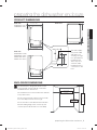 5
5
-
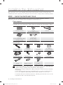 6
6
-
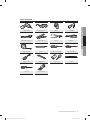 7
7
-
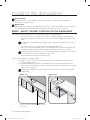 8
8
-
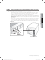 9
9
-
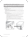 10
10
-
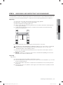 11
11
-
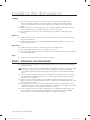 12
12
-
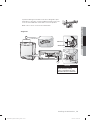 13
13
-
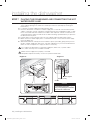 14
14
-
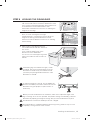 15
15
-
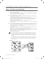 16
16
-
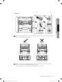 17
17
-
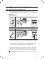 18
18
-
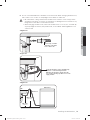 19
19
-
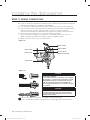 20
20
-
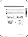 21
21
-
 22
22
-
 23
23
-
 24
24
-
 25
25
-
 26
26
-
 27
27
-
 28
28
-
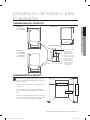 29
29
-
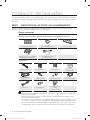 30
30
-
 31
31
-
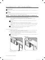 32
32
-
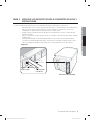 33
33
-
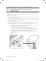 34
34
-
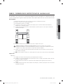 35
35
-
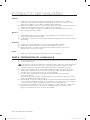 36
36
-
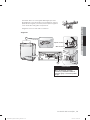 37
37
-
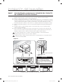 38
38
-
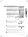 39
39
-
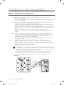 40
40
-
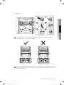 41
41
-
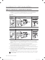 42
42
-
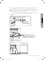 43
43
-
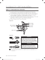 44
44
-
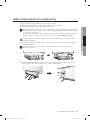 45
45
-
 46
46
-
 47
47
-
 48
48


Samsung DW80H9930US Guía de instalación
- Tipo
- Guía de instalación
- Este manual también es adecuado para
en otros idiomas
Artículos relacionados
-
Samsung DW80M9960UG/AA-00 Guía de instalación
-
-
Samsung DW80R5061UG Guía de instalación
-
Samsung DW80K7050US El manual del propietario
-
Samsung DMT300RFB Guía de instalación
-
-
Samsung DW7933LRAWW Guía de instalación
-
-
-
Otros documentos
-
IKEA VILLKORLIG Dishwasher Manual de usuario
-
Bosch SHE47C05UC/33 Manual de usuario
-
LG LDS5040ST/00 Guía de instalación
-
Bertazzoni DW18S2IPV El manual del propietario
-
-
Bertazzoni DW24T3IPV Manual de usuario
-
Signature Hardware SH449594 Guía de instalación
-
Dacor DDW24M999US Guía de instalación