Lo siento, pero no tengo acceso a ninguna información sobre el dispositivo GE JNM3184DPBB. Por lo tanto, no puedo extraer información del manual de instrucciones para proporcionar una descripción en español de las capacidades del dispositivo.
Lo siento, pero no tengo acceso a ninguna información sobre el dispositivo GE JNM3184DPBB. Por lo tanto, no puedo extraer información del manual de instrucciones para proporcionar una descripción en español de las capacidades del dispositivo.

C
A
B
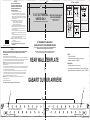
NOTE: IT IS VERY IMPORTANT TO
READ AND FOLLOW THE DIRECTIONS
IN THE INSTALLATION INSTRUCTIONS
BEFORE PROCEEDING WITH THIS
REAR WALL TEMPLATE.
1/4″
C
L
CAUTION – IF EXHAUST ADAPTOR IS POSITIONED OUTSIDE RECOMMENDED DIMENSION,
GREASE-LADEN AIR WILL DISCHARGE INTO HOUSE STRUCTURE.
MISE EN GARDE : SI LE MANCHON EST PLACÉ HORS DE LA DIMENSION RECOMMANDÉE,
LA GRAISSE ET L’AIR SERONT ÉVACUÉS VERS LA STRUCTURE DE LA MAISON
F. CUT OUT FOR WALL
VENTED ONLY
WARNING - TO REDUCE THE RISK OF FIRE AND ELECTRIC SHOCK,
INSTALL AT LEAST 13-3/4 INCHES ABOVE A COOKTOP(OR RANGE)
SUITABLE FOR USE ABOVE GAS OR ELECTRIC
COOKING EQUIPMENT 36 INCHES OR LESS WIDE.
CONVIENT POUR L’UTILISATION AU-DESSUS D’UN ÉQUIPEMENT DE CUISSON
AU GAZ OU ÉLECTRIQUE D’UNE LARGEUR DE 36 POUCES OU MOINS.
1. Trim the rear wall template along the dotted line.
2. Center rear wall template in opening by lining up the plumb line on
wall with centerline on template. Then securely tape or tack the rear
wall template in place. Make sure the minimum width is 30 inches and
that the top of the rear wall template is located a minimum of 30 inches
above the cooking surface.
NOTE: If the cabinets are not plumb, adjust the rear wall
template to the cabinets. If the front edge of the
cabinet is lower than the back edge, adjust the
template to be level with the cabinet front.
These holes must be used for mounting. If the holes are not used, the
installation will not be secure. Installer must use these holes for proper
installation.
Use toggle bolts through these holes, unless one of them lines up with a
stud. Use a wood screw for studs.Make sure to use at least 1 lag screw
in stud, and 2 toggle bolts in drywall or the plaster.
NOTE: Cut out the shaded area marked F on the REAR WALL TEMPLATE
for wall-vented.
4. Remove the template from the rear wall
5. RETURN TO AND PROCEED WITH THE INSTALLATION
INSTRUCTIONS.
12″
4″
CUT HOLE THROUGH REAR WALL FOR EXHAUST ADAPTOR
F. DÉCOUPE POUR ÉVACUATION
VERS LE MUR SEULEMENT
TROU DÉCOUPÉ À L’ARRIÈRE POUR LE
MANCHON D’ÉVACUATION
REAR WALL TEMPLATE
GABARIT DU MUR ARRIÈRE
OPTION 1
3. Drill holes at points A and B. Drill at least one additional hole in area C
that lines up with the location of a stud. Where there is a stud, drill a
3/16” hole for wood screws. For holes that do not line up with a stud,
drill 5/8” holes for toggle bolts.
REMARQUE : IL EST TRÈS IMPORTANT DE LIRE ET DE SUIVRE LES DIRECTIVES DES
INSTRUCTIONS D’INSTALLATION AVANT DE COMMENCER AVEC LE GABARIT
DU MUR ARRIÈRE.
1. Découpez le gabarit du mur arrière le long de la ligne pointillée.
2. Centrez le gabarit du mur arrière dans l’ouverture en alignez la ligne d’aplomb du mur avec la ligne centrale du gabarit.
Fixez avec du ruban ou agrafez le gabarit de mur arrière en place. Assurez-vous que la largeur minimum est de 30 pouces
et que le haut du gabarit du mur arrière est situé à un minimum de 30 pouces de la surface de cuisson.
REMARQUE : Si les armoires ne sont pas d’aplomb, ajustez le gabarit du mur arrière avec les armoires.
Si le bord avant de l’armoire est plus bas que le bord arrière, ajustez le gabarit pour qu’il soit à niveau
avec le devant de l’armoire.
Ces trous doivent être utilisés pour le montage. L’installation ne sera pas sécuritaire si ces trous ne sont pas utilisés.
Insérez les boulons à ailettes dans ces trous, en vous assurant qu’au moins l’un d’eux est aligné avec le montant.
Utilisez les vis à bois pour les montants. Assurez-vous qu’au moins un tire-fond se trouve dans le montant et que
les deux boulons à ailettes sont dans la cloison sèche ou le plâtre.
REMARQUE : Découpez la partie ombragée marquée d’un « F » sur le GABARIT DU MUR ARRIÈRE
pour une évacuation vers le mur.
4. Retirez le gabarit du mur arrière.
5. RETOURNEZ AUX INSTRUCTIONS D’INSTALLATION ET CONTINUEZ.
OPTION 1
NOTES:
- 13” Max Cabinet Depth
- 15” deep cabinets require additional steps using an
additional installation kit: JX15BUMP
REMARQUES :
- Profondeur d’armoire de 13 pouces max.
- Les armoires ayant une profondeur de 15 pouces requièrent des
étapes additionnelles pour l’installation de la trousse : JX15BUMP.
31-7000129 Rev. 0 07-20 GEA
OPTION 2 / OPCIÓN 2
STEP 2: Installer uses bracket to make 2 marks. First
mark is made by using the stampled slot in bracket. Second
mark is made on the ouside edge of bracket.
STEP 1: Draw a vertical line on the wall at the center of
the 30” space.
ÉTAPE 1: Dessinez une ligne verticale sur le mur,
au centre de l’espace de 30 pouces.
STEP 4: Installer uses a level to draw a horizontal line
ÉTAPE 4:
L’installateur utilisera un niveau pour tracer la ligne
horizontale rejoignant les deux marques effectués avec la
fente du support tracée.
that connects the two marks made with the stamped slot in
the bracket.
STEP 5: Installer places the mounting bracket on the wall
as shown in the picture. Draw circles on the wall at holes A
ÉTAPE 5:
L’installateur placera le support de montage sur le mur, comme
montré sur l’illustration. Dessinez des cercles sur le mur aux
trous A et B. Dessinez au moins un cercle pour l’emplacement
C. Au moins un cercle DOIT être aligné avec le montant du mur.
and B. Draw at least one circle in area C. At least one circle
MUST line up with a wall stud.
STEP 6: Set mounting bracket aside and drill holes at
all marked locations. If there is a stud, drill a 3/16” hole for
wood screws. For holes that do not line up with a stud, drill a
5/8” hole for a toggle bolt.
ÉTAPE 6: Mettez le support de montage de côté et percez
des trous aux emplacements marqués. En présence d’un
montant, percez un trou de 3/16 pouces pour les vis à bois.
Pour les trous n’étant pas alignées avec un montant, percez
un trou de 5/8 po pour le boulon à ailettes
Make a mark here, along inside
bottom of the stamped slot provided.
Tracez une marque ici, le long du
bord inférieur de la fente prévue à
cet effet.
Make a mark here on
the outside edge of
the bracket.
Tracez une marque
ici pour le bord extérieur
du support.
Horizontal line
Ligne horizontale
A
C
D
B
STEP 3: Installer moves bracket to the other side of the
ÉTAPE 3:
L’installateur déplace le support de l’autre côté de
l’armoire et tracera deux autres marques. Les marques
sont identiques à l’ÉTAPE 2, pour le côté opposé.
cabinets and makes 2 more marks. Marks are the same as
STEP 2, just opposite side.
Make a mark here, along
Tracez une marque ici, le long du
bord inférieur de la fente prévue à
cet effet (comme à l’étape 1).
inside bottom of the stamped
slot provided (same as Step 1).
Make a mark
Tracez une marque
ici pour le bord
extérieur du support.
here on the
outside edge of
the bracket
A
C
B
Place bracket within the lines created in previous steps.
Placez le support entre les lignes dessinées aux étapes précédentes.
L’installateur utilisera le support pour faire deux marques.
La première marque sera utilisée pour tracer la fente du
support. La deuxième marque sera faite sur le bord extérieur
du support
ÉTAPE 2:
Mark hole locations for A, B, and area C.
Marquez les emplacements de trous pour A, B et C.
Printed in China / Imprimé en Chine
MBM67477301
3. Percez des trous aux points A et B. Percez au moins un autre trou pour le point C, alignez avec l’emplacement du montant.
Où un montant est présent, percez un trou de 3/16 po pour les vis à bois. Pour les trous n’étant pas alignés au montant,
percez des trous de 5/8 po pour les boulons à ailettes
30″ MINIMUM WIDTH REQUIRED /
LARGEUR DE 30 POUCES MINIMUM REQUISE
AVERTISSEMENT : POUR RÉDUIRE LES RISQUES D’ÉLECTROCUTION ET D’INCENDIE, INSTALLEZ
À AU MOINS 13 ¾ POUCES AU-DESSUS DE LA SURFACE DE CUISSON (OU DU FOUR).

C
A
B
MBM64980701_01
Printed in China / Impreso en China
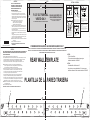
NOTE: IT IS VERY IMPORTANT TO
READ AND FOLLOW THE DIRECTIONS
IN THE INSTALLATION INSTRUCTIONS
BEFORE PROCEEDING WITH THIS
REAR WALL TEMPLATE.
1/4″
C
L
CAUTION – IF EXHAUST ADAPTOR IS POSITIONED OUTSIDE RECOMMENDED DIMENSION, GREASE-LADEN AIR WILL DISCHARGE INTO HOUSE STRUCTURE.
PRECAUCIÓN – SI EL ADAPTADOR DE LA VENTILACIÓN SE POSICIONA FUERA DE LA DIMENSIÓN RECOMENDADA, SE PRODUCIRÁ UNA DESCARGA DE AIRE
CARGADO DE GRASA DENTRO DE LA ESTRUCTURA DE LA CASA.
F. CUT OUT FOR WALL
VENTED ONLY
WARNING - TO REDUCE THE RISK OF FIRE AND ELECTRIC SHOCK,
INSTALL AT LEAST 13-3/4 INCHES ABOVE A COOKTOP(OR RANGE)
SUITABLE FOR USE ABOVE GAS OR ELECTRIC
COOKING EQUIPMENT 36 INCHES OR LESS WIDE.
APTO PARA SU USO SOBRE EQUIPOS ELÉCTRICOS O
A GAS CON ANCHO DE 36 PULGADAS (90CM) O INFERIOR
ADVERTENCIA - PARA REDUCIR EL RIESGO DE INCENDIO Y DE DESCARGA ELÉCTRICA,
INSTALE AL MENOS A 13-3/4 PULGADAS (35CM) SOBRE LA VITROCERÁMICA (O FOGÓN)
30″ MINIMUM WIDTH REQUIRED / ANCHO MÍNIMO REQUERIDO DE 30”
1. Trim the rear wall template along the dotted line.
2. Center rear wall template in opening by lining up the plumb line on
wall with centerline on template. Then securely tape or tack the rear
wall template in place. Make sure the minimum width is 30 inches and
that the top of the rear wall template is located a minimum of 30 inches
above the cooking surface.
NOTE: If the cabinets are not plumb, adjust the rear wall
template to the cabinets. If the front edge of the
cabinet is lower than the back edge, adjust the
template to be level with the cabinet front.
These holes must be used for mounting. If the holes are not used, the
installation will not be secure. Installer must use these holes for proper
installation.
Use toggle bolts through these holes, unless one of them lines up with a
stud. Use a wood screw for studs.Make sure to use at least 1 lag screw
in stud, and 2 toggle bolts in drywall or the plaster.
NOTE: Cut out the shaded area marked F on the REAR WALL TEMPLATE
for wall-vented.
4. Remove the template from the rear wall
5. RETURN TO AND PROCEED WITH THE INSTALLATION
INSTRUCTIONS.
12″
4″
CUT HOLE THROUGH REAR WALL FOR EXHAUST ADAPTOR
F. REALICE EL RECORTE SÓLO
PARA PAREDES VENTILADAS
RECORTE EL AGUJERO EN LA PARED TRASERA PARA
EL ADAPTADOR DE LA VENTILACIÓN
REAR WALL TEMPLATE
PLANTILLA DE LA PARED TRASERA
OPTION 1
3. Drill holes at points A and B. Drill at least one additional hole in area C
that lines up with the location of a stud. Where there is a stud, drill a
3/16” hole for wood screws. For holes that do not line up with a stud,
drill 5/8” holes for toggle bolts.
NOTA: ES MUY IMPORTANTE LEER Y SEGUIR INDICACIONES QUE FIGURAN EN LAS
INSTRUCCIONES DE INSTALACIÓN ANTES DE PROCEDER CON ESTA PLANTILLA
DE LA PARED TRASERA.
1. Recorte la plantilla de la pared trasera a lo largo de la línea de puntos.
2. Centre la plantilla de la pared trasera en la abertura, alineando la línea de la tubería sobre la pared con la línea
central de la plantilla. Luego encinte o sujete de forma segura la plantilla de la pared trasera en su posición.
Asegúrese de que el ancho mínimo posea 30 pulgadas y que la parte superior de la plantilla
de la pared trasera se encuentre ubicada a un mínimo de 30 pulgadas sobre la superficie de cocción.
NOTA: Si los gabinetes no se encuentran en posición vertical, ajuste la plantilla de la pared
trasera con los gabinetes. Si el extremo frontal del gabinete es inferior al extremo trasero,
ajuste la plantilla para que esté nivelada con el frente del gabinete.
Se deberán usar estos agujeros para el montaje. Si no se usan los agujeros, la instalación
no será segura. El instalador deberá usar estos agujeros para una instalación adecuada.
Use tornillos con resorte a través de estos agujeros, a menos que uno de estos quede alineado
con un montaje. Use un tornillo de madera para los montajes. Asegúrese de usar por lo menos
1 tornillo tirafondo en el montaje, y 2 tornillos con resorte en la pared de yeso o revoque.
NOTA: Recorte el área sombreada con la marca F sobre la PLANTILLA DE LA PARED TRASERA
para la ventilación de pared.
4. Retire la plantilla de la pared trasera.
5. REGRESE A Y PROCEDA CON LAS INSTRUCCIONES DE INSTALACIÓN.
OPCIÓN 1
3. Perfore agujeros en los puntos A y B. Perfore por lo menos un agujero adicional en el área C,
de modo que esté alineado con la ubicación de un montaje. Donde haya un montaje, perfore
un agujero de 3/16” para tornillos de madera. Para aquellos agujeros que no estén alineados
con un montaje, perfore agujeros de 5/8” para tornillos con resorte.
NOTES:
- 13” Max Cabinet Depth
- 15” deep cabinets require additional steps using an
additional installation kit: JX15BUMP
NOTAS:
- Profundidad Máx. del Gabinete de 13”
- Los gabinetes con una profundidad de 15” requieren pasos
adicionales utilizando el kit de instalación adicional: JX15BUMP
OPTION 2 / OPCIÓN 2
STEP 2: Installer uses bracket to make 2 marks. First
El instalador deberá usar un soporte para realizar 2 marcas.
La primera marca se deberá realizar usando la ranura
estampada en el soporte. La segunda marca se deberá
realizar sobre el extremo exterior del soporte.
mark is made by using the stampled slot in bracket. Second
mark is made on the ouside edge of bracket.
STEP 1: Draw a vertical line on the wall at the center of
the 30” space.
PASO 1: Dibuje una línea vertical sobre la pared,
en el centro del espacio de 30”.
STEP 4: Installer uses a level to draw a horizontal line
PASO 4:
El instalador deberá usar un nivel para dibujar una línea
horizontal que conecte las dos marcas realizadas con
la ranura estampada en el soporte.
that connects the two marks made with the stamped slot in
the bracket.
STEP 5: Installer places the mounting bracket on the wall
as shown in the picture. Draw circles on the wall at holes A
PASO 5:
El instalador deberá colocar el soporte de montaje sobre
la pared, como se muestra en la imagen. Dibuje círculos
en la pared sobre los agujeros A y B. Dibuje por lo menos
un círculo en el área C. Por lo menos un círculo se DEBERÁ
alinear con una ranura de pared.
and B. Draw at least one circle in area C. At least one circle
MUST line up with a wall stud.
STEP 6: Set mounting bracket aside and drill holes at
all marked locations. If there is a stud, drill a 3/16” hole for
wood screws. For holes that do not line up with a stud, drill a
5/8” hole for a toggle bolt.
PASO 6: Deje el soporte de montaje a un costado y perfore
agujeros en todas las ubicaciones marcadas. Si hay un
montaje, haga un agujero de 3/16” para tornillos de madera.
Para aquellos agujeros que no estén alineados con un montaje,
perfore un agujero de 5/8” para un tornillo con resorte.
Make a mark here, along inside
bottom of the stamped slot provided.
Realice una marca aquí, a lo largo
de la parte inferior interna de la
ranura estampada provista.
Make a mark here on
the outside edge of
the bracket.
Realice una marca
aquí sobre el extremo
exterior del soporte.
Horizontal line
Línea horizontal
A
C
D
B
STEP 3: Installer moves bracket to the other side of the
PASO 3:
El instalador deberá mover el soporte hasta el otro lado
de los gabinetes y realizar otras 2 marcas. Las marcas son
iguales que en el PASO 2, sólo que del lado opuesto.
cabinets and makes 2 more marks. Marks are the same as
STEP 2, just opposite side.
Make a mark here, along
Realice una marca aquí, a lo largo
de la parte inferior interna
de la ranura estampada provista
(igual que en el Paso 1).
inside bottom of the stamped
slot provided (same as Step 1).
Make a mark
Realice una
marca aquí sobre
el extremo exterior
del soporte
here on the
outside edge of
the bracket
A
C
B
Place bracket within the lines created in previous steps.
Coloque el soporte dentro de las líneas creadas en los pasos anteriores.
PASO 2:
Mark hole locations for A, B, and area C.
Marque las ubicaciones de los agujeros de las áreas A, B y C.
31-7000129 Rev. 0 07-20 GEA
Transcripción de documentos
1/4″ OPTION 1 NOTE: IT IS VERY IMPORTANT TO READ AND FOLLOW THE DIRECTIONS IN THE INSTALLATION INSTRUCTIONS BEFORE PROCEEDING WITH THIS REAR WALL TEMPLATE. 2. Center rear wall template in opening by lining up the plumb line on wall with centerline on template. Then securely tape or tack the rear wall template in place. Make sure the minimum width is 30 inches and that the top of the rear wall template is located a minimum of 30 inches above the cooking surface. NOTE: If the cabinets are not plumb, adjust the rear wall template to the cabinets. If the front edge of the cabinet is lower than the back edge, adjust the template to be level with the cabinet front. 3. Drill holes at points A and B. Drill at least one additional hole in area C that lines up with the location of a stud. Where there is a stud, drill a 3/16” hole for wood screws. For holes that do not line up with a stud, drill 5/8” holes for toggle bolts. These holes must be used for mounting. If the holes are not used, the installation will not be secure. Installer must use these holes for proper installation. Use toggle bolts through these holes, unless one of them lines up with a stud. Use a wood screw for studs.Make sure to use at least 1 lag screw in stud, and 2 toggle bolts in drywall or the plaster. NOTE: Cut out the shaded area marked F on the REAR WALL TEMPLATE for wall-vented. Printed in China / Imprimé en Chine STEP 1: Draw a vertical line on the wall at the center of 12″ 1. Trim the rear wall template along the dotted line. MBM67477301 4″ the 30” space. F. CUT OUT FOR WALL VENTED ONLY CUT HOLE THROUGH REAR WALL FOR EXHAUST ADAPTOR TROU DÉCOUPÉ À L’ARRIÈRE POUR LE MANCHON D’ÉVACUATION B D C A au centre de l’espace de 30 pouces. STEP 2: Installer uses bracket to make 2 marks. First mark is made by using the stampled slot in bracket. Second mark is made on the ouside edge of bracket. Make a mark here, along inside bottom of the stamped slot provided (same as Step 1). Tracez une marque ici, le long du bord inférieur de la fente prévue à cet effet (comme à l’étape 1). Make a mark here on the outside edge of the bracket Tracez une marque ici pour le bord extérieur du support. ÉTAPE 3: L’installateur déplace le support de l’autre côté de l’armoire et tracera deux autres marques. Les marques sont identiques à l’ÉTAPE 2, pour le côté opposé. A B C Place bracket within the lines created in previous steps. Placez le support entre les lignes dessinées aux étapes précédentes. ÉTAPE 5: L’installateur placera le support de montage sur le mur, comme montré sur l’illustration. Dessinez des cercles sur le mur aux trous A et B. Dessinez au moins un cercle pour l’emplacement C. Au moins un cercle DOIT être aligné avec le montant du mur. STEP 6: Set mounting bracket aside and drill holes at all marked locations. If there is a stud, drill a 3/16” hole for wood screws. For holes that do not line up with a stud, drill a 5/8” hole for a toggle bolt. ÉTAPE 6: Tracez une marque ici pour le bord extérieur du support. Make a mark here, along inside bottom of the stamped slot provided. ÉTAPE 2: Tracez une marque ici, le long du bord inférieur de la fente prévue à cet effet. L’installateur utilisera le support pour faire deux marques. La première marque sera utilisée pour tracer la fente du support. La deuxième marque sera faite sur le bord extérieur du support Mettez le support de montage de côté et percez des trous aux emplacements marqués. En présence d’un montant, percez un trou de 3/16 pouces pour les vis à bois. Pour les trous n’étant pas alignées avec un montant, percez un trou de 5/8 po pour le boulon à ailettes Horizontal line ÉTAPE 4: Ligne horizontale L’installateur utilisera un niveau pour tracer la ligne horizontale rejoignant les deux marques effectués avec la fente du support tracée. 30″ MINIMUM WIDTH REQUIRED / LARGEUR DE 30 POUCES MINIMUM REQUISE CAUTION – IF EXHAUST ADAPTOR IS POSITIONED OUTSIDE RECOMMENDED DIMENSION, GREASE-LADEN AIR WILL DISCHARGE INTO HOUSE STRUCTURE. MISE EN GARDE : SI LE MANCHON EST PLACÉ HORS DE LA DIMENSION RECOMMANDÉE, LA GRAISSE ET L’AIR SERONT ÉVACUÉS VERS LA STRUCTURE DE LA MAISON 1. Découpez le gabarit du mur arrière le long de la ligne pointillée. 2. Centrez le gabarit du mur arrière dans l’ouverture en alignez la ligne d’aplomb du mur avec la ligne centrale du gabarit. Fixez avec du ruban ou agrafez le gabarit de mur arrière en place. Assurez-vous que la largeur minimum est de 30 pouces et que le haut du gabarit du mur arrière est situé à un minimum de 30 pouces de la surface de cuisson. REMARQUE : Si les armoires ne sont pas d’aplomb, ajustez le gabarit du mur arrière avec les armoires. Si le bord avant de l’armoire est plus bas que le bord arrière, ajustez le gabarit pour qu’il soit à niveau avec le devant de l’armoire. REAR WALL TEMPLATE 3. Percez des trous aux points A et B. Percez au moins un autre trou pour le point C, alignez avec l’emplacement du montant. Où un montant est présent, percez un trou de 3/16 po pour les vis à bois. Pour les trous n’étant pas alignés au montant, percez des trous de 5/8 po pour les boulons à ailettes CL Ces trous doivent être utilisés pour le montage. L’installation ne sera pas sécuritaire si ces trous ne sont pas utilisés. 5. RETOURNEZ AUX INSTRUCTIONS D’INSTALLATION ET CONTINUEZ. F. DÉCOUPE POUR ÉVACUATION VERS LE MUR SEULEMENT ÉTAPE 1: Dessinez une ligne verticale sur le mur, Make a mark here on the outside edge of the bracket. REMARQUE : IL EST TRÈS IMPORTANT DE LIRE ET DE SUIVRE LES DIRECTIVES DES INSTRUCTIONS D’INSTALLATION AVANT DE COMMENCER AVEC LE GABARIT DU MUR ARRIÈRE. 4. Retirez le gabarit du mur arrière. STEP 5: Installer places the mounting bracket on the wall as shown in the picture. Draw circles on the wall at holes A and B. Draw at least one circle in area C. At least one circle MUST line up with a wall stud. Mark hole locations for A, B, and area C. Marquez les emplacements de trous pour A, B et C. that connects the two marks made with the stamped slot in the bracket. OPTION 1 REMARQUE : Découpez la partie ombragée marquée d’un « F » sur le GABARIT DU MUR ARRIÈRE pour une évacuation vers le mur. STEP 3: Installer moves bracket to the other side of the cabinets and makes 2 more marks. Marks are the same as STEP 2, just opposite side. STEP 4: Installer uses a level to draw a horizontal line 4. Remove the template from the rear wall 5. RETURN TO AND PROCEED WITH THE INSTALLATION INSTRUCTIONS. Insérez les boulons à ailettes dans ces trous, en vous assurant qu’au moins l’un d’eux est aligné avec le montant. Utilisez les vis à bois pour les montants. Assurez-vous qu’au moins un tire-fond se trouve dans le montant et que les deux boulons à ailettes sont dans la cloison sèche ou le plâtre. OPTION 2 / OPCIÓN 2 NOTES: - 13” Max Cabinet Depth - 15” deep cabinets require additional steps using an additional installation kit: JX15BUMP REMARQUES : - Profondeur d’armoire de 13 pouces max. - Les armoires ayant une profondeur de 15 pouces requièrent des étapes additionnelles pour l’installation de la trousse : JX15BUMP. GABARIT DU MUR ARRIÈRE B A C WARNING - TO REDUCE THE RISK OF FIRE AND ELECTRIC SHOCK, INSTALL AT LEAST 13-3/4 INCHES ABOVE A COOKTOP(OR RANGE) SUITABLE FOR USE ABOVE GAS OR ELECTRIC COOKING EQUIPMENT 36 INCHES OR LESS WIDE. CONVIENT POUR L’UTILISATION AU-DESSUS D’UN ÉQUIPEMENT DE CUISSON AU GAZ OU ÉLECTRIQUE D’UNE LARGEUR DE 36 POUCES OU MOINS. AVERTISSEMENT : POUR RÉDUIRE LES RISQUES D’ÉLECTROCUTION ET D’INCENDIE, INSTALLEZ À AU MOINS 13 ¾ POUCES AU-DESSUS DE LA SURFACE DE CUISSON (OU DU FOUR). 31-7000129 Rev. 0 07-20 GEA 1/4″ OPTION 1 NOTE: IT IS VERY IMPORTANT TO READ AND FOLLOW THE DIRECTIONS IN THE INSTALLATION INSTRUCTIONS BEFORE PROCEEDING WITH THIS REAR WALL TEMPLATE. 2. Center rear wall template in opening by lining up the plumb line on wall with centerline on template. Then securely tape or tack the rear wall template in place. Make sure the minimum width is 30 inches and that the top of the rear wall template is located a minimum of 30 inches above the cooking surface. NOTE: If the cabinets are not plumb, adjust the rear wall template to the cabinets. If the front edge of the cabinet is lower than the back edge, adjust the template to be level with the cabinet front. 3. Drill holes at points A and B. Drill at least one additional hole in area C that lines up with the location of a stud. Where there is a stud, drill a 3/16” hole for wood screws. For holes that do not line up with a stud, drill 5/8” holes for toggle bolts. These holes must be used for mounting. If the holes are not used, the installation will not be secure. Installer must use these holes for proper installation. Use toggle bolts through these holes, unless one of them lines up with a stud. Use a wood screw for studs.Make sure to use at least 1 lag screw in stud, and 2 toggle bolts in drywall or the plaster. NOTE: Cut out the shaded area marked F on the REAR WALL TEMPLATE for wall-vented. 4. Remove the template from the rear wall 5. RETURN TO AND PROCEED WITH THE INSTALLATION INSTRUCTIONS. Printed in China / Impreso en China OPCIÓN 1 1. Recorte la plantilla de la pared trasera a lo largo de la línea de puntos. 2. Centre la plantilla de la pared trasera en la abertura, alineando la línea de la tubería sobre la pared con la línea central de la plantilla. Luego encinte o sujete de forma segura la plantilla de la pared trasera en su posición. Asegúrese de que el ancho mínimo posea 30 pulgadas y que la parte superior de la plantilla de la pared trasera se encuentre ubicada a un mínimo de 30 pulgadas sobre la superficie de cocción. Se deberán usar estos agujeros para el montaje. Si no se usan los agujeros, la instalación no será segura. El instalador deberá usar estos agujeros para una instalación adecuada. Use tornillos con resorte a través de estos agujeros, a menos que uno de estos quede alineado con un montaje. Use un tornillo de madera para los montajes. Asegúrese de usar por lo menos 1 tornillo tirafondo en el montaje, y 2 tornillos con resorte en la pared de yeso o revoque. NOTA: Recorte el área sombreada con la marca F sobre la PLANTILLA DE LA PARED TRASERA para la ventilación de pared. 4″ the 30” space. F. CUT OUT FOR WALL VENTED ONLY CUT HOLE THROUGH REAR WALL FOR EXHAUST ADAPTOR STEP 3: Installer moves bracket to the other side of the cabinets and makes 2 more marks. Marks are the same as STEP 2, just opposite side. STEP 5: Installer places the mounting bracket on the wall as shown in the picture. Draw circles on the wall at holes A and B. Draw at least one circle in area C. At least one circle MUST line up with a wall stud. Mark hole locations for A, B, and area C. Marque las ubicaciones de los agujeros de las áreas A, B y C. F. REALICE EL RECORTE SÓLO PARA PAREDES VENTILADAS RECORTE EL AGUJERO EN LA PARED TRASERA PARA EL ADAPTADOR DE LA VENTILACIÓN PASO 1: Dibuje una línea vertical sobre la pared, B D C A en el centro del espacio de 30”. STEP 2: Installer uses bracket to make 2 marks. First mark is made by using the stampled slot in bracket. Second mark is made on the ouside edge of bracket. Make a mark here, along inside bottom of the stamped slot provided (same as Step 1). Realice una marca aquí, a lo largo de la parte inferior interna de la ranura estampada provista (igual que en el Paso 1). Make a mark here on the outside edge of the bracket Realice una marca aquí sobre el extremo exterior del soporte PASO 2: El instalador deberá usar un soporte para realizar 2 marcas. La primera marca se deberá realizar usando la ranura estampada en el soporte. La segunda marca se deberá realizar sobre el extremo exterior del soporte. Place bracket within the lines created in previous steps. Coloque el soporte dentro de las líneas creadas en los pasos anteriores. PASO 5: El instalador deberá colocar el soporte de montaje sobre la pared, como se muestra en la imagen. Dibuje círculos en la pared sobre los agujeros A y B. Dibuje por lo menos un círculo en el área C. Por lo menos un círculo se DEBERÁ alinear con una ranura de pared. STEP 4: Installer uses a level to draw a horizontal line STEP 6: Set mounting bracket aside and drill holes at all marked locations. If there is a stud, drill a 3/16” hole for wood screws. For holes that do not line up with a stud, drill a 5/8” hole for a toggle bolt. that connects the two marks made with the stamped slot in the bracket. Make a mark here, along inside bottom of the stamped slot provided. Realice una marca aquí, a lo largo de la parte inferior interna de la ranura estampada provista. B C PASO 3: El instalador deberá mover el soporte hasta el otro lado de los gabinetes y realizar otras 2 marcas. Las marcas son iguales que en el PASO 2, sólo que del lado opuesto. Make a mark here on the outside edge of the bracket. Realice una marca aquí sobre el extremo exterior del soporte. A PASO 6: Deje el soporte de montaje a un costado y perfore agujeros en todas las ubicaciones marcadas. Si hay un montaje, haga un agujero de 3/16” para tornillos de madera. Para aquellos agujeros que no estén alineados con un montaje, perfore un agujero de 5/8” para un tornillo con resorte. Horizontal line PASO 4: Línea horizontal El instalador deberá usar un nivel para dibujar una línea horizontal que conecte las dos marcas realizadas con la ranura estampada en el soporte. 30″ MINIMUM WIDTH REQUIRED / ANCHO MÍNIMO REQUERIDO DE 30” CAUTION – IF EXHAUST ADAPTOR IS POSITIONED OUTSIDE RECOMMENDED DIMENSION, GREASE-LADEN AIR WILL DISCHARGE INTO HOUSE STRUCTURE. NOTA: ES MUY IMPORTANTE LEER Y SEGUIR INDICACIONES QUE FIGURAN EN LAS INSTRUCCIONES DE INSTALACIÓN ANTES DE PROCEDER CON ESTA PLANTILLA DE LA PARED TRASERA. NOTA: Si los gabinetes no se encuentran en posición vertical, ajuste la plantilla de la pared trasera con los gabinetes. Si el extremo frontal del gabinete es inferior al extremo trasero, ajuste la plantilla para que esté nivelada con el frente del gabinete. 3. Perfore agujeros en los puntos A y B. Perfore por lo menos un agujero adicional en el área C, de modo que esté alineado con la ubicación de un montaje. Donde haya un montaje, perfore un agujero de 3/16” para tornillos de madera. Para aquellos agujeros que no estén alineados con un montaje, perfore agujeros de 5/8” para tornillos con resorte. STEP 1: Draw a vertical line on the wall at the center of 12″ 1. Trim the rear wall template along the dotted line. MBM64980701_01 OPTION 2 / OPCIÓN 2 PRECAUCIÓN – SI EL ADAPTADOR DE LA VENTILACIÓN SE POSICIONA FUERA DE LA DIMENSIÓN RECOMENDADA, SE PRODUCIRÁ UNA DESCARGA DE AIRE CARGADO DE GRASA DENTRO DE LA ESTRUCTURA DE LA CASA. REAR WALL TEMPLATE CL NOTES: - 13” Max Cabinet Depth - 15” deep cabinets require additional steps using an additional installation kit: JX15BUMP NOTAS: - Profundidad Máx. del Gabinete de 13” - Los gabinetes con una profundidad de 15” requieren pasos adicionales utilizando el kit de instalación adicional: JX15BUMP PLANTILLA DE LA PARED TRASERA 4. Retire la plantilla de la pared trasera. 5. REGRESE A Y PROCEDA CON LAS INSTRUCCIONES DE INSTALACIÓN. B A C WARNING - TO REDUCE THE RISK OF FIRE AND ELECTRIC SHOCK, INSTALL AT LEAST 13-3/4 INCHES ABOVE A COOKTOP(OR RANGE) SUITABLE FOR USE ABOVE GAS OR ELECTRIC COOKING EQUIPMENT 36 INCHES OR LESS WIDE. APTO PARA SU USO SOBRE EQUIPOS ELÉCTRICOS O A GAS CON ANCHO DE 36 PULGADAS (90CM) O INFERIOR ADVERTENCIA - PARA REDUCIR EL RIESGO DE INCENDIO Y DE DESCARGA ELÉCTRICA, INSTALE AL MENOS A 13-3/4 PULGADAS (35CM) SOBRE LA VITROCERÁMICA (O FOGÓN) 31-7000129 Rev. 0 07-20 GEA-
 1
1
-
 2
2


GE JNM3184DPBB Template
- Tipo
- Template
- Este manual también es adecuado para
Lo siento, pero no tengo acceso a ninguna información sobre el dispositivo GE JNM3184DPBB. Por lo tanto, no puedo extraer información del manual de instrucciones para proporcionar una descripción en español de las capacidades del dispositivo.
en otros idiomas
- français: GE JNM3184DPBB
- English: GE JNM3184DPBB