
1
Item #1002-368-503
Model #7136-01
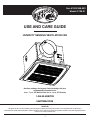
USE AND CARE GUIDE
HUMIDITY SENSING VENTILATION FAN
Questions, problems, missing parts? Before returning to the store,
call Hampton Bay Customer Service
8 a.m. - 7 p.m., EST, Monday-Friday, 9 a.m. - 6 p.m., EST, Saturday
1-855-HD-HAMPTON
HAMPTONBAY.COM
THANK YOU
We appreciate the trust and confidence you have placed in Hampton Bay through the purchase of this ventilating bath fan. We strive to
continually create quality products designed to enhance your home. Visit us online to see our full line of products available for your home improvement needs.
Thank you for choosing Hampton Bay!

2
Table of Contents ........................................................... 2
Safety Information .......................................................... 2
Product Specications ................................................... 3
Typical Installation .......................................................... 3
Wiring Diagram ............................................................... 3
Quick connector instructions ...................................................3
Warranty .......................................................................... 4
LIMITED LIFETIME WARRANTY ................................................4
What is Covered......................................................................4
Pre-installation................................................................ 4
Planning Installation ................................................................4
Tools Required ........................................................................4
Package Contents ...................................................................5
Installation - New Construction .................................... 6
Installation - Existing Construction .............................. 8
Humidity Sensor Operation ......................................... 10
Care and Maintenance ................................................. 11
Troubleshooting ............................................................ 11
Table of Contents
Safety Information
Please read and understand this entire manual before attempting to assemble, operate or install the
product.
1. Always disconnect the power supply prior to servicing the fan, motor or junction box.
2. Follow all local building, safety and electrical codes as well as NEC (National Electrical Code) and OSHA (Occupational Safety and Health Act).
3. Electric Service supply must be 120 volts, 60 hertz.
4. This product must properly connect to the grounding conductor of the supply circuit.
5. Do not bend or kink the power wires.
6. Do not use this fan with any solid state control device, such as a remote control, dimmer switch, or certain timers. Mechanical timers are not
solid state devices.
7. Do not install in a ceiling with insulation greater than R50.
8. Duct work should be installed in a straight line with minimal bends.
9. Duct work size must be the same size as the discharge and should not be reduced. Reducing the duct size may increase fan noise.
WARNING: To reduce the risk of re, electric shock, or injury to persons, observe the following:
1. Use this unit in the manner intended by the manufacturer. If you have any questions. Please call customer service.
2. Before servicing or cleaning unit, switch power off at service panel and lock the service disconnecting means to prevent power from being
switched on accidentally. When the service disconnecting means cannot be locked, securely fasten a prominent warning device, such as a tag,
to the service panel.
3. Installation work and electrical wiring must be done by a qualied person(s) in accordance with all applicable codes and standards, including
re-rated construction.
4. Sufcient air is needed for proper combustion and exhausting of gases through the ue (chimney) of fuel burning equipment to prevent backdrafting.
Follow the heating equipment manufacturer’s guideline and safety standards such as those published by the National Fire Protection Association
(NFPA), and the American Society for Heating, Refrigeration and Air Conditioning Engineers (ASHRAE) and local code authorities.
5. When cutting or drilling into the wall or ceiling, do not damage electrical wiring and other hidden utilities.
6. Ducted fans must always be vented to the outdoors.
7. If this unit is to be installed over a tub or shower, it must be marked as appropriate for the application and be connected to a GFCI (Ground Fault
Circuit Interrupter) – protected branch circuit.
CAUTION: For general ventilating use only. Do not use to exhaust hazardous or explosive materials and vapors.
CAUTION: Not for use in cooking areas.
CAUTION: To reduce the risk of injury to persons, install the fan at least 7 feet (2.1m) above the oor.

3
HAMPTONBAY.COM
Please contact 1-855-HD-HAMPTON for further assistance.
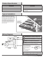
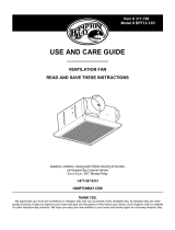
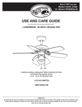
Product Specication
Typical Installation
Wiring Diagram
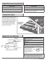
SPECIFICATIONS SPECIFICATIONS
Airow: 140 CFM Power consumption: 48 W
120 V, 60 Hz Weight: 10.78 lbs.
Duct diameter: 6 in.
Ceiling Opening Dimension Requirements: 10-13/16 in. (L) x 10-1/2 in.
(W) x 8-1/2 in. (H)
Sound output: 1.0 Sones
The ducting from this fan to the outside of the
building has a strong effect on the air ow, noise and
energy use of the fan. Use the shortest, straightest
duct routing possible for best performance, and
avoid installing the fan with smaller ducts than
recommended. Insulation around the ducts can
reduce energy loss and inhibit mold growth. Fans
installed with existing ducts may not achieve
their rated air ow.
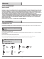
WARNING: Wiring must comply with all applicable electrical
codes. Turn OFF power before removing or installing connectors
WARNING: COPPER TO COPPER ONLY. Do not use Aluminum wire.
CAUTION: Accessory part (quick connector) should meet
NOTE: The connector is reusable on solid wires of the same wire gage
or smaller. Do not reuse the connector on stranded wires
.
• Strip wires 3/8 in. - 1/2 in.
• Grip the wire firmly and push
the stripped end of the wire into
the open port of the connector.
Use only one conductor
per port.
• Verify the stripped end of the
wires is fully inserted to the
back of the connector.
Quick
connect
House
wires
Product
wires
NOTE: Important wire information. Maximum temperature rating 105˚C
(221˚F). 600 volts maximum for building wire and 1000 volts maximum
for building wire and 1000 volts maximum in signs and lighting xtures.
The acceptable wire range includes: Solid: 12-18 AWG.
OR
Roof cap (with
built-in damper)
Caulk
termination
to duct
Wall cap
(with
built-in
damper)
Properly insulate
around fan to
minimize building
heat loss and gain
Fan housing
Seal any gap around
fan housing
2-3 foot straight run
before elbow
duct helps alignment
and absorbs sound

4
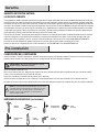
LIMITED LIFETIME WARRANTY
WHAT IS COVERED
If this product fails due to a defect in materials or workmanship at any time during the rst FIVE years of ownership, the manufacturer will replace it free
of charge, postage-paid at their option. This warranty does not cover products that have been abused, altered, damaged, misused, cut or worn. This
warranty does not cover use in commercial applications. Use only manufacturer-supplied genuine warranty repair replacement parts to repair this fan. Use of
non-genuine repair parts will void your warranty. The manufacturer DISCLAIMS all other implied or express warranties including all warranties of merchant-
ability and/or tness for a particular purpose. As some states do not allow exclusions or limitations on an implied warranty, the above exclusions and
limitations may not apply. This warranty gives you specic legal rights, and you may have other rights that vary from state to state.
This warranty is limited to the replacement of defective parts only. Labor charges and/or damage incurred during installation, repair, replacement as well
as incidental and consequential damages connected with the above are excluded. Any damage to this product as a result of neglect, misuse, accident,
improper installation or use other than the purpose SHALL VOID THIS WARRANTY. Shipping costs for return product as part of a claim on the warranty
must be paid for by the customer.
Contact the Customer Service Team at 1-855-HD-HAMPTON or visit www.HAMPTONBAY.com.
Warranty
Pre-installation
PLANNING INSTALLATION
Before beginning assembly of the product, make sure all parts are present. Compare parts with the package contents list and hardware contents. If
any part is missing or damaged, do not attempt to assemble the product.
WARNING: Turn off electricity at breaker box before beginning
installation.
Carefully remove the unit from the carton.
Check area above installation location to be sure that wiring can run to the planned location and that duct work can be run and the area is sufcient
for proper ventilation.
Inspect duct work and wiring before proceeding with installation.
Before installation, provide inspection and future maintenance access at a location that will not interfere with installation work.
You may need the help of a second person to install this fan; one person on the attic side and one on the room side.
NOTE: Installation may vary depending on how the previous bath fan
was installed. Supplies necessary for the installation of your bath fan are
not all included. However, most are available at your local home
improvement or hardware store.
TOOLS REQUIRED (not included)
Claw
hammer
Drill
bits
Flathead
screwdriver
Duct
tape
Phillips head
screwdriver
Utility
knife
Electric
drill

5
HAMPTONBAY.COM
Please contact 1-855-HD-HAMPTON for further assistance.
Pre-installation (continued)
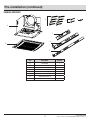
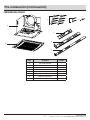
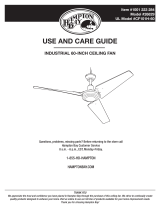
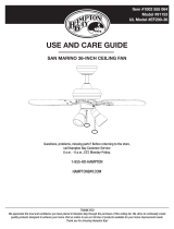
PACKAGE CONTENTS
A
B
F
G
H
C
D
E
Part Description Quantity
A Fan housing 1
B Grille 1
C Long wood screws (M4x30mm) 8
D Machine screw (M4x12mm) 2
E Short machine screw (M4x10mm) 1
F Suspension bracket I 1
G Suspension bracket II 1
H Suspension bracket III 1

6
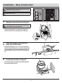
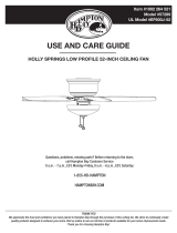
Installation - New Construction
CAUTION: Make sure power is switched off at service
panel before starting installation.
NOTE: Ceiling mount only.
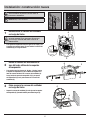
1
Attaching fan housing to the ceiling joist
CAUTION: Allow for the thickness of ceiling board used
in your application. Do not ush mount to joist. Flange
should be ush with the ceiling board.
If spacing between joists is 12 in. apart, use 4 long wood
screws (C) to attach the fan housing (A) to the ceiling joist
2
Attach fan housing to the ceiling joist
using suspension brackets
If spacing between joists is 16 in. - 24 in., insert suspension
bracket I (F) into the bracket cover on the duct connector side
of the fan housing (A). Then, attach suspension bracket II (G)
and suspension bracket III (H) to the back of the fan housing
(A).
3
Securing fan housing to ceiling joist
Secure the fan housing (A) to the joist with suspension brackets
(G, H) using long wood screws (C).
A
A
C
F
G
A
C
G, H
H
0.24"

7
HAMPTONBAY.COM
Please contact 1-855-HD-HAMPTON for further assistance.
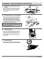
Installation - New Construction (continued)
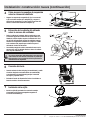
4
Securing suspensions brackets onto fan
housing
Secure suspension brackets (G, H) to the fan housing (A)
using the two machine screws (D) and secure suspension
bracket (F) to the other side of housing using the short
machine screw (E).
5
Removing wiring cover on the fan housing
Quick
Connector
Product
Wires
House
Wires
Remove the wiring cover. Pull the house wires through the
wire box cover hole (5.1). Using the quick connector, secure
120 V AC house wiring from the wall switch to the fan as
shown in the wiring diagram on page 3. 14 AWG is the small-
est conductor that should be used for branch circuit wiring.
Carefully push the connected wires back into the wiring box
housing. Reattach the wiring box cover (5.1).
CAUTION: If the electrical wires do not match the colors
listed, you must determine what each house wire represents
before connecting. You may need to consult an electrical
contractor to determine safely.
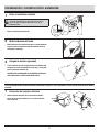
6
Connecting the duct
Connect a 6 in. circular duct (not supplied) and vent to the
outside. Secure it with duct tape (not supplied) or a clamp (not
supplied) to make the connection secure and air tight.
Turn on the power source. Check the fan for any abnormal
sound or vibration.
7
Installing the grille
Attach the grille (B) by pinching the mounting springs and
inserting into the narrow rectangular slots in the fan housing (A).
A
B
E
F
G, H
5.1
A
D

8
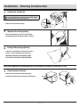
Installation - Existing Construction
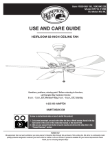
1
Remove the existing fan
CAUTION: Allow for the thickness of ceiling board used
in your application. Do not ush mount to joist. Flange
should be ush with the ceiling board.
Remove the old fan from the ceiling.
2
Measure the ceiling opening
1
1
1
1
0
9
8
7
6
5
4
Measure the opening to ensure it is large enough to
accommodate the new fan body (A) (10.25 in. x 10.25 in.).
3
Enlarge the opening (optional)
10.25"
10.25"
If this fan is not replacing an old fan, be sure to cut a
10.25 in. x 10.25 in. opening for the fan body (A).
MAKE SURE ONE EDGE OF THE OPENING IS FLUSH
WITH THE JOIST FOR INSTALLATION FROM BELOW.
INSTALLATION FROM ABOVE WITH SUSPENSION BRACKETS (ATTIC ACCESSIBLE) ONLY IF UNABLE TO ATTACH DIRECTLY TO JOIST
1
Removing duct connector
Remove the duct connector from the fan housing.
Insert the fan housing into the opening cut in the drywall.
0.24"

9
HAMPTONBAY.COM
Please contact 1-855-HD-HAMPTON for further assistance.
Installation - Existing Construction (continued)
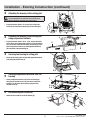
2
Attaching fan housing to the ceiling joist
CAUTION: Allow for the thickness of ceiling board used
in your application. Do not ush mount to the joist.
Flange should be ush with the ceiling board.
If spacing between joists is 12 in. apart, use 4 long wood
screws (C) to attach the fan housing (A) to the ceiling joist
3
Attaching fan housing to the ceiling joist
using suspension brackets
If spacing between joists is 16 in. - 24 in., and you have attic
access above, insert suspension bracket I (F) into the bracket
cover on the duct connector side of the fan housing (A). Then,
attach suspension bracket II (G) and suspension bracket III
(H) to the back of the fan housing (A).
4
Securing fan housing to ceiling joist
Secure the fan housing (A) to the joist with suspension brackets
(G, H) using long wood screws (C).
5
Securing suspensions brackets onto fan
housing
Secure suspension brackets (G, H) to the fan housing (A)
using the two machine screws (D) and secure suspension
bracket (F) to the other side of housing using the short
machine screw (E).
6
Reconnecting duct connector
Attach the duct connector to the fan housing (A).
A
C
A
F
G
H
C
G, H
A
A
A
D
G, H
0.24"
E
F

10
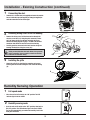
7
Connecting the duct
Connect a 6 in. circular duct (not supplied) and vent to the outside.
Secure it with duct tape (not supplied) or clamp (not supplied) to
make the connection secure and air tight.
8
Removing wiring cover on the fan housing
Quick
Connector
Product
Wires
House
Wires
Remove the wiring cover. Pull the house wires through the
wire box cover hole (8.1). Using the quick connector, secure
120 V AC house wiring from the wall switch to the fan as
shown in the wiring diagram on page 3. 14 AWG is the smallest
conductor that should be used for branch circuit wiring.
Carefully push the connected wires back into the wiring box
housing. Reattach the wiring box cover (8.1).
CAUTION: If the electrical wires do not match the colors
listed, you must determine what each house wire represents
before connecting. You may need to consult an electrical
contractor to determine safely.
9
Installing the grille
Attach the grille (B) by pinching the mounting springs and
inserting into the narrow rectangular slots in the fan housing
(A).
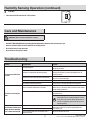
Humidity Sensing Operation
1
Full speed mode
Move the wall on/off switch to the “ON” position. The LED
indicator light in the fan is RED.
2
Humidity sensing mode
Cycle the wall on/off switch to the “OFF” position, then back to
the “ON” position. The LED Indicator light in the fan is GREEN.
The fan will automatically go on when the humidity level in the
room goes above 60%
Installation - Existing Construction (continued)
8.1
B
A

11
HAMPTONBAY.COM
Please contact 1-855-HD-HAMPTON for further assistance.
WARNING: Disconnect power supply before servicing.
See SAFETY INFORMATION before proceeding. Routine maintenance should be done at least once a year.
Never use solvents, thinner or harsh chemicals for cleaning the fan.
Do not allow water to enter the motor.
Do not immerse metal parts in water.
Care and Maintenance
Troubleshooting
Problem Possible Cause
Solution
The fan seems louder than
it should.
The CFM is too great.
Be sure the CFM rating on the fan matches the square
footage of your room.
The damper is damaged or not working properly.
Check the damper to ensure it is opening and closing
properly. If the damper has become damaged, please call
Customer Service.
The bend in the duct is too close to the fan discharge.
Be sure you do not have any sharp bends in the duct closer
than 18 in. to the fan discharge.
The fan discharge is reduced to t a smaller duct. Use the recommended size ducting to reduce fan noise.
The fan body is not attached securely. Be sure the fan is securely attached to the ceiling joists.
The fan is not clearing the
room.
There is insufcient airow intake in the room.
Be sure a door or window is slightly ajar or opened to allow
airow. The fan is not able to draw air out of the room without
enough airow to draw from.
There is insufcient CFM. Be sure the CFM rating on the fan matches the requirements
for your room size.
NOTE: Using a tissue is not the correct method for
determining if the fan is operating properly. If the fan
clears steam from the room within approximately 15
minutes of completeing your shower, then the fan is
operating properly.
The fan keeps running even
though the house humidity
level is lower than 60% RH.
Our sensor tolerance is +/-10% RH.
Continue to let fan run since it is good to keep venting the
house and the electric bill is minimal (approximately less
than $10 per year).
Outdoor humidity is back drafting into the fan.
Built-in 10 minute delay time after humidity level is
lower than 60% RH.
Turn the fan off when not in use.
Humidity Sensing Operation (continued)
3
Fan off
Move the wall on/off switch to the “OFF” position.

Questions, problems, missing parts? Before returning to the store,
call Hampton Bay Customer Service
8 a.m. - 7 p.m., EST, Monday-Friday,
9 a.m. - 6 p.m., EST, Saturday
1-855-HD-HAMPTON
HAMPTONBAY.COM
Retain this manual for future use.

1
Núm. de artículo1002-368-503
Núm. de modelo 7136-01
GUÍA DE USO Y CUIDADO
SISTEMA DE VENTILACIÓN DETECTOR DE HUMEDAD
¿Tiene preguntas, problemas, o faltan piezas? Antes de regresar a la tienda,
llame a Servicio al Cliente de Hampton Bay
de lunes a viernes de 8 a.m. a 7 p.m., sábado de 9 a.m. a 6 p.m., hora local del Este.
1-855-HD-HAMPTON
HAMPTONBAY.COM
GRACIAS
Apreciamos la confianza que ha depositado en Hampton Bay por la compra de este sistema de ventilación de baño. Nos esforzamos por crear
continuamente productos de calidad diseñados para mejorar su hogar. Visítenos en Internet para ver nuestra línea completa de productos disponibles
para sus necesidades de mejorar su hogar. ¡Gracias por elegir a Hampton Bay!

2
Índice ............................................................................... 2
Información de seguridad.............................................. 2
Especicaciones del producto ...................................... 3
Instalación típica ............................................................ 3
Diagrama de cableado ................................................... 3
Instrucciones del conector rápido ...........................................3
Garantía ........................................................................... 4
GARANTÍA DE POR VIDA LIMITADA ..........................................4
Lo que está cubierto ...............................................................4
Pre-instalación ................................................................ 4
Planicación de la instalación ................................................. 4
Herramientas requeridas.........................................................4
Contenido del paquete ............................................................ 5
Instalación: construcción nueva ................................... 6
Instalación: construcción existente .............................. 8
Operación del sensor de humedad............................. 10
Cuidado y mantenimiento ............................................ 11
Resolución de fallas ..................................................... 11
Índice
Información de seguridad
Por favor, lea y comprenda este manual completo antes de intentar ensamblar, operar o instalar
el producto.
1. Siempre desconecte la fuente de alimentación antes de darle servicio al ventilador, motor o caja de empalmes.
2. Siga todos los códigos locales de construcción, de seguridad y eléctricos así como el NEC (Código Eléctrico Nacional) y OSHA (Ley de Salud
y Seguridad Ocupacional).
3. El suministro del servicio eléctrico debe ser de 120 voltios, 60 hertz.
4. Este producto debe conectarse apropiadamente al conductor con conexión a tierra del circuito de alimentación.
5. No doble ni retuerza los cables de energía.
6. No use este ventilador con ningún dispositivo de control de estado sólido, como un control remoto, interruptor de atenuación o ciertos
temporizadores. Los temporizadores mecánicos no son dispositivos de estado sólido.
7. No instale en un techo con aislamiento mayor de R50.
8. El conducto se debe instalar en una línea recta con dobleces mínimos.
9. El tamaño del conducto debe ser de mismo tamaño que la descarga y no debe ser reducido. La reducción del tamaño del ducto puede aumentar
el ruido del ventilador.
ADVERTENCIA: Para reducir el riesgo de incendio, choque eléctrico o lesiones a las personas, respete lo siguiente:
1. Use esta unidad en la manera prevista por el fabricante. Si tiene preguntas. Llame a Servicio al Cliente
2. Antes de darle servicio o limpiar la unidad, desconecte la energía en el panel de servicio y cierre el servicio desconectando los medios para
evitar que la energía se active accidentalmente. Cuando los medios de desconexión del servicio no se pueden cerrar, coloque con seguridad
un dispositivo de advertencia fácil de ver, como una etiqueta, sobre el panel de servicio.
3. El trabajo de instalación y el cableado eléctrico debe ser hecho por una persona calicada, de acuerdo con todos los códigos y normas aplicables,
incluyendo la construcción con clasicación ignífuga.
4. Se necesita suciente aire para una combustión apropiada y el escape de los gases a través del conducto (chimenea) del equipo que quema
combustible para evitar explosión de humo. Siga las pautas del fabricante de equipo de calefacción y las normas de seguridad como las
publicadas de la Asociación Nacional de Protección contra Incendios (NFPA), y de la Sociedad Estadounidense de Ingenieros en Calefacción,
Refrigeración y Aire Acondicionado (ASHRAE), y las autoridades del código local.
5. Cuando corte o perfore en la pared o techo, no dañe el cableado eléctrico u otros servicios ocultos.
6. Los ventiladores canalizados siempre deben ser ventilados a exteriores.
7. Si esta unidad se va a instalar sobre una tina o ducha, se debe marcar según sea apropiado para la aplicación y conectarse a un circuito de
derivación protegido GFCI (Interruptor de circuito de falla a tierra).
PRECAUCIÓN: Para uso de ventilación general solamente. No lo use para desalojar materiales y vapores peligrosos o explosivos.
PRECAUCIÓN: No para ser utilizado en área de cocina.
PRECAUCIÓN: Para reducir el riesgo de lesiones a las personas, instale el ventilador al menos a 7 pies (2.1m) sobre el piso.

3
HAMPTONBAY.COM
Póngase en contacto con el 1-855-HD-HAMPTON para asistencia adicional.
Especicaciones del producto
Instalación típica
Diagrama de cableado
ESPECIFICACIONES ESPECIFICACIONES
Flujo de aire: 140 pies
3
/min (CFM) Consumo de energía: 48 W
120 V, 60 Hz Peso: 10.78 lbs.
Diámetro del ducto: 6 pulg.
Requerimientos de dimensión de abertura del techo: 10-13/16 pulg.
(L) x 10-1/2 pulg. (Ancho) x 8-1/2 pulg. (Alto)
Salida de sonido: 1.0 Sones
El ducto de este ventilador al exterior del edicio tiene
un fuerte efecto en el ujo del aire, ruido y uso de la
energía del ventilador. Use la orientación del ducto
más corta y recta posible para un mejor desempeño,
y evite instalar el ventilador con ductos más pequeños
que los recomendados. La instalación alrededor de
los ductos puede reducir la pérdida de energía
e inhibir el crecimiento de moho. Es posible que
los ventiladores instalados con ductos existentes
no logren su ujo de aire nominal.
ADVERTENCIA: El cableado debe cumplir todos los códigos
eléctricos aplicables. Desconecte la energía antes de retirar
o instalar los conectores.
ADVERTENCIA: COBRE A COBRE SOLAMENTE. No use en cable
de aluminio.
PRECAUCIÓN: La pieza accesoria (conector rápido) debe cumplir
NOTA: El conector es reutilizable en cables sólidos del mismo calibre
o más pequeño. No reutilice el conector en cables trenzados
.
•
Pele los cables de 3/8 pulg. a 1/2 pulg.
• Sujete con firmeza el cable y empuje
el extremo pelado del cable en el
puerto abierto del conector.Use
solo un conductor por puerto.
• Verifique que el extremo pelado
de los cables esté completamente
insertos en la parte posterior
del conector.
t
NOTA: Información importante del cable. Capacidad nominal de
temperatura máxima 105°C (221°F). 600 voltios máximo para cable
de construcción y 1000 voltios máximo para cable de construcción
y 1000 voltios máximo en dispositivos de señalización e iluminación.
El rango de cable aceptable incluye: Sólido: 12-18 AWG.
Aísle adecuadamente
alrededor del ventilador
para minimizar la
pérdida y ganancia
de calor del edicio
Carcasa del
ventilador
Selle cualquier
espacio alrededor
de la carcasa
del ventilador
Tendido recto
de 2 a 3 pies
antes del codo
Tapa de
pared (con
amortiguador
incorporado)
Tapa de techo
(con amortiguador
incorporado)
Terminación
de masilla
al ducto
O
Las piezas cortas de
ducto exible ayudan
a alinear y absorber
el sonido
Cables
de la
casa
Conector
rápido
Cables del
producto
Condensador
para una vida
más larga
del motor
CARCASA DEL VENTILADOR
Cable negro
Cable blanco
al interruptor
al neutro
Cable verde
a tierra
Caja de empalmes
Sensor de
humedad
a
Interruptor terminal
automático

4
GARANTÍA DE POR VIDA LIMITADA
LO QUE ESTÁ CUBIERTO
Si este producto falla debido a un defecto en materiales o mano de obra en cualquier momento durante los primeros CINCO años de propiedad, el fabricante
lo reemplazará libre de cargos. Esta garantía no cubre productos que han sido maltratados, alterados, dañados, mal empleados, cortados o deteriorados.
Esta garantía no cubre el uso en aplicaciones comerciales. Use solo piezas de repuesto de reparación con garantía genuina suministrados por el fabricante
para reparar este ventilador. El usode piezas de reparación no genuinas anulará su garantía. El fabricante RENUNCIA a otras garantías implícitas o expresas
incluyendo todas las garantías de comercialización o idoneidad para un propósito particular. Debido a que algunos estados no permiten exclusiones
o limitaciones de una garantía implícita, es posible que las exclusiones y limitaciones antes mencionadas no apliquen. Esta garantía le otorga derechos
legales especícos y también puede tener otros derechos que varían de un estado a otro.
Esta garantía está limitada al reemplazo de piezas defectuosas solamente. Los cargos por mano de obra y/o daños generados durante la instalación,
reparación, reemplazo así como también daños incidentales o consecuentes relacionados con lo anterior están excluidos. Cualquier daño a este
producto que resulte de negligencia, mal uso, accidente, instalación inadecuada u otro uso que no sea el previsto ANULARÁN ESTA GARANTÍA.
Los costos de envío por devolución de producto como parte de un reclamo sobre la garantía deben ser pagados por el cliente.
Póngase en contacto con el Equipo de Servicio al Cliente llamando al 1-855-HD-HAMPTON o visite www.HAMPTONBAY.com.
Garantía
Pre-instalación
PLANIFICACIÓN DE LA INSTALACIÓN
Antes de comenzar a ensamblar este producto, asegúrese de que todas las piezas estén presentes. Compare las piezas con la lista de contenido del
paquete y herraje incluido. Si hace falta alguna pieza o se encuentra dañada, no intente ensamblar el producto.
ADVERTENCIA: Desconecte la electricidad en la caja del
disyuntor antes de comenzar la instalación.
Retire con cuidado la unidad de la caja.
Revise el área sobre el lugar de la instalación para asegurarse de que el cableado se pueda tender al lugar planicado y que el conducto se pueda
tender y el área sea suciente para una ventilación adecuada.
Inspeccione el conducto y el cableado antes de proceder con la instalación.
Antes de la instalación, proporcione acceso a inspección y mantenimiento futuros en un lugar que no interera con el trabajo de instalación.
Es posible que necesite la ayuda de una segunda persona para instalar este ventilador; una persona en el lado del ático y otra en el lado de la habitación.
NOTA: La instalación puede variar dependiendo de cómo se instaló
el ventilador de baño anterior. No todos los suministros necesarios
para la instalación de su ventilador de baño están incluidos. Sin
embargo, la mayoría están disponibles en su tienda local de
mejorar su hogar o herrajes.
HERRAMIENTAS REQUERIDAS (no incluidas)
Martillo
de garra
Brocas
Destornillador
de punta plana
Cinta
de ducto
Destornillador
Phillips
Navaja
multiusos
Taladro
eléctrico

5
HAMPTONBAY.COM
Póngase en contacto con el 1-855-HD-HAMPTON para asistencia adicional.
Pre-instalación (continuación)
CONTENIDO DEL PAQUETE
A
B
Pieza Descripción Cantidad
A Carcasa del ventilador 1
B Rejilla 1
C Tornillos largos para madera (M4x30mm) 8
D Tornillos de máquina (M4x12mm) 2
E Corto tornillos de máquina (M4x10mm) 1
F Soporte de suspensión I 1
G Soporte de suspensión II 1
H Soporte de suspensión III 1
F
G
H
C
D
E

6
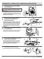
Instalación: construcción nueva
PRECAUCIÓN: Asegúrese de que la energía esté
desconectada en el panel de servicio antes de
comenzar la instalación.
NOTA: Montaje en techo únicamente.
1
Instalación de la carcasa del ventilador
en la viga del techo
PRECAUCIÓN: Tenga en cuenta el espesor de la tabla
del techo utilizada en su aplicación. No monte al
ras en la viga. La brida debe estar al ras con la
tabla del techo.
Si el espacio de separación entre las vigas es de 12 pulg., use
4 tornillos para madera largos (C) para instalar la carcasa del
ventilador (A) en la viga del techo
2
Instale la carcasa del ventilador en la
viga del techo utilizando los soportes
de suspensión
Si el espacio entre las vigas es de 16 pulg. - 24 pulg., inserte
el soporte de suspensión I (F) en la cubierta del soporte en el
lado del conector del ducto de la carcasa del ventilador (A).
Luego, instale el soporte de suspensión II (G) y el soporte
de suspensión II (H) en la parte trasera de la carcasa del
ventilador (A).
3
Cómo asegurar la carcasa del ventilador
en la viga del techo
Asegura la carcasa del ventilador (A) en la viga con los soportes
de suspensión (G, H) usando tornillos para madera largos (C).
A
A
C
F
G
A
C
G, H
H
Viga
0.24
Tabla del
techo

7
HAMPTONBAY.COM
Póngase en contacto con el 1-855-HD-HAMPTON para asistencia adicional.
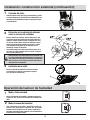
Instalación: construcción nueva (continuación)
4
Cómo asegurar los soportes de suspensión
sobre la carcasa del ventilador
Asegure los soportes de suspensión (G, H) a la carcasa del
a (A) con los dos tornillos de la máquina (D) y asegure el
soporte de la suspensión (F) al otro lado de la carcasa utili-
zando el cortocircuito tornillo de la máquina (E).
5
Extracción de la cubierta del cableado
sobre la carcasa del ventilador.
Retire la cubierta del cableado. Hale los cables de la casa
a través del agujero de la cubierta de la caja de cables (5.1).
Usando el conector rápido, asegure el cableado de la casa
de 120 V AC del interruptor de pared al ventilador como se
muestra en el diagrama de cableado en la página 3. 14 AWG
es el conductor más pequeño que se debe usar para el
cableado de circuito de derivación.
Con cuidado, empuje los cables conectados de nuevo en la
carcasa de la caja de cableado. Vuelva a colocar la cubierta
de la caja del cableado (5.1).
PRECAUCIÓN: Si los cables eléctricos no coinciden con
los colores enumerados, debe determinar lo que representa
cada cable de la casa antes de conectarlos. Es posible que
deba consultar con un contratista eléctrico para hacer la
determinación con seguridad.
6
Conexión del ducto
Conecte un ducto circular de 6 pulg. (no suministrado) y ventile
al exterior. Asegúrelo con cinta de ducto (no suministrada)
o una abrazadera (no suministrada) para que la conexión
sea segura y a prueba de aire.
Encienda la fuente de alimentación. Revise el ventilador en
busca de sonido o vibración anormales.
7
Instalación de la rejilla
Instale la rejilla (B) apretando los resortes de montaje
e insertando en las ranuras rectangulares angostas en
la carcasa del ventilador (A).
A
B
DF
E
G, H
5.1
A

8
Instalación: construcción existente
1
Retire el ventilador existente.
PRECAUCIÓN: Tenga en cuenta el espesor de la tabla
del techo utilizada en su aplicación. No monte al
ras en la viga. La brida debe estar al ras con la
tabla del techo.
Retire el ventilador viejo del techo.
2
Mida la abertura del techo
1
1
1
1
0
9
8
7
6
5
4
Mida la abertura para asegurarse de que sea sucientemente
larga para que se acomode al cuerpo del ventilador nuevo (A)
(10.25 pulg. x 10.25 pulg.).
3
Alargue la abertura (opcional)
10.25"
10.25"
Si este ventilador no está reemplazando a un ventilador viejo,
asegúrese de cortar una abertura de 10.25 pulg. x 10.25 pulg.
para el cuerpo del ventilador (A).
ASEGÚRESE DE QUE UN BORDE DE LA ABERTURA ESTÉ A RAS
CON LA VIGA PARA LA INSTALACIÓN DESDE ABAJO .
LA INSTALACIÓN DESDE ABAJO CON SOPORTES DE SUSPENSIÓN (ACCESIBLE AL ÁTICO) ÚNICAMENTE SI NO ES POSIBLE INSTALAR DIRECTAMENTE
A LA VIGA.
1
Extracción del conector del ducto
Retire el conector del ducto de la carcasa del ventilador.
Inserte la carcasa del ventilador en el corte de la abertura
en la pared seca.
Viga
0.24
Tabla del
techo

9
HAMPTONBAY.COM
Póngase en contacto con el 1-855-HD-HAMPTON para asistencia adicional.
Instalación: construcción existente (continuación)
2
Instalación de la carcasa del ventilador
en la viga del techo
PRECAUCIÓN: Tenga en cuenta el espesor de la tabla
del techo utilizada en su aplicación. No monte al ras
en la viga. La brida debe estar al ras con la tabla
del techo.
Si el espacio de separación entre las vigas es de 12 pulg., use
4 tornillos para madera largos (C) para instalar la carcasa del
ventilador (A) en la viga del techo
3
Instalación de la carcasa del ventilador
en la viga del techo utilizando los
soportes de suspensión
Si el espacio entre las vigas es de 16 pulg. - 24 pulg., inserte
el soporte de suspensión I (F) en la cubierta del soporte en el
lado del conector del ducto de la carcasa del ventilador (A).
Luego, instale el soporte de suspensión II (G) y el soporte
de suspensión II (H) en la parte trasera de la carcasa del
ventilador (A).
4
Cómo asegurar la carcasa del ventilador
en la viga del techo
Asegura la carcasa del ventilador (A) en la viga con los soportes
de suspensión (G, H) usando tornillos para madera largos (C).
5
Cómo asegurar los soportes de suspensión
sobre la carcasa del ventilador
Asegure los soportes de suspensión (G, H) a la carcasa del
a (A) con los dos tornillos de la máquina (D) y asegure el
soporte de la suspensión (F) al otro lado de la carcasa utili-
zando el cortocircuito tornillo de la máquina (E).
6
Reconexión del conector del ducto
Instale el conector del ducto en la carcasa del ventilador (A).
A
C
A
F
G
H
C
G, H
A
A
D
G, H
Viga
0.24
Tabla del
techo
F
E

10
7
Conexión del ducto
Conecte un ducto circular de 6 pulg. (no suministrado) y ventile
al exterior. Asegúrelo con cinta de ducto (no suministrada) o una
abrazadera (no suministrada) para que la conexión sea segura
y a prueba de aire.
8
Extracción de la cubierta del cableado
sobre la carcasa del ventilador.
Retire la cubierta del cableado. Hale los cables de la casa
a través del agujero de la cubierta de la caja de cables (8.1).
Usando el conector rápido, asegure el cableado de la casa
de 120 V AC del interruptor de pared al ventilador como se
muestra en el diagrama de cableado en la página 3. 14 AWG
es el conductor más pequeño que se debe usar para el
cableado de circuito de derivación.
Con cuidado, empuje los cables conectados de nuevo en la
carcasa de la caja de cableado. Vuelva a colocar la cubierta
de la caja del cableado (8.1).
PRECAUCIÓN: Si los cables eléctricos no coinciden con
los colores enumerados, debe determinar lo que representa
cada cable de la casa antes de conectarlos. Es posible que
deba consultar con un contratista eléctrico para hacer la
determinación con seguridad.
9
Instalación de la rejilla
Instale la rejilla (B) apretando los resortes de montaje
e insertando en las ranuras rectangulares angostas
en la carcasa del ventilador (A).
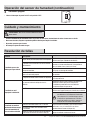
Operación del sensor de humedad
1
Modo a toda velocidad
Mueva el interruptor de encendido / apagado de la pared a
la posición "ON". El LED la luz indicadora del ventilador está
ROJA.
2
Modo de sensor de humedad
Cicle el interruptor de encendido / apagado de la pared a la
posición "OFF", luego vuelva a la posición "ON". El indicador
luminoso LED del ventilador está en verde. El ventilador se
encenderá automáticamente cuando el nivel de humedad en
la habitación sea superior al 60%
Instalación: construcción existente (continuación)
8.1
B
A

11
ADVERTENCIA: Desconecte la fuente de alimentación antes
de dar servicio.
Consulte INFORMACIÓN DE SEGURIDAD antes de proceder. Se debe hacer mantenimiento de rutina al menos una vez al año.
Nunca use solventes, diluyentes o productos químicos fuertes para limpiar el ventilador.
No permita que entre agua al motor.
No sumerja las piezas de metal en agua.
Cuidado y mantenimiento
Resolución de fallas
Operación del sensor de humedad (continuación)
3
Ventilador apagado
Mueva el interruptor de pared "on/off" en la posición “OFF”.
Problema Causa posible
Solución
El ventilador parece más
ruidoso que lo que debería.
Los pies cúbicos por minuto (CFM) son demasiado grandes.
Asegúrese de que la capacidad nominal de CFM en el ventilador
coincida con los pies cuadrados de suhabitación.
El regulador de tiro está dañado o no está funcionando
adecuadamente.
Revise el regulador de tiro para asegurarse de que esté
abriendo y cerrando adecuadamente. Si el regulador de
tiro se ha dañado, llame a Servicio al Cliente.
El doblez en el ducto está demasiado cerca de la
descarga del ventilador.
Asegúrese de no tener dobleces losos en el ducto más cerca
de 18 pulg. a la descarga del ventilador.
La descarga del ventilador está reducida para que se
ajuste en un ducto más pequeño.
Use el ducto del tamaño recomendado para reducir el ruido
del ventilador.
El cuerpo del ventilador no está instalado con seguridad.
Asegúrese de que el ventilador esté instalado con seguridad
en las vigas del techo.
El ventilador no está
despejando la habitación.
Hay consumo insuciente de ujo de aire en la
habitación.
Asegúrese de que una puerta o ventana esté ligeramente
entreabierta o abierta para permitir el ujo de aire.
El ventilador no puede extraer aire de la habitación
sin suciente ujo de aire que extraer.
Los CFM no son sucientes.
Asegúrese de que la capacidad nominal de CFM en el ventilador
coincida con los requerimientos para el tamaño de su habitación.
NOTA: El uso de un pañuelo no es el método correcto
para determinar si el ventilador está funcionando
adecuadamente. Si el ventilador despeja vapor de
la habitación en aproximadamente 15 minutos
después de terminar con su ducha, entonces el
ventilador está funcionando adecuadamente.
El ventilador se mantiene
funcionando incluso aunque
el nivel de humedad de la
casa sea inferior a 60% RH.
La tolerancia de nuestro sensor es de +/-10% RH.
Deje funcionando el ventilador ya que es bueno mantener
ventilando la casa y la factura eléctrica es mínima
(aproximadamente menos de $10 por año)
La humedad del exterior está entrando de nuevo
en el ventilador.
Incorpore un tiempo de retraso de 10 minutos después
de que el nivel de humedad sea inferior a 60% RH.
Apague el ventilador cuando no esté en uso.
HAMPTONBAY.COM
Póngase en contacto con el 1-855-HD-HAMPTON para asistencia adicional.

¿Tiene preguntas, problemas, o faltan piezas? Antes de regresar a la tienda,
llame a Servicio al Cliente de Hampton Bay
de lunes a viernes de 8 a.m. a 7 p.m.,
sábado de 9 a.m. a 6 p.m., hora local del Este.
1-855-HD-HAMPTON
HAMPTONBAY.COM
Conserve este manual para uso futuro.
-
 1
1
-
 2
2
-
 3
3
-
 4
4
-
 5
5
-
 6
6
-
 7
7
-
 8
8
-
 9
9
-
 10
10
-
 11
11
-
 12
12
-
 13
13
-
 14
14
-
 15
15
-
 16
16
-
 17
17
-
 18
18
-
 19
19
-
 20
20
-
 21
21
-
 22
22
-
 23
23
-
 24
24


Hampton Bay 7136-01 Guía de instalación
- Tipo
- Guía de instalación
- Este manual también es adecuado para
En otros idiomas
Documentos relacionados
-
 Hampton Bay 7107-03 Guía de instalación
-
Hampton Bay BPT18-34A-2 Guía de instalación
-
 Hampton Bay BPT12-13D Manual de usuario
-
 Hampton Bay 52869 Guía de instalación
-
Hampton Bay 46008 Guía de instalación
-
 Hampton Bay 57289 Instrucciones de operación
-
 Hampton Bay 51548 Guía de instalación
-
 Hampton Bay 51538 Guía de instalación
-
 Hampton Bay 87653 Guía de instalación
-
 Hampton Bay 51218 Guía de instalación


