Snapper 7800179 El manual del propietario
- Categoría
- Cortadoras de césped
- Tipo
- El manual del propietario
Este manual también es adecuado para

SafetyInstructions& Operator'sManualfor
\
21" VARIABLESPEED
REARDISCHARGE
WALKBEHIND
MOWERS
Models
SPV21675(7800179)
SPV21675E(7800417)
NSPV21675(7800421)
NSPV21675E(7800422)
NOTE:Specificationsarecorrectattime ofprintingandaresubjecttochangewithoutnotice.
* Actualsustainedenginepowerwill likelybelowerdueto operatinglimitationsandenvironmentalfactors. Pleasereferto 'EnginePowerRatingInformation'for further
details.
$1tlAPPER.coo°oo_,,o,..,o_,,o._.,. Manual No. 7103136 (Rev.'-', 12/19/2008)

ThankYou for purchasingthis quality-built Snappermower.We're pleasedthat you placedyour
confidencein the Snapperbrand.Whenoperatedand maintainedaccordingto the instructions in this
manual,your Snappermowerwill provide manyyearsof dependableservice.
This manual contains safety information to make you aware of the hazards and risks associated with the
machine and how to avoid them. This machine is designed and intended only for finish cutting of
established lawns and is not intended for any other purpose. It is important that you read and understand
these instructions thoroughly before attempting to start or operate this equipment. Save these
instructions for future reference.
PRODUCT REGISTRATION
IMPORTANT:KEEPTHISINFORMATIONFORYOURPERSONALRECORDS
(Completethe following information on your Snapperpurchase)
Dateof Purchase
Retailer
Retailer's PhoneNumber
Equipment
Model Number
Serial Number
Engine
Model .Type. Trim
It is very importantthat you registeryour purchasewith Snapperto ensurewarrantycoverage.Please
mail your product registration cardto:
Snapperat P.O.Box1379, McDonough,Georgia30253.
You cancontact us at ourwebsite (www.snapper.com),or if you would like to speakwith a Customer
ServiceRepresentative,call us atthe SnapperCustomerRelationsCenterat 1-800-317-7833. Forfaster
servicepleasehaveyour SerialNumberand Model Numberavailable.
SNAPPERis a trademark of
Briggs & Stratton Yard Power Products Group, LLC
Jefferson, Wl, USA.
Briggs & Stratton Yard Power Products Group
Copyright © 2008, Briggs & Stratton Corporation
Milwaukee, Wl, USA. All Rights Reserved.

Tableof Contents
OperatorSafety ........................................................ 4
Important OperatorSafety Instructions .................................. 4
Featuresand Controls ................................................... 6
Operation ............................................................. 7
Pre-Start Checklist .................................................. 7
Starting & Stopping Engine& Blade ..................................... 7
Propelling Mower ................................................... 8
HandleHeight Adjustment ............................................ 8
Cutting Height Adjustment ............................................ 9
Recycling Operation ................................................. 9
Installing the DischargeDeflector ...................................... 10
Removingthe Recycling Plug ......................................... 10
Installing the Grass Bag ............................................. 10
Maintenance .......................................................... 11
ChangeEngine Oil .................................................. 11
CheckMower Blade ................................................ 11
CheckEngineDrive Belt ............................................. 11
Service - Periodic .................................................. 11
Engine ........................................................... 11
Air Filter ......................................................... 11
Engine Oil ........................................................ 11
WheelDrive Components ............................................ 12
Storage Procedure ................................................. 12
Mower Blade Replacement ........................................... 13
BladeSharpening .................................................. 13
WheelDrive Control Adjustment ....................................... 14
Belt Service ....................................................... 15
Engine DriveBelt Replacement ........................................ 15
Battery Service .................................................... 16
RearCover Removal& Installation ..................................... 17
Service Schedule................................................... 18
Troubleshooting ....................................................... 19
Warranty ............................................................ 20
Slope Guide .......................................................... 21
(:3
{3
"'1"1
:3
¢z
0
:3
(:3
0
:3
:3
:3
:3
._......J
--I
0
€3"
C_
0
{3
:3
WARNING
Batteryposts, terminals and relatedaccessoriescontain
lead andlead compounds, chemicals knownto the State of
California to causecancer andbirth defectsor other
reproductiveharm. Wash handsafter handling.
WARNING
Engineexhaust,some of its constituents, and certain
vehicle components containor emit chemicals known to
the State of Californiato causecancer or other reproductive
harm.
:3

O
¢Z
O
A
IMPORTANTOPERATORSAFETYINSTRUCTIONS
WARNING:This powerful cutting machine is capableof amputating handsand feet and canthrow objects
that can cause injury and damage!Failureto comply with the following SAFETYinstructions could result in
serious injury or deathto the operator or other persons.The owner of the machine must understand these
instructions and must allow only persons who understandthese instructions to operate machine.Each
personoperating the machine must be of sound mind and body and must not be under the influenceof any
substance,which might impair vision, dexterity or judgment. If you haveany questions pertaining to your
machinewhich your dealer cannotanswer to your satisfaction, call or write the Customer Service
Departmentat SNAPPER,IVIcDonough,Georgia30253. Phone:(1-800-317-7833).
PROTECTIONFORCHILDREN
Tragic accidentscanoccur if the operator is not alert to the
presenceof children. Children are often attracted to the
machine andthe mowing activity. Neverassumethat
children will remain whereyou last saw them.
1. KEEPchildren out of the mowing area and under the
watchful careof aresponsible adult other than the operator.
2. DONOTallow children in yard when machine is operated
andturn machine OFFif anyoneenters the area.
3. DONOTallow pre-teenagechildren to operate machine.
4. ALLOW only responsible adults & teenagerswith mature
judgment under closeadult supervision to operate machine.
5. DONOTpull mower backwards unless absolutely
necessary.LOOKand SEEbehind and down for children,
pets andhazards beforeand while backing.
6. USEEXTRACAREwhen approaching blind corners,
shrubs, trees, or other objects that may obscure vision.
SLOPE OPERATION
1. Slopesare amajor factor relatedto slip andfall
accidents,which can result in severeinjury. All slopes
require extracaution. If you feel uneasyon a slope, DONOT
mow it.
2. Mow across slopes, neverup-and-down. Exercise
extremeCAUTIONwhen changing directions on slopes. DO
NOTmow steep slopesor other areaswhere stability or
traction is in doubt. Referto the Slope Guideat the back of
this manual.
3. Useextra carewith grass catchers or other attachments;
these affect the handlingand the stability of the machine.
PREPARATION
1. Read,understand, andfollow instructions andwarnings
in this manualand on the mower, engineand attachments.
Knowthe controls and the proper useof the mower before
starting.
2. Only mature, responsible personsshall operatethe
machine andonly after proper instruction.
3. Data indicatesthat operators age60 and above,are
involved in a large percentageof mower-related injuries.
Theseoperators should evaluatetheir ability to operatethe
mower safely enoughto protect themselvesand others
from serious injury.
4. Handlefuel with extra care. Fuelsareflammable and
vapors are explosive.Useonly an approvedfuel container.
DONOTremovefuel capor add fuel with engine running.
PREPARATION
(ContinuedFromPrevious Column)
Add fuel outdoors only with engine stoppedand cool. Clean
spilled fuel and oil from machine. DONOTsmoke.
5. Checkthe areato be mowed and removeall objects such
as toys, wire, rocks, limbs and other objects that could
cause injury if thrown by bladeor interfere with mowing.
Also notethe location of holes, stumps, and other possible
hazards.
6. Keeppeopleand pets out of the mowing area.
Immediately,STOPBlade,Stop engine and Stop mower if
anyone enters the area.
7. Checkshields, deflectors, switches, blade controls and
other safety devicesfrequently for proper operation and
location.
8. Make sureall safety decalsare clearly legible. Replaceif
damaged.
9. Protectyourself when mowing and wear safetyglasses,
long pants andsubstantial footwear. DONOTmow
barefootedor with sandals.
10. Know how to STOPbladeand engine quickly in
preparationfor emergencies.
11. Use extracarewhen loading or unloading the machine
into a trailer or truck.
12. Checkgrass catchercomponents frequently for signs of
wear or deterioration and replaceas neededto prevent
injury from thrown objects going through weak or torn
spots.
SAFEHANDLINGOFGASOLINE
Toavoid personal injury or property damage, useextreme
care in handling gasoline. Gasolineis extremely flammable
and the vapors areexplosive.
1. Extinguishall cigarettes, cigars, pipes and other sources
of ignition.
2. Use only anapprovedfuel container.
3. DONOTremovefuel cap or add fuel with the engine
running. Allow the engineto cool before refueling.
4. DONOTrefuelthe machine indoors.
5. DONOTstore the machineor fuel containerinside where
there is an openflame, spark or pilot light such as on a
water heateror other appliances.
6. DONOTfill fuel containers inside a vehicleor on a
truck or trailer bedwith a plastic liner.Always placethe
containers on the ground awayfrom the vehicle before
filling.
4 www.snapper.corn

IMPORTANTOPERATORSAFETYINSTRUCTIONS(Continued)
SAFEHANDLING OFGASOLINE
(ContinuedFrom PreviousPage)
7. Removegas-poweredequipment from the vehicle or
trailer and refuelit on the ground. If this is not possible,
then refuelequipment using a portablecontainer, rather
than a gasolinedispenser nozzle.
8. DONOTstart gas poweredequipment in enclosed
vehicles or trailers.
9. Keepthe nozzlein contact with the rim of the fuel tank or
container openingat all times until fueling is complete. DO
NOTusea nozzle lock-opendevice
10. If fuel is spilled on clothing, change clothing
immediately.
11. DONOToverfill a fuel tank. Replacefuel cap and tighten
securely.
OPERATION
1. DONOTput handsor feet near or under rotating parts.
Keepclearof dischargeareawhile engine is running.
2. STOPenginewhen crossing gravel drives, walks, or
roads, andunder anyconditions where thrown objects
might be a hazard.
3. Mow only in daylight or good artificial light.
4. DONOToperatemower while under the influence of
alcohol or drugs.
5.After striking aforeign object or if mower vibrates
abnormally,STOPthe engine,disconnect and securespark
plug wire. Inspect the mower for anydamageand repair the
damagebeforestarting.
6. DONOTmow near drop offs, ditches or embankments.
Operatorcould lose footing or balance.
7. STAYALERTfor holes and other hidden hazards.Tall
grass can hideobstacles. Keepawayfrom ditches,
washouts, culverts, fencesand protruding objects.
8. DONOTmow on wet grass. Always be sure of your
footing. Keepa firm hold on the handleand walk, neverrun.
Slipping could cause injury.
9.ALWAYSstay behind handlewhen engine (motor) is
running.
10. DONOTleavethe machinewith the engine running.
STOPBLADEand STOPENGINEbeforeleavingthe
operators position for any reason.
11. Beforecleaning, repairing or inspecting make certain
engine,blade andall moving parts haveSTOPPED.
Disconnectand securespark plug wire awayfrom plug to
prevent accidentalstarting.
12. STOPengineandwait until the bladecomes to
completeSTOPbeforeremoving grass bag and/or clearing
grass.
13. DONOToperatemower without the entire grass
catcher,or guards in placedischarge guard, rearguard or
other safety devicesin placeand working. DONOTpoint
discharge at people,passing cars, windows or doors.
OPERATION
(ContinuedFromPrevious Column)
14. DONOTdischarge material against awall or
obstruction. Material may ricochet back towards the
operator.
15. Slow down beforeturning.
16. Watchout for traffic when near or crossing roadways.
17. DONOToperateengine in enclosedareas. Engine
exhaust gasescontain carbon monoxide, adeadly poison.
18. Onlyuse accessoriesapprovedby the manufacturer.
See manufacturer'sinstructions for proper operation and
installation of accessories.
MAINTENANCE AND STORAGE
1. DONOTstore mower or fuel container inside where
fumes may reachan open flame, sparkor pilot light such as
in awater heater,furnace, clothes dryer or other gas
appliance. Allow engineto cool before storing machine in
an enclosure.Store fuel container out of reachof children
in awell ventilated, unoccupiedbuilding.
2. Keepmower and enginefree of grass, leavesor excess
greaseto reducefire hazardand engine overheating.
3. Whendraining fuel tank, drain fuel into an approved
container outdoors and away from open flame.
4. Keepall bolts, especially bladebolts, nuts and screws
properly tight. Checkthat all cotter pins are in proper
position.
5. Alwaysprovide adequateventilation when running
engine. Engineexhaust gasescontain carbon monoxide, a
deadly poison.
6. Serviceengine and makeadjustments only when engine
is stopped. Removedspark plug wire from spark plug and
secure wire awayfrom spark plug to prevent accidental
starting.
7. DONOTchangeengine governor speedsettings or
overspeed engine.
8. Checkgrass bag assembly frequently for wear or
deterioration to avoidthrown objects and exposureto
moving parts. Replacewith new bag if loose seamsor tears
are evident. Replaceslider or bag adapterif brokenor
cracked.
9. Mower bladesare sharp andcan cut. Wrap the bladesor
wear heavy leathergloves and useCAUTIONwhen handling
them.
10. DONOTtest for spark by grounding spark plug next to
spark plug hole; spark plug could ignite gas exiting engine.
11. Havemachineserviced by an authorized SNAPPER
dealer at leastonce ayear and havethe dealerinstall any
newsafety devices.
12. Use only genuineSNAPPERreplacementparts to
assure that original standards are maintained.
O
O

IMPORTANT
The figures and illustrations in this manualare provided
for referenceonly and may differ from your specific model,
Contactyour Snapperdealer if you havequestions.
0
0
¢.3
//_,.,,_o.,-_
FeaturesandControls
A. Oil Fill Capand Dipstick
B. FuelFillerCap
C. Recycling Cover
D. Battery Box
E. Height Adjustment Lever
F.
G.
H.
I,
J.
BladeControl
RopeStart Handle
Drive WheelControl
RearDischargeDoor
Grass Bag
6 www.snapper.corn

Pre-StartCheckList
Make the following checksand perform the service required
before eachstart-up.
1. Checkthe guards,deflectors, grass bag,and coversto
make sure allare in placeand securelytightened.
2. Checkthe bladecontrol (A, Figure1) and wheel drive
control (B) to insure they work freely.
StartingandOperation
Engineand Blade
1. Pull the blade control (A, Figure3) againstthe handle.
2. Start the mower:
ManualStart Models: Pull the rope start handle (B)
to crank the engine.
ElectricStart Models: Insert the key(C) into the
ignition switch (D), located onthe right side of the
handle abovethe rope guide. Turnthe keyto crank
the engine.
3. After the enginestarts, allow a brief warm-up until the
engine runs smooth before beginning mower operation.
NOTE.Tostop the engine (and blade), releasethe blade
control.
Figure 1:Mower controls
3. Checkthe cutting height. Adjust to the desiredheight.
Refer to the Section 'Cutting Height Adjustment'.
4. Checkthe engineoil and add oil as neededto bringthe
level up to the full mark (A, Figure2). Referto the
Engine Owner'sManualfor oil specifications.
I
Figure2: Checkingengine oil
5. Add fuel to the tank after pushing the mower outside
wherefumes can safelydissipate. Fill the tank to 1-1/2
inches belowthe top of the filler neck (to allow for fuel
expansion). Makesure the cap is tightened afterfueling.
Refer to the EngineOwners Manualfor fuel
specifications.
6. Cleanthe exterior surfaces of the cutting deckand
engine of any accumulation of spilled fuel, dirt, grass,
oil, etc. Keepthe engineair intakescreenand cooling
fins clear at all times.
Figure3: Starting the mower
(:3
0

O
O
StartingandOperation(Continued)
Propellingthe Mower
1. Start the engine.Referto the Section entitled "Starting
and Operation- Engine and Blade".
2. Begin squeezingthe wheel drive control (A, Figure4)
back toward the handleto engagethe wheel drive and
propel the mower forward. Forward speedcan be
increased by squeezingthe wheeldrive control further
back toward the handle.
®
Figure4: Wheeldrive control
(Components removedfor clarity)
Stopping
1. Stop forward motion of the mower by releasingthe
wheeldrive control.
2. Stop the engine and blade by releasingthe blade
control.
HandleHeightAdjustment
Theheight of the mower handle can be adjustedasfollows:
1. Turnthe two locking cams(A, Figure5) a quarter-turn to
unlock the handle assembly(B).
2. Align the handle assemblywith one of the three handle
height adjustment holes (C) in the mounting brackets.
3. Returnthe lockingcams to their original position to lock
the handle.
Figure5: Adjusting the handleheight
WARNING
DONOTattempt anymaintenance, adjustmentsor service
with engine and blade running. STOPengineand blade.
Disconnectspark plug wire and secureaway from spark
plug. Engineandcomponents are HOT.Avoid serious
burns, allow sufficient time for all components to cool.
8 www.snapper.com

WARNING
DONOTattempt any maintenance,adjustments or service
with engine and blade running. STOPengineand blade.
Disconnectspark plug wire and secureaway from spark
plug. Engineandcomponents are HOT.Avoid serious
burns, allow sufficient time for all components to cool.
CuttingHeightAdjustment
1. Pull the height adjusting lever(A, Figure 6) outward, and
move to the desired cutting height. Thehighest cutting
position is Notch 9 (B;also see Figure7). The lowest
cutting position is Notch 1 (C).
Note: The/ever wi// set aftwhee/sto the same cutting height.
WARNING
Stop engineand mower blade by releasingthe blade
control before adjusting cutting height.
1.50 in _ 4.00 in
Figure7: Cutting height settings (approximate)
RecyclingOperation
Note:Forbest recycling results, cut up to a maximum of 1/3
of grass blade length and recycleONLYwhen grass is dry.
1. Setthe height adjustment leverin the highest cutting
position (Notch 9). Referto the Section entitled "Cutting
HeightAdjustment".
2. Proceedmowing slowly. If the grass is very dense,
lower the height adjustment lever onenotch lower to
improve recycling performance.
InstallingtheDischargeDeflector
1. Raisethe recycling cover (A, Figure8).
Important. The recyclingcover should remainon the
machine at alltimes. Donot remove.
(:3
0
Figure6:Adjusting cutting height
Figure 8: Installing the discharge deflector
2. Install the deflector (B) to the deck underthe recycling
cover,making surethat:
Thetabs (C) hook under the pivot rod (D).
Thelocking tab on the deck (A, Figure9) goes
through the slot in the deflector (B).
3. Lowerthe recycling cover againstthe deflector.

WARNING
DONOTattempt any maintenance,adjustments or service
with engine and blade running. STOPengineand blade.
Disconnectspark plug wire and secureaway from spark
plug. Engineandcomponents are HOT.Avoid serious
burns, allow sufficient time for all components to cool.
Installingthe GrassBag
1. Raisethe rear discharge door (A, Figure11).
2. Removethe recycling plug. Referto the section entitled
"Removing the Recycling Plug".
3. Holdingthe grass bag handle (B), install the grass bag
onto the back of the mower, makingsure that the grass
bag hooks (A, Figure12) are hookedonto the reardoor
pivot rod (B).
O
O
Figure9: Deflector locking tab
Figure 11.Installing thegrass bag
RemovingtheRecyclingPlug
1. Raisethe rear discharge door (A, Figure10).
2. Removethe recycling plug (B) from the reardischarge
chute.
Note.The recycling plug should be removed only when
bagging is desired, andshould bereplacedassoon as
bagging operations arecompleted.
Figure 10:Removing the recycling plug
Figure 12:Grassbag hooks
WARNING
Grass Catcherbags usedon SNAPPERproducts are made
of woven fabric, and aresubject to deterioration and wear
during normal usage. Checkcondition of bag before each
use. Immediately replaceworn or damagedcatcherbags
with only bags recommendedby SNAPPER.The grass
catcher is optional equipment on some models.
10 www.snapper.com

Maintenance-Introduction
Toretain the quality of the mower,use genuineSNAPPER
replacementparts only. Contact alocal SNAPPERdealer for
parts and service assistance.Forthe correct part or
information for a particular mower, always mention the
model and serial number.
WARNING
DONOTattempt any maintenance,adjustments or service
with engine and blade running. STOPengineand blade.
Disconnectspark plug wire and secureaway from spark
plug. Engineandcomponents are HOT.Avoid serious
burns, allow sufficient time for all components to cool.
Wearheavy leathergloves when handling or working
around cutting blades. Bladesare extremelysharp and can
causesevereinjury.
Service- AfterFirst5 Hours
ChangeEngineOil
.
2.
Refer to the EngineManualfor proper oil specifications,
procedures and properservice intervals.
Forthe simplest/cleanest oil change,simply turn the
mower on its sideto drain the oil, asshown. Drainthe
oil through the dipstick tube (A, Figure 13) into a con-
tainer.Allow sufficient time for all the oil to drain.
Important: Drain thefuel tank beforetipping the machine.
DONOTtip the machinewith the carburetor or spark plug
down. Oil from the crankcasewill saturatethe air filter and
causethe engineto be hard to start or not start at all. If
contamination doesoccur, the air filter will haveto be
replaced.
®
Figure 13: Draining the engine oil
3. Disposeof drain oil properly.
4. Fill the enginewith oil as specified in the EngineManual.
Do Not overfill.
CheckMower Blade
1. Disconnectthe sparkplug wire and secure the endaway
from the plug.
2. Tilt the mower up on its rear wheelsfor access to the
blade capscrew (A, Figure14). Do not tilt the mower
with the spark plug or carburetor down.
Important: Drain the fuel tank beforetipping the mower. DO
NOTtip the machinewith the carburetor or spark plug down.
Oil from the crankcasewill saturatethe air filter and cause
the engine to be hard to start or not start at all. If
contamination does occur,the air filter will haveto be
replaced.
/
Figure 14: Tightening the bladecapscrew
3. Checkthe torque of the bladecap screw. Recommended
torque should be 40ft. Ibs.
4. Checkthe bladefor sharpness, wear and damage.Refer
to the Section entitled "BladeWear Limits".
CheckEngineDriveBelt
1. Visually checkthe engine drive belt for cracking, fraying,
severedor exposed belt strands. If worn or damaged,
replacethe belt before operating the mower.
Service- Periodic
Perform all maintenanceas described in the "Service
Schedule" section of this manual.
Engine
Service the engineaccording to the engineowner's manual.
Air Filter
Referto the engineowner's manualfor service instructions.
EngineOil
Referto the engineowner's manualfor service instructions.
11

WARNING
DONOTattempt any maintenance,adjustments or service
with engine and blade running. STOPengineand blade.
Disconnectspark plug wire and secureaway from spark
plug. Engineandcomponents are HOT.Avoid serious
burns, allow sufficient time for all components to cool.
Wearheavy leathergloves when handling or working
around cutting blades. Bladesare extremelysharp and can
causesevereinjury.
€-
WheelDriveComponents
1. Removethe rear cover. Referto the Section entitled
"Rear CoverRemoval& Installation".
2. Cleanany debris buildup on or around thetransmission,
axles,idler, pulleys, belt, etc., aswell as on the insideof
the cover.Checkcomponents for wear or damage.
Replaceworn or damagedcomponents immediately.
3. Replacethe rear cover.
Important: DONOToperatethe mower without the rear
cover securely in place.
StorageProcedure
Refer to the EngineOwner'sManualfor directions regarding
engine storagepreparations. Preparethe mower for "end of
season"storage as follows:
1. Drain the fuel from the fuel tank and letthe engine run
until all fuel is out of the carburetor.
2. Disconnect and remove the spark plugwire awayfrom
the spark plug beforeany other preparations are made!
3. Tapeall openings closed to prevent spraying water into
the exhaustor air intakesduring washing.
4. Tilt the mower up on its rearwheels andthoroughly
cleanthe underside of the deck. Do not tilt the mower
with the spark plug or carburetor down. Scrapeaway
any accumulation of grass with a putty knife and/or
wire brush.
5. Lubricate all exposed metalwith a light coating of oil to
prevent corrosion.
6. Carefullyfold the handles, "flexing" the control cablesto
prevent cabledamage.
7. Store the mower in a shed or other dry area,protected
from weather.
12 www.snapper.com

WARNING
DONOTattempt any maintenance,adjustments or service
with engine and blade running. STOPengineand blade.
Disconnectspark plug wire and secureaway from spark
plug. Engineandcomponents are HOT.Avoid serious
burns, allow sufficient time for all components to cool.
Wearheavy leathergloves when handling or working
around cutting blades. Bladesare extremelysharp and can
causesevereinjury.
MowerBladeReplacement
StandardBladeWearLimit
1. Inspect the blade(Figure 15) frequently for signs of
excessivewear or damage:
(A) New blade
(B) Wearlimit (notch starts)
(C) Dangerous condition! Do not useon the mower!
Replacewith a newblade.
Figure 15:Mower blade wearfimits
WARNING
DONOTuse a cutting bladethat shows signsof excessive
wear or damage.Refer to the Section entitled "MOWER
BLADEREPLACEMENT"for proper blade inspection and
service procedures.
BladeSharpening
1. Disconnectthe sparkplug wire and securethe end away
from the plug.
2. Tilt the mower up on its rearwheels. Donot tilt the
mower with the spark plug or carburetor down.
Important: Drain the fuel tank beforetipping the mower. DO
NOTtip the machine with the carburetor or spark plug down.
Oil from the crankcasewill saturatethe air filter and cause
the engine to be hardto start or not start at all. If
contamination doesoccur, the air filter will haveto be
replaced.
3. Removethe blade (B, Figure16).
Makesure that
bladehub is seated
[betweenf anges
Figure 16: Removingthe mower blade
4. Sharpenthe bladeon a grinding wheel at an angle of 22
to 28 degrees(B, Figure 17). DONOTsharpenthe blade
beyondthe original cutting edge(A).
5. Checkbladefor balance.If necessary,correct balanceby
grinding heavyend of blade.
6. Reinstallblade(B, Figure16). Note the correct assem-
bly order:
(A) Blade hub
(B) Blade
(C) Bladeflange (facing up)
(D) Conewasher (concave side up)
(E) Capscrew
7. Checktorque of blade retainingcap screw.
Recommendedtorque should be 40 ft. Ibs.
Do not sharpen
beyondoriginal
cutting edge
Endview of
bladeassembly
Figure 17: Sharpeningthe mower blade
¢'J
13

t-.
€-
WARNING
DONOTattempt any maintenance,adjustments or service
with engine andblade running. STOPengineand blade.
Disconnectspark plug wire and secureawayfrom spark
plug. Engineand components are HOT.Avoid serious
burns, allow sufficient time for all components to cool.
WheelDriveControlAdjustment
Thewheel drive control lever(A, Figure18) should engage
the transmission whenthe leveris squeezedback toward the
handlebar,and should disengagethe transmission when the
lever is released.
®
Figure 18: Wheeldrive controls
(Components removedfor clarity)
If the transmission does not engageor disengage,
adjustment may beperformed as follows:
1. Removethe rear cover from the mower. Referto the
section entitled "Rear CoverRemoval& Installation".
2. With the wheeldrive control lever in the 'DISENGAGE'
position, the spring (A, Figure19) on the end of the
wheeldrive control cable should haveno tension.
Measurethe overall length of the unextendedspring (B).
Figure 19: Measuring the disengagedtransmission spring
length
3. Fully engagethe lever,and measurethe length of the
extendedspring. The overall spring length should
increase by 0.020- 0.025".
4. Toadjust spring extension:
a. Disengagethe lever.
b. Toincrease (+) the extendedspring length, loosen
the jam nut (B, Figure20) and rotatethe ferrule (C)
below the adjustment turnbuckle (A), located on the
lower end of the wheel drive control cable, one-half
turn out from the turnbuckle. Tighten the jam nut.
c. Todecrease(-) the extended spring length,loosen
the jam nut, and rotate the ferrule one-half turn in
toward the turnbuckle. Tightenthe jam nut.
5. Engagethe leverand recheckthe extendedspring
length. RepeatStep 4 as needed.
+
Figure20: Adjusting the transmission spring tension
IMPORTANT:INCORRECTADJUSTMENTCANCAUSE
PREMATUREWEARAND/ORDAMAGETOTHEWHEEL
DRIVECOMPONENTS.
14 www.snapper.com

WARNING
DONOTattempt any maintenance,adjustments or service
with engine andblade running. STOPengineand blade.
Disconnectspark plug wire and secureawayfrom spark
plug. Engineandcomponents are HOT.Avoid serious
burns, allow sufficient time for all components to cool.
BeltService
On self-propelled mowers, the engine belt transmits power
from the engineto the transmission that powers the rear
wheels.Should the belt become worn, it could cause slip-
page,which would impair mower performance. Thecondi-
tion of the engine belt should be checkedafter every25
hours of mower operation.
EngineDriveBelt Replacement
1. Empty the fuel tank.
2. Removethe blade (A, Figure21). Referto the Section
entitled "BladeSharpening".
3. Removethe hardware(B) securingthe two-piece belt
cover beneaththe deck. Removethe cover.
4. Removethe rearcover of the mower. Referto the Section
entitled "Rear CoverRemoval& Installation".
5. To replacethe belt:
a. Removethe hardware(B, Figure22) securing the belt
guide (A) to the transmission assembly. Removethe
belt guide.
b. Removethe belt from the transmission and engine
pulleys, noting the belt routing.
c. Replacethe belt.
d. Replacethe belt guide onto the transmission.
6. Replacethe covers and blade.
Note: Recommendedbladetorque is 40 ft./bs.
\
Figure22: Removing thebelt guide
Figure21: Removing theblade and belt cover
15

col
€-
WARNING
DONOTattempt any maintenance,adjustments or service
with engine andblade running. STOPengineand blade.
Disconnectspark plug wire and secureawayfrom spark
plug. Engineand components are HOT.Avoid serious
burns, allow sufficient time for all components to cool.
BatteryService
NewBatteryPreparation
1. Removethe battery from the carton.
2. Placethe battery in a well ventilated areaon a level
non-concrete surface.
3. Testthe battery. Referto the Section entitled "Battery
Testing". If the battery needscharging, chargethe
battery. Referto the Section entitled "Battery Charging".
4. Connectthe positive (+) lead (red)first, from the battery
harness to the positiveterminal (+) on the battery using
the bolt and nut platesupplied with the battery. Connect
the negative (-) lead(black) last, to the negativeterminal
(-) on the battery using the bolt and nut plate.Apply a
small amount of greaseover the terminals to prevent
corrosion.
NOTE.Thebattery may come with the harness already
connected. If so, simply checkto besure the terminal
hardware is securely tightened.
5. Install the battery onto the power unit.
6. Plug the main harnessconnector (A, Figure23) into the
battery harness connector (B).
IL WARNING
Shieldthe positive terminal with terminal cover located on
battery harness.This preventsmetal from touching the
positiveterminal, which could causesparks.
BatteryService
1. Testthe battery. Referto the Section entitled "Battery
Testing". If the battery needscharging, chargethe
battery. Referto the Section entitled "Battery Charging".
3. If the batterywill not accepta charge or is partially
chargedafter charging per instructions, replacewith a
new battery.
BatteryStorage
If the mower isto be stored out of season on its rear
bumper, it is recommendedthe battery be removed, charged
and stored.
1. Removethe battery.
2. Perform battery service. Referto the Section entitled
"Battery Service".
3. Store the battery in an areaaway from the mower on a
wood surface.
NOTE.Do not store the battery on a concretesurface.
BatteryTesting
Checkthe battery's stateof charge using avoltmeter.
Rememberto hook the positive lead to the battery's positive
terminal, andthe negativeleadto the negativeterminal.
Checkthe reading against the chart below. If thevoltage
readslessthan 12.80 volts, chargethe battery. Referto the
Section entitled "Battery Charging".
Battery Condition
Stateof Charge Digital Voltmeter
100% Charged 12.80v
75% Charged 12.40v
50% Charged 12.10v
25% Charged 11.90v
0% Charged Less than 11.80v
BatteryCharging
Tochargethe battery:
1. With the supplied DCcharger: Plug the charger
connector into the battery harness connector (B, Figure
23). Plug the charger into awall outlet and chargethe
battery for 48 hours. (Longer periods will not damage
the battery.)
Figure23: Batteryconnections
IL WARNING
Keepallsparks, flame and fire awayfrom areawhen
charging battery or when handling battery. Neveruse
"BOOST"chargers on the battery.
16 www.snapper.com

WARNING
DONOTattempt any maintenance,adjustments or service
with engine andblade running. STOPengineand blade.
Disconnectspark plug wire and secureawayfrom spark
plug. Engineand components are HOT.Avoid serious
burns, allow sufficient time for all components to cool.
RearCoverRemovalandInstallation
To Removethe RearCover
1. Removethe threefasteners (A, Figure24) securing the
rear apron to the machine.
2. Removethe two fasteners (B) securing the rear cover to
the machine.
3. Slide the cover (C) down and out to remove. Setall
components aside.
To Install the RearCover
1. Reversesteps 1-3above, making sure the tab (D) onthe
rear cover is located on the outside of the machine.
¢"a
Figure24: Removing the rear cover
17

t-.
€-
ServiceSchedule
ITEM
EngineOil
Air Pre-Cleaner
Air Cleaner
Spark Plug
Engine Cooling
System
Drive Belt
Mower Blade
Mower Deck
WheelDrive
Components
Transmission Cable
Spring Adjustment
SERVICE
PERFORMED
CheckOil Level
Initial Oil Change
Periodic Oil Change
CleanSponge Element
Cleanor Replace
Replace
CleanShroud & Fins
Checkfor Wearand
Tension
Checkfor wear, Damage
& Replacement
CleanDebris
Accumulation
CleanDebris
Accumulation; Checkfor
Wearor Damage
Check& Adjust
REF.
Page7
Page 11
Page 11
Engine Manual
Engine Manual
Engine Manual
Engine Manual
Page11, 15
Page11, 13
Page7
Page 12
Page 14
EACH 5 25 50 100 EACH
USE HRS HRS HRS HRS SEASON
X
X
X_
X**
X**
X
X
X _
18 www.snapper.com

Troubleshooting
PROBLEM
EngineWill Not Start
Using RecoilStarter
EngineWill Not Start
(ElectricStart Models)
EngineStalls or Stops
After Running
EngineLoses Power
ExcessiveVibration
Mower Will Not Move
Loss Of Traction
Transmission Noise
Ground Speed
TooFast/ TooSlow;
Unableto Adjust
Ground Speed
Cutting Grass Improperly
Poor GrassDischarge
Oil Leaking
PROBABLECAUSE
1. Fueltank empty. 1.
2. Engineneedspriming. 2.
3. Sparkplug wire disconnected. 3.
1. Fueltank empty. 1.
2. Engineneedspriming. 2.
3. Sparkplug wire disconnected. 3.
CORRECTIVEACTION
Fillfuel tank with fresh fuel.
Prime. CheckEngineManualfor Instructions.
Placespark plug wire onto spark plug.
Fillfuel tank with fresh fuel.
Prime. CheckEngineManualfor Instructions.
Placespark plug wire onto spark plug.
4. Wiring harnessdisconnected. 4. Connectwiring harness.
5. Batterydead. 5. Chargeor replacebattery.
1. Bladecontrol is releasedor is not being held 1. Bladecontrol should be heldsecurely against
securely against handle.
2. Fueltank empty.
3. Engineair pre-cleanerand or air cleanerdirty.
4. Sparkplug defective or gap set improperly.
5. Water,debris or stale fuel in fuel system.
1. Engineair pre-cleaneror air cleanerdirty.
2. Sparkplug faulty.
3. Water,debris or stale fuel in fuel system. 3.
1. Damaged,out of balanceor bent mower blade.1.
2. Looseblade components. 2.
3. Looseor missing air lift (if equipped). 3.
4. Lumpy or frayed belt. 4.
1. Build-up of debris on or around wheel drive 1.
components.
2. Transmission cableadjustment required. 2.
3. Drive belt requires replacement. 3.
4. Damagedtransmission. 4.
1. Transmission cableadjustment required. 1.
2. Damagedtransmission. 2.
1. Build-up of debris on or around wheel drive 1.
control components.
2. Transmission cableadjustment required. 2.
3. Drive belt requires replacement. 3.
4. Damagedtransmission. 4.
1. Cutting heighttoo low or high. 1.
2. Forward speedtoo fast. 2.
3. Cutting bladedull or damaged. 3.
1. Forward speedtoo fast. 1.
2. Grassis wet. 2.
3. Excessivelyworn or damagedblade. 3.
4. Build up of grass clippings and debris under 4.
deck.
5. Improper blade installed on deck.
6. Bladeinstalled improperly on deck.
1. Leakingengine case.
handle at alltimes during operation of mower.
2. Fillwith fuel to proper level.
3. Cleanfree of all debris.
4. Service spark plug.
5. Drainand cleanfuel system.
1. Cleanor replacefilters.
2. Service spark plug.
Drainand cleanfuel system.
Service mower blade.
Service andtighten loose parts.
Replaceair lifts. Tighten to proper torque.
Replacebelt.
Cleandebris.
Adjust transmission cable.
Replacedrive belt.
ContactauthorizedSNAPPERdealer.
Adjust transmission cable.
ContactauthorizedSNAPPERdealer.
Cleandebris.
Adjust transmission cable.
Replacedrive belt.
ContactauthorizedSNAPPERdealer.
Adjust cutting height.
Adjust to a slower speed.
Sharpen cutting edgesor replaceblade.
Adjust to a slower speed.
Mow when grass is dry.
Service mower blade.
Cleandeck.
5. Install proper SNAPPERblade.
6. Install blade properly.
1. ContactauthorizedSNAPPERdealer.
2. Checkand tighten drain plug.
3. Makesure dip stick or oil filler cap is securely in
)lace.
--I
O
r.-
O
O
19

2 YEAR LIMITED WARRANTY
Fortwo (2) years from purchase datefor the original purchaser's residential,non-commercial use, SNAPPER,through any
]uthorized SNAPPERdealerwill replace,free of charge (exceptfor taxeswhere applicable), any part or parts found upon
_xaminationby the factory at McDonough, Georgia,to be defective in material or workmanship or both.
Forninety (90) days from purchasedatefor the original purchaser'scommercial, rental,or other non-residential use, SNAP-
PER,through any authorized SNAPPERdealerwill replace,free of charge,any part or parts found upon examination by the
factory at McDonough, Georgia,to bedefective in material or workmanship or both.
_,11transportation costs incurred by the purchaser in submitting material to an authorizedSNAPPERdealer for replacement
under this warranty must be paid by the purchaser.
]his warranty does not apply to certain transmissions, to engines and their components, and batteries, asthese items arewar-
rantedseparately. This warranty does not apply to parts that havebeen damagedby accident, alteration, abuse, improper
lubrication, normal wear,or other cause beyondthe control of SNAPPER.This warranty does not cover anymachine or com-
ponent partthat hasbeen alteredor modified changing safety, performance, or durability.
Batterieshavea one (1) year warranty period with free replacementif required for one (1) year from the original purchase
:late.SNAPPERwill not be responsiblefor anyinstallation cost incurred. Thebattery warranty only covers original equipment
batteriesand does not cover damageto the battery or machinecaused by neglect or abuse, destruction by fire, explosion,
freezing,overcharging, improper maintenance,or useof improper electrolyte.
]'here is no other expresswarranty.
DISCLAIMEROFWARRANTY
Implied warranties, including those of merchantability and fitness for a particular purpose, are limited to two (2) yearsfrom
purchasedatefor the original purchaser's residential or other non-commercial use, and ninety (90) daysfrom purchase for the
Driginalpurchaser'scommercial, rentalor other non-residential use, and to the extent permitted by law, any and all implied
_varrantiesare excluded.This is the exclusive remedy. Liabilities for consequential damages,under anyand all warranties are
_xcluded.
Somestates do not allow limitations on how long an implied warranty lasts, or do not allow the exclusionor limitation of inci-
dentalor consequentialdamages,so the abovelimitation or exclusion may not apply to you.
]'his warranty gives you specific legal rights, andyou may also haveother rights which vary from state to state.
_'ARNING:THE USEOFREPLACEMENTPARTSOTHERTHAN GENUINESNAPPERPARTSMAYIMPAIRTHESAFETYOF
SNAPPERPRODUCTSAND WILL VOIDANY LIABILITYANDWARRANTYBYSNAPPERASSOCIATEDWITH THEUSEOF
SUCHPARTS.
IMPORTANT:
Pleasefill out the attachedSNAPPERProduct Registration Cardimmediately and mail to:
Snapper's Product Registration Center,P.O.Box 1379, McDonough, Georgia30253
20 www.snapper.com

I
Operate a walk-behind mower
across the face of slopes,
never up or down slopes.
Operate a riding mower
up or down slopes, never
across the face of slopes.
On a riding mower to determine if a slope is safe to mow: (1) disengage the blade(s), (2) put the unit in reverse, and (3) try to back straight up the
slope, if you can back up the slope, it is generally safe to mow. However, if you do not feel safe, or if you are not completely sure, use this guide
anddo not mow a slope that is greater than 15 degrees, if the riding mower is used with a pull-behind or rear mounted attachment,
do not operate the umt on a slope that is greater than tO degrees.
A 15 degree slope is a hill that increases in height at approximately 2.5 feet in 10 feet.
A 10 degree slope is a hill that increases in height at approximately 1.7 feet in 10 feet.
Use extreme care at all times, and avoid sudden turns or maneuvers. Follow other instructions in this manual for safety in mowing on
slopes. Operate a riding mower up or down slopes, never across the face of slopes. Operate a walk-behind mower across the face
of slopes, never up or down slopes. Use extra care when operating on or near slopes and obstructions.
................................. _u=TME=Rt¢O'U_E'S'L_P___U%'E.................................

Notes
22 www.snapper.com

Notes
23

21" VARIABLESPEED
REARDISCHARGE
WALKBEHIND
MOWERS
Product Specifications(All)
Common ServiceParts PartNumber
DeckSize(in) 21 BladeControl Cable(SPV21675, 7101399
Height of Cut (in) 1.25 - 4 NSPV21675)
TransmissionType VariableSpeed/Gear BladeControlCable(SPV21675E, 7102606
Ground Speed(mph) 0 - 4.2 NSPV21675E)
WheelDrive Control Cable 7101398
Engine Power(ft-lbs) 6.75
Cutter Blade(Double Wave) 7100242
Engine Displacement(cc) 190
Drive Belt 7100883
FuelTank Capacity(qt) 1.6
Parts Manual 7006259
EnginePower RatingInformation: Thegross power rating for individual gas engine models is labeled inaccordancewith SAE
(Societyof Automotive Engineers)codeJ1940 (Small EnginePower & TorqueRating Procedure),and rating performance has
beenobtained andcorrected in accordancewith SAEJ1995 (Revision 2002-05). Torquevalues are derived at 3060 RPIVI;
horsepower valuesarederived at 3600 RPIVI.Actual gross engine power will be lower and is affected by, among other things,
ambient operating conditions and engine-to-enginevariability. Givenboth the wide array of products on which enginesare
placedand the variety of environmental issues applicableto operatingthe equipment, the gas engine will not developthe
ratedgross power when used in a given pieceof power equipment (actual "on-site"or net horsepower). This difference is due
to a variety of factors including, but not limited to, accessories(air cleaner,exhaust,charging, cooling, carburetor,fuel pump,
etc.), application limitations, ambient operating conditions (temperature, humidity, altitude), and engine-to-enginevariability.
Dueto manufacturing and capacity limitations, Briggs & Stratton maysubstitute an engine of higher ratedpower for this
Seriesengine.
SA_I.IltPtE.q snapper Products
535 Macon Street
McDonough, GA30253
24
1-800-317-7833
www.snapper.com

Manualde/usuarioeinstruccionesdeseguridadpara el
f
CORTACESPEODEVELOClDAO
\
VARIABLE,DECONDUCTOR
A PIE, DEDESCARGA
TRASERA,DE 1"(53.2 cm)
Modelos
SPV21875(7800179)
SPV21875E(7800417)
NSPV21875(7800421)
NSPV21675E(7800422)
NOTA:lasespecificacionessoncorrectasala fechadeimpresi6n,y est,_nsujetasa cambiossinavisoprevio.
* Lapotenciasostenidarealdelmotorser,_probablementemenor,debidoalimitacionesoperativasy factoresambientales.Paraobtenerm_sdetalles,consulte'lnformaci6n
sobreespecificaci6ndepotenciadelmotor'.
$1tlAPPER.coo°o°_.o,,o_,,o_, Manual No. 7103136 (Rev.'-', 12/19/2008)

Gracias por comprar este producto de calidad Snapper. Nos complace que haya puesto su confianza en la marca
Snapper. Cuando se maneja y mantiene de acuerdo alas instrucciones que aparecen en este manual, su producto
Snapper brindar_ muchos a_os de servicio seguro.
Este manual contiene informaci6n sobre la seguridad para que est_ enterado de los peligros y riesgos asociados
con la m_quina y c6mo evitarlos. Esta m_quina est_ dise_ada y destinada solamente para el corte de acabado de
los c6spedes establecidos y para ning_n otto fin. Es importantee que lea detenidamente estas instrucciones antes
de intentar poner en marcha o manejar este equipo. Guarde estas instrucciones para referencia en el futuro.
REGISTRODELPRODUCTO
IMPORTANTEE:GUARDEESTAINFORMACIONPARASU ARCHIVOPERSONAL
(Llene la informaci6n siguiente sobresu compra Snapper)
Fechadecompra
Concesionario
N_mero detel6fono del concesionario
Equipo
Motor
N-°de modelo
N-°de
Modelo Tipo Trim
Es muy importantee que usted inscriba su compra con Snapper para asegurar la cobertura de garantia.
Envie su tarjeta de registro del producto a:
Snapper at P.O. Box 1379, McDonough, Georgia 30253.
Puede contactarnos en nuestro sitio web (www.snapper.com), o si desea hablar con un representante de servicio
al cliente, II_menos al Centro de Atenci6n al Cliente Snapper al 1-800-317-7833. Para agilizar el servicio, tenga a
mano el n_mero de serie y de modelo de su m_quina.
SNAPPEResuna marca comerciat de
Briggs & Stratton Yard Power Products Group, LLC
Jefferson, Wl, USA.
Briggs& StrattonYardPowerProductsGroup
Copyright© 2008,Briggs& StrattonCorporation
Milwaukee,Wl, EE.UU.Todoslosderechosreservados.

{ndice
Seguridaddeloperador.......................................................... 4
Instruccionesimportanteesdeseguridaddeloperador.............................. 4
Caracteristicasy controles........................................................ 6
Manejo ....................................................................... 7
Lista de comprobaci6n antesdel arranque ....................................... 7
Arranque y paradadel motor y la cuchilla ........................................ 7
Propulsi6n del cortac6sped ................................................... 8
Ajuste de la altura del asidero ................................................. 8
Ajuste de la altura de corte ................................................... 9
Operacidnde reciclaje ....................................................... 9
Instalaci6n del deflector de descarga ........................................... 10
Desmontajedel elemento de reciclaje .......................................... 10
Instalaci6n de la bolsa de c6sped ............................................. 10
Mantenirniento ................................................................ 11
Cambio delaceite de motor .................................................. 11
Revisi6n de la cuchilla del cortac6sped ......................................... 11
Revisi6n de la correa de transmisi6n del motor .................................. 11
Servicio de mantenimiento - Peri6dico ......................................... 11
Motor ................................................................... 11
Filtro de Aire ............................................................. 11
Aceite de motor ........................................................... 11
Componentesdel sistema de tracci6n de las ruedas ............................... 12
Procedimiento de almacenamiento ............................................ 12
Reemplazode la cuchilla del cortac6sped ....................................... 13
Afilado de la cuchilla ....................................................... 13
Ajuste del control del sistema detracci6n de las ruedas............................ 14
Servicio de mantenimiento de la correa ......................................... 15
Reemplazode la correa detransmisi6n del motor ................................ 15
Servicio de mantenimiento de la baterfa ........................................ 16
Desmontajee instalaci6n de la cubiertatrasera ................................... 17
Cronograma del servicio de mantenimiento ..................................... 18
Soluci6ndeproblernas......................................................... 19
Garantia..................................................................... 20
Pautasparaterrenosinclinados................................................... 21
t3_
o
o
t3_
¢3
o
o
t3_
r_
o
t3_
3
o
o
2,
O_
¢D
o
¢D
3
N
ADVERTENCIA
Los bornes, terminalesy otros accesoriosrelacionadoscon las
baterbs contienenplomo y compuestosde plomo, productosqu[-
micos consideradosporel estadodecaliforniacomo la causade
c_.ncery defectosdenacimientou otros trastornosdelaparatorepro-
ductor.I_.veselasmanosdespu6sde estarencontactocon ellos.
ADVERTENCIA
Los gasesde escapedel motor, algunos de sus constituyentes
y ciertos componentes del vehfculo contienen o emiten
productos qufmicos considerados por el estado de california
como la causa de c_.nceru otros trastornos delaparato
reproductor.

o
o
:3
A
INSTRUCClONESIMPORTANTEESDESEGURIDAD
ADVERTENCIA:Estapotente mD.quinacortac6spedes capazde amputar lasmanos y lospiesy puede arrojar objetos
causandolesiones e incluso la muerte. Si no se respetan lasinstrucciones de SEGURIDADsiguientes tanto el operador
como otras personascorren peligro de sufrir lesiones o lamuerte. El propietario de la mD.quinadebe entenderestas
instrucciones y permitir que esta mD.quinala manejen 0nicamente las personasque entienden estasinstrucciones. Toda
persona quemaneje esta mD.quinadebeestar en buenas condiciones ffsicas y psfquicasy no haberbebido ni ingerido
ninguna drogao fD.rmacoque pueda perjudicar lavisi6n, dexteridad o discernimiento. Ante cualquier duda respectoa
su mD.quinaque su concesionario no puedasolucionar para su satisfacci6n, Ilame o escribaal Customer Service
Department, SNAPPER,McDonough, Georgia30253. Phone: (1-800-317-7833).
PROTECClONPARALOSNI_IOS
Puedenocurrir accidentes detrD.gicasconsecuencias si el oper-
ador no estD.alerta a la presenciade ni5os enel lugar. Los ni5os
sonfrecuentemente atrafdos a la mD.quinay a laactividad decorte
dec6sped o hierba. Nunca de por sentadoque los ni5os per-
manecerD.nen el mismo lugar que usted los viola 01timavez.
1. MANTENGAa los ni5osfuera de la zona de trabajoy bajo el
cuidadovigilante de un adulto responsable,que no seael operador.
2. NOpermita a los ni5os en eljardfn mientras la mD.quinaestD.
funcionando y APAGUEel motor cuando alguien entra a la zonade
trabajo.
3. NOpermita que j6venes menores de edad manejenla mD.quina.
4. PERIVIITAquesolamente personas adultas o adolescentes
responsablesquedemuestren buen criterio manejenesta
mD.quina,pero bajo supervisi6n de un adulto.
5. NOtire de la mD.quinahaciaatrD.ssalvo que seaabsolutamente
necesario.MIRE HACIAATRASy hacia abajo paraasegurarse de
queno hay ni5os pequeSos,mascotas y objetos peligrosos antes
y mientras retrocedecon la mD.quina.
6. PRESTEMUCHAATENCIONal acercarsea las curvas sin visibili-
dad,arbustos,D.rbolesu otros objetosque puedanobstruir la visi6n.
MANEJO EN PENDIENTES
1. Las pendientes son un factor importantee relacionadocon los
accidentes por p6rdida deslizamientoy cafdas, los cuales pueden
ocasionar lesiones graves. Todas las pendientesrequierenactuar
con mucha cautela. Si sesiente inseguro en una pendiente, NO
corte el c6sped o hierba allf.
2. Corteel c6sped a Io ancho en las pendientes, nunca haciaarri-
bay hacia abajo. PresteMUCHAATENCIONcuando cambiede
direcci6n en las pendientes. NO corte el c6speden pendientes
empinadas u otras zonas donde la estabilidad o tracci6n sea
dudosa.Consulte la Gufa paratrabajar en pendientes presentadaal
final de este manual
3. Tengasumo cuidado con los recogedoresde hierbay otros
accesorios; estos puedenafectar lamaniobrabilidad y la estabili-
dadde la mD.quina.
PREPARAClON
1. Lea,comprenda y respetetodos los mensajes deadvertencia y
las instrucciones incluidas en lamD.quina,el motor y los imple-
mentos.Aprenda la ubicaci6n detodos los mandosy practique
c6mo usarlos antes de poner en marcha la mD.quina.
2. EstamD.quinadebe ser manejada por personas adultas y
responsablesy solamente despu6s de haber recibido las instruc-
ciones correspondientes.
3. Datos registrados indican que los operadoresmayores de 60
aSos sufren un gran porcentajede accidentes relacionados con
cortac6spedes.Estos operadores deben evaluarsu capacidad para
manejar lasmD.quinasde cortar c6sped de unamanera Io suficien-
temente segura para protegerseellos mismos y los demD.scontra
la posibilidad de sufrir lesionesgraves.
PREPARACION
(vienede la columnaanterior)
4. Maneje elcombustible con mucho cuidado. El combustible es
inflamabley los vaporesson explosivos. Use un recipienteaproba-
do para combustible. NO quite eltap6n deldep6sito de com-
bustible ni reposte de combustible mientras el motor estD.funcio-
nando.Llene el dep6sito de combustible al aire libre solamente
cuando el motor estD.apagado y fifo. Limpie los derrames de com-
bustible de la mD.quina.NOfume.
5. Inspeccione el lugar de trabajo y quite todos los objetos tales
como juguetes,alambres, piedras, ramas y otros objetos que
pudieran causar lesionesal ser arrojados por la cuchilla o estorbar
el pasode la mD.quina.Tambi6nest6 atento a la ubicaci6n de los
agujeros, tocones y otros riesgos posibles.
6. Mantengaa lapersonas y mascotas a una distancia segurade
la mD.quina.Si alguien entra a la zonadonde estD.cortando el
c_sped, inmediatamente PARElas cuchillas, APAGUEel motor y
PAREla mD.quina.
7. Revisefrecuentemente los protectores, deflectores, conmuta-
dores, mandos de la cuchilla y otros dispositivos de seguridad
paracerciorarse de que estD.ncorrectamente colocados y funcio-
nando bien.
8. Aseg0rese de que todos los r6tulos de seguridad estD.nclara-
mente legibles. Reemplacelos que estD.ndaSados.
9. Prot6jasecuando corte elc6sped. Use gafas de seguridad, pan-
talones largos y calzadogrueso. NOcorte el c6spedestando
descalzoo con sandalias.
10. Sepac6mo PARARla cuchilla y el motor rD.pidamenteen el
caso de emergencias.
11. Tengamucho cuidado cuando suba o baje la mD.quinaa un
remolqueo cami6n.
12. Revise frecuentemente los componentes del recogedor de
hierba en buscade daSoo deterioro, y reemplD.celosseg0n sea
necesariopara impedir que ocurran lesionesa causa de objetos
arrojados a tray,s de puntos d_biles o desgastados.
MANEJO SEGURO DE LA GASOLINA
Paraevitar lesiones personaleso daSosffsicos, tenga mucho
cuidado al manipular gasolina. La gasolina esextremadamente
inflamabley los vaporesson explosivos
1.Apaguelos cigarrillos, cigarros, pipasy otrasfuentes de ignici6n.
2. Use solamente un contenedor aprobado para combustible.
3. NOquite la tapa del dep6sito de combustible ni carguecom-
bustible mientras el motor estD.funcionando. Dejeque el motor se
enfrfe antesde cargar combustible.
4. NOcargue combustible con la mD.quinapuertasadentro.
5. NOguarde la mD.quinao el contenedor de combustible dentro
de lugares donde hayallama expuesta,chispas o luz piloto, tal
como en un calentador deagua u otro artefacto electrodom_stico.
6. NOIlene los contenedores de combustible dentro de un vehfcu-
Ioo un cami6n o plataforma de remolque con unforro de plD.stico.
Antes de Ilenarlos, coloque siempre los contenedoresen el suelo
lejosdel vehfculo.
www.snapper.corn

INSTRUCClONESIMPORTANTEESDESEGURIDAD(Continuaci6n)
MANEJO SEGURO DE LA GASOLINA
(vienede la columna anterior)
7. Retire el equipo con motor degasolina del vehfculo o remolque
y reabast6zcalode gasolina en el suelo. Encaso de no ser posi-
ble, reabastezcaelequipo utilizando un contenedor portD.til,envez
de unaboquilla surtidora de gasolina.
8. NOarranque el equipo con motor de gasolina en vehfculos o
remolquescerrados.
9. Mantengala boquilla en contacto con el reborde del dep6sito o
bocadel contenedor de combustible todo el tiempo hasta comple-
tar el repostaje. NO use un dispositivo para bloquear abierta la
boquilla.
10. En caso de derramar combustible en la ropa, cD.mbiesela
inmediatamente.
11. NUNCA Ileneen excesoel dep6sito de combustible. Coloquela
tapa de combustible y apri6telafirmemente.
MANEJO
1. NOponga lasmanos o los piescerca o debajo de laspiezas
giratorias. Sit0eselejos del punto de descarga mientras el motor
estD.funcionando.
2.APAGUEel motor cuandocruce calzadasde gravilla, aceraso
caminos, y en cualquiersituaci6n donde exista el riesgo de que
objetos seanarrojados por las cuchillas.
3. Corteel c6speddurante el dfa o con buena luz artificial.
4. NOmaneje el cortac6spedsi estD.en estado de ebriedad o bajo
los efectosde drogas.
5. Despu6sde golpearalg0n objeto extrafo, o si la cortadora vibra
enforma anormal, DETENGAel motor, desconecteel cable de la
bujfay suj6telo. Inspeccionelacortadora paraverificar si hay
alg0n dafio, y en caso afirmativo rep&reloantes de arrancar nueva-
mente.
6. NOcorte el c6sped cercade barrancos, zanjaso terraplenes. El
operador podrfa perder el equilibrio o apoyo.
7. ESTEALERTAa los hoyos y otros peligros ocultos. La hierba
alta puedeocultar los obstD.culos.Mant6ngasealejadode las zan-
jas, socavones,alcantarillas, valladosy objetos salientes.
8. NOcorte el c6sped mojado.Aseg0rese de tener una buena base
deapoyo. Suj6tesefirmemente del manillar y camine, no corra. Un
resbal6n puedecausarle lesiones.
9. PermanezcaSIEMPREdetrD.sde la manijacuando el motor est6
en marcha.
10. NO deje la mD.quinasin vigilancia mientras el motor estD.fun-
cionando. PARELA CUCHILLAy APAGUEEL MOTORantesde ale-
jarse de la m&quinapor cualquier motivo.
11. Antes de limpiar, reparar o inspeccionar la mD.quina,aseg0rese
deque el motor, la cuchilla y todas las piezasm6viles est&n
DETENIDAS.Desconecteel cable de labujfay D.telolejosde la
bujfapara evitar el arranque accidental.
12. APAGUEel motor y esperehastaque la cuchilla est6 PARADA
por completo antes de quitar el recogedory/o desatascar c6sped.
13. NO maneje la cortadora sin que el recogedor de hierba com-
pleto, la protecci6n de descarga, la protecci6n posterior u otros
dispositivos de seguridad, est6ncolocados y funcionando correc-
tamente. NOapunte la descarga hacia lagente, autom6viles, ven-
tanas o puertas.
MANEJO
(vienede la columna anterior)
14. NO descarguematerial contra una pared u obstrucci6n. El
material puede rebotar hacia atrD.s,dirigi6ndose hacia eloperador.
15. Aminore la marcha antesde dar lavuelta.
16. Preste atenci6nal trD.ficocuando est6 cerca de calzadaso vaya
a cruzarlas.
17. I/0 hagafuncionar el motor en recintos cerrados. Los gases
de escapedel motor contienen mon6xido de carbono, un veneno
mortal.
18. Utilice Onicamenteaccesoriosaprobados por el fabricante. Vea
las instrucciones delfabricante para una correcta operaci6n e
instalaci6n de accesorios.
MANTENIMIENTOY ALMACENAMIENTO
1. 110guarde la mD.quinani el bid6n de combustible dentro de un
localdonde los vapores puedenquedar en contacto con llama
expuesta, chispas o llama piloto de un calentador de agua, homo,
secadora de ropa uotros artefactos de gas. Espereque el motor
se enfrfeantes de guardar la mD.quinaen un local cerrado. Guarde
el bid6n de combustible lejosdel alcancede los niffos en un recin-
to desocupadoy bien ventilado.
2. Parareducir elriesgo de provocar un incendio y de calentaren
excesoel motor, mantengael motor libre de hierba, hojas ograsa
sobrante.
3. Cuandovacfe el dep6sito de combustible, Mgalo a un bid6n
aprobado en un lugaral airelibrey lejosde llamaexpuesta.
4. Mantengatodos los pernos,tuercas y tornillos bien apretados.
Compruebe quetodas las chavetaso pasadoreshendidos est6n en
el lugar debido.
5. Suministre siempre una ventilaci6n adecuadacuando hagafun-
cionar el motor en el interior de un recinto. Los gasesde escape
contienen mon6xido de carbono, un veneno inodoro y letal.
6. Repareel motor y hagaajustes solamente con el motor parado.
Desconecteel cable de la bujfay D.teloslejosde la bujfa para evitar
el arranque accidental.
7. 110cambie los reglajes de velocidad del regulador ni sobrepase
la velocidad del motor.
8. Paraevitar que objetos sean arrojados y que las piezasm6viles
queden al descubierto, revise frecuentemente la bolsa del recoge-
dor en buscade deterioro o desgaste. Coloque una bolsa nuevasi
las costuras estD.ndescosidas o hayevidencia de rasgaduras.
Reemplaceel deslizador oadaptador del recogedor si est&roto o
agrietado.
9. La cuchilla del cortac6spedes filosa y puede cortar. Envuelvala
cuchilla o use guantesde cuero grueso, y tenga PRECAUCIO11al
manipularla.
10. 110pruebe encuanto a chispa conectandoatierra la bujfa al
ladodel orificio de inserci6n de labujfa, la bujfa podrfa encender el
gas que saledel motor.
11. Solicite un servicio de mantenimiento para la mD.quinapor
parte de un distribuidor BRUTEautorizado al menos unavezal
afro, y solicite al distribuidor que instale cualquier nuevo dispositi-
vo de seguridad.
12. $61outilice piezas de repuesto BRUTEgenuinas para garanti-
zar que se mantienenlos estD.ndaresoriginales.
c.f}
L'D
o
o

IMPORTANTE
Lasfiguras eilustraciones en este manual sesuministran _nicamente
para referenciay podrfan ser diferentes de su modelo espedfico. En
casode tener preguntas, comunfquese con su distribuidor Snapper.
o
o
t_
.o
t-
\
//_,.,,_o.,-_
Caracteristicasy controles
A. Tapade Ilenadode aceite y varilla medidora del E
nivelde aceite G.
B. Tapade Ilenadode combustible H.
C. Cubierta de reciclaje I.
D. Baterfa J.
E. Palancade ajuste de la altura
Control de la cuchilla
Mango del cable (mec_.nico)de arranque
Control del sistema de tracci6n de las ruedas
Puertade descargatrasera
Bolsa de c6sped
6 www.snapper.com

Listadecomprobaci6nantesdel
arranque
Realicelas siguientes revisiones y realiceel servicio de manten-
imiento requerido antes de cadaarranque.
1. Reviselos protectores, los deflectores, la bolsa de c6sped,y
las cubiertas paragarantizar quetodo est,. en su sitio y apreta-
do firmemente.
2. Reviseel control de lacuchilla (A, Figure1) y el control del
sistema de tracci6n de las ruedas(B) para garantizar quefun-
cionan libremente.
Arranquey manejo
Motor y cuchilla
1. Oprima el control de la cuchilla (A, Figura3) contra el asidero.
2. Arranque el cortac6sped:
Arranque manual: Haleel mango (B) del cablede
arranque para encender el motor.
Arranque el6ctrico: Inserte la Nave(C) en el interruptor de
encendido (D), ubicado en el lado izquierdo delasidero.
Gire la Ilavepara encenderel motor.
3. Despu6sque el motor arranque, permita un breve periodo de
calentamiento hastaque el motor funcione suavementeantes
de iniciar la operaci6n del cortac6sped.
NOTA:Paradetener elmotor (y la cuchilla), libere el control de la
cuchilla.
,
4.
Figura 1: Controles del cortac#sped
Revisela altura de corte. Ajuste hasta la altura deseada.
Consulte la Secci6n 'Ajuste de la Altura de Corte'.
Reviseel aceite de motor y agregue seg0n seanecesario para
Ilevarel nivel hasta la marcade Ileno(A, Figura2). Consulteel
Manual del Propietario del Motor para averiguar lasespecifica-
ciones del aceite.
Figura2. RevisiSndelaceite delmotor
5. Agregue combustible al tanque despu6s de Ilevarel cor-
tac6spedal aire libre donde losvapores puedendisiparse de
manera segura. Lleneel tanque hasta 1-1/2 pulgadas por
debajo de la parle superior del cuello de Ilenado(para permitir
la expansi6n del combustible). Verifique que latapa est,. apre-
tada despu6sdel abastecimiento de combustible. Consulteel
Manual del Propietario del Motor para averiguar lasespecifica-
ciones del combustible.
6. Limpie las superficies exteriores de laplataforma de corte y
del motor para remover cualquier acumulaci6n de combustible
derramado, suciedad,c6sped, aceite,etc. Mantengadespejada
atodo momento larejilla del orificio de entrada de aire del
motor y las aletasde enfriamiento.
Figura3. Arranque del cortac#sped
o

o
Arranquey manejo(Continuaci6n)
Propulsi6n del cortac6sped
1. Arranque el motor. Consulte la Secci6ntitulada "Arranquey
Manejo - Motor y Cuchilla".
2. Comienceoprimiendo el control del sistema de tracci6n de las
ruedas(A, Figura4) haciaatr_.shaciael asidero paraactivar el
sistema de tracci6n de las ruedaseimpulsar haciaadelante el
cortac6sped. Lavelocidad haciaadelante puedeaumentarse
oprimiendo adicionalmente el control del sistema detracci6n
de las ruedas hacia atr_.shacia elasidero.
®
Figura4. Control del sistema de tracci6n de/as ruedas
(Componentesremovidos para mayor claridad)
Parada
1. Detengael movimiento haciaadelantedel cortac6sped liberan-
do el control delsistema de tracci6n de las ruedas.
2. Detengael motor y la cuchilla liberando el control de la
cuchilla.
Ajustedelaalturadelasidero
La altura de lamanija de lacortadora puede ajustarse como sigue:
1. Gire las dos levasde sujeci6n (A, Figura5) un cuarto de
vuelta, para desbloquear elconjunto de lamanija (B).
2. Alinee el conjunto de la manijacon uno de lostres agujeros de
ajustede la altura de la manija (C) ubicados en los soportes de
montaje.
3. Hagavolver las levasde sujeci6n a su posici6n original, para
bloquear la manija.
Figura 5. ajuste de la altura de la manija
ADVERTENCIA
NO intente realizar ningQnmantenimiento, ajuste o servicio con el
motor y la cuchilla en funcionamiento. DETENGAel motor y la
cuchilla. Desconecteel cable de labujia y asegureel extremo del
cable lejosde labujia. El motor y loscomponentes est_.n
CALIENTES.Evitequemaduras graves,permita suficiente tiempo
para quetodos los componentes se enfrien.
8 www.snapper.corn

ADVERTENClA
NO intente realizar ning0n mantenimiento, ajuste o servicio con el
motor y la cuchilla en funcionamiento. DETENGAel motor y la
cuchilla. Desconecteel cablede la bujfa y asegureel extremo del
cable lejos de la bujfa.El motor y los componentes est_.n
CALIENTES.Evitequemaduras graves,permita suficiente tiempo
para quetodos los componentes se enfrfen.
Ajustedelaalturadecorte
1. Halehacia afuera lapalancade ajuste dealtura (A, Figura6), y
mueva hasta la altura de corte deseada.La posici6n de corte
m_.salta es la ranura 9 (B;adem_.svea la Figura 7). La posi-
ci6n decorte m_.sbajaes la ranura 1 (C).
Nota:Lapa/ancaco/ocar_todas/asruedasen /amismaa/tufade corte.
ADVERTENClA
Antes de ajustar la altura de corte, detenga elmotor y la cuchilla
del cortac6sped liberando el control de la cuchilla.
1.50in _ 4.00in
Figura 7. Valoresde ajuste de laaltura de corte (aproximados)
Operaci6nde reciclaje(recirculaci6n)
Nota: Para Iograrlosmejores resultados de reciclaje,corte hastaun
m_imo de 1/3 de laIongitudde la hoja de c6spedy recicle
0NICAMENTEcuando elc6spedest6 seco.
1. Coloque la palancade ajuste de altura en la posici6n de corte
m_.salta (Ranura9). ConsultelaSecci6ntitulada "Ajustede la
Altura de Corte".
2. Proceda cortando lentamenteel c6sped. Si el c6spedes muy
tupido, baje lapalancade ajuste dealtura una (1) ranura m_.s
abajo para mejorar el desempefio del reciclaje.
Instalaci6ndeldeflectorde
descarga
1. Levantela cubiertade reciclaje (A,Figura 8).
Importantee: La cubierta de reciclajedebe permaneceratodo
momento en la m_.quina.No la desmonte.
o
Figura6. Ajuste de laaltura de corte
2.Fi_4_fa_ _7{_5j_ (_t _fl(_el£_'r_S_@_o de la cubierta de
reciclaje,verificando que:
Las leng_Jetas(C) enganchandebajo de la barra-pivote
(D).
La leng_Jetade sujeci6n (A, Figura9) en laplataforma
atraviesala ranura (B) en el deflector.
3. Baje la cubierta de reciclaje.

ADVERTENClA
NO intente realizar ning0n mantenimiento, ajuste o servicio con el
motor y la cuchilla en funcionamiento. DETENGAel motor y la
cuchilla. Desconecteel cablede la bujfa y asegureel extremo del
cable lejos de la bujfa.El motor y los componentes est_.n
CALIENTES.Evitequemaduras graves,permita suficiente tiempo
para quetodos los componentes se enfrfen.
Instalaci6ndelabolsadec6sped
1. Levantela puertade descargatrasera (A,Figura 11).
2. Desmonte elelemento de reciclaje. Consultela secci6ntitulada
"Desmontajedel elemento de reciclaje".
3. Agarrando la manija (B) de la bolsa de c6sped, instale la bolsa
de c6sped en laparle trasera del cortac6sped, verificando que
los ganchos(A, Figura 12) de la bolsa de c6spedsean engan-
chados en la barra-pivote (B) de la puertatrasera.
o
CL1
==
Figura 9. Lengfieta de sujeci6n del deflector
Figura 11. Instalaci6n de la bolsa de c_sped
Desmontajedel elemento de reciclaje
1. Levantela puertade descargatrasera (A, Figura10).
2. Desmonteel elemento de reciclaje(B) fuera del canal de
descargatrasero.
Nota: El elemento de reciclaje s61odebedesmontarse cuando se
deseael empacado en bolsa, y debecolocarse nuevamentetan
pronto como seterminen las operaciones de empacadoen bolsa.
Figura 10. Desmontajedel elemento de reciclaje
Figura 12. Ganchosde la bolsa de c#sped
ADVERTENCIA
Las bolsas Receptorasde C6speden los productos SNAPPER
est_.nhechasdetela tejida, y son susceptibles adeterioro y des-
gaste durante el uso normal. Revise la condici6n de la bolsa antes
de cadauso. Reemplaceinmediatamente las bolsas receptoras
desgastadaso daSadass61ocon bolsas recomendadaspor SNAP-
PER.La bolsa receptora de c6spedes una piezaopcional en
algunos modelos.
10 www.snapper.com

Mantenimiento-Introducci6n
Paraconservar la calidaddel cortac6sped, s61outilice piezasde
repuesto genuinas de SNAPPER.Comunfquesecon un distribuidor
local de SNAPPERpara obtener piezasy ayuda de servicio. Para
obtener la piezacorrecta o informaci6n para un cortac6sped especf-
rico, siempre mencione el modelo y n0mero deserie.
ADVERTENCIA
NO intente realizar ning0n mantenimiento, ajuste o servicio con el
motor y la cuchilla en funcionamiento. DETENGAel motor y la
cuchilla. Desconecteel cablede la bujfa y asegureel extremo del
cable lejos de la bujfa.El motor y los componentes est_.n
CALIENTES.Evitequemaduras graves,permita suficiente tiempo
para quetodos los componentes se enfrfen. Utilice guantes de
cuero grueso al manipular otrabajar alrededor de cuchillas de
corte. Las cuchillas son extremadamentefilosas y puedecausar
lesionesgraves.
Serviciode mantenimiento-
Despu6s de las primeras 5 horas
Cambiodelaceite de motor
.
.
Consulteel Manualdel Motor paraaveriguar lasespecifica-
ciones apropiadas del aceite,los procedimientos e intervalos
de mantenimiento apropiados.
Para realizarel cambio de aceite m_.ssencillo y limpio, simple-
mente coloque (incline) el cortac6spedsobre su costado para
drenar el aceite,segOnse muestra. Drene elaceite atrav_s del
tubo de la varilla medidora del nivelde aceite (A, Figure13) en
un recipiente. Permita suficiente tiempo para quese drene
todo el aceite.
Importante: Dreneel tanquede combustible antes de inclinar la
m_.quina.NO INCLINEla m_.quinacon el carburador o la bujfaen la
posici6n abajo. Elaceitedel c_.rterempapar_,el filtro de airey provo-
carD.que el motor seadiffcil de arrancaro de no arrancar en absolu-
to. Si ocurre contaminaci6n, el filtro de airedeber_,reemplazarse.
INCLINE EL CORTACI_SPED
SOBRESU COSTADO
®
Figura 13. Drenaje delaceite del motor
3. Desecheapropiadamente el aceite drenado.
4. Lleneel motor con aceite segOnse especificaen el Manual del
Motor. No Ileneen exceso.
Revisi6nde lacuchilladelcortac6sped
1. Desconecte el cable de la bujfay asegure el extremo delcable
lejos de la bujfa.
2. Incline el cortac6sped sobre sus ruedastraseras para Iograr
accesoal tornillo (A, Figure14) de la cuchilla. No incline el
cortac6spedcon la bujfa o el carburador abajo.
Importante: Dreneel tanque de combustible antes de inclinar el cor-
tac6sped.NO INCLINEla m_.quinacon el carburador o la bujfa
abajo. El aceite del carter empapar_,el filtro de aire y provocar_,que
el motor seadiffcil de arrancar o de no arrancar enabsoluto. Si
ocurre contaminaci6n, el filtro deaire deber_,reemplazarse.
/
Figura 14. Apriete del tornillo de la cuchilla
3. Revise el apriete deltornillo de la cuchilla. Elapriete recomen-
dado debeser de 40 pies-lbs.
4. Revise la cuchilla en cuanto a filo, desgaste y daSo.Consulte
la Secci6ntitulada "Lfmites de desgastede la cuchilla".
Revisi6nde la correadetransmisi6n del motor
1. Revisevisualmente la correa de transmisi6n del motor en
buscade grietas, deshilachamiento,fibras de correa expuestas
o separadas.Si est,.desgastadao daSada,reemplace la correa
antesde operar elcortac6sped.
Serviciode mantenimiento- Peri6dico
Realicetodo el mantenimiento seg0n se describe en la secci6n
"Cronograma de Mantenimiento"de este manual.
Motor
Realiceel servicio de mantenimiento al motor de acuerdo con el
manual del propietario del motor.
Filtro deAire
Consulteel manualdel propietario del motor para obtener las
instrucciones del servicio de mantenimiento.
Aceitede motor
Consulteel manualdel propietario del motor para obtener las
instrucciones del servicio de mantenimiento.
3
o
11

ADVERTENClA
NO intente realizar ning_n mantenimiento, ajuste o servicio con el
motor y la cuchilla en funcionamiento. DETENGAel motor y la
cuchilla. Desconecteel cablede la bujfa y asegureel extremo del
cable lejos de la bujfa.El motor y los componentes est_.n
CALIENTES.Evitequemaduras graves,permita suficiente tiempo
para quetodos los componentes se enfrfen. Utilice guantes de
cuero grueso al manipular otrabajar alrededor de cuchillas de
corte. Las cuchillas son extremadamentefilosas y puedecausar
lesionesgraves.
o
Componentesdelsistema detracci6n de las ruedas
1. Desmonte la cubiertatrasera. Consulte la secci6ntitulada
"Desmontajee Instalaci6n de la CubiertaTrasera".
2. Limpie cualquier acumulaci6n de residuos en o alrededor de la
transmisi6n, ejes, rodillo, poleas,correa, etc., y tambi6n, en el
interior de la cubierta. Reviselos componentes en cuanto a
desgasteo daSo.Reemplace inmediatamente loscomponentes
desgastadoso defectuosos.
3. Coloque nuevamentela cubierta trasera.
Importante:NOopereelcortac6spedsin lacubiertatraserasujetada
firmementeensusitio.
Procedimientodealmacenamiento
Consulteel Manualdel Propietario del Motor para obtener instruc-
ciones relacionadascon las preparacionespara el almacenamiento
del motor. Prepareel cortac6sped parael almacenamiento por "fin
de temporada",de la siguiente manera:
1. Drene el combustible deltanque de combustible y permita que
el motor funcione hastaque todo el combustible est6 fuera del
carburador.
2. Antes de realizarcualquier otra preparaci6n, desconectey
remueva el cablede la bujfacoloc_.ndololejos de la bujfa.
3. Cierre con cinta todas las aberturas para evitar queel agua de
rociado ingreseal tubo de escapeo los orificios de entrada de
airedurante el lavado.
4. Incline el cortac6sped sobre sus ruedastraseras y limpie min-
uciosamente el ladode abajo de la plataforma. No incline el
cortac6spedcon la bujfa o el carburador abajo. Raspe
cualquier acumulaci6n de c6sped mediante una esp&tulade
enmasillar y/o cepillo de cerdas de alambre.
5. Lubrique todo el metal expuestocon una capa delgadade
aceitepara evitar la corrosi6n.
6. Pliegue cuidadosamenteel asidero, "flexionando"los cables
(mec&nicos)de control para evitar daSarel cable.
7. Guardeel cortac6sped en un cobertizo u otra _.reaseca, prote-
gida contra el clima.
12 www.snapper.com

ADVERTENClA
NO intente realizar ning0n mantenimiento, ajuste o servicio con el
motor y la cuchilla en funcionamiento. DETENGAel motor y la
cuchilla. Desconecteel cablede la bujfa y asegureel extremo del
cable lejos de la bujfa.El motor y los componentes est_.n
CALIENTES.Evitequemaduras graves,permita suficiente tiempo
para quetodos los componentes se enfrfen. Utilice guantes de
cuero grueso al manipular otrabajar alrededor de cuchillas de
corte. Las cuchillas son extremadamentefilosas y puedecausar
lesionesgraves.
Reemplazodelacuchilladel
cortac6sped
Umite dedesgasteest_ndar de la cuchilla
1. Inspeccionefrecuentemente la cuchilla (Figura 15) en busca
de signos de desgasteexcesivo o daSo:
(A) Cuchilla nueva
(B) Lfmite de desgaste(muescaque inicia)
(C) Condici6n peligrosa! iNo utilice en el cortac6sped!
Reemplacecon una cuchilla nueva.
Figura 15.Lfmites de desgastede lacuchilla del cortac#sped
3. Desmonte lacuchilla (B, Figura 17).
VerifiquequeelcuboI
de lacuchillaest,. I
lasentadoentrelos I
[rebordes J
Figura 16. Desmontaje de lacuchilla del cortac#sped
4. Afile la cuchilla mediante unarueda de esmerilar en un _.ngulo
de 22 a 28 grados (B, Figura 17). NOafile la cuchilla m_.sall_.
del borde de corte original (A).
5. Revise la cuchilla en cuanto a balance.Si es necesario,corrija
el balanceesmerilando el extremo pesado de la cuchilla.
6. Reinstale la cuchilla (B, Figura16). Observeel orden correcto
de ensamblaje:
(A) Cubode la cuchilla
(B) Cuchilla
(C) Rebordede la cuchilla (dirigida haciaarriba)
(D) Arandelac6nica (el lado c6ncavo haciaarriba)
(E) Tornillo de cabezahexagonal
7. Revise el apriete deltornillo de retenci6n de la cuchilla. Elapri-
ete recomendado debeser de 40 pies-lbs.
3
o
ADVERTENCIA
NO utilice una cuchilla de corte que muestre signos de desgaste
excesivo o daSo.Consulte la secci6ntitulada "REEMPLAZODELA
CUCHILLADELCORTACI_SPED'' para averiguar los procedimientos
apropiados de inspecci6n y mantenimiento de la cuchilla.
Afilado de lacuchilla
1. Desconecteel cable de la bujfay asegure elextremo del cable
lejos de la bujfa.
2. Incline el cortac6sped sobre sus ruedastraseras. No incline el
cortac6spedcon la bujfa o el carburador abajo.
Importante: Dreneel tanque de combustible antesde inclinar elcor-
tac6sped.NO INCLINEla m_.quinacon el carburador o la bujfa
abajo. Elaceite del c_.rterempapar_,el filtro de aire y provocar_,que
el motor sea diffcil de arrancar o de no arrancar enabsoluto. Si
ocurre contaminaci6n, el filtro deaire deber_,reemplazarse.
No afile m_.sall_.
del bordede
corte original
Figura 17: Afilado de la cuchilla del cortac#sped
Vistadelextremo
de lacuchilla
13

o
==
ADVERTENClA
NOintente realizar ning_n mantenimiento, ajuste o servicio con el
motor y la cuchilla enfuncionamiento. DETENGAel motor y la
cuchilla. Desconecteel cablede la bujia y asegure el extremo del
cable lejos de la bujia. El motor y los componentes est_.n
CALIENTES.Evite quemadurasgraves, permita suficiente tiempo
para quetodos los componentes seenfrien.
Ajustedelcontroldelsistemade
tracci6ndelasruedas
La palancade control (A, Figure18) del sistema detracci6n de las
ruedasdebe activar la transmisi6n cuando lapalancaes presionada
hacia atr_.shacia elasidero, y debedesactivar latransmisi6n cuan-
do se libera la palanca.
Figura 18. Control del sistema de tracci6n de/as ruedas
(Componentesremovidos para mayor claridad)
Si la transmisi6n no seactiva o desactiva, el ajuste puede realizarse
de lasiguiente manera:
1. Desmontela cubiertatraseradelcortac6sped.Consultela Secci6n
titulada"Desmontajee Instalaci6nde laCubiertaTrasera".
2. Con la palancade control del sistema detracci6n de las
ruedasen la posici6n 'DESACTIVADA'(DISENGAGE),el
resorte (A, Figura 19) en el extremo del cable (mec_.nico)de
control del sistema de tracci6n de las ruedas no debeestar
tensionado. Mida la Iongitud total del resorte no-extendido (B).
Figura 19. MediciSn de la Iongitud del resorte con la transmbi6n
desactivada
3. Oprima totalmente la palanca,y mida la Iongitud del resorte
extendido. La Iongitudtotal del resorte debeaumentar
0.020 - 0.025" aprox.
4. Paraajustar la extensi6n del resorte:
a. Libere la palanca.
b. Paraaumentar (+) la Iongitud del resorte extendido, afloje
la contratuerca (B, Figura20) y gire el casquillo (C) abajo
deltensor de ajuste(A), ubicado en el extremo inferior
del cable de control del sistema de tracci6n de las ruedas,
media vuelta haciaafuera desdeel tensor. Apriete la con-
tratuerca.
c. Paradisminuir (-) la Iongitud del resorte extendido, afloje
la contratuerca, y gire el casquillo mediavuelta hacia
adentro haciael tensor. Apriete la contratuerca.
5. Oprima la palancay revise nuevamentela Iongitud del resorte
extendido. Repita el Paso4 seg_n se requiera.
+
Figura20: Ajuste de la tensiSn del resorte de la transmisiSn
IMPORTANTE:UNAJUSTEINCORRECTOPUEDECAUSAR
DESGASTEPREMATUROY/O DANOA LOSCOMPONENTESDEL
SISTEMADETRACCIONDELAS RUEDAS.
14 www.snapper.com

ADVERTENClA
NOintente realizar ning0n mantenimiento, ajuste o servicio con el
motor y la cuchilla enfuncionamiento. DETENGAel motor y la
cuchilla. Desconecteel cablede la bujfay asegure elextremo del
cable lejos de la bujfa. El motor y los componentes est_.n
CALIENTES.Evite quemadurasgraves, permita suficiente tiempo
para quetodos los componentes seenfrfen.
Serviciodemantenimientodela
correa
En los cortac6sped autopropulsados, la correa del motor transmite
la potenciadesdeel motor hasta latransmisi6n que impulsa las
ruedastraseras. Si la correase desgasta,esto podrfa causar
deslizamiento, Iocual perjudicarfa el funcionamiento del cor-
tac6sped.La condici6n de la correa del motor debe revisarse
despu6s de cada25 horas de operaci6ndel cortac6sped.
Reemplazodela correa detransmisi6n del motor
1. Vacfeel tanquede combustible.
2. Desmonte la cuchilla (A, Figura 21). Oonsulte laSecci6n titulada
"Afilado de la cuchilla".
3. Remueva los herrajes(B) queaseguran la cubierta (de dos
piezas) de lacorrea debajo de la plataforma. Desmonte la
cubierta.
4. Desmonte la cubierta trasera del cortac6sped. Consultela sec-
ci6n titulada "Desmontajee Instalaci6nde la CubiertaTrasera".
5. Para reemplazarlacorrea:
a. Remueva los herrajes(B, Figura22) que aseguran lagufade
correa (A) al conjunto de latransmisi6n. Remuevala gufa de la
correa.
b. Desmonte la correafuera de latransmisi6n y de las poleas del
motor, observando el enrutamiento de la correa.
c. Reemplace la correa.
d. Coloque nuevamentela gufa de correa en la transmisi6n.
6. Coloque nuevamentelas cubiertas y la cuchilla.
Nota: El torque de aprieterecomendado para la cuchilla es:
40 pies-lbs.
\
Figura22. Desmontajede la cubierta trasera.
f_
3
o
Figura21. Desmontaje de lacuchilla y la cubierta de la correa
15

ADVERTENClA
NOintente realizar ning0n mantenimiento, ajuste o servicio con el
motor y la cuchilla enfuncionamiento. DETENGAel motor y la
cuchilla. Desconecteel cablede la bujia y asegure el extremo del
cable lejos de la bujia. El motor y los componentes est_.n
CALIENTES.Evite quemadurasgraves, permita suficiente tiempo
para quetodos los componentes seenfrien.
Serviciodemantenimientodelabaterfa
Preparaci6nde la baterianueva
1. Saque la bateriade la cajade cart6n.
2. Coloque la bateriaen una _.reabienventilada sobre una super-
ficie planaque no sea de concreto.
3. Pruebe la bateria. Consultela Secci6ntitulada "Pruebade la
bateria".Si la bateria necesitacargarse,cargue labateria.
Consulte la Secci6ntitulada "Cargadode la bateria".
4. Primero conecte elcable (+) positivo (rojo), desde el conector
de cables hastael terminal (+) positivo de labateria utilizando
el pernoy la tuerca suministrada con la bateria. Por 01timo,
conecte elcable (-) negativo (negro) en laterminal (-) negativa
de la bateria utilizando el perno y la tuerca. Aplique una
pequefiacantidad de grasa sobre los terminales para evitar
corrosi6n.
NOTA:La bater[apodrb //egar con e/conector de cab/esya conec-
tado. Si esas/, simp/emente revisepara garantizar que /os herrajes
de/os termina/es est_napretados firmemente.
5. Instale la bateriasobre la unidad motorizada.
6. Enchufeel conector de cables principal (A, Figura23) en el
conector de cables (B) de la bateria.
Recuerdeconectar el cable positivo con el terminal positivo de la
bateria,y el cable negativo con el terminal negativo.Revise la lec-
tura con respecto a la siguiente tabla. Si el voltaje indica menos de
12.80 voltios, cargue la bateria. Consultela Secci6ntitulada
"Cargadode la bater[a".
Cargadode la bateria
Paracargar la bateria:
Condici6nde labatefia
Estadodecarga DigitalVoltmeter
100%cargada 12.80v
75%cargada 12.40v
50%cargada 12.10v
25%cargada 11.90v
0% cargada Menosde 11.80v
.
Conel cargador de Corriente Continua (DC) suministrado:
Enchufeel conector del cargador en elconector de cables
(B, Figura23) de la bater[a. Enchufe el cargador en un toma-
corriente de paredy carguela bater[adurante 48 horas.
(Periodos m_.slargos no daSar_.nla bater[a).
o
ADVERTENCIA
Cubrael terminal positivo con la cubierta de terminal ubicada en
el conector de cables de la bateria. Esto evitaque elmetal haga
contacto con el terminal positivo, Io cual podria producir chispas.
Servicio de mantenimientode la bateria
1. Pruebe la bater[a. Consultela Secci6ntitulada "Pruebade la
bater[a".Si labater[a necesitacargarse,cargue la bater[a.
Consulte la Secci6ntitulada "Cargadode la bater[a".
2. Si la bater[a no acepta una carga o queda parcialmente carga-
da despu6sde realizar la carga seg0n las instrucciones, reem-
place con una bater[anueva.
Almacenamientode la bateria
Si el cortac6speddebe almacenarsefuera de temporada sobre su
parachoques trasero, serecomienda desmontar, cargar y guardar la
bater[a.
1. Desmonte la bater[a.
2. Realiceservicio de mantenimiento a la bater[a.Consulte la
Secci6ntitulada "Servicio de mantenimiento de la bater[a".
3. Guardela bater[aen una_.realejos del cortac6spedsobre una
superficie de madera.
NOTA:No guarde /abaterb sobre una superficie de concreto.
Figura23. Conexionesde la baterfa
ADVERTENCIA
Mantengatoda chispa, llama y fuego alejados del_.reacuandose
carga la bater[ao cuando se manipula la bater[a. Nunca utilice
cargadores de "REFUERZO"(BOOST)en la bater[a.
Pruebade la bateria
Reviseel estado de carga de la bater[autilizando un volt[metro.
16 www.snapper.com

ADVERTENClA
NOintente realizar ning_n mantenimiento, ajuste o servicio con el
motor y la cuchilla enfuncionamiento. DETENGAel motor y la
cuchilla. Desconecteel cablede la bujia y asegure el extremo del
cable lejos de la bujia. El motor y los componentes est_.n
CALIENTES.Evite quemadurasgraves, permita suficiente tiempo
para quetodos los componentes seenfrien.
Desmontajeeinstalaci6ndela
cubiertatrasera
Paradesmontar la cubierta trasera
1. Remueva los tres sujetadores (A, Figura 24) que aseguranel
mandil (delantal)trasero a la m_.quina.
2. Remueva los dos sujetadores (B) que aseguran la cubierta
trasera a la m&quina.
3. Deslice lacubierta (C) hacia abajoy haciaafuera para desmon-
tarla. Coloquea un lado todos los componentes.
Parainstalar lacubierta trasera
1. Invierta los pasos 1-3 anteriores, verificando que la leng_eta
(D) de lacubierta trasera est,.ubicada en el lado exterior de la
m_.quina.
3
o
Figura24. Desmontaje de lacubierta trasera.
17

o
Cronogramadelserviciode mantenimiento
ITEM
Aceite de motor
Pre-filtro deaire
Filtro de aire
Buj[a
Sistema de enfriamien-
to del motor
Correade transmisi6n
Cuchilladelcor-
tac6sped
Plataformadel cor-
tac6sped
Componentesdel
sistema detracci6n
de las ruedas
Ajuste del resorte del
cable de latransmisi6n
SERVIClO
REALIZADO
Reviseel nivelde aceite
Cambio inicial del aceite
Cambio peri6dico del aceite
Limpie el elementotipo
esponja
Limpie o reemplace
Reemplace
Limpie la carcasay las
aletas
Reviseen cuanto a desgastc
y tensi6n
Reviseen cuanto ades-
gaste, daffo y reemplazo
Limpie la acumulaci6n de
residuos
Limpie la acumulaci6n
de residuos, reviseen
cuanto a desgasteo da_o
Revisey ajuste
REF.
P_.gina7
P_.gina11
P_.gina11
Manual del motor
Manual del motor
Manual del motor
Manual del motor
P_.gina11, 15
P_.gina11, 13
P_.gina7
P_.gina12
P_.gina14
CADA
USO
5
HRS
X
X
25
HRS
X_
X**
X_
50
HRS
100
HRS
X
X**
CADA
TEMPORADA
18 www.snapper.corn

Soluci6ndeproblemas
PROBLEMA CAUSAPROBABLE ACClONCORRECTIVA
El motor no arranca utilizan- 1. Tanquede combustible vacfo. 1. Llene el tanque de combustible con combustible fresco•
do el cable retr_.ctilde 2. El motor necesita cebado. 2. Cebe.Consulteel Manual del Motor para obtener instruc-
arranque clones.
3. El cablede la bujia est,. desconectado. 3. Conecteel cable de la bujia en la bujia.
El motor no arranca (mode- 1. Tanquede combustible vacio. 1. Llene el tanque de combustible con combustible fresco.
los dearranque el_ctrico) 2. El motor necesita cebado. 2. Cebe. Consulte el Manual del Motor para obtener instruc-
clones.
3. El cablede la bujia est,. desconectado. 3. Conecteel cable de la bujia en la bujia.
4. El conector decables est,. desconectado. 4. Conecteel conector decables.
• Bateria muerta. 5. Cargueo reemplacela bateria.
El motor se ahoga o se 1. El control de la cuchilla est,. liberado o no est,. siendo 1. El control de la cuchilla debesostenerse firmemente contra el
detiene despu_s deestar en sostenido de manerafirme contra el asidero, asidero a todo momento durante la operaci6ndel cortac_sped.
funcionamiento
2. Tanquede combustible vacio. 2. Llene con combustible hasta el nivel apropiado.
3. El pre-filtro deaire y/o elfiltro de aire del motor est,. sucio. 3. Limpie toda la suciedad.
4. La bujia est,. defectuosa o la separaci6n entre electrodos de 4. Realice servicio demantenimiento a la bujia.
la bujia est,. ajustada inapropiadamente.
5. Agua. desechos o combustible viejo en el sistema de corn- 5. Dreney limpie elsistema de combustible
bustible.
El motor pierde potencia 1. El pre-filtro deaire o el filtro deaire del motor est,. sucio. 1. Limpie o reemplace los filtros.
2. Bujia defectuosa. 2. Realice servicio demantenimiento a la bujia.
3. Agua. desechos o combustible viejo en el sistema de corn- 3. Dreney limpie elsistema de combustible.
bustible.
Vibraci6n Excesiva 1. La cuchilla del cortac_sped est,. da_ada, desbalanceadao 1. Realice servicio demantenimiento a la cuchilla del cor-
doblada, tac_sped.
2. Componentes de la cuchilla fiojos. 2. Realice servicio demantenimiento y apriete las piezasflojas.
3. El elevador neum_.ticoest,. flojo o faltante (si Iotiene). 3. Coloque nuevamente los elevadores neum_.ticos.Apriete hast_
el torque de apriete apropiado.
4. Correa con protuberancias o deshilachada. 4. Reemplace la correa.
El cortac_sped no se mueve 1. Acumulaci6n de residuos en o alrededor de los compo- 1. Limpie los residuos.
P_rdida de tracci6n nentes del sistema de tracci6n de las ruedas.
2. Se requiere ajuste del cable de la transmisi6n. 2. Ajuste elcable de la transmisi6n.
3. La correa detransmisi6n requiere reemplazo. 3. Reemplace lacorrea de transmisi6n.
4. Transmisi6n daSada. 4. Comuniquese con un distribuidor SNAPPERautorizado.
Ruido en la transmisi6n 1. Se requiereajuste del cable de la transmisi6n. 1. Ajuste el cable de la transmisi6n.
2. Transmisi6n daSada. 2. Comuniquese con un distribuidor SNAPPERautorizado.
Lavelocidad de avance es 1. Acumulaci6n de residuos en o alrededor de los compo- 1. Limpie los residuos.
demasiado r_.pida/ demasi- nentes decontrol del sistema de tracci6n de las ruedas.
ado lenta; no es posible 2. Se requiere ajuste del cable de la transmisi6n. 2. Ajuste elcable de la transmisi6n.
ajustar la velocidad de
3. La correa detransmisi6n requiere reemplazo. 3. Reemplace lacorrea de transmisi6n.
avance
4. Transmisi6n daSada. 4. Comuniquese con un distribuidor SNAPPERautorizado.
Elcortac_sped est,. cortan- 1. La altura de corte esdemasiado baja o alta. 1. Ajuste laaltura de corte
do inapropiadamente el 2. Lavelocidad hacia adelante es demasiado r_.pida. 2. Ajuste en una velocidad menor.
c_sped
3. La cuchilla de corte est,. desafilada o daSada. 3. Afile los bordes de corte o reemplace la cuchilla.
La descargade c_sped es 1. Lavelocidad haciaadelante es demasiado r_.pida. 1. Ajuste en una velocidad menor.
deficiente 2. El c_spedest,. ht_medo. 2. Corte el c_sped cuando el c_sped est_ seco.
3. La cuchilla est,. excesivamentedesgastada o daSada. 3. Realice servicio demantenimiento a la cuchilla del cor-
tac_sped.
4. Acumulaci6n de c_spedtriturado y residuosdebajo dela 4. Limpie la plataforma.
plataforma.
5. Una cuchilla inapropiada est,. instalada en la plataforma.
6. Lacuchilla est,.instalada inapropiadamenteen la plataforma.
Fugade aceite. 1. Carcasadel motor con fuga.
5. Instale la cuchilla SNAPPERapropiada.
6. Instale apropiadamente la cuchilla.
1. Comuniquese con un distribuidor SNAPPERautorizado.
2. Revise y apriete el tap6n de drenaje.
3. Verifique que la varilla medidora del nivel de aceite o la tapa
de Ilenadode aceite est_.nfirmemente aseguradas en su sitio.
19
OO
o_.
o
O_
¢D
o
¢D
3
N

GARANT{A LIMITADA DE 2 A_IOS
Pordos (2)aSosa contardelafechadecompradeesteproductoparaserusadopor elcompradororiginal,SNAPPER,por inter-
mediode cualquierconcesionarioautorizadoSNAPPERreemplazar_.,gratuitamente(con laexcepci6ndeimpuestosdondesean
aplicables),cualquierpiezao piezasquedespu6sdeserexaminadaspor la f_.bricaen McDonough,Georgia,EE.UU.,mostraratener
defectosenel materialo en la fabricaci6no ambos.
Parael equipode usocomercial,dealquiler u otro usono residencialde propiedaddel compradororiginal,SNAPPER,a trav6sde
cualquierconcesionarioautorizadoSNAPPER,por unperiodode noventa(90)diasa contardelafechadecompra,reemplazar_.
gratuitamentecualquierparteo partesque alserexaminadaspor la f_.bricaen McDonough,Georgia,se leencuentrealgOndefecto
enelmaterialo fabricaci6noambos.
Todoslosgastosdetransporteincurridospor elcompradoral enviarel materiala un concesionarioautorizadoSNAPPERparasu
reemplazosegOnIoestipuladoen estagarantia,correr_.nporcuentadelcomprador.
Estagarantianoaplicaa ciertastransmisiones,a motoresy sus componentes,y baterias,dadoqueesoscomponentesest_.n
garantizadospor separado.Estagarantiano cubrelas piezasda_adaspor accidente,alteraci6n,maltrato,lubricaci6nincorrecta,
desgastenormalu otrascausasajenasa lavoluntad deSNAPPER.Estagarantiano cubreningunam_.quinao componenteque
hayasido alteradoo modificado,cambiandolaseguridad,el comportamientoola durabilidad.
Lasbateriastienenun periododegarantiade un (1)aSocon reemplazogratuitosi sesolicitaen eltranscursodeun (1)aSoa partir
delafechade compraoriginal.SNAPPERno esresponsablepor ningOncosteincurridoen la instalaci6n.Lagarantiadela bateria
solamentecubrelasbateriasdel equipooriginaly nocubreningOndaSodela bateriao m_.quinacausadopor descuidoo maltrato,
destrucci6npor incendio,explosi6n,congelaci6n,cargaexcesiva,mantenimientoinadecuadoo usodel electr61itoincorrecto.
Noexisteningunaotragarantiaexpresa.
RENUNCIADEGARANT[A
Lasgarantiasimplfcitas,incluidaslasdecomerciabilidade idoneidado aptitud paraunprop6sitoen particular,estAnlimitadasa
dos (2) anosa contarde lafechade compradelproductode usoresidencialu otro usono comercialpor el compradororiginal,y
por noventa(90)diasa contardelafechadecompradel productode usocomercial,de alquileru otro uso noresidencialpor el
compradororiginal,y hastael puntopermitidopor laley. Todaslasgarantiasimplfcitasquedanexcluidas.Estaesla enicasolu-
ci6n. Lasresponsabilidadescivilespor danosindirectos,bajo cualesquieray todas lasgarantias,quedanexcluidas.
Algunosestadosno permitenlimitacionesen relaci6nconladuraci6ndeunagarantiaimplicita,o no permitenlaexclusi6no lim-
itaci6ndelos danosincidentaleso indirectos,detal maneraquees posiblequelasanterioreslimitacioneso exclusionesnose
apliquenen su casoenparticular.
Estagarantiale daderechoslegalesespecificos,y ustedpuedetenerotros derechoslos cualesvariandeun estadoa otro.
ADVERTENCIA:ELUSODEPIEZASDERECAMBIO/REPUESTOAPARTEDELASPIEZASORIGINALESSNAPPERPUEDEPERJU-
DICARLA SEGURIDADDELOSPRODUCTOSSNAPPERY ANULARATODARESPONSABILIDADY GARANTiAEMITIDAPOR
SNAPPERASOCIADACONELUSODETALESPIEZAS.
IMPORTANTE:
SirvaseIlenarinmediatamentela tarjetade registrodel productoSNAPPERqueseadjuntay remitalaa:
Snapper'sProductRegistrationCenter,P,O,Box1379,McDonough,Georgia30253USA
20 www.snapper.com

GU[APARAMANEJARENPENDIENTES
"°" . 16 - APUNTE Y SOSTENGA ESTA GUiA A NIVEL CON UN ARBOL VERTICAL, LA ESQUINA
..... I....... °_'_RADos DE UNA ESTRUCTURA, UN POSTEDE ENERG[A ELI_CTRICA0 UNAVALLA.
i i ................;..............
I .......... _" u,b
eOI, I_®O_OeQQI I
CM
_m
E
¢,D
Manejeelcortac6spedde empujea Io
anchoenlaspendientes,nuncahacia
arribay haciaabajo.
.=eltractorcortac_spedhacia
arribay haciaabajoenlaspendi-
entes,nuncaa Ioancho.
Paradeterminarsi noespeligrosocortarelc6spedenunapendientecuandomanejauntractorcortac6sped:(1) desengranelacuchilla(s),(2)pongalam_quinaenmarchaatr_s,y (3)
pruebeascenderla pendienteretrocediendoenHnearecta.Si puedehacerlo,porIogeneralnoespeligrosocortarelc6sped.Sinembargo,sino sesienteseguro,
o noest,_totalmenteconvencido,useestaguiay nocorteelc6spedenunapendientequeseamayorque15 grados.Siest,_usandoeltractorcortac6spedconunaccesorioremolcado
o demontajetrasero,noIomanejeenunapendientequeseamayorque10grados.
Unapendientede 15gradosesuncerrocuyaalturaaumentaaproximadamente2.5piesen10pies.
Unapendientede10gradosesuncerrocuyaalturaaumentaaproximadamente1.7piesen10pies.
_b restemuchaatenci6nentodomomento,yevitelosvirajeso maniobrasbruscas.Parasuseguridad,respeteotrasinstruccionesencontradasenestemanualmientras
cortac6spedenpendientes.Manejeeltractorcortac6speddesubidao bajadaenlaspendientes,nuncaa Ioanchodelasmismas.Manejeelcortac6speddeempujea Io
anchodelaspendientes,nuncasubiendoo bajando.Seasumamentecuidadosocuandomanejeeno cercadependientesy obstrucciones.
.................................. _'O_I'E'ASUi_A'RT,0S'A__'A'G_iT,...............................

Notas
22 www.snapper.com

Notas
23

f
CORTACESPEDDEVELOClDAD
VARIABLE,DECONDUCTOR
A PIE, DEDESCARGA
TRASERA,DE 1"(53.2 cm)
Especificacionesdel Producto
TamaSode la plataforma (pulg.) 21
Altura de corte (pulg.) 1.25 - 4
Tipo detransmisi6n Engranaje/ velocidad
Velocidad deavance (mph) O- 4.2
Potencia del motor (pies-lbs) 6.75
Cilindrada del motor (cc) 190
Capacidaddeltanque de combustible 1.6
(cuarto de gal6n)
Piezasde repuesto comunes
Cablede control de la cuchilla (SPV21675,
NSPV21675)
Cablede control de la cuchilla (SPV21675E,
NSPV21675E)
Cablede control del sistema de tracci6n de las
ruedas
Cuchilla del cortac6sped(doble ondulaci6n)
Correade transmisi6n
Manual de piezas
N_mero de Pieza
7101399
7102606
7101398
7100242
7100883
7006259
Informaci6n sobre la potencia nominal del motor: La potencia nominal bruta para los modelos de motor de gasolina individuales est,. etique-
tada deacuerdo con el c6digo J1940 (Procedimiento de C_.lculode los Valores Nominalesdel Torquey Potenciade Motores PequeSos)de la
SAE(Society of Automotive Engineers),y el desempeSonominal ha sido obtenido y corregido deacuerdo con el c6digo SAEJ1995
(Revisi6n 2002-05). Los valores de torque son calculados a3060 RPM; los valores de caballos defuerza son calculados a3600 RPM. La
potencia bruta real del motor ser_.inferior yes afectadapor, entre otras cosas, las condiciones operativasambientales y la variabilidad de
motor a motor. Dadasambas, la amplia variedadde productos en los cuales secolocan los motores y la variedad defactores ambientales
aplicablesa la operaci6n del equipo, elmotor de gasolina no desarrollar_,la potencia bruta nominal cuando se utiliza en unapiezadada de
equipo motriz (real "en-sitio"o caballos defuerza netos). Esta diferenciase debea unavariedad defactores, que incluyen, pero no se limitan
a, los accesorios (filtro de aire,tubo de escape,caracteristica de cargado, enfriamiento, carburador, bomba de combustible, etc.), limita-
ciones de aplicaci6n, condiciones operativasambientales (temperatura, humedad, altitud), y variabilidad de motor a motor. Debidoa limita-
ciones de fabricaci6n y capacidad, Briggs & Stratton podria sustituir motor de mayor potencia nominal por el motor de estaSerie.
SA_I..II!.DEJI_ snapper Products
535 Macon Street
McDonough, GA30253
24
1-800-317-7833
www.snapper.com
-
 1
1
-
 2
2
-
 3
3
-
 4
4
-
 5
5
-
 6
6
-
 7
7
-
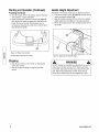 8
8
-
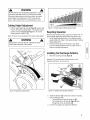 9
9
-
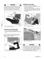 10
10
-
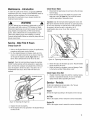 11
11
-
 12
12
-
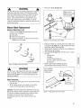 13
13
-
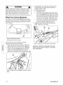 14
14
-
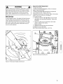 15
15
-
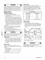 16
16
-
 17
17
-
 18
18
-
 19
19
-
 20
20
-
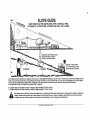 21
21
-
 22
22
-
 23
23
-
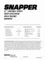 24
24
-
 25
25
-
 26
26
-
 27
27
-
 28
28
-
 29
29
-
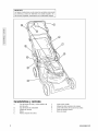 30
30
-
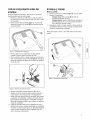 31
31
-
 32
32
-
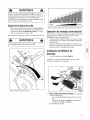 33
33
-
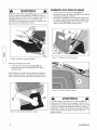 34
34
-
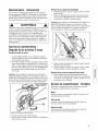 35
35
-
 36
36
-
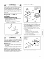 37
37
-
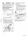 38
38
-
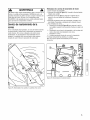 39
39
-
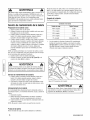 40
40
-
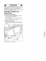 41
41
-
 42
42
-
 43
43
-
 44
44
-
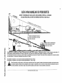 45
45
-
 46
46
-
 47
47
-
 48
48


Snapper 7800179 El manual del propietario
- Categoría
- Cortadoras de césped
- Tipo
- El manual del propietario
- Este manual también es adecuado para
En otros idiomas
- English: Snapper 7800179 Owner's manual
Documentos relacionados
-
Snapper 7800232 Manual de usuario
-
Simplicity OPERATOR'S MANUAL FOR 21-INCH SNAPPER REAR DISCHARGE WALK MOWERS Manual de usuario
-
-
-
-
-
-
Otros documentos
-
-
-
-
-
-
-