Kenmore Elite 79048902000 Guía de instalación
- Categoría
- Hornos
- Tipo
- Guía de instalación
Este manual también es adecuado para

UnitedStates INSTALLATIONAND SERVICEMUST BEPERFORMEDBYA QUALIFIED INSTALLER. ¢onodo
IMPORTANT: SAVE FOR LOCAL ELECTRICAL INSPECTOR'S USE.
READ AND SAVE THESE INSTRUCTIONS FOR FUTURE REFERENCE.
FOR YOUR SAFETY: Do not stere or use gasoline or other
flammable vapors and liquids in the vicinity of this or any other appliance.
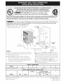
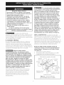
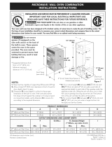
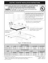
Your new wall oven has been designed |o fit a limited variety of cutout sizes to make the job of ins|alllng easier. The
first step of your installation should be to measure your current cutout dimensions and compare them to the cutout
dimensions chart below for your model. You may find little or no cabinet work being necessary.
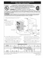
De net remove spacers (if equipped) on the side walls and/or on the back of the built-ln oven.
These spacers center the oven in the space provided. The oven must be centered to prevent excess heat
buildup that may result in heat damage or fire.
* Suggested distance from floor is 111/d' (29.2 cm).
Minimum required distance is 4 1/d' (11.4cm).
1½" (3.8cm)
Min.
44 1/8"
(112.1cm)
DoorOpen
(seenote 2) ..
11½"
(29.2 €
Spacer
2" (5 cm) Wide Wood Spacer if
Needed (seenote 4)
NOTES:
1. Base must be capab{e of supporting 350 pounds (159 kg).
2. Allow at least 21" (53.3 cm) clearance in front of oven for
door depth when it is open.
3. Dimension G (cutout depth) is critical to the proper
installation of the built-in oven. If the oven decorative
trim does not butt against the cabinet, or if noise is heard
on convection models, verify dimension G to assure it is
according to the required dimension.
Electrical
Junction Box
Figure 1
**4. For a cutout height (H) between 441/2" (113cm) and
451/8" (114.6cm) add a 2" (5 cm) ,,vide wood shim of
appropriate height to each side of the opening under the
appliance side rails. Lifting the unit wilt ailow you to hide
the cutout openings showing above the unit The bottom
trim of the unit wilt hide the shims at the bottom.
**5. For a cutout height (H) between 451/8" (114.6cm) and
467/8" (119.1cm) you can order a larger bottom trim
through your Service Center.
PRODUCT DIMENSIONS
MODEL I A J B I c I
30" (76.2 cm) Watl Oven 30 (76.2) 447/8 (114) 281/4 (71.8) 24Vt (62.2)
CUTOUT
30" (76.2 cm) Wait Oven 281/2 (72.4)
All dimensions are in inches (cm).
Printed in United States
29 (73.7) 23Vt (59.7) 44V4 (112.4) 44V2 (113) 30_/8 (76.5)Min
P/N 318201540 (1005) Rev.A
English - pages 1-6
Espa_ol -paginas 6-12

Important Notes to the Installer
1. Read aii instructions contained in these installation
instructions before installing the combination oven.
2. Remove all packing material from the oven compartments
before connecting the electrical supply to the wail oven.
3. Observe all governing codes and ordinances.
4. Be sure to leave these instructions with the consumer.
5. Oven door may be removed to facilitate installation.
6. THIS COMBINATION OVEN IS NOT APPROVED
FOR STACKABLE OR SIDE=BY=SIDE INSTALLATION.
Important Note to the Consumer
Keep these instructions with your Owner's Guide for future
reference. Do not discard oven removal tools found in the
literature bag.
IMPORTANT SAFETY
INSTRUCTIONS
* Be sure your combination oven is installed and
grounded properly by a quallfied installer or service
technician.
* This wall oven must be elecfrlcaily grounded in
accordance wlfh local codes or, in their absence,
wlfh the Natlonal Elecfrlcal Code ANSJ/NFPA No.70=
latest edition in United Sates, or wlth CSA Standard
C22.1, Canadian Elecfrlcal Code, Part 1, in Canada.
Stepping, leaning or sitting on the door
of thls wall oven can result in serious injuries and can
also cause damage to the wall oven.
* Never use your wall oven for warming or heating
the room. Prolonged use of the wail oven without
adequate ventilation can be dangerous.
The elecfrlcal power to the oven must be
shut off while llne connections are being made. Failure
to do so could result in serious injury or death.
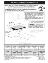
1. Carpentry
Refer to figure 1for the dimensions applicable to your
appliance, and the space necessary to receive the
combination oven. The oven support surface may be solid
plywood or similar material, however the surface must be
leveled from side to side and from front to rear.
2. Electrical Requirements
This appliance must be supplied with the proper voltage and
frequency, and connected to an individual, properly grounded
branch circuit, protected by a circuit breaker or fuse. To
know the circuit breaker or fuse required by your model, see
the serial plate to find the wattage consumption and refer to
table A to get the circuit breaker or fuse amperage.
Appliance Protection Appliance , Protection
Rating Watts Circuit RatingWatts Circuit
240V Recommended 208V Recommended
Lessthan4800W 20A Lessthan4100W 20A
4800W- 7200W 30A 4100W- 6200W 30A
7200W- 9600W 40A 6200W- 8300W 40A
9600Wand+ 50A 8300Wand+ 50A
Table A
Observe all governing codes and local ordinances
1. A 3-wire or 4-wire single phase 120/240 or 120/208 Volt,
60 Hz AC oniy electrical supply is required on a separate
circuit fused on both sides of the line (red and black wires).
A time-delay fuse or circuit breaker is recommended. DO
NOT fuse neutral (white wire).
NOTE: Wire sizes and connections must conform with the
fuse size and rating of the appliance in accordance with the
American National Electrical Code ANSI/NFPA No. 70-latest
edition, or with Canadian CSA Standard C22.1, Canadian
Electrical Code, Part 1,and local codes and ordinances.
An extension cord should not be used
wlfh fhls appliance. Such use may result in a fire,
elecfrlcal shock, or other personal injury. If you need a
longer power cord you can purchase a 10' (3 m) power cord
kit by calling the Service Center.
.
These appliances should be connected to the fused
disconnect (or circuit breaker) box through flexible
armored or nonmetallic sheathed cable. The flexible
armored cable extending from the appliance should be
connected directly to the junction box. The junction box
should be located as shown in Figure 1and with as much
slack as possible remaining in the cable between the box
and the appliance, so it can be moved if servicing is ever
necessary.
3. A suitable strain relief must be provided to attach the
flexible armored cable to the junction box.
In cotd weather shipping and storage
conditions, make sure that oven is in final location at least
three (3) hours before switching on power. Switching on
power while oven is still cotd may damage the oven controls.

Electrical Shock Hazard
* Electrical ground is required on this appliance.
* Do not connect to the electrical supply until
appliance is permanently grounded.
* Disconnect power to the junction box before making
the electrical connection.
* This appliance must be connected to a grounded,
metallic, permanent wiring system, or a grounding
connector should be connected to the grounding
terminal or wire lead on the appliance.
* Do not use a gas supply line for grounding the
appliance.
Failure to do any of the above could result in a fire,
personal injury or electrical shock.
3. Electrical connection
If is the responsibility and obligation of the consumer to
contact a qualified installer to assure that the electrical
installation is adequate and is in conformance with the
National Electrical Code ANSI/NFPA No. 70-latest edition,
or with CSA Standard C22.1, Canadian Electrical Code, Part 1,
and local codes and ordinances.
Risk of electrical shock (Failure to
heed this warning may result in electrocution or
other serious injury.) This appliance is equipped with
copper lead wire. If connection is made to aluminum
house wiring, use only connectors that are approved
for joining copper and aluminum wire in accordance
with the National Electrical Code and local code and
ordinances. When instafflng connectors having screws
which bear directly on the steel and/or aluminum
flexible conduit, do no tighten screws sufflclently to
damage the flexible conduit. Do not over bend or
excessively distort flexible conduit to avoid separation
of convolutions en exposure of internal wires.
DO NOT ground to a gas supply pipe. DO NOT connect
to electrical power supply until appliance is permanently
grounded. Connect the ground wire before turning on the
power.
(if your appliance is equipped with a
white neutral conductor.)
This appffance is manufactured with a white neutral
power supply and a frame connected copper wire.
The frame is grounded by connection of grounding
lead to neutral lead at the termination of the conduit,
if used in USA, in a new branch circuit installation
(1996 NEC), mobile home, recreational vehicles, where
local code do not permit grounding trough the neutral
(white) wire or in Canada, disconnect the white and
green lead from each other and use ground lead to
ground unit in accordance with local codes, connect
neutral lead to branch clrcult-neutral conductor in
usual manner see Figure 3. If your appliance is to
be connected to a 3 wire grounded junction box
(US only), where local code permit connecting the
appllance-groundlng conductor to the neutral (white)
see Figure 2.
NOTE TO ELI:CTRICJAN: The armored cable leads
supplied with the appliance are UL-recognized for connection
to larger gauge household wiring. The insulation of the leads
is rated at temperatures much higher than temperature
rating of household wiring. The current carrying capacity of
the conductor is governed by the temperature rating of the
insulation around the wire, rather than the wire gauge alone.
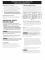
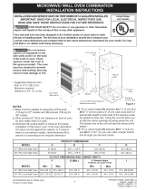
Where local codes permit connecting the appffance-
grounding conductor to the neutral (whffe) wire (US
Only) (see figure 2):
1. Disconnect the power supply.
2. In the junction box:
Connect appliance and power supply cable wires as
shown in Figure 2.
Cable from Power Supply
White Wire
(Neutral) _ :::::;::___
Wires IT Y-J_/\'_
Ground Wire _/ _-_{_
(Bare or Green Wire) _- "
Btack
]
cfion
X
_'i J \White Wire
(Neutral)
U.L-Listed Conduit
Connector (or CSA listed)
Cable from appliance
Figure 2
3-WIRE GROUNDED JUNCTION BOX

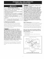
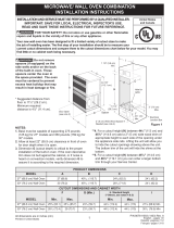
If oven is used in a new branch circuit installation
(1996 NEC), mobile home, recreallonal vehicle, or
where local codes DO NOT permit grounding through
the neutral (white) wire, the appliance frame MUST
NOT be connected to the neutral wire of the 4-wire
electrical system. (see figure 3):
1. Disconnect the power supply.
2. Separate the green (or bare copper) and white appliance
cable wires.
3. In the junction box:
Connect appliance and power supply cable ,,vires as
shown in Figure 3.
Cable from Power Supply
Ground Wie--_ _-_
"X,[_.L_L>.I _ "-'"'"_ ,-White Wire
Red '_cc
Ground Wire ' _/, Wire
(Bare or Oreen---_ _ i_
Wire) _ _ L_:_White Wire
/ L]
Junction Box i _]_,' U"_.L.-ListedConduit
_r4_ Connector (or CSA listed)
Cable from appliance
Figure 3
4-WIRE GROUNDED JUNCTION BOX
Model and Serial Number Location
The serial plate is located along the interior side trim of the
oven and visible when the door is opened.
When ordering parts for or making inquires about your oven,
always be sure to include the model and serial numbers and a
lot number or letter from the serial plate on your oven.
4. Cabinet Installation
Do not llft the oven by the door handle.
Heavy Weight Hazard
* Use 2 or more people to move and install wall oven.
* Failure to follow this instructlon can resuff in injury or
damage to the unff.
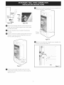
Unpack the wall Remove the bottom trim and the
oven.
center trim taped on the oven side panel.
O Remove the lower oven door to reduce the weight the
of
appliance and to facilitate its handling and its installation.
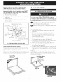
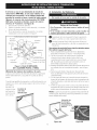
To Remove Oven Door.
1. Open oven door completely (horizontal with floor- See
Figure 4A).
2. Pull the door hinge locks on both left and right door hinges
down from the oven frame completely towards the oven
door (See Figure 4B). A tool such as a small fiat-blade
screwdriver may be required.
3. Firmly grasp both sides of oven door along the door sides
(Do not use the oven door handle- See Figure 4C).
4. Close the door to the broil stop position (the oven door ,,viii
stop into this position iust before fully closing).
5. With the oven door in the broil stop position, lift the oven
door hinge arms over the roller pins located on each side of
the oven frame (See Figure 4D).
6. Proceed in reverse to replace the oven door. Make sure the
hinge supports are fully engaged before unlocking the hinge
levers.
NOTE: The oven door is very heavy. Be sure to have a firm grip
before lifting the oven door off the hinges. Use caution once
the door is removed. Do not lay door on its handle. This could
cause dents or scratches.
Door Hinge
locations
wffh oven
door fully
Figure 4B
4

Oven
door
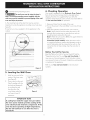
Remove all packaging inside the ovens and remove the
lower oven racks and their supports (see owner's guide
for further instructions).
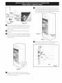
O ind the 2 mounting screws included in the literature
package.
Insert the unit into the cabinet opening. Slide unit inward
leaving 11/t'' (3.8 cm) clearance between the unit and
front of cabinet (see Figure 5).
Install the bottom trim the with
now using suppliedscrews
the unit (Figure 6).
Screws
supplied
Figure 6
Install now the center trim using the screws supplied with
the unit, on both sides (Figure 7).
Figure 5
I
0
Figure 7
O Pull the armored cable the hole for it in the
through
cabinet and toward the junction box while moving the
appliance inward.
5

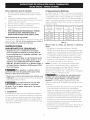
Install the Anti-tip Mounting Screws
The waJJ oven can tlp when the door is
open. The antl-tip mounting screws supplied with the
wall oven must be installed to prevent tipping of the wall
oven and injury to persons.
A. The mounting holes in the side trims may be used as a
template to locate the appliance mounting screw holes (see
Ngure 8).
B. Use the two screws supplied to Nx the appliance to the
cabinet.
Figure 8
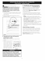
6. Checking Operation
Your model is equipped with an Electronic Oven Control
Each of the functions has been factory checked before
shipping. However, it is suggested that you verify the
operation of the electronic oven controls once more. Refer to
the Use and Care Guide for operation.
,
2.
3_
Remove all items from the inside of the oven.
Turn on the power to the oven (Refer to your Use & Care
Guide.)
Verify the operation of the electronic oven controls:
Bake- Verify that this function makes the oven hot. 20
seconds after turning oven on, open the door and you
should feel heat coming from the oven.
Broil- When the oven is set to BROIL, the upper element in
the oven should become red.
Convection (some models)-When the oven is set for
a convection baking or roasting, both elements cycle on
and oF alternately and the convection fan will run. The
convection fan wilt stop running when the oven door is
opened.
Before You Call for Service
Read the "Before You Calt for Service Checklist" and the
"Operating Instructions" in your Use and Care Guide. It
may save you time and expense. The list includes common
occurrences that are not the result of defective workmanship
or materials in this appliance.
Refer to your Use and Care Guide for service phone
numbers.
5. Leveling the Wall Oven
1. Install an oven rack in the
center of the lower oven
(see Figure 9).
9. Place a level on the rack.
Take 2 readings with the
level placed diagonally
in one direction and
then the other. Use
wood shims under the
,,vail oven to level if
necessary.
Figure 9
iMPORTANT NOTE
A coollng fan inside the upper rear part above
the oven (some models) provides cooling of the
oven electrical and eJectronlc components. If the
oven has been operating at high temperatures,
the fan will continue to run after the oven is
turned off.

EstadosUnidos LA INSTALAClON Y EL SERVIClO DEBEN SER EFECTUADOS POR UN Canada
INSTALADOR CAMFICADO. IMPORTANTE: GUARDE ESTAS INSTRUCCIONES
PARA USO DEL INSPECTOR LOCAL DE ELECTRICIDAD. LEA Y GUARDE ESTAS
INSTRUCCIONES PARA REFERENCIA FUTURA.
I_ PARA SU SEGURIDAD: No alrnacen_ ni utilice gasollna u otros
vapores y licluldos inflarnables en la pro×imldad de este o de cualquler otro artefacto.
El primer paso para su instalaci6n debe de ser el de medlr las dlmenslones de la apertura y compararlas con las
clue se indlcan en el cuadro de dlmenslones del hueco de la figura 1. PoslbJemente encontrarc_ clue alg_n trabajo
de carplnter_a serc_necesarlo.
F_ No quite los separadores de los muros lateraJes o/y de la parte posterior deJ homo empotrado.
Estos espacladores cenfran el homo en el espaclo provlsto. Ei horno debe estar cenfrado para prevenlr una
concenfraci6n e×ceslva de calor clue podria resultar en da_os por el calor o un incendlo.
Distancia sugerida desde el sueto es 111/2'' (2?.2 cm).
La distancia minima requerida es 41/t '' (11.4cm).
NOTAS:
1. La base debe poder sosfener
300 libras (136kg),
2. Deje por Io menos 21" (53,3
cm) de espacio libre para
la profundidad de la puerta
cuando esta abierta.
B Orificio para el
Cable (izquierda,
seg6n el modelo)
Puerfa Abierfa ............
(vea la nora 2) 11½" 3" (7.6 cm)
":..... (29._ € Max.
........ Espaciador Caja
3. La dimensi6n G (profundidad dei corte) est6 primordial
para insfatar correcfamente el homo de pared, Si
et adorno det armaz6n del homo no topa contra el
armario verifique si la dimensi6n G est6 en conformidad
con la dimensi6n requerida,
*'4. Para una attura de cavidad (H) entre 441/2" (113cm)
y 451/8" (114,6cm), coloque cutlas de madera de 2"
(Scm) de ancho con la altura adecuada en cada
Espaciador de Madera de 2" (5cm)- de empatme
(izquierda)
de ancho, sies necesario (vea nora 4)
Figura 1
lado de la abertura debajo de los deles laterales del
electrodom_stico, AI levantar Jaunidad podr6 ocultar las
aberturas de la cavidad visibtes en la parte superior de
la unidad, La motdura inferior de la unidad ocultarc_ las
cutlas de la parte inferion
*'5. Para una altura de cavidad (H) entre 451/8 '' (114,6cm)
y 467/8 '' (119,1cm) puede soticitar una moldura inferior
m6s grande a trav&s de su Centro de Servicio,
DIMENSIONES DEL APARATO
MODELO' A' B I c I D
30" (76.2 cm) 30 (76.2) 447/8 (114) 28_/4 (71.8) 24_/2 (62.2)
DIMENSIONES DEL HUECO Y ANCHURA DEL ARMARIO
30" (76.2 cm) 28V2 (72.4) 29 (73.7)
Todas las dimensiones se dan en puigadas (cm).
lmpreso en losEstadosUnidos
23Vt (59.7) 44V4 (112.4) 44V2 (113) 30_/8 (76.5)Min
P/N 318201540 (1007)Rev.A
English- pages 1-6
Espa_ol -paginas 6-12

Notasimportantes para el instalador
1. Lea todas ias instrucciones contenidas en este manual
antes de instalar el combinaci6n microondas ,/horno de
pared.
2. Saque todo el material usado en el embalaje del
compartimiento dei horno antes de conectar ei suministro
el&ctrico o de gas a la estufa.
3. Observe todos los c6digos y regiamentos pertinentes.
4. Deje estas instrucciones con el consumidor.
5. La puerta del horno se puede retirar para facititar la
instaiaci6n.
6. ESTE COMBINACION MICROONDAS / HORNO
DE PARED NO ESTA APROBADO PARA LA
INSTALACION APILABLE O DE LADO A LADO.
Nora importante al consumldor
Conserve estas instrucciones y ei manual del usuario para
referencia futura. No tirar los herramientas para retirar el
horno incluidas en Ja bolsa de Ja Jiteratura,
INSTRUCCIONES
IMPORTANTES DE SEGURIDAD
* Aseg_rese de que su combinacJ6n microondas /
homo de pared sea instalado y puesto a fierra de
forma apropiada pot un instalador calificado o pot
un t_cnlco de servlclo.
" Este homo de pared debe set el_ctrlcamente puesto
a tierra de acuerdo con los c6digos locales o, en su
ausencla, con el C6dlgo El_ctrlco Naclonal ANSI/
NFPA No. 70-01fima edlci6n en los Estados Unldos, o
el C6dlgo El_ctrlco Canadlense CSA Standard C22.1,
Part 1, en Canad6.
PJsarr apoyarse, o sentarse sobre Ja
puerto de este homo de pared puede cousar serlas
leslones y dafios al homo de pared.
• Nunca use su horno de pared para calentar una
habifaci6n, El uso prolongado de la estufa sin la ventitaciGn
adecuada puede ser peiigroso.
La corrlente el_ctrlca al homo debe
estar apagoda mlentras se hacen los conexlones
de lineas. Si no se apaga, dodos serlos o la muerte
podrian resultar.
1. Carpinteria
Consulte la Figura 1 para conocer las dimensiones pertinentes
al modeto de su homo y al espacio necesario en el que poner
el homo. Lasuperflcie donde se va a apoyar el homo debe de
ser de madera contrachapada sSlida u otro material similar y,
sobre todo, la superflcie tiene que estar a nivel, de lado a lado,
y de atr6s hacia adelante.
2. Requerimientos El_ctricos
Se debe proveer el vottaie y la frecuencia apropiados a
este electrodom&stico, y conectarse a un circuito individual
correctamente _uesto a tierra, protegido por un interruptor o
un fusible. Para conocer ei interruptor o fusibte que requiere su
modeio, vea la placa serial para encontrar la consumaci6n det
vatiaje y reflerase al flgura 2 para encontrar el amperaje del
interruptor o fusible.
Grados cie Se recomienda Gradoi de Va!!0s se iecgmienda
Vahos deJ una protecc_on del una Pr0tecc 6n
electrodom6stico al Circuito electroclom_stico al circuito
2_OV - 20aV I
Menos de 4800W 20A Menos de 4100W 20A
4800W - 7200W 30A 4100W - 6200W 30A
7200W - R600W 40A 6200W - 8300W 40A
9600W and + 50A 8300W and + 50A
Table A
Observe todos los c6dlgos que goblernan y ordenanzas
locales
I Un cable de 3 o 4 alambres monof6sico 120/240 o
120/208 vottios, 60 hertzios es la _nica fuente et_ctrica que
requiere en un circuito separado en ambos lados de la linea
(alambre negro y alambre rojo) (se recomienda un fusible
o un interruptor de retraso de tiempo). No funda a cable
neutro (alambre btanco). Se debe de tener precauci6n al
combinar un horno de pared y una cubierta, refl_rase a la
placa de seria de cada uno de los aparatos.
NOTA: LostamaSos y las conexiones del alambre deben
conformarse con et tamaSo del fusible y el grado de la
aplicaci6n de acuerdo con el c6digo El_ctrico Nacional
Americano ANSI/NFPA No. 70- ultima edici6n, o con et
est6ndar CSA canadiense C22.1, c6digo el_ctrico canadiense,
parte 1,y c6digos y ordenanzas locales.
No se debera usar extensiones para
enchufar este elec|rodom_stlco. Esto podria causar
un incendlo, choque el_ctrlco u otro ffpo de da_o
personal, Si usted necesita un cable mas largo, puede
ordernar un cable de 10" kit 903056-9010 Ilamando al centro
de Servicio.
2. Este dectrodom_stico debe conectarse a Ja caja de fusibles
(o de cortocircuito), por medio de un cable bHndado
flexible o un cable con forro no met6Jico. EJcable bJindado
flexible que va desde el electrodom_stico debe de estar
conectado directamente a Jacaja de empaJme. La caja de
empalme debe de estar Iocalizada en el lugar que se indica
en Ja Figura 1o 2, dejando tanto exceso de cable como sea
posible entre la caja y el electrodom_stico, de forma que
asi eJ dectrodom_stico se pueda mover f6cilmente, sifuera
necesario para hacer una reparaci6n.
3. Se debe de usar un conector que reduzca la tirantez de una
forma adecuada para unir el cable btindado flexible a la
caja de empalme.

Riesgode choque eJ_ctrlco
* Una puesta a tlerra se reclulere en es|e apara|o.
* No Io conecte a Ja corrlente el_ctrlca basra que el
aparato hava sldo puesto a flerra.
* Desconecte la corrlente el_ctrlca a la caja de
empalmes antes de hacer la conexi6n el_ctrlca.
* Este aparato debe estar conectado con un
slstema de aJambres puesto en tlerra, metc'lJlco
y permanente o un conector de puesta a tlerra
debe conectarse al terminal de puesta a tlerra o el
aJambre conductor en al aparato.
* No utillce el surnlnlstro de gas para hacer la
puesta a tlerra.
La falta de cualqulera de las instrucclones
menclonadas podria resultar en un incendlo, choque
el_ctrlco o leslones personales.
En cuanto a las condiciones de
despacho y atmacenamiento en ei invierno, aseg0rese de que
et horno Itegue a su destino final como minimo tres (3) horas
antes de encenderto. Si se enciende et horno cuando a0n estc_
frYo,se pueden da_ar los controles.
3. Conexi6n el_ctrica
El usuario tiene la responsabilidad personal y obtigaci6n
de utilizar un instatador catificado, para asegurar que la
instalaci6n et_ctrica est_ hacha de forma adecuada y est_
conforme con el C6digo El_ctrico Nacional ANSI/NFPA No.
70-01tima edici6n en los Estados Unidos, o et C6digo El_ctrico
Canadiense CSA Standard C22_1,Part 1,en Canad&
Riesgo de choque el_cfrlco
(El no presfar afend6n a esfa adverfencla puede
resuffar en eJecfrocuci6n u ofras leslones graves.)Esfe
elecfrodom_sffco esfc_equlpado con aJambre de cobre.
Si se va a conecfar con cableado de alumlnlo del hogar,
ufffizar _nlcamenfe conecfores clue esfcin aprobados
para unlr cobre y alumlnlo de acuerdo al C6dlgo
Naclonal El_cfrlco (NEC pot sus slglas en ingles) y leyes
y c6dlgos locales, AI insfalar conecfores con fornlJJos clue
empujen dlrecfamenfe confra el acero y/o aJumlnlo deJ
conducfo flexible, no aprefar los fornillos suflclenfemenfe
que darien el conducfo flexible. No doblar de mc_so
deformar el conducfo flexible para evlfar separar el
esplral y descubrlr los alambres infernos.
NO conecte el alambre puesto a tierra a una tuberia de
suministro de gas. NO conecte el suministro de energia
et_ctrica hasta que el electrodom_Zstico haya sido
permanentemente puesto a tierra. Conecte et alambre
de puesto a tierra antes de enchufar por primera vez el
etectrodom_Zstico_
(Si su elecfrodom_sffco esf6 equlpado
con un conducfor neufro bJanco.) Esfe elecfrodom_sffco
esf6 fabrlcado con un sumlnlsfro el_cfrlco neufro
bJanco V un aJambre de cobre conecfado aJ armaz6n.
El arrnaz6n esfa puesfo a fferra pot un enJace de Ja
conexi6n a fferra con Ja conexi6n deJ neufro aJ final
de Ja Jinea eJ_cfrlca, sl es usado en los esfados unldos
una nueva insfalaci6n de clrculfo de blfurcaci6n
(1996 NEC), casa rodanfe, vehiculos recreaclonales, o
donde los c6dlgos locales no permlfan poner a flerra
medlanfe el neufro (bJanco) o en Canad6, desconecfar
la conexi6n blanca de la verde y uffllzar la conexi6n
a flerra para poner a flerra Ja unldad de acuerdo a
los c6dlgos locales, conecfar el neufro al clrculfo de
blfurcaci6n= conducfor neufro de rnanera usual. Vet
Figura 3. Si su eJecfrodom_sffco va a set conecfado a
una caja de conexi6n puesfa a flerra de 3 cables (en los
esfados unldos soJamenfe), donde los c6dlgos locales
perrnlfan conecfar el conducfor de poner a fferra=
eiecfrodom_sffco con el neufro (bJanco) vet Figura 2.
NOTA AL ELECTRICISTA: Los conductores de cable
btindados provistos con este artefacto son aprobados por UL
para la conexi6n at alambrado de casa de un calibre mayor.
El aistamiento de los conductores estc_calificado para
temperaturas m_s altas que las del alambrado de la casa. La
capacidad de corriente del conductor estc_gobernada por la
calificaci6n de la temperatura del aislamiento alrededor del
alambre en vez de solamente el calibre det alambre_
Donde los c6dlgos locales permlfan conecfar el
conducfor de puesfa a flerra del eiecfrodom_sflco al
neufral (blanco) (Solamenfe en los Esfados Unldos)
(yea flgura 2):
1. Desconecte el suministro et_ctrico.
9. En el caia de iuntas: conectar el aparato y los cables
residenciales como se muestra en la figura 3_
Cable desde el suministro de energia
Alambre
desnudo
negros
Alambre
rojos
Alambre verde
o desnudo
de
empalmes
Alambre
desnudo
Conductor de uni6n
listado-UL (o CSA)
Cable de la estufa
Figura 2 - CAJA DE EMPALMES
DE 3 ALAMBRES PUESTAA TIERRA

Si el horno se usa en una instalaci6n de circuito de
ramal nuevo (1996 NEC), en una casa rodante, en un
vehiculo para recreaci6n o sl los c6digos locales NO
permiten la conexi6n a tierra a tray, s del cable neutral
(blanco), el armaz6n del electrodom_stlco NO TIEBIE
QUE estar conectado aJ aJambre neutro deJ slsterna
el_ctrlco de 4 alambres (ver figura 3):
1. Desconecfe el suminisfro el_cfrico
2. Separe el alambre verde (o cobre desnudo) y el alambre
btanco del elecfrodom&sfico.
3. En el caja de junfas: conecfar el aparafo y los cables
residenciaies como se muesfra en ia figura 3.
Cable desde el suministro de energia
Alambre /-_--_ /
desnudo Alambre
Aiambre _ blanco
Aiambre
Aiam negros
verde
desnudo __-_" \_.J "
/ __ Atambre blanco
Ca'jade _-_ "_Conductor de uni6n
__ --listado-UL (o CSA)
Cable de ia esfufa
Figura 3- CAJA DE EMPALMES
DE 4 ALAMBRES PUESTA A TIERRA
Ubicaci6n del n0mero de modelo y de serle
La pIaca con ei nOmero de serie est8 ubicada en ta guarnici6n
interior Iaferai det horno y se puede ver cuando seabre ta
puerta.
Cuando haga pedidos de repuestos o soticite informaci6n con
respecto a su horno, est& siempre seguro de incluir et n0mero
de modeto y
de serie y el
n0mero o letra La plata de
dei lore de la serie estc_
placa de serie ubJcada aqui.
de su homo.
4. Instalaci6n del Gabinete
No levante el homo pot la manija de la puerta.
Peligro de Peso Pesado
• Use 2 personas o m6s para mover e instalar el homo
de pared.
• Si no cumple con esta instrucci6n, puede resuJtar en
Jesiones personales o daBos al homo de pared
Desembalar el horno de Extraer la
pared. guarnici6n
inferior y central con cinta at panel lateral det homo.
O Extraiga la puerta inferior deJ horno para alivianar el
peso del eiectrodom&stico y facititar su manipulaci6n e
instalaci6n.
Para extraer ia puerta deJ horno, sisigalos siguientes pasos:
Para retirar la puerta del horno:
1. Abra comptetamente ta puerta det homo (dejandola
horizontal en relaciSn con el piso -vea Ia Figura 4A).
2. Tire de los bloqueos de ambas bisagras (izquierda
y derecha) hacia abajo desde el marco del homo
completamente hacia la puerta det horno (vea la Figura
4B). Es posibte que necesite una herramienta como un
destorniiiador peque_o de cabeza piana.
3. Sostenga firmemente ambos iados de ia puerfa dei horno en
suscostados (no use ta manila de ta puerta -vea ta Figura
4C).
4. Cierre ta puerfa basra et tope de asar (ia puerfa det
horno se detendr6 en esta posici6n justo antes de cerrarse
completamente).
5. Con Ia puerta deI horno en ta posici6n de asar, Ievante los
brazos de Ias bisagras de ia puerta sobre los pasadores de
rotaci6n ubicados a cada tado det marco det homo (vea ta
Figura 4D).
B. Invierta los pasos para votver a coiocar la puerta det horno.
Aseg0rese de que los soportes para bisagra est&n bien aco-
plados antes de desbioquear las paiancas para bisagras.
BIOTA: Lapuerta es pesada. Para guardaria temporaimente de
manera segura, deposite la puerta horizontalmente con el lado
interior dirigido hacia abajo.
Ubicaci6n de
Jas bisagras
con Ja puerta
completamente
abierta
Bloquf
Figura 4A
10
Figura 4B

O ©uite todo ei material de empaque dei interior de los
hornos y extraiga las parriiias inferiores y sus soportes
(consuite la guYadel propietario para obtener mSs
instrucciones).
O Buscar los tornittos que se incluyen en el paquete de
iiteratura.
O nsertar et homo en la abertura det gabinete. Destizar
et homo hacia dentro dejando 11/2'' (3,8 cm) de espacio
iibre entre ei homo y ia parte deiantera dei gabinete
(ver la Figura 5).
Colocar la parte superior de la guarnici6n sobre
inferior
las lengi;etas laterales det homo, debajo de la puerta det
homo, y fijartas usando los 2 tornillos provistos con los
orificios de montaje ubicados a cada lado del marco del
homo (ver la Figura 6).
Ternilles
O hora instate la motdura centrat en ambos lados con los
tornittos proporcionados con la unidad (figura 7).
_,._-'""1"]/2" (3]8 cm)
entre
la unidad y et
gabinete
E_
@
Figure 7
Figura 5
O Empujar et cable blindado a trav&s det orificio del
gabinete y hacia la caja de paso mientras se destiza et
accesorio hacia adentro.
11

Instalaci6n de los tornillos de montado
El homo de pored puede incllnorse
cuando Jo puerto esto obJerta. Los soportes de
montoje clue vlenen con el homo de pored deben
de ester ojustodos ol ormorlo ¥ oJ operate pore
evltor que el homo de pored se incline y ocoslone
quemoduros groves.
A. Losbarrenos en las molduras laterates pueden ser usadas
coma guYapara Iocalizar los tornitlos de montado de la
unidad (figura 8).
B. Use los dos torniltos proporcionados para colocar la
unidad en la cabina.
Figura 8
6. VeriNcaci6n del funcionamiento
Su modeIo estd_equipado con un Control Electr6nico de
Horno. Cada una de tas funciones ha side controIada en
fc_brica antes deI despacho. Sinembargo, te sugerimos
verificar el funcionamiento de los controtes eIectr6nicos una
vez mc_s.Consulte Ia Guio de Usa y Cuidado para ver et
funcionamiento det borne.
1.Extraer redes los elementos de Ia parte interior deI borne.
2. Encender el borne (Consular Ia Guia de Usa y Cuidado.)
3. Verificar et funcionamiento de los controtes etectr6nicos det
borne:
Hornear - Verificar que esta funci6n catiente el borne.
Veinte minutes despu&s de encender el borne, abrir ia puerta
y versi se siente que el cater emana desde su interior.
Asor- Cuonda se pone el horno para asar, el elemento
de arriba del borne debe de ponerse role.
Cenvecci6n (olgunas rnodelos)-Cuando se configura el
borne en la funci6n de horneado o asado par convecci6n,
ambos elementos se encienden ciclicamente, y el
ventilador de convecci6n comienza a funcionar. Cuando se
abre la puerta del borne, et ventitador de convecci6n deja
de funcionar.
Antes de llarnar al servicio
Lea la secci6n Lista de Antes de Ilamar en su Manual dei
Usuario. Esto le podrc_ ahorrar tiempo y gastos. Esta lista
incluye ocurrencias comunes que no son et resultado de
defectos de materiales o fabricaci6n de este artefacto.
Lea la garantYa y la informaci6n sabre el servicio en su
Manual del Usuorio para obtener et n0mero de tet_fono
gratuito y la direcci6n det servicio.
5. Aseg rese de que el Borne de
pared est6 a nivel
1. Instale una rejitta al centre det borne superior (vea la
Figura 9).
2. Ponga un nivei par encima de ......
la rejilla. Lea 2 veces, una
vez con ei nivet a la posici6n
de lade a lade, y otra vez de
atrc'_shacia adeiante. Utitice
trozo de madera o cu_as par
debajo det borne de pared
para niveiar, si sea necesario.
Figura 9
Un ventlJodor ublcodo dentro de Jo parle trosero
superior orrlbo del homo (en olgunos modelos)
permlte Jo refrlgeroci6n de los componentes el_ctrlcos
y electr6nlcas de enfrlomlen|a. Si el homo ha estodo
funclonondo o olios temperatures, el ventilodor
segulrci funclonondo despu&s de opogor el homo.
12
-
 1
1
-
 2
2
-
 3
3
-
 4
4
-
 5
5
-
 6
6
-
 7
7
-
 8
8
-
 9
9
-
 10
10
-
 11
11
-
 12
12


Kenmore Elite 79048902000 Guía de instalación
- Categoría
- Hornos
- Tipo
- Guía de instalación
- Este manual también es adecuado para
En otros idiomas
Documentos relacionados
-
 Kenmore Elite 79048802100 Guía de instalación
-
 Kenmore Elite 79048913411 Guía de instalación
-
 Kenmore Elite 49113 Guía de instalación
-
Kenmore 79048083000 Guía de instalación
-
Kenmore 79048173002 Guía de instalación
-
Kenmore 79043920001 Guía de instalación
-
 Kenmore Elite 79045313410 Guía de instalación
-
Kenmore 79041279000 Guía de instalación
-
 Kenmore Elite 79041279000 Guía de instalación
-
Kenmore Elite 79041093100 Guía de instalación


