
600 South Rockford Drive • Tempe, Arizona 85281 United States
Direct: (480) 967-3565 • Toll Free: (800) 669-9899
rockfordfosgate.com
013020 1230-73054-01-D Printed In China
M2D4-10I
M2D4-10IB
M2D2-10I
M2D2-10IB
Installation assistance available at:
ELEMENT READY™ SUBWOOFERS
Installation & Operation

2
Dear Customer,
Congratulations on your purchase of the world’s finest brand of audio
products. At Rockford Fosgate we are fanatics about musical reproduc-
tion at its best, and we are pleased you chose our product. Through
years of engineering expertise, hand crasmanship and critical testing
procedures, we have created a wide range of products that reproduce
music with all the clarity and richness you deserve.
For maximum performance we recommend you have your new Rock-
ford Fosgate product installed by an Authorized Rockford Fosgate
Dealer. Please read your warranty and retain your receipt and original
carton for possible future use.
Great product and competent installations are only a piece of the
puzzle when it comes to your system. Make sure that your installer is
using 100% authentic installation accessories from Rockford Fosgate in
your installation. Rockford Fosgate has everything from RCA cables and
speaker wire to power wire and battery connectors. Insist on it! Aer
all, your new system deserves nothing but the best.
To add the finishing touch to your new Rockford Fosgate image, order
your Rockford accessories, which include everything from T-shirts to
hats.
Visit our web site for the latest information on all Rockford products;
www.rockfordfosgate.com
or, in the U.S. call 1-800-669-9899 or FAX 1-800-398-3985. For all
other countries, call +001-480-967-3565 or FAX +001-480-966-
3983.
Table of Content
If, aer reading your manual, you still have questions regarding
this product, we recommend that you see your Rockford Fosgate
dealer. If you need further assistance, you can call us direct at
1-800-669-9899. Be sure to have your serial number, model num-
ber and date of purchase available when you call.
Safety
This symbol with “WARNING” is intend-
ed to alert the user to the presence of
important instructions. Failure to heed
the instructions could result in severe
injury or death.
This symbol with “CAUTION” is intend-
ed to alert the user to the presence of
important instructions. Failure to heed
the instructions could result in injury
or unit damage.
• To prevent injury and damage to the unit, please read and
follow the instructions in this manual.
• If you feel unsure about installing this system yourself, have
it installed by a qualified Rockford Fosgate technician.
• Before installation, disconnect the battery negative (-)
terminal to prevent damage to the unit, fire and/or possible
injury.
Introduction
©2019 RockfordCorporation. All Rights Reserved. ROCKFORD FOSGATE, PUNCH
®
and associated logos where applicable are registered trademarks of
Rockford Corporation in the United States and/or other countries. All other trademarks are the property of their respective owners. Specifications sub-
ject to change without notice.
2 Introduction
3 Specifications
4-5 Diagrams
6 Installation Considerations
Mounting
7-9 Wiring
10-25 Additional Languages
French
Spanish
German
Italian
28 Limited Warranty Information
PRACTICE SAFE SOUND
Continuous exposure to sound pressure levels over 100dB may
cause permanent hearing loss. High powered auto sound systems
may produce sound pressure levels well over 130dB. Use common
sense and practice safe sound.
PRATIQUEZ UNE ÉCOUTE SANS RISQUES
Une exposition continue à des niveaux de pression acoustique
upérieurs à 100 dB peut causer une perte d’acuité auditive
permanente. Les systèmes audio de forte puissance pour auto
peuvent produire des niveaux de pression acoustique bien au-delà
de 130 dB. Faites preuve de bon sens et pratiquez une écoute sans
risques
PRACTIQUE EL SONIDO SEGURO
El contacto continuo con niveles de presión de sonido superiores
a 100 dB puede causar la pérdida permanente de la audición. Los
sistemas de sonido de alta potencia para automóviles pueden
producir niveles de presión de sonido superiores a los 130 dB. Aplique
el sentido común y practique el sonido seguro.
PRAKTIZIEREN SIE SICHEREN SOUND
Fortgesetzte Geräuschdruckpegel von über 100 dB können beim
Menschen zu permanentem Hörverlust führen. Leistungsstarke
Autosoundsysteme können Geräuschdruckpegel erzeugen, die weit
über 130 dB liegen. Bitte wenden Sie gesunden Menschenverstand an
und praktizieren Sie sicheren Sound.
OSSERVATE LE REGOLE DEL SUONO SENZA PERICOLI
La costante esposizione a livelli di pressione acustica al di sopra dei
100dB possono causare la perdita permanente dell’udito. I sistemi
audio ad alta potenza possono produrre livelli di pressione acustica
ben superiori ai 130dB. Si consiglia il buon senso e l’osservanza delle
regole del suono senza pericoli

3
Specifications
VERIFIED WITH KLIPPEL
To adorn the ‘Verified with Klippel’ mark, the qualifying company’s loudspeaker engineering personnel must be trained
and certified by Klippel prior to using the three separate Klippel systems to design, develop and test. Rockford Fosgate
has made the investment in Klippel to deliver the best possible speakers and subwoofers to their customers.
* All measurements taken with voice coils wired in series
Model
M2D2-10I/IB
M2D4-10I/IB
Nominal Diameter
10”
(254mm)
Description
Subwoofer
Nominal Impedance (Ohms)
2 or 4 Ω DVC
Frequency Response (Hz)
20-750
Voice Coil Diameter - inch (mm)
1.95” (2-Layer)
(49.5mm)
Power Handling - Watts (RMS/Peak)
400/1600
Fs - Free Air Resonance (Hz)
43
Qts
0.74
Vas - cu. . (Liter)
1.56
3
(44.2L
Displacment -cu. fl.
(Liter)
0.1
3
(2.03L)
Sensitivity (2.83V/1M)
90.3dB
Xmax - inch (mm)
0.51”
(13mm)
Grille/Trim Ring
YES
LED Current Draw 0.25 Amps
Recommended Fused Rating For
LED’s (not included)
1 Amp
LED Voltage Range 9-16 Volts

4
Diagrams
Model
M2D2-10I/IB
M2D4-10I/IB
Overall Diameter
(A)
11.5”
(293mm)
Screw Mounting
Diameter (B)
10.16”
(258mm)
Mounting Screw
Angle (C)
6X60°
Overall Height
(D)
6.45”
(163.8mm)
Mounting Depth
(E)
4.46”
(113.3mm)
Cut-out Diameter
(F)
8.9”
(225mm)
Grill Height
(G)
2”
(50.8mm)
A
C
B
F
E
D
G
A
C
B
F
E
D
G
illus.-1.1
illus.-2.1

5
Diagrams
Sport Grill
Stainless Steel Grill

6
• (1)Element Ready™
Subwoofer with Sport/
Stainless Grill
• (6) Socket Head Stainless
Screws
• (1) COLOR OPTIX™ Harness
• (1) 1/8” Drill Bit
• (1) Socket head driver bit • Installation and Operation
Manual
Installation
OPTIMAL ENCLOSURE
Infinite Bale
An Infinite Bale enclosure design represents an application where
the compliance of the air volume within the enclosure is greater than
the compliance on the speaker’s suspension (Vas). An infrasonic filter
is required for reliable performance.
Infinite Bale 10”
F
3
- 3dB Point (Hz) 49.2
Vas - cu. . (Liter) 1.56
(44.2)
Qtc - Enclosure Damping 0.74
IMPORTANT: A subsonic or “infrasonic” filter at or above the
resonant frequency (Fs) of the speaker is required.
NOTE: Infinite bale installations will result in lower speaker
power handling when compared to fully enclosed applications
such as sealed or vented enclosures.
Wiring Configurations
By varying the wiring configuration of your speakers you can create
an impedance load to match your system. Altering the wiring configu-
rations gives a range of options for impedance loads. Series, Parallel,
or Series-Parallel wiring configurations are dierent techniques for
wiring speakers that provide dierent loads. Series configuration is a
string method where speakers are wired end to end. Parallel configu-
ration uses two or more speakers wired across common terminals.
Series-Parallel configuration combines both techniques. Choose the
wiring diagram that corresponds to the number of woofers and the
impedance of your amplifier.
Subwoofer Crossovers
There are two operational types of crossovers, passive and active.
Passive crossovers (coils or inductors) are placed on the speaker
leads between the amplifier and speaker. An active crossover is an
electronic filter that separates the audio signal fed to dierent ampli-
fiers. For optimum subwoofer performance, we recommend using an
active 80-100Hz low-pass crossover at 12dB/octave.
Storage or
Cavity Area
Baffle Board
Subwoofer
OPTIONAL ENCLOSURE
Recommended Sealed Enclosure Volume Range
Sealed Enclosures 10”
V
b
- Volume range cu. . (Liter) 0.75 to 1.25
(21.24 - 35.4)
Vented Enclosures
NOTE: Vb is the internal volume, before any speaker and/or port
displacement is added. All external dimensions were based on
the use of 3/4” (1.90cm) materials.
NOTE: When using enclosures other than recommended, call
Technical Support for correct application.
Optimum Vented (Ported) Enclosure Sizes
Vented Enclosures 10”
Total Internal Volume cu. . (Liter) 1.45
(41.06)
Woofer Displacement cu. . (Liter) 0.1 (2.83)
Port Displacement cu. . (Liter) 0.1 (2.83)
V
b
- Net Internal Volume cu. . (Liter) 1.25 (35.4)
F
B
- Tuning Frequency (Hz) 40
F
3
- 3dB Point (Hz) 39
H - Height - inch (cm) 15.0 (38.1)
W - Width - inch (cm) 15.0 (38.1)
D - Depth - inch (cm) 15.25 (38.74)
P - Port Diameter and Length - inch (cm)
3 x 9.5
(7.62 x 24.13)
NOTE: The port shown can be placed on any face of the enclosure as
long as the port ends are not obstructed.
NOTE: When using vented enclosures, for maximum reliability and
power handling ensure, that a subsonic or “infrasonic” filter is used
so that only usable low frequency signal is sent to the subwoofer.
Contents
3/4" MDF
H
W
D
P

7
Installation Considerations
Before beginning any installation, follow these simple rules:
1. Be sure to carefully read and understand the instructions
before attempting to install these speakers.
2. For easier assembly, we suggest you run all wires prior to
mounting your speakers in place.
3. Use high quality connectors for a reliable installation and
to minimize signal or power loss.
4. Think before you drill! Be careful not to cut or drill into gas
tanks, fuel lines, brake or hydraulic lines, vacuum lines or
electrical wiring when working on any vehicle. If installation
in a boat, take care not to cut or drill through the main hull.
5. Never run wires underneath the vehicle. Running the wires
inside the vehicle or hull area provides the best protection.
6. Avoid running wires over or through sharp edges. Use
rubber or plastic grommets to protect any wires routed
through metal, especially the firewall.
Mounting
1. Determine where the speakers will be mounted. Ensure an
area large enough for the speaker to mount evenly. Be sure
that the mounting location is deep enough for the speaker
to fit; if mounting in a door, operate all functions (windows,
locks, etc.) through their entire operating range to ensure
there is no obstruction.
2. Refer to the specification chart to determine the proper
diameter hole to cut for your speaker model. Cutting and
mounting templates can be found at www.rockfordfosgate.
com.
3. Mark the locations for the mounting screws. Drill the holes
with a 1/8” bit.
4. Feed the speaker wires through the cutout and connect to
the speaker terminals. Be sure to observe proper polarity
when connecting the wires. The speaker’s positive terminal
is indicated with a “+”.
5. Fit the trim ring over the speaker and mount into place
using the four (4) screws that are provided.
6. Tighten the screws until the speaker is snug in place to
prevent rattling. Do not over tighten the screws.
Installation

8
illus.-4.1
SPEAKER TERMINAL SWITCH SPEAKER & COLOR OPTIX™ TERMINALS
Wiring

9
D4 Impedance Options
D2 Impedance Options
Woofer Series Wiring Options
D2 with Switch on 4 Ω
D2 with Switch on 1 Ω
D4 with Switch on 8 Ω
D4 with Switch on 2Ω
Woofer Parallel Wiring Options
2Ω
2Ω
8Ω
8
1Ω
4Ω
4
1
4Ω
4Ω
2Ω
2
2Ω
2Ω
8Ω
8
1Ω
4Ω
4
1
4Ω
4Ω
2Ω
2
Wiring
2Ω
2Ω
8Ω
8
1Ω
4Ω
4
1
4Ω
4Ω
2Ω
2
2Ω
2Ω
8Ω
8
1Ω
4Ω
4
1
4Ω
4Ω
2Ω
2
2Ω
2Ω
8Ω
8
1Ω
4Ω
4
1
4Ω
4Ω
2Ω
2
2Ω
2Ω
8Ω
8
1Ω
4Ω
4
1
4Ω
4Ω
2Ω
2

10
1 - RED (Ground Input)
2 - Yellow (12V + Input)
3 - Blue (Ground Input)
4 - Green (Ground Input)
Included with speakers
Connector is DEUTSCH™/Amphenol style DT06-4S
COLOR OPTIX™ Wiring Precautions
• Do not connect to 24 Volt electrical systems
• We recommend only using the COLOR OPTIX™ wiring chart
or connecting to the PMX-RGB. Connecting any other way
could cause damage to the speakers or the device you have
connected to.
• We recommend installing a fuse (not included) on the
Yellow 12 Volt wire whenever you are NOT using the PMX-
COLOR OPTIX™. See COLOR OPTIX™ wiring chart for wiring
options.
• Rockford recommends a minimum of 20 gauge wire when
hard wiring your COLOR OPTIX™ speakers.
• Never wire the COLOR OPTIX™ lights directly to 12 volts.
Utilize either the PMX-RGB or a toggle switch (not included)
connected to a fused 12 volt power supply. Refer to the
specification to determine the size of fuse (not included)
needed
COLOR OPTIX™ Wiring
If not using the PMX-RGB, follow the diagrams below for proper
pin out and hard wiring instructions.
COLOR OPTIX™ Pin Out (wire side) COLOR OPTIX™ Connector
Speaker Pin Out (wire side)
1 - RED - Positive Speaker Input
2 - BLACK - Negative Speaker Input
NOT included with speakers
Connector is DEUTSCH™/Amphenol style DT06-2S
SPEAKER Wiring
There are (2) dierent options for wiring your speakers.
Use the included spade connectors (included) as seen in illustra-
tion 3.1
You can also utilize the DEUTSCH™/Amphenol style connector
(not included) input next to the COLOR OPTIX™ connector.
COLOR OPTIX™ WIRING OPTIONS
LED OUTPUT COLOR CONNECT THIS COLOR WIRE
TO GROUND
RED RED
GREEN GREEN
BLUE BLUE
YELLOW RED & GREEN
PINK RED & BLUE
AQUA GREEN & BLUE
WHITE RED, GREEN & BLUE
Connect colored wires on right to make output color
on le.
Connect all Yellow wires together to switched 12
Volts. See Wiring Precautions.
illus.-4.2
Included
illus.-4.3
1 2
Wiring
1 2
3 4
illus.-4.1

11
Bale infini
Un design de suspension acoustique représente une application où la confor-
mité du volume d'air dans l'enceinte est supérieure à la conformité sur la
suspension du haut-parleur (Vas). Un filtre infrasonique est requis pour une
performance fiable.
Bale infini 10”
F
3
- 3 dB Point (Hz) 49.2
Vas - pi3 (litre) 1.56
(44.2)
Qtc - Amortissement d'enceinte 0.74
IMPORTANT : Un filtre subsonique ou « infrasonique »
à ou au-dessus de la fréquence de résonance (Fs) du haut-parleur est
requis.
NOTE : Les installations de bales infinis résulteront en tenue en puis-
sance de haut-parleur inférieure quand comparées aux applications
complètement fermées telles que les enceintes scellées ou ventilées.
Configurations de câblage
En variant la configuration de câblage des haut-parleurs, il est possible de
créer une charge d'impédance correspondant à votre système. Altérer les
configurations de câblage ore une gamme d'options pour les charges d'im-
pédance. Les configurations de câblage en série, en parallèle ou en série-pa-
rallèle sont des techniques diérentes de câbler les haut-parleurs qui orent
diérentes charges. La configuration en série est une méthode en chaîne où
les haut-parleurs sont câblés de bout en bout. La configuration en parallèle
utilise deux ou plusieurs haut-parleurs câblés sur des bornes communes.
La configuration en série-parallèle combine les deux techniques. Choisir le
schéma de câblage correspondant au nombre de woofers et à l'impédance
de l'ampli.
Transitions de subwoofer
Il y a deux types opérationnels de transitions, passives et actives. Les transi-
tions passives (bobines ou inducteurs) sont placées sur les fils de haut-parleur
entre l'ampli et le haut-parleur. Une transition active est un filtre électronique
qui sépare le signal audio alimenté aux diérents amplis. Pour une perfor-
mance optimale de subwoofer, nous recommandons d'utiliser une transition
active Low-Pass/Passe-bas de 80-100 Hz à 12 dB/octave.
Storage or
Cavity Area
Baffle Board
Subwoofer
• (1) Subwoofer Element
Ready ™ avec grille sport /
inox
• (6) Vis à tête creuse en acier
inoxydable
• (1) COLOR OPTIX™ Harnais
• (1) Foret 1/8 ” (3.175mm)
• (1) Embout de tournevis à
tête creuse
• Manuel d’installation et
d’utilisation
Enceintes
Contents
COFFRET OPTIONNEL
Plage de volume de boîtier scellé recommandée
Sealed Enclosures 10”
V
b
- Volume range cu. .
(Liter)
0.75 to 1.25
(21.24 - 35.4)
Boîtiers ventilés
REMARQUE: Vb est le volume interne, avant tout déplacement de haut-
parleur et / ou port est ajouté. Toutes les dimensions externes étaient
basées sur l’utilisation de matériaux de 3/4 po (1,90 cm).
REMARQUE: Lorsque vous utilisez des boîtiers autres que ceux
recommandés, appelez le support technique pour une application correcte.
Tailles de boîtier ventilées (portées) optimales
Vented Enclosures 10”
Total Internal Volume cu. .
(Liter)
1.45
(41.06)
Woofer Displacement cu. . (Li-
ter)
0.1 (2.83)
Port Displacement cu. . (Liter) 0.1 (2.83)
V
b
- Net Internal Volume cu. .
(Liter)
1.25 (35.4)
F
B
- Tuning Frequency (Hz) 40
F
3
- 3dB Point (Hz) 39
H - Height - inch (cm) 15.0 (38.1)
W - Width - inch (cm) 15.0 (38.1)
D - Depth - inch (cm) 15.25 (38.74)
P - Port Diameter and Length -
inch (cm)
3 x 9.5
(7.62 x 24.13)
REMARQUE: le port illustré peut être placé sur n’importe quelle face
du boîtier tant que les extrémités du port ne sont pas obstruées.
REMARQUE: Lorsque vous utilisez des enceintes ventilées, pour une
fiabilité et une gestion de l’alimentation maximales, assurez-vous
qu’un filtre subsonique ou «infrasonore» est utilisé afin que seul le
signal basse fréquence utilisable soit envoyé au subwoofer.
3/4" MDF
H
W
D
P

12
Considérations d’installation
Avant de commencer une installation, suivez ces règles sim-
ples:
1. Assurez-vous de lire attentivement et de comprendre les
instructions avant d’essayer d’installer ces enceintes.
2. Pour un montage plus facile, nous vous suggérons de faire
passer tous les fils avant de monter vos enceintes en place.
3. Utilisez des connecteurs de haute qualité pour une
installation fiable et pour minimiser la perte de signal ou
d’alimentation.
4. Réfléchissez avant de percer! Faites attention de ne pas
couper ou percer dans les réservoirs de gaz, les conduites
de carburant, les conduites de frein ou hydrauliques,
les conduites de vide ou le câblage électrique lorsque
vous travaillez sur un véhicule. En cas d’installation dans
un bateau, veillez à ne pas couper ou percer la coque
principale.
5. Ne faites jamais passer des câbles sous le véhicule. Faire
passer les fils à l’intérieur du véhicule ou de la coque ore
la meilleure protection.
6. Évitez de faire passer des fils sur ou à travers des arêtes
vives. Utilisez des œillets en caoutchouc ou en plastique
pour protéger tous les fils acheminés à travers le métal, en
particulier le pare-feu.
Montage
1. Déterminez où les enceintes seront montées. Assurez-vous que la surface
de l’enceinte est suisamment large pour être montée de manière
uniforme. Assurez-vous que l’emplacement de montage est suisamment
profond pour que l’enceinte s’adapte; en cas de montage dans une porte,
utilisez toutes les fonctions (fenêtres, serrures, etc.) sur toute leur plage
de fonctionnement pour vous assurer qu’il n’y a pas d’obstruction.
2. Reportez-vous au tableau des spécifications pour déterminer le trou de
diamètre approprié à couper pour votre modèle d’enceinte. Les gabarits
de coupe et de montage sont disponibles sur www.rockfordfosgate.com.
3. Marquez les emplacements des vis de montage. Percez les trous avec un
foret de 1/8 ”.
4. Faites passer les fils d’enceinte à travers la découpe et connectez-les
aux bornes d’enceinte. Veillez à respecter la bonne polarité lors de la
connexion des fils. La borne positive du haut-parleur est indiquée par un
«+».
5. Placez l’anneau de garniture sur le haut-parleur et montez-le en place à
l’aide des quatre (4) vis fournies.
6. Serrez les vis jusqu’à ce que le haut-parleur soit bien en place pour éviter
les vibrations. Ne serrez pas trop les vis.
Enceintes

13
COMMUTATEUR DE BORNE
DE HAUT-PARLEUR
BORNES DE HAUT-PARLEUR
ET COLOR OPTIX™
illus.-3.1
Câblage

14
2Ω
2Ω
8Ω
8
1Ω
4Ω
4
1
4Ω
4Ω
2Ω
2
2Ω
2Ω
8Ω
8
1Ω
4Ω
4
1
4Ω
4Ω
2Ω
2
2Ω
2Ω
8Ω
8
1Ω
4Ω
4
1
4Ω
4Ω
2Ω
2
2Ω
2Ω
8Ω
8
1Ω
4Ω
4
1
4Ω
4Ω
2Ω
2
2Ω
2Ω
8Ω
8
1Ω
4Ω
4
1
4Ω
4Ω
2Ω
2
2Ω
2Ω
8Ω
8
1Ω
4Ω
4
1
4Ω
4Ω
2Ω
2
D4 Options d'impédance
D2 Options d'impédance
Options de câblage en série de woofer
D2 avec commutateur sur
4Ω
D2 avec commutateur sur 1Ω
D4 avec
commutateur sur 8Ω
D4 avec commutateur sur 2Ω
Options de câblage en parallèle de woofer
Câblage

15
illus.-4.3
1 2
OPTIONS DE CÂBLAGE COLOR OPTIX™
COULEUR DE DEL DE
SORTIE
CONNECTER CE FIL DE COU-
LEUR À LA TERRE
ROUGE ROUGE
VERT VERT
BLEU BLEU
JAUNE ROUGE ET VERT
ROSE ROUGE ET BLEU
AQUA VERT ET BLEU
BLANC ROUGE, VERT ET BLEU
Connecter les fils colorés sur la droite pour créer la
couleur de sortie sur la gauche.
Connecter tous les fils jaunes ensemble à un courant
de 12 volts commutés. Voir les précautions sur le
câblage
Câblage
illus.-4.2
Inclus
ROUGE (Entrée terre)
Jaune (12 V + Entrée)
Bleu (Entrée terre)
Vert (Entrée terre)
Fourni avec les haut-parleurs
Le connecteur est DEUTSCH™/style Amphenol
DT06-4S
Câblage COLOR OPTIX™ - Précautions
• Ne pas connecter à des systèmes électriques de 24 volts
• Nous recommandons de n'utiliser que le diagramme de câblage
COLOR OPTIX™ ou de se connecter au PMX-RGB. Se connecter de
toute autre façon pourrait endommager les haut-parleurs ou
l'appareil auquel on s'est connecté.
• Nous recommandons d'installer un fusible (non fourni) sur le fil
jaune de 12 volts quand on N'utilise PAS le PMX-COLOR OPTIX™.
Voir le diagramme de câblage COLOR OPTIX™ pour les options de
câblage.
• Rockford recommande un fil d'un calibre minimum de 20 lors du
raccordement électrique des haut-parleurs COLOR OPTIX™.
• Ne jamais câbler les lumières COLOR OPTIX™ directement à du
12 volts. Utiliser soit le PMX-RGB soit un commutateur à bascule
(non fourni) connecté à une alimentation de 12 volts fusionnés. Se
référer aux spécifications pour déterminer la taille du fusible (non
fourni) nécessaire
Câblage COLOR OPTIX™
Si on n'utilise pas le PMX-RGB, suivre les diagrammes ci-dessous
pour les instructions appropriées de broche de sortie et de raccor-
dement électrique.
Broche de sortie COLOR OPTIX™ (côté fils) Connecteur COLOR OPTIX™
Broche de sortie de haut-parleur (côté fils)
1 - ROUGE - Entrée positive de haut-parleur
2 - NOIR - Entrée négative de haut-parleur
NON fourni avec les haut-parleurs
Le connecteur est DEUTSCH™/style Amphenol DT06-2S
Câblage de HAUT-PARLEUR
Il y a deux (2) options diérentes pour câbler les haut-parleurs.
Utiliser les connecteurs de rechange fournis comme vu dans
l'illustration 3.1
On peut également utiliser l'entrée du connecteur DEUTSCH ™/
style Amphenol (non fourni) à côté du connecteur COLOR OPTIX™.
1 2
3 4
illus.-4.1

16
Storage or
Cavity Area
Baffle Board
Subwoofer
Pantalla acústica infinita
Un diseño de pantalla acústica infinita representa una aplicación en la que
el cumplimiento del volumen de aire dentro de la caja es mayor que el cum-
plimiento de la suspensión del altavoz (Vas). Se requiere un filtro infrasónico
para tener un rendimiento confiable.
Pantalla acústica infinita 10
pulg.
F
3
- Punto de 3dB (Hz) 49.2
Vas - pies cúbicos (litros) 1.56
(44.2)
Qtc - Amortiguamiento del gabinete 0.74
IMPORTANTE: Se requiere un filtro subsónico o "infrasónico" en o por
encima de la frecuencia de resonancia (Fs) del altavoz.
NOTA: Las instalaciones de pantalla acústica infinita darán como resul-
tado un menor manejo de la potencia de los altavoces en comparación
con las aplicaciones completamente cerradas, como las cajas selladas o
ventiladas.
Configuraciones del cableado
Al variar la configuración del cableado de sus altavoces, puede crear una
carga de impedancia para que coincida con su sistema. La alteración de las
configuraciones de cableado ofrece una gama de opciones para cargas de
impedancia. Las configuraciones de cableado serie, paralelo o serie-paralelo
son diferentes técnicas para el cableado de altavoces que proporcionan dife-
rentes cargas. La configuración en serie es un método de cadena, donde los
altavoces están conectados de extremo a extremo. La configuración en para-
lelo utiliza dos o más altavoces conectados a través de terminales comunes.
La configuración en serie-paralelo combina ambas técnicas. Elija el diagrama
de cableado que corresponda al número de woofers y la impedancia de su
amplificador.
Cruces de subwoofer
Hay dos tipos operativos de cruces: pasivos y activos. Los cruces pasivos (bo-
binas o inductores) se colocan en los cables del altavoz entre el amplificador
y el altavoz. Un cruce activo es un filtro electrónico que separa la señal de
audio alimentada a diferentes amplificadores. Para obtener un rendimiento
óptimo del subwoofer, recomendamos usar un cruce de paso bajo activo de
80-100Hz a 12dB/octava.
• (1) Subwoofer Element
Ready ™ con parrilla
deportiva / de acero
inoxidable
• (6) Vis à tête creuse en acier
inoxydable
• (1) COLOR OPTIX™ Harnais
• (1) Broca 1/8 ” (3.175mm)
• (1) Embout de tournevis à
tête creuse
• Manual de Instalación y
Operación
Recinto
Recinto opcional
Rango de volumen recomendado del recinto sellado
Sealed Enclosures 10”
V
b
- Volume range cu. .
(Liter)
0.75 to 1.25
(21.24 - 35.4)
Cajas ventiladas
NOTA: Vb es el volumen interno, antes de agregar cualquier altavoz y / o
desplazamiento de puerto. Todas las dimensiones externas se basaron
en el uso de materiales de 3/4 ”(1.90cm).
NOTA: Cuando use gabinetes que no sean los recomendados, llame al
Soporte Técnico para la aplicación correcta.
Tamaños óptimos de caja ventilada (con puerto)
Vented Enclosures 10”
Total Internal Volume cu. .
(Liter)
1.45
(41.06)
Woofer Displacement cu. . (Li-
ter)
0.1 (2.83)
Port Displacement cu. . (Liter) 0.1 (2.83)
V
b
- Net Internal Volume cu. .
(Liter)
1.25 (35.4)
F
B
- Tuning Frequency (Hz) 40
F
3
- 3dB Point (Hz) 39
H - Height - inch (cm) 15.0 (38.1)
W - Width - inch (cm) 15.0 (38.1)
D - Depth - inch (cm) 15.25 (38.74)
P - Port Diameter and Length -
inch (cm)
3 x 9.5
(7.62 x 24.13)
NOTA: El puerto que se muestra se puede colocar en cualquier cara del
gabinete siempre que los extremos del puerto no estén obstruidos.
NOTA: Al usar recintos ventilados, para una máxima confiabilidad y manejo
de potencia, asegúrese de usar un filtro subsónico o “infrasónico” para que
solo se envíe una señal de baja frecuencia utilizable al subwoofer.
3/4" MDF
H
W
D
P
Contents

17
Consideraciones de instalación
Antes de comenzar cualquier instalación, siga estas simples reglas:
1. Asegúrese de leer detenidamente y comprender las instrucciones antes
de intentar instalar estos altavoces.
2. Para un montaje más fácil, le sugerimos que conecte todos los cables
antes de montar los altavoces en su lugar.
3. Utilice conectores de alta calidad para una instalación confiable y para
minimizar la pérdida de señal o potencia.
4. ¡Piensa antes de perforar! Tenga cuidado de no cortar ni taladrar en
tanques de gas, líneas de combustible, líneas de freno o hidráulicas,
líneas de vacío o cableado eléctrico cuando trabaje en cualquier
vehículo. Si se instala en una embarcación, tenga cuidado de no cortar
ni perforar el casco principal.
5. Nunca pase cables debajo del vehículo. Pasar los cables dentro del
vehículo o el área del casco proporciona la mejor protección.
6. Evite pasar cables sobre o a través de bordes afilados. Use arandelas de
goma o plástico para proteger los cables enrutados a través del metal,
especialmente el firewall.
Montaje
1. Determine dónde se montarán los altavoces. Asegúrese de tener
un área lo suficientemente grande para que el altavoz se monte de
manera uniforme. Asegúrese de que la ubicación de montaje sea lo
suficientemente profunda para que se ajuste el altavoz; Si se monta en
una puerta, opere todas las funciones (ventanas, cerraduras, etc.) en
todo su rango operativo para asegurarse de que no haya obstrucciones.
2. Consulte la tabla de especificaciones para determinar el orificio de
diámetro adecuado para cortar para su modelo de altavoz. Las plantillas
de corte y montaje se pueden encontrar en www.rockfordfosgate.com.
3. Marque las ubicaciones para los tornillos de montaje. Taladre los
agujeros con una broca de 1/8 ”.
4. Pase los cables del altavoz a través del recorte y conéctelo a los terminales
del altavoz. Asegúrese de observar la polaridad adecuada al conectar los
cables. El terminal positivo del hablante se indica con un “+”.
5. Coloque el anillo de ajuste sobre el altavoz y móntelo en su lugar con los
cuatro (4) tornillos que se proporcionan.
6. Apriete los tornillos hasta que el altavoz quede ajustado en su lugar para
evitar ruidos. No apriete demasiado los tornillos.
Recinto

18
Cableado
INTERRUPTOR DE TERMINAL DE ALTAVOZ TERMINALES DE ALTAVOZ Y DEL COLOR OPTIX™
ilus.-3.1

19
2Ω
2Ω
8Ω
8
1Ω
4Ω
4
1
4Ω
4Ω
2Ω
2
2Ω
2Ω
8Ω
8
1Ω
4Ω
4
1
4Ω
4Ω
2Ω
2
Cableado
2Ω
2Ω
8Ω
8
1Ω
4Ω
4
1
4Ω
4Ω
2Ω
2
2Ω
2Ω
8Ω
8
1Ω
4Ω
4
1
4Ω
4Ω
2Ω
2
2Ω
2Ω
8Ω
8
1Ω
4Ω
4
1
4Ω
4Ω
2Ω
2
2Ω
2Ω
8Ω
8
1Ω
4Ω
4
1
4Ω
4Ω
2Ω
2
Opciones de impedancia D4
Opciones de impedancia D2
Opciones de cableado en serie para el woofer
D2 con el interruptor en 4Ω
D4 con el interruptor en 1Ω
D4 con el interruptor en 8Ω
D4 con el interruptor en 2Ω
Opciones de cableado en paralelo para el woofer

20
Ilustración - 4.3
1 2
OPCIONES DE CABLEADO COLOR OPTIX™
COLOR DE SALIDA DE
LED
CONECTE ESTE CABLE DE
COLOR A TIERRA
ROJO ROJO
VERDE VERDE
AZUL AZUL
AMARILLO ROJO y VERDE
ROSADO ROJO Y AZUL
AQUA VERDE Y AZUL
BLANCO RED, VERDE Y AZUL
Conecte los cables de colores a la derecha para crear
el color de salida a la izquierda.
Conecte todos los cables amarillos juntos a 12 vol-
tios conmutados. Consulte las precauciones para el
cableado.
Cableado
Ilustración - 4.2
Incluye
1 - ROJO (Conexión a tierra
2 - Amarillo (Conexión a 12V +)
3 - Azul (Conexión a tierra)
4 - Verde (Conexión a tierra)
Incluido junto con los altavoces
El conector es DEUTSCH™/estilo Amphenol
DT06-4S
Precauciones para el cableado del COLOR OPTIX™
• No lo conecte a sistemas eléctricos de 24 voltios
• Recomendamos usar solamente la tabla de cableado del
COLOR OPTIX™ o conectarse a PMX-RGB. Conectarse de
cualquier otra manera podría dañar los altavoces o el
dispositivo al que se ha conectado.
• Recomendamos instalar un fusible (no incluido) en el cable
amarillo de 12 voltios siempre que NO esté utilizando el
PMX-COLOR OPTIX™. Consulte la tabla de cableado de
COLOR OPTIX™ para ver las opciones de cableado.
• Rockford recomienda un cable de calibre 20 mínimo al
cablear sus altavoces COLOR OPTIX™.
• Nunca conecte las luces COLOR OPTIX™ directamente a
12 voltios. Utilice el PMX-RGB o un interruptor oscilante
(no incluido) conectado a una fuente de alimentación
con fusible de 12 voltios. Consulte las especificaciones
para determinar el tamaño de fusible (no incluido) que se
necesita
Cableado del COLOR OPTIX™
Si no usa el PMX-RGB, siga los diagramas a continuación para
obtener las instrucciones de disposición de contactos y cableado
permanente.
Disposición de contactos del COLOR OPTIX™
(lado del alambre)
Conector COLOR OPTIX™
Disposición de contactos del altavoz
(lado de los cables)
1 - ROJO - Entrada positiva al altavoz
2 - NEGRO - Entrada negativa del
altavoz
NO se incluye con los altavoces
El conector es DEUTSCH™/estilo Amphenol DT06-2S
Cableado del ALTAVOZ
Hay (2) diferentes opciones para cablear sus altavoces.
Utilice los conectores de pala incluidos (incluidos) como se ve en
la ilustración 3.1
También puede utilizar la entrada del conector DEUTSCH™/estilo
Amphenol (no incluido) junto al conector del COLOR OPTIX™.
1 2
3 4
illus.-4.1

21
• (1)Element Ready™
Subwoofer mit Sport- /
Edelstahlgrill
• (6) Zylinderschrauben mit
Innensechskant
• (1) COLOR OPTIX™ Geschirr
• (1) 1/8” Bohrer
(3.175mm)
• (1) Steckschlüssel-Bit • Installations- und Bedien-
ungsanleitung
Installation
Unendliche Schallwand
Ein Gehäusedesign mit unendlicher Schallwand stellt eine Anwendung dar, in
der die Nachgiebigkeit des Luvolumens im Gehäuse größer ist als die Nach-
giebigkeit auf der Aufhängung des Lautsprechers (Vas) Ein Infraschallfilter ist
für zuverlässige Leistung erforderlich.
Unendliche Schallwand 10 Zoll
F
3
- 3 dB Punkt (Hz) 49.2
Vas - Kubikfuß (Liter) 1.56
(44.2)
Qtc - Gehäusedämpfung 0.74
WICHTIG: Ein Unterschall- oder „Infraschall“-Filter auf oder über der
Resonanzfrequenz (Fs) des Lautsprechers ist erforderlich.
HINWEIS: Unendliche Schallwandinstallationen führen zu einer niedri-
geren Belastbarkeit des Lautsprechers im Vergleich zu komplett abge-
schlossenen Applikationen wie abgedichtete Gehäuse oder Gehäuse mit
Belüungskanal.
Verkabelungskonfigurationen
Durch Variieren der Verkabelungskonfiguration Ihrer Lautsprecher können
Sie eine Impedanzlast erstellen, die an Ihr System angepasst ist. Die Änderung
der Verkabelungskonfigurationen liefert eine Reihe von Optionen für Impe-
danzlasten. Serien-, Parallel oder Serien-Parallelverkabelungskonfiguratio-
nen sind verschiedene Techniken für die Verkabelung von Lautsprechern mit
verschiedenen Lasten. Die Serienkonfiguration ist eine Kettenmethode, mit
der Lautsprecher von Ende zu Ende verkabelt sind. Die Parallelkonfiguration
verwendet zwei oder mehr Lautsprecher, die über gemeinsame Anschlüsse
verkabelt sind. Die Serien-Parallelkonfiguration verwendet beide Techniken.
Wählen Sie das Verkabelungsdiagramm, das der Wooferanzahl und der Impe-
danz Ihres Verstärkers entspricht.
Subwoofer-Crossover (Frequenzweichen)
Es gibt zwei Crossover-Arten, passive und aktive. Passive Crossover (Spulen
oder Induktoren) werden an den Lautsprecherkabeln zwischen dem Verstär-
ker und dem Lautsprecher angebracht. Aktive Crossover sind elektronische
Filter, die das Audiosignal trennen, das an die verschiedenen Verstärker ge-
leitet wird. Für eine optimale Subwoofer-Leistung empfehlen wir ein aktives
80-100 Hz Low-Pass-Crossover mit 12 dB/Oktave.
Storage or
Cavity Area
Baffle Board
Subwoofer
Contents
OPTIONALE GEHÄUSE
Empfohlener Volumenbereich für versiegelte Gehäuse
Sealed Enclosures 10”
V
b
- Volume range cu. .
(Liter)
0.75 to 1.25
(21.24 - 35.4)
Belüete Gehäuse
HINWEIS: Vb ist die interne Lautstärke, bevor eine Lautsprecher- und /
oder Portverschiebung hinzugefügt wird. Alle Außenmaße basieren auf
der Verwendung von 1,90 cm (3/4 Zoll) -Materialien.
HINWEIS: Wenn Sie andere als die empfohlenen Gehäuse verwenden, wenden
Sie sich an den technischen Support, um die richtige Anwendung zu erhalten.
Optimale belüete Gehäusegrößen
Vented Enclosures 10”
Total Internal Volume cu. .
(Liter)
1.45
(41.06)
Woofer Displacement cu. . (Li-
ter)
0.1 (2.83)
Port Displacement cu. . (Liter) 0.1 (2.83)
V
b
- Net Internal Volume cu. .
(Liter)
1.25 (35.4)
F
B
- Tuning Frequency (Hz) 40
F
3
- 3dB Point (Hz) 39
H - Height - inch (cm) 15.0 (38.1)
W - Width - inch (cm) 15.0 (38.1)
D - Depth - inch (cm) 15.25 (38.74)
P - Port Diameter and Length -
inch (cm)
3 x 9.5
(7.62 x 24.13)
ANMERKUNG: Der gezeigte Anschluss kann auf jeder Seite des
Gehäuses platziert werden, solange die Anschlussenden nicht
blockiert sind.
HINWEIS: Wenn Sie belüete Gehäuse verwenden, stellen Sie
für maximale Zuverlässigkeit und Belastbarkeit sicher, dass ein
Unterschall- oder “Infraschall” -Filter verwendet wird, damit nur
brauchbare Niederfrequenzsignale an den Subwoofer gesendet
werden.
3/4" MDF
H
W
D
P

22
Installationshinweise
Bevor Sie mit der Installation beginnen, befolgen Sie diese einfachen Regeln:
1. Lesen und verstehen Sie die Anweisungen sorgfältig, bevor Sie
versuchen, diese Lautsprecher zu installieren.
2. Zur einfacheren Montage empfehlen wir, alle Kabel zu verlegen, bevor
Sie die Lautsprecher an ihrem Platz montieren.
3. Verwenden Sie hochwertige Steckverbinder für eine zuverlässige
Installation und zur Minimierung von Signal- oder Stromverlusten.
4. Denken Sie nach, bevor Sie bohren! Achten Sie darauf, dass Sie bei
Arbeiten an Fahrzeugen keine Benzintanks, Krastoleitungen, Brems-
oder Hydraulikleitungen, Unterdruckleitungen oder elektrischen
Leitungen durchtrennen oder in diese bohren. Achten Sie beim Einbau
in ein Boot darauf, dass Sie den Hauptrumpf nicht durchschneiden oder
durchbohren.
5. Verlegen Sie niemals Kabel unter dem Fahrzeug. Das Verlegen der Kabel
im Fahrzeug- oder Rumpfbereich bietet den besten Schutz.
6. Vermeiden Sie es, Kabel über oder durch scharfe Kanten zu führen.
Verwenden Sie Gummi- oder Kunststoüllen, um alle durch Metall
verlegten Drähte, insbesondere die Firewall, zu schützen.
Montage
1. Bestimmen Sie, wo die Lautsprecher montiert werden sollen. Stellen
Sie sicher, dass der Bereich groß genug ist, damit der Lautsprecher
gleichmäßig montiert werden kann. Stellen Sie sicher, dass der
Montageort tief genug ist, damit der Lautsprecher hineinpasst. Betätigen
Sie beim Einbau in eine Tür alle Funktionen (Fenster, Schlösser usw.)
über den gesamten Betriebsbereich, um sicherzustellen, dass keine
Hindernisse vorhanden sind.
2. Entnehmen Sie der Spezifikationstabelle den richtigen Lochdurchmesser
für Ihr Lautsprechermodell. Schneid- und Montageschablonen finden
Sie unter www.rockfordfosgate.com.
3. Markieren Sie die Stellen für die Befestigungsschrauben. Bohren Sie die
Löcher mit einem 1/8-Zoll-Bohrer.
4. Führen Sie die Lautsprecherkabel durch den Ausschnitt und schließen
Sie sie an die Lautsprecheranschlüsse an. Achten Sie beim Anschließen
der Kabel auf die richtige Polarität. Der Pluspol des Lautsprechers ist mit
einem “+” gekennzeichnet.
5. Bringen Sie den Zierring über dem Lautsprecher an und befestigen Sie
ihn mit den vier (4) mitgelieferten Schrauben.
6. Ziehen Sie die Schrauben an, bis der Lautsprecher fest sitzt, um ein
Klappern zu vermeiden. Ziehen Sie die Schrauben nicht zu fest an.
Installation

23
Verkabelung
SCHALTER DER LAUTSPRECHERANSCHLÜSSE LAUTSPRECHER UND COLOR OPTIX™-AN-
SCHLÜSSE
Abb.-3.1

24
2Ω
2Ω
8Ω
8
1Ω
4Ω
4
1
4Ω
4Ω
2Ω
2
Verkabelung
2Ω
2Ω
8Ω
8
1Ω
4Ω
4
1
4Ω
4Ω
2Ω
2
2Ω
2Ω
8Ω
8
1Ω
4Ω
4
1
4Ω
4Ω
2Ω
2
2Ω
2Ω
8Ω
8
1Ω
4Ω
4
1
4Ω
4Ω
2Ω
2
2Ω
2Ω
8Ω
8
1Ω
4Ω
4
1
4Ω
4Ω
2Ω
2
D4 Impedanzoptionen
D2 Impedanzoptionen
Serienverkabelungsoptionen für Woofer
D2 mit Schalter auf 4Ω
D2 mit Schalter auf 1Ω
D4 mit Schalter auf 8Ω
D4 mit Schalter auf 2Ω
Optionen für Woofer-Parallelverdrahtung
2Ω
2Ω
8Ω
8
1Ω
4Ω
4
1
4Ω
4Ω
2Ω
2

25
Abb. - 4.3
1 2
VERKABELUNGSOPTIONEN FÜR COLOR OPTIX™
LED-AUSGANGSFARBE DIESES FARBIGE KABEL AN DIE
ERDUNG ANSCHLIESSEN
ROT ROT
GRÜN GRÜN
BLAU BLAU
GELB ROT U. GRÜN
PINK ROT U. BLAU
AQUA GRÜN U. BLAU
WEISS ROT, GRÜN U. BLAU
Schließen Sie die farbigen Kabel rechts für die Ausgangs-
farbe links an.
Schließen Sie alle gelben Kabel zusammen an einem
12-Volt-Schaltkreis an. Siehe Vorsichtsmaßnahmen für die
Verkabelung.
Verkabelung
Abb.-4.2
Mitgeliefert
1 - ROT (Erdungseingang)
2 - Gelb (12 V + Eingang)
3 - Blau (Erdungseingang)
4 - Grün (Erdungseingang)
Im Lieferumfang der Lautsprecher
Der Konnektor ist DEUTSCH™/Amphenol-Stil
DT06-4S
Vorsichtsmaßnahmen für die COLOR OPTIX™ Verkabelung
• Nicht an 24-Volt-Spannung anschließen
• Wir empfehlen nur die Verwendung der COLOR OPTIX™
Verkabelungstabelle oder den Anschluss an PMX-RGB. Andere
Arten von Anschlüssen können die Lautsprecher oder das
angeschlossene Gerät beschädigen.
• Wir empfehlen, eine Sicherung (nicht im Lieferumfang) am
gelben 12-Volt-Kabel zu installieren, wenn Sie NICHT PMX-COLOR
OPTIX™ verwenden. Siehe COLOR OPTIX™ Verkabelungstabelle
für Verkabelungsoptionen.
• Rockford empfiehlt eine Kabelstärke von mindestens 20 Gauge
für die Festverdrahtung Ihrer COLOR OPTIX™ Lautsprecher.
• COLOR OPTIX™ Lichter nie direkt an 12 Volt anschließen.
Verwenden Sie entweder PMX-RGB oder einen Kippschalter
(nicht im Lieferumfang), der an ein gesichertes 12-Volt-Netzteil
angeschlossen ist. Weitere Informationen zur erforderlichen
Sicherungsgröße (nicht im Lieferumfang) finden Sie in den
technischen Daten.
COLOR OPTIX™ Verkabelung
Wenn Sie PMX-RGB nicht verwenden, folgen Sie den Diagrammen unten
für die Anleitungen für die korrekten Stikontakte und Festverdrahtung.
COLOR OPTIX™ Stikontakte (Drahtseite) COLOR OPTIX™ Konnector
Lautsprecher-Stikontakte (Drahtseite)
1 - ROT - Positiver Lautsprechereingang
2 - SCHWARZ - Negativer
Lautsprechereingang
NICHT im Lieferumfang mit den
Lautsprechern
Der Konnektor ist DEUTSCH™/Amphenol-Stil DT06-2S
LAUTSPRECHER-Verkabelung
Es gibt (2) verschiedene Optionen für die Verkabelung Ihrer Lautspre-
cher.
Verwenden Sie die mitgelieferte Flachsteckhülse wie in Abbildung 3.1.
Sie können auch den DEUTSCH-™/Amphenol-Stil Konnektor-Eingang
(nicht im Lieferumfang) neben dem COLOR OPTIX™ Konnektor verwen-
den.
1 2
3 4
illus.-4.1

26
• (1)Element Ready™
• Subwoofer con sport /
griglia inossidabile
• (6) Viti inox a testa cilindrica
• (1) COLOR OPTIX™
• Imbracatura
• (1) Punta da trapano da
1/8 “ (3.175mm)
• (1) Punta del cacciavite • Manuale di installazione e
uso
Bale infinito
Il design della cassa con bale infinito è un’applicazione in cui la complian-
ce del volume d’aria nella cassa è maggiore rispetto alla compliance sulla
sospensione della cassa (Vas). Per una prestazione aidabile è necessario un
filtro infrasonico.
Deflettore infinito 10”
F
3
- 3dB Punto (Hz) 49.2
Vas - cu. . (Litro) 1.56
(44.2)
Qtc - Smorzamento della custodia 0.74
IMPORTANTE: E’ necessario un filtro subsonico o “infrasonico” alla o so-
pra la frequenza di risonanza (Fs) della cassa.
NOTA: Le installazioni con bale infinito producono una gestione di po-
tenza della cassa più bassa rispetto alle applicazioni completamente
chiuse come le casse a chiusura ermetica o con sfiato.
Configurazioni del cablaggio
Variando la configurazione del cablaggio delle casse si può creare un carico
d’impedenza accoppiato a quello del sistema. La modifica della configurazio-
ne del cablaggio produce una gamma di scelte di carico d’impedenza. Le con-
figurazioni del cablaggio in serie, in parallelo o in serie-parallelo rappresen-
tano diverse tecniche di collegamento dei fili che producono carichi diversi.
La configurazione in serie rappresenta un metodo di collegamento in cui gli
altoparlanti sono collegati uno dopo l’atro. La configurazione in parallelo uti-
lizza due o più altoparlanti collegati con terminali comuni. La configurazione
in serie-parallelo unisce le due tecniche. Scegliere lo schema di cablaggio che
corrisponde al proprio numero di woofer e all’impedenza dell’amplificatore.
Crossover dei subwoofer
Ci sono due tipi di crossover, passivo e attivo. I crossover passivi (bobine o
induttori) sono posti sui fili dell’altoparlante tra il diusore e l’altoparlante.
Il crossover attivo è un filtro elettronico che separa il segnale audio inviato a
diversi amplificatori. Per ottimizzare le prestazioni dei subwoofer, si consiglia
di usare un crossover attivo passa-basso da 80-100 Hz a 12 dB/ottava.
Storage or
Cavity Area
Baffle Board
Subwoofer
Allegato
RECINZIONE OPZIONALE
Gamma di volumi di contenitore sigillato raccomandati
Sealed Enclosures 10”
V
b
- Volume range cu. .
(Liter)
0.75 to 1.25
(21.24 - 35.4)
Recinzioni ventilate
NOTA: Vb è il volume interno, prima di aggiungere qualsiasi altoparlante
e / o spostamento della porta. Tutte le dimensioni esterne erano basate
sull’uso di materiali da 3/4 “(1,90 cm).
NOTA: quando si utilizzano custodie diverse da quelle consigliate, chiamare
l’assistenza tecnica per la corretta applicazione.
Dimensioni ottimali della custodia ventilata (con porta)
Vented Enclosures 10”
Total Internal Volume cu. .
(Liter)
1.45
(41.06)
Woofer Displacement cu. . (Li-
ter)
0.1 (2.83)
Port Displacement cu. . (Liter) 0.1 (2.83)
V
b
- Net Internal Volume cu. .
(Liter)
1.25 (35.4)
F
B
- Tuning Frequency (Hz) 40
F
3
- 3dB Point (Hz) 39
H - Height - inch (cm) 15.0 (38.1)
W - Width - inch (cm) 15.0 (38.1)
D - Depth - inch (cm) 15.25 (38.74)
P - Port Diameter and Length -
inch (cm)
3 x 9.5
(7.62 x 24.13)
NOTA: la porta mostrata può essere posizionata su qualsiasi faccia
dell’involucro purché le estremità della porta non siano ostruite.
NOTA: quando si utilizzano custodie ventilate, per la massima aidabilità
e gestione dell’alimentazione assicurarsi che venga utilizzato un filtro
subsonico o “infrasonico” in modo che al subwoofer venga inviato solo un
segnale a bassa frequenza utilizzabile.
3/4" MDF
H
W
D
P
Contents

27
Considerazioni sull’installazione
Prima di iniziare qualsiasi installazione, segui queste semplici regole:
1. Assicurati di leggere attentamente e comprendere le istruzioni prima di
provare a installare questi altoparlanti.
2. Per un assemblaggio più semplice, ti consigliamo di far passare tutti i
cavi prima di montare gli altoparlanti in posizione.
3. Utilizzare connettori di alta qualità per un’installazione aidabile e per
ridurre al minimo la perdita di segnale o potenza.
4. Pensa prima di esercitarti! Fare attenzione a non tagliare o perforare
serbatoi di gas, tubazioni del carburante, linee dei freni o idrauliche,
linee del vuoto o cavi elettrici quando si lavora su qualsiasi veicolo. Se
l’installazione in una barca, fare attenzione a non tagliare o perforare lo
scafo principale.
5. Non far passare mai i cavi sotto il veicolo. Far passare i cavi all’interno del
veicolo o nell’area dello scafo ore la migliore protezione.
6. Evitare il passaggio dei fili sopra o attraverso spigoli vivi. Utilizzare
gommini o gommini in plastica per proteggere i cavi instradati attraverso
il metallo, in particolare il firewall.
Montaggio
1. Determina dove verranno montati gli altoparlanti. Garantire un’area
suicientemente ampia per il montaggio uniforme del diusore.
Assicurarsi che la posizione di montaggio sia suicientemente profonda
per consentire all’altoparlante di adattarsi; in caso di montaggio su una
porta, azionare tutte le funzioni (finestre, serrature, ecc.) per tutto il loro
raggio d’azione per garantire che non vi siano ostruzioni.
2. Fare riferimento alla tabella delle specifiche per determinare il foro del
diametro corretto da tagliare per il modello del diusore. I modelli di
taglio e montaggio sono disponibili all’indirizzo www.rockfordfosgate.
com.
3. Contrassegnare le posizioni per le viti di montaggio. Praticare i fori con
una punta di 1/8 “.
4. Inserire i cavi dei diusori attraverso il ritaglio e collegarli ai terminali dei
diusori. Assicurarsi di rispettare la corretta polarità quando si collegano
i fili. Il terminale positivo dell’altoparlante è indicato con un “+”.
5. Montare l’anello di rivestimento sull’altoparlante e montarlo in posizione
utilizzando le quattro (4) viti fornite.
6. Stringere le viti fino a quando l’altoparlante non è in posizione per
evitare il rumore. Non stringere eccessivamente le viti.
Allegato

28
Cablaggio
INTERRUTTORE TERMINALE
DELL’ALTOPARLANTE
ALTOPARLANTE E TERMINALI
COLOR OPTIX™
illus.-3.1

29
2Ω
2Ω
8Ω
8
1Ω
4Ω
4
1
4Ω
4Ω
2Ω
2
2Ω
2Ω
8Ω
8
1Ω
4Ω
4
1
4Ω
4Ω
2Ω
2
Cablaggio
2Ω
2Ω
8Ω
8
1Ω
4Ω
4
1
4Ω
4Ω
2Ω
2
2Ω
2Ω
8Ω
8
1Ω
4Ω
4
1
4Ω
4Ω
2Ω
2
2Ω
2Ω
8Ω
8
1Ω
4Ω
4
1
4Ω
4Ω
2Ω
2
2Ω
2Ω
8Ω
8
1Ω
4Ω
4
1
4Ω
4Ω
2Ω
2
Opzioni impedanza D4
Opzioni impedanza D2
Opzioni di cablaggio in serie del woofer
D2 con interruttore su 4Ω
D2 con interruttore su 1Ω
D4 con interruttore su 8Ω
D4 con interruttore su 2Ω
Opzioni di cablaggio in parallelo del woofer

30
illus.-4.3
1 2
OPZIONI CABLAGGIO COLOR OPTIX™
COLORE USCITA LED COLLEGARE QUESTO FILO
COLORATO ALLA MESSA A
TERRA
ROSSO ROSSO
VERDE VERDE
BLU BLU
GIALLO ROSSO E VERDE
ROSA ROSSO E BLU
COLORE ACQUA VERDE E BLU
BIANCO ROSSO, VERDE E BLU
Collegare i fili colorati sulla destra per produrre il
colore di uscita sulla sinistra.
Collegare tutti i fili gialli insieme alla fonte commu-
tata a 12 Volt. Vedi Precauzioni cablaggio.
Cablaggio
illus.-4.1
illus.-4.2
incluso
1 - ROSSO (ingresso messa a terra)
2 - Giallo (12 V + ingresso)
3 - Blu (ingresso messa a terra)
4 - Verde (ingresso messa a terra)
Incluso con gli altoparlanti
Il connettore è DEUTSCH™stile /Amphenol DT06-4S
Precauzioni Cablaggio COLOR OPTIX™
• Non collegare a sistemi elettrici a 24 Volt
• Consigliamo di usare solo la tabella di cablaggio COLOR
OPTIX™ o di collegare PMX-RGB. Qualsiasi altro tipo di
collegamento potrà danneggiare gli altoparlanti o il
dispositivo che avete collegato.
• Consigliamo di installare un fusibile (non incluso) sul cavo
giallo da 12 Volt quando NON si usa il PMX-COLOR OPTIX™.
Vedi la tabella di cablaggio COLOR OPTIX™ per le opzioni di
cablaggio.
• Rockford consiglia un filo di minimo 20 gauge per il
cablaggio degli altoparlanti COLOR OPTIX™.
• Mai cablare le luci COLOR OPTIX™ direttamente in 12 Volt.
Usare PMX-RGB o un interruttore (non incluso) collegato
a un’alimentazione munita di fusibile a 12 Volt. Fare
riferimento ai dati tecnici per determinare le dimensioni
del fusibile (non incluso).
Cablaggio COLOR OPTIX™
Se non si usa PMX-RGB, seguire i diagrammi sotto per i giusti pin-
out e le istruzioni di cablaggio.
Pin-out COLOR OPTIX™ (lato fili)
Connettore COLOR OPTIX™
Pin-out Altoparlante (lato fili)
1 - ROSSO - Ingresso positivo
altoparlante
2 - NERO - Ingresso negativo
altoparlante
NON incluso con gli altoparlanti
Il connettore è DEUTSCH™stile /Amphenol DT06-2S
Cablaggio ALTOPARLANTI
Esistono (2) opzioni diverse per il cablaggio degli altoparlanti.
Usare i connettori a forcella (inclusi) come da illustrazione 3.1. E’
anche possibile usare l’ingresso del connettore DEUTSCH™/stile
Amphenol (non incluso) vicino al connettore COLOR OPTIX™.
1 2
3 4

31
NOTES

32
Rockford Corporation oers a limited warranty on Rockford Fosgate products on the following terms:
Length of Warranty
POWER Amplifiers – 2 Years
BMW® Direct Fit Speakers – 2 Years
PUNCH® & PRIME® Amplifiers – 1 Year
Speakers, Signal Processors, Accessories and Capacitors – 1 Year
All marine, motorcycle, motorsport products - 2 Years
Any Factory Refurbished Product – 90 Days (receipt required)
What is Covered
This warranty applies only to Rockford Fosgate products sold to consumers by authorized Rockford Fosgate dealers in the United
States of America. Products purchased by consumers from an Authorized Rockford Fosgate Dealer in another country are covered
only by that country’s Distributor and not by Rockford Corporation.
Who is Covered
This warranty covers only the original purchaser of Rockford product purchased from an authorized Rockford Fosgate dealer in the
United States. In order to receive service, the purchaser must provide Rockford with a copy of the receipt stating the customer name,
dealer name, product purchased and date of purchase.
Products found to be defective during the warranty period will be repaired or replaced (with a product deemed to be equivalent) at
Rockford’s discretion.
What is Not Covered
1. Damage caused by accident, abuse, improper installation, operations, the, water (on non-Element Ready products).
2. Any cost or expense related to the removal or reinstallation of product.
3. Service performed by anyone other than Rockford or an authorized Rockford Fosgate service center.
4. Any product which has had the serial number defaced, altered, or removed.
5. Subsequent damage to other components.
6. Any product purchased outside the U.S.
7. Any product not purchased from an authorized Rockford Fosgate dealer. Refer to rockfordfosgate.com dealer locator for more
detail.
Limit on Implied Warranties
Any implied warranties including warranties of fitness for use and merchantability are limited in duration to the period of the express
warranty set forth above. Some states do not allow limitations on the length of an implied warranty, so this limitation may not apply.
No person is authorized to assume for Rockford Fosgate any other liability in connection with the sale of the product.
How to Obtain Service
Please call 1-800-669-9899 for Rockford Customer Service. You must obtain an RA# (Return Authorization number) to return any prod-
uct to Rockford Fosgate. You are responsible for shipment of product to Rockford.
EU Warranty
This product meets the current EU warranty requirements, see your Authorized dealer for details.
Warranty
Transcripción de documentos
013020 1230-73054-01-D Printed In China rockfordfosgate.com 600 South Rockford Drive • Tempe, Arizona 85281 United States Direct: (480) 967-3565 • Toll Free: (800) 669-9899 Installation assistance available at: M2D4-10I M2D4-10IB M2D2-10I M2D2-10IB ELEMENT READY™ SUBWOOFERS Installation & Operation Introduction Safety Dear Customer, Congratulations on your purchase of the world’s finest brand of audio products. At Rockford Fosgate we are fanatics about musical reproduction at its best, and we are pleased you chose our product. Through years of engineering expertise, hand craftsmanship and critical testing procedures, we have created a wide range of products that reproduce music with all the clarity and richness you deserve. For maximum performance we recommend you have your new Rockford Fosgate product installed by an Authorized Rockford Fosgate Dealer. Please read your warranty and retain your receipt and original carton for possible future use. Great product and competent installations are only a piece of the puzzle when it comes to your system. Make sure that your installer is using 100% authentic installation accessories from Rockford Fosgate in your installation. Rockford Fosgate has everything from RCA cables and speaker wire to power wire and battery connectors. Insist on it! After all, your new system deserves nothing but the best. To add the finishing touch to your new Rockford Fosgate image, order your Rockford accessories, which include everything from T-shirts to hats. This symbol with “WARNING” is intended to alert the user to the presence of important instructions. Failure to heed the instructions could result in severe injury or death. PRACTICE SAFE SOUND Continuous exposure to sound pressure levels over 100dB may cause permanent hearing loss. High powered auto sound systems may produce sound pressure levels well over 130dB. Use common sense and practice safe sound. PRATIQUEZ UNE ÉCOUTE SANS RISQUES Une exposition continue à des niveaux de pression acoustique upérieurs à 100 dB peut causer une perte d’acuité auditive permanente. Les systèmes audio de forte puissance pour auto peuvent produire des niveaux de pression acoustique bien au-delà de 130 dB. Faites preuve de bon sens et pratiquez une écoute sans risques PRACTIQUE EL SONIDO SEGURO Visit our web site for the latest information on all Rockford products; El contacto continuo con niveles de presión de sonido superiores a 100 dB puede causar la pérdida permanente de la audición. Los sistemas de sonido de alta potencia para automóviles pueden producir niveles de presión de sonido superiores a los 130 dB. Aplique el sentido común y practique el sonido seguro. Table of Content Fortgesetzte Geräuschdruckpegel von über 100 dB können beim Menschen zu permanentem Hörverlust führen. Leistungsstarke Autosoundsysteme können Geräuschdruckpegel erzeugen, die weit über 130 dB liegen. Bitte wenden Sie gesunden Menschenverstand an und praktizieren Sie sicheren Sound. www.rockfordfosgate.com or, in the U.S. call 1-800-669-9899 or FAX 1-800-398-3985. For all other countries, call +001-480-967-3565 or FAX +001-480-9663983. 2 Introduction 3 Specifications 4-5 Diagrams 6 Installation Considerations Mounting 7-9 Wiring 10-25 Additional Languages French Spanish German Italian 28 Limited Warranty Information If, after reading your manual, you still have questions regarding this product, we recommend that you see your Rockford Fosgate dealer. If you need further assistance, you can call us direct at 1-800-669-9899. Be sure to have your serial number, model number and date of purchase available when you call. PRAKTIZIEREN SIE SICHEREN SOUND OSSERVATE LE REGOLE DEL SUONO SENZA PERICOLI La costante esposizione a livelli di pressione acustica al di sopra dei 100dB possono causare la perdita permanente dell’udito. I sistemi audio ad alta potenza possono produrre livelli di pressione acustica ben superiori ai 130dB. Si consiglia il buon senso e l’osservanza delle regole del suono senza pericoli This symbol with “CAUTION” is intended to alert the user to the presence of important instructions. Failure to heed the instructions could result in injury or unit damage. • To prevent injury and damage to the unit, please read and follow the instructions in this manual. • If you feel unsure about installing this system yourself, have it installed by a qualified Rockford Fosgate technician. • Before installation, disconnect the battery negative (-) terminal to prevent damage to the unit, fire and/or possible injury. ©2019 RockfordCorporation. All Rights Reserved. ROCKFORD FOSGATE, PUNCH® and associated logos where applicable are registered trademarks of Rockford Corporation in the United States and/or other countries. All other trademarks are the property of their respective owners. Specifications subject to change without notice. 2 Specifications Model Nominal Diameter Description Nominal Impedance (Ohms) Frequency Response (Hz) Voice Coil Diameter - inch (mm) Power Handling - Watts (RMS/Peak) Fs - Free Air Resonance (Hz) Qts M2D2-10I/IB M2D4-10I/IB 10” (254mm) Subwoofer 2 or 4 Ω DVC 20-750 1.95” (2-Layer) (49.5mm) 400/1600 43 0.74 Vas - cu. ft. (Liter) 1.563 (44.2L Displacment -cu. fl. (Liter) 0.13 (2.03L) Sensitivity (2.83V/1M) 90.3dB Xmax - inch (mm) Grille/Trim Ring LED Current Draw Recommended Fused Rating For LED’s (not included) LED Voltage Range 0.51” (13mm) YES 0.25 Amps 1 Amp 9-16 Volts * All measurements taken with voice coils wired in series VERIFIED WITH KLIPPEL To adorn the ‘Verified with Klippel’ mark, the qualifying company’s loudspeaker engineering personnel must be trained and certified by Klippel prior to using the three separate Klippel systems to design, develop and test. Rockford Fosgate has made the investment in Klippel to deliver the best possible speakers and subwoofers to their customers. 3 Diagrams B E F C illus.-1.1 B A G D E illus.-2.1 F Model C A 4 M2D2-10I/IB M2D4-10I/IB Overall Diameter (A) 11.5” (293mm) Screw Mounting Diameter (B) 10.16” (258mm) Mounting Screw Angle (C) 6X60° Overall Height (D) 6.45” (163.8mm) Mounting Depth (E) 4.46” (113.3mm) Cut-out Diameter (F) 8.9” (225mm) Grill Height (G) 2” (50.8mm) Diagrams Sport Grill Stainless Steel Grill 5 Installation OPTIONAL ENCLOSURE Contents • (1)Element Ready™ Subwoofer with Sport/ Stainless Grill • (6) Socket Head Stainless Screws Recommended Sealed Enclosure Volume Range • (1) COLOR OPTIX™ Harness • (1) 1/8” Drill Bit Vb - Volume range cu. ft. (Liter) • (1) Socket head driver bit • Installation and Operation Manual Vented Enclosures OPTIMAL ENCLOSURE 10” 0.75 to 1.25 (21.24 - 35.4) NOTE: Vb is the internal volume, before any speaker and/or port displacement is added. All external dimensions were based on the use of 3/4” (1.90cm) materials. NOTE: When using enclosures other than recommended, call Technical Support for correct application. Infinite Baffle Baffle Board Subwoofer Storage or Cavity Area An Infinite Baffle enclosure design represents an application where the compliance of the air volume within the enclosure is greater than the compliance on the speaker’s suspension (Vas). An infrasonic filter is required for reliable performance. Infinite Baffle 10” F3 - 3dB Point (Hz) 49.2 Vas - cu. ft. (Liter) 1.56 (44.2) Qtc - Enclosure Damping Sealed Enclosures Optimum Vented (Ported) Enclosure Sizes Vented Enclosures 10” Total Internal Volume cu. ft. (Liter) 1.45 (41.06) Woofer Displacement cu. ft. (Liter) 0.1 (2.83) Port Displacement cu. ft. (Liter) 0.1 (2.83) Vb - Net Internal Volume cu. ft. (Liter) 1.25 (35.4) FB - Tuning Frequency (Hz) 40 F3 - 3dB Point (Hz) 39 H - Height - inch (cm) 15.0 (38.1) W - Width - inch (cm) 15.0 (38.1) D - Depth - inch (cm) 15.25 (38.74) P - Port Diameter and Length - inch (cm) 3 x 9.5 (7.62 x 24.13) NOTE: The port shown can be placed on any face of the enclosure as long as the port ends are not obstructed. 0.74 IMPORTANT: A subsonic or “infrasonic” filter at or above the resonant frequency (Fs) of the speaker is required. NOTE: Infinite baffle installations will result in lower speaker power handling when compared to fully enclosed applications such as sealed or vented enclosures. Wiring Configurations By varying the wiring configuration of your speakers you can create an impedance load to match your system. Altering the wiring configurations gives a range of options for impedance loads. Series, Parallel, or Series-Parallel wiring configurations are different techniques for wiring speakers that provide different loads. Series configuration is a string method where speakers are wired end to end. Parallel configuration uses two or more speakers wired across common terminals. Series-Parallel configuration combines both techniques. Choose the wiring diagram that corresponds to the number of woofers and the impedance of your amplifier. 3/4" MDF P NOTE: When using vented enclosures, for maximum reliability and power handling ensure, that a subsonic or “infrasonic” filter is used so that only usable low frequency signal is sent to the subwoofer. Subwoofer Crossovers There are two operational types of crossovers, passive and active. Passive crossovers (coils or inductors) are placed on the speaker leads between the amplifier and speaker. An active crossover is an electronic filter that separates the audio signal fed to different amplifiers. For optimum subwoofer performance, we recommend using an active 80-100Hz low-pass crossover at 12dB/octave. H W D 6 Installation Installation Considerations Before beginning any installation, follow these simple rules: 1. Be sure to carefully read and understand the instructions before attempting to install these speakers. 2. For easier assembly, we suggest you run all wires prior to mounting your speakers in place. 3. Use high quality connectors for a reliable installation and to minimize signal or power loss. 4. Think before you drill! Be careful not to cut or drill into gas tanks, fuel lines, brake or hydraulic lines, vacuum lines or electrical wiring when working on any vehicle. If installation in a boat, take care not to cut or drill through the main hull. 5. Never run wires underneath the vehicle. Running the wires inside the vehicle or hull area provides the best protection. 6. Avoid running wires over or through sharp edges. Use rubber or plastic grommets to protect any wires routed through metal, especially the firewall. Mounting 1. Determine where the speakers will be mounted. Ensure an area large enough for the speaker to mount evenly. Be sure that the mounting location is deep enough for the speaker to fit; if mounting in a door, operate all functions (windows, locks, etc.) through their entire operating range to ensure there is no obstruction. 2. Refer to the specification chart to determine the proper diameter hole to cut for your speaker model. Cutting and mounting templates can be found at www.rockfordfosgate. com. 3. Mark the locations for the mounting screws. Drill the holes with a 1/8” bit. 4. Feed the speaker wires through the cutout and connect to the speaker terminals. Be sure to observe proper polarity when connecting the wires. The speaker’s positive terminal is indicated with a “+”. 5. Fit the trim ring over the speaker and mount into place using the four (4) screws that are provided. 6. Tighten the screws until the speaker is snug in place to prevent rattling. Do not over tighten the screws. 7 Wiring illus.-4.1 SPEAKER TERMINAL SWITCH 8 SPEAKER & COLOR OPTIX™ TERMINALS 2 4Ω D4 Impedance Options Wiring D2 Impedance Options 8 2Ω 4Ω 2 1Ω 4Ω 8 8Ω 1 4 4Ω 4Ω 4Ω 2 2Ω Woofer Series Wiring Options 4Ω D4 with 1 Switch on 2Ω 1Ω D2 with Switch on 1 Ω 8 4Ω 2Ω 4Ω 2Ω 4 4Ω 1Ω 1 Woofer Parallel Wiring Options D4 with Switch on 8 Ω 4Ω 4Ω 1Ω 2Ω D2 with Switch on 4 Ω 4 2Ω 2Ω 1 9 2Ω Wiring SPEAKER Wiring There are (2) different options for wiring your speakers. Use the included spade connectors (included) as seen in illustration 3.1 You can also utilize the DEUTSCH™/Amphenol style connector (not included) input next to the COLOR OPTIX™ connector. 1 2 illus.-4.3 Speaker Pin Out (wire side) 1 - RED - Positive Speaker Input 2 - BLACK - Negative Speaker Input NOT included with speakers Connector is DEUTSCH™/Amphenol style DT06-2S COLOR OPTIX™ Wiring If not using the PMX-RGB, follow the diagrams below for proper pin out and hard wiring instructions. COLOR OPTIX™ Wiring Precautions COLOR OPTIX™ WIRING OPTIONS • Do not connect to 24 Volt electrical systems • We recommend only using the COLOR OPTIX™ wiring chart or connecting to the PMX-RGB. Connecting any other way could cause damage to the speakers or the device you have connected to. • We recommend installing a fuse (not included) on the Yellow 12 Volt wire whenever you are NOT using the PMXCOLOR OPTIX™. See COLOR OPTIX™ wiring chart for wiring options. • Rockford recommends a minimum of 20 gauge wire when hard wiring your COLOR OPTIX™ speakers. • Never wire the COLOR OPTIX™ lights directly to 12 volts. Utilize either the PMX-RGB or a toggle switch (not included) connected to a fused 12 volt power supply. Refer to the specification to determine the size of fuse (not included) needed COLOR OPTIX™ Pin Out (wire side) 1 2 3 4 1 - RED (Ground Input) 2 - Yellow (12V + Input) 3 - Blue (Ground Input) 4 - Green (Ground Input) Included with speakers illus.-4.1 10 Connector is DEUTSCH™/Amphenol style DT06-4S LED OUTPUT COLOR CONNECT THIS COLOR WIRE TO GROUND RED RED GREEN GREEN BLUE BLUE YELLOW RED & GREEN PINK RED & BLUE AQUA GREEN & BLUE WHITE RED, GREEN & BLUE Connect colored wires on right to make output color on left. Connect all Yellow wires together to switched 12 Volts. See Wiring Precautions. COLOR OPTIX™ Connector Included illus.-4.2 Enceintes Contents • COFFRET OPTIONNEL (1) Subwoofer Element Ready ™ avec grille sport / inox • (6) Vis à tête creuse en acier inoxydable • (1) COLOR OPTIX™ Harnais • (1) Foret 1/8 ” (3.175mm) • (1) Embout de tournevis à tête creuse • Manuel d’installation et d’utilisation Baffle infini Baffle Board Subwoofer Storage or Cavity Area Un design de suspension acoustique représente une application où la conformité du volume d'air dans l'enceinte est supérieure à la conformité sur la suspension du haut-parleur (Vas). Un filtre infrasonique est requis pour une performance fiable. Plage de volume de boîtier scellé recommandée Sealed Enclosures Vb - Volume range cu. ft. (Liter) 10” 0.75 to 1.25 (21.24 - 35.4) Boîtiers ventilés REMARQUE: Vb est le volume interne, avant tout déplacement de hautparleur et / ou port est ajouté. Toutes les dimensions externes étaient basées sur l’utilisation de matériaux de 3/4 po (1,90 cm). REMARQUE: Lorsque vous utilisez des boîtiers autres que ceux recommandés, appelez le support technique pour une application correcte. Tailles de boîtier ventilées (portées) optimales Vented Enclosures 10” Total Internal Volume cu. ft. (Liter) 1.45 (41.06) Woofer Displacement cu. ft. (Liter) 0.1 (2.83) Port Displacement cu. ft. (Liter) 0.1 (2.83) Vb - Net Internal Volume cu. ft. (Liter) 1.25 (35.4) FB - Tuning Frequency (Hz) 40 F3 - 3dB Point (Hz) 39 Baffle infini 10” H - Height - inch (cm) 15.0 (38.1) F3 - 3 dB Point (Hz) 49.2 W - Width - inch (cm) 15.0 (38.1) 1.56 (44.2) D - Depth - inch (cm) 15.25 (38.74) Vas - pi3 (litre) Qtc - Amortissement d'enceinte 0.74 P - Port Diameter and Length inch (cm) 3 x 9.5 (7.62 x 24.13) IMPORTANT : Un filtre subsonique ou « infrasonique » à ou au-dessus de la fréquence de résonance (Fs) du haut-parleur est requis. NOTE : Les installations de baffles infinis résulteront en tenue en puissance de haut-parleur inférieure quand comparées aux applications complètement fermées telles que les enceintes scellées ou ventilées. Configurations de câblage En variant la configuration de câblage des haut-parleurs, il est possible de créer une charge d'impédance correspondant à votre système. Altérer les configurations de câblage offre une gamme d'options pour les charges d'impédance. Les configurations de câblage en série, en parallèle ou en série-parallèle sont des techniques différentes de câbler les haut-parleurs qui offrent différentes charges. La configuration en série est une méthode en chaîne où les haut-parleurs sont câblés de bout en bout. La configuration en parallèle utilise deux ou plusieurs haut-parleurs câblés sur des bornes communes. La configuration en série-parallèle combine les deux techniques. Choisir le schéma de câblage correspondant au nombre de woofers et à l'impédance de l'ampli. Transitions de subwoofer Il y a deux types opérationnels de transitions, passives et actives. Les transitions passives (bobines ou inducteurs) sont placées sur les fils de haut-parleur entre l'ampli et le haut-parleur. Une transition active est un filtre électronique qui sépare le signal audio alimenté aux différents amplis. Pour une performance optimale de subwoofer, nous recommandons d'utiliser une transition active Low-Pass/Passe-bas de 80-100 Hz à 12 dB/octave. 3/4" MDF P REMARQUE: le port illustré peut être placé sur n’importe quelle face du boîtier tant que les extrémités du port ne sont pas obstruées. REMARQUE: Lorsque vous utilisez des enceintes ventilées, pour une fiabilité et une gestion de l’alimentation maximales, assurez-vous qu’un filtre subsonique ou «infrasonore» est utilisé afin que seul le signal basse fréquence utilisable soit envoyé au subwoofer. H W D 11 Enceintes Considérations d’installation Avant de commencer une installation, suivez ces règles simples: 1. Assurez-vous de lire attentivement et de comprendre les instructions avant d’essayer d’installer ces enceintes. 2. Pour un montage plus facile, nous vous suggérons de faire passer tous les fils avant de monter vos enceintes en place. 3. Utilisez des connecteurs de haute qualité pour une installation fiable et pour minimiser la perte de signal ou d’alimentation. 4. Réfléchissez avant de percer! Faites attention de ne pas couper ou percer dans les réservoirs de gaz, les conduites de carburant, les conduites de frein ou hydrauliques, les conduites de vide ou le câblage électrique lorsque vous travaillez sur un véhicule. En cas d’installation dans un bateau, veillez à ne pas couper ou percer la coque principale. 5. Ne faites jamais passer des câbles sous le véhicule. Faire passer les fils à l’intérieur du véhicule ou de la coque offre la meilleure protection. 6. Évitez de faire passer des fils sur ou à travers des arêtes vives. Utilisez des œillets en caoutchouc ou en plastique pour protéger tous les fils acheminés à travers le métal, en particulier le pare-feu. Montage 12 1. Déterminez où les enceintes seront montées. Assurez-vous que la surface de l’enceinte est suffisamment large pour être montée de manière uniforme. Assurez-vous que l’emplacement de montage est suffisamment profond pour que l’enceinte s’adapte; en cas de montage dans une porte, utilisez toutes les fonctions (fenêtres, serrures, etc.) sur toute leur plage de fonctionnement pour vous assurer qu’il n’y a pas d’obstruction. 2. Reportez-vous au tableau des spécifications pour déterminer le trou de diamètre approprié à couper pour votre modèle d’enceinte. Les gabarits de coupe et de montage sont disponibles sur www.rockfordfosgate.com. 3. Marquez les emplacements des vis de montage. Percez les trous avec un foret de 1/8 ”. 4. Faites passer les fils d’enceinte à travers la découpe et connectez-les aux bornes d’enceinte. Veillez à respecter la bonne polarité lors de la connexion des fils. La borne positive du haut-parleur est indiquée par un «+». 5. Placez l’anneau de garniture sur le haut-parleur et montez-le en place à l’aide des quatre (4) vis fournies. 6. Serrez les vis jusqu’à ce que le haut-parleur soit bien en place pour éviter les vibrations. Ne serrez pas trop les vis. Câblage illus.-3.1 COMMUTATEUR DE BORNE DE HAUT-PARLEUR BORNES DE HAUT-PARLEUR ET COLOR OPTIX™ 13 2 4Ω Câblage D4 Options d'impédance D2 Options d'impédance 8 2Ω 4Ω 2 1Ω 4Ω 8 8Ω 1 4 4Ω 4Ω 4Ω 2 2Ω Options de câblage en série de woofer 4Ω D4 avec commutateur sur 2Ω 1 1Ω D2 avec commutateur sur 1Ω 8 4Ω 2Ω 4Ω 2Ω 4 4Ω 1Ω 1 Options de câblage en parallèle de woofer 2Ω D4 avec 4Ω commutateur sur 8Ω 4Ω 1Ω 2Ω 2Ω 1 14 2Ω D2 avec commutateur sur 4Ω 4 Câblage Câblage de HAUT-PARLEUR Il y a deux (2) options différentes pour câbler les haut-parleurs. Utiliser les connecteurs de rechange fournis comme vu dans l'illustration 3.1 On peut également utiliser l'entrée du connecteur DEUTSCH ™/ style Amphenol (non fourni) à côté du connecteur COLOR OPTIX™. 1 2 illus.-4.3 Broche de sortie de haut-parleur (côté fils) 1 - ROUGE - Entrée positive de haut-parleur 2 - NOIR - Entrée négative de haut-parleur NON fourni avec les haut-parleurs Le connecteur est DEUTSCH™/style Amphenol DT06-2S Câblage COLOR OPTIX™ Si on n'utilise pas le PMX-RGB, suivre les diagrammes ci-dessous pour les instructions appropriées de broche de sortie et de raccordement électrique. Câblage COLOR OPTIX™ - Précautions OPTIONS DE CÂBLAGE COLOR OPTIX™ • Ne pas connecter à des systèmes électriques de 24 volts COULEUR DE DEL DE SORTIE CONNECTER CE FIL DE COULEUR À LA TERRE ROUGE ROUGE VERT VERT • Nous recommandons d'installer un fusible (non fourni) sur le fil jaune de 12 volts quand on N'utilise PAS le PMX-COLOR OPTIX™. Voir le diagramme de câblage COLOR OPTIX™ pour les options de câblage. BLEU BLEU JAUNE ROUGE ET VERT ROSE ROUGE ET BLEU AQUA VERT ET BLEU • Rockford recommande un fil d'un calibre minimum de 20 lors du raccordement électrique des haut-parleurs COLOR OPTIX™. BLANC ROUGE, VERT ET BLEU • Nous recommandons de n'utiliser que le diagramme de câblage COLOR OPTIX™ ou de se connecter au PMX-RGB. Se connecter de toute autre façon pourrait endommager les haut-parleurs ou l'appareil auquel on s'est connecté. • Ne jamais câbler les lumières COLOR OPTIX™ directement à du 12 volts. Utiliser soit le PMX-RGB soit un commutateur à bascule (non fourni) connecté à une alimentation de 12 volts fusionnés. Se référer aux spécifications pour déterminer la taille du fusible (non fourni) nécessaire Broche de sortie COLOR OPTIX™ (côté fils) 1 2 3 4 ROUGE (Entrée terre) Jaune (12 V + Entrée) Bleu (Entrée terre) Vert (Entrée terre) Fourni avec les haut-parleurs Le connecteur est DEUTSCH™/style Amphenol DT06-4S Connecter les fils colorés sur la droite pour créer la couleur de sortie sur la gauche. Connecter tous les fils jaunes ensemble à un courant de 12 volts commutés. Voir les précautions sur le câblage Connecteur COLOR OPTIX™ Inclus illus.-4.2 illus.-4.1 15 Recinto Contents • Recinto opcional (6) Vis à tête creuse en acier inoxydable Rango de volumen recomendado del recinto sellado (1) Subwoofer Element Ready ™ con parrilla deportiva / de acero inoxidable • • (1) COLOR OPTIX™ Harnais • (1) Broca 1/8 ” (3.175mm) Cajas ventiladas • (1) Embout de tournevis à tête creuse • Manual de Instalación y Operación NOTA: Vb es el volumen interno, antes de agregar cualquier altavoz y / o desplazamiento de puerto. Todas las dimensiones externas se basaron en el uso de materiales de 3/4 ”(1.90cm). Sealed Enclosures Vb - Volume range cu. ft. (Liter) 10” 0.75 to 1.25 (21.24 - 35.4) NOTA: Cuando use gabinetes que no sean los recomendados, llame al Soporte Técnico para la aplicación correcta. Baffle Board Subwoofer Storage or Cavity Area Pantalla acústica infinita Un diseño de pantalla acústica infinita representa una aplicación en la que el cumplimiento del volumen de aire dentro de la caja es mayor que el cumplimiento de la suspensión del altavoz (Vas). Se requiere un filtro infrasónico para tener un rendimiento confiable. Pantalla acústica infinita 10 pulg. F3 - Punto de 3dB (Hz) 49.2 Vas - pies cúbicos (litros) Qtc - Amortiguamiento del gabinete 1.56 (44.2) Tamaños óptimos de caja ventilada (con puerto) Vented Enclosures 10” Total Internal Volume cu. ft. (Liter) 1.45 (41.06) Woofer Displacement cu. ft. (Liter) 0.1 (2.83) Port Displacement cu. ft. (Liter) 0.1 (2.83) Vb - Net Internal Volume cu. ft. (Liter) 1.25 (35.4) FB - Tuning Frequency (Hz) 40 F3 - 3dB Point (Hz) 39 H - Height - inch (cm) 15.0 (38.1) W - Width - inch (cm) 15.0 (38.1) D - Depth - inch (cm) 15.25 (38.74) P - Port Diameter and Length inch (cm) 3 x 9.5 (7.62 x 24.13) NOTA: El puerto que se muestra se puede colocar en cualquier cara del 0.74 IMPORTANTE: Se requiere un filtro subsónico o "infrasónico" en o por encima de la frecuencia de resonancia (Fs) del altavoz. NOTA: Las instalaciones de pantalla acústica infinita darán como resultado un menor manejo de la potencia de los altavoces en comparación con las aplicaciones completamente cerradas, como las cajas selladas o ventiladas. Configuraciones del cableado Al variar la configuración del cableado de sus altavoces, puede crear una carga de impedancia para que coincida con su sistema. La alteración de las configuraciones de cableado ofrece una gama de opciones para cargas de impedancia. Las configuraciones de cableado serie, paralelo o serie-paralelo son diferentes técnicas para el cableado de altavoces que proporcionan diferentes cargas. La configuración en serie es un método de cadena, donde los altavoces están conectados de extremo a extremo. La configuración en paralelo utiliza dos o más altavoces conectados a través de terminales comunes. La configuración en serie-paralelo combina ambas técnicas. Elija el diagrama de cableado que corresponda al número de woofers y la impedancia de su amplificador. 3/4" MDF P gabinete siempre que los extremos del puerto no estén obstruidos. NOTA: Al usar recintos ventilados, para una máxima confiabilidad y manejo de potencia, asegúrese de usar un filtro subsónico o “infrasónico” para que solo se envíe una señal de baja frecuencia utilizable al subwoofer. Cruces de subwoofer Hay dos tipos operativos de cruces: pasivos y activos. Los cruces pasivos (bobinas o inductores) se colocan en los cables del altavoz entre el amplificador y el altavoz. Un cruce activo es un filtro electrónico que separa la señal de audio alimentada a diferentes amplificadores. Para obtener un rendimiento óptimo del subwoofer, recomendamos usar un cruce de paso bajo activo de 80-100Hz a 12dB/octava. H W D 16 Recinto Consideraciones de instalación Antes de comenzar cualquier instalación, siga estas simples reglas: 1. Asegúrese de leer detenidamente y comprender las instrucciones antes de intentar instalar estos altavoces. 2. Para un montaje más fácil, le sugerimos que conecte todos los cables antes de montar los altavoces en su lugar. 3. Utilice conectores de alta calidad para una instalación confiable y para minimizar la pérdida de señal o potencia. 4. ¡Piensa antes de perforar! Tenga cuidado de no cortar ni taladrar en tanques de gas, líneas de combustible, líneas de freno o hidráulicas, líneas de vacío o cableado eléctrico cuando trabaje en cualquier vehículo. Si se instala en una embarcación, tenga cuidado de no cortar ni perforar el casco principal. 5. Nunca pase cables debajo del vehículo. Pasar los cables dentro del vehículo o el área del casco proporciona la mejor protección. 6. Evite pasar cables sobre o a través de bordes afilados. Use arandelas de goma o plástico para proteger los cables enrutados a través del metal, especialmente el firewall. Montaje 1. Determine dónde se montarán los altavoces. Asegúrese de tener un área lo suficientemente grande para que el altavoz se monte de manera uniforme. Asegúrese de que la ubicación de montaje sea lo suficientemente profunda para que se ajuste el altavoz; Si se monta en una puerta, opere todas las funciones (ventanas, cerraduras, etc.) en todo su rango operativo para asegurarse de que no haya obstrucciones. 2. Consulte la tabla de especificaciones para determinar el orificio de diámetro adecuado para cortar para su modelo de altavoz. Las plantillas de corte y montaje se pueden encontrar en www.rockfordfosgate.com. 3. Marque las ubicaciones para los tornillos de montaje. Taladre los agujeros con una broca de 1/8 ”. 4. Pase los cables del altavoz a través del recorte y conéctelo a los terminales del altavoz. Asegúrese de observar la polaridad adecuada al conectar los cables. El terminal positivo del hablante se indica con un “+”. 5. Coloque el anillo de ajuste sobre el altavoz y móntelo en su lugar con los cuatro (4) tornillos que se proporcionan. 6. Apriete los tornillos hasta que el altavoz quede ajustado en su lugar para evitar ruidos. No apriete demasiado los tornillos. 17 Cableado ilus.-3.1 INTERRUPTOR DE TERMINAL DE ALTAVOZ 18 TERMINALES DE ALTAVOZ Y DEL COLOR OPTIX™ 2 4Ω Cableado Opciones de impedancia D4 Opciones de impedancia D2 8 2Ω 4Ω 2 1Ω 4Ω 8 8Ω 1 4 4Ω 4Ω 4Ω 2 Opciones de cableado en serie para el woofer 2Ω 4Ω D4 con el interruptor en 2Ω 1Ω D4 con el interruptor en 1Ω 1 8 4Ω 2Ω 4Ω 2Ω 4 4Ω 1Ω 1 Opciones de cableado en paralelo para el woofer 2Ω D4 con el interruptor en 8Ω 4Ω D2 con el interruptor en 4Ω 4 2Ω 4Ω 1Ω 2Ω 1 19 2Ω Cableado Cableado del ALTAVOZ Hay (2) diferentes opciones para cablear sus altavoces. Utilice los conectores de pala incluidos (incluidos) como se ve en la ilustración 3.1 1 También puede utilizar la entrada del conector DEUTSCH™/estilo Amphenol (no incluido) junto al conector del COLOR OPTIX™. 2 Ilustración - 4.3 Disposición de contactos del altavoz (lado de los cables) 1 - ROJO - Entrada positiva al altavoz 2 - NEGRO - Entrada negativa del altavoz NO se incluye con los altavoces Cableado del COLOR OPTIX™ Si no usa el PMX-RGB, siga los diagramas a continuación para obtener las instrucciones de disposición de contactos y cableado permanente. El conector es DEUTSCH™/estilo Amphenol DT06-2S Precauciones para el cableado del COLOR OPTIX™ • No lo conecte a sistemas eléctricos de 24 voltios • Recomendamos usar solamente la tabla de cableado del COLOR OPTIX™ o conectarse a PMX-RGB. Conectarse de cualquier otra manera podría dañar los altavoces o el dispositivo al que se ha conectado. COLOR DE SALIDA DE LED CONECTE ESTE CABLE DE COLOR A TIERRA ROJO ROJO • Recomendamos instalar un fusible (no incluido) en el cable amarillo de 12 voltios siempre que NO esté utilizando el PMX-COLOR OPTIX™. Consulte la tabla de cableado de COLOR OPTIX™ para ver las opciones de cableado. VERDE VERDE AZUL AZUL AMARILLO ROJO y VERDE • Rockford recomienda un cable de calibre 20 mínimo al cablear sus altavoces COLOR OPTIX™. ROSADO ROJO Y AZUL AQUA VERDE Y AZUL BLANCO RED, VERDE Y AZUL • Nunca conecte las luces COLOR OPTIX™ directamente a 12 voltios. Utilice el PMX-RGB o un interruptor oscilante (no incluido) conectado a una fuente de alimentación con fusible de 12 voltios. Consulte las especificaciones para determinar el tamaño de fusible (no incluido) que se necesita Disposición de contactos del COLOR OPTIX™ (lado del alambre) 1 2 3 4 1 - ROJO (Conexión a tierra 2 - Amarillo (Conexión a 12V +) 3 - Azul (Conexión a tierra) 4 - Verde (Conexión a tierra) Incluido junto con los altavoces El conector es DEUTSCH™/estilo Amphenol DT06-4S illus.-4.1 20 OPCIONES DE CABLEADO COLOR OPTIX™ Conecte los cables de colores a la derecha para crear el color de salida a la izquierda. Conecte todos los cables amarillos juntos a 12 voltios conmutados. Consulte las precauciones para el cableado. Conector COLOR OPTIX™ Incluye Ilustración - 4.2 Installation Contents • (1)Element Ready™ Subwoofer mit Sport- / Edelstahlgrill • (6) Zylinderschrauben mit Innensechskant • (1) COLOR OPTIX™ Geschirr • (1) 1/8” Bohrer (3.175mm) • (1) Steckschlüssel-Bit • Installations- und Bedienungsanleitung Baffle Board Subwoofer Ein Gehäusedesign mit unendlicher Schallwand stellt eine Anwendung dar, in der die Nachgiebigkeit des Luftvolumens im Gehäuse größer ist als die Nachgiebigkeit auf der Aufhängung des Lautsprechers (Vas) Ein Infraschallfilter ist für zuverlässige Leistung erforderlich. Unendliche Schallwand F3 - 3 dB Punkt (Hz) Vas - Kubikfuß (Liter) Qtc - Gehäusedämpfung Empfohlener Volumenbereich für versiegelte Gehäuse Sealed Enclosures Vb - Volume range cu. ft. (Liter) 10” 0.75 to 1.25 (21.24 - 35.4) Belüftete Gehäuse HINWEIS: Vb ist die interne Lautstärke, bevor eine Lautsprecher- und / oder Portverschiebung hinzugefügt wird. Alle Außenmaße basieren auf der Verwendung von 1,90 cm (3/4 Zoll) -Materialien. HINWEIS: Wenn Sie andere als die empfohlenen Gehäuse verwenden, wenden Sie sich an den technischen Support, um die richtige Anwendung zu erhalten. Unendliche Schallwand Storage or Cavity Area OPTIONALE GEHÄUSE Optimale belüftete Gehäusegrößen Vented Enclosures 10” Total Internal Volume cu. ft. (Liter) 1.45 (41.06) Woofer Displacement cu. ft. (Liter) 0.1 (2.83) Port Displacement cu. ft. (Liter) 0.1 (2.83) Vb - Net Internal Volume cu. ft. (Liter) 1.25 (35.4) FB - Tuning Frequency (Hz) 40 F3 - 3dB Point (Hz) 39 H - Height - inch (cm) 15.0 (38.1) 10 Zoll W - Width - inch (cm) 15.0 (38.1) 49.2 D - Depth - inch (cm) 15.25 (38.74) 1.56 (44.2) P - Port Diameter and Length inch (cm) 3 x 9.5 (7.62 x 24.13) 0.74 WICHTIG: Ein Unterschall- oder „Infraschall“-Filter auf oder über der Resonanzfrequenz (Fs) des Lautsprechers ist erforderlich. HINWEIS: Unendliche Schallwandinstallationen führen zu einer niedrigeren Belastbarkeit des Lautsprechers im Vergleich zu komplett abgeschlossenen Applikationen wie abgedichtete Gehäuse oder Gehäuse mit Belüftungskanal. Verkabelungskonfigurationen Durch Variieren der Verkabelungskonfiguration Ihrer Lautsprecher können Sie eine Impedanzlast erstellen, die an Ihr System angepasst ist. Die Änderung der Verkabelungskonfigurationen liefert eine Reihe von Optionen für Impedanzlasten. Serien-, Parallel oder Serien-Parallelverkabelungskonfigurationen sind verschiedene Techniken für die Verkabelung von Lautsprechern mit verschiedenen Lasten. Die Serienkonfiguration ist eine Kettenmethode, mit der Lautsprecher von Ende zu Ende verkabelt sind. Die Parallelkonfiguration verwendet zwei oder mehr Lautsprecher, die über gemeinsame Anschlüsse verkabelt sind. Die Serien-Parallelkonfiguration verwendet beide Techniken. Wählen Sie das Verkabelungsdiagramm, das der Wooferanzahl und der Impedanz Ihres Verstärkers entspricht. Subwoofer-Crossover (Frequenzweichen) Es gibt zwei Crossover-Arten, passive und aktive. Passive Crossover (Spulen oder Induktoren) werden an den Lautsprecherkabeln zwischen dem Verstärker und dem Lautsprecher angebracht. Aktive Crossover sind elektronische Filter, die das Audiosignal trennen, das an die verschiedenen Verstärker geleitet wird. Für eine optimale Subwoofer-Leistung empfehlen wir ein aktives 80-100 Hz Low-Pass-Crossover mit 12 dB/Oktave. 3/4" MDF P ANMERKUNG: Der gezeigte Anschluss kann auf jeder Seite des Gehäuses platziert werden, solange die Anschlussenden nicht blockiert sind. HINWEIS: Wenn Sie belüftete Gehäuse verwenden, stellen Sie für maximale Zuverlässigkeit und Belastbarkeit sicher, dass ein Unterschall- oder “Infraschall” -Filter verwendet wird, damit nur brauchbare Niederfrequenzsignale an den Subwoofer gesendet werden. H W D 21 Installation Installationshinweise Bevor Sie mit der Installation beginnen, befolgen Sie diese einfachen Regeln: 1. Lesen und verstehen Sie die Anweisungen sorgfältig, bevor Sie versuchen, diese Lautsprecher zu installieren. 2. Zur einfacheren Montage empfehlen wir, alle Kabel zu verlegen, bevor Sie die Lautsprecher an ihrem Platz montieren. 3. Verwenden Sie hochwertige Steckverbinder für eine zuverlässige Installation und zur Minimierung von Signal- oder Stromverlusten. 4. Denken Sie nach, bevor Sie bohren! Achten Sie darauf, dass Sie bei Arbeiten an Fahrzeugen keine Benzintanks, Kraftstoffleitungen, Bremsoder Hydraulikleitungen, Unterdruckleitungen oder elektrischen Leitungen durchtrennen oder in diese bohren. Achten Sie beim Einbau in ein Boot darauf, dass Sie den Hauptrumpf nicht durchschneiden oder durchbohren. 5. Verlegen Sie niemals Kabel unter dem Fahrzeug. Das Verlegen der Kabel im Fahrzeug- oder Rumpfbereich bietet den besten Schutz. 6. Vermeiden Sie es, Kabel über oder durch scharfe Kanten zu führen. Verwenden Sie Gummi- oder Kunststofftüllen, um alle durch Metall verlegten Drähte, insbesondere die Firewall, zu schützen. Montage 22 1. Bestimmen Sie, wo die Lautsprecher montiert werden sollen. Stellen Sie sicher, dass der Bereich groß genug ist, damit der Lautsprecher gleichmäßig montiert werden kann. Stellen Sie sicher, dass der Montageort tief genug ist, damit der Lautsprecher hineinpasst. Betätigen Sie beim Einbau in eine Tür alle Funktionen (Fenster, Schlösser usw.) über den gesamten Betriebsbereich, um sicherzustellen, dass keine Hindernisse vorhanden sind. 2. Entnehmen Sie der Spezifikationstabelle den richtigen Lochdurchmesser für Ihr Lautsprechermodell. Schneid- und Montageschablonen finden Sie unter www.rockfordfosgate.com. 3. Markieren Sie die Stellen für die Befestigungsschrauben. Bohren Sie die Löcher mit einem 1/8-Zoll-Bohrer. 4. Führen Sie die Lautsprecherkabel durch den Ausschnitt und schließen Sie sie an die Lautsprecheranschlüsse an. Achten Sie beim Anschließen der Kabel auf die richtige Polarität. Der Pluspol des Lautsprechers ist mit einem “+” gekennzeichnet. 5. Bringen Sie den Zierring über dem Lautsprecher an und befestigen Sie ihn mit den vier (4) mitgelieferten Schrauben. 6. Ziehen Sie die Schrauben an, bis der Lautsprecher fest sitzt, um ein Klappern zu vermeiden. Ziehen Sie die Schrauben nicht zu fest an. Verkabelung Abb.-3.1 SCHALTER DER LAUTSPRECHERANSCHLÜSSE LAUTSPRECHER UND COLOR OPTIX™-ANSCHLÜSSE 23 2 4Ω Verkabelung D4 Impedanzoptionen D2 Impedanzoptionen 8 2Ω 4Ω 2 1Ω 4Ω 8 8Ω 1 4 4Ω 4Ω 4Ω 2 2Ω Serienverkabelungsoptionen für 4Ω Woofer D4 mit Schalter auf 2Ω 1 1Ω D2 mit Schalter auf 1Ω 8 4Ω 2Ω 4Ω 2Ω 4 4Ω 1Ω 1 Optionen für Woofer-Parallelverdrahtung 2Ω D4 mit Schalter auf 8Ω 4Ω 4Ω 1Ω 2Ω 2Ω 1 24 2Ω D2 mit Schalter auf 4Ω 4 Verkabelung LAUTSPRECHER-Verkabelung Es gibt (2) verschiedene Optionen für die Verkabelung Ihrer Lautsprecher. Verwenden Sie die mitgelieferte Flachsteckhülse wie in Abbildung 3.1. Sie können auch den DEUTSCH-™/Amphenol-Stil Konnektor-Eingang (nicht im Lieferumfang) neben dem COLOR OPTIX™ Konnektor verwenden. 1 2 Abb. - 4.3 COLOR OPTIX™ Verkabelung Wenn Sie PMX-RGB nicht verwenden, folgen Sie den Diagrammen unten für die Anleitungen für die korrekten Stiftkontakte und Festverdrahtung. Lautsprecher-Stiftkontakte (Drahtseite) 1 - ROT - Positiver Lautsprechereingang 2 - SCHWARZ - Negativer Lautsprechereingang NICHT im Lieferumfang mit den Lautsprechern Der Konnektor ist DEUTSCH™/Amphenol-Stil DT06-2S Vorsichtsmaßnahmen für die COLOR OPTIX™ Verkabelung • Nicht an 24-Volt-Spannung anschließen VERKABELUNGSOPTIONEN FÜR COLOR OPTIX™ LED-AUSGANGSFARBE DIESES FARBIGE KABEL AN DIE ERDUNG ANSCHLIESSEN ROT ROT GRÜN GRÜN • Wir empfehlen, eine Sicherung (nicht im Lieferumfang) am gelben 12-Volt-Kabel zu installieren, wenn Sie NICHT PMX-COLOR OPTIX™ verwenden. Siehe COLOR OPTIX™ Verkabelungstabelle für Verkabelungsoptionen. BLAU BLAU GELB ROT U. GRÜN PINK ROT U. BLAU • Rockford empfiehlt eine Kabelstärke von mindestens 20 Gauge für die Festverdrahtung Ihrer COLOR OPTIX™ Lautsprecher. AQUA GRÜN U. BLAU WEISS ROT, GRÜN U. BLAU • Wir empfehlen nur die Verwendung der COLOR OPTIX™ Verkabelungstabelle oder den Anschluss an PMX-RGB. Andere Arten von Anschlüssen können die Lautsprecher oder das angeschlossene Gerät beschädigen. • COLOR OPTIX™ Lichter nie direkt an 12 Volt anschließen. Verwenden Sie entweder PMX-RGB oder einen Kippschalter (nicht im Lieferumfang), der an ein gesichertes 12-Volt-Netzteil angeschlossen ist. Weitere Informationen zur erforderlichen Sicherungsgröße (nicht im Lieferumfang) finden Sie in den technischen Daten. COLOR OPTIX™ Stiftkontakte (Drahtseite) 1 2 3 4 1 - ROT (Erdungseingang) 2 - Gelb (12 V + Eingang) 3 - Blau (Erdungseingang) 4 - Grün (Erdungseingang) Im Lieferumfang der Lautsprecher Der Konnektor ist DEUTSCH™/Amphenol-Stil DT06-4S Schließen Sie die farbigen Kabel rechts für die Ausgangsfarbe links an. Schließen Sie alle gelben Kabel zusammen an einem 12-Volt-Schaltkreis an. Siehe Vorsichtsmaßnahmen für die Verkabelung. COLOR OPTIX™ Konnector Mitgeliefert Abb.-4.2 illus.-4.1 25 Allegato RECINZIONE OPZIONALE Contents • • (1)Element Ready™ Subwoofer con sport / griglia inossidabile • (6) Viti inox a testa cilindrica • • (1) COLOR OPTIX™ Imbracatura • (1) Punta da trapano da 1/8 “ (3.175mm) • (1) Punta del cacciavite • Manuale di installazione e uso Gamma di volumi di contenitore sigillato raccomandati Sealed Enclosures Baffle infinito Baffle Board Storage or Cavity Area Subwoofer Il design della cassa con baffle infinito è un’applicazione in cui la compliance del volume d’aria nella cassa è maggiore rispetto alla compliance sulla sospensione della cassa (Vas). Per una prestazione affidabile è necessario un filtro infrasonico. Vb - Volume range cu. ft. (Liter) 10” 0.75 to 1.25 (21.24 - 35.4) Recinzioni ventilate NOTA: Vb è il volume interno, prima di aggiungere qualsiasi altoparlante e / o spostamento della porta. Tutte le dimensioni esterne erano basate sull’uso di materiali da 3/4 “(1,90 cm). NOTA: quando si utilizzano custodie diverse da quelle consigliate, chiamare l’assistenza tecnica per la corretta applicazione. Dimensioni ottimali della custodia ventilata (con porta) Vented Enclosures 10” Total Internal Volume cu. ft. (Liter) 1.45 (41.06) Woofer Displacement cu. ft. (Liter) 0.1 (2.83) Port Displacement cu. ft. (Liter) 0.1 (2.83) Vb - Net Internal Volume cu. ft. (Liter) 1.25 (35.4) FB - Tuning Frequency (Hz) 40 F3 - 3dB Point (Hz) 39 H - Height - inch (cm) 15.0 (38.1) Deflettore infinito 10” W - Width - inch (cm) 15.0 (38.1) F3 - 3dB Punto (Hz) 49.2 D - Depth - inch (cm) 15.25 (38.74) Vas - cu. ft. (Litro) Qtc - Smorzamento della custodia 1.56 (44.2) 0.74 P - Port Diameter and Length inch (cm) 3 x 9.5 (7.62 x 24.13) NOTA: la porta mostrata può essere posizionata su qualsiasi faccia IMPORTANTE: E’ necessario un filtro subsonico o “infrasonico” alla o sopra la frequenza di risonanza (Fs) della cassa. NOTA: Le installazioni con baffle infinito producono una gestione di potenza della cassa più bassa rispetto alle applicazioni completamente chiuse come le casse a chiusura ermetica o con sfiato. Configurazioni del cablaggio Variando la configurazione del cablaggio delle casse si può creare un carico d’impedenza accoppiato a quello del sistema. La modifica della configurazione del cablaggio produce una gamma di scelte di carico d’impedenza. Le configurazioni del cablaggio in serie, in parallelo o in serie-parallelo rappresentano diverse tecniche di collegamento dei fili che producono carichi diversi. La configurazione in serie rappresenta un metodo di collegamento in cui gli altoparlanti sono collegati uno dopo l’atro. La configurazione in parallelo utilizza due o più altoparlanti collegati con terminali comuni. La configurazione in serie-parallelo unisce le due tecniche. Scegliere lo schema di cablaggio che corrisponde al proprio numero di woofer e all’impedenza dell’amplificatore. Crossover dei subwoofer 3/4" MDF P dell’involucro purché le estremità della porta non siano ostruite. NOTA: quando si utilizzano custodie ventilate, per la massima affidabilità e gestione dell’alimentazione assicurarsi che venga utilizzato un filtro subsonico o “infrasonico” in modo che al subwoofer venga inviato solo un segnale a bassa frequenza utilizzabile. Ci sono due tipi di crossover, passivo e attivo. I crossover passivi (bobine o induttori) sono posti sui fili dell’altoparlante tra il diffusore e l’altoparlante. Il crossover attivo è un filtro elettronico che separa il segnale audio inviato a diversi amplificatori. Per ottimizzare le prestazioni dei subwoofer, si consiglia di usare un crossover attivo passa-basso da 80-100 Hz a 12 dB/ottava. H W D 26 Allegato Considerazioni sull’installazione Prima di iniziare qualsiasi installazione, segui queste semplici regole: 1. Assicurati di leggere attentamente e comprendere le istruzioni prima di provare a installare questi altoparlanti. 2. Per un assemblaggio più semplice, ti consigliamo di far passare tutti i cavi prima di montare gli altoparlanti in posizione. 3. Utilizzare connettori di alta qualità per un’installazione affidabile e per ridurre al minimo la perdita di segnale o potenza. 4. Pensa prima di esercitarti! Fare attenzione a non tagliare o perforare serbatoi di gas, tubazioni del carburante, linee dei freni o idrauliche, linee del vuoto o cavi elettrici quando si lavora su qualsiasi veicolo. Se l’installazione in una barca, fare attenzione a non tagliare o perforare lo scafo principale. 5. Non far passare mai i cavi sotto il veicolo. Far passare i cavi all’interno del veicolo o nell’area dello scafo offre la migliore protezione. 6. Evitare il passaggio dei fili sopra o attraverso spigoli vivi. Utilizzare gommini o gommini in plastica per proteggere i cavi instradati attraverso il metallo, in particolare il firewall. Montaggio 1. Determina dove verranno montati gli altoparlanti. Garantire un’area sufficientemente ampia per il montaggio uniforme del diffusore. Assicurarsi che la posizione di montaggio sia sufficientemente profonda per consentire all’altoparlante di adattarsi; in caso di montaggio su una porta, azionare tutte le funzioni (finestre, serrature, ecc.) per tutto il loro raggio d’azione per garantire che non vi siano ostruzioni. 2. Fare riferimento alla tabella delle specifiche per determinare il foro del diametro corretto da tagliare per il modello del diffusore. I modelli di taglio e montaggio sono disponibili all’indirizzo www.rockfordfosgate. com. 3. Contrassegnare le posizioni per le viti di montaggio. Praticare i fori con una punta di 1/8 “. 4. Inserire i cavi dei diffusori attraverso il ritaglio e collegarli ai terminali dei diffusori. Assicurarsi di rispettare la corretta polarità quando si collegano i fili. Il terminale positivo dell’altoparlante è indicato con un “+”. 5. Montare l’anello di rivestimento sull’altoparlante e montarlo in posizione utilizzando le quattro (4) viti fornite. 6. Stringere le viti fino a quando l’altoparlante non è in posizione per evitare il rumore. Non stringere eccessivamente le viti. 27 Cablaggio illus.-3.1 INTERRUTTORE TERMINALE DELL’ALTOPARLANTE 28 ALTOPARLANTE E TERMINALI COLOR OPTIX™ 2 4Ω Opzioni impedanza D4 Cablaggio Opzioni impedanza D2 8 2Ω 4Ω 2 1Ω 4Ω 8 8Ω 1 4 4Ω 4Ω 4Ω 2 2Ω Opzioni di cablaggio in serie del woofer 4Ω D4 con1interruttore su 2Ω Ω D2 con interruttore su 1Ω 8 4Ω 2Ω 4Ω 2Ω 4 Ω 1Ω 1 Opzioni di cablaggio in parallelo del woofer D4 con interruttore su 8Ω 4Ω 2Ω D2 con interruttore su 4Ω 4 2Ω 4Ω 1Ω 2Ω 1 29 2Ω Cablaggio Cablaggio ALTOPARLANTI Esistono (2) opzioni diverse per il cablaggio degli altoparlanti. Usare i connettori a forcella (inclusi) come da illustrazione 3.1. E’ anche possibile usare l’ingresso del connettore DEUTSCH™/stile Amphenol (non incluso) vicino al connettore COLOR OPTIX™. 1 2 illus.-4.3 Pin-out Altoparlante (lato fili) 1 - ROSSO - Ingresso positivo altoparlante 2 - NERO - Ingresso negativo altoparlante NON incluso con gli altoparlanti Cablaggio COLOR OPTIX™ Il connettore è DEUTSCH™stile /Amphenol DT06-2S Se non si usa PMX-RGB, seguire i diagrammi sotto per i giusti pinout e le istruzioni di cablaggio. Precauzioni Cablaggio COLOR OPTIX™ OPZIONI CABLAGGIO COLOR OPTIX™ • Non collegare a sistemi elettrici a 24 Volt COLORE USCITA LED COLLEGARE QUESTO FILO COLORATO ALLA MESSA A TERRA ROSSO ROSSO VERDE VERDE • Consigliamo di installare un fusibile (non incluso) sul cavo giallo da 12 Volt quando NON si usa il PMX-COLOR OPTIX™. Vedi la tabella di cablaggio COLOR OPTIX™ per le opzioni di cablaggio. BLU BLU GIALLO ROSSO E VERDE ROSA ROSSO E BLU • Rockford consiglia un filo di minimo 20 gauge per il cablaggio degli altoparlanti COLOR OPTIX™. COLORE ACQUA VERDE E BLU BIANCO ROSSO, VERDE E BLU • Consigliamo di usare solo la tabella di cablaggio COLOR OPTIX™ o di collegare PMX-RGB. Qualsiasi altro tipo di collegamento potrà danneggiare gli altoparlanti o il dispositivo che avete collegato. • Mai cablare le luci COLOR OPTIX™ direttamente in 12 Volt. Usare PMX-RGB o un interruttore (non incluso) collegato a un’alimentazione munita di fusibile a 12 Volt. Fare riferimento ai dati tecnici per determinare le dimensioni del fusibile (non incluso). Pin-out COLOR OPTIX™ (lato fili) 1 2 3 4 1 - ROSSO (ingresso messa a terra) 2 - Giallo (12 V + ingresso) 3 - Blu (ingresso messa a terra) 4 - Verde (ingresso messa a terra) Incluso con gli altoparlanti Il connettore è DEUTSCH™stile /Amphenol DT06-4S illus.-4.1 30 Collegare i fili colorati sulla destra per produrre il colore di uscita sulla sinistra. Collegare tutti i fili gialli insieme alla fonte commutata a 12 Volt. Vedi Precauzioni cablaggio. Connettore COLOR OPTIX™ incluso illus.-4.2 NOTES 31 Warranty Rockford Corporation offers a limited warranty on Rockford Fosgate products on the following terms: Length of Warranty POWER Amplifiers – 2 Years BMW® Direct Fit Speakers – 2 Years PUNCH® & PRIME® Amplifiers – 1 Year Speakers, Signal Processors, Accessories and Capacitors – 1 Year All marine, motorcycle, motorsport products - 2 Years Any Factory Refurbished Product – 90 Days (receipt required) What is Covered This warranty applies only to Rockford Fosgate products sold to consumers by authorized Rockford Fosgate dealers in the United States of America. Products purchased by consumers from an Authorized Rockford Fosgate Dealer in another country are covered only by that country’s Distributor and not by Rockford Corporation. Who is Covered This warranty covers only the original purchaser of Rockford product purchased from an authorized Rockford Fosgate dealer in the United States. In order to receive service, the purchaser must provide Rockford with a copy of the receipt stating the customer name, dealer name, product purchased and date of purchase. Products found to be defective during the warranty period will be repaired or replaced (with a product deemed to be equivalent) at Rockford’s discretion. What is Not Covered 1. Damage caused by accident, abuse, improper installation, operations, theft, water (on non-Element Ready products). 2. Any cost or expense related to the removal or reinstallation of product. 3. Service performed by anyone other than Rockford or an authorized Rockford Fosgate service center. 4. Any product which has had the serial number defaced, altered, or removed. 5. Subsequent damage to other components. 6. Any product purchased outside the U.S. 7. Any product not purchased from an authorized Rockford Fosgate dealer. Refer to rockfordfosgate.com dealer locator for more detail. Limit on Implied Warranties Any implied warranties including warranties of fitness for use and merchantability are limited in duration to the period of the express warranty set forth above. Some states do not allow limitations on the length of an implied warranty, so this limitation may not apply. No person is authorized to assume for Rockford Fosgate any other liability in connection with the sale of the product. How to Obtain Service Please call 1-800-669-9899 for Rockford Customer Service. You must obtain an RA# (Return Authorization number) to return any product to Rockford Fosgate. You are responsible for shipment of product to Rockford. EU Warranty This product meets the current EU warranty requirements, see your Authorized dealer for details. 32-
 1
1
-
 2
2
-
 3
3
-
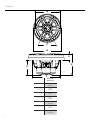 4
4
-
 5
5
-
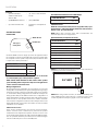 6
6
-
 7
7
-
 8
8
-
 9
9
-
 10
10
-
 11
11
-
 12
12
-
 13
13
-
 14
14
-
 15
15
-
 16
16
-
 17
17
-
 18
18
-
 19
19
-
 20
20
-
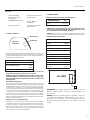 21
21
-
 22
22
-
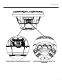 23
23
-
 24
24
-
 25
25
-
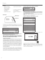 26
26
-
 27
27
-
 28
28
-
 29
29
-
 30
30
-
 31
31
-
 32
32


Rockford Fosgate Element Ready M2D2-10I Installation & Operation Manual
- Tipo
- Installation & Operation Manual
- Este manual también es adecuado para
en otros idiomas
- français: Rockford Fosgate Element Ready M2D2-10I
- italiano: Rockford Fosgate Element Ready M2D2-10I
- English: Rockford Fosgate Element Ready M2D2-10I
- Deutsch: Rockford Fosgate Element Ready M2D2-10I
Artículos relacionados
-
 Rockford Fosgate M1D4-10 Manual de usuario
-
 Rockford Fosgate M2 ELEMENT READY M2D2-10SB Manual de usuario
-
 Rockford Fosgate ELEMENT READY M0-65 Manual de usuario
-
Rockford Fosgate M1WL-65MB Instrucciones de operación
-
Rockford Fosgate M2WL-10H El manual del propietario
-
Rockford Fosgate PunchPM282HW-B Installation & Operation
-
 Rockford Fosgate M2WL-8 Manual de usuario
-
Rockford Fosgate M2-8HB Installation & Operation Manual
-
 Rockford Fosgate T1S1-10 El manual del propietario
-
 Rockford Fosgate PMX-1R El manual del propietario


