Paslode 515600 Manual de usuario
- Categoría
- Pistola de clavos
- Tipo
- Manual de usuario
Este manual también es adecuado para

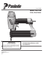
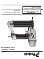
MODEL
T200-F18P
18 Ga. Brad Nailer
IMPORTANT!
DO NOT DESTROY
It is the customerʼs responsibility to have all
operators and service personnel read and
understand this manual.
OPERATING MANUAL AND
SCHEMATIC
P
Part# 515600
515610-2
08/17
PRINTED IN U.S.A.
© 2017, Illinois Tool Works Inc.

2
INTRODUCTION
The PASLODE
®
T200-F18P
Brad Nailer is a quality-built tool designed for use in residential
trim applications. This tool will deliver efficient, dependable performance when used according
to the manufactures guidelines. Please study this manual including the safety instructions to
fully understand the operation of this tool.
TOOL AND FASTENER SPECIFICATIONS ....................................................... 3
SAFETY INSTRUCTIONS ...................................................................................
TOOL OPERATION .............................................................................................. 5
EXPLODED VIEW AND SPARE PARTS LIST ............................................. 10- 1 1
ACCESSORIES ..................................................................................................
4
12
.
.
TOOL WARRANTY AND LIMITATIONS
Paslode warrants that newly purchased power
fastening tools, parts and accessories will be free
from defects in material and workmanship for the
period shown below, after the date of delivery to
the original user.
90 DAY LIMITED WARRANTY
A 90-day warranty will apply to all parts, except
those which are specifically covered by an extended
warranty.
EXTENDED LIMITED WARRANTY FOR ONSITE
CONSTRUCTION APPLICATIONS
A
one year warranty will apply to all housing and cap
assembly castings. A six month warranty will apply
to all magazine parts.
NORMAL WEARING PARTS
The following parts are considered normal wearing
parts and are not under warranty:
•
Bumper
•
Driver Blade
•
”O” Rings
•
Piston Rings
WARRANTY STATEMENT
This warranty is limited to tools sold and service requested
in the United States. To obtain information on warranty
service in the United States, refer to the Service Center
listing that was provided with your tool.
Paslode's sole liability hereunder will be to replace any part
or accessory which proves to be defective within the specific
time period. Any replacement part or accessory provided in
accordance with this warranty will carry a warranty for the
balance of the period of warranty applicable to the part it
replaces. This warranty does not apply to part replacement
required due to normal wear.
This warranty is void as to any tool which has been subjected
to misuse, abuse, accidental or intentional damage, use with
fasteners,not meeting
Paslode specification, size, or quality,
repaired with other than genuine
damaged in transit or handling, or
has been altered or repaired in a
from the performance of the tool.
PASLODE MAKES NO WARRANTY, EXPRESSED OR
IMPLIED, RELATING TO MERCHANTABILITY, FITNESS, OR
OTHERWISE, EXCEPT AS STATED ABOVE, and Paslode's
liability AS STATED ABOVE AND AS ASSUMED ABOVE is
in lieu of all other warranties arising out of, or in connection
with, the use and performance of the tool, except to the extent
other wise provided by applicable law. PASLODE SHALL IN
NO EVENT BE LIABLE FOR ANY DIRECT, INDIRECT, OR
CONSEQUENTIAL DAMAGES, INCLUDING, BUT NOT
LIMITED TO, DAMAGES WHICH MAY ARISE FROM LOSS
OF ANTICIPATED PROFITS OR PRODUCTION, SPOILAGE
OF MATERIALS, INCREASED COST OF OPERATION, OR
OTHERWISE.
improperly maintained,
Paslode replacement parts,
which, in Paslode's opinion,
way that affects or detracts
Paslode reserves the right to change specifications, equipment, or
designs at any time without notice and without incurring obligation.

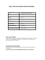
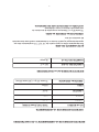
MODEL NO.
T200-F18P (Part # 515600)
HEIGHT 10.63"
WIDTH 2.56"
LENGTH 10.04"
WEIGHT 2.9lbs.
NAIL LENGTH "2 - "8/5
SHANK DIAMETER
18 gauge
OPERATING PRESSURE 80 to 120 psi
TOOL AIR FITTINGS:
This tool uses a 1/4” N.P.T. male plug. The inside diameter should be .28” (7mm)
or larger. The fitting must be capable of discharging tool air pressure when
disconnected from the air supply.
OPERATING AIR PRESSURE:
80 to120 psi. Select the operating air pressure within this range for best tool
performance.
DO NOT EXCEED THIS RECOMMENDED OPERATING PRESSURE.
TOOL AND FASTENER SPECIFICATIONS
3

4
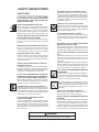
WARNING
Failure to follow any of the above instructions could result in severe personal
injury to tool user and bystanders or cause damage to tool and property.
SAFETY INSTRUCTIONS
SAFETY FIRST
These safety instructions provide information necessary
for safe operation of Paslode
tools. DO NOT
ATTEMPT
TO OPERATE
THE
TOOL UNTIL
YOU READ AND
UNDERSTAND ALL SAFETY PRECAUTIONS AND
MANUAL INSTRUCTIONS.
WEAR EYE AND HEARING PROTECTION
Always wear hearing and eye protection devices, that
conform to ANSI Z87.1 requirements, when operating
or working in the vicinity of a tool. As an employer you
are responsible for enforcing the use of eye protection.
Wear hard hats in environments that require their use.
THE TOOL MUST BE USED ONLY FOR THE PUR-
POSE FOR WHICH IT WAS DESIGNED
Do not throw the tool on the floor, strike the housing in
any way or use the tool as a hammer to knock material
into place.
NEVER ENGAGE IN HORSEPLAY WITH THE TOOL
The tool is not a toy so do not use it like one. Never
engage in horseplay with the tool or point it at yourself
or any other person, even if you think it is not loaded.
NEVER ASSUME THE
TOOL IS EMPTY
Check the magazine for fasteners that may be left in the
tool. Even if you think the tool is empty or disconnected,
never point it at anyone or yourself. Unseen fasteners
could fire from the tool.
NEVER CLAMP THE TRIGGER IN A LOCKED OR
OPERATING POSITION
The trigger of the tool must never be tampered with,
disabled or clamped in a locked or operating position
since this will cause the tool to drive a fastener any
time
the work contacting element depressed.
DO NOT LOAD FASTENERS WITH THE AIR LINE
CONNECTED, OR WITH THE TOOL TRIGGER OR
WORK CONTACTING ELEMENT DEPRESSED
When loading fasteners into the tool be sure you
disconnect the air line and that you do not depress
the trigger or work contacting element.
OPERATE THE TOOL ONLY ON A WORKPIECE
The tool should be operated only when it is in contact
with the workpiece. Even then you should be careful
when fastening thin material or working near the edges
and corners of the workpiece since the fasteners may
drive through or away from the workpiece.
DO NOT DISABLE OR REMOVE THE WORK
CONTACTING ELEMENT
This tool is equipped with a safety mechanism, called a
a work contacting element, to help prevent accidental
firing. Never tamper with, disable or remove the work
contacting element. Do not use the tool unless the work
contacting element is working properly.The tool could
fire unexpectedly.
®
DISCONNECT THE TOOL WHEN NOT IN USE
Always disconnect the tool from the air line when it
is not in use, when you leave the work area or when
moving the tool to a new location. The tool must
never be left unattended because people who are
not familiar with the tool might handle it and injure
themselves or others.
CARRY THE TOOL ONLY BY THE HANDLE
Always carry the tool by the handle only. Never carry
the tool by the air hose or with the trigger depressed
since you could drive a fastener unintentionally and
injure yourself or someone else.
DO NOT WEAKEN THE TOOL HOUSING
The tool housing is a pressure vessel and should never
be weakened by having your companyʼs name, area of
work or anything else stamped or engraved into its
surface.
DISCONNECT THE TOOL WHEN PERFORMING
REPAIRS AND CLEARING JAMS
Never attempt to clear a jam or repair a tool unless you
have disconnected the tool from the air line and
removed all remaining fasteners from the tool.
ALWAYS USE THE PROPER FITTING FOR THE
TOOL
Only MALE pneumatic type air connectors should be
fitted to the tool, so that high pressure air in the tool is
vented to atmosphere as soon as the air line is dis-
connected.
NEVER install FEMALE quick disconnect couplings on
the tool. Female couplings will trap high pressure air in
the tool when the air line is disconnected, leaving the
tool charged and able to drive at least one fastener.
DO NOT EXCEED THE MAXIMUM RECOMMENDED
AIR PRESSURE
.erusserp ria dednemmocer eht
ta ylno loot eht etarepO
Do not exceed the maximum air pressure marked on
the tool. Be sure the air pressure gauge is operating
properly and check it at least twice a day.
Never use any bottled air or gases such as oxygen to
operate the tool since they could cause the tool to
explode. Do not operate in explosive atmospheres such
INSPECT TOOL FOR PROPER OPERATION
.deriuqer sa etacirbul dna yliad tsael ta loot eht naelC
Never operate a dirty or malfunctioning tool.
USE ONLY PASLODE RECOMMENDED PARTS AND
FASTENERS
Use only parts and fasteners specifically designed and
recommended by Paslode
for use in the tool and for
work to be done. Using unauthorized parts and fasteners
or modifying the tool in any way creates dangerous
situations. Replace all missing warning labels---refer
to tool schematic for correct placement and part Number.
as in the presents of flammable liquids, gases, or com-
bustible dust.
®
®

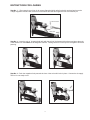
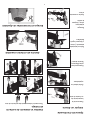
Step No. 1
– Disconnect the tool from its air source.Grasp the finish nailer firmly with one hand and press the
rear of the
handle and slide the magazine cover back towards you.
Step No. 2 – Insert the strip of 18 gauge brad nails with the point of the fastener facing down and place the point
of the fastener into the bottom of the magazine channel. Placing fasteners on the top of the magazine will cause
jamming.
Step No. 3 – Push the magazine firmly towards the front of the tool until it locks in place.
Connect the air supply.
The tool is now ready to use..
INSTRUCTIONS FOR LOADING
5
orange magazine release button at the
Press release.
Disconnect air
Slide cover

6
Successive (Bounce) Driving
■ Grasp the handle firmly.
■ Squeeze the trigger and move the tool along the work-
piece with a bouncing motion, depressing the work con-
tacting element at the points where you want to insert a
fastener.
■ Keep the trigger depressed and continue to bounce the
work contacing element against the workpiece, positioning
the tool above as carefully as possible.
■ When the desired number of fasteners have been driven,
release the tool trigger to avoid unintentional fastener dis-
charge.
Sequential Operation - (Gray Trigger)
The sequential operating kit prevents successive or
“bounce” driving.
■
Depress the work contacting element and hold it against
the work surface before pulling the trigger.
■
After each fastener is driven, completely release the trig-
ger and lift the tool from the work surface.
TOOL OPERATION -
continued
Use only fasteners that meet Paslode specifications.
Use of fasteners that do not meet Paslode specifica-
tions can result in damage to the tool or injury to the
operator or bystanders.
WARNING
®
®
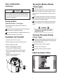
Precision Placement Driving
(Orange Trigger)
■
Grasp the tool handle firmly and hold the bottom of the
work contacting element firmly against the workpiece until
it is completely depressed.
■ Squeeze the trigger to drive the fastener.
■ Lift the tool from the workpiece.
■ Repeat the procedure for the next fastener.
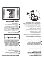
Driving of Nails
■
A
B
C
CHANGING THE TRIGGER
1. Disconnect the tool from air source.
2. Remove trigger step pin rubber retaining ring ( A ).
3. Remove trigger step pin (
B
).
4. Remove sequential trigger assembly
C (Gray, part # 576918) and spring.
5. Install contact trigger
D (part# 576917,
Orange)
with spring and align hole and reinsert Trigger
step pin.
6. Reinstall rubber retaining ring and
check for correct operation.
D
Adjust the Depth of Drive
(Orange Trigger)

MAINTENANCE
Paslode
®
tools are built for ease of maintenance. A few
simple details will assure trouble-free operation and long
tool life. Anyone who uses or maintains the tool must read
the safety and maintenance instructions. Study the sche-
matic drawing before starting any repairs on the tool.
Air-operated tools must be inspected periodically, and worn
or broken parts must be replaced to keep the tool operating
safely and efficiently. Also the items on the maintenance
chart must be checked often.
Cold Weather Care
When temperatures are below freezing, tools should be
kept warm by any convenient, safe method. If this is not
possible, the following procedure should be used to warm
up the tools.
Reduce the regulated air pressure to 30 psi.
Remove all fasteners from the tool.
Collect an air line and blank fire the tool. The reduced
air pressure will be enough to free-fire the tool. Slow speed
operation tends to warm up the moving parts. Slowing up
the piston helps the bumper and the O-rings to become
pliable.
Once the tool is warmed up, readjust the regulator to
the proper working pressure and reload the tool.
Tool operators working outdoors or in unheated areas in
extremely cold temperatures should also:
Use Paslode pneumatic oil with antifreeze in the
lubricator, Part No. 219090 (8oz.)
Once a week, depending on the amount of tool use,
take the tool apart and wash away any sludge with
degreaser cleaner (Paslode Part No. 219086) to
keep the tool operating efficiently.
Cleaning the air-operated tools with solvents removes the
thin coating of grease applied to the cylinder wall and
O-rings at the factory. To replace this coating of grease,
use Chemplex grease (Paslode Part No. 403734).
Open the drain on the air compressor tank to drain any
moisture at least daily in extremely cold or humid weather.
A few ounces of anti-freeze in the tank will keep the air
free of frost.
Testing the Tool After Servicing
After replacing any part or parts, it is important to check
the tool for proper operation. This ensures that the tool
was put together correctly, is safe to use, and will perform
the job properly.
Ensure that all hardware is tight.
Ensure that the work contacting element is installed
correctly in relation to the trigger, and that both parts
move freely.
Ensure that the magazine is properly attached.
Ensure that the required safety information on the tool
is legible.
Use only Paslode approved fasteners in the tool, and
ensure that they are correct for the application.
Ensure that a male air fitting is securely connected to
the tool.
Test the tool by driving fasteners into a workpiece
identical to the tool's application.
Check the tool for air leaks during testing and for the
proper sequence of operation.
Ensure that all fasteners are driven to the same depth
and that the crown of the fastener is flush with the
workpiece.
Tool Lubrication
It is most important that the tool be properly lubricated by
keeping the air line lubricator filled and correctly adjusted.
Without proper lubrication the tool will not work properly
and parts will wear prematurely.
Use the proper lubricant in the air line lubricator. The
lubricator should be of low air flow or changing air flow
type, and should be kept filled to the correct level. Use
only Paslode recommended lubricants. Substitutes may
harm the rubber compounds in the tools O-rings and other
rubber parts. Paslode Part No. 403720 is a pneumatic
lubricating oil specially made for pneumatic applications.
If a filter/regulator/lubricator is not installed on the air
system, air operated tools should be lubricated at least
once a day with 6 to 20 drops of oil, depending on the
work environment, directly through the male fitting in the
tool housing.
Most minor problems can be resolved quickly and easily
using the maintenance table that follows. If problems
persist, contact your Paslode dealer for assistance.
7

8
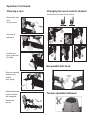
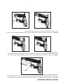
Clearing a Jam
Reversable belt hook
Tooless Ajustable Exhaust
Disconnect tool
from
its air source.
Remove all
fasteners.
Unlatch the
front guide and
lift open.
Remove jammed
fastener and
relatch
front guide.
Reload fasteners,
close and latch
the magazine.
Reconnect
the air.
Changing the work contact element.
Operation Continued:
Disconnect tool from its air source.

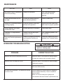
OPERATOR TROUBLESHOOTING
PROBLEM CORRECTIVE ACTION
Fasteners will not drive completely into wood.
Fasteners drive too deeply into wood.
Fastener jams in nose of tool.
Tool skips during operation - no fasteners are driven
from time to time.
Adjust the
depth of drive adjustment (retract length).
Adjust the
depth of drive adjustment (extend length).
Open front guide latch, release jammed fastener,
and close latch securely.
Check magazine for proper fasteners. Magazine
follower should slide freely. Clean as needed to
remove debris.
Make sure correct fasteners are being used.
Use fasteners that meet Paslode
®
specifications only.
9
Reduce air pressure.
Increase air pressure (do not exceed 120 psi).
CAUTION
Disconnect the tool when performing
repairs or clearing jams.
MAINTENANCE
Add several drops of pneumatic
oil into the air fitting.
Check that all screws on tool
are tight.
Keep work contacting elelment
working properly.
Keep magazine and feeder
mechanism clean.
Lubricate "O" rings that are
replaced.
Use only Paslode replacement
parts.
WOHYHWNOITCA
Keep tool lubricated.
Prevent air leakage and pro-
mote efficient operation.
Promote operator safety and
efficient tool operation.
Prevent jamming of fasteners.
Assure long life and proper
operation of tool.
Keep tool operating efficiently
and maintain Paslode tool
warranty.
Use Paslode pneumatic
tool lubricant. Part No.
403720.
Check screws daily.
Inspect and blow clean daily
and check for proper operation.
Blow clean daily.
Use Chemplex grease, Part
No. 403734.
Order any replacement parts
needed from Paslode Dealer.

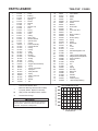
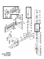
10
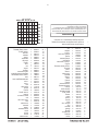
PARTS LEGEND
T200-F18P
515600
1 617539 1 Screw
2 617558 1 Bushing
3 617504 1 Air Deflector
4 576913 1
5
617535 4 Washer
6
617489 1 Cap
7
617550 1 Gasket, Cap
8
617548 1 Seal
* 9
617519 1 Spring
10
617521 1 O-Ring
*11
617510 1 Valve
12
13
617507 1 Piston Stop
14
617552 1 Restrict Washer
15
617551 1 Cylinder Seal
16
17
18
617523
1
*20
*21
22
24
617522 1 O-Ring
26
1 Joint Guide
27
617526 1 O-Ring
30
576916
1 Spring
28
576915 1
29
32
Trigger, Sequential
33
617537
1
34
617553
1 Safety Bracket
35
576919
1 Spring
37
617544
1
Logo-2
617549
1
40
617513 4
Screw
41
576922
1
Screw
42
576923
1
Plate
43
576966
2
Spring Washer
576925 1
Movable Magazine Unit
47
48
576926 1 Lock Lever Unit
49
576927 1 Pin
50
576928 1 Work Contact A
51
576929 1 Pusher
52
617520 1
53
576967 2 Spring
54
617538 2 Screw
55
617511 1 Rear Plate
56
617536
2
57
617556 1
58
617512 1
Spring
59
576930 1
Air Plug
61
576931 1 Label, Trigger Sequential
62
576934 1 Magazine Unit Sequential
63
576935 1 Work Contact B
64
576936 1 Support
65
617540 1 Screw
66
617541 1 Pin
67
68
576937 1
69
576938 1
End Cap
70
576939 1
Belt Hook
19
576914
1
Piston Assembly
72
617534 1
Guide, Spring
73
576940 1
Screw
74
60
617496 1
Rail
23
617508
*
Denotes Normal Wear Items
**
Make sure Warning Label (Part No.515620)
is properly affixed. Replace if necessary.
▲
Apply Loctite 242 (Blue) Part N o. 093500
Denotes New Change
WARNING
All parts must be periodically inspected and replaced if
worn or broken. Failure to do this can affect the toolʼs
operation and present a safety hazard.
AIR CONSUMPTION CHART
AIR CONSUMPTION-CFM FASTENER
AIR PRESSURE-PSIG
25
36
576920
1 Safety Lever Unit
71
576979 1
.040
.035
.020
.025
.030
120
.010
.015
11010090807060
➔
**
.034
617488 1
Trigger Valve Assembly
Housing
Spring Pin
Gasket
Front Plate
Guide, Spring
Nut
Cover
Cover
Washer
617509 1
617555
1
Lock
®
.
*
*
45
617530 1
PIN
*
*
617547 1
Washer
46
Spring
617527 1 O-Ring
*
617533
4
Screw
*
*
617524 1
617503 1 Collar
617525 1 O-Ring
617506 1 Bumper
*
617505 1 Cylinder Sleeve
617545 1 Logo-1
44
576924
2
Screw
*
O-Ring
75
515620 1
Label, Safety Warning
O-Ring
576918 131
38
617529
1
Pin
39 576921
1 Driver Guide

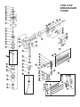
11
1
2
3
4
5
6
7
8
9
10
11
12
13
14
15
16
19
20
21
22
23
24
25
69
70
71
72
40
73
68
67
66
65
40
64
63
37
36
38
61
60
39
40
41
42
44 43
50
45
46
47
48
49
51 52
53
58
54 55 56 57
26
27
28
29
30
31
32
33
34
35
17
18
59
74
62
A
B
T200-F18P
BRAD NAILER
515600

P
L
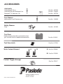
ubricants
027304 .oN traP.zo 61 liO gnitacirbuL
090912 .oN traP
.zo 8 ezeerftinA htiw liO gniacirbuL
437304 .oN traP.bl1 tnacirbuL 017 xelpmehC
Tool Cleaner
680912 .oN traP
.sloot edolsaP lla rof renaelc laedI
Safety Glasses
382104 .oN traP
raelC
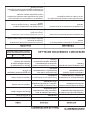
ACCESSORIES
An Illinois Tool Works Company
155 Harlem Avenue
Glenview, IL 60025
© 2017, Illinois Tool Works Inc.
Tool Case
Handy carrying case that conveniently stores
your
tool
515615 .oN traP
.seirossecca lanoitidda rof moor htiw
Work Contact Element A B
576928 .oN traP
576935 .oN traP
A
B
Contact Trigger (Orange)
576917 .oN traP
Tool Case Latch
617559 .oN traP

L
ubricantes
Aceite Lubricante 16 oz.
Pieza No. 403720
Aceite Lubricante con Anticongelante 8 oz.
Pieza No. 219090
Lubricante Chemplex® 710 1lb.
Pieza No. 403734
Desengrasador
Pieza No. 219348
Lentes de Seguridad
Claros
Pieza No. 401382
ACCESORIOS
El limpiador ideal para todas las herramientas Paslode.
12
PRINTED IN U.S.A.
© 2017, Illinois Tool Works, Inc.
P
An Illinois Tool Works Company
155 Harlem Avenue
Glenview, IL 60025
®
Maleta de Transporte para Herramientas
515615
A B
576928 Pieza No.
576935 Pieza No.
A
B
Contacto Trigger (anaranjado)
576917
Maletín de Herramientas
Pestillo de Reemplazo
617559 Pieza No.
Pieza No.
Pieza No.
Elemento de Contacto de Trabajo
Práctico estuche que almacena convenientemente
su herramienta con espacio para accesorios adicionales.

11
1
2
3
4
5
6
7
8
9
10
11
12
13
14
15
16
19
20
21
22
23
24
25
69
70
71
72
40
73
68
67
66
65
40
64
63
37
36
38
61
60
39
40
41
42
44 43
50
45
46
47
48
49
51 52
53
58
54 55 56 57
26
27
28
29
30
31
32
33
34
35
17
18
59
74
62
A
B
T200-F18P
BRAD NAILER
515600

10
LISTA DE PIEZAS,
T200-F18P
515600
1 617539 1 Screw
2 617558 1 Bushing
3 617504 1 Air Deflector
4 576913 1
5
617535 4 Washer
6
617489 1 Cap
7
617550 1 Gasket, Cap
8
617548 1 Seal
* 9
617519 1 Spring
10
617521 1 O-Ring
*11
617510 1 Valve
12
13
617507 1 Piston Stop
14
617552 1 Restrict Washer
15
617551 1 Cylinder Seal
16
17
18
617523
1
*20
*21
22
24
617522 1 O-Ring
26
1 Joint Guide
27
617526 1 O-Ring
30
576916
1 Spring
28
576915 1
29
32
Trigger, Sequential
33
617537
1
34
617553
1 Safety Bracket
35
576919
1 Spring
37
617544
1
Logo-2
617549
1
40
617513 4
Screw
41
576922
1
Screw
42
576923
1
Plate
43
576966
2
Spring Washer
576925 1
Movable Magazine Unit
47
48
576926 1 Lock Lever Unit
49
576927 1 Pin
50
576928 1 Work Contact A
51
576929 1 Pusher
52
617520 1
53
576967 2 Spring
54
617538 2 Screw
55
617511 1 Rear Plate
56
617536
2
57
617556 1
58
617512 1
Spring
59
576930 1
Air Plug
61
576931
1 Label, Trigger Sequential
62
576934 1 Magazine Unit Sequential
63
576935 1 Work Contact B
64
576936 1 Support
65
617540 1 Screw
66
617541 1 Pin
67
68
576937 1
69
576938 1
End Cap
70
576939 1
Belt Hook
19
576914
1
Piston Assembly
72
617534 1
Guide, Spring
73
576940 1
Screw
74
60
617496 1
Rail
23
617508
**
25
36
576920
1 Safety Lever Unit
71
576979 1
.040
.035
.020
.025
.030
120
.010
.015
11010090807060
.034
617488 1
Trigger Valve Assembly
Housing
Spring Pin
Gasket
Front Plate
Guide, Spring
Nut
Cover
Cover
Washer
617509 1
617555
1
Lock
.
*
*
45
617530 1
PIN
*
*
617547 1
Washer
46
Spring
617527 1 O-Ring
*
617533
4
Screw
*
*
617524 1
617503 1 Collar
617525 1 O-Ring
617506 1 Bumper
*
617505 1 Cylinder Sleeve
617545 1 Logo-1
44
576924
2
Screw
*
O-Ring
75
515620 1
Label, Safety Warning
O-Ring
576918 131
38
617529
1
Pin
39 576921
1 Driver Guide
*
Indica piezas de desgaste normal.
Asegure que la Etiqueta de Advertencia (515620)
este bien pegada. Reemplaze si es necesario.
ADVERTENCIA
Todas las piezas deben ser inspeccionadas periódicamente
y ser reemplazadas si estan gastadas o rotas. Falta de hacer
esto puede afectar el funcionamiento de la herramienta y
presentar un riesgo de seguridad.
**
TABLA DE CONSUMO DE AIRE
CONSUMO DE AIRE -SCFM SUJETADOR
PRESIÓN DE AIRE

DETECCION Y CORRECCION DE FALLAS
9
PROBLEMA SOLUCIÓN
Los sujetadores no penetran completamente en la
madera.
Los sujetadores penetran demasiado en la madera.
Los sujetadores se acumulan en la punta de la her
ramienta.
La herramienta “salta” mientras está funcionando; de
vez en cuando no impulsa sujetadores.
Aumente la presión de aire (no debe exceder 120 psi).
Reduzca la presión de aire.
Compruebe si el cargador tiene los sujetadores apro-
piados. El transportador debe deslizarse sin dificultad.
Límpielo para quitar cualquier suciedad.
Verifique que se usen los sujetadores apropiados.
Use solamente sujetadores que reúnan las especifica-
ciones de Paslode.
PRECAUCIÓN
Desconecte la herramienta al hacer cualquier
reparación o eliminar cualquier obstrucción.
®
Ajuste la profundidad de ajuste del accionamiento
(longitud de retracción).
Ajuste la profundidad del ajuste del accionamiento
(alargar la longitud).
Abra el pestillo de la guía delantera, suelte el
sujetador atascado, Y cierre el seguro de forma
segura.
MANTENIMIENTO
ACTIVIDAD POR QUE COMO
Mantenga lleno el lubricador.
Verifique que todos los tornillos de
la herramienta estén apretados.
Revise si el elemento de contacto
funciona correctamente.
Mantenga limpios los mecanismos
del cargador y del alimentador.
Lubrique los anillos-o que se
hayan reemplazado.
Use solamente piezas de repuesto
Paslode.
Para mantener lubricada la
herramienta.
Para evitar pérdidas de aire y
asegurar el buen funcionamiento
de la herramienta.
Para promover la seguridad del
operador y el buen funcionamiento
de la herramienta.
Par prevenir que se obstruyan los
sujetadores.
Para prolongar la vida de la
herramienta y su funcionamiento
adecuado.
Para que la herramienta continúe
funcionando eficientemente y
mantener vigente la garantía de
Paslode.
Llene con lubricante neumático
N° 403720 (474 ml).
Revise los tornillos a diario.
Límpielo con aire a diario.
Límpielos con aire a diario.
Use grasa lubricante Chemplex
N° 403734.
Solicite al representante de
Paslode cualquier pieza de
repuesto que necesite.
TABLA DE MANTENIMIENTO
®
®

8
Limpiar un Atasco
Gancho de cinturón reversible
Escape sin herramientas de Ajustable
Desconecte la
herramienta de
su fuente de aire.
Quite todos los
sujetadores.
Desenganchar la
guía delantera y
levante abierto
Retire el sujetador
atascado y cierre
y bloquee la guía
delantera.
Recargar
sujetadores,
cerrar y bloquear
la revista.
Vuelva a conectar
el aire.
Cambiar el elemento de contacto
de trabajo.
Operación Continuada:
Desconecte la herramienta de su fuente de aire.

28
MANTENIMIENTO
7
El mantenimiento de cualquier herramienta Paslode es
simple. Su funcionamiento sin problemas y la prolongación
de la vida de la herramienta se logran siguiendo un sencil-
lo procedimiento. Las personas encargadas de usar y
mantener la herramienta deben leer las instrucciones de
seguridad y mantenemiento. Estudie los diagramas antes
de hacer cualquier reparación.
Las herramientas neumáticas deben revisarse periódica-
mente, y se deben cambiar las piezas gastadas o dete
-
rioradas para que la herramienta siga funcionando con
eficiencia y sin peligro. Además, se debe revisar la tabla
de mantenimiento frecuentemente.
Cuando Hace Mucho Frio
Cuando la temperatura es inferior a la de congelamiento,
las herramientas deben mantenerse a la temperatura
ambiente por el método más seguro y conveniente. De lo
contrario, aconsejamos seguir el siguiente procedimiento
para calentar las piezas de la herramienta.
■ Disminuya la presión regulada del aire a 30 psi.
■ Quite todos los sujetadores de la herramienta.
■
Conecte una línea de aire y dispare la herramienta
sin clavos. La presión reducida del aire será suficiente
para lograrlo. El funionamiento a poca velocidad
tiene la tendencia de calentar las partes movibles.
Disminuyendo la velocidad del pistón le da cierta
elasticidad al amortiguador y los anillos-o.
■
Una vez que la herramienta se haya calentado, ajuste
nuevamente el regulador a la presión apropiada para
trabajar y cargue de nuevo la herramienta.
■ Los operadores que trabajen al aire libre o en áreas
sin calefacción con temperaturas extremadamente
frías también tienen que usar en el lubricador el
aceite neumático con anticongelante N° 219090
(8 oz.).
■
Una vez por semana, según el uso que le dé a su
herramienta, desármela y lávela con el solvente N°
219348, para eliminar cualquier suciedad y asegurar
que la herramienta siga funcionando bien.
Al usar solventes para limpiar herramientas neumáticas
se destruye la delgada capa de grasa lubricante, que se
aplica en la fábrica, de la pared del cilindro y de los anil-
los-o. Use grasa Chemplex N° 403734 para reemplazar
la capa de grasa lubricante.
PRECAUCIÓN
Nunca dispare la herramienta sin clavos a
alta presión.
PRECAUCIÓN
Nunca use queroseno ni ningún solvente
inflamable par limpiar la herramienta.
■ Abra, por lo menos diariamente, el drenaje del tan-
que del compresor del aire para eliminar cualquier
humedad, cuando haga mucho frío o el grado de
humedad sea muy alto. Poniendo una pequeña
cantidad de descongelante en el tanque evitará que
la humedad se congele.
Probar la Herramienta Después de Darle
Servicio
Después de reemplazar una o más piezas, es importante
comprobar si la herramienta funciona como es debido.
Esto asegura que todas las piezas estén puestas cor-
rectamente, que la herramienta esté segura y que fun
-
cione correctamente.
■ Verifique que ninguna pieza esté floja.
■
Compruebe que el elemento de contacto haya sido
correctamente instalado en relación con el gatillo y
que ambas piezas se muevan libremente.
■ Verifique que el cargador esté colocado
correctamente.
■
Verifique que la información sobre seguridad, que
está en la herramienta, sea legible.
■
Use solamente sujetadores aprobados por Paslode
y compruebe que sean los apropiados para su
aplicación.
■
Verifique que se haya conectado firmemente un
adaptador macho a la herramienta.
■ Pruebe la herramienta impulsando sujetadores en
unmaterial de trabajo idéntico al de la aplicación.
■ Verifique que no haya pérdidas de aire en la her-
ramienta durante las pruebas y revise la secuencia
apropiada de funcionamiento.
■
Asegure que todos los sujetadores sean impulsados
a la misma profundidad y que la cabeza del sujta-
dor esté al ras con el material de trabajo.
Lubricación de la Herramienta
Es muy importante lubricar la herramienta correctamente,
manteniendo lleno el lubricador de la línea de aire y
correctamente regulado. Sin la lubricación apropiada, la
herramienta no funcionará como es debido y sus piezas
se gastarán prematuramente.
Use el lubricante apropiado en el lubricador de la línea de
aire. El lubricador debe ser para corriente de aire baja o
variable, y tiene que estar lleno hasta el nivel apropiado
por Paslode porque otros lubricantes podrian dañar el
caucho de los anillos-o y otras piezas de caucho. El lubri
-
cante N° 403720 (474 ml) es un aceite lubricante espe
-
cialmente diseñado para aplicaciones neumáticas.
Si no se instala un filtro/regulador/lubricador en el siste-
ma neumático, las herramientas neumáticas deben ser
lubricadas, por lo menos, diariamente, poniendo entre 6
y 20 gotas de aceite, según sea el tipo de trabajo que se
realice, directamente a través del adaptador macho.
Usando la siguiente tabla de mantenimiento es posible
resolver rápidamente y fácilmente la mayoría de los pe
-
queños problemas. Si un determinado problema persiste,
comuniquese con el representante de Paslode.
®
®
®
®
®

6
La conducción de clavos
A
B
C
CAMBIANDO EL DISPARADOR
1. Desconecte la herramienta de la fuente de aire.
2. Retirar el anillo de retención
3. Retire el pasador del gatillo (B)
4.Retire el conjunto de gatillo secuencial (C)
(Gris, Parte # 576918) y resorte.
5. Instalar Contacto gatillo (D),naranja, parte
#576917)con resorte y alinee el orificio y
vuelva a
insertar el pasador de paso del gatillo.
6. Vuelva a instalar el anillo de retención de caucho
y compruebe su correcto funcionamiento.
D
Ajustar la profundidad
de clavado
Impulsos sucesivos (de rebote)
■ Tome la herramienta firmemente por
el mango.
■ Apriete el gatillo y mueva la
herramienta a lo largo del material de
trabajo con un movimiento de rebote,
oprimiendo el elemento de contacto
en los lugares donde quiera colocar
un sujetador.
■
Manteniendo apretado el gatillo,
continúe haciendo rebotar el elemento
de contacto contra el material de trabajo,
colocando cuidadosamente la herramienta.
■
Una vez que haya colocado todos los
sujetadores necesarios, deje de oprimir el
gatillo para
evitar que salgan más.
PELIGRO
ninguna otra cosa que no sea la mano.
No sujete ni sostenga el gatillo con
Colocación precisa
■
Tome firmamente la herramienta por el
mango y sosténgala de modo que el base del
elemento de contacto quede bien apoyada en
el material de trabajo.
■
Apriete el gatillo para disparar el sujetador.
■
Separe la herramienta del material de
trabajo.
■
Repita el mismo procedimiento con el
próximo sujetador.
Funcionamiento en secuencia
El juego de funcionamiento en secuencia
evita los impulsos sucesivos o "de rebote".
■
Oprima el elemento de contacto y
manténgalo apoyado contra el material
de trabajo antes de apreter el gatillo.
■
Después de haber impulsado cada
sujetador, suelte completamente el gatillo
y levante la herramienta del material de
trabajo.
(Gatillo de Color Gris)
(Gatillo de color Naranja)
FUNCIONAMIENTO DE LA
HERRAMIENTA
(continuación)

INSTRUCCIONES DE CARGA
5
Presione soltar.
Tapa
deslizante
Paso No. 1 - Desconecte la herramienta de su fuente de aire. Sujete firmemente la clavadora de acabado con
una mano y presione el botón de liberación del cargador naranja en la parte posterior de la manija y deslice la
cubierta del cargador hacia usted.
Paso No. 3 - Empuje el cargador firmemente hacia la parte delantera de la herramienta hasta que encaje en su
lugar. Conecte el suministro de aire. La herramienta está lista para usar.
Paso No. 2 - Inserte la tira de clavos de calibre 18 con el punto de los sujetadores hacia abajo y coloque el
punto del sujetador en la parte inferior del canal del cargador. Colocar sujetadores en la parte superior de la
revista causará atascos.
Desconectar
el aire

PELIGRO
La falta de observación de cualquiera de estas instrucciones puede ser causa de graves
lesiones personales, tanto al operador de la herramienta comoa quienes estén cerca de
ella o de daños materiales o a la herramienta
.
Comuníquese con el representante de Paslode sobre la presentación de Programa de Alerta sobre
Seguridad.
LA SEGURIDAD ESTA PRIMERO
Estas instrucciones proporcionan la información necesatia para
el funcionamiento sin peligrode las herramientas Paslode. NO
trate de usar su herramienta hasta que no haya léido y en-
tendido todas las precauciones de seguridad y las instruc-
ciones de este manual.
PROTEJASE LOS OJOS Y LOS OIDOS
Use siempre el equipo adecuado para protegerse
los ojos y los oídos que sea conforme con ANZI Z87,
meintras usa una herramienta o trabaja cerca de una
herramienta en uso. Como empleador usted es respons-
able de imponer el usp del la porteccion de ojo. Lleve
sombreros duros en los ambientes que requieren su
uso.
USE SU HERRAMIENTA SOLAMENTE PARA EL
PROPOSITO CON QUE FUE DISEÑADA
No arroje la herramienta al suelo; no golpee el armazón ni la use
como un martillo.
NUNCA USE LA HERRAMIENTA PARA JUGUETEAR
Esta herramienta no es un juguete; por lo tanto no la trate como
tal. Nunca juguetee con ella, ni se apunte a usted mismo ni a
otra persona, aun cuando crea que no está cargada.
NUNCA ASUMAQUE LA HERRAMIENTA ESTA VACIA
Verfique que ho haya sujetadores en elcargador. Aun cuando
crea que está vacía o desconectada, nunca se apunte ni apunte
a otra persona con la herramienta, porque podría dispararse un
sujetador que no esté a la vista.
NUNCA SUJETE EL GATILLO EN LA POSICION DE
CIERRE O DE FUNCIONAMIENTO
Nunca se debe manipular indebidamente o dejar inoperante el
gatillo, o sujetarlo en la posición de cierre o defuncionamiento,
porque se podría disparar un sujetador al oprimirse el elemento
de contacto.
NO CARGUE SUJETADORES CUANDO LA LINEA DE
AIRE COMPRIMIDO ESTE CONECTADA, O CUANDO
EL GATILLO O EL ELEMENTO DE CONTACTO ESTE
OPRIMIDO.
Antes de cargar sujetadores en la herramienta, verifique que la
línea de aire comprimido esté desconectada y que ni el gatillo ni
el elemento de contacto estén oprimidos.
USE LA HERRAMIENTA SOLAMENTE SOBRE UN
MATERIAL DE TRABAJO
La herramienta debe funcionar sólo cuando esté en contacto
con el material de trabajo. Debe tener mucho cuidado cuando el
material sea delagado o trabaje cerca de las aristas del mismo,
porque los sujetadores podrían atravesar o salirse del material.
NO DEJE INOPERANTE NI QUITE EL ELEMENTO DE
CONTACTO
Esta herramienta está equipada con un mecanismo de seguri-
dad, llamado elemento de contacto, para prevenir cualquier disp-
aro accidental. Nunca manipule indebidamente, deje inoperante,
ni quite el elemento de contacto. No use la herramienta a menos
que dicho elemento funcione correctamente, porque podría
producirse un disparo imprevisto.
DESCONECTE LA HERRAMIENTA CUANDO NO
LA ESTE USANDO
Siempre desconecte la herramienta de la línea de aire
comprimido cuando no la esté usando o al dejar su lugar de
trabajo. Nunca la descuide, porque cualquier persona que no
esté familiarizada con ella podría lastimarse o lastimar otros.
TOME LA HERRAMIENTA SOLAMENTE POR EL
MANGO
Siempre tome la herramienta sólo por el mango. Nunca la
tome por la manguera o con el gatillo oprimido, porque se
podría disparar un sujetador y herirlo o herir a otra persona.
NO ALTERE EL ARMAZON DE LA HERRAMIENTA
El armazón de la herramienta es un recipiente a presión y nunca
se debe grabar en su superficie el nombre de su compañia, el
del área de trabajo, ni ningún otro detalle.
DESCONECTE LA HERRAMIENTA PARA HACER
REPARACIONES O ELIMINAR OBSTRUCCIONES
Nunca trate de eliminar obstrucciones o reparar una herra-
mienta sin haberla desconectado de la línea de aire compromido
y quitado todos los sujetadores.
USE SIEMPRE LOS ADAPTADORES APROPIADOS
PARA SU HERRAMIENTA
Se debe conectar a la herramienta solamente conectores
neumáticos MACHOS, para permitir que el aire de alta pre-
síon salga tan pronto como se desconecte la línea de aire
comprimido.
NUNCA coloque enlaces HEMBRAS de desconexíon rápida
en la herramienta, porque atrapan el aire a alta presíon al
desconectar la línea de aire comprimido, dejándola cargada y
lista para disparar por lo menos un sujetador.
NO EXCEDA LA PRESION NEUMATICA MAXIMA
RECOMENDADA
La herramienta debe funcionar sólo con la presíon neumática re-
comendada. No exceda la presíon neumática máxima marcada
en la herramienta. Verifique por lo menos dos veces al día que
el calibre de la presíon neumática funcione correctamente.
Nuna use aire o gases envasado, como el oxígeno, para hacer
funcionar la herramienta porque podrían hacer que explotara.
No haga funcionar en atmósferas explosivas.
INSPECCIONE LA HERRAMIENTA PARA LA OPERA-
CION APROPIADA
Limpie diariamente la herramienta y lubríquela como se re-
comienda. Nunca trate de hacer funcionar
una herramienta
sucia o defectuosa.
USE SOLAMENTE PIEZAS Y SUJETADORES RECO-
MENDADOS POR PASLODE
Use sólo piezas y sujetadores específicamente diseñados y
recomendados por Paslode para usar con esa herramienta
y para la tarea requerida. Si se usan piezas o sujetadores no
autorizados o se modifica de alguna forma la herramienta, se
pueden crear situaciones peligrosas. Vuelva a colocar todas
las etiquetas de precaucíon que flaten. Consulte el diagrama
de la herramienta sobre el número de cada parte y su ubli-
gación correcta.
INSTRUCCIONES DE SEGURIDAD
4

19
ESPECIFICACIONES DE LA HERRAMIENTA
NO. de MODELO T2OO-F18P (Pieza# 515600)
ALTURA 10.63”
ANCHO 2.56"
LONGITUD 10.04"
PESO 2.9 lbs.
PRESIÓN de OPERACIÓN 70 hasta 120 p.s.i. (6.2 hasta 8.3 bar)
ESPECIFICACIONES de los SUJETADORES
ACOPLAMIENTO DE AIRE:
Esta herramienta utiliza un tapón macho de 1/4" N.P.T. El acoplamiento debe ser
capaz de descargar la presión de aire en la herramienta cuando sea desconectada
del suministro de aire.
OPERACION de PRESIÓN de AIRE:
70 hasta120 p.s.i. Seleccione una presión de aire dentro de
esta gama para obtener el mejor rendimiento.
NO EXCEDA LA PRESIÓN DE AIRE RECOMENDADA.
LONGITUD DEL CLAVO 5/8" to 2”
DIAMETRO DEL TALLO 18 gauge
ESPECIFICACIONES DE LA HERRAMIENTA Y LOS SUJETADORES
3

18
INTRODUCCIÓN
La herramienta Paslode
T200-F18P
es una herramienta de calidad, diseñada para uso en
aplicaciones
residenciales. Esta herramienta le provera confiabilidad y eficiencia cuando sea
reglas del fabricante.
Lea cuidadosamente este manual y las instrucciones
le herramienta correctamente.
CONTENIDO
ESPECIFICACIONES DE LA HERRAMIENTA Y SUS SUJETADORES............................3
INSTRUCCIONES DE SEGURIDAD................................................................................... 4
INSTALACIÓN Y OPERACIÓN DE LA HERRAMIENTA.....................................................5
VISTA EXPANDIDA CON LISTADO DE PIEZAS...........................................................10-11
ACCESORIOS....................................................................................................................12
®
usada acorde con las
de seguridad para comprender como usar
TERMINOS DE LA GARANTÍA
Paslode garantiza que sus herramientas mecánicas,
sus piezas y accesorios, que hayan sido comprados
nuevos, están libres de defectos de material y fabri-
cación por el período indicado más abajo, a partir de
la fecha de compra del comprador original.
DECLARACIÓN DE LA GARANTÍA
Esta garantía esta limitada a las herramientas vendi-
das y revisadas en los Estados Unidos. Para obtener
más información sobre el servicio de garantía en los
Estados Unidos, véa la lista de Centros de Servicio
que fue proporcionada con su herramienta.
PASLODE NO OTORGA NINGUNA GARANTÍA EX -
PLÍCITA O IMPLÍCITA CON RESPECTO A LA COMER-
CIALIZACIÓN O ADAPTACIÓN AL USO PREVISTO, O DE
CUALQUIER OTRA NATURALEZA, CON EXCEPCIÓN DE
LO DECLARADO ANTERIORMENTE, y la responsabilidad
de Paslode TAL COMO SE INDICA Y SE ASUME MÁS
ARRIBA reemplaza a todas las otras garantías que resulten
o estén relacionadas con el uso y funcionamiento de la
herramienta, excepto según
lo estipulen las leyes pertinen-
tes. PASLODE NO SERÁ RESPONSABLE EN NINGÚN
CASO POR NINGÚN DAÑO DIRECTO, INDIRECTO O
CONSECUENTE INCLUYENDO, PERO SIN LIMITARSE,
CUALQUIER DAÑO RESULTADO DE LA PÉRDIDA DE
PRODUCCIÓN O GANANCIAS ANTICIPADAS, EL DETE-
RIORO DE MATERIALES, AUMENTOS EN EL COSTO DE
OPERACIÓN O CUALQUIER OTRO.
Paslode se reserva el derecho de cambiar las especificacionnes, el equipo o los
diseños en cualaquier momento, sin aviso previo y sin incurrir en obligación alguna.
GARANTIA LIMITADA DE
90
DÍAS
La garantia limitada de 90 días cubre todas las
piezas, con excepción de las que estén especifica-
mente cubiertas por una garantía extendida.
GARANTIA LIMITADA ADICIONAL PARA APLICA-
CIONES EN EL LUGAR DE CONSTRUCCION.
Todas las piezas fundididas del armazón y de la
tapa están cubiertas por una garantía de un año.
Todas las piezas del cargador están cubiertas por
una garantía de seis meses.
PIEZAS DE DESGASTE NORMAL
Las siguientes piezas se consideran como piezas
que sufren desgaste normal y no están cubiertas
por ninguna garantía.
• Amortiguador
• Hojas del impulsor
• “O rings”
• Anillos del pistón
®
®
®
®
®
®
®
®
Paslode asume únicamente la responsabilidad de re-
poner cualquier pieza o accesorio que se compruebe
como defectuoso dentro del período especificado.
Cualquier pieza o accesorio de repuesto, entregado de
conformidad con esta garantía, gozará de la garant
ía por
el período restante de la garantía que cubría a la pieza o
al accesorio originales. Esta garantía no cubre las piezas
que necesitan ser repuestas como consecuencia de su
desgaste normal.
Se cancelará esta garantía a cualquier herramienta que
haya sido usada incorrectamente, dañada accidental o
intencionalmente,usada con sujetadores
o a la que no se le haya dado el mantenimiento o el uso
adecuado, o que haya sido reparada con
sean marca Paslode, o que en opinión de
sido modificadas o reparadas de manera
contraria al funcionamiento de la herra
que no reúnan
las
especificaciones, el tamaño o la calidad de
Paslode,
piezas que no
Paslode hayan
que afecte o sea
mienta.
2

17
¡IMPORTANTE!
NO DESTRUYE ESTE MANUAL
El cliente tiene la responsibilidad de que todo
el personal de operaciones y servicio lea y
entienda este manual.
Manual de Funcionamiento y
Esquema
Pieza# 515600
MODELO
T200-F18P
Calibre 18 Clavadora Brad
-
 1
1
-
 2
2
-
 3
3
-
 4
4
-
 5
5
-
 6
6
-
 7
7
-
 8
8
-
 9
9
-
 10
10
-
 11
11
-
 12
12
-
 13
13
-
 14
14
-
 15
15
-
 16
16
-
 17
17
-
 18
18
-
 19
19
-
 20
20
-
 21
21
-
 22
22
-
 23
23
-
 24
24


Paslode 515600 Manual de usuario
- Categoría
- Pistola de clavos
- Tipo
- Manual de usuario
- Este manual también es adecuado para
en otros idiomas
- English: Paslode 515600 User manual
Artículos relacionados
-
Paslode T250S-F16P Manual de usuario
-
-
-
-
-
-
-
-
Central Pneumatic 502575 El manual del propietario
-
