Fortis 6010200 Maintenance & Installation Instructions

Categoría
Artículos sanitarios
Tipo
Maintenance & Installation Instructions

El Fortis 6010200 es un dispositivo de grifería con características específicas para la instalación en el baño. Cuenta con temperatura de agua caliente máxima de 80° C, presión de funcionamiento máxima de 5 bar y presión de funcionamiento mínima de 0,5 bar. Su instalación requiere la limpieza previa de las tuberías de agua fría y caliente. En caso de presiones de funcionamiento mayores a 5 bares, se recomienda el uso de un reductor de presión.

El Fortis 6010200 es un dispositivo de grifería con características específicas para la instalación en el baño. Cuenta con temperatura de agua caliente máxima de 80° C, presión de funcionamiento máxima de 5 bar y presión de funcionamiento mínima de 0,5 bar. Su instalación requiere la limpieza previa de las tuberías de agua fría y caliente. En caso de presiones de funcionamiento mayores a 5 bares, se recomienda el uso de un reductor de presión.

6 0 1 0 2 0 0 V E T R I N A
R o m a n t u b G r u p o b o r d e b a ñ e r a
For information such as installation or
care and warranty for this product, please
contact your local Fortis distributor.
www.fortisfaucet.com
Para informacion sobre la instalación, o
cuidar el producto y garantia, por favor
llama a su distribuidor local de Fortis.
www.fortisfaucet.com
01-24-2018
Copyright © 2009, Fortis
6010200
English Español
Fortis 877 55 FORTIS - (36784) ain RDM
ewfield NJ 08344N ,
www.fortisfaucet.com
support@fortisfaucet.com
for technical support call
1-877-280-5940
LIMITED LIFETIME WARRANTY
FOR RESIDENTIAL PRODUCTS
FORTIS provides the following warranties for its products to the original
purchaser in a residential application.
MECHANICAL WARRANTY: FORTIS provides a Limited Lifetime Warranty
to all mechanical parts to be free from all manufacturing defects in materials
and workmanship under normal use for as long as the original purchaser
owns their home.
FINISH WARRANTY: FORTIS provides a Limited Lifetime Warranty on all
Fortis products to the original purchaser against manufacturing defects in
materials and workmanship.
In the event of any defect in the product breaches the foregoing warranties,
FORTIS, at its option, will replace any part or finish that proves to be
defective in material and/or workmanship, under normal installation, use
and service. Repair or replacement of the product is the exclusive remedy.
For any remedy under this warranty, FORTIS, is to be notified describing the
problem. In order to notify FORTIS and receive assistance or service under
this warranty, the original purchaser may:
1. Contact by Phone: For a consumer service representative, call 1-877-
280-5940 2. Contact by Mail: Write consumer service department to the below
address: FORTIS, Inc.,
Customer Service Department
1571 North Main Road
Newfield, NJ 08344
(877) 280-5940
3. Contact by Email: Email Fortis customer service: customerservice@
fortisfaucet.com
4. Contact your Distributor: Notify the location or distributor from which the
product was purchased.
Upon contacting FORTIS, you will need to provide:
a. FORTIS product model number
b. A description of the problem
c. Your contact information (Name, Address, Phone Number)
d. Approximate Date of Purchase
In addition to the information above, to obtain a warranty repair or
replacement, you will need to provide:
1. The faulty part or product (carefully packed)
2. Proof-of-purchase (original sales receipt) from the original consumer
purchaser
FORTIS, Inc.,
Customer Service Department
1571 North Main Road
Newfield, NJ 08344
(877) 280-5940
Please allow 7 to 14 business days warranty processing.
EXCLUSIONS: This warranty does NOT cover and FORTIS will NOT
pay for:
1. Conditions, malfunctions or damage not resulting from defects in material
or workmanship
2. Conditions, malfunctions or damage resulting from any of the following:
a. Normal wear and tear, improper installation, improper maintenance,
misuse, abuse, negligence, accident or alteration
b. The use of abrasive or caustic cleaning agents or “no-rinse” cleaning
products, or the use of the product in any manner contrary to the product
instructions
c. Conditions in the home such as excessive water pressure or corrosion
3. Labor and other expenses related to disconnection, deinstallation, or
return of the product for warranty service (including but not limited to proper
packaging and shipping costs) or for installation or reinstallation of the
product
4. Accessories, connected to materials and products, or related products not
manufactured by FORTIS.
5. Any FORTIS product sold for display purposes.
WARRANTY FOR COMMERCIAL APPLICATIONS:
If the FORTIS product is installed in a commercial application, the above
mechanical warranty shall be limited for a period of (10) years and the
above finish warranty shall be limited for a period of (5) years from the date
of the purchase of the product.
Repair or replacement parts are warranted only for the period remaining
under the initial warranty. The same exclusions apply as above residential
application policy.
GARANTÍA LIMITADA DE POR VIDA
PARA PRODUCTOS DE USO RESIDENCIAL
FORTIS ofrece al comprador original las siguientes garantías para sus
productos utilizados para instalaciones residenciales.
GARANTÍA PARTES MECÁNICAS: FORTIS ofrece para todos los
componentes mecánicos una Garantía Limitada de por vida que cubre los
defectos de fabricación en los materiales y elaboración, en condiciones de
uso normales, hasta que el comprador original sea propietario del inmueble
donde se instala el producto.
GARANTÍA ACABADOS: FORTIS ofrece al comprador original para todos
los productos FORTIS una Garantía Limitada de por vida que cubre los
defectos de fabricación en los materiales y la elaboración.
En caso de que un producto no fuera conforme a los parámetros de las
mencionadas garantías debido a algún defecto, FORTIS, a su exclusiva
discreción, sustituirá el componente o el acabado defectuoso en el
material y/o la elaboración en normales condiciones de instalación,
uso y mantenimiento. La única solución admitida será la reparación o la
sustitución del producto.
Para hacer valer cualquier tipo de cobertura prevista por la garantía el
usuario deberá enviar la solicitud a FORTIS junto con una descripción
completa del problema. Para notificar a FORTIS y recibir asistencia o un
servicio en conformidad a la presente garantía, el comprador original
podrá:
1. Llamar por teléfono: para ponerse en contacto con un representante del
servicio de atención al cliente al número 1-877-280-5940
2. Por correo: Escribir a la oficina del servicio de atención al cliente a la
siguiente dirección: FORTIS, Inc.,
Customer Service Department
1571 North Main Road
Newfield, NJ 08344
(877) 280-5940
3. Por email: Email del servicio de atención al cliente FORTIS:
customerservice@fortisfaucet.com 4. Contactar a nuestro distribuidor: Comunicar el lugar o el distribuidor
donde ha sido comprado el producto.
Después de haberse puesto en contacto con FORTIS, deberán indicar:
a. El número del modelo del producto FORTIS
b. Una descripción del problema
c. Las informaciones para contactarles (nombre, dirección, número de
teléfono)
d. Fecha de compra aproximada
Para poder recibir asistencia para la reparación o sustitución en garantía,
además de las informaciones anteriormente mencionadas, deberán enviar
lo siguiente:
1. El componente o producto defectuoso (cuidadosamente embalado)
2. El comprobante de compra (recibo de compra original) que el comprador
original del producto posee.
FORTIS, Inc.,
Customer Service Department
1571 North Main Road
Newfield, NJ 08344
(877) 280-5940
Para la elaboración de la solicitud de aplicación de la garantía serán
necesarios de 7 a 14 días laborales.
EXCEPCIONES: La presente garantía NO cubre y FORTIS NO pagará
por:
1. Las condiciones, los malfuncionamientos o los daños que no sean debidos
a defectos de material o elaboración
2. Las condiciones, los malfuncionamientos o los daños debidos a uno de los
siguientes casos:
a. Normal desgaste, instalación incorrecta, mantenimiento incorrecto, uso
impropio, abuso, negligencia, accidente o alteración
b. Uso de agentes abrasivos o productos de limpieza corrosivos o que no
necesitan enjuague, o uso impropio del producto contrario a las indicaciones
c. Condiciones del inmueble producidas por excesiva presión del agua o
corrosión
3. Mano de obra y otros gastos relativos a la desconexión, desmontaje
o restitución del producto por servicios de garantía (incluso el embalaje
adecuado y los costos de expedición) o por la instalación o el desmontaje
del producto.
4. Accesorios, relacionados con los materiales y productos, o relativos a
productos no fabricados por FORTIS.
5. Los productos FORTIS vendidos exclusivamente con fines de exposición.
GARANTÍA PARA USOS COMERCIALES:
En caso de que el producto FORTIS sea instalado en una unidad comercial,
la garantía para las partes mecánicas anteriormente indicada será limitada a
un período de (10) años y la garantía para los acabados será limitada a un
período de (5) años desde la fecha de compra del producto.
Las reparaciones y las piezas de repuesto están cubiertas por la garantía
sólo por el período restante de la garantía original. La misma excepción es
válida, como se indica anteriormente, para las normas aplicables al uso en
unidades residenciales.
English Español
ACAQIST102UF
EspañolEnglish
En caso de presiones de trabajo superiores
a 5 bar (~75 psi), se recomienda utilizar un
reductor de presión. Antes de realizar el montaje,
se recomienda purgar las tuberías de agua
caliente y fría para evitar que la suciedad y
pequeñas impuridades puedan comprometer el
funcionamiento del grifo.
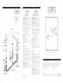
FIG. 01 INSTALACIÓN DE LAS COLUMNAS
Introducir desde abajo en el agujero del sanitario
la columna (1.B) provista de contratuerca (1.C),
banda perfilada (1.D) y junta (1.E). Si el espesor
de la cerámica no permite su fijación, o para dar
más estabilidad al grifo, insertar entre la junta
(1.E) y la cerámica el espesor (1.N). Atornillar
entonces el racor (1.A) a la columna (1.B).
FIG.02 INSTALACIÓN DE LA MANILLA
Atornillar el racor (2.D) a la columna (2.F),
luego atornillar el capuchón (2.C) al racor (2.D)
interponiendo la junta (2.E). Insertar la manilla (2.A)
en posición horizontal y apretar la espiga (2.B).
FIG.01 INSTALACIÓN DE LA BOQUILLA DE
DISTRIBUCIÓN
Introducir por arriba el bloque de la boquilla
de distribución (1.F) en el agujero del sanitario
interponiendo la arandela de base (1.G) y la
junta (1.H). Enroscar sobre el mango roscado
de la boquilla (1.F) la junta (1.I), la brida (1.L),
después apretar la boquilla con la contratuerca
(1.M). Si el espesor de la cerámica no permite su
fijación, o para dar más estabilidad a la boquilla
de distribución, insertar entre la junta (1.F) y la
cerámica el espesor (1.N).
FIG.02 CONEXIÓN DE LOS TUBOS DE
ALIMENTACIÓN
Atornillar la cruceta (2.P) al mango roscado de la
boquilla (2.Q), insertando la junta (2.M). Conectar
el flexible de alimentación (2.N) a la cruceta (2.P)
interponiendo la junta (2.O); conectar el extremo
opuesto del flexible (2.N) a la columna (2.F)
incluyendo la junta.
In the case of operating pressures greater than
5 bar (~75 psi) the use of a pressure reducer is
recommended. Before assembling it is advisable
to clean hot and cold water pipework to prevent
dirt and small impurities from compromising faucet
operation.
FIG.01 STEM INSTALLATION
Insert the stem (1.B) into the gap of the fixture from
below, complete with locking nut (1.C), shaped
flange (1.D) and seal (1.E). If the ceramic thickness
prevents it from being fixed or the faucet from
being stabilised, insert the shim (1.N) between the
seal (1.E) and the ceramic. Then secure the fitting
(1.A) to the stem (1.B).
FIG.02 HANDLE INSTALLATION
Connect the fitting (2.D) to the stem (2.F) and then
secure the cap (2.C) to the fitting (2.D) by placing
the seal (2.E) in between. Insert the handle (2.A)
horizontally and tighten the grub screw (2.B).
FIG.01 SPOUT INSTALLATION
Insert the spout (1.F) into the gap of the fixture
from above inserting the base washer (1.G) and
the seal (1.H) in between. Place the seal (1.I) and
the flange (1.L) onto the threaded stem of the spout
(1.F), then tighten the spout with the locking nut
(1.M). If the ceramic thickness prevents the spout
from being secured properly or making it more
stable, insert the shim (1.N) between the seal (1.I)
and the ceramic.
FIG.02 SUPPLY PIPE CONNECTION
Screw the crosspiece (2.P) to the threaded stem
of the spout (2.Q), by inserting the seal (2.M).
Connect the supply hose (2.N) to the crosspiece
(2.P) by inserting the seal (2.O) in between.
Connect the opposite end of the hose (2.N) to the
stem (2.F), by inserting the seal.
MANTENIMIENTO Y RECOMENDACIONES
TÉCNICAS PRÁCTICAS
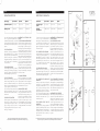
FIG.03 SUSTITUCIÓN DE LA ROSCA
Si fuera necesario sustituir la rosca (3.H), hay que
desmontar la espiga (3.A) y extraer la manilla
(3.B). Destornillar el capuchón (3.C) del racor
(3.D) y destornillar este último de la rosca (3.H).
Destornillar el tornillo (3.F) y extraer el racor
escariado (3.G). Destornillar la rosca (3.H) con
la llave correspondiente, sustituirla si es necesario
y comprobar que las superficies de hermeticidad
de las juntas estén limpias. Volver a montar
efectuando las operaciones inversas, prestando
atención de colocar correctamente la junta (3.E)
debajo del capuchón (3.C). Es conveniente
limpiar periódicamente el atomizador para evitar
la acumulación de residuos y cal que, al pasar
del tiempo, originan una disminución gradual del
caudal. Destornillar el casquete (3.N), extraer el
atomizador (3.M) y limpiarlo de las impuridades.
Al volverlo a montar, interponer siempre la junta
(3.L).
FIG.04 ACCIONAMIENTO DE LAS MANILLAS
Operando sobre las manillas (4.A) y (4.B) se
puede regular el flujo y la temperatura del agua;
girando la manilla (4.B) se regula el caudal de
agua fría, girando la manilla (4.A) se regula el
caliente. Mientras más se alejan de la posición de
cierre, más aumenta el caudal.
MANTENIMIENTO DE LAS SUPERFICIES
Durante la limpieza, la superficie del grifo tiene
que estar fría (el calor acelera el deterioro de la
superficie misma). Comprobar que los productos
de limpieza no contienen ácidos o sustancias
corrosivas. El grifo debe secarse a diario con un
paño suave. Evitar absolutamente los estropajos,
esponjas abrasivas o similares. Justo después de
la limpieza, enjuagar bien los restos de detergente
con agua fría. Los daños a los grifos, consiguientes
a un tratamiento inapropiado, están excluidos de
la garantía.
MAINTENANCE AND TECHNICAL HINTS
AND TIPS
FIG.03 SCREW-DOWN VALVE REPLACEMENT
If it becomes necessary to replace the screw-down
valve (3.H), unscrew the grub screw (3.A) and
remove the handle (3.B). Remove the cap (3.C)
from the fitting (3.D) and loosen the fitting from the
screw-down valve (3.H). Loosen the screw (3.F)
and pull out the broached fitting (3.G). Remove the
screw-down valve (3.H) using the wrench provided;
replace it if necessary and ensure seal surfaces are
clean. Remount in reverse order, making sure the
seal (3.E) is positioned correctly below the cap
(3.C). It is good practice to clean the flow breaker
regularly to prevent the accumulation of dirt and
lime scale, which can cause a gradual decrease
in flow rate over time. Unscrew the cap (3.N),
pull out the flow breaker (3.M) and clear it of any
impurities. When reassembling it, always place
the seal (3.L) in between.
FIG.04 HANDLE OPERATION
Water flow and temperature can be regulated
using the handles (4.A & 4.B): turn handle 4.B to
regulate cold water flow and 4.A to regulate hot
water flow. Flow rate is increased by turning the
handles further from the OFF position.
LOOKING AFTER THE SURFACE
The surface of the faucet should be cold during
cleaning (heat accelerates wear and tear on the
surface itself). Ensure cleaning products do not
contain acids or corrosive substances. The faucet
should be dried daily with a soft cloth. Avoid
using steel wool, abrasive sponges or similar
items. Immediately after cleaning rinse detergent
off with cold water. Damage to faucets resulting
from inappropriate treatment is not covered by the
warranty.
FIG. 01
FIG. 03
FIG. 04FIG. 02
Water Supply Recommended Maximum Minimum
Hot Water Temperature 65 C° (~150F) 80 C° (~175F) 15 C° (~60F)
Working Pressure 3 BAR (~45PSI) 5 BAR (~75PSI) 0.5 BAR (~7PSI)
Alimentación Recomendada Máxima Mínima
Temperatura agua
caliente
65 C° (~150F) 80 C° (~175F) 15 C° (~60F)
Presión de
funcionamiento
3 BARES (~45PSI) 5 BARES (~75PSI) 0.5 BARES (~7PSI)
INSTALLATION INSTRUCTIONS INSTRUCCIONES DE INSTALACIÓN
Based on its policy of steady development Fortis reserves the right to change the characteristics
of the products without notice and therefore the images and data contained in this catalogue may vary.
Por su política de continuo desarrollo, Fortis se reserva el derecho de modificar las características de los productos sin ningún aviso
previo; por tanto, las imágenes y los datos contenidos en el presente catálogo deben considerarse a título indicativo.
  • Page 1 1
  • Page 2 2
  • Page 3 3
  • Page 4 4

Fortis 6010200 Maintenance & Installation Instructions

Categoría
Artículos sanitarios
Tipo
Maintenance & Installation Instructions

El Fortis 6010200 es un dispositivo de grifería con características específicas para la instalación en el baño. Cuenta con temperatura de agua caliente máxima de 80° C, presión de funcionamiento máxima de 5 bar y presión de funcionamiento mínima de 0,5 bar. Su instalación requiere la limpieza previa de las tuberías de agua fría y caliente. En caso de presiones de funcionamiento mayores a 5 bares, se recomienda el uso de un reductor de presión.

En otros idiomas