Norton CTC-705 Series El manual del propietario
- Categoría
- Cortadores universales de potencia
- Tipo
- El manual del propietario

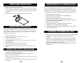
Before operating the unit, please read
this manual thoroughly, and retain it for
future reference.
English Espanol
~
Owner’s Manual
Optional
Saw Stand with Work Bench
CTC-705 Series
2770 West Washington Street, Stephenville, TX 76401
Phone: 800-554-8003
(8:00 A.M. to 7:00 P.M. Eastern Time)
Fax: 800-443-1092

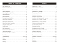
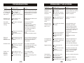
TABLE OF CONTENTS INDICE
Diagrama de la Sierra. . . . . . . . . . . . . . . . . . . . . . . . 3
Lista de Partes de Repuesto. . . . . . . . . . . . . . . . . . . .4,5
Caracteristicas. . . . . . . . . . . . . . . . . . . . . . . . . . . . . 7
Precauciones y Seguridad. . . . . . . . . . . . . . . . . . . . . .8
Desempaque y Ensamble. . . . . . . . . . . . . . . . . . . . . .10
Instalacion de la base
Instalacion de la Cuchilla. . . . . . . . . . . . . . . . . . . . . . 12
Installation del Alojamiento del Cojinete. . . . . . . . . . .. 14
Instalacion de la Bomba de Aqua.. . . . . . . . . . . . . . .15
Mantenimiento la Bomba de Agua. . . . . . . . . . . .
Cuidados con Bomba del Agua. . . . . . . . . . . . . . . . . 16
Profunidad de Corte. . . . . . . . . . . . . . . . . . . . . . . . .20
Remplazamiento de la Banda. . . . . . . . . . . . . . . . . .20
Accesorios Opcionales. . . . . . . . . . . . . . . . . . . . . . .24
Como Usar las Cuchillas. . . . . . . . . . . . . . . . . . . . . .26
. . . . . . . . . . . . . . . . . . . . . . . . 11
16
Uso de la Base de Corte. . . . . . . . . . . . . . . . . . . . . .18
Especificaciones electricas del Motor.. . . . . . . . . . . . 22
Mantenimiento de la Sierra. . . . . . . . . . . . . . . . . . . 28
Problemas y Soluciones. . . . . . . . . . . . . . . . . . . . . .30,32,34
Notas. . . . . . . . . . . . . . . . . . . . . . . . . . . . . . . 36
Garantia. . . . . . . . . . . . . . . . . . . . . . . . . . . . .37
Precaucion. . . . . . . . . . . . . . . . . . . . . . . . . . . . . . .38
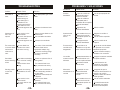
Saw Exploded View. . . . . . . . . . . . . . . . . . . . . . . . . . 3
Replacement Parts List. . . . . . . . . . . . . . . . . . . . . . . .4,5
Features. . . . . . . . . . . . . . . . . . . . . . . . . . . . . . . . .7
Safety Precautions . . . ... . . . . . . .. . . . . . .. . . . . . . . 7
Unpacking, Assembly, & Setup. . . . . . . . . . . . . . . . . . 9
Stand Installation. . . . . . . . . .. . . . . . . . . . . . . . . . . 11
Blade Installation. . . . . . . . . .. . . . . . . . . . . . . . . . . 12
Bearing Housing Installation. . . . . . . . . . . . . . . . . . . 13
Water Pump Installation. . . . . . . . . . . . . . . . . . . . . . . 15
Water Pump Maintenance. . . . . . . . . . . . . . . . . . . . . 15
Water Pump Safety Precautions. . . . . . . . . . . . . . . . . 15
Using the Cutting Table. . . . . . . . . . . . . . . . . . . . . . 17
Cutting Depth. . . . . . . . . . . . . . . . . . . . . . . . . . . . . 19
Belt Replacement. . . . . . . . . . . . . . . . . . . . . . . . . . 19
Electrical Motor Specifications. . . . . . . . . . . . . . . . . 21
Optional Accessories. . . . . . . . . . . . . . . . . . . . . . . . 23
Do’s & Don’t for Diamond Blades. . . . . . . . . . . . . . . . . 25
Saw Maintenance. . . . . . . . . . . . . . . . . . . . . . . . . . 27
Troubleshooting. . . . . . . . . . . . . . . . . . . . . . . . . . . .29,31,33
Notes. . . . . . . . . . . . . . . . . . . . . . . . . . . . . . . 35
Warranty . . . . . . . . . . . . . . . . . . . . . . . . . . . . . .37
Warning. . . . . . . . . . . . . . . . . . . . . . . . . . 38

-4--3-
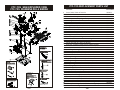
CTC-705 SAW EXPLODED VIEW
CTC-705 DIAGRANA DE LA SIERRA
CTC-705 REPLACEMENT PARTS LIST
PART NAME PART NUMBER
234001
234002
234003
234004
234005
234006
234007
234008
234009-1
233013
234011
234012
234013
233065
234015
234016
233012.1
234018
233049
233012
234023
234024
233017
234026
234027
234028
234041
234030
234043
233053
234018.1
234019
CTC-705
Accessories Included
(Accessorios Incluidos)
CTC-705
Accessories Included
(Accessorios Incluidos)
LCBH
Bearing Housing Package
(Paquete de Cojinete)
LCBH
Bearing Housing Package
(Paquete de Cojinete)
SAW STAND WITH
WORKBENCH
Soporte Dobladizo con
Mesa
SAW STAND WITH
WORKBENCH
Soporte Dobladizo con
Mesa
1
2
3
4
5
6
7
8
9
10
11
12
13
14
15
16
17
18
18.1
19
20
21
22
23
24
25
26
27
28
29
30
31
32
Power Cable/ Cable de Potencia
1 HP Brush Motor
Motor Shaft Pulley/ Polea del eje del motor
Motor Adjustment Clip/ Seguro de Ajuste del Motor
Mounting Plate/ Plato de Ensamble
Belt Guard Bracket/ Brazo de Montaje de la Cubierta de la
Banda
Timing T Shape Nylon Belt/ Banda
Belt Guard/ Cubierta Protectora de la Banda
Belt Guard screws/ Tornillos de la Cubierta Protectora de Banda
Blade Shaft/ Eje Impulsor de Cuchilla
Blade Shaft Pulley/ Polea de Cuchilla
Sliding Rails (set of 2 )/ Rieles Deslizables (2)
Water Pump/ Bomba de Agua
MasterGuide Detachable Ruler Guide/ Regla Detachable
Mounting Plate Adjustment Knob/
Perilla de Ajuste de la Placa de Montaje
Rear Post (Included in Metal Frame & Motor Support
Shaft)/ Poste Trasero (Incluye Estructura Metal y Soporte del
Motor
/ Baleros del Borde Exterior
Inner Flange Bearing
Polypropylene Water Tray/ Bandeja o Deposito del Agua
Drain Plug/ Tapon de Plastico
Motor Protection Cover Shield/ Tornillos de Ensamble
Bearing Housing Lock Bolts and Nuts/ Tuercas y
Seguros del Alojamiento del Cojinete
Bearing Housing Secure Brackets (set of 2)/
Alojamiento del Cojinete Braquetas Aseguradora (2)
Pulley Bearing / Baleros de la Polea
Inner Flange/ Interior el reten de la Cuchilla
Outer Flange/ El reten Exterior de la Cuchilla
Blade Lock Nut/ Tuerca Aseguradora de la Cuchilla
Cutting Table Position Bracket/
Posicion de Braqueta para la Mesa de Cortar
U-Shape Ball Bearing Rollers (set of 2)/
Rueda Acanalada de Cojinete
Miter Block (metal)/ Bloque de Mitra (metal)
Universal Wrench/ Multiple Llave
45º/90° Rip Guide/ 45º/90° Guia de Corta Angular
180° Adjustable Angle Guard/ 180° Guarda Angulo Ajustable
MasterGuide Multiangle Guide/ Guia Maestra
TEMPLATE BASE
Plantilla de Base
TEMPLATE BASE
Plantilla de Base
49

-6--5-
REPLACEMENT PARTS LIST Continue
234035
233033
234036
233019
233045
233018
234040
234041
234042
234043
705STAND
234044
234045
234046
234047
233066
233084
PART NAME PART NUMBER
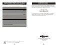
ADDITIONAL HELP
Please call us if for any reason you are having difficulty that
cannot be resolved with the troubleshooting guide included in
the back of this manual. We would like to help.
Give us a call at
1-800-554-8003
To better service our customers as expediently as possible,
please make sure that you have the manufacturing serial
number at hand before contacting us.
33
34
35
36
37
38
39
40
41
42
43
44
45
46
47
48
49
Power Switch Housing(w/ Power Switch,Circuit Breaker, &
Power Cable)/ Alojamiento del Interruptor de Encendido
Power Toggle Switch / Interruptor de Encendido
Circuit Breaker/ Conector del Circuito
Water Flow “T” Adapter/ Adaptador “T” del Flujo de Agua
Water Flow “L” Adapter/ Adaptor de agua “L”
Blade Guard Adjustment Knob/
Perilla de Ajuste del Protector de la Cuchilla
Blade Guard/ Protector de la Cuchilla
Teflon Angle Bar Rollers (set of 2)/ Barras Angular de Teflon
de Rodaje (2)
Cutting Table (Includes Wheels & Ruler Guide)/ Base de
Corta (Incluye Ruedas y Guia de Reglas)
Ruler Guide/ Guia Graduada
Saw Stand with Workbench/ Mesa Dobladiza con Banca de
Trabajo
Complete LCBH(Liquid Cooling Bearing Housing)/
Alojamiento del Cojinete Completo
Rubber Splash Guard/ Protector de Salpicadura de Gamal
Carbon Brushes (set of 2)/ Cepillo del Carbon (2)
Brush Cap/ Tapa del Cepillo
MasterGuide Template Base/ Plantilla de Base
Rear Post Cover/ Cubierta del Poste Posterior
Note: If there is any part that is needed and has not been included in this parts list,
please contact our customer service 1-800-554-8003
2770 West Washington Street, Stephenville, TX 76401
Phone: 800-554-8003
(8:00 A.M. to 7:00 P.M. Eastern Time)
Fax: 800-443-1092

-8-
-7-
SAFETY PRECAUTIONS
1. A Powerful 1 HP brush motor makes cutting easier and quicker.
2. The Automatic Thermal Overload Protection system protects your saw from
power surges and overheating.
3. The high fiber plastic water tray withstands even the toughest punishment yet it
is extremely easy to remove and install.
4. The saw is encased in a sturdy, durable steel frame, optional equipped with
folding stands with work bench for easier operation.
5. Adjustable guide rails permit the user to align the saw during installation.
6. The cutting alignment will not be affected by any water tray maintenance.
7. The cutting table can be secured in place by tightening the knob screw on the
L-shaped transport retention plate.
8. The cutting rip guide is designed for both 90º square cutting and 45º angle
cutting.
9. The 705’s blade capacity is 6"~7"which provides a variety of blade usage.
10. Straight cuts can extend out to 17" in length and diagonal cut up to 12” in
length.
FEATURES PRECAUCIONES Y SEGURIDAD
Our company recommends the use of these Safety Items when
Operating the Saw:
Wear Breathing Protection
Wear Eye Protection
Wear Hearing Protection
Wear Head Protection
Fuel (gasoline) is extremely flammable and its vapors can explode if ignited. Store
gasoline only in approved containers, in well-ventilated, unoccupied approved areas,
and away from sparks or flames. Do not fill the fuel tank while the engine is hot or
running.Do not start the engine near spilled fuel. Never use
the fuel as a cleaning agent.
Engine components can get extremely hot from
operation. To prevent burns, do not touch the
engine or related parts while the engine is running
or immediately after it is turned off. Never operate
the engine with any heat shields or guards
removed.
Keep hands, feet, hair, and clothing away from all
rotating parts.
Keep all guards in place
when operating any piece of
equipment.
Lethal Exhaust Gas use only in well ventilated
areas. Engine exhaust gases contain poisonous
carbon monoxide, which is orderless, colorless, and
can cause death if inhaled. Avoid inhaling exhaust
fumes, and never run the engine in a closed
building or confined area.
Never tamper with the governor components of
settings to increase the maximum speed. Severe
personal injury and damage to the engine or
equipment can result if operated at speed above
maximum. Always obey the maximum speed rating
of blade.
Nuestra compania recomienda el uso de estos Articulos de Seguridad
cuando la Sierra esta en Operacion:
Usar Proteccion De Respirar
Usar Proteccion Para Los Ojos
Usar Proteccion Para Oido
Usar Proteccion De Cabeza
Combustible (gasolina) es sumamente inflamable y sus vapores pueden explotar si
encendidos. Guarde la gasolina sola en contenidos aprovados, vien ventilados, areas
aprovadas inocupadas, y lejos de chispas y llamas. No llene el tanque de combustible
mientras el motor este caliente o funcionando. Nunca use el combustible como un agente
de limpiar.
Componentes del motor pueden ser
sumamente caliente por la operacion. Para
prevenir quemadas, no toque el motor o sus
partes relativas mientras el motor este
funcionando or inmediatamente despues que
es apagado. Nunca use el motor mientras las
cubiertas protectoras o cubiertas de calor esten
removidas.
Mantenga las manos, pies, cabello, y ropa
lejos de las partes girando.
Mantenga todos los protectores
de la cuchilla en su sitio mientras
la sierra esta en operacion.
Gas Mortal de Descarga use solo en areas vien
ventiladas. Descarga del motor contiene
carbon monoxide, que not tiene olor, no tiene
color, y puede causar muerte si es inhalado.
Evite inhalar los humos de descarga, y nunca
use el motor en un edificio cerrado o en una
area cerrada.
Nunca cambia los components governantes de
configuracion para aumentar la velocidad
maxima. Lesion personal severa y dano al
motor o equipo puede resultar si es operado a
una velocidad sobre la maxima velocidad.
Siempre obedece la velocidad maxima de la
cuchilla.
ALWAYS WEAR
SAFETY GEAR
USE
PROPERLY
GROUNDED
CIRCUIT
USE BLADE
GUARD
WHEN
OPERATING
SAW

-10--9-
Open the container, carefully lift the saw by the saw frame handles and
place it on a flat, level working area. Be certain that you have the following
items before you discard the container.
• Saw • Universal Wrench
• Polypropylene Water Tray • Water Pump
• Ø7" Saw Blade • Miter Block
• 45º / 90º Rip Guide • Owner's Manual
Proceed to the following section, to complete assembly of saw.
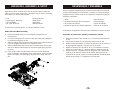
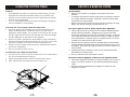
Blade Guard and Blade Assembly
1. Remove the Blade Guard (1) and saw Blade package from the
accessory box.
2. Lift up the cutting head (2) from the insert style-foam that is designed
to re-enforce strength to the box.
3. Slide the cutting head through the rear support post’s shaft as shown in
the lower diagram and screw on the adjustment knob.
4. Slide the Blade Guard into the hex bolt (3) located at the rear of right
side of the Electrical Control Box (5) and fasten tightly using the knob
screw (4).
5. Place the Ø7" blade onto the shaft, make sure that the directional
arrow is pointing in the direction of the shaft rotation. Lift up the Blade
Guard, then fasten the blade tightly using the outer Flange and Lock
Nut.
UNPACKING, ASSEMBLY, & SETUP DESEMPAQUE Y ENSAMBLE
Abra el empaque cuidadosamenta y levante la sierra usando las asas del
armazon depositandola en terreno plano y nivelado en el area de trabajo.
Asegurese de que usted cuenta con los siguientes componentes antes de
desechar el empaque:
• Sierra • Llave Universal
• Deposito para el Agua de Polypropylene • Bomba de Agua
• Ø7" Cuchilla de la Sierra • Tapon de Drenado
• Bloque de Soporte para Cortes Diagonales • Manual de Propietario
Proceda con las siguientes secciones, para ensamblar el resto de la sierra.
Ensamble de protector de cuchilla y ensamble de cuchilla.
1. Remueva el protecor de la cuchilla (1) y la cuchilla (2) empacados en
la caja.
2. Use las asa de metal (3) para remover la maquina de la caja.
3. Deslize la cabeza cortadora en el poste de soporte como se ensena en
la parte baja del diagrama y apriete el tornillo de ajuste.
4. Deslize el protector de la cuchilla en el eje (4) localizado en la parte
trasera de la caja elctica (4) y apriete usando la perilla de ajuste (5)
5. Ponga la sierra de 7 pugadas el eje (6) asegurese que la flecha este
apuando en la direccion correcta de la rotacion del eje.Levante el
protector de la cuchilla, ponga la cuchilla apretandola usando el borde
exterior de la cuchilla (7) y asegurelo con la tuerra (8)

-12--11-
SAW STAND ASSEMBLY
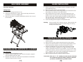
Saw Stand Assembly
Folding Stand
1. Remove the folding stand from its box.
2. Swing the working bench up-right. Open the two legs and place the
work bench on top of the folding stand.
3. After the saw stand is completely assembled, place the saw on top of
the saw stand.
ENSAMBLAJE DEL SOPORTE DE LA SIERRA
Base Dobladiza
1. Remueva la base dobladiza de su caja.
2. Voltee la mesa de trabajo para arriba. Abra las dos patas y ponga la
mesa de trabaja arriba de la base.
3. Despues que la base de la sierra esta completamente ensamblada,
coloque la sierra encima de la base.
1. Raise the blade guard to the highest position and tighten the blade
guard adjustment knob.
2. Remove the blade shaft nut and outer flange.
3. Place the blade onto the shaft making sure that the directional arrows
are pointing in the direction of the shaft rotation.
4. After making sure that the blade is firmly placed against the inner
flange, secure it into place with the outer flange and blade shaft nut.
With one hand hold the blade tightly and tighten the blade shaft nut
with your free hand. Make certain that the nut is firmly tightened with
the wrench provided, but do not over-tighten!
5. Lower the blade guard and tighten the adjustment knob.
Warning: Only use the Ø6"~Ø7” blade for this saw. Setting smaller size
of diamond blade may grab the material being cut, causing
damage and possibly injury.
BLADE INSTALLATION
INSTALACION DE LA CUCHILLA
1. Levante la cubierta protectora a su posicion mas elevada y apriete la
perilla de ajuste.
2. Quite la tuerca del eje impulsor para poder quitar el reten exterior.
3. Coloque la cuchilla cortadora en el eje impulsor asegurandose que la
flechas indicadoras marquen la direccion de rotacion correcta.
4. Despues de asegurarse que la cuchilla este firmemente colocada
contra el reten interior y asegurela en su lugar colocando el reten
exterior y apretando la tuerca en el eje impulsor. Con una mano baje
el seguro de retenida y apriete la tuerca del eje impulsor con su mano
libre, y asegurese que la tuerca este completamente apretada con la
llave incluida en el set, pero no apriete demasiado.
5. Baje la cubierta protectora y apriete la perilla de ajuste.
Precaucion: Solo use Ø6"~Ø7” cuchilla para esta amquina. Poniendo
una cuchilla mas pequena podiria arrebator el material
ya cortado, causando dano y posibles heridas.

-14--13-
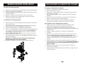
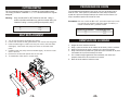
To remove the bearing housing:
1. Remove the 4 screws on the belt guard (Attach to Belt Guard Bracket).
2. Remove the belt guard from Bracket.
3. Loosen the tighten screw from the end of blade's Pulley Shaft, remove
the Belt from Pulley.
4. Remove the blade nut and the blade (if there is one present).
5. Remove the 4 screws on the cutting head to remove the bearing
housing (including the inner flange).
To install the new bearing housing:
1. Be sure that you have completed the instructions above to remove the
old bearing housing.
2. Open the box and carefully place the flat portion of the new bearing
housing face-down on a towel situated on a flat surface.
3. Secure the cutting head in a completely horizontal position.
4. Slide the new Bearing Housing with the flat portion facing upwards onto
the 4 screws located below the Cutting Head. Do this carefully to
avoid damage to the inner flange. Lock the bearing housing into
place by using brackets and nuts.
5. Place the Belt on the pulleys, and make sure the Pulley lock screw is
tight correctly direct to the key pin. Belt tightness has been pre-set, no
adjustment necessary.
Warning: Do not adjust the Inner Flange that is attached the
bearing housing from the original package.
6. Replace the belt guard and lock into place using the 6 screws.
BEARING HOUSING INSTALLATION
Para quitar el alojamiento del cojinete:
1. Retire los 5 tornillos en la cubierta de la banda.
2. Quite la cubierta de la banda.
3. Afloje (pero no quite) ltronillos detras de la polea del eje del motor,
quite la polea y la bonda.
4. Quite la tuerca de seguro y retire la cuchilla de corte (si hay alguna
instalada).
5. Quite la calcomania de precaicion y quite los cautro tornillos para
quitaria la caja electrica de la cabeza cortadora.
6. Retire los cuatro tornillos de la cabeza cortadora para quitar el
alojamineto del cojinete (incluyendo el interior de la cuchilla)
Para instalar el nuevo alojamiento del cojinete:
1. Asegurese de haber completado todas las instruciones arriba
mencionadas para quitar el viejo alojamiento del cojinete.
2. Abra la caja y cuidadosamente coloque la parte plana del nuevo
alojamiento del cojinete con la cara hacia abajo sobre una toalla en una
superficie plana.
3. Asegure la cabeza cortadora en una posicion completamente
horizontal.
4. Deslize el nuevo alojamiento del cojinete con la parte plana vuelta
hacia arriba sobre los cuatro tornillos situados bajo la placa de
montaje. Tenga ciudado de no dañar el reten interior. Asegure el
alojamiento del cojinete dentro de su lugar usando los soportes y
tuercas.
5. Pongla la banda en las poleas y apriete los tornillos de la polea. La
banda se aprieta sola no necesita ajostarse. Precaucion: No ajuste el
reten interior que esta cerca del alojamiento del cojinete de su
paquete original.
6. Reinstale la caja electrica con los cuatro tornillos, re-emplace la
calcomaniade precaucion.
7. Ponga otra vez la cubierta protectora de la banda en su lugar usando
los cuatro tornillos.
INSTALACIONDEL ALOJAMIENTO DEL COJIENTE

-16-
-15-
WATER PUMP SAFETY PRECAUTIONS
• Never operate pump without water in the tray. F
• Be sure to connect the plug to a properly grounded receptacle to
reduce the risk of electric shock.
• Disconnect the pump before attempting to handle the pump, to unclog
or service the pump in any way.
• Be sure to support the pump during installation to prevent pump failure
or damage.
ill the water tray so
that the water intake is fully immersed.
1. Remove the water pump from the box.
2. Place the pump into the middle of the water tray along its side so that
the water outlet is positioned horizontally. Connect the water hose from
the blade guard to the pump and plug the power cord into the 3-prong
receptacle.
3. Fill the water tray so that the water intake is fully immersed.
WATER PUMP MAINTENANCE
When the machine has not been used for a long period of time, hard packed dirt
may begin to build up inside the pump and block the pump wheel. If the machine is
activated with the immersion pump blocked, the electric motor of the pump will be
damaged within a few minutes! Please follow the steps listed below to clean the
pump before operating the saw.
1. Unscrew the pump filter.
2. Remove the immersion pump from the water container.
3. Clean the immersion pump.
4. Loosen the fixing screws of the pump lid.
5. Take the lid off the pump (be careful not to damage the gasket located inside
with a sharp object!)
6. Clean the pump lid.
7. Remove all dirt and incrustations from the pump wheel.
8. Check whether the pump wheel can be easily turned.
9. Then reassemble the immersion pump correctly and check whether it works
properly.
WATER PUMP INSTALLATION
MANTENIMIENTO DE LA BOMBA DE AGUA
CUIDADOS CON BOMBA DEL AGUA
Cuando la maquina no ha sido usada por periodo largo de tiempo, quizas la
bomba y el rodete podrian estar atascados con residuos secos. Si la
maquina es encendida con la bomba de immersion atascada, el motor
electrico de la bomba podria danarse en pocos minutos! Por favor siga la
indicaciones paso a paso para limpiar la bomba antes de usar la sierra.
Desatornille el filtro de la bomba.
Quite la bomba de hundimiento de la bandeja del agua.
Limpie la bomba de hundimiento.
Afloje los tornillos de fijacion de la tapadera de la bomba.
Retire la tapadera de la bomba (tenga cuidado) no dane el empaque
de adentro con herramienta afilada.
Limpie la tapa de la bomba.
Quite toda la suciedad y residuos del rodete de la bomba.
Compruebe que el rodete puede girar libremente.
Ensamble la bomba de hundimiento correctamente y comprube que
todo trabaje propiamente.
1.
2.
3.
4.
5.
6.
7.
8.
9.
•
•
•
•
Nunca use la bomba sin agua en la bandeja. Llene la bandeja de agua
de manera que el agujero de absorsion quede completamente
hundido.
Asegurese de conectar el enchufe a un toma corriente conectado a
tierra en forma apropriada para reducir el riesgo de choque electrico.
Desconecte la bomba antes de manejarla o tratar de desmontarla o
dar servicio a la bomba en cualquier forma.
Asegurese de sostener la bomba durante la instalacion para prevenir
danos o fallas.

-18--17-
USING THE CUTTING TABLE
Features:
• The Adjustable ruler guide (1) enable easy oversize cutting, it is also
equipped with inches and centimeters marks (2) for precision cuts.
• Simply line up the material being cut with the appropriate pre-marked
lines (3) on the cutting table.
• The 14” cutting table provides more support during larger cutting jobs
than the standard 11" cutting tables.
To use the 45º / 90º rip guide, follow the steps below:
1. Set the rip guide (4) by positioning it on the desired dimension and
tighten the threaded knob. Make sure that the rip guide is firmly
tightened to avoid slippage. The rip guide can be used for 90º rip cuts
and 45º angle cuts from both the left and right side. (Note the straight
and 45º angled slits on the bottom of the rip guide.)
2. After the rip guide is positioned for the desired cut, place material flat
against the rip guide and the measurement rail. For 45º rip cuts, place
the corner of material in the open slot of the measurement rail.
3. Simply line up the material being cut with the appropriate pre-marked
lines on the cutting table.
4. Now you are ready to make your cut.
To make miter cuts, follow the steps below:
1. For miter cuts (5), place the lip of the miter block on the measurement
rail, with the threaded knobs facing you.
2. Tighten the threaded knobs to secure the miter block in place.
3. Place material onto miter block and you are ready to cut.
USO DE LA BASE DE CORTE
Caracteristicas
ase de corte marcado en pulgadas y centimetros para cortes
precisos.
La cubierta de goma de la base de corte ayuda a mantener el material
en su lugar mientras es cortado, resistiendo. Vibraciones para cortes
mas suaves con menos astillas.
Base de corte de 16" provee mas apoyo durante los trabajos de cortes
largos, mas que las bases de corte estandard en 11".
Para usar la guia de corte de 45/90º siga los pasos siguientes
Instale la guia de corte (4) colocando en la medida deseada despues
apriete la perilla atornillable. Asegurese que la guia de corte esta
firmemente apretada para evitar que el material se resbale. La guia de
corte puede ser usada para cortes de 90 y cortes en angulo de 45 por
los 2 lados derecho e izquierdo (Nota: los angulos rectos y de 45 son
cortados en la parte baja de la guia de corte.
Despues de que la guia de corte este instalada para el corte deseado,
ponga el material completamente plano contra la guia de corte y el riel
de medida. Para cortes 45 ponga la esquina en la ranura abierta en el
riel de medida.
Simplemente alinie el material a cortar con las lineas premarcadas
apropiadas en la base de corte.
Ahora ya usted esta listo para realizar su corte.
Para hacer cortes en diagonal, continue con los siguientes pasos
Para cortes diagonales (5)coloque el borde del soporte, para cortes en
angulo en el riel de medicion con las perillas atornillables de frente a
usted.
Apriete las perillas atornillables para asegurar el soporte de corte
diagonal en su lugar.
:
•B
•
:
1.
2.
3.
4.
:
1.
2.
•
3
2
1
1
4

-20--19-
CUTTING DEPTH
The recommended cutting depth is ¼" below the cutting table surface.
The cutting clearance in between 1-½”~1-¾” has been fixed from original
designed.
Warning: Only use either Ø6" or Ø7" blades for this saw. Using a
smaller size diamond blade may grab the material being cut
instead of cutting it, causing damage and possibly injury.
Blade Diameter
6”
7”
Cutting Depth
1-½”
1-¾”
BELT REPLACEMENT
1. Turn off the saw before proceeding any further.
2. Loosen and remove the belt guard screws, then remove the belt guard.
3. Leave the blade tight in position and use your hand to hold the blade
shaft tightly. Now loosen the pulley lock screw on the blade shaft
pulley.
4. Carefully loosen the pulley and belt outward slightly, so there is a little
slack in the belt.
5. Remove the old belt and replace with the new belt.
6. To reassemble, follow steps in reverse order.
PROFUNIDAD DE CORTE
La profundidad recomendad de corte es de 1/4" bajo la superficie de la
base de corte. Para ajustar la profunidad de corte, afloje la perilla de
ajuste de la placa de montaje hasta que la cuchilla se encuentre a 1/4"
bajo la superficie superior de la base de corte.
Precaucion:Solo use cuchilla de Ø6" or Ø7" para esta maquina poni endo
una cuchilla mas pequena podria arre batar el material y a
cortado causando dano y posibles heridas
1.
2.
3.
4.
5.
Apague la sierra antes de continuar.
Afloje y quite los tornillos de la cubierta de la banda y retire la cubierta.
Afloje las 4 tuercas (de atras y enfrente) en la placa de montaje.
Afloje suavemente el pasador de ajuste del motor localizado en la parte
mas trasera de la placa de montaje de motor.
Con cuidado empuje ligeramente hacia adelante, ahi notara una
pequena disminucion de la tension en la banda.
Retire la banda usada e instale la nueva.6.
Diametro De La Cuchilla
6”
7"
Profunidad De Corte
1-½”
1-¾”
REMPLAZO DE LA BANDA

-22--21-
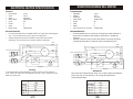
ELECTRICAL MOTOR SPECIFICATION
Warning
To avoid permanent motor damage you must use the correct extension
cord. Never use more than one extension cord at a time. Follow the chart
below for proper size:
1 HP
115V
25'
50'
75'
-
WIRE
GAUGE
No. 12
No. 10
No. 8
No. 6
LENGTH OF CORD
Features:
• Horsepower 1 H.P.
• Volts 115 V
• Amps 15 Amps
• Motor RPM 18000 RPM
• Cycle 60
• Phase 1
• Class E
• Blade Shaft 10000 RPM
Recommendations:
• It is recommended that a 15 AMP CIRCUIT be used while operating this
saw. This will prevent any loss of power or interruption.
• Always plug saw as close as possible to the power source while
operating. This will allow you to receive optimum electricity.
Power Outlet for Water Pump
Power cable
Capacitor
Overcurrent
Breaker
Wiring Box
Motor
Green
Green
Green
Black Black
Black
Black
White White
White
White
White
Switch
ESPECIFICACIONES DEL MOTOR
Advertencia
Para evitar dano permanente al motor use el cable correcto de extension.
Nunca use mas de una extension a la vez siga las indicaciones
proporcionadas abajo:
LARGO DEL CABLE
1 HP
115V
25'
50'
75'
-
GROSOR
DE CABLE
No. 12
No. 10
No. 8
No. 6
Caracteristicas
Caballaje
Voltios
Amperios
Ciclos
Fase
Clase
Recomendaciones
Es recomendado que un circuito de 15 amps sea usada mientras la
sierra esta en operacion esto evitara la interrupcion o perdido de
potencia.
Siempre conecte la sierra lo mas cerca posible a la fuente de poder
mientras la sierra este en operaicon esto le permetira recivir la
:
• 1 H.P.
• 115 V
• 15 Amps
• Motor RPM 18000 RPM
•60
•1
•E
• Eje Impulsor de la Cuchilla 10000 RPM
:
•
•
Power Outlet for Water Pump
Power cable
Capacitor
Overcurrent
Breaker
Wiring Box
Motor
Green
Green
Green
Black Black
Black
Black
White White
White
White
White
Switch

-24--23-
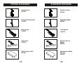
OPTIONAL ACCESSORIES ACCESORIOS OPCIONALES
Template Base
233066
Detachable Ruler Guide
233065
MasterGuide
233053
Plantilla de Base
233066
Regla Detachable
233065
Guia Maestra
233053
Angle Guide
234043
Guia de Corte en
Angulo
234043
Side Extension Table
233036
Extension de la Base
de Corte
233036

-26--25-
DO'S & DON'TS FOR BLADES QUE HACER Y NO HACER CON LAS CUCHILL AS
WET CUT BLADES
DO'S
Inspect blades daily for cracks or uneven wear.
Always use appropriate blade for material being cut.
Inspect arbor shaft for uneven wear before mounting blade.
Always use blades with the correct arbor shaft size.
Ensure that blade is mounted in the correct direction.
Secure the blade to the arbor with a wrench.
Use proper safety equipment when operating the saw.
Periodically check the blade for cracks or bond fatigue.
Always have a continuous flow of water on both sides of blade.
DON'TS
Do not operate the saw without safety guards in position.
Do not operate the saw with blades larger than 7”.
Do not cut dry with blades marked "Use Wet".
Do not exceed manufacturer's recommended maximum RPM.
Do not force blade into material let blade cut at its own speed.
DRY CUT BLADES
DO'S
In addition to the following, always follow wet recommendations.
Use appropriate blade for material being cut.
Inspect segment blades for segment cracking or loss.
Do not use damaged blades.
Use proper safety equipment when operating the saw.
DON'TS
In addition to the following, always follow wet recommendations.
Do not make long cuts with dry blades--allow them to air cool periodically.
Do not use the edge or side of blade to cut or grind.
Do not attempt to cut a radius or curve.
Do not cut too deep or too fast into the material.
CUCHILLAS DE CORTE HUMEDO
QUE HACER
Revise las cuchillas diariamente por grietas o desgaste disparejo.
Siempre use la cuchilla apropiada para el material que se va a cortar.
Revise el eje por desgaste disparejo antes de instalar la cuchilla.
Use siempre cuchilla con la medida necesaria para el eje.
Asegure se que la cuchilla este montada en la direccion correcta.
Asegure la cuchilla al eje con una llave.
Use el equipo de seguridad apropiado cuando se encuentre operando la sierra.
Periodicamente revise la cuchilla por grietas o abolladuras.
Siempre tenga un constante flujo de agua en ambos lados de la cuchilla.
QUE NO HACER
No haga uso de la sierra sin las cubiertas de seguridad.
No use la sierra con cuchillas mas largas de 7".
No haga cortes en seco cuando la cuchilla esta disenada para uso humedo.
No exeda el maximo de RPM recomendadas por el fabricante.
No force la cuchilla cuando este realizando el corte deje que la cuchilla
avance por si misma.
CUCHILLAS DE CORTE EN SECO
QUE HACER
Ademas de lo siguiente siemple siga las recomendaciones de corte humedo.
Use la cuchilla apropiada para el material a cortar.
Revise la cuchilla con mucho cuidado buscando grietas o quebraduras.
No use cuchillas danadas.
Use el equipo de seguridad adecuado cuando use la sierra.
QUE NO HACER
Ademas de lo siguiente siempre siga las recomendaciones de corte
humedo.
No haga cortes largos con cuchillas para corte seco. Permita el
enfriamiento con aire periodicamente.
No use el filo o los costados de la cuchilla para cortar o esmerilar.
No trate de cortar en circulo o curvas.
No haga cortes muy profundos o rapidos en el material.
No corte cualquier material que no sea recomendado por el fabricante de la
cuchilla.

Maintenance Interval
After every use of the
machine
After wet cleaning and
before using the machine
again
Before not using the
machine for a prolonged
period of time
After not using the
machine for a prolonged
period of time
Ambient temperature
below 32 F (operation in
winter)
What to do for maintenance and care
Remove dirty water from container.
Remove dirt and mud from the bottom of the
container.
Rinse the immersion pump with fresh water to
prevent water pump clogging from residual dirt.
Connect the machine to an electric power
outlet equipped with a "GFI" safety power
breaker. If the safety power breaker cuts off
the electrical power supply, do not try to
operate the machine but have it checked by an
authorized dealer first.
Clean and lubricate all movable parts.
Check that the stand is safely fixed.
Check that all screw joints and nuts are fixed.
Check that the roller table is in its guides and
that it easily moves to and fro.
With the saw blade removed, switch on the
motor for an instant and switch it off again. If
the motor does not run, have the machine
inspected by a qualified electrician.
Check that the immersion pump works
properly. Turn on the cooling water tap and
switch the machine on. If the pump does not
give any water or only a little, switch the
machine off at once. Clean the pump, or
replace if necessary.
To prevent the water in the pump and cooling
system from freezing, remove the water after
using the machine or when there will be a long
break. Make sure that the cooling system is
entirely drained so that there is no water left
inside the pump, water hose and bearing
housing!
-28--27-
SAW MAINTENANCE MANTENIMIENTO DE LA SIERRA
MANTENIMIENTO DE LA SIERRA
Periodo de mantenimiento
Despues de cada uso de la
sierra
Despues de limpiar y antes
de usar la maquina
nuevamente
Antes de no usar la
maquina por un periodo
prolongadro de tiempo
Despues de un prolongado
periodo de tiempo sin uso
Temperatura ambiente
trabajando a 32 F (El uso
Como cuidar y mantener la sierra
Vacie el agua sucia del deposito.
Quite la suciedad y los residuos del deposito.
Enjuage la bomba de hundimiento con agua
limpia para prevenir que se atasque con
residuos y basura.
Conecte la maquina a un toma corrientes
equipado con un interruptor de seguridad. Si
el interruptor corta la corriente. No trate de
usar la maquina primero tendra que ser
revisada por un distribuidor autorizado.
Limpie y lubrique todas las partes moviles.
Revise que el soporte estan seguramente
fijos.
Revise que todos los tornillos y tuercas esten
arreglados.
Revise que la base de rodetes esta en sus
guias y se puede mover libremente.
Con la cuchilla de la sierra desmontada,
encienda el motor por un instante y vuelvala a
apagar. Si el motor no trabaja, la maquina
debera ser revisada por un electricista calificado.
Revise que la bomba de hundimiento trabaje de
manera correcta encienda el proveeder de agua
y encienda la maquina. Si la bomba no provee la
sificiente agua o nada. Apague la maquina.
Limpie la bomba a reemplacela si es necesario.
Para prevenir que el agua en la bomba o en
el sistema de enfriamiento no se congele. No
deje agua en el deposito despues de cada uso
o cuando se dejara sin uso por un tiempo
prolongado. Asegureze que el deposito y el
sistema de enfriamiento esta completamente
vacio y que no hay agua, la bomba ni en las

Problem
Machine does
not run when
switched on
Motor stops
(power cut out)
Poor machine
performance
little power
Solution
heck that the machine is
properly connected to the
power supply
ave the power cord
checked, replace if necessary
ave the main power switch
checked and replace if
necessary by a qualified
electrician
C
H
H
Have the whole electric
system of the machine
checked by a qualified
electrician
Have the motor checked
and replaced if necessary by
a qualified technician
Exert less pressure when
cutting
Use a saw blade which
corresponds to the material
being cut
Have the electric system of
the saw checked by a
qualified technician
Use a power cord/extension
cable of the rated length, use
a cable drum with cable fully
extended
Observe the electrical
ratings of the machine and
connect it only to a power
network which complies with
these ratings
Have the motor checked by
a qualified electrician and
have it replaced if necessary
Possible Cause
Power cord not properly
fixed/plugged in
Power cord defective
Main power switch
defective
Loose electrical
connection inside the
electric system
Motor defective
Too much pressure
exerted while cutting
Incorrect specification
for saw blade
Saw has a defective
electric system
Power cord/extension
cable too long or cable
still wound up inside
cable drum
Power network is
insufficient
Drive motor no longer
runs at rated speed RPM
-30--29-
TROUBLESHOOTING PROBLEMAS Y SOLUCIONES
Problemas
La maquina no
trabaja cuando
es activada
Desativacion
continua del
motor
Pobre
rendimiento o
poco poder
Solucion
Revise la maquina si esta
correctamente conectado a
tomacorriente
Revise el cable conetor y
re-emplacelo si es necesario
Revise el interruptor
principal y si es necesario
debera ser cambiado por un
electricista calificado
El sistema electrico debera
ser revisado completamente
por un electricista calificado
Revise el motor y re-
emplacelo si es necesario
Ejerza menos presion
cuando realize el corte
Utilize la cuchilla de sierra
que corresponde al material
a cortar
El sistema electrico de la
sierra debera ser revisado
por un tecnico calificado
Use cable conector o
extension de la medida
indicada use la bovina con el
cable completamente
extendido
Observe los requerimientos
electricos de la maquina y
conectela a la linea de
corriente que cumpla con los
requerimientos
Haga que el motor sea
revisado por un electricista
calificado y remplazelo de ser
necesario
Posible causa
Cable conector no esta
fijo o conectado en la
forma correcta
Cable conector
defectuoso
Interruptor principal de
fectuoso
Perdida de coneccion
electrica dentro el
sistema electrico
Motor defectuso
Demasiada pression es
aplicada mientras esta
realizando el corte
Especificacion
incorrecta de la cuchilla
de la sierra
La sierra tiene sistema
electrico defectuoso
Cable conector o
extension demasiado
largo o el cable ha sido
danado dentro de la
bovina
Linea de corriente es
insuficiente
El motor no trabaja a la
velocidad de corte
requerida

Problemas
Insuficiente flujo
de liquido
enfriafor o nada
de liquido
Funcionamiento
irregular de la
cuchilla de la
sierra
Balanceo de la
cuchilla cuando
esta en uso
Los segmentos
de diamante se
aflojan
Degaste excesivo
Cuarteaduras
en, o cerca de
los segmentos
de diamante
Solucion
Llene el deposito con agua
Limpie el filtro de la bomba
Desarme la bomba de
imersion y limpiela
Regrese la cuchilla al
fabricante
La cuchilla debera ser
enderezada y alineada
Limpie el borde receptor
Solde los segmentos de
diamante de la cuchilla vieja
en otra buena o use una
cuchilla nueva
Reemplace el borde de la
cuchilla
Reemplace el motor
electrico
Solde los segmentos de
diamante en la cuchilla
nuevamente y asegure
liquido enfriador suficiente
Use una cuchilla mas fuerte
Remplace los valeros del
motor o el motor completo
Asegure flujo de liquido
enfriador suficiente
Use una cuchilla mas suave
Remplace los bordes de
ajuste
–Remplace los baleros del
eje del motor
Posible Causa
La bomba arrastra aire
Filtro tapado
La rueda de la bomba
de imersion esta tapada
con residuos
Pobre resistencia en el
material de la cuchilla
La cuchilla esta danada
o doblada
Borde de la cuchilla de
la navaja esta danado
Eje del motor esta
doblado
Sobrecalentamiento de
la cuchilla e insuficiente
liquido enfriador
Tipo equivocado de
cuchilla
El eje del motor causa
balanceo
Sobrecalentamiento
Cuchilla de la sierra
demasiado dura
Los bordes de ajuste
estan desgastados
Baleros del eje del motor
-32--31-
TROUBLESHOOTING PROBLEMAS Y SOLUCIONES
Problem
Insufficient flow
of cooling water
or no cooling
water at all
Irregular run of
the saw blade
Saw blade
wobbles when
running
Diamond
segment
becomes loose
Excessive wear
Cracks in or
near the
diamond
segment.
Solution
Fill the container with water
Clean the filter of the pump
Disassemble the immersion
pump and clean it
Return the saw blade to the
manufacturer
Have the saw blade
aligned/flattened
Clean the receiving flange
Solder the diamond
segments of the old blade
onto another saw blade or
use a new blade
Replace the saw blade
flange
Replace the electric motor
Have the diamond segment
soldered on the blade again;
ensure optimum flow of
cooling water
Use harder saw blades
Have bearings of the motor
or the motor replaced
Ensure optimum flow of
cooling water
Use a softer blade
Have the fixed flange
replace
Replace the bearing of the
motor shaft
Possible Cause
The pump draws air
Filter clogged
Pump wheel of the
immersion pump blocked
by dirt
Poor tension in the
blade material
Saw blade is damaged
or bent
Flange of the saw blade
is damaged
Shaft of the motor is
bent
Overheating of the saw
blade; cooling water not
sufficient
Wrongtype of saw blade
Shaft of motor causes
wobbling
Overheating
Saw blade too hard
Fixed flange is worn out
Motor shaft bearing

Posible Causa
El tipo de cuchilla es
inhapropiado para el
material a cortarse
El tipo de cuchilla es
inhapropiado para el
rendimiento de la maquina
Cuchilla demasiado
dura
Segmentos de
diamante desafilados
Poca resistencia en el
material de la cuchilla
Demasiada presion en
la cuchilla
Los segmentos de
diamante desafilados
La cuchilla se ha
resbalado en el eje del
motor mientras funciona
Sobrecalentemiento de
la cuchilla debido a la
falta de liquido enfriador
Rozamiento lateral
cuando corta
El material no esta
siendo alimentado
paralelamente a la
cuchilla
Poca resistencia en el
material de la cuchilla
Demasiada presion en
la cuchilla
Possible Cause
Saw blade type is
unsuitable for the
material being cut
Saw blade type is
unsuitable for the
machine performance
Saw blade too hard
Diamond segments are
blunt
Poor tension in the
blade material
Too much load placed
on the saw blade
Diamond segments are
blunt
The saw blade has
slipped on the motor
shaft when running
Saw blade overheating
due to a lack of cooling
water
Lateral friction when
cutting
Material is not being
fed parallel to the saw
blade
Poor tension in the
blade material
Too much load on the
saw blade
Problem
Saw blade is
blunt
Appearance of
cut is not
optimal
The center hole
in the saw blade
has become
wider due to
wear
Saw blade
shows blooming
colors
Grinding marks
on the saw
blade
-34--33-
TROUBLESHOOTING PROBLEMAS Y SOLUCIONES
Solution
Use appropriate type of saw
blade
Sharpen the diamond saw
blade
Return the saw blade to the
manufacturer
Use a suitable saw blade
Sharpen the saw blade
The arbor of the saw blade
must be fitted with an
appropriate adaptor ring
Check the receiving flange
and have it replaced if
necessary
Ensure an optimum flow of
cooling water
The material feed is too
high; proceed more slowly
Ensure that the direction of
feed is absolutely parallel to
the saw blade
Adjust the roller table/have
it adjusted
Have the saw blade
tensioned
The material feed is too
high, proceed more slowly
Problemas
Cuchilla
desafilada
Apariencia del
corte no es
buena
El centro de la
cuchilla se ha
desgastado
La cuchilla
muestra colores
brillantes
Marcas de
esmerilado en la
cuchilla
Solucion
Use el tipo apropiado de
cuchilla
Afile la cuchilla
Regrese la cuchilla al
fabricante
Use la cuchilla requerida
Afile la cuchilla de la
maquina
El eje de la cuchilla debera
ser ajustado con un anillo
adaptador apropiado
Revise el borde receptor y
cambielo si es necesario
Asegure la maxima cantidad
de liquido enfriador
La alimentacion del
material es muy rapida
continue mas despacio
Asegurese de que la
direccion de alimentacion es
paralela a la cuchilla
Ajuste la base de rodillos o
mande ajustarla
Use la cuchilla adecuada
El material esta siendo
alimentado muy rapido
continue mas despacio

-36--35-
NOTES NOTAS

-37-
WARNING
DUST AND SILICA WARNING
Grinding/cutting/drilling of masonry, concrete, metal and other materials can generate
dust, mists and fumes containing chemicals known to cause serious or fatal injury or
illness, such as respiratory disease, cancer, birth defects or other reproductive harm. If
you are unfamiliar with the risks associated with the particular process and/or material
being cut or the composition of the tool being used, review the material safety data sheet
and/or consult your employer, the material manufacturer/supplier, governmental agencies
such as OSHA and NIOSH and other sources on hazardous materials and make certain to
comply with all product warnings and instructions for the safe and effective use of the
material being cut. California and some other authorities, for instance, have published
lists of substances known to cause cancer, reproductive toxicity, or other harmful effects.
Control dust, mist and fumes at the source where possible. In this regard use good work
practices and follow the recommendations of the manufacturer/supplier, OSHA/NIOSH, and
occupational and trade associations. Water should be used for dust suppression when wet
cutting is feasible. When the hazards from inhalation of dust, mists and fumes cannot be
eliminated through engineering controls such as either vacuum and/or water mist, the operator
and any bystanders should always wear a respirator approved by NIOSH/MSHA for the material
being cut.
1. Always clean the machine before maintenance/repair.
2. Before cleaning/maintenance/repair, the machine must be switched off with the main
power key.
3. Clean the machine by following the steps below:
a. Please do not use aggressive cleaners (i.e. containing solvents). Do not use high-
pressure water jets, aggressive detergents or solutions and liquids with a
temperature exceeding 86 F! Use a fluff-free cloth only.
b. Use a cloth which may be lightly moistened only for removing dust and dirt. Hard
packed dirt can be removed with a soft brush.
c. For the sake of safety, no water/cleaning liquid/vapor may penetrate into the electric
motor, connectors/plugs, switches, etc. Therefore cover all apertures, holes in the
housing, connectors or plugs, etc. or seal them with adhesive tape!
d. Use a soft, low-pressure water jet and a brush to rinse dirt and incrustations away.
Be particularly careful when near hazardous parts of the machine (e.g. switch,
motor). Clean the motor and switches only by wiping with a moist cloth.
e. Do not "rinse" the bearings of the drive elements to prevent them from running dry.
The ball bearings of the machine are permanently lubricated.
f. After cleaning, remove all covers and adhesive tape! All screws/nuts which you may
have loosened must be tightened again!
g. After wet cleaning, try the machine on a power outlet which is equipped with a
power breaker (i.e. fault current circuit breaker). If the fault current circuit breaker
cuts the power supply, the machine must be inspected by an authorized dealer prior
to use!
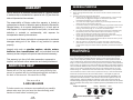
GENERAL PURPOSE
-38-
Norton warrants all products manufactured by it against defects
in workmanship or materials for a period of one (1) year from the
date of shipment to the customer.
The responsibility of Norton under this warranty is limited to
replacement or repair of defective parts at Norton's Gainesville,
Georgia factory, or at a point designated by it, of such part as
shall appear to us upon inspection at such point, to have been
defective in material or workmanship, with expense for
transportation borne by the customer.
In no event shall Norton be liable for consequential or incidental
damages arising out of the failure of any product to operate
properly.
Integral units such as gasoline engines,electric motors,
batteries,tires,transmissions,etc., are excluded from this
warranty and are subject to the prime manufacturer's warranty.
This warranty is in lieu of all other warranties, expressed or
implied, and all such other warranties are hereby disclaimed.
ADDITIONAL HELP
Please call us if for any reason you are having difficulty that
cannot be resolved with the troubleshooting guide included in
the back of this manual. We would like to help.
Give us a call at
1-800-554-8003
To better service our customers as expediently as possible,
please make sure that you have the manufacturing serial
number at hand before contacting us.
WARRANTY
Eye Protection
Always use approved: Hearing
Protection
Respiratory
Protection
Head
Protection
You Are Responsible For Your Safety!!!
-
 1
1
-
 2
2
-
 3
3
-
 4
4
-
 5
5
-
 6
6
-
 7
7
-
 8
8
-
 9
9
-
 10
10
-
 11
11
-
 12
12
-
 13
13
-
 14
14
-
 15
15
-
 16
16
-
 17
17
-
 18
18
-
 19
19
-
 20
20


Norton CTC-705 Series El manual del propietario
- Categoría
- Cortadores universales de potencia
- Tipo
- El manual del propietario
Otros documentos
-
Husqvarna FS 305 Manual de usuario
-
MasterForce 709-3932 El manual del propietario
-
 Craftsman ProSeries TJZ10/3 El manual del propietario
-
Craftsman 124.3299 El manual del propietario
-
-
-
Rikon Power Tools 10-321 El manual del propietario
-
Craftsman Professional 351.224010 Manual de usuario
-
-
Makita LB1200F El manual del propietario
