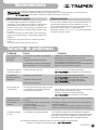
Truper COMBO-120/160 El manual del propietario
- Categoría
- Herramientas eléctricas
- Tipo
- El manual del propietario

Manual
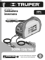
Inverter Welder
SOIN-120/160
Model Code
SOIN-120/160
Applies for:
13695
CAUTION
ENGLISH
ESPAÑOL
40%
Work Cycle
Read this manual thoroughly
before using the tool.

2
Technical specifications
Power Requirements
General Power Tools Safety Warnings
Safety Warnings for Inverter Welders
Parts
Installation (SMAW)
Installation (TIG)
Start Up
Maintenance
Troubleshooting
Symbology
Authorized Service Centers
Warranty Policy
3
3
4
5
6
7
8
9
SOIN-120/160
ENGLISH
11
11
12
13
14
Contents
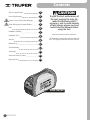
CAUTION
Keep this manual for future references.
The illustrations in this manual are for reference
only. They might be different from the real tool.
To gain the best performance of
the tool, prolong the duty life,
make the Warranty valid if
necessary, and to avoid hazards
of fatal injuries please read and
understand this Manual before
using the tool.

3
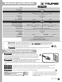
Technical specifications
ENGLISH
13695
Code
Description
SOIN-120/160
Power
Power cord grips: Type “Y”.
Build quality: Basic insulation.
Thermal insulation on motor winding: Class H
No. of Phases 2 phase1 phase
Current 39.5 A
Frequency 50 Hz / 60 Hz
Inverter Welder
Input
Output
127 V 220 V
Fan Forced
Open Circuit Voltage
15 A - 160 A15 A - 130 A
Current Range
Cooling Type
SMAW: 78 V c.c. TIG: 14,6 V c.c.SMAW: 90 V c.c. TIG: 14,6 V c.c.
IP21S
IP Grade
12.3 lb
Weight
40% 4 minutes’ work per 6 minutes’ rest.
Work Cycle
Insulation Class I
12 AWG x 2C with 221 °F insulation temperature
Conductors
7,7 kVA5 kVA
Input Rated Capacity
3
Power Requirements
If faults or breakdowns happen. Ground connection offers a
trajectory with minimum resistance for electric power. It reduces the risk of electric
shock. This tool is built with a power cable with an earth conductor and a plug with
ground connection. The plug shall be connected into a power outlet installed and
grounded according to all local codes.
Do not modify the plug supplied. If the plug cannot be fitted
to the socket, have a qualified electrician to install the suitable socket.
• When using the welder together with more tools using the same ground connect those in parallel, never connect a
series.
• The gauge of the ground conductor cable shall not be of a smaller gauge than the power supply cable.
• Connection to the power supply shall only be carried out by a professional electrician.
• Double check the input connection voltage stipulated in the welder nameplate matches the power
supply voltage.
• The power supply cord shall meet the following requisites:
CAUTION
CAUTION
CAUTION
* The current for fuse fusion is double of its rated current.
Switch
Fuse (Work Rated Current)
Electric Wire
30 A
30 A (*)
2,5 mm2
• If extensions between the welder and the work piece
are needed, the soldering cable gauge shall be increased
to keep the welder energy output with a potential drop
not higher than 4 V
CAUTION
Output values specified are with a 68 ºF Temperatures higher than the work cycle may be reduced.
WARNING
WARNING Avoid the risk of electric shock or severe injury. When the power cable gets damaged
it should only be replaced by the manufacturer or at a Authorized Service Center.
The build quality of the electric insulation is altered if spills or liquid gets into the tool while in use.
Do not expose to rain, liquids and/or dampness.
Before gaining access to the terminals all power sources should be disconnected.
WARNING
WARNING
Bi-Voltage automatic adaptation system

4
General Power Tools
Safety Warnings
ENGLISH
Work area
Keep your work area clean, and well lit.
Cluttered and dark areas may cause accidents.
Never use the tool in explosive atmospheres, such as in the
presence of flammable liquids, gases or dust.
Sparks generated by power tools may ignite the flammable material.
Keep children and bystanders at a safe distance while operating
the tool.
Distractions may cause loosing control.
Electrical Safety
The tool plug must match the power outlet. Never modify
the plug in any way. Do not use any adapter plugs with
grounded power tools.
Modified plugs and different power outlets increase the risk of electric shock.
Avoid body contact with grounded surfaces, such as pipes,
radiators, electric ranges and refrigerators.
The risk of electric shock increases if your body is grounded.
Do not expose the tool to rain or wet conditions.
Water entering into the tool increases the risk of electric shock.
Do not force the cord. Never use the cord to carry, lift or unplug
the tool. Keep the cord away from heat, oil, sharp edges or
moving parts.
Damaged or entangled cords increase the risk of electric shock.
When operating a tool outdoors, use an extension cord suitable
for outdoor use.
Using an adequate outdoor extension cord reduces the risk of electric shock.
If operating the tool in a damp location cannot be avoided, use
a ground fault circuit interrupter (GFCI) protected supply.
Using a GFCI reduces the risk of electric shock.
Personal safety
Stay alert, watch what you are doing and use common sense
when operating a tool. Do not use a power tool while you are
tired or under the influence of drugs, alcohol or medication.
A moment of distraction while operating the tool may result in personal injury.
Use personal protective equipment. Always wear eye
protection.
Protective equipment such as safety glasses, anti-dust mask, non-skid shoes,
hard hats and hearing protection used in the right conditions significantly
reduce personal injury.
Prevent unintentional starting up. Ensure the switch is in the
“OFF” position before connecting into the power source and /
or battery as well as when carrying the tool.
Transporting power tools with the finger on the switch or connecting power
tools with the switch in the “ON” position may cause accidents.
Remove any wrench or vice before turning the power tool on.
Wrenches or vices left attached to rotating parts of the tool may result in personal
injury.
Do not overreach. Keep proper footing and balance at all times.
This enables a better control on the tool during unexpected situations.
Dress properly. Do not wear loose clothing or jewelry. Keep
hair, clothes and gloves away from the moving parts.
Loose clothes or long hair may get caught in moving parts.
If you have dust extraction and recollection devices connected
onto the tool, inspect their connections and use them correctly.
Using these devices reduce dust-related risks.
Power Tools Use and Care
Do not force the tool. Use the adequate tool for your
application.
The correct tool delivers a better and safer job at the rate for which it was designed.
Do not use the tool if the switch is not working properly.
Any power tool that cannot be turned ON or OFF is dangerous and should be
repaired before operating.
Disconnect the tool from the power source and / or battery
before making any adjustments, changing accessories or
storing.
These measures reduce the risk of accidentally starting the tool.
Store tools out of the reach of children. Do not allow persons
that are not familiar with the tool or its instructions to
operate the tool.
Power tools are dangerous in the hands of untrained users.
Service the tool. Check the mobile parts are not misaligned or
stuck. There should not be broken parts or other conditions
that may affect its operation. Repair any damage before
using the tool.
Most accidents are caused due to poor maintenance to the tools.
Keep the cutting accessories sharp and clean.
Cutting accessories in good working conditions are less likely to bind and are
easier to control.
Use the tool, components and accessories in accordance with
these instructions and the projected way to use it for the type of
tool when in adequate working conditions.
Using the tool for applications different from those it was designed for, could
result in a hazardous situation.
Service
Repair the tool in a Authorized Service Center
using only identical spare parts.
This will ensure that the safety of the power tool is maintained.
WARNING! Read carefully all safety warnings and instructions listed below. Failure to comply with any of
these warnings may result in electric shock, fire and / or severe damage. Save all warnings and instructions for
future references.
This tool is in compliance with
the Official Mexican Standard
(NOM - Norma Oficial Mexicana).

• Wear a welding mask to protect eyes
and face when soldering. Assure the mask protective glass
shade is adequate for the soldering process to carry out.
• Wear leather gloves specially made for
welding as well as leather dungarees and gaiter.
• Wear robust clothing and long sleeves made of fire-resistant
materials such as wool or leather.
• Use special screens or curtains to insulate the work place from
passersby, to protect them from sparks, flares and slag originated by
the soldering process.
• Benches and work tables where work pieces shall rest, must have
orifices or slots that can easily let through residues originated by the
soldering process.
• Vapor and gases produced while soldering is
dangerous to your health. Work in well ventilated areas or with
adequate ventilation systems.
• Do not breath in smokes and gasses
emanated from the soldering process. Keep your head away
from vapors.
• If ventilation is poor use an adequate
autonomous breathing device because the gases generated
when soldering may displace air and cause a fatal accident.
• Do not operate the welder near de-greasing
agents, cleaning products or aerosol containers. Heat and
radiation from the welding process may react to those vapors
forming toxic gases.
• Avoid soldering metals covered in lead, zinc or
cadmium. Those materials generate toxic gases. Otherwise,
remove the covering from the welding area. Make sure the work
area is well ventilated or wear an adequate autonomous
breathing device.
5
Protection Equipment for Welding
CAUTION
CAUTION
CAUTION
WARNING
DANGER
ENGLISH
• Verify there is a safe connection for the input and
output cables. They shall be correctly insulated and the connections in
good repair (check and eliminate any possibility of electric shock).
• Double check the welder is plugged to a
reliable ground connection.
• Do not expose the welder to rain or humidity.
• The user shall be insulated from the work piece and
ground connection stepping onto insulating and dry mats.
• For any reason touch the two poles in the welder
circuit (welding stick and work piece).
• Do not try to adjust the welder current when
carrying out a soldering job.
• Connect the ground clamp to the work piece as
close as possible to the welding zone. This prevents the current to flow
long distances and eliminate the possibility of short circuit.
• The work piece shall make contact with the ground
connection clamp before operating the welder. Do not disconnect
until finishing welding because it can lead to an electric discharge and
severe injury.
• Disconnect the welder from the power supply
before carrying any maintenance jobs.
Prevent Electric Shock
• Have always handy a fire extinguisher in
good conditions.
• There shall not be flammable or explosive
materials in the work area (no less than 36’). Do not carry out
soldering jobs where the sparks can reach or fall onto
flammable or explosive materials.
Fire Prevention
CAUTION
CAUTION
CAUTION
CAUTION
CAUTION
CAUTION
DANGER
WARNING
WARNING
WARNING
WARNING
Prevent Health Risks
WARNING
WARNING
• Risks of electric shock:
An electric shock coming from the soldering electrode may
cause death. Do not weld under rain or snow. Do not touch the
electrode with your bare hands. Do not wear damp or damaged
gloves. Personal protection against electric shock: insulation from the
work piece. Do not open the equipment enclosure. Do not weld on
top of drums or any closed container.
• Soldering sparks may cause explosion
or fire.
• Risks generated by the welding arc:
Radiation coming out from the arc my burn eyes and damage skin.
Wear face mask and protection glasses. Wear hearing
protection and protective clothes that protect skin up to
the neck. Wear full-body protective clothes.
• Risk induced by electro-magnetic fields:
Welding current produces electro-magnetic fields. Do not
use this power source if having a medical implant. Never roll up the
welding cable around your body. Set together and parallel both
welding cables so the fields of each cable counteract.
• Do not use the welder power source to de-ice pipes.
• Never allow unexperienced people to dismount or
regulate the welder.
• Double check that the operator and the welder
are away from the sparks and residues trajectory originated by the
soldering process.
• The welder shall be operated in a place protected from sun and
rain. Away from places where violent vibrations are present.
• Store the welder in a place free of humidity with a range of
temperature from -13 °F to +131 °F
• To prevent rollover, the equipment shall be inclined
10° maximum.
• There shall be a 11,8” space around the welding machine to allow
good ventilation.
• Double check no foreign metal piece is inside the
welder.
• Any problem with the welder that cannot be fixed
by the operator making the adjustments needed for a good welding
job shall be carry out in a Authorized Service
Center. For any reason try to open the welder housing to carry out
any type of maintenance.
• Compressed gas cylinders are widely used in
many welding processes. If not stored, handled, inspected and used
adequately compressed gas cylinders may be fatal. Can explode or
turn into missiles, drawing such force they can even break brick walls.
• Inspect the cylinders. Look for external corrosion,
indentation, lumps, holes of wells. If in doubt about any imperfection
observed is acceptable for those guidelines, stop using the cylinder.
Consult the gas safety page before using it.
• Many compressed gases not only represent a
physical hazard but also dangerous to your health. Be sure you learn
the danger to your health and how to be protected. Always follow the
use and handling caution measures provided in the safety page.
• Never set the cylinders next to heat or flame or
where they can be part of an electric circuit. Do not use them as a
source of ground during the electric welding process.
• Wear safety glasses and a protective mask when
connecting and disconnecting regulators and lines to the cylinder.
• Close the cylinder valve to release pressure before
removing the regulator and when not in use. Cylinders shall be
stored with a visible identification and with the protection valve cap
fitted.
Prevent Injuries and Accidents
Use of Compressed Gas Cylinders
CAUTION
CAUTION
CAUTION
CAUTION
CAUTION
CAUTION
CAUTION
WARNING
WARNING
WARNING
WARNING
WARNING
WARNING
WARNING
WARNING
WARNING
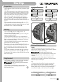
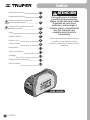
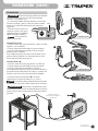
Safety Warnings for
Inverter Welders

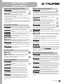
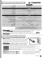
Negative
Connection
(
-
)
Positive
Connection
( + )
Work Piece
Grounding
Clamp
Transportation
Handle
Current
Adjustment
Control
Welding
Process
Selector
(SMAW or TIG)
Thermal
Protection
Light
ON
light
Switch
Electrode
Holder
6
Parts
ENGLISH
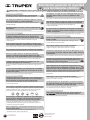
TIG soldering torch
AN-GRUPO1
(not included)
Power
Cord
Hammer-Brush
for Slag Removal
Carrying
Strap
Protective
Mask
To get better results use a Brand
adapter set ADA-SOLT, diffuser DIF-GRUPO1,
nozzle set BOQ-GRUPO1, cable set with
soldering clamp CAB-200A and
TIG soldering torch AN-GRUPO1

A
B
7
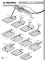
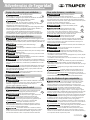
Installation (SMAW)
CD
ENGLISH
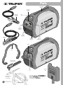
Set the adequate
electrode for the job
into the electrode holder
Metal
work
bench
Connections
C
To prevent electric shock, you need to see
information in section “Electrical Requirements” in pages 3
and 5.
• The fast connections of the electrode holder and the
grounding clamp are inserted and turned, one-quarter of
a turn in a clockwise direction in the front panel output
to get them properly secured.
• Press the upperarrow of the
process selector, so that the
welder works in SMAW (Covered
electrode) mode.
The upper led of the selector
will turn on.
Inverse Polarity (A)
• Connect the grounding clamp cable to the negative (-)
clamping screw outlet in the welder.
• Connect the grounding clamp (C) to the work piece.
• Connect the electrode holder cable to the positive (+)
clamping screw outlet in the welder.
This configuration produces more heat in the electrode thus,
producing more penetration with the basic electrodes, making
it ideal to solder thick pieces.
Direct Polarity (B)
• Connect the grounding clamp cable into the outlet (+).
• Connect the grounding clamp (C) to the work piece.
• Connect the electrode holder cable into the outlet (-).
This configuration generates more heat in the work piece
thus, producing less deformation and narrower seams,
making it ideal to solder thin pieces.
• Connect the feeding cable (D) working voltage network
(127 V / 220 V).
The welder automatically detects the working
voltage (No type of connection is necessary to be carried out).
Before using the welder shall be correctly
grounded. Do not uninstall the ground cable. It could cause
severe personal injury.
NOTE
WARNING
NOTE
CAUTION
Inverse Polarity
Direct Polarity
Led

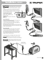
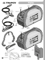
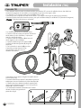
• This inverter welder can also be used to TIG welding. It is a high-quality soldering with non- consumable tungsten electrodes
and arc protected by inert gas like Argon or Helium.
• TIG welding is ideal for welding stainless steel, iron and copper.
• For this process, you will require a AN-GRUPO1 torch and a protection gas tank or can, not included.
• Press the lower arrow of the process selector, so that the welder works in TIG (Tungsten electrode) mode.
The lower led of the selector will turn on.
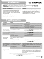
• The connection shall be direct polarity:
• Connect the grounding clamp cable to the positive
(+) clamping screw outlet in the welder and the
grounding clamp to the work piece.
• Connect the torch cable (A) to the welder
negative (-) clamping screw outlet.
• Connect the torch gas inlet (B) to the
protection gas regulator outlet valve (C).
• Turn the torch valve (D) to open the gas
until getting an approximate flow in
L/min of 6 times the electrode diameter.
8ENGLISH
Installation (TIG)
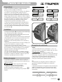
1 2 3
• To start the arc, support the nozzle in an angle onto the
work piece (1).
• Raise the torch without separating the nozzle from the
work piece to bring over the electrode to the work piece (2).
• When the electric arc starts lift the torch so that the
electrode tip is 0,08” away from the work piece (3). Start
soldering.
• It is recommended to keep the electrode 90° in the
vertical during the welding process
to guarantee the protection of the
gas.
TIG Connection
A
C
B
D
NOTE
Led

9
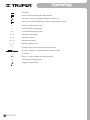
Start Up
ENGLISH
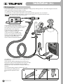
A
45° 45°
45°60°
60°
60°
BC
D
E
Electrode Replacement
SMAW:
• When the electrode has been consumed 0,4” to 0,8”
away from the electrode holder, it is necessary to replace it
with a new one to keep on welding.
• Electrodes are burned in high
temperature. Do not try to manipulate the remains of the
electrode with your hand. Set the remains in a metal
container.
• Open the electrode holder nipper to hold the new
electrode by the end that is not covered. Do not hold the
electrode by the covered part.
TIG:
• Tungsten electrodes shall be honed to guarantee the
good quality of the weld in its longitudinal direction.
• The tungsten electrode tip as a tendency to warp due to
heating. That is why, once the tip is not presenting the
recommended angle, it shall need to be honed again.
CAUTION
Soldering Current (A)
20
20 - 100
100 - 200
Electrode Angle
30º
60º - 90º
90º - 120º
Preparation
• Only experience, practice and care can guarantee a good
welding job.
• The factor intervening in the welding process are many:
required current, distance between the electrode and the
work piece, soldering speed and direction, thickness and
type of the material, the work piece position, electrode
angle and also gauge, type of material and electrode
covering. Therefore, is advisable that before welding to
carry out practice some in scrap material to determine
which are the specific requirements needed for the job to
perform.
• The area on the work piece where the soldering will be
applied shall be clean, free of rust and paint.
• Joints between sheets with gauges higher than 1/8” shall
be beveled to have an adequate weld (A).
Welding
• Set the switch (B) into the ON (I) position. The
indicating light will be illuminated.
• Turn the current adjusting control (C) until reaching the
amperes needed for the job.
• Hold the electrode holder or torch as comfortable as
possible. Bear in mind that during the welding process, the
angle, movement and distance regarding the work piece
shall be constant and uniform.
• Aim the electrode tip to the joint to be worked with to
generate the arc and start welding.
• Once the arc is lit start soldering keeping always the
electrode tip 0,08” away from the work piece. If you make
the weld having the electrode supported on the work
piece, it could adhere and the weld would have a low
quality.
• In case of overheating, the welder will stop functioning
and the thermal protection indicator light (D) will be lit.
Do not turn off the welder and wait until the indicator light
is off to use it again.
Slag Removal
• Upon finishing welding, use the wire brush included to
remove the slag from the weld bead surface.
• Wait until the slag has cooled down
and hardened to remove it.
• When hitting or brushing slag to remove it there can
be particles flying out. Wear eye protection and
keep bystanders away.
CAUTION

10 ENGLISH
Start Up
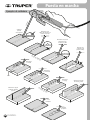
Examples of welding
Correctly
Applied Welding
Electrode
Electrode movement
too fast and / or
very low current.
Thin Sheets
Thick Sheets
Electrode movement
too slow and / or
very high current.
Spiral
movement.
Half-Moon
movement.
Zigzag
Movement.
Spot Weld.
Overlapped
Joint.
Angle welding
of thick sheets.
Angle welding of thin
sheets to thick sheets.
Electrode too
separated from
the work piece.
Bevel

11
Maintenance
ENGLISH
Troubleshooting
• Keep the welder least 11,8” away from any walls at to
allow air circulation.
• The welder will recuperate once the temperature gets
back to the right range to operate.
• The welder will recuperate once the temperature gets
back to the right range to operate.
• Go to a Authorized Service Center
to replace the potentiometer.
• Go to a Authorized Service Center
to replace the switch.
• Go to a Authorized Service Center
to repair the fan.
• Check all the connections.
• The welder will recuperate once the temperature is
back into the adequate range to operate.
• Go to a Authorized Service Center
to replace the switch.
• Replace the electrode holder with another one with more capacity.
• Replace the cable with another one within the requirements
(see page 3).
• Clean the rust accumulation and tighten the connections.
• Clean the rust accumulation and tighten the connections.
• There is no fault. It is normal that power supply gets cut when
the welder goes above its normal working temperature. Wait
until the temperature is back to the adequate working range to
turn it on again.
The thermal protection
light is ON.
The current adjusting
control is not working.
The fan is not working
or turns very slowly.
There is no open
circuit voltage.
The electrode holder is
too hot; connections +
and - are hot.
Energy source is off.
• The welder has no adequate ventilation.
• Environment temperature is too high.
• The welder has been used longer than the
recommended work cycle.
• The potentiometer is broken.
• Faulty switch.
• Faulty fan.
• Fault in the connections.
• High Voltage, low voltage or one phase is
missing.
• The welder is overheating.
• Faulty switch.
• The electrode capacity is too low.
• The cable gauge is too small.
• Loose connections.
• More resistance between the
electrode holder and the cable.
• The welder is hover-heated.
Problem Cause Solution
If after all the recommended actions have been carried out the problems persist,
contact a Authorized Service Center.
• The correct use and regular cleansing extend the useful life of the welder.
• Only qualified personnel shall carry out repairs. We recommend visiting a
Authorized Service Center to repair your welder, get supplies or accessories.
CAUTION
Regular Maintenance
• Clean dust from the welder with compressed air. If there
is too much dust present, clean immediately. Under
normal conditions clean once a year. If the welder is
exposed to a lot of dust, cleaning should be carried out
every three months.
• Altogether with cleaning make a checkup to assure there
are no loose parts or components in the welder.
• Keep the welder plug in good repair.
• The plug shall be checked before each use.
Storage
• In the event the welder will be stored a long period of
time, keep it in a dry, well ventilated place to prevent
humidity getting inside, or to generate rust or toxic gas.
Storage temperature vary between -13 °F to 131 °F and
relative humidity shall not be over 90%.

12
Symbology
ENGLISH
DC symbol
Electric arc manual welding with coated electrode
Inert metal – active gas welding, including the use of flux core
Input circuit, single-phase alternating current and rated frequency symbol
Work cycle symbol (service factor)
Nominal welding current symbol
Conventional load voltage symbol
Rated open circuit voltage
Rated power voltage
Maximum rated power
Maximum effective power
Protection degree (solid objects and water submersion)
Converter - transformer - single-phase static frequency rectifier
AC symbol
Electric-arc manual welding with coated electrodes
Gas shielded arc welding system
Tungsten inert gas welding
I2
U2
U0... V
U1... V
I1 max... A
I1 eff... A
IP
SMAW
TIG
1˜f1f2
1
~
60 Hz
X

13
ENGLISH
Authorized Service Centers
In the event of any problem contacting a Service Center, please see our webpage www.truper.com to get an
updated list, or call our toll-free numbers (800) 690-6990 or (800) 018-7873 to get information about the
nearest Authorized Service Center.
AGUASCALIENTES
BAJA
CALIFORNIA SUR
CAMPECHE
CHIAPAS
CHIHUAHUA
MÉXICO
CITY
COAHUILA
COLIMA
DURANGO
ESTADO DE
MÉXICO
GUANAJUATO
GUERRERO
HIDALGO
JALISCO
MICHOACÁN
MORELOS
NAYARIT
DE TODO PARA LA CONSTRUCCIÓN
GRAL. BARRAGÁN #1201, COL. GREMIAL, C.P. 20030,
AGUASCALIENTES, AGS. TEL.: 449 994 0537
SUCURSAL TIJUANA
AV. LA ENCANTADA, LOTE #5, PARQUE INDUSTRIAL EL
FLORIDO II, C.P 22244, TIJUANA, B.C.
TEL.: 664 969 5100
FIX FERRETERÍAS
FELIPE ÁNGELES ESQ. RUIZ CORTÍNEZ S/N, COL. PUEBLO
NUEVO, C.P. 23670, CD. CONSTITUCIÓN, B.C.S.
TEL.: 613 132 1115
TORNILLERÍA Y FERRETERÍA AAA
AV. ÁLVARO OBREGÓN #324, COL. ESPERANZA
C.P. 24080 CAMPECHE, CAMP. TEL.: 981 815 2808
FIX FERRETERÍAS
AV. CENTRAL SUR #27, COL. CENTRO, C.P. 30700,
TAPACHULA, CHIS. TEL.: 962 118 4083
SUCURSAL CHIHUAHUA
AV. SILVESTRE TERRAZAS #128-11, PARQUE INDUSTRIAL
BAFAR, CARRETERA MÉXICO CUAUHTÉMOC, C.P. 31415,
CHIHUAHUA, CHIH. TEL. 614 434 0052
FIX FERRETERÍAS
EL MONSTRUO DE CORREGIDORA, CORREGIDORA # 22,
COL. CENTRO, C.P. 06060, CUAUHTÉMOC, CDMX.
TEL: 55 5522 5031 / 5522 4861
SUCURSAL TORREÓN
CALLE METAL MECÁNICA #280, PARQUE INDUSTRIAL
ORIENTE, C.P. 27278, TORREÓN, COAH.
TEL.: 871 209 68 23
BOMBAS Y MOTORES BYMTESA DE MANZANILLO
BLVD. MIGUEL DE LA MADRID #190, COL. 16 DE
SEPTIEMBRE, C.P. 28239, MANZANILLO, COL.
TEL.: 314 332 1986 / 332 8013
TORNILLOS ÁGUILA, S.A. DE C.V.
MAZURIO #200, COL. LUIS ECHEVERRÍA, DURANGO,
DGO.TEL.: 618 817 1946 / 618 818 2844
SUCURSAL CENTRO JILOTEPEC
AV. PARQUE INDUSTRIAL #1-A, JILOTEPEC, C.P. 54240,
JILOTEPEC, EDO. DE MÉX.
TEL: 761 782 9101 EXT. 5728 Y 5102
CÍA. FERRETERA NUEVO MUNDO S.A. DE C.V.
AV. MÉXICO - JAPÓN #225, CD. INDUSTRIAL, C.P. 38010,
CELAYA, GTO. TEL.: 461 617 7578 / 79 / 80 / 88
CENTRO DE SERVICIO ECLIPSE
CALLE PRINCIPAL MZ.1 LT. 1, COL. SANTA FE, C.P. 39010,
CHILPANCINGO, GRO. TEL.: 747 478 5793
FERREPRECIOS S.A. DE C.V.
LIBERTAD ORIENTE #304 LOCAL 30, INTERIOR DE PASAJE
ROBLEDO, COL. CENTRO, C.P. 43600, TULANCINGO,
HGO. TEL.: 775 753 6615 / 775 753 6616
SUCURSAL GUADALAJARA
AV. ADOLFO B. HORN # 6800, COL: SANTA CRUZ DEL
VALLE, C.P.: 45655, TLAJOMULCO DE ZUÑIGA, JAL.
TEL.: 33 3606 5285 AL 90
FIX FERRETERÍAS
AV. PASEO DE LA REPÚBLICA #3140-A, COL.
EX-HACIENDA DE LA HUERTA, C.P. 58050, MORELIA,
MICH. TEL.: 443 334 6858
FIX FERRETERÍAS
CAPITÁN ANZURES #95, ESQ. JOSÉ PERDIZ, COL.
CENTRO, C.P. 62740, CUAUTLA, MOR.
TEL.: 735 352 8931
HERRAMIENTAS DE TEPIC
MAZATLAN #117, COL. CENTRO, C.P. 63000, TEPIC, NAY.
TEL.: 311 258 0540
SUCURSAL MONTERREY
CARRETERA LAREDO #300, 1B, MONTERREY PARKS
COLONIA PUERTA DE ANÁHUAC, C. P. 66052
ESCOBEDO, NL. TEL.: 81 8352 8791 / 81 8352 8790
FIX FERRETERÍAS
AV. 20 DE NOVIEMBRE #910, COL. CENTRO, C.P. 68300,
TUXTEPEC, OAX. TEL.: 287 106 3092
SUCURSAL PUEBLA
AV PERIFÉRICO #2-A, SAN LORENZO ALMECATLA,
C.P. 72710, CUAUTLACINGO, PUE.
TEL.: 222 282 8282 / 84 / 85 / 86
ARU HERRAMIENTAS S.A DE C.V.
AV. PUERTO DE VERACRUZ #110, COL. RANCHO DE
ENMEDIO, C.P. 76842, SAN JUAN DEL RÍO, QRO.
TEL.: 427 268 4544
FIX FERRETERÍAS
CARRETERA FEDERAL MZ. 46 LT. 3 LOCAL 2, COL EJIDAL,
C.P. 77710 PLAYA DEL CARMEN, Q.R.
TEL.: 984 267 3140
FIX FERRETERÍAS
AV. UNIVERSIDAD #1850, COL. EL PASEO, C.P. 78320,
SAN LUIS POTOSÍ, S.L.P. TEL.: 444 822 4341
SUCURSAL CULIACÁN
AV. JESÚS KUMATE SUR #4301, COL. HACIENDA DE LA
MORA, C.P. 80143, CULIACÁN, SIN.
TEL.: 667 173 9139 / 173 8400
FIX FERRETERÍAS
CALLE 5 DE FEBRERO #517, SUR LT. 25 MZ. 10, COL.
CENTRO, C.P. 85000, CD. OBREGÓN, SON.
TEL.: 644 413 2392
SUCURSAL VILLAHERMOSA
CALLE HELIO LOTES 1, 2 Y 3 MZ. #1, COL. INDUSTRIAL,
2A ETAPA, C.P. 86010, VILLAHERMOSA, TAB.
TEL.: 993 353 7244
VM ORINGS Y REFACCIONES
CALLE ROSITA #527 ENTRE 20 DE NOVIEMBRE Y GRAL.
RODRÍGUEZ, FRACC. REYNOSA, C.P. 88780, REYNOSA,
TAMS. TEL.: 899 926 7552
SERVICIOS Y HERRAMIENTAS INDUSTRIALES
PABLO SIDAR #132, COL . BARRIO DE SAN BARTOLOMÉ,
C.P. 90970, SAN PABLO DEL MONTE, TLAX.
TEL.: 222 271 7502
LA CASA DISTRIBUIDORA TRUPER
BLVD. PRIMAVERA. ESQ. HORTENSIA S/N, COL.
PRIMAVERA C.P. 93308, POZA RICA, VER.
TEL.: 782 823 8100 / 826 8484
SUCURSAL MÉRIDA
CALLE 33 #600 Y 602, LOCALIDAD ITZINCAB Y MULSAY,
MPIO. UMÁN, C.P. 97390, MÉRIDA, YUC.
TEL.: 999 912 2451
NUEVO LEÓN
OAXACA
PUEBLA
QUERÉTARO
QUINTANA ROO
SAN LUIS
POTOSÍ
SINALOA
SONORA
TABASCO
TAMAULIPAS
TLAXCALA
VERACRUZ
YUCATÁN

www.truper.com
02-2020
SOIN-120/160
Model Code Brand
1
YEAR
Warranty policy
13695
Delivery date:
This product, its parts and components have a one year warranty against defects in its
manufacture, operation and workmanship, except when: the product has been used in conditions
other than those recommended, or has not been operated according to the instructions, or has
been altered or repaired by personnel not authorized by . In order to make the
warranty valid or to purchase components and spare parts, you must present the product and its
proof of purchase at Av. San Isidro #110, Col. Industrial San Antonio, ALC. Azcapotzalco, C.P.
02760, CDMX, Mex. or at the store where you bought it, or at a service center
listed in the attached warranty policy and/or at www.truper.com. Transportation costs resulting
from compliance of this warranty will be covered by . For questions or comments,
call 800-690-6990.
Imported by: Truper, S.A. de C.V. , Parque Industrial #1, Jilotepec, Edo. de Méx.,
Méx. C.P. 54240, Made in China
Stamp of the business:
14 ENGLISH

40%
Ciclo de trabajo
Instructivo de
Soldadora
inversora
SOIN-120/160
Modelo Código
SOIN-120/160
Este instructivo es para:
13695
ATENCIÓN
ESPAÑOL
ENGLISH
Lea este Instructivo por completo
antes de usar la herramienta.

Í
ndice
2
Especificaciones técnicas
Requerimientos eléctricos
Advertencias generales de seguridad
para herramientas eléctricas
Advertencias de Seguridad para uso de
soldadoras inversoras
Partes
Instalación (SMAW)
Instalación (TIG)
Puesta en marcha
Mantenimiento
Solución de problemas
Simbología
Centros de Servicio Autorizados
Póliza de Garantía
Guarde este instructivo para futuras referencias.
Los gráficos de este instructivo son para
referencia, pueden variar del aspecto real de la
herramienta.
3
3
4
5
6
7
8
9
Para poder sacar el máximo
provecho de la herramienta,
alargar su vida útil, hacer válida
la garantía en caso de ser
necesario y evitar riesgos o
lesiones graves, es fundamental
leer este instructivo por
completo antes de usar la
herramienta.
ATENCIÓN
ESPAÑOL
11
11
12
13
14
SOIN-120/160

3
Especificaciones técnicas
ESPAÑOL
Si el cable de alimentación se daña, éste debe ser reemplazado por el fabricante o Centro de Servicio
Autorizado , con el fin de evitar algún riesgo de descarga o accidente considerable.
La construcción del aislamiento eléctrico de esta herramienta es alterado por salpicaduras o
derramamiento de líquidos durante su operación. No la exponga a la lluvia, líquidos y/o humedad.
Antes de obtener acceso a las terminales, todos los circuitos de alimentación deben ser desconectados.
ADVERTENCIA
ADVERTENCIA
ADVERTENCIA
ADVERTENCIA
13695
Código
Descripción
SOIN-120/160
Tensión
El cable de alimentación tiene sujeta-cables tipo: Y
La clase de construcción de la herramienta es: Aislamiento básico.
La clase de aislamiento térmico de los devanados del motor: Clase H.
No. de fases 2 Fases1 Fase
Corriente 39,5 A
Frecuencia 50 Hz / 60 Hz
Soldadora inversora
Entrada
Salida
127 V 220 V
Forzado con ventilador
Tensión de circuito abierto
15 A - 160 A15 A - 130 A
Rango de corriente
Tipo de enfriamiento
SMAW: 78 V c.c. TIG: 14,6 V c.c.SMAW: 90 V c.c. TIG: 14,6 V c.c.
IP21S
Grado IP
5,6 kg
Peso
40% 4 min de trabajo por 6 min de descanso.
Ciclo de trabajo
Aislamiento Clase I
12 AWG x 2C con temperatura de aislamiento de 105 °C
Conductores
7,7 kVA5 kVA
Capacidad nominal de entrada
3
Requerimientos eléctricos
En el caso de fallas o averias, la conexión a tierra provee una
trayectoria con resistencia mínima para la corriente eléctrica, lo que reduce el riesgo de
sufrir una descarga eléctrica. Esta herramienta está equipada con un cable eléctrico que
tiene un conductor a tierra y una clavija con conexión a tierra. La clavija debe estar
conectada a una entrada que se encuentre instalada y aterrizada de acuerdo con todos
los códigos locales.
No modifique la clavija provista. Si la clavija no ajusta a la
salida, adquiera la salida apropiada instalada por un electricista calificado.
• Si utiliza la soldadora junto a más herramientas con la misma tierra conéctelas en paralelo, nunca en serie.
• El calibre del cable conductor de tierra no puede ser de menor calibre que el cable de suministro eléctrico.
• La conexión a la fuente de energía debe realizarse por un profesional en electricidad.
• Confirme siempre que la tensión de la conexión de entrada, estipulada en la placa de información de
la soldadora, coincida con la tensión del suministro eléctrico.
• El calibre del cable del suministro eléctrico debe cumplir con los siguientes requisitos:
ATENCIÓN
ATENCIÓN
ATENCIÓN
* La corriente de fusión del fusible es el doble de su corriente nominal.
Interruptor
Fusible (Corriente nominal de trabajo)
Alambre eléctrico
30 A
30 A (*)
2,5 mm2
• En caso de requerir extensiones entre la soldadora y la
pieza de trabajo se debe aumentar el calibre del cable de
soldar para mantener la salida de energía de la soldadora
con una caída potencial no mayor a 4 V
ATENCIÓN
Los valores de salida especificada están dados a una temperatura de 20 ºC A temperaturas mayores el ciclo de trabajo puede reducirse.
Sistema de adaptación automática Bi-Voltaje

4
Advertencias generales de seguridad
para herramientas eléctricas
Área de trabajo
Mantenga el área de trabajo limpia y bien iluminada.
Las áreas desordenadas y obscuras son propensas a accidentes.
No maneje la herramienta en ambientes explosivos, como en
presencia de líquido, gas o polvo inflamables.
Las herramientas eléctricas producen chispas que pueden encender
material inflamable.
Mantenga alejados a los niños y curiosos cuando opere la
herramienta.
Las distracciones pueden hacer que pierda el control.
Seguridad eléctrica
La clavija de la herramienta debe coincidir con el tomacorrien-
te. Nunca modifique una clavija. No use ningún tipo de
adaptador para clavijas de herramientas puestas a tierra.
Clavijas modificadas y enchufes diferentes aumentan el riesgo de
choque eléctrico.
Evite el contacto del cuerpo con superficies puestas a tierra
como tuberías, radiadores, cocinas eléctricas y refrigeradores.
Hay un mayor riesgo de choque eléctrico si el cuerpo está puesto a tierra.
No exponga la herramienta a la lluvia o condiciones de humedad.
El agua que ingresa en la herramienta aumenta el riesgo de choque eléctrico.
No fuerce el cable. Nunca use el cable para transportar,
levantar o desconectar la herramienta. Mantenga el cable
lejos del calor, aceite, orillas afiladas o piezas en movimiento.
Los cables dañados o enredados aumentan el riesgo de choque eléctrico.
Cuando maneje una herramienta en exteriores, use una
extensión especial para uso en exteriores.
El uso de una extensión adecuada para exteriores reduce el riesgo de choque
eléctrico.
Si el uso de la herramienta en un lugar húmedo es inevitable,
use una alimentación protegida por un interruptor de circuito
de falla a tierra (GFCI).
El uso de un GFCI reduce el riesgo de choque eléctrico.
Seguridad personal
Esté alerta, vigile lo que está haciendo y use el sentido común
cuando maneje una herramienta. No la use si está cansado o
bajo la influencia de drogas, alcohol o medicamentos.
Un momento de distracción mientras maneja la herramienta puede
causar un daño personal.
Use equipo de seguridad. Use siempre protección para los ojos.
El uso de equipo de seguridad como lentes de seguridad, mascarilla antipolvo,
zapatos antideslizantes, casco y protección para los oídos en condiciones
apropiadas, reduce de manera significativa los daños personales.
Evite arranques accidentales. Asegúrese de que el interruptor
está en posición “apagado” antes de conectar a la fuente de
alimentación y/o a la batería o transportar la herramienta.
Transportar herramientas eléctricas con el dedo sobre el interruptor o
conectar herramientas eléctricas que tienen el interruptor en posición de
“encendido” puede causar accidentes.
Retire cualquier llave o herramienta de ajuste antes de arrancar
la herramienta eléctrica.
Las llaves o herramientas que quedan en las partes rotativas de la
herramienta pueden causar un daño personal.
No sobrepase su campo de acción. Mantenga ambos pies bien
asentados sobre el suelo y conserve el equilibrio en todo
momento.
Esto permite un mejor control de la herramienta en situaciones inesperadas.
Vista adecuadamente. No vista ropa suelta o joyas. Mantenga su
pelo, su ropa y guantes alejados de las piezas en movimiento.
La ropa o el pelo sueltos o las joyas pueden quedar atrapados en
las piezas en movimiento.
En caso de contar con dispositivos de extracción y recolección
de polvo conectados a la herramienta, verifique sus conexiones
y úselos correctamente.
El uso de estos dispositivos reduce los riesgos relacionados con el polvo.
Uso y cuidados de la herramienta
No fuerce la herramienta. Use la herramienta adecuada para el
trabajo a realizar.
La herramienta adecuada hace un trabajo mejor y más seguro cuando
se usa al ritmo para el que fue diseñada.
No use la herramienta si el interruptor no funciona.
Cualquier herramienta eléctrica que no pueda encenderse o
apagarse es peligrosa y debe repararse antes de ser operada.
Desconecte la herramienta de la fuente de alimentación y/o de
la batería antes de efectuar cualquier ajuste, cambiar accesorios
o almacenarla.
Estas medidas reducen el riesgo de arrancar la herramienta accidentalmente.
Almacene las herramientas fuera del alcance de los niños y no
permita su manejo por personas no familiarizadas con las
herramientas o con las instrucciones.
Las herramientas eléctricas son peligrosas en manos no entrenadas.
Déle mantenimiento a la herramienta. Compruebe que las
partes móviles no estén desalineadas o trabadas, que no
haya piezas rotas u otras condiciones que puedan afectar su
operación. Repare cualquier daño antes de usar la herramienta.
Muchos accidentes son causados por el escaso mantenimiento de las
herramientas.
Mantenga los accesorios de corte afilados y limpios.
Los accesorios de corte en buenas condiciones son menos probables de
trabarse y más fáciles de controlar.
Use la herramienta, sus componentes y accesorios de acuerdo
con estas instrucciones y de la manera prevista para el tipo de
herramienta, en condiciones de trabajo adecuadas.
El uso de la herramienta para aplicaciones diferentes para las que
está diseñada podría causar una situación de peligro.
Servicio
Repare la herramienta en un Centro de Servicio Autorizado
usando sólo piezas de repuesto idénticas.
Para mantener la seguridad de la herramienta.
¡ADVERTENCIA! Lea detenidamente todas las advertencias de seguridad y todas las instrucciones que se enlistan a continuación. La omisión de
alguna de ellas puede dar como resultado un choque eléctrico, incendio y/o daño serio. Conserve las advertencias y las instrucciones para futuras referencias.
ESPAÑOL
Esta herramienta cumple
con la Norma Oficial
Mexicana (NOM).

• Los vapores y gases producidos durante
el trabajo de soldadura son peligrosos para la salud. Trabaje en
sitios ventilados o con sistemas de ventilación adecuados.
• No respire los humos y gases del proceso
de soldadura, mantenga la cabeza alejada de las emanaciones.
•
Si la ventilación es pobre utilice un respirador
autónomo adecuado, ya que los gases de protección generados por la
soldadura pueden desplazar el aire y causar un accidente fatal.
• No opere la soldadora cerca de
desengrasantes, limpiadores o envases de aerosol, ya que el
calor y radiación del proceso de soldadura pueden reaccionar
con los vapores formando gases tóxicos.
• Evite realizar soldaduras en metales recubiertos
con plomo, zinc o cadmio, ya que generan gases tóxicos. De lo contrario
remueva el recubrimiento del área de soldadura, asegúrese de que el
área esté bien ventilada o utilice un respirador autónomo adecuado.
5
• Use careta para soldar
para proteger sus ojos y su cara cuando trabaje
con la soldadora. Asegúrese que el lente de sombra de la careta sea
el adecuado para el proceso de soldadura a realizar.
• Utilice guantes de cuero
especiales para soldar, así como petos y polainas de cuero.
• Utilice ropa de confección robusta y manga larga, de materiales
resistentes a la flama como lana o cuero.
• Utilice biombos o cortinas especiales para aislar el lugar de trabajo
del paso de transeúntes y protegerlos de las chispas, destellos y
escorias originados por el proceso de soldadura.
• Los bancos y mesas de trabajo donde descansen las piezas a
trabajar deberán de contar con orificios o ranuras que dejen pasar
con facilidad los residuos originados por el proceso de soldadura.
Advertencias de Seguridad
para uso de soldadoras inversoras
Equipo de protección para soldadura
ATENCIÓN
ATENCIÓN
ATENCIÓN
ADVERTENCIA
PELIGRO
ESPAÑOL
• Verifique que exista una conexión segura de los
cables de entrada y salida, que estén correctamente aislados y con sus
conexiones en buen estado (revise y elimine cualquier posibilidad de
corto circuito).
• Confirme que la soldadora tenga
una conexión a tierra confiable.
• No exponga la soldadora a la lluvia o condiciones
de humedad.
• Manténgase aislado de la pieza de trabajo y tierra
pisando tapetes aislantes y secos.
• Por ningún motivo toque los dos polos del circuito
de la soldadora (varilla y pieza de trabajo).
•
No intente ajustar la corriente de la soldadora
cuando esté realizando el trabajo de soldadura.
• Conecte la pinza de tierra a la pieza de trabajo lo
más cerca posible de la zona de soldadura para evitar que la corriente
fluya por grandes distancias y así eliminar la posibilidad de un corto
circuito.
• La pieza de trabajo debe hacer contacto con
la pinza de conexión a tierra antes de operar la soldadora y no debe
desconectarse hasta terminar de soldar, ya que puede recibir una
descarga y lesiones de gravedad.
• Desconecte la soldadora de la fuente de
alimentación antes de darle mantenimiento.
Para evitar descargas eléctricas
• Tenga siempre a mano un extintor
en buenas condiciones.
• No debe haber materiales inflamables o explosivos
en el área de trabajo (a no menos de 11 metros). No realice trabajos de
soldadura en lugares en donde las chispas puedan alcanzar o
caer sobre material inflamable o explosivo.
Para evitar incendios
ATENCIÓN
ATENCIÓN
ATENCIÓN
ATENCIÓN
ATENCIÓN
ATENCIÓN
PELIGRO
ADVERTENCIA
ADVERTENCIA
ADVERTENCIA
ADVERTENCIA
Para evitar riesgos para la salud
ADVERTENCIA
ADVERTENCIA
• Riesgo de choque eléctrico:
Un choque eléctrico o proveniente del electrodo de
soldadura puede causar la muerte. No soldar en la lluvia o en la nieve. No
tocar el electrodo con las manos desnudas. No utilice guantes húmedos o
dañados. Protección de personas contra choque eléctrico: aislarse de la pieza
de trabajo. No abra el envolvente del equipo.
No soldar sobre tambos o cualquier contenedor cerrado.
• Las chispas de soldadura pueden
causar explosión o incendio.
• Riesgo generado por el arco:
Las radiaciones de arco pueden quemar los ojos y dañar
la piel. Utilizar careta y gafas de protección. Utilizar protección
para los oídos y ropa de protección de manera que se proteja la piel hasta
la altura del cuello. Utilice protección completa del cuerpo.
• Riesgo inducido por campos
electromagnéticos: La corriente de soldadura produce
campo electromagnético. No utilizarla fuente de poder con implantes
médicos. Nunca enrollar los cables de la soldadura alrededor del cuerpo.
Colocar juntos y paralelos los dos cables de soldadura de forma que los
campos de cada uno se contrarresten.
• No utilizar la fuente de poder de soldadura para
descongelar tuberías.
• Nunca permita que personas sin experiencia
desmonten o regulen el aparato de soldar.
• Asegúrese que tanto el operador como la
soldadora estén fuera de la trayectoria de caída de las chispas y residuos
originados por el proceso de soldadura.
• La soldadora se debe operar en un sitio protegido del sol y la lluvia, alejada
de sitios donde haya vibraciones violentas.
• La soldadora se debe almacenar en un sitio sin humedad con un rango de
temperatura de -25 °C a +55 °C
• La base de la fuente de poder de la soldadura
debe estar inclinada como máximo 10º para evitar volcaduras.
• Debe haber un espacio de 30 cm alrededor de la soldadora para que tenga
buena ventilación.
• Asegúrese que ningún objeto extraño de metal esté
dentro de la soldadora.
• Cualquier problema con la soldadora que no
pueda ser resuelto por el operador haciendo los debidos ajustes para un
buen proceso de soldadura deben de ser solucionados en un Centro de
Servicio Autorizado , por ningún motivo intente abrir la
cubierta de la soldadora para realizar cualquier tipo de mantenimiento.
•
Los cilindros de gas comprimido son usados
ampliamente en muchos procesos de soldadura. Si no se almacenan,
manejan, inspeccionan y usan apropiadamente, los cilindros de gas
comprimido pueden ser mortales. Pueden explotar o convertirse en misiles,
emitiendo tal fuerza que pueden romper hasta paredes de ladrillo.
•
Inspeccione los cilindros en busca de corrosión
exterior, hendiduras, bultos, agujeros o pozos. Si no está seguro si alguna
imperfección observada es aceptable bajo estos lineamientos, entonces, deje
de usar el cilindro. Consulte la hoja de seguridad del gas antes de usarlo.
•
Muchos gases comprimidos no solamente representan
un peligro físico, sino también un peligro a la salud. Asegúrese de conocer
los peligros a la salud y de cómo protegerse a sí mismo. Siempre siga las
precauciones de uso y manejo provistas en el hoja de seguridad.
•
Nunca coloque los cilindros a un lado de recursos de
calor o cerca de flamas o puedan convertirse en parte de un circuito eléctrico
o los use para hacer tierra durante el proceso de soldadura eléctrica.
•
Use lentes de seguridad y una máscara protectora
cuando conecte y desconecte los reguladores y las líneas al cilindro.
•
Cierre la válvula del cilindro para liberar la presión
antes de remover el regulador del mismo y cuando el cilindro no se esté
usando. Los cilindros deben ser almacenados con una visible identificación y
con la tapa de la válvula de protección puesta.
Para evitar lesiones y accidentes
Uso de cilindros de gas comprimido
ATENCIÓN
ATENCIÓN
ATENCIÓN
ATENCIÓN
ATENCIÓN
ATENCIÓN
ATENCIÓN
ADVERTENCIA
ADVERTENCIA
ADVERTENCIA
ADVERTENCIA
ADVERTENCIA
ADVERTENCIA
ADVERTENCIA
ADVERTENCIA
ADVERTENCIA

Selector de
proceso de
soldadura
(SMAW o TIG)
Conexión
negativa ( - )
Conexión
positiva ( + )
Pinza para
aterrizar la
pieza de trabajo
Mango de
transporte
Control de
ajuste de
corriente
Antorcha para
soldadura TIG
AN-GRUPO1
(no incluida)
Cable de
alimentación
Cepillo-martillo
para retirar
escoria
Correa de
transporte
Luz de
encendido
Luz de
protección
térmica
Interruptor
Porta
electrodo
6
Partes
ESPAÑOL
Para mejores resultados utilice
juego de adaptadores ADA-SOLT,
difusor DIF-GRUPO1,
juego de boquillas BOQ-GRUPO1,
juego de cables con pinza para soldar
CAB-200A y antorcha para soldar TIG
AN-GRUPO1 marca
Careta
protectora

Polaridad inversa
A
Polaridad directa
B
D
7
Instalación (SMAW)
C
ESPAÑOL
Coloque un electrodo
adecuado para el trabajo en el
porta electrodo.
Mesa de
trabajo
de metal
Conexiones
Para evitar descargas eléctricas es necesario
consultar la información de la sección “Requerimientos
eléctricos” en las páginas 3 y 5.
• Las conexiones rápidas del porta electrodo y la pinza para
aterrizar se insertan y giran un cuarto de vuelta en sentido
horario en las salidas del pánel frontal para quedar bien
aseguradas.
• Presione la flecha superior del
selector de proceso, para que la
soldadora trabaje en modalidad
SMAW (Electrodo revestido).
El led superior del
selector se encenderá.
Polaridad inversa (A)
• Conecte el cable de la pinza para aterrizar al borne de salida
negativa (-) de la soldadora.
• Conecte la pinza para aterrizar (C) a la pieza de trabajo.
• Conecte el cable del porta electrodo al borne de salida
positiva (+) de la soldadora.
Esta configuración genera más calor en el electrodo, lo que
produce mayor penetración con electrodos básicos, que la
hacen ideal para soldar piezas gruesas.
Polaridad directa (B)
• Conecte el cable de la pinza para aterrizar a la salida (+).
• Conecte la pinza para aterrizar (C) a la pieza de trabajo.
• Conecte el cable del porta electrodo a la salida (-).
Esta configuración genera más calor en la pieza de trabajo, lo
que produce menor deformación de la pieza y cordones más
estrechos, que la hacen ideal para soldar piezas delgadas.
• Conecte el cable de alimentación (D) a la red de
alimentación a la tensión de trabajo (127 V / 220 V).
A La soldadura detecta automáticamente la tensión
de trabajo (no es necesario realizar ningún tipo de conexión).
Antes de usar la soldadora debe estar
correctamente puesta a tierra. No debe desinstalar el cable de
puesta a tierra ya que hacerlo propicia lesiones corporales de
gravedad.
NOTA
ATENCIÓN
ADVERTENCIA
C
NOTA
Led

8ESPAÑOL
Instalación (TIG)
• Para iniciar el arco apoye en ángulo la boquilla sobre la
pieza de trabajo (1).
• Levante la antorcha sin separar la boquilla de la pieza de
trabajo para acercar el electrodo a la pieza de trabajo (2).
• Cuando inicie el arco eléctrico levante la antorcha para
que la punta del electrodo quede a 2 mm de la pieza de
trabajo (3) y comience a soldar.
• Se recomienda mantener el electrodo a 90° vertical
durante el soldeo para garantizar la
protección del gas.
Conexión TIG
1 2 3
C
B
A
D
NOTA
• Esta soldadora inversora puede ser utilizada también para soldadura TIG: proceso de soldadura de muy alta calidad con
electrodos de tungsteno no consumibles y arco protegido por gas inerte como argón o helio.
• La soldadura TIG es ideal para soldar acero inoxidable, hierro y cobre.
• Para este proceso se requiere una antorcha AN-GRUPO1 y un tanque o lata de gas de protección (no incluidos).
• Presione la flecha inferior del selector de proceso, para que la soldadora trabaje en modalidad TIG (Electrodo de tungsteno)
El led inferior del selector se encenderá.
• La conexión debe hacerse en polaridad directa:
• Conecte el cable de la pinza para aterrizar al borne de
salida positiva (+) de la soldadora, y la pinza para
aterrizar a la pieza de trabajo.
• Conecte el cable de la antorcha (A) al borne de
salida negativa (-) de la soldadora.
• Conecte la entrada de gas de la antorcha (B) a
la válvula de salida del regulador (C) del gas de
protección.
• Gire la válvula de la antorcha (D) para abrir
el paso del gas, hasta obtener un flujo
aproximado en L/min de 6 veces el
diámetro del electrodo.
Led

9
Puesta en marcha
ESPAÑOL
A
45° 45°
45°60°
60°
60°
Retiro de escoria
• Al terminar el trabajo de soldado, utilice el cepillo de
alambre incluido para retirar la escoria de la superficie del
cordón de soldado.
• Espere a que la escoria se haya
enfriado y endurecido para poder retirarla.
• Al golpear o cepillar la escoria para retirarla
pueden salir partículas despedidas. Utilice
protección para los ojos y mantenga a las personas
alejadas.
ATENCIÓN
Preparativos
• Sólo con experiencia, práctica y cuidado se puede
garantizar un buen trabajo de soldadura.
• Los factores que intervienen en el proceso de soldadura
son muchos: corriente requerida, distancia entre el
electrodo y la pieza de trabajo, velocidad y dirección de
soldeo, grosor y tipo del material, posición de la pieza de
trabajo, ángulo del electrodo y además el calibre, material
y recubrimiento del electrodo. Por lo que es recomendable
que antes de realizar una soldadura realice prácticas en
material de desecho para determinar cuáles son los
requerimientos específicos del trabajo a realizar.
• El área de las piezas de trabajo donde será aplicada la
soldadura debe de estar limpia, libre de óxido y pintura.
• Las uniones entre láminas con calibres mayores de 3,1
mm (1/8”) deben de ser biseladas para que la soldadura
sea adecuada (A).
Soldadura
• Coloque el interruptor (B) en posición de encendido (I);
la luz indicadora de energía se encenderá.
• Gire el control de ajuste de corriente (C) hasta alcanzar
el amperaje requerido para el trabajo.
• Sostenga el porta electrodo o antorcha de la manera más
cómoda posible. Tome en cuenta que durante el proceso
de soldado, el ángulo, movimiento y distancia con
respecto a la pieza de trabajo deben de ser constantes y
uniformes.
• Dirija la punta del electrodo hacia la unión a trabajar para
generar el arco eléctrico y comience a soldar.
• Una vez que el arco encienda comience a soldar,
manteniendo siempre la punta del electrodo a 2 mm de la
pieza de trabajo. Si realiza la soldadura con el electrodo
apoyado en la pieza de trabajo podría adherirse y la
soldadura sería de mala calidad.
• En caso de sobrecalentamiento la soldadora dejara de
funcionar y la luz indicadora de protección térmica (D) se
encenderá, no apague la soldadora y espere a que la luz
indicadora se apague para volverla a utilizar.
Reemplazo de electrodo
SMAW:
• Cuando el electrodo se ha consumido de 1 cm a 2 cm
del porta electrodo, es necesario cambiarlo por uno nuevo
para poder seguir soldando.
• El electrodo se quema a alta
temperatura. No intente manipular los restos del electrodo
con la mano. Ponga los restos en un contenedor de metal.
• Abra la tenaza del porta electrodo para sostener el
electrodo nuevo por el extremo sin recubrimiento. No
sostenga el electrodo por la parte recubierta.
TIG:
• Los electrodos de Tungsteno deben ser afilados para
garantizar la calidad de la soldadura en su dirección
longitudinal.
• La punta del electrodo de Tungsteno tiende a deformarse
debido al calentamiento, es por eso que una vez que la
punta no presente el ángulo recomendado, debe afilarse
nuevamente.
ATENCIÓN
Corriente de soldadura (A)
20
20 - 100
100 - 200
Ángulo de electrodo
30º
60º - 90º
90º - 120º
BC
D
E

10 ESPAÑOL
Puesta en marcha
Ejemplos de soldadura
Soldadura
aplicada
correctamente
Electrodo
Movimiento muy
rápido del electrodo y/o
corriente muy baja.
Láminas delgadas
Láminas gruesas
Movimiento muy lento
del electrodo y/o
corriente muy alta.
Movimiento
en espiral.
Movimiento
en media luna.
Movimiento
en zigzag.
Soldadura
por puntos.
Unión
traslapada.
Soldadura en ángulo
de láminas gruesas.
Soldadura en ángulo
de láminas delgada
a gruesa.
Electrodo muy
separado de la
pieza de trabajo.
Bisel

11
Mantenimiento
ESPAÑOL
Solución de problemas
• Mantenga la soldadora apartada de cualquier pared al
menos 30 cm para permitir que el aire circule.
• La soldadora se recuperará una vez que la temperatura
regresa al rango adecuado para operar.
• La soldadora se recuperará una vez que la temperatura
regresa al rango adecuado para operar.
• Acuda a un Centro de Servicio Autorizado
para reemplazar el potenciómetro.
• Acuda a un Centro de Servicio Autorizado
para remplazar el interruptor.
• Acuda a un Centro de Servicio Autorizado
para reparar el ventilador.
• Revise las conexiones.
• La soldadora se recuperará una vez que la temperatura
regresa al rango adecuado para operar.
• Acuda a un Centro de Servicio Autorizado
para remplazar el interruptor.
• Reemplace el porta electrodo por otro de mayor capacidad.
• Reemplace el cable por otro dentro de los requerimientos
(consulte la página 3).
• Limpie la acumulación de óxido y apriete las conexiones.
• Limpie la acumulación de óxido y apriete las conexiones.
• No hay falla. Es normal que el suministro de energía se
corte cuando la soldadora sobrepasa su temperatura normal
de trabajo. Espere a que la temperatura regrese a al rango
adecuado de trabajo para poder encenderla de nuevo.
La luz de protección
térmica está
encendida.
El control de ajuste de
corriente no funciona.
El ventilador no
funciona o gira muy
lentamente.
No hay tensión de
circuito abierto.
El porta electrodo se
calienta demasiado;
las conexiones + y - se
calientan.
La fuente de energía
se corta.
• La soldadora no cuenta con ventilación
adecuada.
• Temperatura ambiente muy alta.
• La soldadora se utilizó por más tiempo
del recomendado en su ciclo de trabajo.
• El potenciómetro está roto.
• Interruptor descompuesto.
• Ventilador descompuesto.
• Falla en las conexiones.
• Tensión alta, tensión baja o falta una fase.
• La soldadora se está sobrecalentando.
• Interruptor descompuesto.
• La capacidad del porta electrodo es
muy baja.
• La medida del cable es muy pequeña.
• Conexiones flojas.
• Mayor resistencia entre el porta
electrodo y el cable.
• La soldadora se ha sobrecalentado.
Problema Causa Solución
Si los problemas persisten a pesar de realizar las acciones correctivas recomendadas,
contacte a un Centro de Servicio Autorizado .
• El uso correcto y una limpieza regular prolongan la vida útil de la soldadora.
• Sólo personal calificado debe hacer las reparaciones. Se recomienda visitar un Centro de Servicio
Autorizado para reparar la soldadora, adquirir suministros o accesorios.
ATENCIÓN
Mantenimiento regular
• Se debe limpiar el polvo de la soldadora con aire
comprimido. En caso haber mucho polvo, se debe limpiar
de inmediato. Bajo condiciones normales se requiere
limpieza una vez al año, en caso de que la soldadora esté
expuesta a mucho polvo, la limpieza debe realizarse cada
tres meses.
• Junto con la limpieza se debe realizar una revisión para
asegurar que no haya partes o componentes sueltos en la
soldadora.
• Mantenga la clavija del cable de la soldadora en buen
estado.
• La clavija debe revisarse antes de cada uso.
Almacenamiento
• En caso que la soldadora vaya a estar almacenada por un
periodo largo de tiempo, se debe mantener en un sitio
seco y bien ventilado para evitar que le entre humedad, se
genere óxido o gases tóxicos. La temperatura de
almacenaje varía de -25 °C a +55 °C, y la humedad relativa
no debe ser superior a 90%.

12
Simbología
ESPAÑOL
Corriente directa
Soldadura manual por arco eléctrico con electrodo revestido
Soldadura de metal inerte y gas activo incluyendo el uso de núcleo fundente
Circuito de entrada, símbolo para corriente alterna monofásica y frecuencia nominal
Símbolo del ciclo de trabajo (factor de servicio)
Símbolo de la corriente de la soldadura nominal
Símbolo de la tensión de carga convencional
Tensión nominal de circuito abierto
Tensión nominal de alimentación
Corriente nominal máxima de alimentación
Corriente de alimentación máxima efectiva
Grado de protección (objetos sólidos e ingreso al agua)
Convertidor - transformador - rectificador monofásico de frecuencia estática
Símbolo de corriente alterna
Soldadura manual por arco eléctrico con electrodos revestidos
Sistema de soldadura al arco con protección gaseosa
Soldadura con gas inerte de tungsteno
I2
U2
U0... V
U1... V
I1 max... A
I1 eff... A
IP
SMAW
TIG
1˜f1f2
1
~
60 Hz
X

13
ESPAÑOL
Centros de Servicio Autorizados
En caso de tener algún problema para contactar un Centro de Servicio consulte nuestra página www.truper.com
donde obtendrá un listado actualizado, o llame al teléfono: (800) 690-6990 ó (800) 018-7873 donde le
informarán cuál es el Centro de Servicio Autorizado más cercano.
AGUASCALIENTES
BAJA
CALIFORNIA SUR
CAMPECHE
CHIAPAS
CHIHUAHUA
CIUDAD DE
MÉXICO
COAHUILA
COLIMA
DURANGO
ESTADO DE
MÉXICO
GUANAJUATO
GUERRERO
HIDALGO
JALISCO
MICHOACÁN
MORELOS
NAYARIT
DE TODO PARA LA CONSTRUCCIÓN
GRAL. BARRAGÁN #1201, COL. GREMIAL, C.P. 20030,
AGUASCALIENTES, AGS. TEL.: 449 994 0537
SUCURSAL TIJUANA
AV. LA ENCANTADA, LOTE #5, PARQUE INDUSTRIAL EL
FLORIDO II, C.P 22244, TIJUANA, B.C.
TEL.: 664 969 5100
FIX FERRETERÍAS
FELIPE ÁNGELES ESQ. RUIZ CORTÍNEZ S/N, COL. PUEBLO
NUEVO, C.P. 23670, CD. CONSTITUCIÓN, B.C.S.
TEL.: 613 132 1115
TORNILLERÍA Y FERRETERÍA AAA
AV. ÁLVARO OBREGÓN #324, COL. ESPERANZA
C.P. 24080 CAMPECHE, CAMP. TEL.: 981 815 2808
FIX FERRETERÍAS
AV. CENTRAL SUR #27, COL. CENTRO, C.P. 30700,
TAPACHULA, CHIS. TEL.: 962 118 4083
SUCURSAL CHIHUAHUA
AV. SILVESTRE TERRAZAS #128-11, PARQUE INDUSTRIAL
BAFAR, CARRETERA MÉXICO CUAUHTÉMOC, C.P. 31415,
CHIHUAHUA, CHIH. TEL. 614 434 0052
FIX FERRETERÍAS
EL MONSTRUO DE CORREGIDORA, CORREGIDORA # 22,
COL. CENTRO, C.P. 06060, CUAUHTÉMOC, CDMX.
TEL: 55 5522 5031 / 5522 4861
SUCURSAL TORREÓN
CALLE METAL MECÁNICA #280, PARQUE INDUSTRIAL
ORIENTE, C.P. 27278, TORREÓN, COAH.
TEL.: 871 209 68 23
BOMBAS Y MOTORES BYMTESA DE MANZANILLO
BLVD. MIGUEL DE LA MADRID #190, COL. 16 DE
SEPTIEMBRE, C.P. 28239, MANZANILLO, COL.
TEL.: 314 332 1986 / 332 8013
TORNILLOS ÁGUILA, S.A. DE C.V.
MAZURIO #200, COL. LUIS ECHEVERRÍA, DURANGO,
DGO.TEL.: 618 817 1946 / 618 818 2844
SUCURSAL CENTRO JILOTEPEC
AV. PARQUE INDUSTRIAL #1-A, JILOTEPEC, C.P. 54240,
JILOTEPEC, EDO. DE MÉX.
TEL: 761 782 9101 EXT. 5728 Y 5102
CÍA. FERRETERA NUEVO MUNDO S.A. DE C.V.
AV. MÉXICO - JAPÓN #225, CD. INDUSTRIAL, C.P. 38010,
CELAYA, GTO. TEL.: 461 617 7578 / 79 / 80 / 88
CENTRO DE SERVICIO ECLIPSE
CALLE PRINCIPAL MZ.1 LT. 1, COL. SANTA FE, C.P. 39010,
CHILPANCINGO, GRO. TEL.: 747 478 5793
FERREPRECIOS S.A. DE C.V.
LIBERTAD ORIENTE #304 LOCAL 30, INTERIOR DE PASAJE
ROBLEDO, COL. CENTRO, C.P. 43600, TULANCINGO,
HGO. TEL.: 775 753 6615 / 775 753 6616
SUCURSAL GUADALAJARA
AV. ADOLFO B. HORN # 6800, COL: SANTA CRUZ DEL
VALLE, C.P.: 45655, TLAJOMULCO DE ZUÑIGA, JAL.
TEL.: 33 3606 5285 AL 90
FIX FERRETERÍAS
AV. PASEO DE LA REPÚBLICA #3140-A, COL.
EX-HACIENDA DE LA HUERTA, C.P. 58050, MORELIA,
MICH. TEL.: 443 334 6858
FIX FERRETERÍAS
CAPITÁN ANZURES #95, ESQ. JOSÉ PERDIZ, COL.
CENTRO, C.P. 62740, CUAUTLA, MOR.
TEL.: 735 352 8931
HERRAMIENTAS DE TEPIC
MAZATLAN #117, COL. CENTRO, C.P. 63000, TEPIC, NAY.
TEL.: 311 258 0540
SUCURSAL MONTERREY
CARRETERA LAREDO #300, 1B, MONTERREY PARKS
COLONIA PUERTA DE ANÁHUAC, C. P. 66052
ESCOBEDO, NL. TEL.: 81 8352 8791 / 81 8352 8790
FIX FERRETERÍAS
AV. 20 DE NOVIEMBRE #910, COL. CENTRO, C.P. 68300,
TUXTEPEC, OAX. TEL.: 287 106 3092
SUCURSAL PUEBLA
AV PERIFÉRICO #2-A, SAN LORENZO ALMECATLA,
C.P. 72710, CUAUTLACINGO, PUE.
TEL.: 222 282 8282 / 84 / 85 / 86
ARU HERRAMIENTAS S.A DE C.V.
AV. PUERTO DE VERACRUZ #110, COL. RANCHO DE
ENMEDIO, C.P. 76842, SAN JUAN DEL RÍO, QRO.
TEL.: 427 268 4544
FIX FERRETERÍAS
CARRETERA FEDERAL MZ. 46 LT. 3 LOCAL 2, COL EJIDAL,
C.P. 77710 PLAYA DEL CARMEN, Q.R.
TEL.: 984 267 3140
FIX FERRETERÍAS
AV. UNIVERSIDAD #1850, COL. EL PASEO, C.P. 78320,
SAN LUIS POTOSÍ, S.L.P. TEL.: 444 822 4341
SUCURSAL CULIACÁN
AV. JESÚS KUMATE SUR #4301, COL. HACIENDA DE LA
MORA, C.P. 80143, CULIACÁN, SIN.
TEL.: 667 173 9139 / 173 8400
FIX FERRETERÍAS
CALLE 5 DE FEBRERO #517, SUR LT. 25 MZ. 10, COL.
CENTRO, C.P. 85000, CD. OBREGÓN, SON.
TEL.: 644 413 2392
SUCURSAL VILLAHERMOSA
CALLE HELIO LOTES 1, 2 Y 3 MZ. #1, COL. INDUSTRIAL,
2A ETAPA, C.P. 86010, VILLAHERMOSA, TAB.
TEL.: 993 353 7244
VM ORINGS Y REFACCIONES
CALLE ROSITA #527 ENTRE 20 DE NOVIEMBRE Y GRAL.
RODRÍGUEZ, FRACC. REYNOSA, C.P. 88780, REYNOSA,
TAMS. TEL.: 899 926 7552
SERVICIOS Y HERRAMIENTAS INDUSTRIALES
PABLO SIDAR #132, COL . BARRIO DE SAN BARTOLOMÉ,
C.P. 90970, SAN PABLO DEL MONTE, TLAX.
TEL.: 222 271 7502
LA CASA DISTRIBUIDORA TRUPER
BLVD. PRIMAVERA. ESQ. HORTENSIA S/N, COL.
PRIMAVERA C.P. 93308, POZA RICA, VER.
TEL.: 782 823 8100 / 826 8484
SUCURSAL MÉRIDA
CALLE 33 #600 Y 602, LOCALIDAD ITZINCAB Y MULSAY,
MPIO. UMÁN, C.P. 97390, MÉRIDA, YUC.
TEL.: 999 912 2451
NUEVO LEÓN
OAXACA
PUEBLA
QUERÉTARO
QUINTANA ROO
SAN LUIS
POTOSÍ
SINALOA
SONORA
TABASCO
TAMAULIPAS
TLAXCALA
VERACRUZ
YUCATÁN

www.truper.com
02-2020
Sello del establecimiento comercial:
Fecha de entrega:
Modelo Código Marca
1
AÑO
SOIN-120/160 13695
Póliza de Garantía
Este producto, sus piezas y componentes están garantizados por un año contra defectos de
fabricación, funcionamiento y mano de obra, excepto cuando: el producto haya sido usado en
condiciones distintas a las recomendadas, o no se haya operado de acuerdo al instructivo, o
haya sido alterado o reparado por personal no autorizado por . Para hacer
válida la garantía o adquirir piezas y componentes deberá presentar el producto y su
comprobante de compra en Av. San Isidro #110, Col. Industrial San Antonio, Alc. Azcapotzalco,
C.P. 02760, CDMX, Méx. o en el establecimiento donde lo compró, o en algún Centro de
Servicio de los enlistados en el anexo de la póliza de garantía y/o en
www.truper.com . Los gastos de transportación que resulten para su cumplimiento serán
cubiertos por . Para dudas o comentarios, llame al 800-690-6990.
Importado por: Truper, S.A. de C.V. , Parque Industrial #1, Jilotepec, Edo. de Méx.,
Méx. C.P. 54240, Hecho en China
14 ESPAÑOL
-
 1
1
-
 2
2
-
 3
3
-
 4
4
-
 5
5
-
 6
6
-
 7
7
-
 8
8
-
 9
9
-
 10
10
-
 11
11
-
 12
12
-
 13
13
-
 14
14
-
 15
15
-
 16
16
-
 17
17
-
 18
18
-
 19
19
-
 20
20
-
 21
21
-
 22
22
-
 23
23
-
 24
24
-
 25
25
-
 26
26
-
 27
27
-
 28
28


Truper COMBO-120/160 El manual del propietario
- Categoría
- Herramientas eléctricas
- Tipo
- El manual del propietario
En otros idiomas
- English: Truper COMBO-120/160 Owner's manual
Documentos relacionados
Otros documentos
-
Forney 298 100 ST Easy Weld Manual de usuario
-
Campbell Hausfeld ARCITECH WS2100 Manual de usuario
-
-
-
-
-
-
-
Husky PIONEERST80 Guía del usuario
-
KNOVA KN INW-130 El manual del propietario