


34007115EN/AA - Page 3
Introduction
Thank you for selecting an MGE UPS SYSTEMS product to protect your electrical equipment.
The Pulsar Evolution range has been designed with the utmost care. We recommend that you take the time to read this
manual to take full advantage of the many features of your UPS.
MGE UPS SYSTEMS pays great attention to the environmental impact of its products. Measures that have made Pulsar
Evolution a reference in environmental protection include:
◗ the eco-design approach used in product development,
◗ recycling of Pulsar Evolution at the end of its service life.
To discover the entire range of MGE UPS SYSTEMS products and the options available for the Pulsar Evolution range,
we invite you to visit our web site at www.mgeups.com or contact your MGE UPS SYSTEMS representative.

Page 4 - 34007115EN/AA
Foreword
Using this document
Important instructions that must always be followed.
Information, advice, help.
Visual indication.
Action.
Audio indication.
In the illustrations on the following pages, the symbols below are used:
LED off.
LED on.
LED flashing.
Information may be found in two ways, using:
◗ the contents;
◗ the index.
Pictograms

34007115EN/AA - Page 5
Contents
1. Presentation
1.1 Overall view ................................................................................................................................. 7
Tower position ................................................................................................................................. 7
Rack position .................................................................................................................................. 7
1.2 Back ............................................................................................................................................. 8
1.3 Control panel ................................................................................................................................. 9
2. Installation
2.1 Unpacking and parts check ....................................................................................................... 10
2.2 Upright installation (tower position) ......................................................................................... 11
2.3 Flat installation (rack position) .................................................................................................. 12
2.4 Connecting the protected equipment ....................................................................................... 13
2.5 Connection to the RS232 or USB communications port (optional)......................................... 14
2.6 Connection to the data-line protection port (optional) ............................................................. 14
2.7 Installation of the communications-card option ...................................................................... 15
3. Operation
3.1 Start-up ........................................................................................................................................ 16
3.2 Shift to booster or fader mode (during voltage variations in the AC-input power)..................... 16
3.3 Operation on battery power (following failure of AC-input power) ............................................. 17
Transfer to battery power .............................................................................................................. 17
Threshold for the low-battery warning...........................................................................................17
3.4 Personalisation (optional) ........................................................................................................... 18
Function ........................................................................................................................................ 18
ON / OFF conditions tab ............................................................................................................... 18
Battery tab..................................................................................................................................... 18
Voltage-thresholds tab .................................................................................................................. 19
Sensitivity tab ................................................................................................................................ 19
4. Maintenance
4.1 Trouble-shooting......................................................................................................................... 20
4.2 Replacement of the battery module .......................................................................................... 21
5. Environment ..................................................................................................................................... 23

Page 6 - 34007115EN/AA
Contents
6. Appendices
6.1 Technical data ............................................................................................................................. 24
Simplified diagram ........................................................................................................................ 24
Technical characteristics ............................................................................................................... 25
Examples of battery backup times ................................................................................................26
6.2 Glossary....................................................................................................................................... 27
6.3 Index............................................................................................................................................. 28


Page 8 - 34007115EN/AA
1 2
IN OUT
Ue/In/Eing 230V/16A Max
DATA LINE PROTECTION
AB
1
2
Us/Out/Ausg I max 13A
AB
TO BATTERY
CABINET
RS232
1 2
IN OUT
Ue/In/Eing 230V/10A Max
TO BATTERY
CABINET
DATA LINE PROTECTION
Us/Out/Ausg I max 10A
RS232
1. Presentation
1.2 Back
Pulsar Evolution 3000 / 3000 XL
Pulsar Evolution 2200
USB communications port.
RS232 communications port.
Connector for automatic detection of an
additional battery module.
Data-line protection.
Slot for communications-card option.
Connector for an additional battery
module.
Output circuit breakers.
Four outlets for direct connection of
protected equipment.
Two groups of two programmable
outlets (groups 1 and 2).
Input circuit-breaker.
Socket for connection to AC-power
source.
Battery module connectors (to the UPS
or to other battery modules).
Connectors for automatic detection of
additional battery modules.
Circuit breaker for battery ON/OFF and
protection.
1
2
3
4
5
6
7
9
8
10
11
12 14
EXB additional battery module 12
13
14
13 12
7
1234 115 1098
12
6
1234 115 109
8
12
6

34007115EN/AA - Page 9
12
%
%
1.3 Control panel
Bargraph indicating percent load at output.
Group 1 programmable outlets supplied with power.
Iluminated ON/OFF button for the outlets.
Group 2 programmable outlets supplied with power.
Operation on battery power.
15
16
17
20
19
23
22
18
21
1. Presentation
UPS fault.
Battery fault.
Overload.
Booster or fader mode.
Bargraph indicating the battery charge level.
0 to 25%.
26 to 50%.
51 to 75%.
76 to 100%.

Page 10 - 34007115EN/AA
2. Installation
2.1 Unpacking and parts check
Cord for connection to the AC-power source for 3000/3000 XL versions only (for the 2200 version, use the power cord
of the protected equipment).
Two cords for connection of the protected equipment.
RS232 communications cable.
USB communications cable.
Telescopic rails for mounting in 19" bay with mounting hardware.
Two securing systems for equipment power cords.
CD-ROM with the Solution-Pac and UPS Driver software.
Product documentation.
Two supports for the upright position.
27
28
29
25
24
25
26
27
28
26
24
29
31
32
31
32
30
30
P U L S A R
Evolution
3 0 0 0


34007115EN/AA - Page 13
Ue/In/Eing 230V/10A Max
1 2
Us/Out/Ausg I max 10A
2.4 Connecting the protected equipment
Check that the indications on the rating plate on the back of the UPS correspond to your AC-power system and to
the actual electrical consumption of all the equipment to be connected to the UPS.
1 - Remove the power cord supplying the
equipment to be protected.
2 - Pulsar Evolution 2200: Connect the
power cord (1) just removed from the
equipment to the AC-power socket 11 and
then to the AC-power wall outlet.
- Pulsar Evolution 3000/3000 XL: Connect
the supplied power cord 24 (250 V, 16 A) to
the AC-power socket 11 and then to the
AC-power wall outlet.
3 - Connect the protected equipment to the
UPS using the two cords 25 . It is advised
to connect priority loads to the four standard
outlets 8 and any non-priority loads to the
four programmable outlets 9 (in groups of
two outlets).
If the UPS is connected to a
computer running MGE
communications software, it is
possible to program the
interruption of power to the
programmable outlets 9 during
operation on battery power, thus
reserving backup power for the
priority loads.
4 - Lock the connections using the securing
system 29 .
25
8
9
1
2
2. Installation
11
29
As soon as the UPS is energised, the battery begins charging. Eight hours are required to charge to the full rated
backup time.
Pulsar Evolution 3000 XL: At least one EXB additional battery module must be connected to the UPS because it does not
have internal batteries. See the EXB battery-module installation manual (Doc. no. 3400711600) for information on making
the connections.
(1) Make sure the cord has the following
characteristics: 250 V, 10 A, cross-sectional area 1
mm2, type HO5.

Page 14 - 34007115EN/AA
IN OUT
DATA LINE PROTECTION
TO BATTERY
CABINET
RS232
2. Installation
2.5 Connection to the RS232 or USB communications port (optional)
1 - Connect the RS232 26 or USB 27
communications cable to the serial port or
the USB port on the computer.
2 - Connect the other end of the
communications cable 26 or 27 to the
RS232 2 or USB 1 communications
port on the UPS.
The UPS can now communicate with all
MGE UPS SYSTEMS supervision, set-up or
safety software.
26
27
The RS232 and USB
communications ports cannot
operate simultaneously.
2.6 Connection to the data-line protection port (optional)
The data-line protection function on the UPS
eliminates overvoltages flowing on the
computer-network lines.
Simply connect the line to be protected to
the UPS using the data-line protection
connectors (IN and OUT) as indicated
opposite (RJ45 cables not supplied).
1
2
IN OUT
TO BATTERY
CABINET
DATA LINE PROTECTION
RS232

34007115EN/AA - Page 15
2. Installation
2.7 Installation of the communications-card option
1 - Remove the slot cover 5 secured by
two screws.
2 - Insert the card in the slot.
3 - Secure the cover with the two screws.
Slot for the communications-card
option.
5
IN OUT
TO BATTERY
CABINET
DATA LINE PROTECTION
RS232
It is not necessary to shut down the UPS to install the communications card.

Page 16 - 34007115EN/AA
12
%
%
3. Operation
3.1 Start-up
15
16
17
Press the ON / OFF button 15 .
The buzzer beeps and all the LEDs come ON.
The buzzer beeps twice during the self-test, then button 15 remains
ON, indicating that the outlets are supplied with power.
- AC power is present: Only button 15 is ON. The protected
equipment is supplied by the AC-power source.
- AC power is absent: Button 15 and LED 16 are ON. The protected
equipment is supplied by the UPS, operating on battery power.
All the connected equipment is supplied with power.
12
%
%
3.2 Shift to booster or fader mode
(during voltage variations in the AC-input power)
21
The booster and fader functions maintain the output voltage supplied by
the UPS within close tolerances around the rated value even if
significant voltage variations occur in the AC-input power. This avoids
calling on battery power.
The values defining the voltage range may be set using the UPS Driver
software.
During operation in booster or fader mode, LED 21 is ON, signalling a
significant voltage variation in the AC-input power.
If button 15 or LED 16 are not ON or if LED 17 is ON, there is a fault (see section 4.1).
Note: The battery is charged as soon as the UPS is connected to the AC-power source, even if button 15 is in the OFF
position.

34007115EN/AA - Page 17
12
%
%
12
%
%
3. Operation
3.3 Operation on battery power (following failure of AC-input power)
Transfer to battery power
The AC-input power is out of tolerances, LED 16 goes ON.
During operation on battery power, the buzzer beeps every ten seconds.
The equipment connected to the UPS is supplied by the battery.
Threshold for the low-battery warning
When the threshold is reached, the buzzer beeps every three seconds.
The low-battery warning threshold can be set by the user, with the “UPS
Driver” software.
There is very little remaining battery backup time. Close all
applications because UPS automatic shutdown is imminent.
When the battery reaches the end of its backup time, the UPS shuts
down and all the LEDs go OFF.
The equipment is no longer supplied with power.
16
The UPS automatically restarts when power returns.
If the UPS does not restart, check that the “automatic restart when power returns” function has not been disabled (see
section 3.4 Personalisation).
16

Page 18 - 34007115EN/AA
3. Operation
3.4 Personalisation (optional)
Function
Configurable function
Automatic restart
Cold start
Forced reboot
Energy saving
UPS ON / OFF via software
Default setting
Enabled
Enabled
Enabled
Disabled
Enabled
Personalisation parameters can be set and modified using the UPS Driver software installed on a computer that is
connected to the UPS (see section 2.5 Connection to the RS232 communications port).
Check that the RS232 26 communications cable is connected.
UPS Driver installation:
1 - Insert the Solution-Pac CD-ROM containing the UPS Driver software in the drive of a PC running Windows.
2 - Open the Windows File manager or Explorer and select the CD-ROM drive.
3 - Double-click "\Emb\Evolutio\Config\Setup.exe".
Once UPS Driver has been installed, UPS parameters can be modified in a window containing a number of tabs, each
presenting a set of parameters :
Battery tab
Configurable function
Interval between automatic battery tests
Low-battery warning threshold
Configuration of additional battery modules
Protection against deep discharges
Default setting
Once a week
20% of the remaining battery
backup time
Display the number of standard
EXB modules connected
to the UPS
Enabled
Options
Every day
Once a month
No test
10 to 40% of the remaining battery
backup time
Back-up time for non-standard
batteries (for 3000XL only)
Disabled
Options
Disabled
Disabled
Disabled
Enabled
Disabled
ON / OFF conditions tab

34007115EN/AA - Page 19
3. Operation
Configurable function
Output voltage on battery power
Upper threshold for transfer to battery power
Fader-mode cut-in threshold
Booster-mode cut-in threshold
Lower threshold for transfer to battery power
Maximum input-voltage range
Default setting
230 V
294 V
265 V
184 V
160 V
Disabled
Options
200 V - 220 V - 240 V
271 to 294 V
244 to 265 V
184 to 207 V
160 to 180 V
Enabled (1)
Configurable function
UPS sensitivity level
Default setting
Normal
Options
High or low
Voltage-thresholds tab
Sensitivity tab
For more informations about these settings, refer to the Help function of the "UPS Driver" software.
(1) Lower threshold for transfer to battery power = 150 V

Page 20 - 34007115EN/AA
Troubleshooting requiring MGE UPS SYSTEMS after-sales support
4. Maintenance
4.1 Trouble-shooting
Indication
LED 17 goes ON and
the buzzer sounds
continuously.
Signification
UPS electronics have detected a UPS fault.
◗ The connected equipment is no longer supplied.
The equipment connected to the UPS is no
longer protected.
Correction
Call the after-sales support
department.
Indication
LED 18 flashes and the
buzzer beeps once.
LED 17 flashes.
Signification
UPS overload. The power drawn by the connected
equipment exceeds UPS capacity.
A battery fault was detected during the automatic
battery test.
Correction
Check the power drawn by the
equipment and disconnect any non-
priority devices.
Replace the battery module (see
section 4.2).
Troubleshooting not requiring MGE UPS SYSTEMS after-sales support (all versions)
Indication
The outlets are not
supplied with power even
though button 15 is ON.
Signification
One of the output-protection circuit breakers 7
on the rear panel is open.
Correction
◗ Make sure there is not a short-
circuit on the outlets.
◗ Clear the overload on the
concerned outlets by balancing the
equipment loads over the outlets.
◗ Close the circuit breaker.
Troubleshooting not requiring MGE UPS SYSTEMS after-sales support (3000/3000 XL versions only)

34007115EN/AA - Page 21
P U L S A R
Evolution
3 0 0 0
C
D
P U L S A R
Evolution
3 0 0 0
B
A
E
4.2 Replacement of the battery module
4. Maintenance
Removal of the battery module
This operation may be carried out with the UPS supplying power to the load.
Safety rules
Batteries constitute a danger (electrical shock, burns). The short-circuit current may be very high. Precautions
must be taken for all handling:
◗ remove all watches, rings, bracelets and any other metal objects;
◗ use tools with insulated handles.
A - Use a finger to unclip the small plate
with the MGE logo on the front panel of the
UPS.
B - Remove the two screws.
C - Pull away the left-hand side of the front
panel.
D - Remove the screw securing the safety
connector.
E - Remove the safety connector.

Page 22 - 34007115EN/AA
I
H
F
G
4. Maintenance
Installation of the new battery module
Carry out the above operation in reverse order.
◗ To maintain an identical level of performance and safety, use a battery module identical to that previously
mounted in the UPS.
◗ Press the two parts of the battery connector tightly together to ensure proper connection.
F - Remove the screw securing the battery
cover.
G - Remove the cover.
H - Disconnect the battery module.
I - Remove the battery module.

34007115EN/AA - Page 23
5. Environment
This product has been designed to respect the environment:
It does not contain CFCs or HCFCs.
UPS recycling at the end of service life:
MGE UPS SYSTEMS undertakes to recycle, by certified companies and in compliance with all applicable regulations, all
UPS products recovered at the end of their service life (contact your MGE branch office).
Packing:
UPS packing materials must be recycled in compliance with all applicable regulations.
Warning:
This product contains lead-acid batteries. Lead is a dangerous substance for the environment if it is not properly recycled
by specialised companies.
Web site: www.mgeups.com


34007115EN/AA - Page 25
6. Appendices
Technical characteristics
Output rating
AC-input power
◗ Voltage
◗ Frequency
Output power (operation
on battery power)
◗ Voltage
◗ Frequency
Battery
Environment
◗ Noise level (operation on
AC-input power)
◗ Operating temperature
◗ Relative humidity
Pulsar Evolution 2200
2200 VA / 1540 W (1)
6 x 12 V, 7 Ah, sealed lead-
acid, maintenance free
Pulsar Evolution 3000 XL
3000 VA / 2000 W
external
(1) Above 184 V on normal utility power. Below this value, the level of output power is lower.
(2) The upper and lower thresholds may be set using the UPS Driver software.
(3) Or 40 Hz in low-sensitivity mode (may be set using the UPS Driver software).
(4) Adjustable from 200 to 240 V using the UPS Driver software.
47 Hz to 70 Hz (50 Hz system) or 56.5 Hz to 70 Hz (3) (60 Hz system)
Pulsar Evolution 3000
3000 VA / 2000 W
Single-phase, 160 V to 294 V (2)
50/60 Hz +/- 0,1 Hz
6 x 12 V, 9 Ah, sealed
lead-acid, maintenance free
<40 dBA
0 to 40° C
20 to 90% (without condensation)
Single-phase, 230 V (4) (+ 6% / - 10%)

Page 26 - 34007115EN/AA
6. Appendices
Examples of battery backup times
Pulsar Evolution 2200
Pulsar Evolution 3000
Pulsar Evolution 3000 XL + 3 EXB
1 data server
+ 1 hard disk
2 distributed servers
+ 1 hub
8 rack-mounted servers
1 data server
+ 1 hard disk
4 distributed servers
+ 1 hub + 1 router
12 rack-mounted servers
1 telecom device
1 set of telecom devices
1 large set of telecom
devices
0 100 200 300 400 500 t (min)
0 5 10 15 20 25 30 t (min)35
0 5 10 15 20 25 30 t (min)

34007115EN/AA - Page 27
6. Appendices
6.2 Glossary
Backup time Time that the connected equipment can operate on battery power if AC-input power fails.
Bargraph Device on the front panel indicating the percent remaining backup time or the percent
load.
Battery module (additional) Additional battery modules connected in parallel to increase the UPS backup time.
Booster mode Automatic UPS operating mode whereby the input-power voltage is increased if it drops
below a value set in the personalisation parameters, thus avoiding a battery discharge.
De-energised The UPS must be physically disconnected from the AC-input power.
Equipment Devices and systems connected to the UPS output.
Fader mode Automatic UPS operating mode whereby the input-power voltage is decreased if it rises
above a value set in the personalisation parameters, thus avoiding a battery discharge.
Input circuit breaker Circuit breaker protecting the upstream distribution system against UPS faults.
Outlets Pulsar Evolution has a group of four non-programmable outlets.
Output circuit breaker Circuit breaker protecting the UPS against high overloads or faults on the connected
equipment.
Personalisation The parameters for a number of UPS functions may be modified using the UPS Driver
software to adapt UPS operation to user needs.
RS232 communications port For UPS connection to a computer via the serial port.
Programmable outlets Pulsar Evolution has two groups of two programmable outlets. They may be used for
sequential start-up of protected equipment, shedding of non-priority loads during
operation on battery power or management of operating priorities to provide the most
critical devices with more backup time before battery power runs out. These outlets may
be programmed using the Solution-Pac software on the CD-ROM supplied with the
UPS.
Solution-Pac MGE UPS SYSTEMS safety, set-up and supervision software suite on the CD-ROM
supplied with the UPS.
UPS Uninterruptible Power Supply.
UPS Driver Communications software on the CD-ROM supplied with the UPS. It may be used to
personalise the default settings.
USB communications port For UPS connection to a computer via the USB port.

Page 28 - 34007115EN/AA
6. Appendices
6.3 Index
A
Automatic start ............................................................... 18
B
Bargraph .......................................................................... 9
Battery
Additional modules ................................................... 8
Backup time ............................................................ 26
End of backup time ................................................. 17
Fault ......................................................................... 9
Personalisation ....................................................... 18
Recycling ................................................................ 23
Replacement .................................................... 21, 22
Threshold for low-battery warning .......................... 17
Transfer to battery power ................................... 9, 17
Buttons ............................................................................. 9
Buzzer ............................................................................ 17
C
Circuit breakers
Battery circuit breaker .............................................. 8
Input circuit breaker .................................................. 8
Output circuit breaker ............................................... 8
Communication
Cards .................................................................. 8, 15
Ports ................................................................... 8, 14
Connections
Data-line protection ................................................ 14
RS232 communications port .................................. 14
USB communications port ...................................... 14
D
Dimensions ...................................................................... 7
E
Environment ................................................................... 23
F
Fault (UPS) ...................................................................... 9
L
LEDs ................................................................................ 9
M
Mode
Booster mode ..................................................... 9, 16
Fader mode ........................................................ 9, 16
Sleep mode (automatic start) ................................. 18
O
Overloads ................................................................... 9, 20
P
Personnalisation ........................................................... 18
Battery ....................................................................18
ON / OFF conditions .............................................. 18
Output .................................................................... 19
Ports
RS232 ................................................................8, 14
USB ....................................................................8, 14
Programmable outlets .................................................. 8, 9
S
Safety .............................................................................21
Start-up .......................................................................... 16
T
Technical characteristics ................................................ 25
Temperature (excessive ambient) .................................. 25
U
UPS Driver .................................................. 16, 17, 18, 25
UPS ON / OFF via software ........................................... 18
W
Web site ........................................................................ 23
Weight .............................................................................. 7


34007115FR/AA - Page 3
Introduction
Nous vous remercions d'avoir choisi un produit MGE UPS SYSTEMS pour assurer la sécurité des équipements qu'il
alimente.
La gamme Pulsar Evolution a été élaborée avec le plus grand soin.
Pour exploiter au mieux les performances de l'ASI (Alimentation Sans Interruption), nous vous conseillons de prendre le
temps de lire ce manuel.
MGE UPS SYSTEMS se préoccupe de l'impact de ses produits sur l'environnement.
Les ressources mises en oeuvre font de Pulsar Evolution une référence en matière de protection de l'environnement dont
en particulier :
◗ une démarche d'éco-conception pendant son cycle de développement,
◗ le recyclage de Pulsar Evolution en fin de vie du produit.
Nous vous invitons à découvrir l'offre de MGE UPS SYSTEMS ainsi que les options de la gamme Pulsar Evolution en
visitant notre site WEB à www.mgeups.com ou en contactant votre représentant MGE UPS SYSTEMS.

Page 4 - 34007115FR/AA
Avant propos
Structure de la documentation
Suivre impérativement ces consignes.
Informations, conseils, aide.
Signalisation visuelle.
Action.
Signalisation sonore.
Les conventions adoptées pour représenter les voyants dans les illustrations sont les suivantes :
Voyant éteint.
Voyant allumé.
Voyant clignotant.
La recherche d’information s’effectue de deux façons :
◗ par le sommaire,
◗ par l’index.
Conventions des pictogrammes

34007115FR/AA - Page 5
Sommaire
1. Présentation
1.1 Vues générales ............................................................................................................................ 7
Position "tour" ................................................................................................................................. 7
Position "rack" ................................................................................................................................. 7
1.2 Faces arrières.............................................................................................................................. 8
1.3 Panneau de contrôle..................................................................................................................... 9
2. Installation
2.1 Déballage et vérification............................................................................................................. 10
2.2 Mise en place en position "tour" ............................................................................................... 11
2.3 Mise en place en position "rack"............................................................................................... 12
2.4 Raccordement des équipements............................................................................................... 13
2.5 Raccordement du port de communication RS232 ou USB (facultatif) .................................... 14
2.6 Raccordement de la protection ligne de données (facultatif) .................................................. 14
2.7 Mise en place de l’option "carte de communication".............................................................. 15
3. Utilisation
3.1 Mise en marche ........................................................................................................................... 16
3.2 Passage en mode "booster" ou "fader" (en cas de variation de tension du réseau électrique)16
3.3 Alimentation sur batterie (en cas d'absence du réseau électrique) ........................................... 17
Passage sur batterie ..................................................................................................................... 17
Seuil d’alarme de fin d’autonomie batterie atteint ......................................................................... 17
3.4 Personnalisation (facultatif) ........................................................................................................ 18
Fonction ........................................................................................................................................ 18
Onglet "Conditions On/Off" ........................................................................................................... 18
Onglet "Batterie" ........................................................................................................................... 18
Onglet "Seuils de tension" ............................................................................................................ 19
Onglet "Sensibilité" ....................................................................................................................... 19
4. Maintenance
4.1 Dépannage................................................................................................................................... 20
4.2 Remplacement du module batterie ........................................................................................... 21
5. Environnement ................................................................................................................................23

Page 6 - 34007115FR/AA
Sommaire
6. Annexes
6.1 Caractéristiques techniques ...................................................................................................... 24
Schéma synoptique ...................................................................................................................... 24
Caractéristiques techniques.......................................................................................................... 25
Exemples d'autonomies batterie ................................................................................................... 26
6.2 Glossaire...................................................................................................................................... 27
6.3 Index............................................................................................................................................. 28

34007115FR/AA - Page 7
1. Présentation
1.1 Vues générales
Position "tour"
Position "rack"
Evolution 2200
Evolution 3000
Evolution 3000 XL
Evolution 2200
Evolution 3000
Evolution 3000 XL
Dimensions en mm
(L x H x P)
438 x 87,9 x 640
(19") (2U)
Poids en kg
34
37
21
P U L S A R
Evolution
3 0 0 0
L
H
P
P U L S A R
Evolution
3 0 0 0

Page 8 - 34007115FR/AA
1 2
IN OUT
Ue/In/Eing 230V/16A Max
DATA LINE PROTECTION
AB
1
2
Us/Out/Ausg I max 13A
AB
TO BATTERY
CABINET
RS232
1 2
IN OUT
Ue/In/Eing 230V/10A Max
TO BATTERY
CABINET
DATA LINE PROTECTION
Us/Out/Ausg I max 10A
RS232
1. Présentation
1.2 Faces arrières
Pulsar Evolution 3000 / 3000 XL
Pulsar Evolution 2200
Port de communication USB.
Port de communication RS232.
Connecteur de reconnaissance
automatique d'un module batterie
supplémentaire.
Protection des lignes de données.
Emplacement pour l'option "carte de
communication".
Connecteur pour le raccordement d'un
module batterie supplémentaire.
Disjoncteurs de protection des sorties.
Groupe de 4 prises pour le
raccordement des équipements.
2 groupes de 2 prises programmables
(groupe 1 et 2).
Disjoncteur de protection du réseau
électrique d'alimentation.
Prise pour le raccordement au réseau
électrique d'alimentation.
Connecteurs pour le raccordement des
modules batterie (vers l'ASI ou vers les
autres modules batterie).
Connecteurs de reconnaissance
automatique des modules batterie.
Disjoncteur de protection et de mise en
fonction de la batterie.
1
2
3
4
5
6
7
9
8
10
11
12 14
Module d'extension batterie EXB
12
13
14
13 12
7
1234 115 1098
12
6
1234 115 109
8
12
6

34007115FR/AA - Page 9
12
%
%
1.3 Panneau de contrôle
Barregraphe du niveau de puissance utilisée en sortie.
Prises programmables 1 alimentées.
Bouton lumineux Marche/Arrêt (ON/OFF) des prises de sortie.
Prises programmables 2 alimentées.
Fonctionnement sur batterie.
15
16
17
20
19
23
22
18
21
1. Présentation
Défaut de l'appareil.
Défaut batterie.
ASI en surcharge.
Fonctionnement en mode "booster" ou "fader".
Barregraphe du niveau de charge de la batterie.
De 0 à 25%.
De 26 à 50%.
De 51 à 75%.
De 76 à 100%.

Page 10 - 34007115FR/AA
2. Installation
2.1 Déballage et vérification
Cordon de raccordement au réseau électrique pour le modèle 3000/3000 XL uniquement
(dans le cas du modèle 2200, utiliser le cordon d'alimentation de l'équipement).
2 cordons pour raccorder les équipements.
Câble de communication RS 232.
Câble de communication USB.
Kit de montage en armoire 19".
2 systèmes de verrouillage des cordons d'alimentation des équipements.
CD ROM contenant les logiciels "Solution Pac" et "UPS Driver".
Documentation.
2 pieds de maintien en position verticale.
27
28
29
25
24
25
26
27
28
26
24
29
31
32
31
32
30
30
P U L S A R
Evolution
3 0 0 0


34007115FR/AA - Page 13
Ue/In/Eing 230V/10A Max
1 2
Us/Out/Ausg I max 10A
2.4 Raccordement des équipements
Vérifier que les indications portées sur la plaque d'identification située à l'arrière de l'appareil correspondent au
réseau électrique d'alimentation et à la consommation électrique réelle des équipements.
1 - Débrancher le cordon d'alimentation de
l'équipement.
2 - Pulsar Evolution 2200 : connecter ce
cordon(1) sur la prise 11 , puis sur la prise
du réseau électrique d'alimentation.
- Pulsar Evolution 3000/3000XL, connecter
le cordon d'alimentation 24 fourni (250V -
16A) sur la prise 11 , puis sur la prise du
réseau électrique d'alimentation.
3 - Raccorder les équipements à l'ASI à
l'aide des cordons 25 .
Connecter de préférence les équipements
prioritaires sur les 4 prises ␣ 8 et les
équipements non prioritaires sur les 4 prises
␣ ␣ 9 programmables par paire (1 et 2).
Pour pouvoir programmer l'arrêt
des prises ␣ ␣ 9 en cours
d'autonomie batterie et optimiser
ainsi la durée de cette autonomie,
il est nécessaire d'avoir accès au
logiciel de communication MGE
UPS SYSTEMS.
4 - Verrouiller le raccordement en fixant le
système 29 .
25
8
9
1
2
2. Installation
11
29
Après la première mise sous tension, il faut au moins 8␣ heures pour que la batterie puisse fournir l'autonomie
nominale.
Pulsar Evolution 3000 XL : au moins 1 coffret d'extension batterie EXB doit être raccordé à ce modèle qui ne comporte
pas de batteries internes. Se référer au manuel d'installation du coffret batterie EXB n° 3400711600 pour la connexion.
(1) S'assurer que les caractéristiques de ce cordon
sont : 250V - 10A (section 1mm2, type HO5).

Page 14 - 34007115FR/AA
IN OUT
DATA LINE PROTECTION
TO BATTERY
CABINET
RS232
2. Installation
2.5 Raccordement du port de communication RS232 ou USB (facultatif)
1 - Connecter le câble de communication
RS␣ 232 26 ou USB 27 sur le port série
ou USB de l'équipement informatique.
2 - Connecter l'autre extrémité du câble de
communication 26 ou 27 sur le port
de communication RS232 2 ou USB 1
de l’ASI.
L'ASI peut désormais dialoguer avec un
logiciel d'administration, de personnalisation
ou de sécurité MGE UPS SYSTEMS.
26
27
Le port de communication RS232
et le port de communication USB
ne peuvent pas fonctionner
simultanément.
2.6 Raccordement de la protection de la ligne de données (facultatif)
La fonction "protection des lignes de
données" de l'ASI permet d'éliminer les
surtensions véhiculées sur les lignes des
réseaux informatiques.
Pour cela, faire transiter la ligne à protéger
par l'ASI, en utilisant les prises "Data ligne
protection" IN (entrée) et OUT (sortie)
comme indiqué sur la figure ci-contre
(câbles RJ45 non fournis).
1
2
IN OUT
TO BATTERY
CABINET
DATA LINE PROTECTION
RS232

34007115FR/AA - Page 15
2. Installation
2.7 Mise en place de l’option "carte de communication"
1 - Oter le plastron 5 de l'ASI fixé par 2
vis.
2 - Glisser la carte dans l'emplacement
prévu.
3 - Fixer le plastron de la carte à l'aide des 2
vis.
Emplacement de la carte
de communication.
5
Il n'est pas nécessaire d'arrêter l'ASI pour installer une carte de communication.
IN OUT
TO BATTERY
CABINET
DATA LINE PROTECTION
RS232

Page 16 - 34007115FR/AA
12
%
%
3. Utilisation
3.1 Mise en marche
15
16
17
Appuyer sur le bouton 15 .
Le buzzer émet un bip et tous les voyants s'allument simultanément.
Le buzzer émet ensuite 2 bips pendant l'autotest, puis le bouton 15
reste allumé signalant l'alimentation des prises de sortie.
- Réseau électrique d'alimentation présent : seul le bouton 15 est
allumé. Les équipements sont alimentés par le réseau électrique.
- Réseau électrique d'alimentation absent : le bouton 15 et le voyant
␣ 16 sont allumés. Les équipements sont alimentés par l'ASI qui
fonctionne sur batterie.
L’ensemble des équipements connectés est alors sous tension.
12
%
%
3.2 Passage en mode "booster" ou "fader"
(en cas de variation de tension du réseau électrique)
21
Les fonctions "booster" et "fader" permettent de maintenir la tension de
sortie délivrée par l'ASI dans une plage définie autour de la valeur
nominale, en cas de variation d'amplitude plus importante du réseau
électrique d'alimentation, et ceci sans décharger la batterie.
Les valeurs de cette plage de fonctionnement sont configurables par
l'intermédiaire du logiciel "UPS Driver".
Lors du fonctionnement en mode "booster" ou "fader", le voyant 21 est
allumé, indiquant une variation d'amplitude importante du réseau
électrique d'alimentation.
Si les voyants 15 ou 16 ne s’allument pas ou si le voyant ␣ 17 est allumé, un défaut est présent (voir chapitre 4.1).
Nota : l'appareil recharge la batterie dès qu'il est raccordé au réseau électrique, même sans appuyer sur le bouton 15 .

34007115FR/AA - Page 17
12
%%
12
%
%
3. Utilisation
3.3 Alimentation sur batterie (en cas d’absence du réseau électrique)
Passage sur batterie
Lorsque le réseau électrique d'alimentation est hors tolérances, le
voyant 16 est allumé.
Durant toute la durée de l'autonomie batterie, le buzzer émet un bip
toutes les 10 secondes.
Les équipements connectés à l’ASI continuent d’être alimentés
grâce à la batterie.
Seuil d’alarme de fin d’autonomie batterie atteint
Lorsque ce seuil est atteint, le buzzer émet un bip toutes les 3 secondes.
Ce seuil peut se personnaliser via le logiciel "UPS Driver".
Il ne reste alors qu’une faible partie d’autonomie batterie, fermez
les applications car l’arrêt automatique de l’ASI est proche.
Lorsque la fin d'autonomie batterie est atteinte, l'ASI s'arrête et tous les
voyants sont éteints.
Les équipements connectés à l’ASI ne sont plus alimentés.
16
L'ASI redémarre automatiquement dès le retour du réseau électrique.
Si l’ASI ne redémarre pas, vérifiez que le redémarrage automatique sur retour du réseau électrique n’a pas été désactivé
(voir le chapitre 3.4 "Personnalisation").
16

Page 18 - 34007115FR/AA
3. Utilisation
3.4 Personnalisation (facultatif)
Fonction
Fonctions personnalisables
Redémarrage automatique
Démarrage sur batterie ("cold start")
Arrêt forcé
Mise en veille
Marche/Arrêt onduleur par logiciel
Configuration usine
Activé
Activé
Activé
Désactivé
Activé
Il est possible de faire évoluer la personnalisation de l'ASI au moyen du logiciel "UPS Driver" installé sur un ordinateur
connecté à l’ASI selon la procédure "Raccordement du port de communication RS232" (voir chapitre 2.5).
Vérifier que le câble RS 232 26 est raccordé.
Installation du logiciel "UPS Driver" :
1 - Insérer le CD ROM "Solution Pac" contenant le logiciel "UPS Driver" dans le lecteur de votre micro-ordinateur
compatible Windows.
2 - Ouvrir le gestionnaire de fichier Windows ou l'explorateur et sélectionner le lecteur de CD ROM.
3 - Lancer "\Emb\Evolutio\Config\Setup.exe".
Après avoir installé "UPS Driver", vous pouvez modifier les paramètres de réglage suivants :
Onglet "Batterie"
Fonctions personnalisables
Intervalle du test batterie automatique
Seuil "Alarme niveau bas" de la batterie
Configuration des extensions batterie
Protection contre les décharges profondes
Configuration usine
Toutes les semaines
20% de l’autonomie restante
Affiche le nombre de coffrets EXB
standards raccordés à l'ASI
Activé
Personnalisation possible
Tous les jours
Tous les mois
Pas de test
De 10 à 40% de l’autonomie
restante
Durée d'autonomie pour les
batteries non standards
(pour 3000XL uniquement)
Désactivé
Personnalisation possible
Désactivé
Désactivé
Désactivé
Activé
Désactivé
Onglet "Conditions On/Off"

34007115FR/AA - Page 19
3. Utilisation
Fonctions personnalisables
Tension de sortie en fonctionnement sur batterie
Seuil haut de passage sur batterie
Seuil d'activation du mode "fader"
Seuil d'activation du mode "booster"
Seuil bas de passage sur batterie
Plage maximale de tension d'entrée
Configuration usine
230 V
294 V
265 V
184 V
160 V
Désactivé
Personnalisation possible
200 V - 220 V - 240 V
271 à 294 V
244 à 265 V
184 à 207 V
160 à 180 V
Activé (1)
Fonctions personnalisables
Niveau de sensibilité de l'ASI
Configuration usine
Normal
Personnalisation possible
Haute ou basse
Onglet "Seuils de tension"
Onglet "Sensibilité"
Pour plus d'informations concernant ces paramètres, se référer à la rubrique d'aide du logiciel "UPS Driver".
(1) Seuil bas de passage sur batterie = 150 V

Page 20 - 34007115FR/AA
Dépannage avec intervention du SAV
4. Maintenance
4.1 Dépannage
Symptôme
Le voyant 17 s'allume
et le buzzer émet un bip
continu.
Diagnostic
L’ASI présente un défaut détecté par l’électronique
interne.
◗ L’ensemble des équipements n’est plus alimenté.
Les équipements connectés à
l’ASI ne sont plus protégés.
Remède
Appeler le service après-vente.
Symptôme
Le voyant 18 s'allume et
le buzzer émet un bip.
Le voyant 17 clignote.
Diagnostic
L’ASI est en surcharge. La consommation électrique
des équipements raccordés à l'ASI dépasse la
capacité de celle-ci.
Un défaut batterie a été détecté lors du test
automatique de la batterie.
Remède
Vérifier la puissance absorbée par
les équipements et déconnecter les
équipements non prioritaires.
Remplacer les éléments batterie␣ :
voir le paragraphe 4.2.
Dépannage sans intervention du SAV (tous modèles)
Symptôme
Les prises de sortie ne
sont pas alimentées bien
que le bouton 15 soit
allumé.
Diagnostic
Un des disjoncteurs de protection 7 des prises de
sortie est ouvert en face arrière.
Remède
◗ Vérifier l'absence de court-circuit
sur les prises de sortie.
◗ Eliminer la surcharge sur le
groupe de prises concerné en
répartissant différemment les
équipements sur les groupes de
prises.
◗ Refermer le disjoncteur.
Dépannage sans intervention du SAV (modèles 3000/3000 XL seulement)

34007115FR/AA - Page 21
P U L S A R
Evolution
3 0 0 0
C
D
P U L S A R
Evolution
3 0 0 0
B
A
E
4.2 Remplacement du module batterie
4. Maintenance
Démontage du module batterie
Cette opération peut s'effectuer sans arrêter l'ASI.
Rappel sur les consignes de sécurité :
La batterie présente un risque de choc électrique et un courant de court-circuit élevé.
Les précautions suivantes doivent être prises pour toute intervention sur les éléments batterie :
◗ Oter des mains montres, bagues, alliances, bracelets ou tout autre objet métallique,
◗ Utiliser des outils isolés.
A - Glisser le doigt dans l'emplacement
prévu à cet effet pour déclipser la plaquette
supportant le logo MGE sur la face avant de
l'appareil.
B - Dévisser les deux vis placées derrière.
C - Retirer la section gauche de la face
avant en la tirant vers soi.
D - Dévisser la vis verrouillant le
connecteur de sécurité.
E - Extraire le connecteur de sécurité.

Page 22 - 34007115FR/AA
I
H
F
G
4. Maintenance
Remontage du nouveau module batterie
Réaliser les opérations décrites ci-dessus en sens inverse.
◗ Pour préserver la sécurité et le même niveau de performance, utiliser des éléments batterie identiques à ceux
montés dans l'ASI.
◗ Veillez à bien enfoncer les parties mâles et femelles du connecteur lors du raccordement.
F - Dévisser la vis fixant le capot batterie.
G - Enlever ce capot.
H - Débrancher le bloc batterie.
I - Extraire le bloc batterie et procéder à
son remplacement.

34007115FR/AA - Page 23
5. Environnement
Ce produit est conçu pour respecter l’environnement :
Il ne contient ni CFC ni HCFC.
Recyclage de l’ASI en fin de vie :
MGE UPS SYSTEMS s’engage à faire retraiter, par des sociétés agréées et conformes à la réglementation,
l’ensemble des produits qui sont récupérés en fin de vie (contacter votre agence).
Emballage :
Pour le recyclage de l’emballage, conformez-vous aux exigences légales en vigueur.
Avertissement :
Ce produit contient des batteries au plomb. Le plomb est une substance dangereuse pour l’environnement
si elle n’est pas recyclée par des filières spécialisées.
Site Web : www.mgeups.com


34007115FR/AA - Page 25
6. Annexes
Caractéristiques techniques
Puissance de sortie
Réseau électrique
d'alimentation
◗ Tension
◗ Fréquence
Sortie utilisation en
fonctionnement sur
batterie
◗ Tension
◗ Fréquence
Batterie
Environnement
◗ Niveau de bruit (en
fonctionnement sur réseau)
◗ Température de
fonctionnement
◗ Humidité
Pulsar Evolution 2200
2200 VA / 1540 W (1)
6 x 12 V - 7 Ah, Plomb
étanche, sans entretien
Pulsar Evolution 3000 XL
3000 VA / 2000 W
externe
(1) Jusqu'à 184 V de tension réseau. En dessous de cette valeur, la puissance de sortie est inférieure.
(2) Seuils haut et bas ajustables par le logiciel "UPS Driver".
(3) Jusqu'à 40 Hz en mode de sensibilité basse (programmable par le logiciel "UPS Driver").
(4) Ajustable de 200 à 240 V par le logiciel "UPS Driver".
47 Hz à 70 Hz (réseau 50 Hz) ou 56,5 Hz à 70 Hz (3) (réseau 60 Hz)
Pulsar Evolution 3000
3000 VA / 2000 W
Monophasée 160 V à 294 V (2)
50/60 Hz +/- 0,1 Hz
6 x 12 V - 9 Ah, Plomb
étanche, sans entretien
<40 dBA
0 à 40° C
20 à 90% (sans condensation)
Monophasée 230 V (4) (+6% / -10%)

Page 26 - 34007115FR/AA
6. Annexes
Exemples d'autonomies batterie
Pulsar Evolution 2200
Pulsar Evolution 3000
Pulsar Evolution 3000 XL + 3 EXB
1 serveur de données
+ 1 disque de stockage
2 serveurs distribués
+ 1 Hub
8 serveurs en rack
1 serveur de données
+ 1 disque de stockage
4 serveurs distribués
+ 1 Hub + 1 routeur
12 serveurs en rack
1 équipement de
télécommunication
1 groupe d'équipements
de télécommunication
1 important groupe
d'équipements de
télécommunication
0 5 10 15 20 25 30 t (min)
0 5 10 15 20 25 30 t (min)35
0 100 200 300 400 500 t (min)

34007115FR/AA - Page 27
6. Annexes
6.2 Glossaire
ASI Alimentation Sans Interruption.
Autonomie Durée de fonctionnement de l'appareil sur batterie en cas d'impossibilité d'utilisation du
réseau électrique d'alimentation.
Barregraphe Indicateur de puissance fournie ou d'autonomie batterie sur le panneau de contrôle.
Disjoncteur d'entrée Appareil de protection du réseau électrique contre les défauts de l'ASI.
Disjoncteur de sortie Appareil de protection de l'ASI en cas de surcharge importante ou de défaut des
équipements raccordés à l'ASI.
Equipements Appareils ou dispositifs raccordés en sortie de l'ASI.
Hors tension ASI déconnectée physiquement du réseau électrique d'alimentation.
Mode "booster" Mode de fonctionnement automatique de l'ASI permettant de remonter la tension du
réseau électrique, en cas de faiblesse de celle-ci, au-dessus d'une valeur définie par
personnalisation, et ceci sans décharger la batterie.
Mode "fader" Mode de fonctionnement automatique de l'ASI permettant d'abaisser la tension du
réseau électrique, en cas de valeur trop élevée de celle-ci, au-dessous d'une valeur
définie par personnalisation, et ceci sans décharger la batterie.
Module batterie supplémentaire Modules additionnels contenant des éléments batterie supplémentaires en parallèle
pour augmenter l'autonomie batterie de l'ASI.
Personnalisation Certaines fonctions de l'ASI peuvent être modifiées par le logiciel "UPS Driver" afin de
mieux satisfaire vos besoins.
Port de communication RS232 Permet de relier l'ASI à un ordinateur via le port de communication série.
Port de communication USB Permet de relier l'ASI à un ordinateur via le port de communication USB.
Prises de sortie Pulsar Evolution comporte un groupe de 4 prises de sortie non programmables.
Prises programmables Pulsar Evolution comporte 2 groupes de 2 prises programmables. Elles permettent le
démarrage séquentiel des équipements protégés, le délestage d'applications non
prioritaires en mode batterie, ou encore la gestion des priorités en fin d'autonomie
batterie pour conserver la plus longue autonomie aux équipements les plus sensibles.
La programmation de ces prises se fait à l'aide du logiciel Solution-Pac contenu dans le
CD ROM livré avec l'appareil.
Solution-Pac Suite de logiciels d'administration, de personnalisation et de sécurité MGE UPS
SYSTEMS contenue dans le CD ROM livré avec l'appareil.
UPS Driver Logiciel de communication contenu dans le CD ROM livré avec l'appareil et permettant
de le personnaliser différemment de la configuration usine.

Page 28 - 34007115FR/AA
6. Annexes
6.3 Index
A
Arrêt ASI par logiciel ...................................................... 18
Autonomie batterie ......................................................... 26
B
Barregraphe ..................................................................... 9
Batterie
Défaut ....................................................................... 9
Fin d'autonomie batterie ......................................... 17
Passage sur batterie .......................................... 9, 17
Recyclage ............................................................... 23
Seuil d'alarme de fin d'autonomie .......................... 17
Remplacement ....................................................... 21
Boutons ............................................................................ 9
Buzzer ............................................................................ 17
C
Carte de communication ............................................ 8, 15
Caractéristiques techniques ........................................... 25
D
Défaut ASI ........................................................................ 9
Démarrage automatique ................................................ 18
Disjoncteur
Batterie ..................................................................... 8
D'entrée .................................................................... 8
De sortie ................................................................... 8
Dimensions ...................................................................... 7
E
Environnement ............................................................... 23
M
Mise en marche ............................................................. 16
Mise en veille ................................................................. 18
Démarrage automatique......................................... 18
Mode "booster" .......................................................... 9, 16
Mode "fader" .............................................................. 9, 16
Modules d'extension batterie ........................................... 8
P
Personnalisation ........................................................... 18
Batterie .................................................................. 18
Conditions On/Off .................................................. 18
Sortie ......................................................................19
Poids ............................................................................... 7
Port de communication RS232 ................................. 8, 15
Port de communication USB ..................................... 8, 15
Prises programmables ................................................ 8, 9
R
Raccordements
Port de communication RS232 .............................. 14
Port de communication USB .................................. 14
Ligne de données .................................................. 14
Remplacement des batteries ............................ 20, 21, 22
S
Sécurité .......................................................................... 21
Site web ........................................................................ 23
Surcharge ........................................................................9
T
Température ambiante excessive .................................. 25
U
UPS Driver .................................................. 16, 17, 18, 25
V
Veille ............................................................................. 18
Voyants ............................................................................ 9


34007115DE/AA - Seite 3
Einleitung
Wir danken Ihnen, daß Sie sich für ein Produkt von MGE UPS SYSTEMS zur sicheren Stromversorgung Ihrer Systeme
entschieden haben.
Die Baureihe Pulsar Evolution wurde mit größter Sorgfalt entwickelt.
Um die Leistungen Ihrer USV (Unterbrechungsfreien Stromversorgung) optimal nutzen zu können, empfehlen wir Ihnen,
sich ein wenig Zeit zu nehmen und die vorliegende Anleitung aufmerksam zu lesen.
Für MGE UPS SYSTEMS ist Umweltschutz ein wichtiger Aspekt bei der Entwicklung und Herstellung seiner Produkte.
Die ökologische Gesamtkonzeption sowie der konsequente Einsatz der erforderlichen Mittel machen Pulsar Evolution zu
einem beispielhaften Produkt in punkto Umweltfreundlichkeit. Es zeichnet sich besonders aus durch :
◗ den ökologischen Ansatz in allen Phasen der Produktentwicklung,
◗ das Recycling von Pulsar Evolution nach Ablauf der Lebensdauer.
Entdecken Sie das umfassende Angebot von MGE UPS SYSTEMS sowie weitere Optionen zur Baureihe Pulsar
Evolution auf unseren WEB-Sites www.mgeups.com und www.mgeups.de, oder wenden Sie sich persönlich an den
Vertreter von MGE UPS SYSTEMS in Ihrer Nähe.

Seite 4 - 34007115DE/AA
Vorbemerkungen
Aufbau der Installations- und Bedienungsanleitung
WICHTIG, Hinweise unbedingt befolgen.
Informationen, Ratschläge, Hilfen.
Optische Anzeige.
Maßnahmen, Handlungen.
Akustischer Alarm.
In den Abbildungen der nachfolgenden Seiten sind die LED-Anzeigen mit folgenden Symbolen dargestellt:
LED AUS.
LED AN.
LED blinkt.
Die Suche nach bestimmten Informationen erfolgt auf einfachste Weise:
◗ über das Inhaltsverzeichnis,
◗ über das Stichwortregister.
Bedeutung der Piktogramme

34007115DE/AA - Seite 5
Inhalt
1. Ansichten und Beschreibung
1.1 Gesamtansicht ............................................................................................................................ 7
Toweraufstellung ............................................................................................................................. 7
Rackmontage .................................................................................................................................. 7
1.2 Rückansicht................................................................................................................................. 8
1.3 Anzeige- und Bedienfeld .............................................................................................................. 9
2. Aufstellung und Installation
2.1 Entfernen der Verpackung und Überprüfung des Lieferumfangs .......................................... 10
2.2 Tower- Modell .............................................................................................................................. 11
2.3 Rack-Modell ................................................................................................................................. 12
2.4 Anschluß der Verbraucher ......................................................................................................... 13
2.5 Anschluß des Kommunikationskabels für RS232- bzw. USB-Schnittstelle (wahlweise) ...... 14
2.6 Anschluß der Verbindung für Datenleitungsschutz (wahlweise) ............................................ 14
2.7 Einbau einer Kommunikationskarte (Option)............................................................................ 15
3. Betriebszustände
3.1 Inbetriebnahme ........................................................................................................................... 16
3.2 Booster- bzw. Fader-Modus (Ausgleich von Netzspannungsschwankungen) ........................... 16
3.3 Batteriebetrieb (bei Netzausfall).................................................................................................. 17
Umschaltung auf Batteriebetrieb................................................................................................... 17
Voralarm "Ende der Autonomiezeit" .............................................................................................. 17
3.4 Kundenspezifische Anpassung per Software (wahlweise) ...................................................... 18
Software, Installation und Funktion ............................................................................................... 18
Registerkarte "Ein/Aus-Bedingungen" .......................................................................................... 18
Registerkarte "Batterie"................................................................................................................. 18
Registerkarte "Spannungsgrenzwerte" ......................................................................................... 19
Registerkarte "Ansprechempfindlichkeit" ...................................................................................... 19
4. Wartung und Service
4.1 Fehlerbehebung .......................................................................................................................... 20
4.2 Austausch des Batteriemoduls .................................................................................................21
5. Umgebungsbedingungen ........................................................................................................... 23

Seite 6 - 34007115DE/AA
Inhalt
6. Anhang
6.1 Technische Daten ....................................................................................................................... 24
Blockschaltbild .............................................................................................................................. 24
Kenndaten..................................................................................................................................... 25
Beispiele für Batterie-Autonomiezeiten ......................................................................................... 26
6.2 Fachbegriffe ................................................................................................................................ 27
6.3 Stichwortregister ........................................................................................................................ 28

34007115DE/AA - Seite 7
1. Ansichten und Beschreibung
1.1 Gesamtansicht
Toweraufstellung
Rackmontage
Evolution 2200
Evolution 3000
Evolution 3000 XL
Evolution 2200
Evolution 3000
Evolution 3000 XL
Abmessungen in mm
(B x H x T)
438 x 87,9 x 640
(19") (2TE)
Gewicht in kg
34
37
21
P U L S A R
Evolution
3 0 0 0
P U L S A R
Evolution
3 0 0 0
B
H
T

Seite 8 - 34007115DE/AA
1 2
IN OUT
Ue/In/Eing 230V/16A Max
DATA LINE PROTECTION
AB
1
2
Us/Out/Ausg I max 13A
AB
TO BATTERY
CABINET
RS232
1 2
IN OUT
Ue/In/Eing 230V/10A Max
TO BATTERY
CABINET
DATA LINE PROTECTION
Us/Out/Ausg I max 10A
RS232
1. Ansichten und Beschreibung
1.2 Rückansicht
Pulsar Evolution 3000 / 3000 XL
Pulsar Evolution 2200
USB-Schnittstelle.
RS232-Schnittstelle.
Stecker zur automatischen Erkennung
eines externen Batteriemoduls.
Datenleitungsschutz.
Steckplatz für Kommunikationskarte
(Option).
Steckverbinder zum Anschluß eines
externen Batteriemoduls.
Ausgangsschalter.
Gruppe mit 4 normalen (nicht
programmierbaren)
Ausgangssteckdosen.
2 Gruppen (Gruppe 1 / Gruppe 2) mit
je 2 programmierbaren
Ausgangssteckdosen.
Eingangsschalter.
Netzanschluß.
Steckverbinder am externen
Batteriemodul (Anschluß an USV oder
weitere Batteriemodule).
Stecker zur automatischen Erkennung
des externen Batteriemoduls.
Leistungsschalter zum Freischalten und
zum Schutz der Batterie.
1
2
3
4
5
6
7
9
8
10
11
12 14
Batterie-Erweiterungsmodul EXB
12
13
14
13 12
7
1234 115 1098
12
6
1234 115 109
8
12
6

34007115DE/AA - Seite 9
12
%
%
1.3 Anzeige- und Bedienfeld
Balkenanzeige Auslastungsgrad.
Programmierbare Steckdosengruppe 1 an Spannung.
EIN/AUS-Taster (ON/OFF) mit LED zur Freischaltung/Trennung der
Ausgangssteckdosen.
Programmierbare Steckdosengruppe 2 an Spannung.
Batteriebetrieb.
15
16
17
20
19
23
22
18
21
1. Ansichten und Beschreibung
USV-Störung.
Batteriestörung.
Überlast.
Booster- oder Fader-Modus.
Balkenanzeige Batterieladezustand.
0 bis 25%.
26 bis 50%.
51 bis 75%.
76 bis 100%.

Seite 10 - 34007115DE/AA
2. Aufstellung und Installation
2.1 Entfernen der Verpackung und Überprüfung des Lieferumfangs
Netzkabel für Modelle 3000/3000 XL
(bei Modell 2200 Verbraucher-Netzkabel verwenden).
2 Verbraucher-Anschlußkabel.
RS232-Schnittstellenkabel.
USB-Schnittstellenkabel.
Montagekit für Einbau in 19"-Schränke.
2 Verriegelungsabdeckung für Verbraucher-Anschlußkabel.
CD ROM mit USV-Software "Solution Pac" und "UPS Driver".
Dokumentation.
2 Stützfüße für Toweraufstellung.
27
28
29
25
24
25
26
27
28
26
24
29
31
32
31
32
30
30
P U L S A R
Evolution
3 0 0 0


34007115DE/AA - Seite 13
Ue/In/Eing 230V/10A Max
1 2
Us/Out/Ausg I max 10A
2.4 Anschluß der Verbraucher
Kenndaten auf dem Typenschild (siehe Geräte-Rückseite) hinsichtlich Übereinstimmung mit den vorhandenen
Netzparametern und der Leistungsaufnahme aller angeschlossenen Verbraucher überprüfen.
1 - Netzkabel der Verbraucher abziehen.
2 - Pulsar Evolution 2200 : Abgezogenes
Verbraucher-Netzkabel(1) in die
Gerätesteckdose 11 der USV und dann in
die Netzsteckdose einstecken.
- Pulsar Evolution 3000/3000 XL :
Mitgeliefertes Netzkabel 24 in die
Gerätesteckdose 11 der USV und dann in
die Netzsteckdose einstecken.
3 - Verbraucher mit Hilfe der Anschlußkabel
␣ 25 an die USV anschließen.
Verbraucher höherer Priorität sollten
vorzugsweise an die obere bzw. rechte
Steckdosenleiste 8 und weniger wichtige
Verbraucher an die vier paarweise
programmierbaren USV- Steckdosen 9
(Gruppe 1/Gruppe 2) angeschlossen
werden.
Um den Abwurf der Steckdosen 9
im Batterietrieb zu programmieren
und so die Nutzung der
Autonomiereserve zu optimieren,
wird die mitgelieferte USV-
Software benötigt.
4 - Verriegelungsabdeckung 29 mit Hilfe
der Befestigungsschrauben anbringen.
25
8
9
1
2
2. Aufstellung und Installation
11
29
Nach dem erstmaligen Netzanschluß der USV benötigt das Gerät eine Ladezeit von mindestens 8 Stunden, um die
volle Autonomiezeit der Batterie zur Verfügung zu stellen.
Pulsar Evolution 3000 XL : Dieses Modell wird ohne interne Batterien geliefert und muß daher an mindestens ein
externes Batteriemodul EXB angeschlossen werden. Anschlußhinweise siehe Installationsanleitung Nr. 3400711600 des
Batteriemoduls EXB.
(1) Kenndaten des Anschlußkabels überprüfen
(Mindestens 250 V - 10 A, Querschnitt 1 mm2 Typ
HO5).

Seite 14 - 34007115DE/AA
IN OUT
DATA LINE PROTECTION
TO BATTERY
CABINET
RS232
2. Aufstellung und Installation
2.5 Anschluß des Kommunikationskabels für RS232- bzw. USB-
Schnittstelle (wahlweise)
1 - RS232- 26 oder USB-Kabel 27 an die
serielle Schnittstelle bzw. den USB-Port des
zu schützenden Systems anschließen.
2 - Kabel 26 bzw. 27 mit dem anderen
Ende an die RS232-Schnittstelle 2 oder
den USB-Port 1 der USV anschließen.
Die USV kann nun über verschiedene
Softwarepakete von MGE UPS SYSTEMS
mit dem angeschlossenen Rechnersystem
kommunizieren (Überwachung,
Konfiguration, Sicherheitsparameter).
26
27
RS232- und USB-Schnittstelle
können nicht gleichzeitig
verwendet werden.
2.6 Anschluß der Verbindung für Datenleitungsschutz (wahlweise)
Mit Hilfe der USV-Funktion
"Datenleitungsschutz" können
Überspannungen in den Datenleitungen des
EDV-Systems verhindert werden.
Hierzu ist die zu schützende Datenleitung
gemäß nebenstehender Abbildung an die
Steckbuchsen "Data line protection" IN/OUT
anzuschließen (RJ45-Kabel (OUT) nicht im
Lieferumfang).
1
2
IN OUT
TO BATTERY
CABINET
DATA LINE PROTECTION
RS232

34007115DE/AA - Seite 15
2. Aufstellung und Installation
2.7 Einbau einer Kommunikationskarte (Option)
1 - Abdeckung 5 durch Herausdrehen der
zwei Schrauben von der USV lösen.
2 - Karte in den Steckplatz einstecken.
3 - Karte mit den zwei Schrauben
befestigen.
Steckplatz für
Kommunikationskarte.
5
IN OUT
TO BATTERY
CABINET
DATA LINE PROTECTION
RS232
Die Kommunikationskarten können bei eingeschalteter USV installiert werden.

Seite 16 - 34007115DE/AA
12
%
%
3. Betriebszustände
3.1 Inbetriebnahme
15
16
17
EIN/AUS-Taste 15 drücken.
Der Summer ertönt kurz, und sämtliche LEDs leuchten gleichzeitig auf.
Während des anschließenden Selbsttests ertönt der Summer zweimal.
Die LED der Drucktaste 15 leuchtet kontinuierlich und zeigt an, daß die
Ausgangssteckdosen versorgt werden.
- Einspeisenetz vorhanden: Nur die LED der EIN/AUS-Taste 15
leuchtet. Die Verbraucherversorgung erfolgt aus dem Einspeisenetz.
- Einspeisenetz nicht vorhanden: Die LED der EIN/AUS-Taste 15
und die LED 16 leuchten. Die Verbraucherversorgung erfolgt aus der
Batterie über den Wechselrichter der USV.
Alle angeschlossenen Verbraucher werden versorgt.
12
%
%
3.2 Booster- bzw. Fader-Modus
(Ausgleich von Netzspannungsschwankungen)
21
Die Booster- bzw. Fader-Funktion der USV ermöglicht es, die
Ausgangsspannung innerhalb eines definierten Toleranzbereichs zu
halten. Dabei werden größere Netzspannungsschwankungen ohne
Inanspruchnahme der Batterie durch entsprechendes Anheben bzw.
Absenken der Ausgangsspannung ausgeglichen.
Die Grenzwerte dieses Bereichs können über die USV-Software "UPS
Driver" festgelegt werden.
Während des Betriebs der USV im Booster- bzw. Fader-Modus leuchtet
die LED 21 auf und zeigt eine entsprechende
Netzspannungsabweichung an.
Bleiben die Anzeigen 15 oder 16 erloschen, oder leuchtet LED 17 auf, liegt eine Störung vor (siehe Abschnitt 4.1).
Hinweis: Die Aufladung der Batterie beginnt sofort nach dem Netzanschluß der USV, selbst wenn die EIN/AUS-Taste 15
noch nicht betätigt wurde.

34007115DE/AA - Seite 17
12
%
%
12
%
%
3. Betriebszustände
3.3 Batteriebetrieb (bei Netzausfall)
Umschaltung auf Batteriebetrieb
Verläßt das Einspeisenetz den zulässigen Toleranzbereich, schaltet die
USV auf Batteriebetrieb und die LED 16 leuchtet auf.
Während des Batteriebetriebs ertönt alle 10 Sekunden ein akustisches
Signal.
Die an die USV angeschlossenen Verbraucher werden
unterbrechungsfrei über die Batterie weiter versorgt.
Voralarm "Ende der Autonomiezeit"
Wird dieser Grenzwert erreicht, ertönt der Summer alle 3 Sekunden.
Dieser Alarmgrenzwert kann über die Software "UPS Driver"
kundenspezifisch angepaßt werden.
Die Batterie ist kurz vor dem Entladeende. Es sollten alle
Anwendungen geschlossen werden, da die Abschaltung der USV
kurz bevorsteht.
Erreicht die Batterie das Ende ihrer Autonomiezeit, schaltet die USV ab
und alle LEDs erlöschen.
Die Verbraucher werden NICHT mehr versorgt.
16
Bei Rückkehr des Einspeisenetzes schaltet sich die USV automatisch wieder ein.
Ist dies nicht der Fall, ist zu überprüfen, ob die Funktion "Automatischer Neustart" deaktiviert wurde (siehe Abschnitt 3.4
"Kundenspezifische Anpassung per Software").
16

Seite 18 - 34007115DE/AA
3. Betriebszustände
3.4 Kundenspezifische Anpassung per Software (wahlweise)
Software, Installation und Funktion
Einstellungen
Automatischer Neustart
Kaltstart über Batterie
Zwangsabschaltung
Sleep-Modus
USV-Start/Stop über Software
Default-Einstellung
Aktiviert
Aktiviert
Aktiviert
Deaktiviert
Aktiviert
Die kundenspezifische Anpassung der USV kann mit Hilfe der Software "UPS Driver" über einen Rechner erfolgen, der
über die serielle RS232-Schnittstelle mit der USV verbunden ist (siehe Abschnitt 2.5).
Vorhandensein der RS232- 26 Verbindung überprüfen.
Installation der Software "UPS Driver":
1. CD-ROM "Solution Pac" in das Laufwerk des PCs (mit Windows-Betriebssystem) einlegen.
2. Windows-Dateimanager bzw. -Explorer öffnen und CD-ROM-Laufwerk auswählen.
3. Doppelklicken auf die Datei Setup.exe im Verzeichnis \Emb\Evolutio\Config\.
Nach Installation der Software "UPS Driver" stehen folgende Einstellungsmöglichkeiten zur Verfügung:
Registerkarte "Batterie"
Einstellungen
Zeitintervall für automatischen Batterietest
Grenzwert Voralarm "Ende der Autonomiezeit"
Konfiguration Batterie-Erweiterungsmodule
Tiefentladungsschutz
Default-Einstellung
Einmal pro Woche
20% Restautonomiezeit
Anzeige der Anzahl der an die USV
angeschlossenen EXB-
Standardmodule
Aktiviert
Kundenspezifische Anpassung
Einmal pro Tag
Einmal pro Monat
Kein Test
10 bis 40% Restautonomiezeit
Autonomiezeit bei anderen
Batterien (nur 3000XL)
Deaktiviert
Kundenspezifische Anpassung
Deaktiviert
Deaktiviert
Deaktiviert
Aktiviert
Deaktiviert
Registerkarte "Ein/Aus-Bedingungen"

34007115DE/AA - Seite 19
3. Betriebszustände
Einstellungen
Ausgangsspannung (Batteriebetrieb)
Oberer Spannungsgrenzwert für
Umschaltung auf Batterie
Grenzwert für Einschaltung des Fader-Modus’
Grenzwert für Einschaltung des Booster-Modus’
Unterer Spannungsgrenzwert für
Umschaltung auf Batterie
Maximaler Eingangsspannungsbereich
Default-Einstellung
230 V
294 V
265 V
184 V
160 V
Deaktiviert
Kundenspezifische Anpassung
200 V - 220 V - 240 V
271 bis 294 V
244 bis 265 V
184 bis 207 V
160 bis 180 V
Aktiviert (1)
Einstellungen
Ansprechempfindlichkeit der USV
Default-Einstellung
Normal
Kundenspezifische Anpassung
Hoch oder niedrig
Registerkarte "Spannungsgrenzwerte"
Registerkarte "Ansprechempfindlichkeit"
Nähere Informationen zu den Kennwerten können den Hilfetexten der Software "UPS Driver" entnommen werden.
(1) Unterer Spannungsgrenzwert für Umschaltung auf Batterie = 150 V

Seite 20 - 34007115DE/AA
Fehlerbehebung, die eine Inanspruchnahme des MGE-Kundendienstes erfordert
4. Wartung und Service
4.1 Fehlerbehebung
Fehleranzeige
LED 17 blinkt und
Summer erzeugt
Dauerton.
Fehlerursache
Es liegt eine interne USV-Störung vor.
◗ Die Versorgung sämtlicher angeschlossenen
Verbraucher ist unterbrochen.
Die an die USV angeschlossenen Systeme
sind nicht mehr geschützt.
Fehlerbehebung
Kundendienst benachrichtigen.
Fehleranzeige
LED 18 blinkt und
Summer ertönt.
LED 17 blinkt.
Fehlerursache
Überlastung der USV. Die Leistungsaufnahme der
angeschlossenen Verbraucher übersteigt die
Nennleistung der USV.
Es wurde beim Batterietest eine Batteriestörung
festgestellt.
Fehlerbehebung
Leistungsaufnahme der
angeschlossenen Systeme
überprüfen und weniger wichtige
Verbraucher abschalten.
Batterien auswechseln (siehe
Abschnitt 4.2).
Fehlerbehebung ohne Inanspruchnahme des MGE-Kundendienstes (alle Modelle)
Fehleranzeige
Trotz des Aufleuchtens
der LED 15 liegt keine
Spannung an den
Ausgangssteckdosen.
Fehlerursache
Einer der Schutzschalter 7 an der Geräterückseite
ist ausgeschaltet.
Fehlerbehebung
◗ Ausgangssteckdosen auf
Kurzschluß überprüfen.
◗ evtl. Überlast der betroffenen
Steckdosengruppe durch andere
Verteilung der Verbraucher auf die
einzelnen Abgänge beseitigen.
◗ Schutzschalter 7 erneut
einschalten.
Fehlerbehebung ohne Inanspruchnahme des MGE-Kundendienstes (nur Modelle 3000/3000 XL)

34007115DE/AA - Seite 21
P U L S A R
Evolution
3 0 0 0
C
D
P U L S A R
Evolution
3 0 0 0
B
A
E
4.2 Austausch des Batteriemoduls
4. Wartung und Service
Ausbau des Batteriemoduls
Die Batterien können bei eingeschalteter USV ausgetauscht werden.
Sicherheitsmaßnahmen:
Die Batterie hat einen hohen Kurzschlußstrom und kann Stromschläge verursachen.
Bei jeder Handhabung der Batterien sind daher folgende Sicherheitsmaßnahmen einzuhalten:
◗ Armbanduhren, Ringe, Armreifen und sonstige an Händen oder Armen getragene Metallgegenstände abnehmen.
◗ Werkzeuge mit Isoliergriff verwenden.
A - An der Frontseite mit dem Finger den
Schildträger mit dem MGE-Logo
herausdrücken.
B - Die beiden dahinter liegenden
Schrauben lösen.
C - Linken/unteren Teil der
Frontabdeckung nach vorn abziehen.
D - Schraube des Sicherheits-
Steckverbinders lösen.
E - Sicherheits-Steckverbinder
herausziehen.

Seite 22 - 34007115DE/AA
I
H
F
G
4. Wartung und Service
Einbau des neuen Batteriemoduls
Die oben beschriebenen Handgriffe in umgekehrter Reihenfolge ausführen.
◗ Zur Gewährleistung der Sicherheit und des Betriebsverhaltens dürfen nur Austauschmodule verwendet werden,
die mit den eingebauten Batterien baugleich sind.
◗ Es ist sicherzustellen, daß der Batteriestecker vollständig in die zugehörige Steckbuchse eingesteckt ist.
F - Befestigungsschraube der
Batterieabdeckung lösen.
G - Abdeckung entfernen.
H - Batteriemodul durch Lösen der
Steckverbindung abklemmen.
I - Batteriemodul herausziehen und durch
neues ersetzen.

34007115DE/AA - Seite 23
5. Umweltschutz
Bei der Entwicklung des vorliegenden Produkts wurde besonders auf seine Umweltverträglichkeit
geachtet:
Es enthält weder FKW- noch FCKW-Verbindungen.
Recycling der USV nach Ablauf der Lebensdauer:
MGE UPS SYSTEMS verpflichtet sich, sämtliche nach Ablauf der Lebensdauer rückgeführten Komponenten durch
zugelassene Entsorgungsunternehmen einer Wiederverwertung gemäß den gesetzlichen Bestimmungen zuzuführen
(wenden Sie sich bitte an Ihre MGE-Vertretung).
Verpackung:
Verpackungsmaterial muß gemäß den gesetzlichen Bestimmungen entsorgt werden.
Hinweis:
Dieses Produkt enthält Bleibatterien. Blei kann die Umwelt schädigen, wenn es nicht gemäß den gesetzlichen Vorschriften
durch Spezialunternehmen entsorgt wird.
Web-Site: www.mgeups.com


34007115DE/AA - Seite 25
6. Anhang
Kenndaten
Ausgangsleistung
Einspeisenetz
◗ Spannung
◗ Frequenz
USV-Ausgang
(Batteriebetrieb)
◗ Spannung
◗ Frequenz
Batterie
Umgebungsbedingungen
◗ Geräuschpegel
(Netzbetrieb)
◗ zul. Betriebstemperatur
◗ relative Luftfeuchtigkeit
Pulsar Evolution 2200
2200 VA / 1540 W (1)
6 x 12 V - 7 Ah,
wartungsfreie Bleiakkus
Pulsar Evolution 3000 XL
3000 VA / 2000 W
Externe Batteriemodule
(1) Wert gilt bis zu einer Eingangsspannung von 184 V. Darunter ergeben sich niedrigere Ausgangsleistungen.
(2) Oberer und unterer Grenzwert über Software "UPS Driver" einstellbar.
(3) Bis 40 Hz bei niedriger Ansprechempfindlichkeit der USV (einstellbar über USV-Software "UPS Driver").
(4) Einstellbar zwischen 200 und 240 V über USV-Software "UPS Driver".
47 - 70 Hz (50-Hz-Netz) bzw. 56,5 - 70 Hz (3) (60-Hz-Netz)
Pulsar Evolution 3000
3000 VA / 2000 W
160 bis 294 V (2), einphasig
50/60 Hz +/- 0,1 Hz
6 x 12 V - 9 Ah,
wartungsfreie Bleiakkus
<40 dBA
0 bis 40° C
20 bis 90 % ohne Kondensation
230 V (4) (+6% / - 10%), einphasig

Seite 26 - 34007115DE/AA
6. Anhang
Beispiele für Batterie-Autonomiezeiten
Pulsar Evolution 2200
Pulsar Evolution 3000
Pulsar Evolution 3000 XL + 3 EXB
1 Datenserver + 1
Speicherplatte
2 verteilte Server
+ 1 Hub
8 Rack-Server
1 Datenserver
+ 1 Speicherplatte
4 verteilte Server
+ 1 Hub + 1 Router
12 Rack-Server
1 TK-System
1 TK-Anlage
1 TK-Großanlage
0 5 10 15 20 25 30 t (min)
0 5 10 15 20 25 30 t (min)35
0 100 200 300 400 500 t (min)

34007115DE/AA - Seite 27
6. Anhang
6.2 Fachbegriffe
Ausgangsschalter Schalter zum Schutz der USV gegen starke verbraucherseitige Überlasten oder
Störungen der angeschlossenen Verbraucher.
Ausgangssteckdosen Pulsar Evolution verfügt abgangsseitig über eine Gruppe von 4 nicht
programmierbaren Ausgangssteckdosen.
Autonomiezeit Betriebsdauer des Geräts mit Verbraucherversorgung über die Batterie bei Ausfall des
Einspeisenetzes.
Balkenanzeige LED-Leiste am Bedienfeld zur Anzeige des Auslastungsgrads und der
Restautonomiezeit.
Booster-Modus Automatische Betriebsart der USV, mit deren Hilfe eine zu geringe Netzspannung ohne
Inanspruchnahme der Batterie um einen einstellbaren Wert angehoben werden kann.
Eingangsschalter Schalter zum Schutz des Einspeisenetzes gegen Störungen der USV-Anlage.
Externes Batterie- Zusätzliche Batteriemodule zur Erhöhung der Autonomiezeit der USV-Anlage.
Erweiterungsmodul
Fader-Modus Automatische Betriebsart der USV, mit deren Hilfe eine zu hohe Netzspannung ohne
Inanspruchnahme der Batterie um einen einstellbaren Wert abgesenkt werden kann.
Kundenspezifische Bestimmte USV-Funktionen können über die Software "UPS Driver" an individuelle
Anpassung Kundenbedürfnisse angepaßt werden.
Programmierbare Pulsar Evolution verfügt abgangsseitig über 2 Gruppen mit je 2 programmierbaren
Steckdosen Ausgangssteckdosen. Sie ermöglichen eine sequentielle Aufschaltung der geschützten
Verbraucher und den Abwurf im Batteriebetrieb, um die Versorgung der kritischsten
Verbraucher am längsten aufrechterhalten zu können. Die Programmierung erfolgt über
die USV-Software "Solution Pac" (mitgelieferte CD-ROM).
RS232-Schnittstelle Serielle Schnittstelle zur Herstellung einer Kommunikationsverbindung zwischen USV
und geschütztem Rechnersystem.
Solution-Pac USV-Software zur kundenspezifischen Anpassung von Überwachungs-, Konfigurations-
und Sicherheitsparametern. CD-ROM im Lieferumfang der USV-Anlage.
Spannungsfreischaltung Physikalische Trennung der USV vom Einspeisenetz.
der USV
UPS Driver Kommunikationssoftware zur kundenspezifischen Anpassung von USV-Einstellungen.
Auf CD-ROM "Solution-Pac" enthalten.
USB-Schnittstelle Schnittstelle zur Herstellung einer Kommunikationsverbindung zwischen USV und
geschütztem Rechnersystem.
USV Unterbrechungsfreie Stromversorgung.

Seite 28 - 34007115DE/AA
6. Anhang
6.3 Stichwortregister
A
Abmessungen und Gewichte ........................................... 7
Alarmton (Summer) ........................................................ 17
Anschlüsse
Datenleitung ........................................................... 14
RS232-Schnittstelle ................................................ 14
USB-Schnittstelle ................................................... 14
Ausschalten der USV über Software ........................... . 18
Austausch des Batteriemoduls .......................... 20, 21, 22
Automatischer Neustart ................................................. 18
B
Balkenanzeige ................................................................. 9
Batterie
Abschaltung am Ende der Autonomiezeit .............. 17
Austausch ............................................................... 21
Recycling ................................................................ 23
Störung ..................................................................... 9
Umschaltung auf Batteriebetrieb ........................ 9, 17
Voralarm "Ende der Autonomiezeit" ....................... 17
Batterie-Erweiterungsmodul ............................................. 8
Booster-Modus ........................................................... 9, 16
D
Drucktasten ...................................................................... 9
F
Fader-Modus .............................................................. 9, 16
E
Umweltschutz ................................................................. 23
G
Gewicht ............................................................................ 7
I
Inbetriebnahme .............................................................. 16
K
Kenndaten ...................................................................... 25
Kommunikationskarte ................................................ 8, 15
Kundenspezifische Anpassung ...................................... 18
Ausgang ................................................................. 19
Batterie ................................................................... 18
Ein/Aus-Bedingungen ............................................. 18
L
Leuchtanzeigen ................................................................ 9
Leistungsschalter
Ausgangsschalter ..................................................... 8
Batterieschalter ........................................................ 8
Eingangsschalter ...................................................... 8
P
Programmierbare Steckdosen ...................................... 8-9
R
RS232-Schnittstelle ................................................... 8, 15
S
Sicherheit ....................................................................... 21
Sleep-Modus .................................................................. 18
Automatischer Neustart .............................................. 18
Störung der USV .............................................................. 9
U
Überlast ............................................................................ 9
Umgebungsbedingungen ............................................... 23
Umgebungstemperatur zu hoch .................................. .. 25
UPS Driver ................................................... 16, 17, 18, 25
USB-Schnittstelle ....................................................... 8, 15
W
Web Site ........................................................................ 23
Z
Zwangsabschaltung ....................................................... 19


34007115IT/AA - Pagina 3
Introduzione
Vi ringraziamo di aver scelto un prodotto MGE UPS SYSTEMS per la sicurezza delle vostre apparecchiature.
La gamma Pulsar Evolution è stata studiata con notevole cura per i singoli dettagli.
Per usufruire al meglio delle prestazioni della vostra unità UPS (gruppo statico di continuità), vi consigliamo di dedicare del
tempo alla lettura del presente manuale.
MGE UPS SYSTEMS presta una particolare attenzione all’impatto dei suoi prodotti sull’ambiente.
Le importanti risorse impiegate fanno di Pulsar Evolution un punto di riferimento in materia di protezione ambientale, in
particolare per quanto riguarda:
◗ L’approccio di ecoprogettazione nel corso del processo di sviluppo,
◗ Il riciclaggio di Pulsar Evolution al termine del ciclo di vita del prodotto.
Vi invitiamo a scoprire l’offerta MGE UPS SYSTEMS, nonché le opzioni della gamma Pulsar Evolution visitando il nostro
sito WEB all’indirizzo www.mgeups.it oppure contattando il vostro rappresentante MGE UPS SYSTEMS.

Pagina 4 - 34007115IT/AA
Premessa
Struttura della documentazione
Seguire tassativamente queste istruzioni.
Informazioni, consigli, aiuto.
Segnalazione visiva.
Azione.
Segnalazione acustica.
Le convenzioni adottate per rappresentare le spie all’interno delle illustrazioni sono le seguenti:
Spia spenta.
Spia accesa.
Spia lampeggiante.
La ricerca di informazioni si esegue principalmente in due modi:
◗ Tramite il sommario.
◗ Tramite l’indice analitico.
Convenzioni dei pittogrammi

34007115IT/AA - Pagina 5
Sommario
1. Presentazione
1.1 Viste generali............................................................................................................................... 7
Posizione "tower" ............................................................................................................................ 7
Posizione "slot" ............................................................................................................................... 7
1.2 Vista posteriore ........................................................................................................................... 8
1.3 Pannello di controllo .................................................................................................................... 9
2. Installazione
2.1 Apertura dell’imballaggio e verifica .......................................................................................... 10
2.2 Installazione nella posizione "tower"........................................................................................11
2.3 Installazione nella posizione "slot" ........................................................................................... 12
2.4 Collegamento delle apparecchiature ........................................................................................ 13
2.5 Collegamento della porta di comunicazione RS232 o USB (facoltativo) ................................ 14
2.6 Collegamento della protezione della linea dati (facoltativo) .................................................... 14
2.7 Installazione dell’opzione "scheda di comunicazione"........................................................... 15
3. Uso
3.1 Avviamento .................................................................................................................................. 16
3.2 Passaggio in modalità "booster" o "fader"
(in caso di variazione di tensione della rete elettrica) ................................................................... 16
3.3 Alimentazione a batteria (in caso di assenza della rete elettrica) .............................................. 17
Passaggio sulla batteria ................................................................................................................ 17
Soglia di allarme di fine autonomia batteria raggiunta .................................................................. 17
3.4 Personalizzazione (facoltativo) ................................................................................................... 18
Funzione ....................................................................................................................................... 18
Menù "Condizioni On/Off" ............................................................................................................. 18
Menù "Batteria" ............................................................................................................................. 18
Menù "Soglie di tensione" ............................................................................................................. 19
Menù "Sensibilità" ......................................................................................................................... 19
4. Manutenzione
4.1 Risoluzione avarie ...................................................................................................................... 20
4.2 Sostituzione del modulo batteria .............................................................................................. 21

Pagina 6 - 34007115IT/AA
Sommario
5. Ambiente ............................................................................................................................................ 23
6. Allegati
6.1 Caratteristiche tecniche ............................................................................................................. 24
Schema sinottico........................................................................................................................... 24
Caratteristiche tecniche ................................................................................................................ 25
Esempi di autonomia della batteria ............................................................................................... 26
6.2 Glossario ..................................................................................................................................... 27
6.3 Indice analitico ............................................................................................................................ 28

34007115IT/AA - Pagina 7
1. Presentazione
1.1 Viste generali
Posizione "tower"
Posizione "slot"
Evolution 2200
Evolution 3000
Evolution 3000 XL
Evolution 2200
Evolution 3000
Evolution 3000 XL
Dimensioni in mm
(L x A x P)
438 x 87,9 x 640
(19") (2U)
Peso in Kg
34
37
21
P U L S A R
Evolution
3 0 0 0
P U L S A R
Evolution
3 0 0 0
L
A
P

Pagina 8 - 34007115IT/AA
1 2
IN OUT
Ue/In/Eing 230V/16A Max
DATA LINE PROTECTION
AB
1
2
Us/Out/Ausg I max 13A
AB
TO BATTERY
CABINET
RS232
1 2
IN OUT
Ue/In/Eing 230V/10A Max
TO BATTERY
CABINET
DATA LINE PROTECTION
Us/Out/Ausg I max 10A
RS232
1. Presentazione
1.2 Vista posteriore
Pulsar Evolution 3000 / 3000 XL
Pulsar Evolution 2200
Porta di comunicazione USB.
Porta di comunicazione RS232.
Connettore di riconoscimento
automatico di un modulo batteria
supplementare.
Protezione delle linee di dati.
Alloggiamento per l’opzione "scheda di
comunicazione".
Connettore per il collegamento di un
modulo batteria supplementare.
Interruttori di protezione delle uscite.
Gruppo di 4 prese per il collegamento
diretto delle utenze.
2 gruppi di 2 prese programmabili
(gruppo 1 e 2).
Interruttore di protezione della rete
elettrica di alimentazione.
Presa per il collegamento alla rete
elettrica di alimentazione.
Connettori per il collegamento dei
moduli batteria (verso l’UPS o verso gli
altri moduli batteria).
Connettori di riconoscimento
automatico dei moduli batteria.
Interruttore di protezione e di messa in
funzione della batteria.
1
2
3
4
5
6
7
9
8
10
11
12 14
Modulo di estensione della batteria EXB
12
13
14
13 12
7
1234 115 1098
12
6
1234 115 109
8
12
6

34007115IT/AA - Pagina 9
12
%
%
1.3 Pannello di controllo
Barra dei LED del livello di potenza utilizzata in uscita.
Prese programmabili 1 alimentate.
Pulsante luminoso di Accensione/Spegnimento (ON/OFF) delle prese di
uscita.
Prese programmabili 2 alimentate.
Funzionamento a batteria.
15
16
17
20
19
23
22
18
21
1. Presentazione
Difetto dell’apparecchio
Difetto della batteria.
UPS in sovraccarico.
Funzionamento in modalità "booster" o "fader".
Barra dei LED del livello di carica della batteria.
Dallo 0 al 25%.
Dal 26 al 50%.
Dal 51 al 75%.
Dal 76 al 100%.

Pagina 10 - 34007115IT/AA
2. Installazione
2.1 Apertura dell’imballaggio e verifica
Cavo di collegamento alla rete elettrica, solo per il modello 3000/3000XL
(per il modello 2200, utilizzare il cavo di alimentazione delle utenze).
2 cavi per collegare le utenze.
Cavo di comunicazione RS 232.
Cavo di comunicazione USB.
Kit di montaggio all’interno di un armadio rack 19".
2 sistemi di fissaggio dei cavi di alimentazione delle utenze.
CD ROM contenente i software "Solution Pac" e "UPS Driver".
Documentazione.
2 piedini di sostegno in posizione verticale.
27
28
29
25
24
25
26
27
28
26
24
29
31
32
31
32
30
30
P U L S A R
Evolution
3 0 0 0


34007115IT/AA - Pagina 13
Ue/In/Eing 230V/10A Max
1 2
Us/Out/Ausg I max 10A
2.4 Collegamento delle utenze
Verificare che le indicazioni riportate sulla targa di identificazione situata nella parte posteriore dell’apparecchio
corrispondano alla rete elettrica di alimentazione ed ai consumi elettrici reali delle utenze.
1 - Scollegare il cavo di alimentazione
dall’apparecchiatura.
2 - Pulsar Evolution 2200: collegare questo
cavo(1) alla presa 11 , poi alla presa della
rete elettrica di alimentazione.
- Pulsar Evolution 3000/3000 XL: collegare
il cavo di alimentazione 24 fornito (250V –
16A) alla presa 11 , poi alla presa della rete
elettrica di alimentazione.
3 - Collegare le utenze all’UPS mediante i
cavi 25 . Collegare preferibilmente le
apparecchiature prioritarie alle 4 prese 8 e
le apparecchiature non prioritarie alle 4
prese programmabili 9 a coppia (1 e 2).
Per poter programmare l’arresto
delle prese 9 in fase di
autonomia della batteria ed
ottimizzare così la durata di tale
autonomia, è necessario utilizzare
il software di comunicazione MGE
UPS SYSTEMS.
4 - Chiudere il collegamento fissando il
sistema 29 .
25
8
9
1
2
2. Installazione
11
29
Dopo la prima messa sotto tensione, è necessario attendere almeno 8 ore affinché la batteria possa fornire
l’autonomia nominale.
Pulsar Evolution 3000 XL: è necessario collegare almeno 1 modulo di estensione batteria EXB a questo modello che non
comporta batterie interne. Consultare il manuale di installazione del modulo batteria EXB n° 3400711600 per la
connessione.
(1) Accertarsi che le caratteristiche di questo cavo
siano: 250V – 10A (sezione 1mm2, tipo H05).

Pagina 14 - 34007115IT/AA
IN OUT
DATA LINE PROTECTION
TO BATTERY
CABINET
RS232
2. Installazione
2.5 Collegamento della porta di comunicazione RS232 o USB (facoltativo)
1 - Collegare il cavo di comunicazione RS
232 26 o USB 27 alla porta seriale o USB
dell’apparecchiatura informatica.
2 - Collegare l’altra estremità del cavo di
comunicazione 26 o 27 alla porta di
comunicazione RS232 2 o USB 1
dell’UPS.
L’UPS è ora in grado di dialogare con un
software di amministrazione, di
configurazione o di sicurezza MGE UPS
SYSTEMS.
26
27
La porta di comunicazione RS232
e la porta di comunicazione USB
non possono funzionare
contemporaneamente.
2.6 Collegamento della protezione della linea di dati (facoltativo)
La funzione "protezione delle linee di dati"
dell’UPS consente di eliminare le
sovratensioni veicolate sulle linee delle reti
informatiche.
Per ottenere questa funzione, far transitare
la linea da proteggere da parte dell’UPS
utilizzando le prese "Data line protection" IN
(ingresso) e OUT (uscita) come indicato
nella figura a lato (cavi RJ45 non forniti).
1
2
IN OUT
TO BATTERY
CABINET
DATA LINE PROTECTION
RS232

34007115IT/AA - Pagina 15
2. Installazione
2.7 Installazione dell’opzione "scheda di comunicazione"
1 - Rimuovere la piastra di copertura 5
dell’UPS fissata da 2 viti.
2 - Inserire la scheda all’interno
dell’alloggiamento previsto.
3 - Fissare la piastra della scheda mediante
due viti.
Alloggiamento per una scheda di
comunicazione.
5
Non è necessario arrestare il funzionamento dell’UPS per installare una scheda di comunicazione.
IN OUT
TO BATTERY
CABINET
DATA LINE PROTECTION
RS232

Pagina 16 - 34007115IT/AA
12
%
%
3. Uso
3.1 Avviamento
15
16
17
Premere il pulsante 15 .
Il segnalatore acustico emette un bip e tutte le spie si accendono
contemporaneamente.
Il segnalatore acustico emette in seguito 2 bip durante l’autotest, poi il
pulsante 15 rimane acceso per segnalare l’alimentazione delle prese in
uscita.
-Rete elettrica di alimentazione presente: solo il pulsante 15 è
acceso. Le utenze sono alimentate dalla rete elettrica.
-Rete elettrica di alimentazione assente: il pulsante 15 et la spia
␣ 16 sono accese. Le utenze sono alimentate dall’UPS che funziona a
batteria.
Tutte le apparecchiature collegate sono sotto tensione.
12
%
%
3.2 Passaggio in modalità "booster" o "fader"
(in caso di variazione di tensione della rete elettrica)
21
Le funzioni "booster" e "fader" consentono di mantenere la tensione di
uscita fornita dall’UPS all’interno di un campo definito attorno al valore
nominale, in caso di variazione dell’ampiezza più importante della rete
elettrica di alimentazione, il tutto senza scaricare la batteria.
I valori di tali campo di funzionamento sono configurabili per mezzo del
software "UPS Driver".
In caso di funzionamento in modalità "booster" o "fader", la spia 21 è
accesa, ad indicare una variazione di ampiezza importante della rete
elettrica di alimentazione.
Qualora la spia 15 o 16 non si accenda o qualora la spia 17 sia accesa, si è verificato un guasto (cfr. capitolo 4.1).
Nota bene: l’apparecchio ricarica la batteria dal momento in cui è collegato alla rete elettrica, anche senza premere il
pulsante 15 .

34007115IT/AA - Pagina 17
12
%
%
12
%
%
3. Uso
3.3 Alimentazione a batteria (in caso di assenza della rete elettrica)
Passaggio sulla batteria
Qualora la rete elettrica di alimentazione sia fuori tolleranza, la spia 16
è accesa.
Nel corso di tutta durata dell’autonomia della batteria, il segnalatore
acustico emette un bip ogni 10 secondi.
Le utenze collegate all’UPS continuano ad essere alimentate grazie
alla batteria.
Soglia d’allarme di fine autonomia della batteria raggiunta
Quando tale soglia è raggiunta, il segnalatore acustico emette un bip
ogni 3 secondi.
Tale soglia può essere personalizzata per mezzo del software "UPS
Driver".
Rimane soltanto un breve lasso di autonomia della batteria,
chiudere le applicazioni poiché l’arresto automatico dell’UPS è
imminente.
Nel momento in cui si raggiunge la fine dell’autonomia della batteria,
l’UPS si arresta e tutte le spie sono spente.
Le utenze collegate all’UPS non sono più alimentate.
16
L’UPS si riavvia automaticamente al rientro della rete elettrica.
Nel caso in cui l’UPS non si riavvii, verificare che il riavvio automatico in seguito al ritorno della rete elettrica non sia stato
disattivato (cfr. capitolo 3.4 "Personalizzazione").
16

Pagina 18 - 34007115IT/AA
3. Uso
3.4 Personalizzazione (facoltativo)
Funzione
Funzioni personalizzabili
Riavviamento automatico
Avviamento da batteria (cold start)
Arresto forzato
Standby
Avvio/Arresto inverter tramite software
Predefinito in origine
Attivato
Attivato
Attivato
Disattivato
Attivato
È possibile far evolvere la personalizzazione per mezzo del software "UPS Driver", installato su un computer collegato
all’UPS secondo la procedura "Collegamento della porta di comunicazione RS232" (cfr. capitolo 2.5).
Verificare che il cavo RS 232 26 sia collegato.
Installazione del software "UPS Driver":
1 - Inserire il CD ROM "Solution Pac" contenente il software "UPS Driver" all’interno del lettore del computer, compatibile
Windows.
2 - Aprire Gestione Risorse di Windows o Explorer e selezionare il lettore CD ROM.
3 - Lanciare "\Emb\Evolutio\Config\Setup.exe".
Dopo aver installato "UPS Driver", è possibile modificare i seguenti parametri di regolazione:
Menù "Batteria"
Funzioni personalizzabili
Intervallo test batteria automatico
Soglia "Allarme livello basso" della batteria
Configurazione delle estensioni della batteria
Protezione dalle scariche profonde
Predefinito in origine
Tutte le settimane
20% dell’autonomia rimanente
Visualizza il numero di moduli EXB
standard collegati all’UPS
Attivato
Personalizzazione possibile
Tutti i giorni
Tutti i mesi
Nessun test
Dal 10 al 40% dell’autonomia
rimanente
Durata dell’autonomia per le
batterie non standard
(3000XL unicamente)
Disattivato
Personalizzazione possibile
Disattivato
Disattivato
Disattivato
Attivato
Disattivato
Menù "Condizioni On/Off"

34007115IT/AA - Pagina 19
3. Uso
Funzioni personalizzabili
Tensione di uscita in funzionamento a batteria
Soglia alta di passaggio sulla batteria
Soglia di attivazione della modalità "fader"
Soglia di attivazione della modalità "booster"
Soglia bassa di passaggio sulla batteria
Campo massimo di tensione di ingresso
Predefinito in origine
230 V
294 V
265 V
184 V
160 V
Disattivato
Personalizzazione possibile
200 V - 220 V - 240 V
da 271 a 294 V
da 244 a 265 V
da 184 a 207 V
da 160 a 180 V
Attivato (1)
Funzioni personalizzabili
Livello di sensibilità dell’UPS
Predefinito in origine
Normale
Personalizzazione possibile
Alta o bassa
Menù "Soglie di tensione"
Menù "Sensibilità"
Per maggiori informazioni riguardanti questi parametri consultare la rubrica Help del software "UPS Driver".
(1) Soglia bassa di passaggio sulla batteria = 150 V

Pagina 20 - 34007115IT/AA
Risoluzione avarie con intervento del Servizio Assistenza
4. Manutenzione
4.1 Risoluzione avarie
Sintomo
La spia 17 si accende ed
il segnalatore acustico
emette un bip continuo.
Diagnostica
L’UPS presenta un guasto rilevato dall’elettronica
interna.
◗ Nessuna apparecchiatura è più alimentata.
Le apparecchiatura collegate all’UPS non
sono più protette.
Rimedio
Chiamare il Servizio Assistenza.
Sintomo
La spia 18 lampeggia ed
il segnalatore acustico
emette un bip.
La spia 17 lampeggia.
Diagnostica
L’UPS è in sovraccarico. Il consumo elettrico delle
apparecchiature collegate all’UPS supera la capacità di
quest’ultimo.
È stato individuato un difetto batteria durante il test
automatico della batteria.
Rimedio
Verificare la potenza assorbita dalle
utenze e scollegare le
apparecchiature non prioritarie.
Sostituire gli elementi batteria: vedi
il paragrafo 4.2.
Risoluzione avarie senza intervento del Servizio Assistenza (tutti i modelli)
Sintomo
Le prese di uscita non
sono alimentate, sebbene
il pulsante 15 sia acceso.
Diagnostica
Uno degli interruttori di protezione 7 delle prese di
uscita sulla parte posteriore è aperto.
Rimedio
◗ Verificare l’assenza di cortocircuito
sulle prese di uscita.
◗ Eliminare il sovraccarico sul
gruppo di prese interessato
ripartendo in modo differente le
utenze sui gruppi di prese.
◗ Richiudere l’interruttore.
Risoluzione avarie senza intervento del Servizio Assistenza (modelli 3000/3000XL soltanto)

34007115IT/AA - Pagina 21
P U L S A R
Evolution
3 0 0 0
C
D
P U L S A R
Evolution
3 0 0 0
B
A
E
4.2 Sostituzione del modulo batteria
4. Manutenzione
Smontaggio del modulo batteria
È possibile effettuare questa operazione senza arrestare l’UPS.
Richiamo sulle istruzioni di sicurezza:
La batteria presenta un rischio di elettrocuzione ed una corrente di cortocircuito elevata. Per qualsiasi intervento
sugli elementi della batteria, occorre prendere le seguenti precauzioni:
◗ Togliere orologi, anelli, fedi, braccialetti o qualsiasi altro oggetto metallico.
◗ Utilizzare utensili con impugnatura isolata.
A - Far scivolare il dito nel vano previsto a
tale scopo per sganciare la piastra recante il
logo MGEUPS SYSTEMS sulla parte
anteriore dell'apparecchio.
B - Svitare le due viti poste sul retro.
C - Rimuovere la sezione sinistra della
parte anteriore tirandola verso il basso.
D - Svitare la vite di fissaggio del
connettore di sicurezza.
E - Estrarre il connettore di sicurezza.

Pagina 22 - 34007115IT/AA
I
H
F
G
4. Manutenzione
Rimontaggio del nuovo modulo batteria
Ripetere le operazioni sopra descritte in senso inverso.
◗ Per preservare la sicurezza e lo stesso livello di performance, utilizzare elementi batteria identici a quelli montati
nell’UPS.
◗ Badare ad inserire correttamente i componenti maschio e femmina del connettore durante il collegamento.
F - Svitare la vite di fissaggio del coperchio
della batteria.
G - Rimuovere tale copertura.
H - Scollegare il blocco batteria.
I - Estrarre il blocco batteria e procedere
alla sostituzione.

34007115IT/AA - Pagina 23
5. Ambiente
Questo prodotto è progettato nel rispetto dell’ambiente:
Non contiene né CFC né HCFC.
Riciclaggio dell’UPS al termine della durata del ciclo di vita:
MGE UPS SYSTEMS si impegna a far ritrattare, per mezzo di società autorizzate e conformi alle normative vigenti, la
totalità dei prodotti recuperati al termine della durata del ciclo di vita (contattare la vostra agenzia).
Imballaggi:
Per il riciclaggio dell’imballaggio, conformarsi alle normative legali in vigore.
Avvertenza:
Questo prodotto contiene batterie al piombo. Il piombo è una sostanza pericolosa per l’ambiente qualora non sia riciclata
da società specializzate.
Sito web: www.mgeups.com


34007115IT/AA - Pagina 25
6. Allegati
Caratteristiche tecniche
Potenza di uscita
Rete elettrica di
alimentazione
◗ Tensione
◗ Frequenza
Uscita in funzionamento
da batteria
◗ Tensione
◗ Frequenza
Batteria
Ambiente
◗ Soglia di rumore (in
funzionamento da rete)
◗ Temperatura di
funzionamento
◗ Umidità
Pulsar Evolution 2200
2200 VA / 1540 W (1)
6 x 12 V - 7 Ah, Pb ermetico,
senza manutenzione
Pulsar Evolution 3000 XL
3000 VA / 2000 W
esterna
(1) Fino a 184 V di tensione di rete. Al di sotto di tale valore, la potenza in uscita è inferiore.
(2) Soglie alta e bassa regolabili mediante il software "UPS Driver".
(3) Fino a 40 Hz in modalità di sensibilità bassa (programmabile mediante il software "UPS Driver").
(4) Regolabile da 200 a 240 V mediante il software "UPS Driver".
da 47 Hz a 70 Hz (rete da 50 Hz) o da 56.5 Hz a 70 Hz (3) (rete da 60 Hz)
Pulsar Evolution 3000
3000 VA / 2000 W
Monofase da 160 V a 294 V (2)
50/60 Hz +/- 0,1 Hz
6 x 12 V - 9 Ah, Pb ermetico,
senza manutenzione
<40 dBA
da 0 a 40° C
dal 20 al 90% (senza condensa)
Monofase 230 V (4) (+6% / -10%)

Pagina 26 - 34007115IT/AA
6. Allegati
Esempi di autonomie delle batterie
Pulsar Evolution 2200
Pulsar Evolution 3000
Pulsar Evolution 3000 XL + 3 EXB
1 server di dati
+ 1 disco di stoccaggio
2 server distribuiti
+ 1 Hub
8 server in slot
1 server di dati
+ 1 disco di stoccaggio
4 server distribuiti
+ 1 Hub + 1 router
12 server in slot
1 apparati di
comunicazione
1 gruppo di apparati di
comunicazione
1 gruppo importante di
apparati di comunicazione
0 5 10 15 20 25 30 t (min)
0 5 10 15 20 25 30 t (min)35
0 100 200 300 400 500 t (min)

34007115IT/AA - Pagina 27
6. Allegati
6.2 Glossario
Autonomia Durata di funzionamento dell’apparecchio da batteria in caso di impossibilità di utilizzo
della rete elettrica di alimentazione.
Barra dei LED Indicatore di potenza fornita o di autonomia della batteria sul pannello di controllo.
Fuori tensione UPS scollegato fisicamente dalla rete elettrica di alimentazione.
Interruttore di ingresso Apparecchio di protezione della rete elettrica contro i guasti dell’UPS.
Interruttore di uscita Apparecchio di protezione dell’UPS in caso di sovraccarico importante o di guasto delle
apparecchiature collegate all’UPS.
Modalità "booster" Modalità di funzionamento automatico dell’UPS che consente di aumentare la tensione
della rete elettrica, in caso di debolezza di quest’ultima, al di sopra di un valore definito
tramite la personalizzazione, il tutto senza scaricare la batteria.
Modalità "fader" Modalità di funzionamento automatico dell’UPS che consente di abbassare la tensione
della rete elettrica, in caso di valore troppo elevato di quest’ultima, al di sopra di un
valore definito tramite la personalizzazione, il tutto senza scaricare la batteria.
Modulo batteria supplementare Moduli aggiuntivi contenenti elementi batteria supplementari in parallelo per aumentare
l’autonomia batteria dell’UPS.
Personalizzazione Alcune funzioni dell’UPS possono essere modificate mediante il software "UPS Driver"
al fine di soddisfare meglio le necessità dell’utente.
Porta di comunicazione RS232 Consente di collegare l’UPS ad un computer tramite la porta di comunicazione seriale.
Porta di comunicazione USB Consente di collegare l’UPS ad un computer tramite la porta di comunicazione USB.
Prese di uscita Pulsar Evolution comporta un gruppo di 4 prese di uscita non programmabili.
Prese programmabili Pulsar Evolution comporta 2 gruppi di 2 prese programmabili. Esse consentono
l’avviamento sequenziale delle apparecchiature protette, l’alleggerimento di applicazioni
non prioritarie in modalità batteria, o ancora la gestione delle priorità in fine autonomia
della batteria per conservare la più lunga autonomia delle apparecchiature più sensibili.
La programmazione di queste prese si esegue per mezzo del software Solution Pac
contenuto nel CD ROM in dotazione all’apparecchio.
Solution-Pac Suite di software di amministrazione, di personalizzazione e di sicurezza MGE UPS
SYSTEMS contenuta nel CD ROM in dotazione all’apparecchio.
UPS Gruppo statico di continuità.
UPS Driver Software di comunicazione contenuto nel CD ROM in dotazione all’apparecchio che
consente di personalizzarlo in modo differente rispetto alla configurazione predefinita in
origine.
Utenze Apparecchi o dispositivi collegati in uscita dell’UPS.

Pagina 28 - 34007115IT/AA
6. Allegati
6.3 Indice analitico
A
Ambiente ........................................................................ 23
Arresto UPS tramite software ........................................ 18
Autonomia batteria ......................................................... 26
Avviamento .................................................................... 16
Avviamento automatico .................................................. 18
B
Barra dei LED .................................................................. 9
Batteria
Fine autonomia batteria .......................................... 17
Guasto ...................................................................... 9
Passaggio a batteria ........................................... 9, 17
Riciclaggio .............................................................. 23
Soglia di allarme di fine autonomia ........................ 17
Sostituzione ............................................................ 21
C
Caratteristiche tecniche ................................................. 25
Collegamenti
Linea di dati ........................................................... 14
Porta di comunicazione RS232 ..............................14
Porta di comunicazione USB ..................................14
D
Dimensioni ....................................................................... 7
G
Guasto UPS ..................................................................... 9
I
Interruttore
Batteria ..................................................................... 8
Di ingresso ............................................................... 8
Di uscita .................................................................... 8
M
Modalità "booster" ...................................................... 9, 16
Modalità "fader" .......................................................... 9, 16
Modalità Standby ........................................................... 18
Avvio automatico .................................................... 18
Moduli di estensione batteria ........................................... 8
P
Personalizzazione ......................................................... 18
Batteria .................................................................. 18
Condizioni ON/OFF ................................................18
Uscita .................................................................... 19
Peso .................................................................................7
Porta di comunicazione RS232 ................................. 8, 15
Porta di comunicazione USB ..................................... 8, 15
Prese programmabili .................................................... 8, 9
Pulsanti ............................................................................ 9
S
Scheda di comunicazione .......................................... 8, 15
Segnalatore acustico ..................................................... 17
Sicurezza ....................................................................... 21
Sito web ........................................................................ 23
Spie ................................................................................. 9
Standby .......................................................................... 18
Sostituzione delle batterie ................................. 20, 21, 22
Sovraccarico ....................................................................9
T
Temperatura ambiente eccessiva .................................. 25
U
UPS Driver .................................................. 16, 17, 18, 25


34007115ES/AA - Página 3
Introducción
Le agradecemos que haya seleccionado un producto MGE UPS SYSTEMS para la seguridad de sus equipos.
La gama Pulsar Evolution ha sido fabricada con el más amplio cuidado.
Para aprovechar al máximo las prestaciones que le ofrece su SAI (Sistema de Alimentación Ininterrumpida), le
recomendamos que lea cuidadosamente este manual.
MGE UPS SYSTEMS está atento a los efectos que sus productos pudiesen causar en el medio ambiente.
Por ello, los recursos que se han puesto en obra hacen que Pulsar Evolution sea una referencia en materia de protección
del medio ambiente y particularmente:
◗ una acción de fabricación ecológica durante su ciclo de desarrollo,
◗ el reciclado de Pulsar Evolution al final de la vida útil del producto.
Le invitamos a que descubra la oferta de MGE UPS SYSTEMS, así como las opciones de la gama Pulsar Evolution
visitando nuestro sitio web: www.mgeups.com o poniéndose en contacto con su representante MGE UPS SYSTEMS.

Página 4 - 34007115ES/AA
Prólogo
Estructura de la documentación
Respetar imperativamente estas consignas.
Información, consejos, ayuda.
Señalización visual.
Acción.
Señalización acústica.
Los convenios adoptados para representar los indicadores luminosos en los dibujos son los siguientes:
Indicador luminoso apagado.
Indicador luminoso encendido.
Indicador luminoso intermitente.
La búsqueda de información se efectúa principalmente de dos maneras, a partir del:
◗ contenido,
◗ índice.
Convenciones de los pictogramas

34007115ES/AA - Página 5
Contenido
1. Presentación
1.1 Vistas generales.......................................................................................................................... 7
Posición "torre" ............................................................................................................................... 7
Posición "rack" ................................................................................................................................ 7
1.2 Caras traseras ............................................................................................................................. 8
1.3 Panel de control ............................................................................................................................ 9
2. Instalación
2.1 Desembalaje y verificación ........................................................................................................ 10
2.2 Instalación en posición "torre".................................................................................................. 11
2.3 Instalación en posición "rack" .................................................................................................. 12
2.4 Conexión de los equipamientos ................................................................................................13
2.5 Conexión del puerto de comunicación RS232 o USB (opcional) ............................................ 14
2.6 Conexión de la protección línea de datos (opcional) ............................................................... 14
2.7 Instalación de la opción "tarjeta de comunicación"................................................................ 15
3. Utilización
3.1 Puesta en funcionamiento ......................................................................................................... 16
3.2 Cambio a modo "booster" o "fader" (en caso de variación de tensión de la red eléctrica)...... 16
3.3 Alimentación con batería (en caso de ausencia de la red eléctrica) ......................................... 17
Cambio a batería .......................................................................................................................... 17
Umbral de alarma de fin de autonomía de la batería.................................................................... 17
3.4 Personalización (opcional) .......................................................................................................... 18
Función ......................................................................................................................................... 18
Ficha "condiciones On/Off" ........................................................................................................... 18
Ficha "Batería" .............................................................................................................................. 18
Ficha "Umbrales de tensión" ......................................................................................................... 19
Ficha "Sensibilidad" ...................................................................................................................... 19
4. Mantenimiento
4.1 Reparación .................................................................................................................................. 20
4.2 Cambio del módulo de batería................................................................................................... 21
5. Medio ambiente ............................................................................................................................... 23

Página 6 - 34007115ES/AA
Contenido
6. Anexos
6.1 Características técnicas ............................................................................................................. 24
Esquema sinóptico........................................................................................................................ 24
Características técnicas ................................................................................................................ 25
Ejemplos de autonomías de batería ............................................................................................. 26
6.2 Glosario ....................................................................................................................................... 27
6.3 Indice............................................................................................................................................ 28

34007115ES/AA - Página 7
1. Presentación
1.1 Vistas generales
Posición "torre"
Posición "rack"
Evolution 2200
Evolution 3000
Evolution 3000 XL
Evolution 2200
Evolution 3000
Evolution 3000 XL
Dimensiones en mm
(L x A x P)
438 x 87,9 x 640
(19") (2U)
Peso en kg
34
37
21
P U L S A R
Evolution
3 0 0 0
P U L S A R
Evolution
3 0 0 0
L
A
P

Página 8 - 34007115ES/AA
1 2
IN OUT
Ue/In/Eing 230V/16A Max
DATA LINE PROTECTION
AB
1
2
Us/Out/Ausg I max 13A
AB
TO BATTERY
CABINET
RS232
1 2
IN OUT
Ue/In/Eing 230V/10A Max
TO BATTERY
CABINET
DATA LINE PROTECTION
Us/Out/Ausg I max 10A
RS232
1. Presentación
1.2 Caras traseras
Pulsar Evolution 3000 / 3000 XL
Pulsar Evolution 2200
Puerto de comunicación USB.
Puerto de comunicación RS232.
Conector de reconocimiento automático
de un módulo de batería adicional.
Protección de las líneas de datos.
Emplazamiento para la opción "tarjeta
de comunicación"
Conector para la conexión de un
módulo de batería adicional.
Interruptores automáticos de protección
de salidas.
Grupo de 4 tomas para la conexión de
los equipamientos.
2 grupos de 2 tomas programables
(grupo 1 y 2).
Interruptor automático de protección de
la red eléctrica de alimentación.
Toma para la conexión a la red
eléctrica de alimentación.
Conectores para la conexión de los
módulos de batería (hacia el SAI o
hacia los otros módulos de batería).
Conectores de reconocimiento
automático de los módulos de batería.
Interruptor de protección y de
funcionamiento de la batería.
1
2
3
4
5
6
7
9
8
10
11
12 14
Módulo de extensión batería EXB
12
13
14
13 12
7
1234 115 1098
12
6
1234 115 109
8
12
6

34007115ES/AA - Página 9
12
%
%
1.3 Panel de control
Bargrafo del nivel de potencia utilizada en la salida.
Tomas programables 1 alimentadas.
Botón luminoso Encendido/Apagado (ON/OFF) de las tomas de salida.
Tomas programables 2 alimentadas.
Funcionamiento con batería.
15
16
17
20
19
23
22
18
21
1. Presentación
Defecto del aparato.
Defecto de la batería.
Sobrecarga del SAI.
Funcionamiento en modo "booster" o "fader".
Bargrafo del nivel de carga de la batería.
De 0 a 25%.
De 26 a 50%.
De 51 a 75%.
De 76 a 100%.

Página 10 - 34007115ES/AA
2. Instalación
2.1 Desembalaje y verificación
Cable de conexión con la red eléctrica para el modelo 3000/3000 XL únicamente
(en caso del modelo 2200, utilizar el cable de alimentación del equipamiento).
2 cables para conectar los equipamientos.
Cable de comunicación RS232.
Cable de comunicación USB.
Kit de montaje en armario 19".
2 sistemas de bloqueo de los cables de alimentación de los equipamientos.
CD-ROM que contiene los software "Solución Pac" y "UPS Driver".
Documentación.
2 pies de sujeción en posición vertical.
27
28
29
25
24
25
26
27
28
26
24
29
31
32
31
32
30
30
P U L S A R
Evolution
3 0 0 0


34007115ES/AA - Página 13
Ue/In/Eing 230V/10A Max
1 2
Us/Out/Ausg I max 10A
2.4 Conexión de los equipamientos
Verificar que las indicaciones señaladas en la placa de identificación situada en la parte trasera del aparato
correspondan a la red eléctrica de alimentación y al consumo eléctrico real de los equipamientos.
1 - Desconectar el cable de alimentación del
equipamiento.
2 - Pulsar Evolution 2200 : conectar este
cable␣ (1) en la toma 11 y luego en la toma
de la red eléctrica de alimentación.
- Pulsar Evolution 3000/3000 XL, conectar
el cable de alimentación 24 suministrado
(250V-16A) en la toma 11 y luego en la
toma de la red eléctrica de alimentación.
3 - Conectar los equipamientos al SAI con
los cables 25 .
Conectar de preferencia los equipamientos
prioritarios en las 4 tomas 8 y los
equipamientos no prioritarios en las 4 tomas
␣ ␣ 9 programables por pares (1 y 2).
Para poder programar la parada
de las tomas 9 durante la
autonomía de la batería y
optimizar así la duración de esta
autonomía, se necesita acceder al
software de comunicación MGE
UPS SYSTEMS.
4 - Bloquear la conexión fijando el sistema
␣ 29 .
25
8
9
1
2
2. Instalación
11
29
Después de la primera puesta bajo tensión, se necesitan al menos 8 horas para que la batería pueda suministrar la
autonomía nominal.
Pulsar Evolution 3000 XL : al menos 1 cofret de extensión batería EXB deberá conectarse a este modelo que no tiene
baterías internas. Remitirse al manual de instalación del cofret batería EXB n° 3400711600 para la conexión.
(1) Cerciorarse de que las características de este
cable son: 250V-10A (sección 1 mm2, tipo HO5).

Página 14 - 34007115ES/AA
IN OUT
DATA LINE PROTECTION
TO BATTERY
CABINET
RS232
2. Instalación
2.5 Conexión del puerto de comunicación RS232 o USB (opcional)
1 - Conectar el cable de comunicación RS
232 26 o USB 27 en el puerto serie o
USB del equipo informático.
2 - Conectar el otro extremo del cable de
comunicación 26 o 27 en el puerto de
comunicación RS232 2 o USB 1 del
SAI.
A partir de este momento, el SAI puede
dialogar con un software de administración,
de personalización o de seguridad MGE
UPS SYSTEMS.
26
27
El puerto de comunicación RS 232
y el puerto de comunicación USB
no pueden funcionar
simultáneamente.
2.6 Conexión de la protección de la línea de datos (opcional)
La función "protección de las líneas de
datos" del SAI permite eliminar las
sobretensiones transmitidas en las líneas de
las redes informáticas.
Para ello, hacer transitar la línea que se
desea proteger por el SAI, utilizando las
tomas "Data línea protección" IN (entrada) y
OUT (salida) como se indica en la figura de
al lado (cables RJ45 no suministrados).
1
2
IN OUT
TO BATTERY
CABINET
DATA LINE PROTECTION
RS232

34007115ES/AA - Página 15
2. Instalación
2.7 Instalación de la opción "tarjeta de comunicación"
1 - Retirar el protector 5 del SAI fijado con
2 tornillos.
2 - Colocar la tarjeta en el lugar previsto.
3 - Fijar el protector de la tarjeta con 2
tornillos.
Emplazamiento de la
tarjeta de comunicación
5
No se necesita apagar el SAI para instalar una tarjeta de comunicación.
IN OUT
TO BATTERY
CABINET
DATA LINE PROTECTION
RS232

Página 16 - 34007115ES/AA
12
%
%
3. Utilización
3.1 Puesta en funcionamiento
15
16
17
Pulsar el botón 15 .
El zumbador emite un bip y todos los indicadores luminosos se
encienden simultáneamente.
El zumbador emite luego 2 bips durante el autotest y luego el botón 15
se queda encendido señalando la alimentación de las tomas de salida.
- Si la red eléctrica de alimentación está presente, sólo el botón 15
está encendido. Los equipamientos son alimentados mediante la red
eléctrica.
- Si la red eléctrica de alimentación está ausente, el botón 15 y el
indicador luminoso 16 están encendidos. En este caso, los
equipamientos son alimentados por el SAI que está funcionando con
batería.
El conjunto de los equipos conectados está bajo tensión.
12
%
%
3.2 Cambio a modo "booster" o "fader"
(en caso de variación de tensión de la red eléctrica)
21
Las funciones "booster" y "fader" permiten mantener la tensión de salida
emitida por el SAI en un rango definido en torno al valor nominal, en
caso de variación de amplitud más importante de la red eléctrica de
alimentación y sin descargar la batería.
Se pueden configurar los valores de este rango de funcionamiento por
medio del software "UPS Driver".
Cuando el funcionamiento está en modo "booster" o "fader", el indicador
luminoso 21 está encendido, lo que indica una importante variación de
amplitud de la red eléctrica de alimentación.
Si los indicadores luminosos 15 o 16 no se encienden o si el indicador luminoso 17 está encendido, significa que existe
un defecto (ver capítulo 4.1).
Nota: el aparato recarga la batería inmediatamente después de conectarse a la red eléctrica, sin necesidad de pulsar el
botón 15 .

34007115ES/AA - Página 17
12
%
%
12
%
%
3. Utilización
3.3 Alimentación con batería (en caso de ausencia de la red eléctrica)
Cambio a batería
Cuando la red eléctrica se encuentra fuera de tolerancias, el indicador
␣ ␣ 16 está encendido.
En toda la duración de autonomía de la batería, el zumbador emite un
bip cada 10 segundos.
Los equipos conectados al SAI siguen siendo alimentados por la
batería.
Umbral de alarma de fin de autonomía de la batería
Cuando se alcanza ese umbral, el zumbador emite un bip cada 3
segundos.
El umbral de alarma puede personalizarse con el software "UPS Driver".
Sólo queda muy poca autonomía en la batería, por lo que se
deberán cerrar las aplicaciones, ya que queda muy poco tiempo
antes de que el SAI se apague automáticamente.
Cuando se termina la autonomía de batería, el SAI se apaga y todos los
indicadores luminosos se apagan.
Los equipos conectados al SAI dejan de estar alimentados.
16
El SAI arranca automáticamente cuando vuelve la red eléctrica
Si el SAI no se enciende, compruebe que el arranque automático por reanudación de la red eléctrica no esté desactivado
(ver capítulo 3.4 "Personalización").
16

Página 18 - 34007115ES/AA
3. Utilización
3.4 Personalización (opcional)
Función
Funciones personalizables
Inicio automático
Inicio con batería (cold start)
Paro forzado
Puesta en reposo
Encendido/Paro ondulador con software
Configuración de fábrica
Activado
Activado
Activado
Desactivado
Activado
Se pueden modificar los parámetros de personalización del SAI con el software "UPS Driver" instalado en el ordenador
conectado al SAI según el procedimiento "Conexión del puerto de comunicación RS232" (ver capítulo 2.5).
Verificar que el cable RS 232 26 esté conectado.
Instalación del software "UPS Driver":
1 - Insertar el CD ROM "Solución Pac" que contiene el software "UPS Driver" en el lector de su ordenador compatible
Windows.
2 - Abrir el gestor de archivos Windows o el explorador y seleccionar el lector de CD ROM.
3 - Lanzar "\Emb\Evolutio\Config\Setup.exe".
Después de haber instalado "UPS Driver", usted podrá modificar los siguientes parámetros de reglaje:
Ficha "Batería"
Funciones personalizables
Intervalo de la prueba automática de la batería
Umbral "Alarma nivel bajo" de la batería
Configuración de las extensiones de la batería
Protección contra descargas profundas
Configuración de fábrica
Cada semana
20% de autonomía restante
Visualiza el número de cofrets EXB
estándares conectados al SAI
Activado
Personalización posible
Diario
Cada mes
Sin prueba
de 10 a 40%
de autonomía restante
Duración de la autonomía para las
baterías no estándares
(3000XL únicamente)
Desactivado
Personalización posible
Desactivado
Desactivado
Desactivado
Activado
Desactivado
Ficha "Condiciones On/Off"

34007115ES/AA - Página 19
3. Utilización
Funciones personalizables
Tensión de salida en funcionamiento con batería
Umbral superior de cambio a batería
Umbral de activación del modo "fader"
Umbral de activación del modo "booster"
Umbral inferior de cambio a batería
Rango máximo de tensión de entrada
Configuración de fábrica
230 V
294 V
265 V
184 V
160 V
Desactivado
Personalización posible
200 V - 220 V - 240 V
271 a 294 V
244 a 265 V
184 a 207 V
160 a 180 V
Activado (1)
Funciones personalizables
Nivel de sensibilidad del SAI
Configuración de fábrica
Normal
Personalización posible
Alto o bajo
Ficha "Umbrales de tensión"
Ficha "Sensibilidad"
Para más informaciones sobre estos parámetros, ver el apartado "Ayuda" del "UPS Driver".
(1) Umbral inferior de cambio a batería = 150 V

Página 20 - 34007115ES/AA
Reparación con intervención del servicio de posventa
4. Mantenimiento
4.1 Reparación
Síntoma
El indicador 17 se
enciende y el zumbador
emite sonidos acústicos
continuos.
Diagnóstico
El SAI presenta un defecto detectado por la
electrónica interna.
◗ El conjunto de equipos ha dejado de ser alimentado.
Los equipos conectados al SAI ya no están
protegidos.
Solución
Llamar al servicio posventa.
Síntoma
El indicador 18 se
enciende y el zumbador
emite un bip.
El indicador 17 parpadea
Diagnóstico
El SAI se está sobrecargando. El consumo eléctrico de
los equipamientos conectados al SAI excede la
capacidad de este último.
Se detectó un defecto de la batería durante la prueba
automática de la misma.
Solución
Comprobar la potencia absorbida
por los equipos y desconectar
aquellos que no sean prioritarios.
Reemplazar los elementos de
batería: ver el párrafo 4.2.
Reparación sin intervención del servicio posventa (todos los modelos)
Síntoma
Las tomas de salida no
están siendo alimentadas
a pesar de que el botón
␣ 15 está encendido.
Diagnóstico
Uno de los interruptores automáticos de protección 7
de las tomas de salida está abierto en la cara trasera.
Solución
◗ Comprobar la ausencia de
cortocircuito en las tomas de salida.
◗ Eliminar la sobrecarga en el grupo
de tomas determinado
distribuyendo de manera diferente
los equipos en los grupos de tomas.
◗ Cerrar el interruptor automático.
Reparación sin intervención del servicio posventa (modelos 3000/3000 XL solamente)

34007115ES/AA - Página 21
P U L S A R
Evolution
3 0 0 0
B
A
P U L S A R
Evolution
3 0 0 0
C
D
E
4.2 Cambio del módulo batería
4. Mantenimiento
Desmontaje del módulo batería
Esta operación puede efectuarse sin tener que parar el SAI.
Recapitulación de las consignas de seguridad:
La batería presenta un riesgo de electrocución y una elevada corriente de cortocircuito. Se deberán tomar las
precauciones siguientes para cualquier intervención que se realice en los elementos de la batería:
◗ Quitarse reloj, anillos, alianzas, brazaletes o cualquier otro objeto metálico,
◗ Utilizar herramientas con mango aislado.
A - Deslizar el dedo en el lugar previsto
para ello para retirar la placa con el logotipo
MGE situada en la cara delantera del
aparato.
B - Destornillar los dos tornillos situados
detrás de la placa.
C - Retirar la sección izquierda de la cara
delantera tirándola hacia usted.
D - Destornille el tornillo que bloquea el
conector de seguridad.
E - Extraer el conector de seguridad.

Página 22 - 34007115ES/AA
I
H
F
G
4. Mantenimiento
Montaje del nuevo módulo de la batería
Realizar en sentido inverso las operaciones que se describen arriba.
◗ Para preservar la seguridad y el mismo nivel de eficacia, utilizar elementos de batería idénticos a los que están
montados en el SAI.
◗ Cuidar en meter a fondo las partes macho y hembra del conector al realizar la conexión.
F - Destornillar el tornillo que fija el capó
de la batería.
G - Levantar ese capó .
H - Desconectar el bloque de batería.
I - Extraer el bloque de batería y proceder
a su cambio.

34007115ES/AA - Página 23
5. Medio Ambiente
Este producto ha sido diseñado para respetar el medio ambiente:
No contiene CFC ni HCFC.
Reciclado del SAI al final de su funcionamiento útil:
MGE UPS SYSTEMS se compromete a utilizar los servicios de sociedades autorizadas y conformes con la reglamentación
para que retiren el conjunto de productos recuperados al final de su vida útil (póngase en contacto con su agencia).
Embalaje:
Para el reciclado del embalaje, confórmese con las exigencias legales en vigor.
Aviso:
Este producto contiene baterías de plomo. El plomo es una substancia peligrosa para el medio ambiente si no es reciclado
por organismos especializados.
Sitio Web : www.mgeups.com


34007115ES/AA - Página 25
6. Anexos
Características técnicas
Potencia de salida
Red eléctrica de
alimentación
◗ Tensión
◗ Frecuencia
Salida utilización en
funcionamiento con
batería
◗ Tensión
◗ Frecuencia
Batería
Medio ambiente
◗ Nivel de ruido
(funcionamiento con red)
◗ Temperatura de
funcionamiento
◗ Humedad
Pulsar Evolution 2200
2200 VA / 1540 W (1)
6 x 12 V - 7 Ah, Plomo
estanco, sin mantenimiento
Pulsar Evolution 3000 XL
3000 VA / 2000 W
externo
(1) Hasta 184V de tensión de la red. Por abajo de este valor, la potencia de salida es inferior.
(2) Umbrales superior e inferior ajustables por el software "UPS Driver".
(3) Hasta 40 Hz en modo de sensibilidad baja (programable por el software "UPS Driver").
(4) Ajustable de 200 a 240 V por el software "UPS Driver".
47 Hz a 70 Hz (red 50 Hz) o 56,5 Hz a 70 Hz (3) (red 60 Hz)
Pulsar Evolution 3000
3000 VA / 2000 W
Monofásica 160 V a 294 V (2)
50/60 Hz +/- 0,1 Hz
6 x 12 V - 9 Ah, Plomo
estanco, sin mantenimiento
<40 dBA
0 a 40° C
20 a 90% (sin condensación)
Monofásica 230 V (4) (+6% / -10%)

Página 26 - 34007115ES/AA
6. Anexos
Ejemplos de autonomías de batería
Pulsar Evolution 2200
Pulsar Evolution 3000
Pulsar Evolution 3000 XL + 3 EXB
1 servidor de datos + 1
disco de almacenamiento
2 servidores distribuidos
+ 1Hub
8 servidores en rack
1 servidor de datos + 1
disco de almacenamiento
4 servidores distribuidos
+ 1 Hub + 1 clasificador
12 servidores en rack
1 equipamiento de
telecomunicación
1 grupo de equipamientos
de telecomunicación
1 importante grupo de
equipamientos de
telecomunicación
0 5 10 15 20 25 30 t (min)
0 5 10 15 20 25 30 t (min)35
0 100 200 300 400 500 t (min)

34007115ES/AA - Página 27
6. Anexos
6.2 Glosario
Autonomía Duración de funcionamiento del aparato con la batería en caso de imposibilidad de
utilización de la red eléctrica de alimentación.
Bargrafo Indicador de potencia suministrada o de autonomía de la batería en el panel de control.
Equipamientos Aparatos o dispositivos conectados en las salida del SAI.
Fuera de tensión SAI desconectado físicamente de la red eléctrica de alimentación.
Interruptor automático Aparato de protección de la red eléctrica contra los defectos del SAI.
de entrada
Interruptor automático Aparato de protección del SAI en caso de sobrecarga importante o de defecto de los
de salida equipamientos conectados al SAI.
Modo "booster" Modo de funcionamiento automático del SAI que permite subir la tensión de la red
eléctrica, en caso de que esté baja, por encima de un valor definido en los parámetros
de personalización, sin tener que descargar la batería.
Modo "fader" Modo de funcionamiento automático del SAI que permite bajar la tensión de la red
eléctrica, en caso de que tenga un valor muy elevado, por abajo de un valor definido en
los parámetros de personalización, sin tener que descargar la batería.
Módulo de batería adicional Módulos adicionales que contienen los elementos de batería suplementarios en paralelo
para aumentar la autonomía de la batería del SAI.
Personalización Algunas funciones del SAI pueden modificarse MEDIANTE el software "UPS Driver"
para satisfacer mejor las necesidades del usuario.
Puerto de comunicación RS232 Permite conectar el SAI a un ordenador a través del puerto de comunicación serie.
Puerto de comunicación USB Permite conectar el SAI a un ordenador a través del puerto de comunicación USB.
SAI Sistema de Alimentación Ininterrumpida.
Solución Pac Serie de programas de administración, personalización y de seguridad MGE UPS
SYSTEMS contenida en el CD ROM que se entrega con el aparato.
Tomas de salida Pulsar Evolution cuenta con un grupo de 4 tomas de salida no programables.
Tomas programables Pulsar Evolution cuenta con 2 grupos de 2 tomas programables. Permiten el inicio
secuencial de los equipamientos protegidos, la desconexión de aplicaciones no
prioritarias en modo batería o incluso la gestión de prioridades al final de autonomía de
la batería para conservar la mayor autonomía en los equipamientos más sensibles. La
programación de estas tomas se hace mediante el software "Solution Pac" que se
encuentra en el CD ROM que se entrega con el aparato.
UPS Driver Software de comunicación contenido en el CD ROM que se entrega con el aparato y
permite personalizar los parámetros de manera diferente a la configuración de fábrica.

Página 28 - 34007115ES/AA
6. Anexos
6.3 Indice
A
Arranque automático ...................................................... 18
Autonomía de la batería ................................................. 26
B
Bargrafo ........................................................................... 9
Batería
Cambio ................................................................... 21
Cambio a batería ................................................ 9, 17
Defecto ..................................................................... 9
Fin de autonomía de la batería .............................. 17
Reciclado ................................................................ 23
Umbral de alarma de fin de autonomía .................. 17
C
Cambio de las baterías ..................................... 20, 21, 22
Características técnicas ................................................. 25
Conexiones
Línea de datos ....................................................... 14
Puerto de comunicación RS232 ............................ 14
Puerto de comunicación USB ................................ 14
D
Defecto SAI ...................................................................... 9
Dimensiones .................................................................... 7
I
Indicadores luminosos ..................................................... 9
Interruptor automático
batería ...................................................................... 8
de entrada ................................................................ 8
de salida ................................................................... 8
M
Medio ambiente ............................................................. 23
Modo "booster" .......................................................... 9, 16
Modo "fader" .............................................................. 9, 16
Módulos de extensión de batería ..................................... 8
P
Paro del SAI por software ..............................................18
Personalización ............................................................. 18
Batería ....................................................................18
Condiciones On/Off ................................................18
Salida .................................................................... 19
Peso .................................................................................7
Puerto de comunicación RS232 ............................... 8, 15
Puerto de comunicación USB ................................... 8, 15
Puesta en funcionamiento ............................................. 16
Puesta en reposo ........................................................... 18
Inicio automático .................................................... 18
Pulsadores ....................................................................... 9
R
Reposo ...........................................................................18
S
Seguridad ...................................................................... 21
Sitio web ........................................................................23
Sobrecarga ......................................................................9
T
Tarjeta de comunicación ............................................8, 15
Temperatura ambiente excesiva ................................... 25
Tomas programables ................................................... 8-9
U
UPS Driver .................................................. 16, 17, 18, 25
Z
Zumbador ....................................................................... 17


34007115NL/AA - Pagina 3
Inleiding
Wij danken u voor uw keuze van een MGE UPS SYSTEMS product om uw apparatuur te beveiligen.
De Pulsar Evolution-reeks is met de grootste zorg ontwikkeld.
Voor een optimaal gebruik van uw UPS (Uninterruptible Power Supply – Ononderbroken Stroomvoorziening) adviseren wij
u deze gebruikershandleiding aandachtig te lezen.
MGE UPS SYSTEMS besteedt veel aandacht aan de invloed van zijn producten op het milieu.
De aandacht die is besteed aan de milieu aspecten maken van de Pulsar Evolution dé referentie op dit gebied:
◗ milieubewuste benadering tijdens het hele productontwikkelingsproces,
◗ recycleren van de Pulsar Evolution aan het einde van zijn levensduur.
Ontdek de Pulsar Evolution-reeks en alle andere MGE UPS SYSTEMS producten door onze web site te bezoeken:
www.mgeups.com of contact op te nemen met uw MGE UPS SYSTEMS dealer.

Pagina 4 - 34007115NL/AA
Voorwoord
Indeling van de documentatie
Deze instructies moeten strikt inachtgenomen worden.
Informatie, tips, hulp.
Visueel signaal.
Handeling.
Geluidssignaal.
De status van de LED’s wordt als volgt weergegeven:
LED uit.
LED aan.
LED knippert.
Er zijn twee manieren om informatie op te zoeken:
◗ via de inhoudsopgave,
◗ via de index.
Verklaring der tekens

34007115NL/AA - Pagina 5
Inhoudsopgave
1. Beschrijving
1.1 Algemeen overzicht .................................................................................................................... 7
"Tower"-uitvoering ........................................................................................................................... 7
"Rack"-uitvoering ............................................................................................................................ 7
1.2 Achterzijde................................................................................................................................... 8
1.3 Bedieningspaneel ......................................................................................................................... 9
2. Installeren
2.1 Uitpakken en controleren ........................................................................................................... 10
2.2 Installatie van "tower"-uitvoering.............................................................................................. 11
2.3 Installatie van "rack"-uitvoering ................................................................................................ 12
2.4 Aansluiten van de te beveiligen apparatuur............................................................................. 13
2.5 Aansluiten van de RS232- of USB-communicatiepoort (optioneel) ........................................ 14
2.6 Aansluiten van de beveiliging van datalijnen (optioneel) ........................................................ 14
2.7 Aanbrengen van de optionele "communicatiekaart" .............................................................. 15
3. Gebruik
3.1 Inschakelen ................................................................................................................................. 16
3.2 Overschakelen op "booster" of "fader" functie
(bij spanningsvariaties op het netstroomcircuit) ............................................................................ 16
3.3 Energievoorziening door batterij (bij afwezigheid van netstroomcircuit) .................................. 17
Overschakelen op batterij ............................................................................................................. 17
Alarmgrens einde autonomie batterij bereikt ................................................................................ 17
3.4 Specifieke programmering (optioneel)....................................................................................... 18
Functie .......................................................................................................................................... 18
Indexkaart "Aan/Uit"-functies ........................................................................................................ 18
Indexkaart "Batterij" ...................................................................................................................... 18
Indexkaart "Spanningsdrempels" ..................................................................................................19
Indexkaart "Gevoeligheid" ............................................................................................................. 19
4. Onderhoud
4.1 Storingen verhelpen ................................................................................................................... 20
4.2 Batterijmodule vervangen .......................................................................................................... 21

Pagina 6 - 34007115NL/AA
Inhoudsopgave
5. Milieu.................................................................................................................................................... 23
6. Bijlagen
6.1 Technische specificaties ............................................................................................................ 24
Overzichtsschema ........................................................................................................................ 24
Technische specificaties ............................................................................................................... 25
Voorbeelden van batterij-autonomie ............................................................................................. 26
6.2 Woordenlijst ................................................................................................................................ 27
6.3 Index............................................................................................................................................. 28

34007115NL/AA - Pagina 7
1. Beschrijving
1.1 Algemeen overzicht
"Tower"-uitvoering
"Rack"-uitvoering
Evolution 2200
Evolution 3000
Evolution 3000 XL
Evolution 2200
Evolution 3000
Evolution 3000 XL
Afmetingen in mm
(breedte x hoogte x diepte)
438 x 87,9 x 640
(19") (2U)
Gewicht in kg
34
37
21
P U L S A R
Evolution
3 0 0 0
P U L S A R
Evolution
3 0 0 0
B
H
D

Pagina 8 - 34007115NL/AA
1 2
IN OUT
Ue/In/Eing 230V/16A Max
DATA LINE PROTECTION
AB
1
2
Us/Out/Ausg I max 13A
AB
TO BATTERY
CABINET
RS232
1 2
IN OUT
Ue/In/Eing 230V/10A Max
TO BATTERY
CABINET
DATA LINE PROTECTION
Us/Out/Ausg I max 10A
RS232
1. Beschrijving
1.2 Achterzijde
Pulsar Evolution 3000 / 3000 XL
Pulsar Evolution 2200
USB-communicatiepoort.
RS232-communicatiepoort.
Connector voor automatische
herkenning van een extra
batterijmodule.
Beveiliging van datalijnen.
Ruimte gereserveerd voor optionele
"communicatiekaart".
Connector voor aansluiten van een
extra batterijmodule.
Schakelaars voor beveiliging van de
uitgangen.
Groep van 4 aansluitingen voor
aansluiten van de te beveiligen
apparatuur.
2 groepen van 2 programmeerbare
aansluitingen (groep 1 en 2).
Schakelaar voor beveiliging van het
netstroomcircuit.
Aansluiting voor netaansluiting.
Connectoren voor aansluiten van de
batterijmodules (naar de UPS of naar
de andere batterijmodules).
Connectoren voor automatische
herkenning van batterijmodules.
Schakelaar voor beveiliging en
inschakelen van de batterij.
1
2
3
4
5
6
7
9
8
10
11
12 14
Extra batterijmodule EXB
12
13
14
13 12
7
1234 115 1098
12
6
1234 115 109
8
12
6

34007115NL/AA - Pagina 9
12
%
%
1.3 Bedieningspaneel
Display van het niveau van het aan de uitgang afgenomen vermogen.
Programmeerbare aansluitingen 1 onder spanning.
Verlichte aan/uit-knop (ON/OFF) van de uitgangsaansluitingen.
Programmeerbare aansluitingen 2 onder spanning.
Werking op batterij.
15
16
17
20
19
23
22
18
21
1. Beschrijving
Fout elektronica.
Fout batterij.
UPS overbelast.
Werking in "booster" of "fader" functie.
Display van het laadniveau van de batterij.
0 tot 25%.
26 tot 50%.
51 tot 75%.
76 tot 100%.

Pagina 10 - 34007115NL/AA
2. Installeren
2.1 Uitpakken en controleren
Kabel voor netaansluiting - uitsluitend voor model 3000/3000 XL.
(voor model 2200 de voedingskabel van de te beveiligen apparatuur gebruiken).
Twee kabels voor aansluiting van uw apparatuur.
RS232-communicatiekabel.
USB-communicatiekabel.
Set voor montage in 19"-rack.
Twee vergrendelingssystemen voor de voedingskabels van de te beveiligen apparatuur.
CD-ROM met de "Solution Pac" en "UPS Driver" software.
Documentatie.
Twee steunen voor plaatsing in verticale stand.
27
28
29
25
24
25
26
27
28
26
24
29
31
32
31
32
30
30
P U L S A R
Evolution
3 0 0 0


34007115NL/AA - Pagina 13
Ue/In/Eing 230V/10A Max
1 2
Us/Out/Ausg I max 10A
2.4 Aansluiten van de te beveiligen apparatuur
Controleer of de specificaties op het typeplaatje aan de achterzijde van het apparaat overeenkomen met uw
netspanning en het werkelijke stroomverbruik van de aangesloten apparatuur.
1 - Koppel de voedingskabel van de
apparatuur los.
2 - Pulsar Evolution 2200: sluit deze kabel
(1) aan op de aansluiting 11 en vervolgens
op de wandcontactdoos.
- Pulsar Evolution 3000/3000 XL: sluit de
meegeleverde voedingskabel 24 (250V-
16A) aan op de aansluiting 11 , en
vervolgens op de wandcontactdoos.
3 - Sluit de te beveiligen apparatuur op de
UPS aan met behulp van de kabels 25 .
Sluit de primaire apparatuur bij voorkeur aan
op de 4 aansluitingen 8 en de secundaire
apparatuur op de 4 aansluitingen 9 die
per paar (1 en 2) programmeerbaar zijn.
De aansluitingen 9 kunnen
tijdens batterij-autonomie in de off-
positie worden gezet om de duur
van de autonomie te optimaliseren.
Dit kan echter alleen via de MGE
UPS SYSTEMS
communicatiesoftware worden
geprogrammeerd.
4 - Vergrendel de aansluitingen met behulp
van onderdeel 29 .
25
8
9
1
2
2. Installeren
11
29
Na de eerste keer inschakelen duurt het minstens 8 uur voordat de batterij de nominale autonomie kan leveren.
Pulsar Evolution 3000 XL: er moet ten minste 1 extra batterijmodule EXB worden aangesloten omdat dit model geen
interne batterijen heeft. Zie de installatiehandleiding van de extra batterijmodule EXB nr. 3400711600 voor de
aansluitprocedure.
(1) Controleer of deze kabel de volgende
specificaties heeft: 250V-10A (diameter 1␣ mm2,
type HO5).

Pagina 14 - 34007115NL/AA
IN OUT
DATA LINE PROTECTION
TO BATTERY
CABINET
RS232
2. Installeren
2.5 Aansluiten van de RS232- of USB-communicatiepoort (optioneel)
1 - Sluit de RS232-communicatiekabel 26
of de USB-communicatiekabel 27 aan op
de seriële of de USB-poort van de
computerapparatuur.
2 - Sluit het andere uiteinde van de
communicatiekabel 26 of 27 aan op de
RS232-communicatiepoort 2 of de USB-
communicatiepoort 1 van de UPS.
De UPS kan nu communiceren met een
beheer-, programmeer- of
beveiligingssoftware van MGE UPS
SYSTEMS.SYSTEMS.
26
27
De RS232- en de USB-
communicatiepoort kunnen niet
tegelijkertijd functioneren.
2.6 Aansluiten van de beveiliging van de datalijn (optioneel)
Deze beveiligingsfunctie van de UPS zorgt
voor het opheffen van de overspanningen
die via de computernetwerklijnen lopen.
Laat de te beveiligen lijn via de UPS lopen
door de kabels aan te sluiten op de "Data
line protection" aansluitingen IN (ingang) en
OUT (uitgang), zoals aangegeven op het
schema hiernaast (RJ45-kabels niet
meegeleverd).
1
2
IN OUT
TO BATTERY
CABINET
DATA LINE PROTECTION
RS232

34007115NL/AA - Pagina 15
2. Installeren
2.7 Aanbrengen van de optionele "communicatiekaart"
1 - Verwijder het afdekplaatje 5 van de
UPS dat met twee schroeven bevestigd is.
2 - Schuif de kaart in de daarvoor bestemde
ruimte.
3 - Bevestig het afdekplaatje van de kaart
met behulp van de 2 schroeven.
Ruimte bestemd voor
communicatiekaart.
5
De UPS hoeft niet uitgeschakeld te worden om een communicatiekaart te installeren.
IN OUT
TO BATTERY
CABINET
DATA LINE PROTECTION
RS232

Pagina 16 - 34007115NL/AA
12
%
%
3. Gebruik
3.1 Inschakelen
15
16
17
Druk op knop 15 .
De buzzer laat een biep horen en alle LED’s gaan tegelijkertijd branden.
De buzzer laat dan 2 bieps horen tijdens de zelftest en vervolgens blijft
knop 15 branden om te signaleren dat er spanning is op de
aansluitingen aan de uitgang.
- Als de netspanning aanwezig is: brandt alleen knop 15 .
De apparatuur krijgt stroom van het netstroomcircuit.
- Als de netspanning afwezig is: branden knop 15 en LED 16 .
De apparatuur krijgt stroom van de UPS die op batterij werkt.
Alle aangesloten apparatuur is nu onder spanning.
12
%
%
3.2 Overschakelen op "booster" of "fader" functie
(in geval van spanningswisselingen op het netstroomcircuit)
21
De "booster" en "fader" functies maken het mogelijk de door de UPS
geleverde uitgangsspanning bij grote spanningswisselingen op het net
een bepaalde tolerantie rondom de nominale waarde te houden, en dit
zonder de batterij te ontladen.
Deze tolerantiewaarden kunnen worden geprogrammeerd via de "UPS
Driver" software.
Als de "booster" of "fader" functie actief is, brandt LED 21 om te
signaleren dat er grote spanningswisselingen op het netstroomcircuit
zijn.
Als LED 15 of 16 niet gaat branden, of als LED 17 brandt, is er een fout aanwezig (zie hoofdstuk 4.1).
N.B.: het apparaat laadt de batterij op zodra hij op de netspanning is aangesloten, zelfs als er niet op knop 15 gedrukt
wordt.

34007115NL/AA - Pagina 17
12
%
%
12
%
%
3. Gebruik
3.3 Energievoorziening door batterij (bij afwezigheid van de netspanning)
Overschakelen op batterij
Als de netspanning buiten toleranties is, brandt LED 16 .
Tijdens ontlading van de batterij laat de buzzer om de 10 seconden een
biep horen.
De op de UPS aangesloten apparatuur blijft stroom krijgen van de
batterij.
Alarmgrens einde autonomie batterij bereikt
Als de alarmgrens bereikt is laat de buzzer om de 3 seconden een biep
horen.
Deze alarmgrens kan klantspecifiek worden ingesteld via de “UPS
Driver” software.
De batterij heeft dan nog maar een geringe autonomie, sluit alle
toepassingen want de UPS gaat weldra automatisch uitschakelen.
Als het einde van de batterij-autonomie bereikt is, schakelt de UPS uit
en zijn alle LED’s uit.
16
De op de UPS aangesloten apparatuur krijgt geen stroom meer.
De UPS schakelt automatisch weer in bij terugkeer van de netspanning.
Als de UPS niet automatisch weer inschakelt, moet gecontroleerd worden of de automatische inschakelfunctie bij terugkeer
van de netspanning niet uitgeschakeld is (zie hoofdstuk 3.4 “Specifieke programmering”).
16

Pagina 18 - 34007115NL/AA
3. Gebruik
3.4 Specifieke programmering (optioneel)
Functie
Specifiek te programmeren functies
Automatisch inschakelen
Inschakelen op batterij ("cold start")
Geforceerde uitschakeling
Overschakelen op pauze
In/Uitschakelen omvormer via software
Fabrieksprogrammering
Actief
Actief
Actief
Niet actief
Actief
De specifieke programmering van de UPS kan verder worden aangepast door middel van de "UPS Driver" software, via
een computer die op de UPS is aangesloten volgens de procedure "Aansluiten van de RS232-communicatiepoort" (zie
hoofdstuk 2.5).
Controleer of de RS232-kabel 26 aangesloten is.
Installeren van de "UPS Driver" software:
1 - Doe de "Solution Pac" CD-ROM met de "UPS Driver" software in de CD-ROM drive van uw PC (onder WINDOWS).
2 - Open de Windows file manager of explorer en klik op de CD-ROM drive.
3 - Start "\Emb\Evolutio\Config\Setup.exe".
Na het installeren van "UPS Driver" kunt u de volgende specifieke opties invoeren:
Tabblad "Batterij"
Specifiek te programmeren functies
Tijdsperiode voor automatische batterijtest
Alarmgrens "Lage batterijstand"
Configuratie van extra batterijmodules
Beveiliging tegen vergaande batterijontlading
Fabrieksprogrammering
Elke week
Resterende autonomie 20%
Signaleert het aantal standaard
EXB-modules dat op de UPS is
aangesloten
Actief
Specifieke programmering
Elke dag
Elke maand
Geen test
Resterende autonomie 10 tot 40%
Duur van de autonomie voor niet-
standaardbatterijen
(3000XL alleen)
Niet actief
Specifieke programmering
Niet actief
Niet actief
Niet actief
Actief
Niet actief
Tabblad "Aan/Uit"-functies

34007115NL/AA - Pagina 19
3. Gebruik
Specifiek te programmeren functies
Uitgangsspanning bij werking op batterij
Bovendrempel voor overschakelen op batterij
Drempel voor activeren "fader" functie
Drempel voor activeren "booster" functie
Onderdrempel voor overschakelen op batterij
Maximaal bereik ingangsspanning
Fabrieksprogrammering
230 V
294 V
265 V
184 V
160 V
Niet actief
Specifieke programmering
200 V - 220 V - 240 V
271 tot 294 V
244 tot 265 V
184 tot 207 V
160 tot 180 V
Actief (1)
Specifiek te programmeren functies
Gevoeligheidsniveau van de UPS
Fabrieksprogrammering
Normaal
Specifieke programmering
Hoog of laag
Tabblad "Spanningsdrempels"
Tabblad "Gevoeligheid"
Voor meer informatie over deze parameters, zie de helprubriek van de "UPS Driver" software.
(1) Onderdrempel voor overschakelen op batterij = 150 V

Pagina 20 - 34007115NL/AA
Storingen verhelpen met hulp van de servicedienst.
4. Onderhoud
4.1 Storingen verhelpen
Storing
LED 17 gaat branden en
de buzzer biept continu.
Oorzaak
De UPS vertoont een fout die gedetecteerd wordt door
het interne elektronische systeem.
◗ De aangesloten apparatuur krijgt geen stroom meer.
De op de UPS aangesloten apparatuur is niet
␣␣␣␣␣␣␣␣␣␣␣␣␣␣␣meer beveiligd.
Oplossing
Neem contact op met de
servicedienst.
Storing
LED 18 gaat branden en
de buzzer laat een biep
horen.
LED 17 knippert.
Oorzaak
De UPS is overbelast. Het energieverbruik van de
aangesloten apparatuur is groter dan de UPS aankan.
Tijdens de automatische batterijtest is een batterijfout
gedetecteerd.
Oplossing
Controleer het door de apparatuur
opgenomen vermogen en koppel de
minder belangry apparatuur los.
Vervang de batterij-elementen: zie
paragraaf 4.2.
Storingen verhelpen zonder hulp van de servicedienst (alle modellen).
Storing
De aansluitingen aan de
uitgang krijgen geen
stroom terwijl knop 15
wel brandt.
Oorzaak
Eén van de beveiligingsschakelaars 7 van de
aansluitingen aan de uitgang staat in de off-positie aan
de achterzijde.
Oplossing
◗ Controleer of er geen kortsluiting
is op de aansluitingen aan de
uitgang.
◗ Hef de overbelasting op de
desbetreffende groep op door de
aangesloten apparatuur anders
over de aansluitingengroepen te
verdelen.
◗ Zet de schakelaar in de on-positie.
Storingen verhelpen zonder hulp van de servicedienst (alleen model 3000 en 3000 XL).

34007115NL/AA - Pagina 21
P U L S A R
Evolution
3 0 0 0
C
D
P U L S A R
Evolution
3 0 0 0
B
A
E
4.2 Batterijmodule vervangen
4. Onderhoud
Demonteren van de batterijmodule
Dit kan worden uitgevoerd zonder de UPS uit te schakelen.
Herhaling van veiligheidsinstructies:
De batterij kan elektrische schokken veroorzaken en heeft een hoge kortsluitstroom. De volgende
voorzorgsmaatregelen moeten genomen worden bij elk ingrijpen op de batterij-elementen:
◗ Altijd eerst horloges, ringen, trouwringen, armbanden en alle andere metalen voorwerpen afdoen.
◗ Altijd gereedschap gebruiken waarvan het handvat geïsoleerd is.
A - Steek uw vinger in de daarvoor
bestemde plaats om het plaatje met het
MGE-logo aan de voorzijde van het
apparaat los te maken.
B - Draai de twee schroeven erachter los.
C - Verwijder het linkergedeelte van het
voorpaneel door het naar u toe te trekken.
D - Draai de schroef waarmee de
veiligheidsconnector vergrendeld is los.
E - Trek de veiligheidsconnector eruit.

Pagina 22 - 34007115NL/AA
I
H
F
G
4. Onderhoud
Monteren van een nieuwe batterijmodule
Doe hetzelfde als hierboven beschreven maar nu in omgekeerde volgorde.
◗ Gebruik voor optimale veiligheid en dezelfde prestaties altijd dezelfde batterij-typen als die in de UPS zijn
gemonteerd.
◗ Zorg er bij het aansluiten voor dat de mannelijke en vrouwelijke delen van de connector goed ingedrukt zijn.
F - Draai de schroef van het
batterijbeschermpaneel los.
G - Verwijder het beschermpaneel.
H - Koppel het batterijblok los.
I - Verwijder het batterijblok en vervang
het.

34007115NL/AA - Pagina 23
5. Milieu
Dit product werd milieubewust ontwikkeld:
Het bevat geen CFK of HCFK.
Recycleren van de UPS aan het einde van zijn levensduur:
MGE UPS SYSTEMS verplicht zich ertoe de afvalverwerking van alle producten die aan het einde van hun levensduur
worden ingezameld te laten uitvoeren door gecertificeerde, conform de regelgeving werkende bedrijven (neem contact op
met uw dealer).
Verpakking:
Neem voor de afvalverwerking van de verpakking strikt de geldende wet- en regelgeving in acht.
Waarschuwing:
Dit product bevat loodbatterijen. Lood is een stof die schadelijk is voor het milieu als hij niet door gespecialiseerde
afvalverwerkingsdiensten wordt gerecycleerd.
Web site: www.mgeups.com


34007115NL/AA - Pagina 25
6. Bijlagen
Technische specificaties
Vermogen aan uitgang
Netstroom
◗ Spanning
◗ Frequentie
Belasting aan uitgang bij
werking op batterij
◗ Spanning
◗ Frequentie
Batterij
Milieu
◗ Geluidsniveau (bij werking
op netspanning)
◗ Bedrijfstemperatuur
◗ Vochtigheid
Pulsar Evolution 2200
2200 VA / 1540 W (1)
6 x 12 V – 7 Ah,
onderhoudsvrij lood
Pulsar Evolution 3000 XL
3000 VA / 2000 W
extern
(1) Tot 184 V netspanning. Daaronder is het vermogen aan de uitgang lager.
(2) Boven- en onderdrempel kunnen worden geprogrammeerd met de "UPS Driver" software.
(3) Tot 40 Hz indien ingesteld op lage gevoeligheid (programmeerbaar met de "UPS Driver" software).
(4) Instelbaar van 200 tot 240V met de "UPS Driver" software.
47 Hz tot 70 Hz (net 50 Hz) of 56,5 Hz tot 70 Hz (3) (net 60 Hz)
Pulsar Evolution 3000
3000 VA / 2000 W
eenfasig 160 V tot 294 V (2)
50/60 Hz +/- 0,1 Hz
6 x 12 V – 9 Ah,
onderhoudsvrij lood
<40 dBA
0 tot 40° C
20 tot 90% (zonder condensatie)
eenfasig 230 V (4) (+6% / -10%)

Pagina 26 - 34007115NL/AA
6. Bijlagen
Voorbeelden van batterij-autonomie
Pulsar Evolution 2200
Pulsar Evolution 3000
Pulsar Evolution 3000 XL + 3 EXB
1 data server
+ 1 opslagdisk
2 decentrale servers
+ 1 hub
8 servers in rack
1 data server
+ 1 opslagdisk
4 decentrale servers
+ 1 hub + 1 router
12 servers in rack
1 telecommunicatie-
systeem
1 groep van telecommu-
nicatiesystemen
1 grote groep van
telecommunicatie-
systemen
0 5 10 15 20 25 30 t (min)
0 5 10 15 20 25 30 t (min)35
0 100 200 300 400 500 t (min)

34007115NL/AA - Pagina 27
6. Bijlagen
6.2 Woordenlijst
Aansluitingen aan de uitgang Pulsar Evolution heeft een groep van 4 niet programmeerbare aansluitingen aan de
uitgang.
Apparatuur Apparaten of systemen die op de uitgangen van de UPS zijn aangesloten.
Autonomie Werkingsduur op batterij wanneer de netspanning niet beschikbaar is.
"Booster" functie Automatische bedrijfstoestand van de UPS waarmee de netspanning, als deze te laag
is, verhoogd kan worden tot boven een specifiek te programmeren waarde, en dit
zonder de batterij te ontladen.
Buiten spanning UPS mechanisch losgekoppeld van het netstroomcircuit.
Display Indicatie van geleverd vermogen en autonomie batterij op het bedieningspaneel.
Extra batterijmodule Aanvullende modules die extra batterijen bevatten die parallel gebruikt worden om de
batterij-autonomie van de UPS te verhogen.
"Fader" functie Automatische bedrijfstoestand van de UPS waarmee de netspanning, als deze te hoog
is, verlaagd kan worden tot onder een specifiek te programmeren waarde, en dit zonder
de batterij te ontladen.
Ingangsschakelaar Beveiliging van het netstroomcircuit tegen de fouten van de UPS.
Programmeerbare Pulsar Evolution 2 groepen met ieder 2 programmeerbare aansluitingen. Hiermee kan
aansluitingen de beveiligen apparatuur per groep in- en uitgeschakeld worden. Zodoende kunnen
de diverse verbruikers sequentieel ingeschakeld worden en bij batterijbedrijf voortijdig
worden uitgeschakeld om de autonomie van de primaire verbruikers te verlengen. Deze
aansluitingen kunnen geprogrammeerd worden met behulp van de Solution-
Pac software op de CD-ROM die met het apparaat wordt meegeleverd.
RS232-communicatiepoort Maakt het mogelijk de UPS op een computer aan te sluiten via de seriële
communicatiepoort.
Solution-Pac Serie beheer-, programmeer- en beveiligingssoftware van MGE UPS SYSTEMS op de
CD-ROM die bij het apparaat geleverd wordt.
Specifieke programmering Bepaalde functies van de UPS kunnen via de "UPS Driver" software worden afgestemd
op specifieke behoeften.
Uitgangsschakelaar Beveiliging van de UPS in geval van grote overbelasting of fout op de aangesloten
apparatuur.
UPS Uninterruptible Power Supply (Ononderbroken Stroomvoorziening).
UPS Driver Communicatiesoftware op de CD-ROM die bij het apparaat geleverd wordt, waarmee de
fabrieksprogrammering aan specifieke behoeften kan worden aangepast.
USB- communicatiepoort Maakt het mogelijk de UPS op een computer aan te sluiten via de USB-
communicatiepoort.

Pagina 28 - 34007115NL/AA
6. Bijlagen
6.3 Index
A
Aansluitingen
Gegevensverbinding ..............................................14
RS232-communicatiepoort .....................................14
USB-communicatiepoort ....................................... 14
Afmetingen ....................................................................... 7
Autonomie batterij .......................................................... 26
Automatisch inschakelen ............................................... 18
B
Batterij
Alarmgrens einde autonomie ................................. 17
Einde autonomie batterij......................................... 17
Fout .......................................................................... 9
Overschakelen op batterij ................................... 9, 17
Recycleren ............................................................. 23
Vervanging ............................................................. 21
"Booster" functie ........................................................ 9, 16
Buzzer ............................................................................ 17
C
Communicatiekaart .................................................... 8, 15
D
Display ............................................................................. 9
E
Extra batterijmodules ....................................................... 8
F
"Fader" functie ........................................................... 9, 16
Fout UPS ......................................................................... 9
G
Gewicht ............................................................................7
I
Inschakelen .................................................................... 16
K
Knoppen ........................................................................... 9
L
LED’s............................................................................... 9
M
Milieu .............................................................................. 23
O
Omgevingstemperatuur te hoog .................................... 25
Overbelasting ...................................................................9
Overschakelen op pauze ............................................... 18
Automatisch opnieuw schakelen ............................ 18
P
Pauze .............................................................................18
Programmeerbare aansluitingen ................................. 8, 9
R
RS232-communicatiepoort ....................................... 8, 15
S
Schakelaar
Batterij- ..................................................................... 8
Ingangs- ................................................................... 8
Uitgangs- .................................................................. 8
Specifieke programmering ............................................. 18
Aan/Uit-functies ......................................................18
Batterij ....................................................................18
Uitgang .................................................................. 19
T
Technische specificaties ................................................ 25
U
Uitschakelen van de UPS door software .......................18
UPS Driver .................................................. 16, 17, 18, 25
USB-communicatiepoort ............................................8, 15
V
Veiligheid ........................................................................ 21
Vervanging van batterijen .................................. 20, 21, 22
W
Website .......................................................................... 23


-
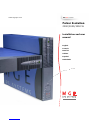 1
1
-
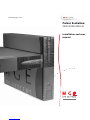 2
2
-
 3
3
-
 4
4
-
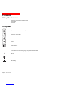 5
5
-
 6
6
-
 7
7
-
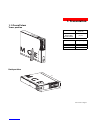 8
8
-
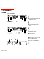 9
9
-
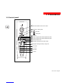 10
10
-
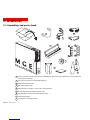 11
11
-
 12
12
-
 13
13
-
 14
14
-
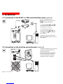 15
15
-
 16
16
-
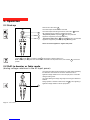 17
17
-
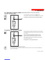 18
18
-
 19
19
-
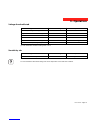 20
20
-
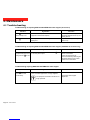 21
21
-
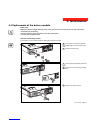 22
22
-
 23
23
-
 24
24
-
 25
25
-
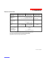 26
26
-
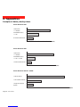 27
27
-
 28
28
-
 29
29
-
 30
30
-
 31
31
-
 32
32
-
 33
33
-
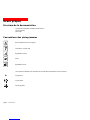 34
34
-
 35
35
-
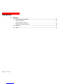 36
36
-
 37
37
-
 38
38
-
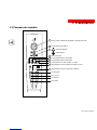 39
39
-
 40
40
-
 41
41
-
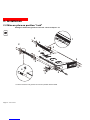 42
42
-
 43
43
-
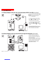 44
44
-
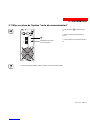 45
45
-
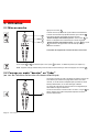 46
46
-
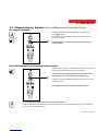 47
47
-
 48
48
-
 49
49
-
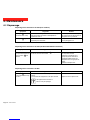 50
50
-
 51
51
-
 52
52
-
 53
53
-
 54
54
-
 55
55
-
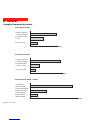 56
56
-
 57
57
-
 58
58
-
 59
59
-
 60
60
-
 61
61
-
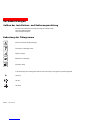 62
62
-
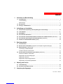 63
63
-
 64
64
-
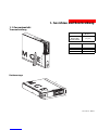 65
65
-
 66
66
-
 67
67
-
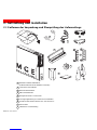 68
68
-
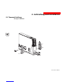 69
69
-
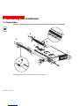 70
70
-
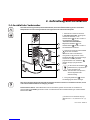 71
71
-
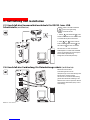 72
72
-
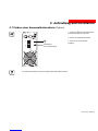 73
73
-
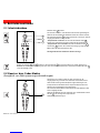 74
74
-
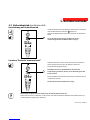 75
75
-
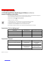 76
76
-
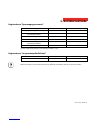 77
77
-
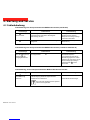 78
78
-
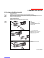 79
79
-
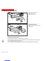 80
80
-
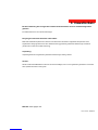 81
81
-
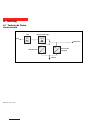 82
82
-
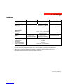 83
83
-
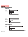 84
84
-
 85
85
-
 86
86
-
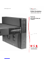 87
87
-
 88
88
-
 89
89
-
 90
90
-
 91
91
-
 92
92
-
 93
93
-
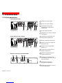 94
94
-
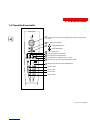 95
95
-
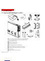 96
96
-
 97
97
-
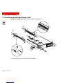 98
98
-
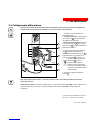 99
99
-
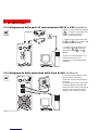 100
100
-
 101
101
-
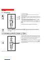 102
102
-
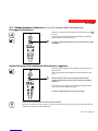 103
103
-
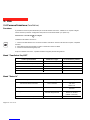 104
104
-
 105
105
-
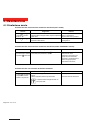 106
106
-
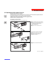 107
107
-
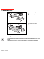 108
108
-
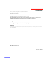 109
109
-
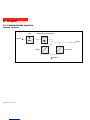 110
110
-
 111
111
-
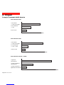 112
112
-
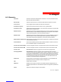 113
113
-
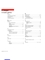 114
114
-
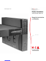 115
115
-
 116
116
-
 117
117
-
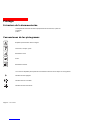 118
118
-
 119
119
-
 120
120
-
 121
121
-
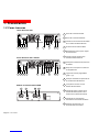 122
122
-
 123
123
-
 124
124
-
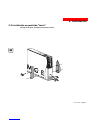 125
125
-
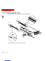 126
126
-
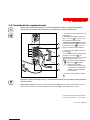 127
127
-
 128
128
-
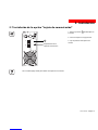 129
129
-
 130
130
-
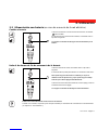 131
131
-
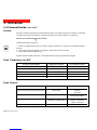 132
132
-
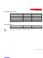 133
133
-
 134
134
-
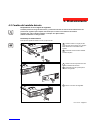 135
135
-
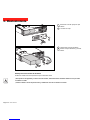 136
136
-
 137
137
-
 138
138
-
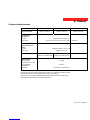 139
139
-
 140
140
-
 141
141
-
 142
142
-
 143
143
-
 144
144
-
 145
145
-
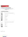 146
146
-
 147
147
-
 148
148
-
 149
149
-
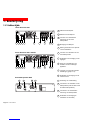 150
150
-
 151
151
-
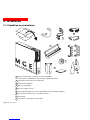 152
152
-
 153
153
-
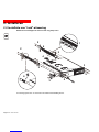 154
154
-
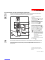 155
155
-
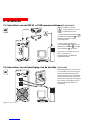 156
156
-
 157
157
-
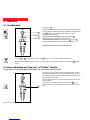 158
158
-
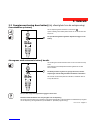 159
159
-
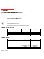 160
160
-
 161
161
-
 162
162
-
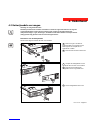 163
163
-
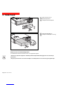 164
164
-
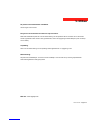 165
165
-
 166
166
-
 167
167
-
 168
168
-
 169
169
-
 170
170
-
 171
171
-
 172
172


