Adler 30 Operating Instructions Manual
- Categoría
- Máquinas de coser
- Tipo
- Operating Instructions Manual

I ·
~
-
,~
-
ADLER
30
Bedienungsanleitung
-------
Operating Instructions
-----
Instructions
de
service
-----
lnstrucciones
de
empleo
lstruzioni
per
l'uso

Allgemeines
1. Diese Gebrauchsanleitung aufmerksam durchlesen
und
die
Empfehlungen
beachten.
2.
Die
folgenden Bedienungspunkte gelten
fur
die
grundsiitzliche
Bedienung der
Adler
30.
Weicht
die Bedienung der Unterklassen
von
der
Grundausfuhrung
ab, siehe beigelegter Gebrauchsanleitungszusatz.
3.
Die
einzelnen Sprachen haben
wir
am
Blattrand
mit
einem
Regi-
ster gekennzeichnet.
D
fur
Deutsch
E
fur Englisch
F
fiir
Franzosisch
S
fiir
Spanisch
Klappen Sie
bitte
jetzt
die
am SchluB
befindliche
Bildtafel
nach
rechts heraus,
damit
Sie
Text
und
Bild
mit
einem
Blick
erfassen
konnen
.
4.
Um
die Lebensdauer der Maschine zu verlangern,
sollte
die
max.
Stichzahl
in
folgenden
Fallen
reduziert
werden
:
Wahrend der Einlaufzeit
Bei
starkem Material
Bei Oauerbelastung
Bei
groBer Stichlange
Bei schwierigen Arbeitsvorgangen
• Bedienungselemente Abb. 1
und
10
1 Fadenflihrungsloch
2 Fadenhebel
3 Einstellschraube
fur
Faden-
hebel
4 Skala
fur
Materialstarke
5
Garnrollenstift
6 Handrad-E
inrastknopf
7
Handrad
(sitzt
bei
Stop-
motor
fest
auf
Armwelle)
8
Spuler
9 schwenkbare
Stichplatte
10
Drehbarer
Obertransportfu
B
11
Stichsteller-Skala
12
Einstellschieber
fiir
Stichliinge
Auspacken
13
Fliigelgriff
(zum
Verandern
der
Nahrichtung)
14
Nahfu
B-Liifterhebel
(Masch .-Riickseite)
15
Fliigelschraube
fur
Stichst.·
E instel lschieber
16
Oberfadenspannung
1 7 F adenfiih rung
18
Fadenfiihrung
19
Fadenfiihrungsstift
21
Druckknopf
zum
Aus-
schwenken der
Stichplatte
22
Nahfu
B-Befestigu ngs-
schraube
1.
In
Gegenwart
des
Oberbringers die
Verpackung
auf
Beschadi-
gung
priifen.
2. Nahmaschine, Gestell
und
Zubehor
auf
Transportschaden
und
Vollstiindigkeit
priifen
.
3.
Bei Beschiidigung
sofort
in
Gegenwart des Oberbringers rekla-
mieren
.
Komplettieren
1. Gestellbezeichnung teststellen.
2. Entsprechend den
Abb.
11-13
Gestell
montieren.
Diese
Abbildungen
dienen als
Montageanleitung
wie
die
entspre·
chenden Gestelle
in
montiertem
Zustand
auszusehen haben.
3.
Niihmaschine aufsetzen.
4.
Antriebsriemen
auf
Nahmaschine-Antriebsscheibe
und
kleine
Gestell-Schwungscheibe
100,
Abb
.
11
und
12,
auflegen.
5.
Keilriemen
durch
Ausschwenken
des
Motors
entsprechend
spannen.
• Reinigen und Olen
1.
Di-uckknopf
21,
Abb
. 1,
niederdriicken,
Stichplatte
9 nach
hin·
ten
schv.,enken.
2.
Alie
Teile
mit
einem sauberen Lappen von
Rostschutzfett
und
evtl.
Schmutz
befreien.
3.
Durch
Pfeile
in
Abb.
3
und
4 gekennzeichneten Cltstellen
olen.
4. Unser
51
mit
folgenden
Richtdaten
verwenden:
Viskositiit
bei
40°
C,
cSt:
65;
E =
8,6
Viskositat
bei
50°
C,
cSt:
42;
E = 5,6
Bestellnummer
fur
1-Liter-Kanister
=
990
4 7
012
8.
Bestellnummer
fur
5-Liter-Kanister
=
990
47
012
9.
• Oberfaden einfadeln
1. Den von der
Garnrolle
kommenden
Oberfaden
fadeln
Sie
wie
die
Abb.
2 zeigt,
ein.
2. Beachten Sie bei
der
Einfiidelung
durch
die
Nadelstangen-
Bohrung
1, daB Sie das ca. 25
cm
lange Fadenende
in
den
dem
Normalzu-
behor
beiliegenden
Einfiideldraht
legen
und
den
Draht
von
oben
nach
unten
durch
die
Bohrung
fuhren. Dann
Oberfaden
festhal-
ten
,
Einfadeldraht
zuriickziehen
und
weiter
-
wie
in
Abb
. 2 ge-
zeigt
- vorgehen.
Nadel
und
Garn
1.
Fiir
Adler
30-10
= Nadel system
332
L
und
fur
Adler
30-50
und
30-70
= Nadelsystem
332
LLG
verwenden.
2.
Allgemeine
Regel
fur
die
Nadelstarke:
Klemmt
Faden
in
der
langen
Rille
= starkere Nadel verwenden.
Hat
Faden zuviel
Luft
in
der langen
Rille
= schwachere Nadel ver-
wenden.
3.
Oberfaden
auf
Materialstarke
abstimmen
und
linksgedrehten Fa-
den gebrauchen. Rechtsgedrehter
gibt
keinen
so
schonen
und
klaren
Stich.
4.
Unterfaden
sollte
schwiicher
oder
weicher
als
Oberfaden sein.
Nadel auswechseln
1. Nadelstange in
hochste
Stellung
bringen (Seitenhandrad nach
rechts
drehenl.
2. Schraube
33,
Abb
. 9, losen.
3. Nadel nach
unten
aus
Nadelstange ziehen.
4. Neue Nadel
mit
!anger Rille
nach
links bis
zum
Anschlag
ein-
setzen
und
Schraube
33
wieder
festdrehen.
R ichtiges
Stich
loch verwenden
Je nach Nadelstarke
konnen
Sie eines der beiden
Stichlocher
in
der
schwenkbaren
Stichplatte
verwenden.
1.
Fiir
stiirkere Nadeln = grolles
Stichloch
fiir
diinnere Nadeln = kleines
Stichloch.
2. Dabei
Oruckknopf
21,
Abb.
7,
herunterdriicken
und
Stichplatte
drehen, bis entsprechendes
Stichloch
unter
der Nadel ist.
Bitte
beach
ten,
daB
Stift
34
wieder ins
Loch
35
einrastet.
NahfuB auswechseln
1. Nadelstange
in
hochste
Stellung
bringen.
2.
NiihfuB-Liifterhebel
14,
Abb.
1 (Masch.-Riickseite), nach oben
stellen.
3. Schraube
22
losen
und
NiihfuB
abnehmen.
4. Neuen
Full
in
umgekehrter
Reihenfolge befestigen.
Schiffchen herausnehmen
1. Nadelstange
durch
Drehen am
Handrad
in
hochste
Stellung
brin-
gen.
(Nicht
bei Masch.
mit
Stopmotor.
Hier
bleibt
Nadel
immer
in
hochster
Stellung
stehen.)
2.
Druckknopf
21,
Abb
. 7,
herunterdriicken
und
gleichzeitig
Stich-
platte
9 nach
hinten
schwenken.
3.
Schiffchen
36
herausheben.
Unterfaden aufspulen
1. Riindelschraube
6,
Abb
. 5, nach
vorn
ziehen
und
drehen bis Stif1
autliegt
. Nahmaschine
ist
ausgeschaltet,
Handrad
liiuft
leer.
Bei Maschinen
mit
Stopmotor
laBt
sich
das
j-landrad
nicht
aus-
schalten. Das
Niihwerk
lauft
immer
mit.
2.
Unterfaden
von
der
Garnrolle
37
,
Abb.
5,
durch
die
Fadenfiih·
rung
38
fiidel
n.
3.
Zwischen
die
Scheiben
der
Spannung
39
fuhren.
4.
Um
die
Spule
40
wickeln.
5. Spule
auf
Spulerwelle
41
stecken.
6. Schraube
42
losen, nach
unten
schwenken
und
festdrehen (da-
durch
wird
Spulerrad
gegen
Handrad
gedriickt
und
lauft
mit).
7.
Mit
Griff
101
Hand
rad
drehen,
bis Spule
gefullt
ist
.
8. Schraube
42
losen, nach oben schwenken
und
festdrehen.
9.
Gefullte
Spule
abnehmen.
Spule einlegen, Unterfaden einfadeln
Kleines
Schiffchen:
1. Spule
43
so einlegen, daB sich
der
Faden
abwickelt,
wie
es
die
Abbildung
6
links
zeigt.
2. Faden
durch
Spulenschlitz
44
3.
in
den
Schlitz
45,
4.
unter
die
Spannungsfeder
46
und
5.
etwa
8
cm
durch
das
Loch
47
fiideln.
GroBes
Schiffchen:
1. Spule
48
so
einlegen, daB sich der Faden
abwickelt,
wie
es
die
Abbildung
6 rechts zeigt.
2. Faden
durch
das
Loch
49,
3.
unter
die
Spannungsfeder
50,
4.
durch
das
Loch
51
und
5.
etwa
8
cm
durch
die
Bohrung
52
fadeln.
6.
Spulenbremsfeder
53
Uber Spule schieben (soil einen
leichten
Druck
darauf
ausiiben).
From the Library of Superior Sewing Machine & Supply LLC

• Schiffchen einlegen
1.
Schiffchen
36,
Abb.
7,
in
Schiffchenkorb
einlegen
und
heraushiin-
gendes Fadenende nach
hinten
in
die
Aussparung 54 legen.
2.
Druckknopf
21
herunterdrucken
und
Stichplatte
9
wieder
ein-
schwenken,
bis
Stift
34
einrastet
(Druckknopf
21
dabei loslassen).
• Stichliinge einstellen
GroBere Stichliinge:
1. Flugelschraube 15,
Abb.
9,-losen.
2. Einstellschieber 12 nach
unten
stellen.
3.
Fliigelschraube
15
festdrehen.
Kleinere Stichliinge:
1. Fliigelschraube 15,
Abb.
9,
losen.
2. Einstellschieber 12 nach oben stellen.
3.
Fliigelschraube
15
festdrehen.
Das
Einstellen
des
Ruckwiirtsstiches
wird
hier
durch
die
allseitige
Transportrichtung
ersetzt,
die
durch
Drehen
des
Flugelgriffes
13
bestimmt
wird.
• NiihfuBdruck einstellen
Starker Druck:
1.
Gegenmutter
56,
Abb.
4,
losen.
2. Schraube 57 rechtsherum drehen.
3.
Gegenmutter
festdrehen.
Schwacher Druck:
1.
Gegenmutter
56 liisen.
2. Schraube 57
linksherum
drehen.
3.
Gegenmutter
festdrehen.
• NiihfuBhub einstellen
Niihfullhub
entsprechend
der
Starke
des
zu verniihenden Materials
einstel len.
1. Schraube
102,
Abb.
4,
liisen.
2.
Hubstellkloben
69
auf
Blattfeder
59
verschieben. Je
weiter
der
Kloben
nach
links
geschoben
wird,
desto
hiiher
der
Niihfullhub.
3.
Schraube
102
festdrehen.
• Fadenhebel einstellen (Fadengabe)
Der
Fadenhebel
bzw.
die
Fadengabe ist
vom
Herstellerwerk
fur
nor-
males
Niihmaterial
eingestellt.
Bei
Verarbeitung
von
extrem
starken
oder
schwachem Niihrnaterial
mull
der
Fadenhebel
darauf
eingestellt werden.
1. Schraube
3,
Abb.
1,
liisen
und
Zeiger
auf
Skala 4 entsprechend
einstellen:
dunn
fur
2
mm
starkes Nahmaterial
mittel
=
fur
5
mm
starkes Nahmaterial
dick
=
fur
8
mm
starkes Nahmaterial
Jeder
Teilstrich
der
Skala
entspricht
einer
Materialstarke
von
1
mm.
2.
Schraube
3 festdrehen.
3.
Achten
Sie
bitte
darauf,
dall
beim
Einstellen der Fadengabe
der
Faden
nicht
gespannt
ist,
wenn die Nadelspitze
in
das
Nahmate-
rial
einsticht.
•
Zum
Niihen vorbereiten und niihen
Fullbetriebsmaschine:
1.
Unterfaden
heraufholen.
Oberfaden
dabei
festhalten
und
Handrad 7,
Abb.
1,
rechtsherum
drehen
(Einrastknopf
6
mull
eingerastet sein,
damit
das
Nahwerk
beim
Drehen des Handrades
mitliiuft).
2.
Nahfull
10
durch
Lufterhebel
14
hochstellen.
3.
Beide Faden nach
hinten
unter
den
Nahfull
legen.
4.
Nahmaterial
unter
Nahfull
legen
und
Nahfull
durch
Lufterhebel
14
sen
ken.
5.
Mit
Handrad Niihmaschine
in
Bewegung setzen,
gleichzeitig
beide
Fiille
auf
Fulltritt
setzen
und
mit
rhythmischen
Tretbewegungen
Nahmaschine
in
Gang setzen. Maschine
naht.
Sind
diese
Tretbe-
wegungen
nicht
gelaufig,
bitten
wir
zweckmalligerweise bei aus-
geschaltetem
Nahwerk
zu uben.
6.
Nahmaterial
nie schieben oder ziehen.
7.
Anderung
der
Niihrichtung
durch
Drehen des doppelseitigen
Flii-
gelgriffes
13.
Die
Anderung
nur
vornehmen,
wenn
der
Transport-
full
nicht
auf
das Nahmaterial
driickt
(Beschadigung der Nahma-
terial-Oberflache).
Mit
der
Schraube
61
kann der
Fliigelgriff
fest-
gestellt
werden
(konstante
Nahrichtung).
8. Maschine ohne
Stoff
nur
dann laufen !assen,
wenn
Nahfull
ange-
hoben
ist.
FuB- und Motorbetriebsmaschine:
1.
Spannung
(Volt)
auf
dem
Stromzahler
mull
mit
den Angaben
auf
dem
Motorschild
ubereinstimmen.
2.
Zufiihrungsstecker
mit
dem
Netz
verbinden.
3.
Schwungradzugstange
durch
Liisen der Schraube aushangen. (Soll
mit
Fullbetrieb
gearbeitet werden,
mull
die
Motorzugstange
aus-
gehiingt
werden.)
4.
Unterfaden
heraufholen
(Oberfaden dabei festhalten
und
Hand-
rad
einmal
rechtsherum drehen).
5.
Nahfull
durch
Lufterhebel
14,
Abb.
1, hochstellen.
6.
Beide Faden nach
hinten
unter
Nahfull
legen.
7.
Nahmaterial
unter
Nahfull
legen
und
Niihfull
durch
Lufterhebel
14
senken.
8.
Fulltritt
herunterdriicken.
Maschine
niiht.
Je
weiter
der
Fulltritt
durchgedruckt
wird,
desto schneller
naht
die Maschine.
Nahmaterial
nie
schieben
oder
ziehen.
9.
Anderung
der
Nahrichtung
durch
Drehen
des
doppelseitigen
Fliigelgriffes
13.
Die
Anderung
nur
vornehmen,
wenn
der
Trans-
portfu
ll
nicht
auf
das
Niihmaterial
driickt
( Beschiidigu
ng
der
Nahmaterial-Oberflache).
Mit
der Schraube
61,
Abb.
1,
kann
der
Fliigelgriff
festgestellt
werden
(konstarite
Niihrichtung).
10. Maschine
ohne
Stoff
nur
dann
laufen
I assen, wenn
Nahfull
an-
gehoben ist.
11. Nach
dem
Niihen
Motor
abschalten.
I Fad.enspannung iindern
1.
Naht
nach
einer
kurzen
Strecke
priifen.
2.
Abbi
I dung 8
(Stichtyp
301)
oben Verschlingung
der
Faden
richtig,
mitte
Oberfadenspannung zu schwach,
oder
Unterfaden-
spannung zu
stark,
unten
Oberfadenspannung zu
stark,
oder
Unterfadenspan-
nung zu schwach.
3.
Oberfadenspannung
mit
Spannungsmutter
103,
Abb.
1, einstellen
schwiichere Spannung =
Mutter
103
nach rechts drehen,
stiirkere Spannung =
Mutter
103
nach
links
drehen.
4.
Unterfadenspannung
moglichst
nicht
verandern. Falls
doch
erfor-
derlich,
mit
Schraube
62,
Abb.
6,
einstellen:
stiirkere
Spannung
= Schraube
62
nach rechts drehen,
schwiichere Spannung
= Schraube
62
nach
links
drehen.
I Reinigen und Olen
1. Nach liingerer Betriebsdauer
oder
liingerem
Stillstand
mull
die
Niihmaschine
gereinigt
werden (siehe auch vorstehenden
Punkt
,.Reinigen
und
Olen").
2.
Var
dem
Oien etwas
Petroleum
an
die
erwiihnten
Stell en geben.
3. Nahmaschine
mit
angehobenem FuB
kurz
laufen !assen.
4.
Schmutz
abputzen
und
Maschine olen.
Anschiebetisch verwenden
Um
auch
,.Flacharbeiten"
auf
der
Adler
30
ausfiihren zu
konnen,
kann
auf
Wunsch ein Anschiebetisch
geliefert
werden.
Dieser Holzanschiebetisch
wird
vorn
iiber
den
Unterarm
geschoben
und
in
die
am
Unterarm
angebrachten Ansatze
eingehakt.
Tischstut·
ze
herausschwenken
und
in
das
Loch
der
Gestellplatte
einsetzen.
• Bandeinfasser verwenden.
1.
Normale
Stichplatte
abschrauben.
2.
Stichplatte
63,
Abb.
10,
mit
Bandfiihrungsstiften
aufschrauben.
3.
Bandfuhrungsschnecke
64
mit
Schraube
65
so
befestigen, daB
der
Stichplattenansatz
66
in
der
Nute
der Bef.-Platte liegt.
4.
Vorderkante
der
Schnecke
64
mit
Stichlochkante
67
abschnei-
den lassen.
5.
Normalen
Nahfull
abschrauben.
6.
SpezialnahfuB
so
anschrauben,
dall
das
Unterteil
unter
den
Stichplattenzapfen
und
der
Zapfen
zwischen den Fiihrungs-
stiften
liegt.
7. Bandfiihrungsscheiben
in
die
hintere
Bohrung
im
Zylinder
an-
schrauben.
8.
Bandrolle
zwischen
die
Scheiben legen
und
Spannmutter
so
an-
ziehen,
dall
das Band
leicht
gespannt ist.
9. Band
(Anfang
etwas anschriigen)
durch
die
Stifte
68,
durch
die
Schnecke
64
und
zwischen
Nahfullober-
und
Unterteil
fiihren.
10.
Das
einzufassende
Nahmaterial
zwischen Schneckenansatze
und
damit
zwischen das
Einfallband
schieben, wobei
die
lnnenkante
der Schnecke als Anschlag
fur
das
gleichmallige
Einlaufen
des
Nahgutes
dient.
Die Schnecke legt
das
Einfallband
beiderseits
gleichmiillig
um
das
Niihmaterial.
11.
Bandbreite
muB
zur
Schnecke passen,
d.h.
es
darf
nicht
breiter
sein als
es
die
Schnecke
zuliillt.
Es
ist
also
fur
jede
Bandbreite
eine andere Schnecke
erforderl
ich.
• Allgemeiner Hinweis
Sollten
noch
irgendwelche
Unklarheiten
bestehen,
bitte
Vertreter
oder
Fachberater
anfordern.
Bei Ruckfragen
im
Werk
bitte
angeben:
1.
Lieferdatum
2. Klassenbezeichnung
3.
Oberteilnummer
From the Library of Superior Sewing Machine & Supply LLC

General
1. Please read
the
present
instructions carefully
and
observe
the
re-
commendations.
2.
The
following
text
applies
only
to
the
basic
operation
of
the
Adler
30.
If
operation
of
the
sub-classes differs
from
that
of
the
basic design, please see
the
attached
supplementary
instructions.
3.
The
different
languages have
been
marked
on
the
sheet
margin
by
the
respective letters:
D German
E English
F
French
S Spanish
Please
unfold
the
table
of
illustrations
at
the
end
to
the
right
so
that
you
can
see simultaneously
the
text
and
the
illustrations.
4.
In
order
to
extend
the
life
of
the
machine
the
maximum
sewing
speed
should
be
reduced in following cases:
During
the
running-in period
In
the
case
of
thick
material
When in
continuous
use
When using long stitches
When difficult
operations
are
involved
Operating elements
1
Thread
guide hole
2
Thread
take-up lever
3 Adjusting screw
for
take-up
lever
4 Scale
for
material thickness
5
Thread
reel pin
6 Handwheel locking
button
7 Handwheel (fixed
on
the
right
on
the
arm
shaft
when using a
stop
motor)
8 Bibbin winder
9 Hinged
throat
plate
10
Rotary
top
feed
foot
11
Stitch
regulator scale
12
Slight
for
adjusting
the
stitch
length
Unpacking
13 Wing handle
for
changing
the
direction
of
sewing
14 Sewing
foot
lifter
lever
15 Wing screw
for
the
adjust
·
ment
slide
of
the
stitch
regulator
16 Needle
threat
tension
17
Thread
guide
18
Thread
guide
19
Thread
guide
pin
21
Pushbutton
for
swinging
out
the
throat
plate
22
Sewing
foot
fastening
screw
1. Check
the
packing
for
damage in
the
presence
of
the
carrier
.
2. Check sewing
machine
,
stand
and
accessories
for
any
possible
transport
damage.
3.
Immed
i
ately
notify
any
damage in
the
presence
of
the
carrier
Assembly
1. Check
the
stand
designation.
2. Fasten
the
sew
ing machine
to
the
stand
by
screws
according
to
figs.
11-13
. These illustrations serve as
mounting
instruc
-
tions
and
show
how
the
respective assembled
stands
should
look like.
3. Place
the
driving
belt
on
the
sewing machine driving
pulley
and
place
the
small
stand
flywheel
100
, figs.
11
and
12
.
4.
Tension
the
V-belt as required as swinging
out
the
motor.
Cleaning and oiling
1. Depress
the
push
button
21,
fig. 1 . Swing
the
throat
plate
9
to
the rear.
2. Using a
clean
cloth
, remove anti-corrosion grease
and
dirt
from
all
components
.
3.
Oil all lubricating
points
marked
by
arrows in figs. 3
and
4.
4.
Use
our
oil with following
propert
ies:
Viscosity
at
40°
C
cSt
:
65;
E = 8.6
Viscosity
at
50°
C
cSt:
42;
E = 5.6
Ref. No.
990
47
012
8
for
1 litre
container
Ref. No.
990
47
012
9
for
5 litre
container
.
Threading the needle thread
1. Pass
the
needle
thread
from
the
reel as
shown
in fig. 2.
2. When passing
the
thread
through
the
needle
bar
hole 1 place
the
about
25
cm
long
thread
end
in
the
threading wire sup-
plied
with
the
standard
accessories
and
pass
the
wire
through
the
hole
downwards.
Then
hold
fast
the
needle
thread
, pull
back
the
threading
wire
and
proceed
as shown in fig. 2.
Needle and thread
1. Use
tor
Adler
30
-
10
the
needle
system
332
Land
for
Adler
30-50
and
30-70
the
needle system
332
LLG.
2. General rule
for
needle size:
If
the
thread
jams in
the
Jong groove use a thic)ser needle.
If
the
thread
has
too
much clearance in
the
long groove use
a
thinner
needle.
3. Match
needle
thread
to
mater
ial thickness
and
use left-torsion
threads. Right-torsion
threads
w
il
l
not
produce
so nice
stitches
4 .
The
bobbin
thread
should
be
thinner
or
softer
than
the
needle
thread.
Replacing the needle
1.
Conduct
the
needle
bar
to
its
topmost
position.
(Turn
the
side
handwheel
clockwise.)
2. Loosen
the
screw
33,
fig. 9.
3.
Remove
the
needle
from
the
needle bar
by
pulling it
downwards
.
4.
Insert
new
needle
with
the
groove facing
to
the left
and
retigh-
ten the
screw
33.
Use correct needle hole
According
to
the
needle
thickness ei
ther
of
the
two
needle holes
in
the
pivot-mounted
throat
plate
can
be
used.
1.
For
thick
needles = large
stitch
hole
For
thin
needles = small
stitch
hole
2.
Depress
the
pushbutton
21, fig.
7,
and
turn
the
throat
pl
ate
until
the
appropriate
needle
ho
le is
underneath
the
needle.
Ensure
that
the
pin
34
snaps again in
the
hole
35
.
Replacing the sewing
foot
1.
Conduct
the
needle
bar
to
its
topmost
point.
2. Move
the
sewing
foot
lifting lever
14,
fig.
1,
(on
the
backside
of
the
machine)
to
its
upper
position.
3.
Loosen
the
screw
22
and
remove
the
sew
ing
foot.
4.
Secure
new
foot
in inverse order.
Removing
the
shuttle
1.
Move
the
needle
bar
to
its
topmost
point
by
turning
the
handwheel
(not
in machines
with
stop
motor.
Here
the
needle
stops
always
in its
upper
position).
2. Depress
the
pushbutton
21, fig. 7
and,
at
the
same
time,
swing
the
throat
plate
9
to
the
l
eft.
3. Remove
the
shuttle
36
.
Winding
the
bobbin thread
1. Pull
the
knurled
screw
6,
fig.
5,
forwards
and
turn
it
unt
il
the
pin rests,
the
machine
stops
and
the
handwhee
l runs idle.
In machines
with
stopmotor
the
handwheel
cannot
be
dis-
connected
.
The
sewing
mechan
i
sm
continues
operating.
2. Pass
the
bobbin
thread
from
the
reel
37,
fig.
5,
th
r
oug
h
the
thread
guide
38
,
3. between
the
disks
of
the
tension
39
.
4 . Wind
the
thread
around
the
bobbin
40.
5. Slip
the
bobbin
on
the
bobbin
winder
shaft
41.
6. Loosen
the
screw
42,
swing
it
down
and
tighten
(in
th
is way
the
winder wheel will
be
pressed against
the
handwhee
l
and
will follow its
rotation).
7. By means
of
the
handle
101
turn
the
handwheel until t
he
bobbin
is
filled.
8. Loosen
the
screw
42,
swing
it
upwards
and
tighten.
9. Remove
the
filled
bobbin
.
Inserting
the
bobbin,
threading
the
bobbin thread
Small
shuttle
1.
Insert
the
bobbin
43
so
that
the
thread
is
unwound
as
shown
in fig. 6,
on
the
left.
2. Pass
the
thread
through
the
bobbin
slit
44
3.
into
the
slit
45,
4.
underneath
the
tensioning spring
46
and
5.
approx
. 8
ems
through
the
hole
47
.
Large
shuttle
1. Insert
the
bobbin
48
so
that
the
thread
is
unwound
as
shown
in fig.
6,
on
the
right.
2. Pass
the
thread
through
the
hole
49
,
3.
underneath
the
tens
i
oning
spring 50,
4.
through
the
hole
51
and
5.
approx
. 8
ems
through
the
hole
52.
6.
Slip
bobbin
brake
sp
ring 53 over
the
bobbin (so
that
it
exerts
a slight pressure
on
the
latter).
Inserting the shuttle
1. Place
the
shuttle
36,
fig. 7,
into
its cage
and
place
the
protrud
,
ing
thread
end
to
the
rear
into
the
recess
54.
2. Depress
the
push
button
21
and
swing back
the
throat
plate
9
until
the
pin
34
engages (release
at
the
same
time
the
push
button
21
).
From the Library of Superior Sewing Machine & Supply LLC

Adjusting
the
stitch length
Increased stitch length:
1. Loosen
the
wing screw
15,
fig. 9.
2. Lower
the
slide ) 2.
3.
Tighten
the
wing screw
15.
Reduced stitch length:
1. Loosen
the
wing screw
15,
fig. 9.
2.
Lift
the
slide 12.
3.
Tighten
the
wing screw 15.
Adjustment
of
the
reverse
stitch
is,
in
this case, replaced
by
the
universal feed device which
is
governed by rotating
the
wing
handle
13.
Adjusting
the
sewing
foot
pressure
High pressure:
1. Loosen the
counter
nut
56, fig. 4.
2.
Turn
the
screw 57 clockwise.
3.
Tighten
the
counter
nut.
Low pressure:
1.
Loosen
the
counter
nut
56.
2.
Turn
the
screw 57 counter-clockwise
3.
Tighten
the
counter-nut.
a Adjusting the sewing
foot
lift
Adjust
the
sewing
foot
lift according
to
the
thickness
of
the
material
to
be
sewn.
1. Loosen
the
screw
102,
fig.
4.
2. Displace
the
lift adjusting clamp
69
on
the
leaf spring 59.
The
further
the
clamp
is
moved
to
the
left,
the
higher
is
the
presser
foot
I ift.
3.
Tighten
the
screw 102.
Adjusting the thread take-up lever
The
thread
take-up lever has been adjusted in
the
factory
for stan-
d&rd sewing material. When processing
extremely
thick
or
thin
material
the
thread
take-up lever must be adjusted accordingly.
1. Loosen
the
screw
3,
fig. 1, and set
the
pointer
on
the
scale 4
accordingly.
thin
=
for
2
mm
thick
material
medium
= for 5
mm
thick
material
thick
for 8
mm
thick
material.
Each division on
the
scale corresponds
to
a material thickness
of
1
mm.
2.
Tighten
the screw
3.
3.
Ensure
that,
when adjusting
the
take-up lever,
the
thread
is
not
tensioned
when
the
needle
point
enters
the
material.
Preparation for sewing and sewing
Foot-operated
machine:
1. Pull
up
the bobbin
thread.
While doing this,
hold
fast
the
needle
thread
and
rotate
the
handwheef
7,
fig.
1,
clockwise (the locking
button
6
must
have
snapped,
so
that
the
sewing mechanism follows
the
rotation
of
the
handwheel).
2. Lift
the
sewing
foot
10
by
the
lever 14.
3.
Place
both
threads
to
the
rear blow
the
sewing
foot.
4.
Place
the
material
underneath
the
sewing
foot
and
lower
the
sewing
foot
by
the
lifting lever 14.
5.
Put
the
sewing machine
into
motion
by
the
handwheel
and,
at
the
same
time,
place
both
feet on
the
pedal
and
start
sewing
by
operating
the
pedal in a regular manner.
If
you
are
not
used
to
operate
the
pedal, we recommend
that
you
practise
for a while with
the
sewing mechanism
cut
out.
6.
Never push
or
pull
the
material
to
be sewn.
7. Changing
the
direction
of
sewing by rotating
the
double-sided
wing_handle
13.
This
should
be
done
only
while
the
feeding
foot
does
not
press
onto
the
material (so as
not
to
damage
the
surface
of
the
sew-
ing material).
The
wing handle can be locked in position
by
the
screw
61 (constant direction of sewing).
8.
Operate
the
machine
without
fabric
only
if
the
sewing
foot
is
lifted.
Foot and motor-operated machine:
1.
The
voltage
on
the
current
meter
should
coincide with
the
de-
tails
on
the
motor
plate.
2. Plug
supply
llne Into mains.
3.
Hang
out
the
flywheel
tie
rod by loosening
the
screw.
(For
pedal
operation
the
motor
tie rod must be disengaged.)
4.
Pull
up
the
bobbin
thread
(hold fast
the
needle
thread
and
turn
the
handwheel
once
clockwise).
5.
Lift
the
sewing
foot
10
by
the
lever
14,
fig. 1.
6.
Place
both
threads
towards
the
rear
underneath
the
sewing
foot.
7. Place material
under
the
sewing
foot
and
lower
the
latter
by
the
lever 14.
8.
Lower
the
pedal.
The
machine will
start
sewing.
The
further
the
pedal
is
lowered,
the
fast
the
machine will sew.
Never push
or
pull
the
material
to
be sewn.
9. Changing
the
direction of sewing by rotating
the
double-sided
wing handle
13.
This should be
done
only
while
the
feeding
foot
does
not
press
onto
the
material (so as
not
to
damage
the
surface of
the
sew-
ing material).
The
wing handle
can
be locked
in
position by
the
screw
61,
fig. 1
(constant
direction of sewing).
10. Allow
the
machine
to
run
without
any
material only with
the
sewing
foot
lifter.
11.
After
sewing, switch
off
the
motor.
Adjusting the thread tension
1. Check
the
seam
after
having sewn a
short
distance.
2.
Fig. 8 (stitch
type)
above
correct
interlocking of threads
centre
needle
thread
tension insufficient
or
bobbin
thread
tension
excessive
below needle
thread
tension excessive
or
bobbin
thread
tension
insufficient
3.
Adjust
the
needle
thread
tension by
the
nut
103,
fig.
4:
For
reducing
the
tension
=
turn
the
nut
103
clockwise.
For
increasing
the
tension=
turn
the
nut
103
counter-clock-
wise.
4.
If
possible,
do
not
change
the
bobbin
thread
tension.
Should
this, however,
become
necessary, regulate
it
by
the
screw
62,
fig.
6.
For
increasing
the
tension=
turn
the
screw
62
clockwise.
For
reducing
the
tension=
turn
the
screw
62
counter-clockwise.
Cleaning and oiling
1.
After
a longer
period
of
use
or
standstill
the
sewing machine
must
be cleaned (see also "cleaning
and
oiling"
above).
2. Before oiling, apply a small
amount
of
paraffin
to
the
poinds
indicated.
3.
Operate
the
machine for a
short
while with
the
foot
lifted.
4.
Wipe
off
any
dirt
and
oil
the
machine.
Use
of
fit-on table
In
order
to
be able
to
carry
out
"flat"
work
on
the
Adler
30,
a
fit-on table can
be supplied. This
wooden
table
is
fitted
over
the
lower arm in
front
and
hooked
into
the
lugs provided for
the
purpose
on
the
lower arm. Swing
out
the
table
support
and
in-
sert
into
the
hole
the
stand
plate.
Use
of
the tape binder
1. Unscrew
the
normal
throat
plate.
2. Screw-on
the
throat
plate
63,
fig.
10,
which
is
provided with
tape
guide pins.
3.
Secure
the
tape
guide worm
64
by
the
screw
65
in such a
manner
that
the
throat
plate lug
66
locates
in
the
groove of
the
fastening
pl
ate.
4.
The
front
edge of
the
worm 64
should
be flush with
the
edge
67
of
the
needle hole.
5. Unscrew
the
standard
sewing
foot.
6.
Screw-on
the
special sewing
foot
in such a
manner
that
the
lower
part
situates itself
under
the
throat
plate
trunnion
and
that
the
trunnion
locates itself between
the
guiding pins.
8.
Place
the
tape
reel between
the
disks
and
tighten
the
tension-
ing
nut
so
that
the
tape
is
slightly tensioned.
9. Pass
the
tape
(slightly
taper
the
leading edge)
through
the
pins
68,
through
the
worm
64
and
between
the
upper
and
lower section
of
the
sewing
foot.
10.
Push
the
material
to
be
bound
between
the
worm shoulders
and
thus
between
the
binding
tape,
the
inner edge
of
the
worm
serving as a
stop
to
ensure
an
even infeed of
the
material.
11.
The
tape
width
should
be
adapted
to
the
worm, i.e.
it
must
not
be wider
than
the
worm permits. It is,
therefore,
necessa-
ry
to
use a
different
worm
for
each
tape
width.
General indications
Should
you
have
any
queries, please
demand
the
visit of an agent
or
of
a consulting engineer.
If
your
questions are
directed
to
the
factory,
please specify:
1 . The
date
of del Ivery
2.
The
class designation
3.
The
machine head
number
From the Library of Superior Sewing Machine & Supply LLC

Generalites
1.
II
vaut la peine
de
lire
attentivement
ce
mode
d'emploi
et
de
suivre
les
conseils.
2. Le
texte
suivant
n'est
valable que
pour
l'Adler
30
standard
.
Se
referer aux notices complementaires
pour
les sous-classes
se differant
de
la
construction
de base.
3. Les differentes langues
sont
indiquees par les lettres respec-
tives
au
bord
de
I a page.
D allemand
E anglais
F
franc;;ais
S espagnol
Ouvrez
maintenant
la table des illustrations,
se
trouvant
a la
fin, vers la
droite
pour
avoir sous les
yeux
le
texte
et
les
illustrations.
4.
La longevite
de
la machine sera prolongee
si
la vitesse
de
couture
est
reduite dans
les
cas suivants:
Pendant
le rodage
Matieres
epaisses
Service
continu
Longueur
de
point
extreme
Operations de
couture
difficiles
a Elements de commande, figs. 1
et
10
1
Trou
guide-fil
2
Tendeur
de
fil
3 Vis de reglage
pour
le
tendeur
de
fil
4 Echelle
pour
la grosseur
de
matiere
5 Chevllle
porte-bobine
6 Bouton
pour
le verrouillage
du
volant
7
Volant
(en cas
du
moteur
stop
se
trouve fixe a
droite
sur
l'arbre
du
bras)
8 Devidoir
de
canettes
9 Plaque a aiguille pivotable
10 Pied
entrafneur
pivotable
11
Echelle regle..points
12 Giissiere
pour
le
reglage
de
la
longueur de points
• Deballage
13 Poignee ailee (pour modi-
fier le sens de
couture)
14 Levier elevateur
du
pied
de
couture
(dos)
15 Vis ailee
pour
la glissiere
regle-points
16 Tension
du
fil
d'aiguille
17 Guide-fil
18 Guide-fil
19
Cheville guide-fil
21
Bouton poussoir
pour
le
pivotement
de
la
plaque
a aiguiHe
22 Vis de fixation
du
pied
de
couture
1. Deballer la machine en presence
du
livreur
et
s'assurer
que
l'emballage
n'est
pas endommage.
2. S'assurer
que
ni
la
machine,
ni
la table, ni les accessoires
n'ont
ete
endommages
pendant
le
transport.
3.
Signaler
immediatement
au livreur les dommages eventuels.
• Completement
1.
Verifier la designation
du
biiti.
2. Visser la machine a
coudre
sur le biiti prepan! selon les figs .
11
a 13. Ces illustrations servant des instructions
demon-
tage
et
montrent
les differents biitis
en
etat
monte.
3.
Placer
la
courroie
de
commande
sur la poulie
de
commande
de
la
machine a
coudre
ainsi
que
la
petite
poulie
du
biiti
100,
figs.
11
et
12.
4.
Tendre
la
courroie
trapezoidale par le
pivotement
du
mo·
teur
.
Nettoyer
et
huiler
1.
Appuyer
sur
le
bouton
21,
fig. 1. Pivoter
la
plaque a aiguille
9 vers l'arriere.
2. A l'aide d
'un
drap
propre,
del iberer
toutes
les
pieces
de
la
graisse anti-rouille
et
eventuellement de
la
poussiere.
3.
Huiler
tousles
endroits
marques par
und
fleche dans les
figs.
3
et
4.
4.
Utiliser
ace
but
notre
huile avec les caracteristiques
appro·
i<imatives suivantes:
Viscosite a
40°
C,
cSt:
65;
E
8,6
Viscosite a
50°
C,
cSt:
42;
E
5,6
No
. de ref.
pour
un bidon
de
1 litre =
990
47
012
8
No. de
ref.
pour
un bidon
de
5
litres=
990
47
012
9.
Enfilage du
fil
d'aiguille
1. Passer
le
fil
en provenance
de
la bobine selon
la
fig. 2.
2. En passant
le
fil
par le trou 1
de
la barre a aiguille placer
le
bout
du
fil
de
25
ems environ dans
le
fil
de fer enfileur livre
avec les accessoires standard
et
passer
le
fil
de
fer
d'en
haut
vers
le
bas par
le
trou.
Mantenir ensuite le fil d'aiguille, retirer le fil
de
fer
et
pou-
suivre l'enfilage selon
la
fig. 2.
Aiguille
et
fil
1. Utiliser
pour
Adler
30-10
le
systeme d'aiguille
332
Let
pour
Adler
30-60
et
30-70
le
systeme d'aiguille
332
LLG.
2. Ragle gerierale
pour
la grosseur d'aiguille:
Utiliser
une
aiguille plus forte
si
le
fil
se coince dans la longue
rainure
de
l'aiguille.
Utiliser
une
aiguille
mains
forte
si
le
fil
a
trop
de
place dans la
longue rainure de l'aiguille.
3.
Adapter
le
fil
d'aiguille a lepaisseur de
la
matiere a
coudre,
et
utiliser les fils vec torsion a gauche.
Les
fils avec torsion a
droite
ne
produiront
pas un beau
point.
4.
Le
fil
de
canette
doit
t!tre plus mince ou plus sou pie
que
le
fil
d'aiguille.
Remplacement de l'aiguille
1.
Amener
la
barre a aiguille dans sa position la plus
haute
(tour·
ner
le vol
ant
a main lateral vars la
droite).
2. Desserrer la vis
33,
fig.
9.
3. Enlever l'aiguille
de
la barre a aiguille en
la
tirant
vers
le
bas.
4.
lntroduire
la nouvelle aiguille jusqu'a la butee
et
fixer par
la
vis
33.
La longue rainure de l'aiguille
doit
etre
orientee vers
la gauche. Resserrer
la
vis
33.
Utiliser
le
trou d'aiguille correct
Selon
la
grosseur d'aiguille vous pouvez utiliser un des deux trous
d'aiguille dans la plaque
a aiguille pivotante.
1. Pour des grosses aiguilles le grand
trou
et
pour
des aiguilles
minces le
petit
trou
.
2.
Appuyer
sur
le
bouton
21,
fig. 7,
et
tourner
la plaque a aiguille
jusqu'a
ce
que
le
trou
approprie
se
trouve en-dessous de I 'ai-
guille. S'assurer
que
la cheville
34
s'engage bien dans le
trou
35.
Remplacement du pied de couture
1. Amener la barre a aiguille dans sa position la plus
haute.
2. Mettre le levier elevateur
du
pied
de
couture
14, fig. 1, en
position
haute
..
3. Desserrer la
vis
22
et
enlever le pied de
couture.
4 . Fixer le nouveau pied dans
l'ordre
inverse.
Enlever
la
navette
1. Amener la barre a aiguille dans sa position
la
plus
haute
en tour-
nant
le
volant. (Pas dans les machines avec
moteur
Stop.
lei
l'aiguille
s'arrete
toujours
a son
point
culminant.)
2.
Appuyer
sur
le
bouton
21,
fig. 7,
et
pivoter en meme
temps
la plaque a aiguille 9 vers I 'arriere.
3. Enlever la navette
36.
Bobinage du
fil
de canette
1. Tirer
la
vis
moletee 6, fig. 5, en avant
et
la
tourner
jusqu'a
ce
que
la goupille
s'appuie,
la machine
s'arrete
et
le
volant marche
en
vide.
Dans les machines avec
le
moteur
stop
ii
est
impossible de de-
brayer
le
volant
.
Le
mecanisme
de
couture
suit
le
mouvement
du
volant
.
2. Passer le
fil
de
canette
en provenance
de
la
bobine
37,
fig. 5,
par
le guide-fil
38,
3.
entre
les disques
de
tension
39
et
4.
enrouler
le
fil
auteur
de la
canette
40.
5. Glisser la
canette
sur l'arbre
du
devidoir
41,
6. Desserrer la vis
42,
la
baisser
et
resserrer (ainsi la roue
du
devi-
doir
sera pressee
centre
le vol
ant
a main
et
suivra sa
rotation).
7. Par la poignee 101
tourner
le
volant
jusqu'a
ce
que
la
canette
soit
remplie.
8.
Desserrer la vis, la pivoter vers
le
haut
et
resserrer.
9.
Enlever la
canette
remplie.
Placement de
la
canette, enfilage
du
fil
de canette
Petite navette:
1. Placer
la
canette
43
de
sorte
que
le
fil
se deroule selon la fig.
6,
a gauche.
2. Passer le
fil par I.a
fente
44
3. dans la
fente
45,
4. sous
le
ressort de tension
46
et
5. environ 8 ems par
le
trou
4 7.
Grosse navette:
1. Placer la
canette
48
de
sorta
que
le
fil
se
deroule selon la fig.
6,
a
droite.
2. Passer
le
fil
par le
trou
49,
3. sous
le
ressort
de
tension
50,
4.
par le
trou
51
et
5. environ 8 ems par
le
trou
52.
6. Faire glisser le ressort fraineur
53
sur
la
canette
(ii
doit
exercer
une pression legere sur celle-ci).
From the Library of Superior Sewing Machine & Supply LLC

a Placer
la
navette
1.
Placer
la
navette
36,
fig.
7,
dans
le
porte-navette
et
mettre
le
bout
de
fil en arriere
dans
la fente 54.
2.
Appuyer
sur
le
bouton
21
et
pivoter la
plaque
a aiguille 9
dans
sa
position
correcte
jusqu'a
ce
que
la cheville 34 s'engage
(relacher en
meme
temps
le
bouton
21).
a Reglage
de
la
longueur
de
point
Longueur
de
point plus grande:
1. Desserrer
la
vis ailee
15,
fig.
9.
2. Baisser
la
glissiere de reglage 12,
3.
Resserrer
la
vis ailee 15.
Longueur
de
point plus r4duite:
1. Desserrer
la
vis ailee 15, fig.
9.
2. Deplacer
la
glissiere
de
reglage 12 vers
le
haut,
3.
Resserrer
la
vis ailee 15.
Le
reglage des
points
en arriere est remplace dans
ce
cas
par
l'entraf
nement
universe! qui
est
reglable
moyennant
des poignees ailees 13.
I Reglage
de
la
pression
du
pied
de
couture
Pression
forte:
1. Desserrer
le
contre-ecrou
56,
fig.
6.
2.
Tourner
la vis
57
vers la
droite.
3.
Resserrer
le
contre-ecrou.
Tension faible:
1. Desserrer
le
contre-ecrou
56.
2.
Tourner
la vis
57
vers la gauche.
3.
Resserrer
le
contre-ecrou.
I Reglage
de
!'elevation du pied
Regler !'elevation du pied selon l'epaisseur de la matiere a
coudre.
1. Desserrer la vis
102,
fig.
4.
2.
Deplacer
le
bloc de reglage
69
sur
le
ressort 59.
Plus le bloc
est
place vers
la
gauche, plus
le
pied
est
eleve.
3.
Resserrer
la
vis 102.
• Reglage du levier tendeur de fil
Le
tendeur
de
fil a
ete
regle
dans
l'usine
pour
des matieres a
coudre
normales.
Pour
travailler des matieres
extremement
epaisses ou minces,
le
tendeur
de
fil
doit
etre
regle
conformement.
1. Desserrer
la
vis
3,
fig.
1,
et
regler !'index
sur
l'echelle
4:
mince
=
pour
des matieres
d'une
grosseur de 2
mm
moyen
=,
pour
des matieres
d'une
grosseur
de
5
mm
gros =
pour
des matieres
d'une
grosseur
de
8
mm
Chaque
trait
sur l'echelle
correspond
a 1
mm
d'epaisseur
de
materiel.
2.
Serrer
la
vis
3.
3.
Veillez
ace
que
le
fil
ne
soit
pas
tendu
au
moment
ou la
pointe
de l'aiguille
pique
das
la
matiere.
• Preparatifs precedant
le
piquage et piquage
Machine a commande par p4dale:
1. Faire
monter
le
fil de
canette.
En
le faisant,
maintenir
le
fil d'aiguille
et
tourner
le
volant
7,
fig. 1, vers
la
droite
(le
bouton
6
doit
etre
engage afin
que
le
mecanisme
de
couture
suive la
rotation
du
volant).
2.
El
ever
le
pied de
couture
10
par
le
levier 14.
3.
Mettez
les
deux
fils vers l'arriere, sous
le
pied de
couture.
4.
Poser I 'ouvrage sous le pied de
couture
et
faire
descendre
ce
dernier
par le levier 14.
5.
Mettre
la
machine en
marche
moyennant
le
volant
a main.
Placer en
meme
temps
les
deux
pieds sur
la
pedale
et,
par
l'actionnement
regulier,
mettre
la
machine en
marche.
La
machine
se
met
a
coudre.
Si
l'ouvriere
n'est
pas familiere
avec la
commande
de
la pedale,
ii
est
conseille
de
pratiquer
la
commande
avec
la
machine debrayee.
6.
Ne
tirer
ou pousser jamais
la
matiere a
coudre.
7.
Le
changement
de la
direction
de
couture
se fait
moyennant
la
double
poignee ailee 13.
Tourner
le
pied
seulement
s'il ne
presse pas sur
la
matiere
(empreintes
sur
la surface de la ma-
tiere).
La
poignee ailee
peut
etre
fixee
par
la vis
61
(direc-
tion
de
couture
constante).
8.
Ne
pas faire
marcher
la
machine sans
etoffe
si
le
pied
de
couture
n'est
pas degage.
Machine a plldale et a commande motorique:
1.
$'assurer
que
le
voltage indique
sur
le
compteur
correspond
aux
indications
sur
la
plaque
du
moteur.
2.
Brancher
la fiche du cable
d'alimentation
a la prise
de
courant
du
reseau. ·
3.
Degonder
la
barre
de
traction
du
volanten
desserrant
la vis
(Pour
la
commande
par
pedale,
ii
faut
degonder
la
barre
de
traction
du
moteur).
4.
Faire venir le
fil
de
canette
(retenir
le
fil d'aiguille
et
tourner
d'un
tour
vers la
droite
le
volant
a main).
5. Relever le pied
de
couture
10
par
le levier 14, fig. 1.
6.
Tirer
les
deux
fils en arriere en-dessous
du
pied
de
couture.
7. Placer l'ouvrage sous le
pied
de
couture
et
abaisser
1.e
pied
de
couture
par
le
levier 14.
8.
Appuyer
sur
la
pedale. La machine se
met
en marche.
La
ma-
chine
piquera
d'autant
plus vite
que
la
pedale sera poussee
plus
fortement.
Ne
tirer ou pousser jamais
la
matiere a
coudre.
9.
Le
changement
de
la
direction
de
couture
se fait
par
la
double
poignee ailee 13.
II
faut
seulement
tourner
le
pied
si
celui-ci ne
presse pas
sur
la
matiere
(empreintes
sur
la surface de
la
matiere).
A !'aide de la vis
61,
fig.
1,
on
peut
fixer la poignee ailee (direc-
tion
de
couture
constante).
10.
La
machine ne
pourra
tourner
sans matiere
que
si
le
pied
de
couture
a
ete
prealablement
releve.
11.
La
couture
terminee,
arreter
le
moteur.
Mo~ifier
la
tension de fil
1.
Executer
quelques
points
et
verifier
le
piquage.
2. Fig. 8
(type
du
point)
en
haut
=
entrelacement
correct.
au milieu
tension
du
fil
d'aiguille
trop
faible, ou tension
excessive
du
fil
de
canette
en bas tension
du
fil d'aiguille excessive, ou tension
trop
faible
du
fil
de
canette.
3. Regler
la
tension
du
fil d'aiguille
par
l'ecrou
103,
fig.
1.
Tension plus faible =
tourner
l'ecrou
103
vers la
droite
Tension plus
forte
=
tourner
l'ecrou
103
vers
la
gauche
4. Eviter,
si
possible,
de
modifier
la tension
du
fil
de
canette.
Si
cela
est
indispensable, la regler
moyennant
la
vis
62,
fig. 6.
Tension plus
forte
=
tourner
la
vis
62
vers
la
droite.
Tension plus faible =
tourner
la vis
62
vers
la
gauche.
Nettoyer et huiler
1.
La
machine a
coudre
doit
etre
nettoyee
et
huilee apres une
pe-
riode prolongee
de
service ou
d'arret
(voir
egalement
le
point
precedant
"nettoyer
et
huiler").
2.
Avant
de
huiler,
mettre
quelques
gouttes
de
petrole
aux en-
droits
indiques.
3.
Faire
tourner
la
machine
a
coudre
un
bref
temps
avec
le
pied
eleve.
4. Essuyer les traces
d'encrassement
et
huiler
la
machine.
Utiliser
la
table rallonge
Pour
pouvoir
executer
egalement
des
"travaux
a
plat"
sur
!'Adler
30,
une table rallonge
est
livrable
sur
demande.
Faire glisser
la
table
rallonge en bois
sur
le
bras inferieur
et
accrocher
les
bouts
au bras inferieur. Pivoter
le
support
de la table
et
le
placer
dans
le
trou
du
plateau
du
bati.
I Utiliser l'appareil bordeur
1. Devisser
la
plaque
a aiguille normale.
2.
Visser
la
plaque
a aiguille
63,
fig. 10, avec les chevilles guide-galon.
3. Fixer
le
bordeur
64
par
la vis
65
de
telle
sorte
que
la
saillie de la
plaque
a aiguille
66
se
trouve
dans la rainure de la plaque
de
fixation.
4.
Le
bord
avant
du
bordeur
64
doit
etre
en alignement avec
le
bord
du
trou
d'aiguille
67.
5. Devisser
le
pied
de
couture
normal.
6.
Fixer
le pied special
de
telle
sorte
que
la partie inferieure se
trouve
en-dessous
du
tenon
de
la plaque a aiguille
et
le
tenon
entre
les chevilles guide-gal
on.
7. Visser les dlsques guide-gal
on
dans
le
forage arriere du cylindre.
8.
Placer
le
rouleau
du
galon
entre
les disques
et
serrer l'ecrou de
tension de telle maniere
que
le
galon se
trouve
tendu
legerement.
9.
Le
galon (le
commencement
est
coupe
en biais)
est
guide a tra-
vers les chevilles
68
et
le
bordeur
64
et
ensuite
entre
la
partie
superieure
et
inferieure
du
pied.
1
0.
La
matiere a
border
est
poussee
entre
les sail lies
du
bordeur
et
ainsi
entre
le galon a
border,
tandis
que
le
bord
inferieur
du
bor-
deur
sert
de
butee
pour
garantir
le
passage regulier de la piece a
confectionner.
Le
bordeur
replie regulierement les
deux
bords
du
galon
autur
du
materiel.
11.
La
largeur
du
galon
doit
s'adapter
au
bordeur,
c'est
a dire
le
ga-
lon ne
doit
etre
plus large
que
le
bordeur
permet.
Par
consequent,
pour
chaque
largeur
de
galon
ii
faut
utiliser
le
bordeur
approprie.
I Indications generales
Demander
la
visite
d'un
representant
ou bien adressez-vous a un me-
canicien specialise
si
quelque
chose
vous
echappe
encore.
Pour
des
demandes
a l'usine veuillez
indiquer:
1.
La
date
de
livraison.
2. La designation de la classe.
3.
Le
numero
de
la
tete
de
machine.
From the Library of Superior Sewing Machine & Supply LLC

Generalidades
1.
Leer
atentamente
las presentes instrucciones y observar las
recomendaciones.
2.
El
texto
siguiente vale solamente
para
el manejo
fundamental
de
la Adler
30
.
Para
el
caso
de
que
el manejo
de
las subclases difiriera del
mo
-
delo
basico, veanse las instrucciones suplementarias anadidas.
3.
Los diferentes idiomas se indican
sobre
el margen
de
la pagina
por
la letra respective.
D aleman
E
ingles
F frances
s espanol
S(rvase
ahora
abrir
la tabla
de
ilustraciones,
al
fin
de
las instruc-
ciones, hacia
la
derecha,
para ver al
mismo
tiempo
el
texto
y
las ilustraciones.
4.
Para prolongar la vida de la maquina, la velocidad
de
coser
debe
ser reducida
en
los siguientes casos:
Durante
el
periodo
de
adaptaci6n
Con material grueso
Durante
carga
continua
Con
puntadas
muy
largas
En operaciones
de
coser dificiles
Elementos
de
manejo
1 Orificio guia-hilo
2 Tira-hilos
3 Tornillo
de
ajuste
para
tira-hilos
4 Escala para el grosor del
material.
5 Claviia
para
el
carrete
del hilo
6 Bot6n para el
bloqueo
del volante
7 Volante
de
mano
(en caso
de
motor
stop
esta
fijado
a la
derecha
sobre
el arbol
del brazo)
8 Devanador
9 Placa
de
aguja giratoria
10
Pie de
transporte
superior,
giratorio
11
Escala del regulador de
puntadas
Desembalar
12 Place
corredera
para
graduar
la longitud
de
pu
n
tada
13 Manilla
de
aletas para
cam-
biar la direcci6n
de
costura
14 Palanca elevadora del pie
de
case
r ( reves)
15
Tornillo de aleta para la
corredera
reguladora
de
puntadas
16 Tensi6n del hilo
superior
17 Guia-hilo
18 Guia-hilo
19 Clavija guia-hilo
21
Bot6n para girar la placa
de
aguja
22
Tornillo
para fijaci6n del
pie
de
easer
1.
En presencia·del
portador,
controlar
el embalaje en
cuanto
a
danos.
2. Controlar la
maquina
de
coser, la
bancada
y las accesorios
en
cuento
a
danos
de
transporte.
3. En caso
de
danos,
reclamar
inmediatarmente
en
presencia del
portador.
Completar
1.
Comprobar
la designaci6n
de
la
bancada.
2.
Atornillar la
maquina
de coser
sabre
la bancada
completamente
montada
segun las figs.
11-13.
Estas ilustraciones sirven
de
in-
strucciones
de
montaje y muestran las diferentes bancadas
mon-
tadas.
3. Colocar la
correa
sobre la polea
para
el
accionamiento
de
la ma-
quina
de
coser y colocar
el
pequeno
disco volante
de
la
bancada
100, figs.
11
y 12.
4.
Tensar la
correa
trapezoidal girando el
motor
.
Limpiar y aceitar
1.
Apretar
el
bot6n
de
presi6n
21,
fig.
1,
y girar la placa
de
aguja
9,
hacia atras.
2. Con un
pane
llmpio, limpiar
todas
las piezas
de
grasa
anticorros
iva
y eventual suciedad.
3.
Aceitar
todos
los
puntos
marcados
por
flechas
en
las figs. 3 y 4.
4. Utilizer
nuestro
aceite con las siguientes caracterfsticas aproxi-
mativas:
Viscosidad a
40°
C,
cSt:
65;
E =
8,6
.
Viscosidad a
50°
C,
cSt:
42;
E =
5,6
Numero para
pedir
1 bid6n
de
1
litro:
99047
012
8
Numero
para
pedir
1 bid6n
de
5 litros:
990
47
012
9.
• Enhebrar el hilo superior
1. Pasar el hilo
superior
llegando desde la
bobina
segun la fig. 2.
2.
Al
pasar el hilo
por
el agujero 1
de
la
barre
de
aguja,
colocar
el
cabo
del hilo
de
aproximadamente
25
cm
en.el
alambre
enhebra-
dor
entregado
junto
con los accesorios
standard
y pasar el alam-
bre
desde
arriba
hasta
abajo
par
el agujero.
Sujetar
entonces
el
hilo
superior
; retirar el alambre y
continuer
a
enhebrar
segun
la fig. 2.
Aguja e hilo
1.
Utllizar
para
Adler
30-10
el
sistema
de
aguja
332
Ly
para
Adler
30-50
y
30-70
el sistema
de
aguja
332
LLG.
2. Regla general
para
el grosor
de
la aguja:
Si
el
hilo se atasca
en
la ranura larga = utilizar
una
aguja mas grueso.
Si el hilo ti
ene
demasiado
holgura
en
la ranura =
ut
ili
zer
una aguja
mas fina.
3.
Adapter
el hilo
superior
al
grosor del material.
4.
El
hilo inferior
debe
ser mas
fino
o mas
blando
que
el
hilo su-
perior
.
Cambiar la aguja
1.
Conduc
ir la
barra
de
aguja a su
punto
superior
(girar el volante
de
mano
lateral hacia la derechal.
2. Aflojar el
tornillo
33,
fig. 9.
3.
Sacar
la aguja hacia
abajo
de
la
barra
de
aguja.
4. Colocar lo mas
alto
posible la nueva aguja
con
la ranura larga
hacia la izquierda.
Apretar
de
nuevo
el
tornillo
33.
Utilizar
el
orificio
exacto
de la placa
de
aguja
Segun el grosor
de
la aguja, Vd.
puede
utilizer
uno
de
los
dos
orifi-
cios situados
en
la placa
de
aguja giratoria.
1.
Para agujas gruesas, el orificio grande; para agujas fines,
el
orifi-
cio
pequeno.
2.
Apretarel
bot6n
de
presi6n
21,
fig.
7,
y, girar la
placade
aguja
haste
que
el orificio
aprop
i
ado
este
debajo
de
la aguja.
Fi
jese en
que
la clavija
34
se enclave nuevamente
en
el orificio
35
.
Cambiar
el
pie
de
coser
1.
Conducir
la
barra
de
aguja a su
punto
culminante.
2.
Poner
hacia arriba la palanca elevadora 14, fig. 1, del pie
de
coser (lade
trasero
de
la maqui
na
).
3.
Aflojar el
tornillo
22
y
qu
i
tar
el pie
de
coser.
4.
Fijar
el
nuevo
pie
en
el
orden
inverse.
•
Ouitar
la
lanzadera
1.
Conducir
la
barra
de
aguja a su
punto
culminante
girando el vo-
lante (no
en
las
maquinas
con el
motor
stop.
Aqui la aguja se
para
si
empre
en su posici6n
supe
rior.)
2.
Apretar
el
bot6n
de
presi6n
21,
fig. 7,
y,
simultaneamente,
girar la placa
de
aguja hacia atras.
3.
Guitar
la lanzadera 36.
• Bobinar
el
hilo inferior
1.
Tirar
el
tornillo
moleteado
6, fig.
5,
hacia adelante y
gi
rar haste
que
la clavija se
apoye,
la
maqu
ina se pare y el volante
marche
en
vacio.
En las maquinas
con
el
motor
stop
el volante
de
mano
no
puede
ser
desconectado.
El
mecani
smo
de
coser sigue siempre su movi-
miento
.
2. Pasar el hi
lo
inferior desde
el
carrete
37,
fig.
5,
por
el
giJia-hilo
38
,
3 ..
entre
los discos
de
tension
39
y
4.
enrollar
al
rededor
de
la
bob
ina
40
.
5. Colocar la
bob
ina
sobre
el eje
41
del
devanador
.
6.
Aflojar el
tornillo
42,
bejar y
apretar
(asi la
rueda
del
devanador
se
aprieta
contra
el
volante
y sigue su
movimientol.
7.
Por
la manilla 101 girar el vol
ante
hasta llenar la bobina.
8. Aflojar
el
tornillo
42
, alzar y
apretar.
9.
Guitar
la
bobina
llenada.
• Colocar
la
bobina, enhebrar
el
hilo inferior
Lanzadera pequefla:
1. Colocar la
bobina
43
de
tal
modo
que
el hilo se desenrolle segun
la fig. 6, a la izquierda.
2. Pasar
el
hilo
por
la
hendidura
44
3.
en
la
hendidura
45,
4.
debajo
del resorte
de
tensi6n
46
y
5.
aprox.
8
ems
por
el orificio 47.
Lanzadera grande:
1. Col ocar la
bobina
48
de
tal
modo
que
el hilo se desenrolle segun
la fig. 6, a la derecha.
2. Pasar el hi
lo
por
el agujero
49
,
3.
debajo
de
l resorte
de
tensi6n
50
,
4.
por
el agujero
51
y
5.
unos
8
ems
por
el agujero 52.
6.
Poner
el
resorte-freno
53
sobre la
bobina
(este
debe
ejercer una
ligera presi6n).
• Colocar la lanzadera
1. Colocar la lanzadera
36,
fig. 7, en su jaula y
poner
el
cabo
sa-
li
ente
del hilo hacia
atras
en
la
entalladura
54
.
2.
Apretar
el
bot6n
de
presi
6n
21
y girar nuevamente la place
de
aguja 9 haste
que
la clavija
34
se enclave (soltar
el
bot6n
de
presi6n 21).
From the Library of Superior Sewing Machine & Supply LLC

Graduar
la
longitud
de
puntada
Mayor longitud
de
puntada:
1. Aflojar
el
tornillo de aleta 15, fig. 9.
2.
Colocar la pieza
de
ajuste corredera
12
hacia abajo.
3.
Apretar
el
tornillo de aleta 15.
Menor longitud de
puntada:
1. Aflojar
el
tornillo de aleta 15, fig. 9.
2.
Colocar
la pieza de ajuste corredera
12
hacia arriba.
3.
Apretar
el
tornillo de
al
eta
15.
La
graduaci6n de
la
puntada
atras
se
reemplaza
aquipor
el
arrastre
universal, ajustable girando la manilla
de
al
eta
13.
Ajustar la presi6n del pie de easer
Presi6n fuerte:
1. Aflojar
la
contra-tuerca
56,
fig. 6.
2. Girar el tornillo 57 hacia la derecha.
3.
Apretar
la contra-tuerca.
Presi6n d~bil:
1. Aflojar
la
contra-tuerca 56.
2.
Girar el tornillo 57 hacia la izquierda.
3.
Apretar
la
contra-tuerca.
• Ajustar
la
elevaei6n del pie
de
easer
Ajustar la elevaci6n del pie de easer segun
el
grosor del material
a easer.
1. Aflojar
el
tornillo
102,
fig.
4.
2.
Desplazar
el
bloque
69
para
el
ajuste de la elevaci6n
sabre
el
resrte
59.
Cuanto
mas
se
corra
el
bloque hacia
la
izquierda,
tanto
mayor
es la elevaci6n del pie de easer.
3.
Apretar
el
tornillo
102.
Ajustar la palanea tira-hilas
El
tira-hilos ha
side
graduado en
la
fabrica para
el
material normal.
Para materiales
sumamente
gruesos o finos,
el
tira-hilos
debera
ser
graduado
segun estos.
1.
Aflojar
el
tornillo
3,
fig. 1, y colocar la aguja de
la
escala 4
respectivamente:
fino para materiales de 2
mm
de espesor
mediano
= para materiales de 5
mm
de espesor
grueso
= para materiales
de
8 mm de espesor
Cada subdivision
de
la
escala corresponde a 1
mm
de
espesor
de
material.
2.
Apretar
el
tornillo
3.
3.
Al
ajustar
el
tira-hilos, fijese en
que
el
hilo no este
tensado
cuando
la
punta
de la aguja
entra
en el material de
costura.
Preparaeiones para
easer,
y easer
prapiamente
dieha
M.tquina accionada por pie:
1.
Subir
el hilo inferior,
sujetando
el
hilo
superior
y girando
el
vol
ante
de
mane
7, fig. 1
hacia la derecha.
(El
bot6n
6 debe estar
encajado,
para
que
el
mecanismo de
easer
siga
el
movimiento del volante de
mano).
2. Alzar el pie
de
coser
10
por
la
palanca
de
elevaci6n 14.
3.
Poner
ambos hilos hacia atras debajo del pie de coser.
4.
Colocar
el
material de
costura
debajo del pie de coser, bajar
el pie
por
la
palanca de elevaci6n 14.
5.
Mediante
el
volante de
mano,
poner
la
maquina
de coser
en
marcha,
poniendo
ambos
pies sobre
el
pedal, y hacerla funcio-
nar
con
movimiento
rftmico
de los pies.
Si
estos movimientos
no
lesson
familiares, conviene probarlos
estando
el
mecanismo
desconectado.
6. Nunca empujar o tirar el material
de
costura.
7.
Cambiar
la direcci6n de
costura
girando la manilla
doble
con
aletas 13. Hacer
el
cambio
s61o
cuando
el
pie
transportador
no
aprieta
el
material
de
costura, de lo
contrario
se
danaria la
superficie del material
de
costura. Mediante
el
tornillo
61
se
puede
fijar
la
manilla
de
aletas (direcci6n
constante
de
costura).
8.
Hacer funcionar
la
maquina
si
tela solamente
cuando
el
pie de
coser
esta elevado.
M.iquina accionada por pie y motor:
1.
La
tensi6n (voltios) del
contador
de
corriente
electrica
debe
coincidir
con los
datos
de
la
placa del
motor.
2.
Conectar
la ficha a la red electrica.
3.
Descolgar
la
barra
de tracci6n del volante aflojando
el
tornillo
(Para trabajar con accionamiento a pie, hay
que
descolgar la
barra
de
tracci6n del
motor).
4.
Subir
el hilo inferior (sujetando
el
hilo
superior
y girando
el
volante de
mane
una vuelta hacia
la
derecha).
5. Alzar el pie de
easer
10
por
la
palanca
14,
fig. 1.
6. Poner ambos hilos hacia atras debajo del pie de easer.
7. Colocar
el
material
de
costura
debajo del pie de easer, bajar
el pie
por
la palanca elevadora 14.
8. Bajar
el
pedal.
La
maquina
se
pone
a coser. Masse baja
el
pedal, mas
rapidamente
cosera la maquina.
No
empujar
o tirar
el
material
de
costura.
9.
La
direcci6n
de
costura
se cambia girando la doble manilla
con aletas
13. Hacer
el
cambio
s61o
cuando
el
pie transpor-
tador
no aprieta el material
de
costura.
De
lo
contrario
se
danaria
la superficie del material
de
costura.
La
manilla
de
aletas
puede
ser fijada
por
el tornillo
61,
fig. 1
(constante direcci6n
de
costura).
10. Hacer funcionar la
maquina
sin tela
solamente
cuando
el
pie
de
coser esta elevado.
11. Despues
de
easer
parar
el
motor.
Cambiar la tension
de
los
hilos
1.
Controlar
la
costura
despues
de
un
corto
trecho.
2. Fig. 8 (tipo de
putada)
arriba
enlazamiento
correcto
de
los hilos
medic
tension del hilo
superior
demasiado debil, 6
tensi6n del hilo inferior demasiado fuerte
abajo tensi6n del hilo
superior
demasiado fuerte, 6
tensi6n del hilo inferior demasiado
debil.
3. Ajustar la tensi6n del hilo
superior
por
la
tuerca 103, fig. 1.
Tension mas debil = girar
la
tuerca
103
hacia la derecha
Tensi6n
mas
fuerte
= girar
la
tuerca
103
hacia la izquierda
4.
Si
posible,
no
cambiar
la tensi6n del hilo inferior.
En
caso
de necesidad ajustarla
por
el
tornillo
62,
fig. 6.
Tensi6n
mas
fuerte
girar
el
tornillo
62
hacia la derecha
Tensi6n
mas debil = ·girar
el
tornillo
62
hacia la izquierda.
Limpiar y aeeitar
1.
Despues de un
cierto
tiempo
de servicio o de paro de la ma-
quina
de coser, la
maquina
debe ser limpiada (ver tambien
el
parrafo
precedente
"Limpiar
y
aceitar").
2. Antes de aceitarla, pasar un
poco
de
petroleo
por los
puntos
mencionados.
3.
Por
corto
tiempo
hacer funcionar la maquina
estando
el
pie
de
coser
al
zado.
4.
Quitar la suciedad y
aceitar
la maquina.
Utilizar
la
mesa
adieional
Para
poder
realizar tambien
"trabajos
pianos"
con la Adler
30,
puede
suministrarse, a petici6n, una mesa adicional.
Esta
maquina adicional,
de
madera,
se
desplaza
por
el
brazo
inferior y se engancha en los lugares
apropiados
del
braze.
Girar
el
apoyo
de
la
mesa y colocarlo
en
el
orificio
de
la
placa
de bancada.
I
Utilizar
el
ribeteadar
1.
Desatornillar la placa
de
aguja normal.
2. Atornillar la placa
de
aguja
63,
fig. 10, con clavijas guia-cinta.
3.
Sujetar
con
el
tornillo
65
el
guia-cinta
64
de tal
mode
que
el
saliente
66
de
la placa
de
aguja este en la ranura
de
la
placa
de sujeci6n.
4.
Hacer coincidir
el
canto
delantero
del guia-cinta
64
con
el
canto
del agujero
67.
5. Destornillar
el
pie
de
easer
normal.
6. Atornillar
el
pie
de
coser especial de tal
modo
que
la
parte
inferior
este debajo de las espigas
de
la placa
de
aguja, y la
espiga se
encuentre
entre
las clavijas-guia.
7. Atornillar los discos guia-cinta
en
la
perforaci6n trasera del
cilindro.
8.
Poner
el
rollo
de
cinta
entre
los discos y
apretar
la tuerca
de
sujeci6n.
9.
Pasar
la
cinta
(oomienzo un
poco
oblicuo) por las clavijas
68,
por
el
guia-cinta
64
y
entre
las partes
superior
e inferior del
pie de easer.
10. Correr
el
material a ribetear
entre
los principios del guia-cinta
y
asi
entre
la
cinta
ribeteadora,
sirviendo el borde inferior del
guia-cinta
de
tope
para
la
alimentaci6n uniforme del material
de
costura.
El
guia-cinta coloca la
cinta
ribeteadora
uniformemente
de
ambos
lades del material
de
costura.
11.
El
ancho
de
la
cinta
debe
coincidier con
el
guia-cinta,
es
decir
la
cinta
no
debe
ser mas
ancho
de
lo
que
este permite.
Para cada
ancho
de
cinta
se necesita, pues,
otro
guia-cinta.
lndieaeiones generales
Para
el
case de
que
hubiera todavia
dudas,
pida
por
favor la visita
de
un representante
ode
un
experta.
Para preguntas a la fabrica, indicar
por
favor:
1.
la
fecha
de
entrega
2.
la
clase de la
maquina
3.
el
numero
del cabezal
de
la maquina.
From the Library of Superior Sewing Machine & Supply LLC

1 2
3
I+
103
17
16
11+
61
®-
13
15
1211
10
1
8
3
4
-
-
aw
From the Library of Superior Sewing Machine & Supply LLC

,
15
---
-
...
12
----
11
----
""""
9
Adler 917-30-1
Nr.
917090624
Ad
ler 917-
30
-3
Nr
, 917 09
0644
13
~
---
---
---
33
67 63
64
Adl
er
917-30-2
N
r.
917090634
66
65 68
10
From the Library of Superior Sewing Machine & Supply LLC
Transcripción de documentos
- I · -,~ ~ ADLER 30 Bedienungsanleitung ------- Operating Instructions ----- Instructions de service ----- lnstrucciones de empleo lstruzioni per l'uso • Allgemeines Nadel und Garn 1. Diese Gebrauchsanleitung aufmerksam durchlesen und die Empfehlungen beachten. 2. Die folgenden Bedienungspunkte gelten fur die grundsiitzliche Bedienung der Adler 30. Weicht die Bedienung der Unterklassen von der Grundausfuhrung ab, siehe beigelegter Gebrauchsanleitungszusatz . 3. Die einzelnen Sprachen haben wir am Blattrand mit einem Register gekennzeichnet. D fur Deutsch E fur Englisch F fiir Franzosisch S fiir Spanisch Klappen Sie bitte jetzt die am SchluB befindliche Bildtafel nach rechts heraus , damit Sie Text und Bild mit einem Blick erfassen konnen . 4 . Um die Lebensdauer der Maschine zu verlangern, sollte die max. Stichzahl in folgenden Fallen reduziert werden : Wahrend der Einlaufzeit Bei starkem Material Bei Oauerbelastung Bei groBer Stichlange Bei schwierigen Arbeitsvorgangen 1. Fiir Adler 30-10 = Nadel system 332 L und fur Adler 30-50 und 30-70 = Nadelsystem 332 LLG verwenden. 2 . Allgemeine Regel fur die Nadelstarke: Klemmt Faden in der langen Rille = starkere Nadel verwenden . Hat Faden zuviel Luft in der langen Rille = schwachere Nadel verwenden . 3 . Oberfaden auf Materialstarke abstimmen und linksgedrehten Faden gebrauchen. Rechtsgedrehter gibt keinen so schonen und klaren Stich. 4. Unterfaden sollte schwiicher oder weicher als Oberfaden sein . Bedienungselemente Abb. 1 und 10 1 Fadenflihrungsloch 2 Fadenhebel 3 Einstellschraube fur Fadenhebel 4 Skala fur Materialstarke 5 Garnrollenstift 6 Handrad-E inrastknopf 7 Handrad (sitzt bei Stopmotor fest auf Armwelle) 8 Spuler 9 schwenkbare Stichplatte 10 Drehbarer Obertransportfu B 11 Stichsteller-Skala 12 Einstellschieber fiir Stichliinge 13 Fliigelgriff (zum Verandern der Nahrichtung) 14 Nahfu B-Liifterhebel (Masch .-Riickseite) 15 Fliigelschraube fur Stichst.· E instel lschieber 16 Oberfadenspannung 1 7 F adenfiih rung 18 Fadenfiihrung 19 Fadenfiihrungsstift 21 Druckknopf zum Ausschwenken der Stichplatte 22 Nahfu B-Befestigu ngsschraube Auspacken 1. In Gegenwart des Oberbringers die Verpackung auf Beschadigung priifen. 2. Nahmaschine, Gestell und Zubehor auf Transportschaden und Vollstiindigkeit priifen . 3. Bei Beschiidigung sofort in Gegenwart des Oberbringers reklamieren . Nadel auswechseln 1. Nadelstange in hochste Stellung bringen (Seitenhandrad nach rechts drehenl. 2. Schraube 33, Abb . 9, losen. 3 . Nadel nach unten aus Nadelstange ziehen . 4 . Neue Nadel mit !anger Rille nach links bis zum Anschlag einsetzen und Schraube 33 wieder festdrehen . R ichtiges Stich loch verwenden Je nach Nadelstarke konnen Sie eines der beiden Stichlocher in der schwenkbaren Stichplatte verwenden. 1. Fiir stiirkere Nadeln = grolles Stichloch fiir diinnere Nadeln = kleines Stichloch. 2. Dabei Oruckknopf 21, Abb. 7, herunterdriicken und Stichplatte drehen, bis entsprechendes Stichloch unter der Nadel ist. Bitte beach ten, daB Stift 34 wieder ins Loch 35 einrastet. NahfuB auswechseln 1. Nadelstange in hochste Stellung bringen. 2. NiihfuB-Liifterhebel 14, Abb. 1 (Masch .-Riickseite), nach oben stellen . 3 . Schraube 22 losen und NiihfuB abnehmen. 4 . Neuen Full in umgekehrter Reihenfolge befestigen . Schiffchen herausnehmen 1. Nadelstange durch Drehen am Handrad in hochste Stellung bringen. (Nicht bei Masch. mit Stopmotor. Hier bleibt Nadel immer in hochster Stellung stehen.) 2 . Druckknopf 21, Abb . 7, herunterdriicken und gleichzeitig Stichplatte 9 nach hinten schwenken. 3 . Schiffchen 36 herausheben. Unterfaden aufspulen Komplettieren 1. Gestellbezeichnung teststellen . 2. Entsprechend den Abb. 11-13 Gestell montieren. Diese Abbildungen dienen als Montageanleitung wie die entspre· chenden Gestelle in montiertem Zustand auszusehen haben . 3. Niihmaschine aufsetzen. 4. Antriebsriemen auf Nahmaschine-Antriebsscheibe und kleine Gestell-Schwungscheibe 100, Abb . 11 und 12, auflegen . 5. Keilriemen durch Ausschwenken des Motors entsprechend spannen. • Reinigen und Olen 1. Di-uckknopf 21, Abb . 1, niederdriicken, Stichplatte 9 nach hin· ten schv.,enken. 2. Alie Teile mit einem sauberen Lappen von Rostschutzfett und evtl. Schmutz befreien. 3. Durch Pfeile in Abb. 3 und 4 gekennzeichneten Cltstellen olen. 4 . Unser 51 mit folgenden Richtdaten verwenden: Viskositiit bei 40° C, cSt: 65; E = 8,6 Viskositat bei 50° C, cSt: 42; E = 5,6 Bestellnummer fur 1-Liter-Kanister = 990 4 7 012 8 . Bestellnummer fur 5-Liter-Kanister = 990 47 012 9. • 1. Riindelschraube 6, Abb . 5, nach vorn ziehen und drehen bis Stif1 autliegt . Nahmaschine ist ausgeschaltet, Handrad liiuft leer. Bei Maschinen mit Stopmotor laBt sich das j-landrad nicht ausschalten . Das Niihwerk lauft immer mit. 2 . Unterfaden von der Garnrolle 37, Abb. 5, durch die Fadenfiih· rung 38 fiidel n. 3. Zwischen die Scheiben der Spannung 39 fuhren. 4. Um die Spule 40 wickeln. 5 . Spule auf Spulerwelle 41 stecken . 6 . Schraube 42 losen, nach unten schwenken und festdrehen (dadurch wird Spulerrad gegen Handrad gedriickt und lauft mit). 7. Mit Griff 101 Hand rad drehen, bis Spule gefullt ist . 8. Schraube 42 losen, nach oben schwenken und festdrehen. 9. Gefullte Spule abnehmen. Spule einlegen, Unterfaden einfadeln Kleines Schiffchen: 1. Spule 43 so einlegen, daB sich der Faden abwickelt, wie es die Abbildung 6 links zeigt. 2 . Faden durch Spulenschlitz 44 3 . in den Schlitz 45, 4. unter die Spannungsfeder 46 und 5. etwa 8 cm durch das Loch 47 fiideln. Oberfaden einfadeln GroBes Schiffchen: 1. Den von der Garnrolle kommenden Oberfaden fadeln Sie wie die Abb. 2 zeigt, ein. 2 . Beachten Sie bei der Einfiidelung durch die Nadelstangen-Bohrung 1, daB Sie das ca. 25 cm lange Fadenende in den dem Normalzubehor beiliegenden Einfiideldraht legen und den Draht von oben nach unten durch die Bohrung fuhren . Dann Oberfaden festhalten , Einfadeldraht zuriickziehen und weiter - wie in Abb . 2 gezeigt - vorgehen. 1. Spule 48 so einlegen, daB sich der Faden abwickelt, wie es die Abbildung 6 rechts zeigt. 2. Faden durch das Loch 49, 3 . unter die Spannungsfeder 50, 4. durch das Loch 51 und 5 . etwa 8 cm durch die Bohrung 52 fadeln . 6 . Spulenbremsfeder 53 Uber Spule schieben (soil einen leichten Druck darauf ausiiben). From the Library of Superior Sewing Machine & Supply LLC • Schiffchen einlegen 1. Schiffchen 36, Abb. 7, in Schiffchenkorb einlegen und heraushiin- 5. Nahfull durch Lufterhebel 14, Abb. 1, hochstellen. 6. Beide Faden nach hinten unter Nahfull legen. 7. Nahmaterial unter Nahfull legen und Niihfull durch Lufterhebel gendes Fadenende nach hinten in die Aussparung 54 legen. 2. Druckknopf 21 herunterdrucken und Stichplatte 9 wieder einschwenken, bis Stift 34 einrastet (Druckknopf 21 dabei loslassen). • 14 senken. 8. Fulltritt herunterdriicken. Maschine niiht. Je weiter der Fulltritt durchgedruckt wird, desto schneller naht die Maschine. Nahmaterial nie schieben oder ziehen. 9. Anderung der Nahrichtung durch Drehen des doppelseitigen Fliigelgriffes 13. Die Anderung nur vornehmen, wenn der Transportfu ll nicht auf das Niihmaterial driickt ( Beschiidigu ng der Nahmaterial-Oberflache). Mit der Schraube 61, Abb. 1, kann der Fliigelgriff festgestellt werden (konstarite Niihrichtung). 10. Maschine ohne Stoff nur dann laufen Iassen, wenn Nahfull angehoben ist. 11. Nach dem Niihen Motor abschalten. Stichliinge einstellen GroBere Stichliinge: 1. Flugelschraube 15, Abb. 9,-losen. 2. Einstellschieber 12 nach unten stellen. 3. Fliigelschraube 15 festdrehen. Kleinere Stichliinge: 1. Fliigelschraube 15, Abb. 9, losen. 2. Einstellschieber 12 nach oben stellen. 3. Fliigelschraube 15 festdrehen. Das Einstellen des Ruckwiirtsstiches wird hier durch die allseitige Transportrichtung ersetzt, die durch Drehen des Flugelgriffes 13 bestimmt wird. • I Fad.enspannung iindern NiihfuBdruck einstellen 1. Naht nach einer kurzen Strecke priifen. 2. Abbi I dung 8 (Stichtyp 301) Starker Druck: 1. Gegenmutter 56, Abb. 4, losen. 2. Schraube 57 rechtsherum drehen. 3. Gegenmutter festdrehen. Schwacher Druck: 1. Gegenmutter 56 liisen. 2. Schraube 57 linksherum drehen. 3. Gegenmutter festdrehen. • oben mitte Verschlingung der Faden richtig, Oberfadenspannung zu schwach, oder Unterfadenspannung zu stark, unten Oberfadenspannung zu stark, oder Unterfadenspannung zu schwach. 3. Oberfadenspannung mit Spannungsmutter 103, Abb. 1, einstellen schwiichere Spannung = Mutter 103 nach rechts drehen, stiirkere Spannung = Mutter 103 nach links drehen. 4. Unterfadenspannung moglichst nicht verandern. Falls doch erforderlich, mit Schraube 62, Abb. 6, einstellen: stiirkere Spannung = Schraube 62 nach rechts drehen, schwiichere Spannung = Schraube 62 nach links drehen. NiihfuBhub einstellen Niihfullhub entsprechend der Starke des zu verniihenden Materials einstel len. 1. Schraube 102, Abb. 4, liisen. 2. Hubstellkloben 69 auf Blattfeder 59 verschieben. Je weiter der Kloben nach links geschoben wird, desto hiiher der Niihfullhub. 3. Schraube 102 festdrehen. • 1. Nach liingerer Betriebsdauer oder liingerem Stillstand mull die Fadenhebel einstellen (Fadengabe) Der Fadenhebel bzw. die Fadengabe ist vom Herstellerwerk fur normales Niihmaterial eingestellt. Bei Verarbeitung von extrem starken oder schwachem Niihrnaterial mull der Fadenhebel darauf eingestellt werden. 1. Schraube 3, Abb. 1, liisen und Zeiger auf Skala 4 entsprechend einstellen: dunn fur 2 mm starkes Nahmaterial mittel = fur 5 mm starkes Nahmaterial dick = fur 8 mm starkes Nahmaterial Jeder Teilstrich der Skala entspricht einer Materialstarke von 1 mm. 2. Schraube 3 festdrehen. 3. Achten Sie bitte darauf, dall beim Einstellen der Fadengabe der Faden nicht gespannt ist, wenn die Nadelspitze in das Nahmaterial einsticht. • I Reinigen und Olen Niihmaschine gereinigt werden (siehe auch vorstehenden Punkt ,.Reinigen und Olen"). 2. Var dem Oien etwas Petroleum an die erwiihnten Stell en geben. 3. Nahmaschine mit angehobenem FuB kurz laufen !assen. 4. Schmutz abputzen und Maschine olen. Anschiebetisch verwenden Um auch ,.Flacharbeiten" auf der Adler 30 ausfiihren zu konnen, kann auf Wunsch ein Anschiebetisch geliefert werden. Dieser Holzanschiebetisch wird vorn iiber den Unterarm geschoben und in die am Unterarm angebrachten Ansatze eingehakt. Tischstut· ze herausschwenken und in das Loch der Gestellplatte einsetzen. • 1. Normale Stichplatte abschrauben. 2. Stichplatte 63, Abb. 10, mit Bandfiihrungsstiften aufschrauben. 3. Bandfuhrungsschnecke 64 mit Schraube 65 so befestigen, daB der Stichplattenansatz 66 in der Nute der Bef.-Platte liegt. 4. Vorderkante der Schnecke 64 mit Stichlochkante 67 abschneiden lassen. 5. Normalen Nahfull abschrauben. 6. SpezialnahfuB so anschrauben, dall das Unterteil unter den Stichplattenzapfen und der Zapfen zwischen den Fiihrungsstiften liegt. 7. Bandfiihrungsscheiben in die hintere Bohrung im Zylinder anschrauben. 8. Bandrolle zwischen die Scheiben legen und Spannmutter so anziehen, dall das Band leicht gespannt ist. 9. Band (Anfang etwas anschriigen) durch die Stifte 68, durch die Schnecke 64 und zwischen Nahfullober- und Unterteil fiihren. 10. Das einzufassende Nahmaterial zwischen Schneckenansatze und damit zwischen das Einfallband schieben, wobei die lnnenkante der Schnecke als Anschlag fur das gleichmallige Einlaufen des Nahgutes dient. Die Schnecke legt das Einfallband beiderseits gleichmiillig um das Niihmaterial. 11. Bandbreite muB zur Schnecke passen, d.h. es darf nicht breiter sein als es die Schnecke zuliillt. Es ist also fur jede Bandbreite eine andere Schnecke erforderl ich. Zum Niihen vorbereiten und niihen Fullbetriebsmaschine: 1. Unterfaden heraufholen. Oberfaden dabei festhalten und Handrad 7, Abb. 1, rechtsherum drehen (Einrastknopf 6 mull eingerastet sein, damit das Nahwerk beim Drehen des Handrades mitliiuft). 2. Nahfull 10 durch Lufterhebel 14 hochstellen. 3. Beide Faden nach hinten unter den Nahfull legen. 4. Nahmaterial unter Nahfull legen und Nahfull durch Lufterhebel 14 sen ken. 5. Mit Handrad Niihmaschine in Bewegung setzen, gleichzeitig beide Fiille auf Fulltritt setzen und mit rhythmischen Tretbewegungen Nahmaschine in Gang setzen. Maschine naht. Sind diese Tretbewegungen nicht gelaufig, bitten wir zweckmalligerweise bei ausgeschaltetem Nahwerk zu uben. 6. Nahmaterial nie schieben oder ziehen. 7. Anderung der Niihrichtung durch Drehen des doppelseitigen Fliigelgriffes 13. Die Anderung nur vornehmen, wenn der Transportfull nicht auf das Nahmaterial driickt (Beschadigung der Nahmaterial-Oberflache). Mit der Schraube 61 kann der Fliigelgriff festgestellt werden (konstante Nahrichtung). 8. Maschine ohne Stoff nur dann laufen !assen, wenn Nahfull angehoben ist. FuB- und Motorbetriebsmaschine: 1. Spannung (Volt) auf dem Stromzahler mull mit den Angaben auf dem Motorschild ubereinstimmen. 2. Zufiihrungsstecker mit dem Netz verbinden. 3. Schwungradzugstange durch Liisen der Schraube aushangen. (Soll mit Fullbetrieb gearbeitet werden, mull die Motorzugstange ausgehiingt werden.) 4. Unterfaden heraufholen (Oberfaden dabei festhalten und Handrad einmal rechtsherum drehen). Bandeinfasser verwenden. • Allgemeiner Hinweis Sollten noch irgendwelche Unklarheiten bestehen, bitte Vertreter oder Fachberater anfordern. Bei Ruckfragen im Werk bitte angeben: 1. Lieferdatum 2. Klassenbezeichnung 3. Oberteilnummer From the Library of Superior Sewing Machine & Supply LLC General 1. Please read the present instructions carefully and observe the recommendations. 2. The following text applies only to the basic operation of the Adler 30. If operation of the sub-classes differs from that of the basic design , please see the attached supplementary instructions. 3. The different languages have been marked on the sheet margin by the respective letters: D German E English F French S Spanish Please unfold the table of illustrations at the end to the right so that you can see simultaneously the text and the illustrations. 4. In order to extend the life of the machine the maximum sewing speed should be reduced in following cases: During the running-in period In the case of thick material When in continuous use When using long stitches When difficult operations are involved Operating elements 1 Thread guide hole 2 Thread take-up lever 3 Adjusting screw for take-up lever 4 Scale for material thickness 5 Thread reel pin 6 Handwheel locking button 7 Handwheel (fixed on the right on the arm shaft when using a stop motor) 8 Bibbin winder 9 Hinged throat plate 10 Rotary top feed foot 11 Stitch regulator scale 12 Slight for adjusting the stitch length 13 Wing handle for changing the direction of sewing 14 Sewing foot lifter lever 15 Wing screw for the adjust· ment slide of the stitch regulator 16 Needle threat tension 17 Thread guide 18 Thread guide 19 Thread guide pin 21 Pushbutton for swinging out the throat plate 22 Sewing foot fastening screw Unpacking 1. Check the packing for damage in the presence of the carrier. 2. Check sewing machine, stand and accessories for any possible transport damage. 3. Immediately notify any damage in the presence of the carrier Assembly 1. Check the stand designation. 2. Fasten the sewing machine to the stand by screws according to figs . 11-13. These illustrations serve as mounting instructions and show how the respective assembled stands should look like. 3 . Place the driving belt on the sewing machine driving pulley and place the small stand flywheel 100, figs . 11 and 12. 4. Tension the V-belt as required as swinging out the motor. Cleaning and oiling 1. Depress the push button 21, fig. 1 . Swing the throat plate 9 to the rear. 2. Using a clean cloth , remove anti-corrosion grease and dirt from all components. 3. Oil all lubricating points marked by arrows in figs . 3 and 4 . 4. Use our oil with following properties : Viscosity at 40° C cSt: 65; E = 8.6 Viscosity at 50° C cSt: 42; E = 5.6 Ref . No. 990 47 012 8 for 1 litre container Ref. No. 990 47 012 9 for 5 litre container. Threading the needle thread 1. Pass the needle thread from the reel as shown in fig. 2. 2. When passing the thread through the needle bar hole 1 place the about 25 cm long thread end in the threading wire supplied with the standard accessories and pass the wire through the hole downwards. Then hold fast the needle thread , pull back the threading wire and proceed as shown in fig . 2. Needle and thread 1. Use tor Adler 30- 10 the needle system 332 Land for Adler 30-50 and 30-70 the needle system 332 LLG. 2. General rule for needle size : If the thread jams in the Jong groove use a thic)ser needle. If the thread has too much clearance in the long groove use a thinner needle . 3 . Match needle thread to material thickness and use left-torsion threads. Right-torsion threads wil l not produce so nice stitches 4 . The bobbin thread should be thinner or softer than the needle thread. Replacing the needle 1 . Conduct the needle bar to its topmost position. (Turn the side handwheel clockwise .) 2 . Loosen the screw 33, fig. 9. 3. Remove the needle from the needle bar by pulling it downwards . 4. Insert new needle with the groove facing to the left and retighten the screw 33. Use correct needle hole According to the needle thickness e ither of the two needle holes in the pivot-mounted throat plate can be used. 1. For thick needles = large stitch hole For thin needles = small stitch hole 2. Depress the pushbutton 21, fig. 7, and turn the throat plate until the appropriate needle hole is underneath the needle. Ensure that the pin 34 snaps again in the hole 35. Replacing the sewing foot 1. Conduct the needle bar to its topmost point. 2. Move the sewing foot lifting lever 14, fig. 1, (on the backside of the machine) to its upper position. 3. Loosen the screw 22 and remove the sewing foot. 4. Secure new foot in inverse order. Removing the shuttle 1. Move the needle bar to its topmost point by turning the handwheel (not in machines with stop motor. Here the needle stops always in its upper position). 2 . Depress the pushbutton 21, fig . 7 and, at the same time, swing the throat plate 9 to the left. 3 . Remove the shuttle 36. Winding the bobbin thread 1. Pull the knurled screw 6, fig. 5, forwards and turn it until the pin rests, the machine stops and the handwheel runs idle. In machines with stopmotor the handwheel cannot be disconnected. The sewing mechanism continues operati ng. 2 . Pass the bobbin thread from the reel 37, fig. 5, th rough the thread guide 38, 3 . between the disks of the tension 39 . 4 . Wind the thread around the bobbin 40. 5 . Slip the bobbin on the bobbin winder shaft 41. 6 . Loosen the screw 42, swing it down and tighten (in this way the winder wheel will be pressed against the handwheel and will follow its rotation). 7 . By means of the handle 101 turn the handwheel until the bobbin is filled. 8 . Loosen the screw 42, swing it upwards and tighten. 9 . Remove the filled bobbin . Inserting the bobbin, threading the bobbin thread Small shuttle 1. Insert the bobbin 43 so that the thread is unwound as shown in fig. 6 , on the left. 2 . Pass the thread through the bobbin slit 44 3. into the slit 45, 4. underneath the tensioning spring 46 and 5 . approx . 8 ems through the hole 47. Large shuttle 1. Insert the bobbin 48 so that the thread is unwound as shown in fig. 6, on the right . 2 . Pass the thread through the hole 49, 3. underneath the tensioning spring 50, 4. through the hole 51 and 5. approx . 8 ems through the hole 52. 6. Slip bobbin brake spring 53 over the bobbin (so that it exerts a slight pressure on the latter). Inserting the shuttle 1. Place the shuttle 36, fig . 7, into its cage and place the protrud, ing thread end to the rear into the recess 54. 2. Depress the push button 21 and swing back the throat plate 9 until the pin 34 engages (release at the same time the push button 21 ). From the Library of Superior Sewing Machine & Supply LLC Adjusting the stitch length Increased stitch length: 1. Loosen the wing screw 15, fig. 9. 2. Lower the slide ) 2. 3. Tighten the wing screw 15. Reduced stitch length: 1. Loosen the wing screw 15, fig. 9. 2. Lift the slide 12. 3. Tighten the wing screw 15. Adjustment of the reverse stitch is, in this case, replaced by the universal feed device which is governed by rotating the wing handle 13. Adjusting the sewing foot pressure High pressure: 1. Loosen the counter nut 56, fig. 4. 2. Turn the screw 57 clockwise. 3. Tighten the counter nut. Low pressure: 1. Loosen the counter nut 56. 2. Turn the screw 57 counter-clockwise 3. Tighten the counter-nut. a Adjusting the sewing foot lift Adjust the sewing foot lift according to the thickness of the material to be sewn. 1. Loosen the screw 102, fig. 4. 2. Displace the lift adjusting clamp 69 on the leaf spring 59. The further the clamp is moved to the left, the higher is the presser foot Iift. 3. Tighten the screw 102. Adjusting the thread take-up lever The thread take-up lever has been adjusted in the factory for stand&rd sewing material. When processing extremely thick or thin material the thread take-up lever must be adjusted accordingly. 1. Loosen the screw 3, fig. 1, and set the pointer on the scale 4 accordingly. thin = for 2 mm thick material medium = for 5 mm thick material thick for 8 mm thick material. Each division on the scale corresponds to a material thickness of 1 mm. 2. Tighten the screw 3. 3. Ensure that, when adjusting the take-up lever, the thread is not tensioned when the needle point enters the material. Preparation for sewing and sewing Foot-operated machine: 1. Pull up the bobbin thread. While doing this, hold fast the needle thread and rotate the handwheef 7, fig. 1, clockwise (the locking button 6 must have snapped, so that the sewing mechanism follows the rotation of the handwheel). 2. Lift the sewing foot 10 by the lever 14. 3. Place both threads to the rear blow the sewing foot. 4. Place the material underneath the sewing foot and lower the sewing foot by the lifting lever 14. 5. Put the sewing machine into motion by the handwheel and, at the same time, place both feet on the pedal and start sewing by operating the pedal in a regular manner. If you are not used to operate the pedal, we recommend that you practise for a while with the sewing mechanism cut out. 6. Never push or pull the material to be sewn. 7. Changing the direction of sewing by rotating the double-sided wing_handle 13. This should be done only while the feeding foot does not press onto the material (so as not to damage the surface of the sewing material). The wing handle can be locked in position by the screw 61 (constant direction of sewing). 8. Operate the machine without fabric only if the sewing foot is lifted. Foot and motor-operated machine: 1. The voltage on the current meter should coincide with the details on the motor plate. 2. Plug supply llne Into mains. 3. Hang out the flywheel tie rod by loosening the screw. (For pedal operation the motor tie rod must be disengaged.) 4. Pull up the bobbin thread (hold fast the needle thread and turn the handwheel once clockwise). 5. Lift the sewing foot 10 by the lever 14, fig. 1. 6. Place both threads towards the rear underneath the sewing foot. 7. Place material under the sewing foot and lower the latter by the lever 14. 8. Lower the pedal. The machine will start sewing. The further the pedal is lowered, the fast the machine will sew. Never push or pull the material to be sewn. 9. Changing the direction of sewing by rotating the double-sided wing handle 13. This should be done only while the feeding foot does not press onto the material (so as not to damage the surface of the sewing material). The wing handle can be locked in position by the screw 61, fig. 1 (constant direction of sewing). 10. Allow the machine to run without any material only with the sewing foot lifter. 11. After sewing, switch off the motor. Adjusting the thread tension 1. Check the seam after having sewn a short distance. 2. Fig. 8 (stitch type) above correct interlocking of threads centre needle thread tension insufficient or bobbin thread tension excessive below needle thread tension excessive or bobbin thread tension insufficient 3. Adjust the needle thread tension by the nut 103, fig. 4: For reducing the tension = turn the nut 103 clockwise. For increasing the tension= turn the nut 103 counter-clockwise. 4. If possible, do not change the bobbin thread tension. Should this, however, become necessary, regulate it by the screw 62, fig. 6. For increasing the tension= turn the screw 62 clockwise. For reducing the tension= turn the screw 62 counter-clockwise. Cleaning and oiling 1. After a longer period of use or standstill the sewing machine must be cleaned (see also "cleaning and oiling" above). 2. Before oiling, apply a small amount of paraffin to the poinds indicated. 3. Operate the machine for a short while with the foot lifted. 4. Wipe off any dirt and oil the machine. Use of fit-on table In order to be able to carry out "flat" work on the Adler 30, a fit-on table can be supplied. This wooden table is fitted over the lower arm in front and hooked into the lugs provided for the purpose on the lower arm. Swing out the table support and insert into the hole the stand plate. Use of the tape binder 1. Unscrew the normal throat plate. 2. Screw-on the throat plate 63, fig. 10, which is provided with tape guide pins. 3. Secure the tape guide worm 64 by the screw 65 in such a manner that the throat plate lug 66 locates in the groove of the fastening pl ate. 4. The front edge of the worm 64 should be flush with the edge 67 of the needle hole. 5. Unscrew the standard sewing foot. 6. Screw-on the special sewing foot in such a manner that the lower part situates itself under the throat plate trunnion and that the trunnion locates itself between the guiding pins. 8. Place the tape reel between the disks and tighten the tensioning nut so that the tape is slightly tensioned. 9. Pass the tape (slightly taper the leading edge) through the pins 68, through the worm 64 and between the upper and lower section of the sewing foot. 10. Push the material to be bound between the worm shoulders and thus between the binding tape, the inner edge of the worm serving as a stop to ensure an even infeed of the material. 11. The tape width should be adapted to the worm, i.e. it must not be wider than the worm permits. It is, therefore, necessary to use a different worm for each tape width. General indications Should you have any queries, please demand the visit of an agent or of a consulting engineer. If your questions are directed to the factory, please specify: 1 . The date of del Ivery 2. The class designation 3. The machine head number From the Library of Superior Sewing Machine & Supply LLC Generalites Aiguille et fil 1. II vaut la peine de lire attentivement ce mode d'emploi et de suivre les conseils. 2. Le texte suivant n'est valable que pour l'Adler 30 standard . Se referer aux notices complementaires pour les sous-classes se differant de la construction de base. 3. Les differentes langues sont indiquees par les lettres respectives au bord de Ia page. D allemand E anglais F franc;;ais S espagnol Ouvrez maintenant la table des illustrations, se trouvant a la fin, vers la droite pour avoir sous les yeux le texte et les illustrations . 4. La longevite de la machine sera prolongee si la vitesse de couture est reduite dans les cas suivants: Pendant le rodage Matieres epaisses Service continu Longueur de point extreme Operations de couture difficiles 1. Utiliser pour Adler 30-10 le systeme d'aiguille 332 Let pour Adler 30-60 et 30-70 le systeme d'aiguille 332 LLG. 2. Ragle gerierale pour la grosseur d'aiguille: Utiliser une aiguille plus forte si le fil se coince dans la longue rainure de l'aiguille. Utiliser une aiguille mains forte si le fil a trop de place dans la longue rainure de l'aiguille. 3. Adapter le fil d'aiguille a lepaisseur de la matiere a coudre, et utiliser les fils vec torsion a gauche . Les fils avec torsion a droite ne produiront pas un beau point. 4 . Le fil de canette doit t!tre plus mince ou plus sou pie que le fil d'aiguille. a Elements de commande, figs. 1 et 10 1 Trou guide-fil 2 Tendeur de fil 3 Vis de reglage pour le tendeur de fil 4 Echelle pour la grosseur de matiere 5 Chevllle porte-bobine 6 Bouton pour le verrouillage du volant 7 Volant (en cas du moteur stop se trouve fixe a droite sur l'arbre du bras) 8 Devidoir de canettes 9 Plaque a aiguille pivotable 10 Pied entrafneur pivotable 11 Echelle regle..points 12 Giissiere pour le reglage de la longueur de points • 13 Poignee ailee (pour modifier le sens de couture) 14 Levier elevateur du pied de couture (dos) 15 Vis ailee pour la glissiere regle-points 16 Tension du fil d'aiguille 17 Guide-fil 18 Guide-fil 19 Cheville guide-fil 21 Bouton poussoir pour le pivotement de la plaque a aiguiHe 22 Vis de fixation du pied de couture Deballage 1. Deballer la machine en presence du livreur et s'assurer que l'emballage n'est pas endommage. 2. S'assurer que ni la machine, ni la table, ni les accessoires n'ont ete endommages pendant le transport. 3. Signaler immediatement au livreur les dommages eventuels. • Completement 1. Verifier la designation du biiti. 2. Visser la machine a coudre sur le biiti prepan! selon les figs . 11 a 13. Ces illustrations servant des instructions demontage et montrent les differents biitis en etat monte. 3. Placer la courroie de commande sur la poulie de commande de la machine a coudre ainsi que la petite poulie du biiti 100, figs. 11 et 12. 4. Tendre la courroie trapezoidale par le pivotement du mo· teur . Nettoyer et huiler 1. Appuyer sur le bouton 21, fig. 1. Pivoter la plaque a aiguille 9 vers l'arriere. 2. A l'aide d 'un drap propre, del iberer toutes les pieces de la graisse anti-rouille et eventuellement de la poussiere. 3. Huiler tousles endroits marques par und fleche dans les figs. 3 et 4 . 4. Utiliser ace but notre huile avec les caracteristiques appro· i<imatives suivantes: Viscosite a 40° C, cSt: 65; E 8,6 Viscosite a 50° C, cSt: 42; E 5,6 No . de ref. pour un bidon de 1 litre = 990 47 012 8 No . de ref. pour un bidon de 5 litres= 990 47 012 9. Remplacement de l'aiguille 1. Amener la barre a aiguille dans sa position la plus haute (tour· ner le vol ant a main lateral vars la droite). 2. Desserrer la vis 33, fig. 9. 3. Enlever l'aiguille de la barre aiguille en la tirant vers le bas. 4. lntroduire la nouvelle aiguille jusqu'a la butee et fixer par la vis 33. La longue rainure de l'aiguille doit etre orientee vers la gauche. Resserrer la vis 33. a Utiliser le trou d'aiguille correct Selon la grosseur d'aiguille vous pouvez utiliser un des deux trous d'aiguille dans la plaque a aiguille pivotante . 1. Pour des grosses aiguilles le grand trou et pour des aiguilles minces le petit trou . 2. Appuyer sur le bouton 21, fig. 7, et tourner la plaque aaiguille jusqu'a ce que le trou approprie se trouve en-dessous de I'aiguille. S'assurer que la cheville 34 s'engage bien dans le trou 35. Remplacement du pied de couture 1. Amener la barre a aiguille dans sa position la plus haute. 2. Mettre le levier elevateur du pied de couture 14, fig. 1, en position haute.. 3. Desserrer la vis 22 et enlever le pied de couture. 4 . Fixer le nouveau pied dans l'ordre inverse. Enlever la navette 1. Amener la barre a aiguille dans sa position la plus haute en tournant le volant. (Pas dans les machines avec moteur Stop. lei l'aiguille s'arrete toujours a son point culminant.) 2. Appuyer sur le bouton 21, fig. 7, et pivoter en meme temps la plaque a aiguille 9 vers I 'arriere . 3. Enlever la navette 36. Bobinage du fil de canette 1. Tirer la vis moletee 6, fig. 5, en avant et la tourner jusqu'a ce que la goupille s'appuie, la machine s'arrete et le volant marche en vide. Dans les machines avec le moteur stop ii est impossible de debrayer le volant. Le mecanisme de couture suit le mouvement du volant. 2. Passer le fil de canette en provenance de la bobine 37, fig. 5, par le guide-fil 38, 3. entre les disques de tension 39 et 4. enrouler le fil auteur de la canette 40. 5 . Glisser la canette sur l'arbre du devidoir 41, 6 . Desserrer la vis 42, la baisser et resserrer (ainsi la roue du devidoir sera pressee centre le vol ant a main et suivra sa rotation). 7. Par la poignee 101 tourner le volant jusqu'a ce que la canette soit remplie. 8. Desserrer la vis, la pivoter vers le haut et resserrer. 9. Enlever la canette remplie. Placement de la canette, enfilage du fil de canette Petite navette: 1. Placer la canette 43 de sorte que le fil se deroule selon la fig. 6, a gauche. 2. Passer le fil par I.a fente 44 3. dans la fente 45, 4 . sous le ressort de tension 46 et 5 . environ 8 ems par le trou 4 7. Enfilage du fil d'aiguille 1. Passer le fil en provenance de la bobine selon la fig. 2. 2. En passant le fil par le trou 1 de la barre a aiguille placer le bout du fil de 25 ems environ dans le fil de fer enfileur livre avec les accessoires standard et passer le fil de fer d'en haut vers le bas par le trou. Mantenir ensuite le fil d'aiguille, retirer le fil de fer et pousuivre l'enfilage selon la fig . 2. Grosse navette: 1. Placer la canette 48 de sorta que le fil se deroule selon la fig. 6, a droite. 2. Passer le fil par le trou 49, 3 . sous le ressort de tension 50, 4. par le trou 51 et 5. environ 8 ems par le trou 52. 6. Faire glisser le ressort fraineur 53 sur la canette (ii doit exercer une pression legere sur celle-ci). From the Library of Superior Sewing Machine & Supply LLC a Placer la navette 1. Placer la navette 36, fig. 7, dans le porte-navette et mettre le bout de fil en arriere dans la fente 54. 2. Appuyer sur le bouton 21 et pivoter la plaque a aiguille 9 dans sa position correcte jusqu'a ce que la cheville 34 s'engage (relacher en meme temps le bouton 21). a Reglage de la longueur de point Longueur de point plus grande: 1. Desserrer la vis ailee 15, fig. 9. 2. Baisser la glissiere de reglage 12, 3. Resserrer la vis ailee 15. Longueur de point plus r4duite: 1. Desserrer la vis ailee 15, fig. 9. 2. Deplacer la glissiere de reglage 12 vers le haut, 3. Resserrer la vis ailee 15. Le reglage des points en arriere est remplace dans ce cas par l'entraf nement universe! qui est reglable moyennant des poignees ailees 13. I Reglage de la pression du pied de couture Pression forte: 1. Desserrer le contre-ecrou 56, fig. 6. 2. Tourner la vis 57 vers la droite. 3. Resserrer le contre-ecrou. Tension faible: 1. Desserrer le contre-ecrou 56. 2. Tourner la vis 57 vers la gauche. 3. Resserrer le contre-ecrou. I Reglage de !'elevation du pied Regler !'elevation du pied selon l'epaisseur de la matiere a coudre. 1. Desserrer la vis 102, fig. 4. 2. Deplacer le bloc de reglage 69 sur le ressort 59. Plus le bloc est place vers la gauche, plus le pied est eleve. 3. Resserrer la vis 102. • • Reglage du levier tendeur de fil Le tendeur de fil a ete regle dans l'usine pour des matieres a coudre normales. Pour travailler des matieres extremement epaisses ou minces, le tendeur de fil doit etre regle conformement. 1. Desserrer la vis 3, fig. 1, et regler !'index sur l'echelle 4: mince = pour des matieres d'une grosseur de 2 mm moyen =, pour des matieres d'une grosseur de 5 mm gros = pour des matieres d'une grosseur de 8 mm Chaque trait sur l'echelle correspond a 1 mm d'epaisseur de materiel. 2. Serrer la vis 3. 3. Veillez ace que le fil ne soit pas tendu au moment ou la pointe de l'aiguille pique das la matiere. Preparatifs precedant le piquage et piquage Machine a commande par p4dale: 1. Faire monter le fil de canette. En le faisant, maintenir le fil d'aiguille et tourner le volant 7, fig. 1, vers la droite (le bouton 6 doit etre engage afin que le mecanisme de couture suive la rotation du volant). 2. El ever le pied de couture 10 par le levier 14. 3. Mettez les deux fils vers l'arriere, sous le pied de couture. 4. Poser I 'ouvrage sous le pied de couture et faire descendre ce dernier par le levier 14. 5. Mettre la machine en marche moyennant le volant a main. Placer en meme temps les deux pieds sur la pedale et, par l'actionnement regulier, mettre la machine en marche. La machine se met a coudre. Si l'ouvriere n'est pas familiere avec la commande de la pedale, ii est conseille de pratiquer la commande avec la machine debrayee. 6. Ne tirer ou pousser jamais la matiere a coudre. 7. Le changement de la direction de couture se fait moyennant la double poignee ailee 13. Tourner le pied seulement s'il ne presse pas sur la matiere (empreintes sur la surface de la matiere). La poignee ailee peut etre fixee par la vis 61 (direction de couture constante). 8. Ne pas faire marcher la machine sans etoffe si le pied de couture n'est pas degage. Machine a plldale et acommande motorique: 1. $'assurer que le voltage indique sur le compteur correspond aux indications sur la plaque du moteur. 2. Brancher la fiche du cable d'alimentation a la prise de courant du reseau. · 3. Degonder la barre de traction du volanten desserrant la vis (Pour la commande par pedale, ii faut degonder la barre de traction du moteur). 4. Faire venir le fil de canette (retenir le fil d'aiguille et tourner d'un tour vers la droite le volant a main). 5. Relever le pied de couture 10 par le levier 14, fig. 1. 6. Tirer les deux fils en arriere en-dessous du pied de couture. 7. Placer l'ouvrage sous le pied de couture et abaisser 1.e pied de couture par le levier 14. 8. Appuyer sur la pedale. La machine se met en marche. La machine piquera d'autant plus vite que la pedale sera poussee plus fortement. Ne tirer ou pousser jamais la matiere a coudre. 9. Le changement de la direction de couture se fait par la double poignee ailee 13. II faut seulement tourner le pied si celui-ci ne presse pas sur la matiere (empreintes sur la surface de la matiere). A !'aide de la vis 61, fig. 1, on peut fixer la poignee ailee (direction de couture constante). 10. La machine ne pourra tourner sans matiere que si le pied de couture a ete prealablement releve. 11. La couture terminee, arreter le moteur. Mo~ifier la tension de fil 1. Executer quelques points et verifier le piquage. 2. Fig. 8 (type du point) en haut = entrelacement correct. au milieu tension du fil d'aiguille trop faible, ou tension excessive du fil de canette en bas tension du fil d'aiguille excessive, ou tension trop faible du fil de canette. 3. Regler la tension du fil d'aiguille par l'ecrou 103, fig. 1. Tension plus faible = tourner l'ecrou 103 vers la droite Tension plus forte = tourner l'ecrou 103 vers la gauche 4. Eviter, si possible, de modifier la tension du fil de canette. Si cela est indispensable, la regler moyennant la vis 62, fig. 6. Tension plus forte = tourner la vis 62 vers la droite. Tension plus faible = tourner la vis 62 vers la gauche. Nettoyer et huiler 1. La machine a coudre doit etre nettoyee et huilee apres une periode prolongee de service ou d'arret (voir egalement le point precedant "nettoyer et huiler"). 2. Avant de huiler, mettre quelques gouttes de petrole aux endroits indiques. 3. Faire tourner la machine a coudre un bref temps avec le pied eleve. 4. Essuyer les traces d'encrassement et huiler la machine. Utiliser la table rallonge Pour pouvoir executer egalement des "travaux plat" sur !'Adler 30, une table rallonge est livrable sur demande. Faire glisser la table rallonge en bois sur le bras inferieur et accrocher les bouts au bras inferieur. Pivoter le support de la table et le placer dans le trou du plateau du bati. a I Utiliser l'appareil bordeur 1. Devisser la plaque a aiguille normale. 2. Visser la plaque a aiguille 63, fig. 10, avec les chevilles guide-galon. 3. Fixer le bordeur 64 par la vis 65 de telle sorte que la saillie de la plaque a aiguille 66 se trouve dans la rainure de la plaque de fixation. 4. Le bord avant du bordeur 64 doit etre en alignement avec le bord du trou d'aiguille 67. 5. Devisser le pied de couture normal. 6. Fixer le pied special de telle sorte que la partie inferieure se trouve en-dessous du tenon de la plaque a aiguille et le tenon entre les chevilles guide-gal on. 7. Visser les dlsques guide-gal on dans le forage arriere du cylindre. 8. Placer le rouleau du galon entre les disques et serrer l'ecrou de tension de telle maniere que le galon se trouve tendu legerement. 9. Le galon (le commencement est coupe en biais) est guide travers les chevilles 68 et le bordeur 64 et ensuite entre la partie superieure et inferieure du pied. 10. La matiere a border est poussee entre les sail lies du bordeur et ainsi entre le galon border, tandis que le bord inferieur du bordeur sert de butee pour garantir le passage regulier de la piece confectionner. Le bordeur replie regulierement les deux bords du galon autur du materiel. 11. La largeur du galon doit s'adapter au bordeur, c'est a dire le galon ne doit etre plus large que le bordeur permet. Par consequent, pour chaque largeur de galon ii faut utiliser le bordeur approprie. a a a I Indications generales Demander la visite d'un representant ou bien adressez-vous a un mecanicien specialise si quelque chose vous echappe encore. Pour des demandes a l'usine veuillez indiquer: 1. La date de livraison. 2. La designation de la classe. 3. Le numero de la tete de machine. From the Library of Superior Sewing Machine & Supply LLC Aguja e hilo 1. Utllizar para Adler 30-10 el sistema de aguja 332 Ly para Adler 30-50 y 30-70 el sistema de aguja 332 LLG. 2 . Regla general para el grosor de la aguja: Si el hilo se atasca en la ranura larga = uti lizar una aguja mas grueso. Si el hilo t iene demasiado holgura en la ranura = utilizer una aguja mas fina. 3. Adapter el hilo superior al grosor del material. 4. El hilo inferior debe ser mas fino o mas blando que el hilo superior. Generalidades 1. Leer atentamente las presentes instrucciones y observar las recomendaciones. 2. El texto siguiente vale solamente para el manejo fundamental de la Adler 30. Para el caso de que el manejo de las subclases difiriera del modelo basico, veanse las instrucciones suplementarias anadidas. 3. Los diferentes idiomas se indican sobre el margen de la pagina por la letra respective. D aleman E ingles F frances s espanol S(rvase ahora abrir la tabla de ilustraciones, al fin de las instrucciones, hacia la derecha, para ver al mismo tiempo el texto y las ilustraciones. 4. Para prolongar la vida de la maquina, la velocidad de coser debe ser reducida en los siguientes casos: Durante el periodo de adaptaci6n Con material grueso Durante carga continua Con puntadas muy largas En operaciones de coser dificiles Elementos de manejo 1 Orificio guia-hilo 2 Tira-hilos 3 Tornillo de ajuste para tira-hilos 4 Escala para el grosor del material. 5 Claviia para el carrete del hilo 6 Bot6n para el bloqueo del volante 7 Volante de mano (en caso de motor stop esta fijado a la derecha sobre el arbol del brazo) 8 Devanador 9 Placa de aguja giratoria 10 Pie de transporte superior, giratorio 11 Escala del regulador de puntadas 12 Place corredera para graduar la longitud de pu ntada 13 Man illa de aletas para cambiar la direcci6n de costura 14 Palanca elevadora del pie de case r (reves) 15 Tornillo de aleta para la corredera reguladora de puntadas 16 Tensi6n del hilo superior 17 Guia-hilo 18 Guia-hilo 19 Clavija guia-hilo 21 Bot6n para girar la placa de aguja 22 Tornillo para fijaci6n del pie de easer Cambiar la aguja 1. Conducir la barra de aguja a su punto superior (girar el volante de mano lateral hacia la derechal. 2. Aflojar el tornillo 33, fig. 9. 3. Sacar la aguja hacia abajo de la barra de aguja. 4 . Colocar lo mas alto posible la nueva aguja con la ranura larga hacia la izquierda. Apretar de nuevo el tornillo 33. Utilizar el orificio exacto de la placa de aguja Segun el grosor de la aguja, Vd. puede utilizer uno de los dos orificios situados en la placa de aguja giratoria. 1. Para agujas gruesas, el orificio grande; para agujas fines, el orificio pequeno. 2. Apretarel bot6n de presi6n 21, fig. 7, y , girar la placade aguja haste que el orificio apropiado este debajo de la aguja. Fi jese en que la clavija 34 se enclave nuevamente en el o rificio 35. Cambiar el pie de coser 1. Conducir la barra de aguja a su punto culminante. 2. Poner hacia arriba la palanca elevadora 14, fig. 1, del pie de coser (lade trasero de la maquina). 3. Aflojar el tornillo 22 y qu itar e l pie de coser. 4. Fijar el nuevo pie en el orden inverse. • 1. Conducir la barra de aguja a su punto culminante girando el volante (no en las maquinas con el motor stop. Aqui la aguja se para siempre en su posici6n superior.) 2. Apretar el bot6n de presi6n 21, fig. 7, y, simultaneamente, girar la placa de aguja hacia atras. 3 . Guitar la lanzadera 36. • Bobinar el hilo inferior 1. Tirar el tornillo moleteado 6, f ig. 5, hacia adelante y girar haste que la clavija se apoye, la maqu ina se pare y el volante marche en vacio. En las maquinas con el motor stop el volante de mano no puede ser desconectado. El mecan ismo de coser sigue siempre su movimiento. 2 . Pasar el hilo inferior desde el carrete 37, fig . 5, por el giJia-hilo 38, 3.. entre los discos de tension 39 y 4 . enrollar alrededor de la bobina 40. 5 . Colocar la bobina sobre e l eje 41 del devanador. 6. Aflojar el tornillo 42, bejar y apretar (asi la rueda del devanador se aprieta contra el volante y sigue su movimientol. 7. Por la manilla 101 girar el vol ante hasta llenar la bobina. 8. Aflojar el tornillo 42, alzar y apretar. 9. Guitar la bobina llenada. • Colocar la bobina, enhebrar el hilo inferior Desembalar 1. En presencia·del portador, controlar el embalaje en cuanto a danos. 2. Controlar la maquina de coser, la bancada y las accesorios en cuento a danos de transporte. 3 . En caso de danos, reclamar inmediatarmente en presencia del portador. Completar 1. Comprobar la designaci6n de la bancada. 2. Atornillar la maquina de coser sabre la bancada completamente montada segun las figs. 11-13. Estas ilustraciones sirven de instrucciones de montaje y muestran las diferentes bancadas montadas. 3 . Colocar la correa sobre la polea para el accionamiento de la maquina de coser y colocar el pequeno disco volante de la bancada 100, figs. 11 y 12. 4. Tensar la correa trapezoidal girando el motor. Lanzadera pequefla: 1. Colocar la bobina 43 de tal modo que el hilo se desenrolle segun la fig. 6, a la izquierda. 2 . Pasar el hilo por la hendidura 44 3. en la hendidura 45, 4. debajo del resorte de tensi6n 46 y 5. aprox. 8 ems por el orificio 47. Limpiar y aceitar 1. Apretar el bot6n de presi6n 21, fig. 1, y girar la placa de aguja 9, hacia atras. 2. Con un pane llmpio, limpiar todas las p iezas de grasa anticorrosiva y eventual suciedad. 3. Aceitar todos los puntos marcados por flechas en las figs . 3 y 4 . 4 . Utilizer nuestro aceite con las siguientes caracterfsticas aproxi mativas: Viscosidad a 40° C, cSt: 65; E = 8,6 . Viscosidad a 50° C, cSt: 42; E = 5,6 Numero para pedir 1 bid6n de 1 litro: 99047 012 8 Numero para pedir 1 bid6n de 5 litros: 990 47 012 9. • Lanzadera grande: 1. Col ocar la bobina 48 de tal modo que el hilo se desenrolle segun la fig. 6, a la derecha. 2. Pasar el hilo por el agujero 49, 3 . debajo del resorte de tensi6n 50, 4. por el agujero 51 y 5. unos 8 ems por el agujero 52. 6. Poner el resorte-freno 53 sobre la bobina (este debe ejercer una ligera presi6n). Enhebrar el hilo superior 1. Pasar el hilo superior llegando desde la bobina segun la fig . 2. 2. Al pasar el hilo por el agujero 1 de la barre de aguja, colocar el cabo del hilo de aproximadamente 25 cm en.el alambre enhebrador entregado junto con los accesorios standard y pasar el alambre desde arriba hasta abajo par el agujero. Sujetar entonces el hilo superior; retirar el alambre y continuer a enhebrar segun la fig. 2. Ouitar la lanzadera • Colocar la lanzadera 1. Colocar la lanzadera 36, fig. 7, en su jaula y poner el cabo saliente del hilo hacia atras en la entalladura 54. 2. Apretar el bot6n de presi6n 21 y girar nuevamente la place de aguja 9 haste que la clavija 34 se enclave (soltar el bot6n de presi6n 21). From the Library of Superior Sewing Machine & Supply LLC Graduar la longitud de puntada Mayor longitud de puntada: 1. Aflojar el tornillo de aleta 15, fig. 9. 2. Colocar la pieza de ajuste corredera 12 hacia abajo. 3. Apretar el tornillo de aleta 15. Menor longitud de puntada: 1. Aflojar el tornillo de aleta 15, fig. 9. 2. Colocar la pieza de ajuste corredera 12 hacia arriba. 3. Apretar el tornillo de al eta 15. La graduaci6n de la puntada atras se reemplaza aquipor el arrastre universal, ajustable girando la manilla de al eta 13. Ajustar la presi6n del pie de easer Presi6n fuerte: 1. Aflojar la contra-tuerca 56, fig. 6. 2. Girar el tornillo 57 hacia la derecha. 3. Apretar la contra-tuerca. Presi6n d~bil: 1. Aflojar la contra-tuerca 56. 2. Girar el tornillo 57 hacia la izquierda. 3. Apretar la contra-tuerca. • Ajustar la elevaei6n del pie de easer Ajustar la elevaci6n del pie de easer segun el grosor del material a easer. 1. Aflojar el tornillo 102, fig. 4. 2. Desplazar el bloque 69 para el ajuste de la elevaci6n sabre el resrte 59. Cuanto mas se corra el bloque hacia la izquierda, tanto mayor es la elevaci6n del pie de easer. 3. Apretar el tornillo 102. Ajustar la palanea tira-hilas El tira-hilos ha side graduado en la fabrica para el material normal. Para materiales sumamente gruesos o finos, el tira-hilos debera ser graduado segun estos. 1. Aflojar el tornillo 3, fig. 1, y colocar la aguja de la escala 4 respectivamente: fino para materiales de 2 mm de espesor mediano = para materiales de 5 mm de espesor grueso = para materiales de 8 mm de espesor Cada subdivision de la escala corresponde a 1 mm de espesor de material. 2. Apretar el tornillo 3. 3. Al ajustar el tira-hilos, fijese en que el hilo no este tensado cuando la punta de la aguja entra en el material de costura. Preparaeiones para easer, y easer prapiamente dieha M.tquina accionada por pie: 1. Subir el hilo inferior, sujetando el hilo superior y girando el vol ante de mane 7, fig. 1 hacia la derecha. (El bot6n 6 debe estar encajado, para que el mecanismo de easer siga el movimiento del volante de mano). 2. Alzar el pie de coser 10 por la palanca de elevaci6n 14. 3. Poner ambos hilos hacia atras debajo del pie de coser. 4. Colocar el material de costura debajo del pie de coser, bajar el pie por la palanca de elevaci6n 14. 5. Mediante el volante de mano, poner la maquina de coser en marcha, poniendo ambos pies sobre el pedal, y hacerla funcionar con movimiento rftmico de los pies. Si estos movimientos no lesson familiares, conviene probarlos estando el mecanismo desconectado. 6. Nunca empujar o tirar el material de costura. 7. Cambiar la direcci6n de costura girando la manilla doble con aletas 13. Hacer el cambio s61o cuando el pie transportador no aprieta el material de costura, de lo contrario se danaria la superficie del material de costura. Mediante el tornillo 61 se puede fijar la manilla de aletas (direcci6n constante de costura). 8. Hacer funcionar la maquina si tela solamente cuando el pie de coser esta elevado. M.iquina accionada por pie y motor: 1. La tensi6n (voltios) del contador de corriente electrica debe coincidir con los datos de la placa del motor. 2. Conectar la ficha a la red electrica. 3. Descolgar la barra de tracci6n del volante aflojando el tornillo (Para trabajar con accionamiento a pie, hay que descolgar la barra de tracci6n del motor). 4. Subir el hilo inferior (sujetando el hilo superior y girando el volante de mane una vuelta hacia la derecha). 5. Alzar el pie de easer 10 por la palanca 14, fig. 1. 6. Poner ambos hilos hacia atras debajo del pie de easer. 7. Colocar el material de costura debajo del pie de easer, bajar el pie por la palanca elevadora 14. 8. Bajar el pedal. La maquina se pone a coser. Masse baja el pedal, mas rapidamente cosera la maquina. No empujar o tirar el material de costura. 9. La direcci6n de costura se cambia girando la doble manilla con aletas 13. Hacer el cambio s61o cuando el pie transportador no aprieta el material de costura. De lo contrario se danaria la superficie del material de costura. La manilla de aletas puede ser fijada por el tornillo 61, fig. 1 (constante direcci6n de costura). 10. Hacer funcionar la maquina sin tela solamente cuando el pie de coser esta elevado. 11. Despues de easer parar el motor. Cambiar la tension de los hilos 1. Controlar la costura despues de un corto trecho. 2. Fig. 8 (tipo de putada) arriba enlazamiento correcto de los hilos medic tension del hilo superior demasiado debil, 6 tensi6n del hilo inferior demasiado fuerte abajo tensi6n del hilo superior demasiado fuerte, 6 tensi6n del hilo inferior demasiado debil. 3. Ajustar la tensi6n del hilo superior por la tuerca 103, fig. 1. Tension mas debil = girar la tuerca 103 hacia la derecha Tensi6n mas fuerte = girar la tuerca 103 hacia la izquierda 4. Si posible, no cambiar la tensi6n del hilo inferior. En caso de necesidad ajustarla por el tornillo 62, fig. 6. Tensi6n mas fuerte girar el tornillo 62 hacia la derecha Tensi6n mas debil = ·girar el tornillo 62 hacia la izquierda. Limpiar y aeeitar 1. Despues de un cierto tiempo de servicio o de paro de la maquina de coser, la maquina debe ser limpiada (ver tambien el parrafo precedente "Limpiar y aceitar"). 2. Antes de aceitarla, pasar un poco de petroleo por los puntos mencionados. 3. Por corto tiempo hacer funcionar la maquina estando el pie de coser al zado. 4. Quitar la suciedad y aceitar la maquina. Utilizar la mesa adieional Para poder realizar tambien "trabajos pianos" con la Adler 30, puede suministrarse, a petici6n, una mesa adicional. Esta maquina adicional, de madera, se desplaza por el brazo inferior y se engancha en los lugares apropiados del braze. Girar el apoyo de la mesa y colocarlo en el orificio de la placa de bancada. I Utilizar el ribeteadar 1. Desatornillar la placa de aguja normal. 2. Atornillar la placa de aguja 63, fig. 10, con clavijas guia-cinta. 3. Sujetar con el tornillo 65 el guia-cinta 64 de tal mode que el saliente 66 de la placa de aguja este en la ranura de la placa de sujeci6n. 4. Hacer coincidir el canto delantero del guia-cinta 64 con el canto del agujero 67. 5. Destornillar el pie de easer normal. 6. Atornillar el pie de coser especial de tal modo que la parte inferior este debajo de las espigas de la placa de aguja, y la espiga se encuentre entre las clavijas-guia. 7. Atornillar los discos guia-cinta en la perforaci6n trasera del cilindro. 8. Poner el rollo de cinta entre los discos y apretar la tuerca de sujeci6n. 9. Pasar la cinta (oomienzo un poco oblicuo) por las clavijas 68, por el guia-cinta 64 y entre las partes superior e inferior del pie de easer. 10. Correr el material a ribetear entre los principios del guia-cinta y asi entre la cinta ribeteadora, sirviendo el borde inferior del guia-cinta de tope para la alimentaci6n uniforme del material de costura. El guia-cinta coloca la cinta ribeteadora uniformemente de ambos lades del material de costura. 11. El ancho de la cinta debe coincidier con el guia-cinta, es decir la cinta no debe ser mas ancho de lo que este permite. Para cada ancho de cinta se necesita, pues, otro guia-cinta. lndieaeiones generales Para el case de que hubiera todavia dudas, pida por favor la visita de un representante ode un experta. Para preguntas a la fabrica, indicar por favor: 1. la fecha de entrega 2. la clase de la maquina 3. el numero del cabezal de la maquina. From the Library of Superior Sewing Machine & Supply LLC 1 2 3 I+ 103 17 16 11+ 61 13 ®- 15 1211 10 1 8 3 4 -aw From the Library of Superior Sewing Machine & Supply LLC 66 65 68 15- - -- ... ~- - -- - -- - -33 12- - - 11 - - - -"""" 67 9 Adler 917-30-1 Nr. 917090624 63 64 Ad ler 917-30-2 Nr. 917090634 , Ad ler 917-30-3 Nr, 9 17 09 0644 13 From the Library of Superior Sewing Machine & Supply LLC 10-
 1
1
-
 2
2
-
 3
3
-
 4
4
-
 5
5
-
 6
6
-
 7
7
-
 8
8
-
 9
9
-
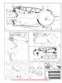 10
10
-
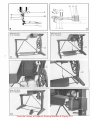 11
11


Adler 30 Operating Instructions Manual
- Categoría
- Máquinas de coser
- Tipo
- Operating Instructions Manual
Artículos relacionados
Otros documentos
-
 Duerkopp Adler 30 El manual del propietario
-
 Duerkopp Adler 220 Instrucciones de operación
-
 Duerkopp Adler 120 El manual del propietario
-
Alfa Network 659 Instruction book
-
Silvercrest SNMD 33 A1 Instrucciones de operación
-
Pfaff 1245 El manual del propietario
-
Medion MD11836 El manual del propietario
-
-
 Duerkopp Adler 220 Manual de usuario
-
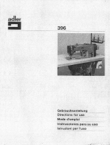 Duerkopp Adler 396 Instrucciones de operación


