
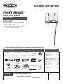
TOOLS REQUIRED TABLE OF CONTENTS
• Requires at least 493 lb (224 kg) of cement mix to fi ll a
volume of 3.7 ft3 (0,105 m3).
• Requires, at least, 3 days for concrete to cure, plus
3–4 hours to complete assembly steps.
• At least 2 people recommended for setup.
Pour le français, voir la page 2. Para el español, ver la página 3.
ASSEMBLY INSTRUCTIONS
MODEL 90599
Save this instruction in the event that the manufacturer must be contacted for replacement parts.
BEFORE ASSEMBLY:
CONTACT LIFETIME CUSTOMER SERVICE:
Dial 1-800-225-3865
QUESTIONS? Model Number: 90599
Product ID:
For Customer Service in Mainland Europe
and the United Kingdom,
E-mail: [email protected]
Live Chat:
www.lifetime.com/customerservice/home
(Click on the "LIVE CHAT" tab)
7/16" (≈11 mm)
(x2)
(x1)
(x1) (x1)
1/2" (≈13 mm)
(x2)
(x1)
9/16" (≈14 mm)
(x2)
3/4" (≈19 mm)
(x2)
(x1)
(x1)
Concrete Mix
493 lb (224 kg)
(x1)
(x1)
(x1)
Icon Legend...............................2
Warnings & Notices.....................3
Initial Setup...............................4
Pole Assembly..........................10
Backboard-to-Rim Assembly......14
Backboard-to-Pole Assembly......18
Parts Identifi er.........................i–iv
Handle Assembly......................23
Final Assembly.........................30
Maintenance............................35
Warning Sticker........................36
Registration........................38
Warranty................................39
FRONT ADJUST®
BASKETBALL SYSTEM
(x1)
Bricks (x8–10)

2
• Indicates the parts to be used for a section.
• Indicates special heed should be taken when reading.
• Indicates the hardware to be used for a section.
• Indicates the tools to be used for a section.
• Indicates no hardware required for a specifi c page.
• Indicates no parts required for a specifi c section.
• Indicates to use/not to use an electric drill for a specifi c step.
ICON LEGEND
• Indicates the use of a centerlock nut. A nut with this marking will require some effort to tighten.
This hardware was designed with this feature in order to prevent loosening later.

33
WARNINGS & NOTICES
Most injuries are caused by misuse and/or not following instructions. Use caution when using this product.
To ensure safety, do not attempt to assemble this product without following the instructions carefully. Check entire box and inside all packing
material for parts and/or additional instruction material. Before beginning assembly, read the instructions and identify parts using the hardware
identifi er and parts list in this document. Proper and complete assembly, use and supervision are essential for proper operation and to reduce the
risk of accident or injury. A high probability of serious injury exists if this product is not installed, maintained, and operated properly.
FAILURE TO FOLLOW THESE WARNINGS MAY RESULT IN SERIOUS INJURY OR PROPERTY DAMAGE AND WILL VOID WARRANTY.
Owner must ensure that all players know and follow these rules for safe operation of the system.
• If using a ladder during assembly, use extreme caution.
• Two capable adults are recommended for this operation.
• Check base daily for leakage. Leaks will cause system to fall.
• Assemble the pole sections properly. Failure to do so could cause the pole sections to separate during play or transport.
• Minimum operational height is 6 ft 6 in (1.98m) to the bottom of the backboard.
SAFETY INSTRUCTIONS

4
INITIAL SET UP
1
ALE (x1)
(x1)
(x1)
(x1)
(x1)
HARDWARE REQUIRED
PARTS REQUIRED
TOOLS REQUIRED
Metal Parts
Concrete mix
60-lb bags (≈x9)
(493 lb) (≈223,6 kg)
Bricks
(x8–10)

5
SECTION 1 (CONTINUED)
TOOLS AND HARDWARE REQUIRED
1
• IMPORTANT! Dig a round hole 24" (≈61 cm) deep and 18" (≈45.7 cm) in diameter. If you live in an area where frost heaves
may pose a problem, consult your local building inspector to determine the proper hole depth. The edge of the hole
should be fl ush with the edge of the playing surface.
!• A ground sleeve is available as an alternative to cementing the pole into the ground. Please contact Customer Service for more information.
• The edge of the 18" (≈45.7 cm) diameter hole should touch the edge of
the playing surface.
(x1)
(x1)
1.1
• Before digging, call to locate any buried utility lines.
• Avant de creuser, appelez pour localiser des utilités
publiques entérrées.
• Antes de cavar, llame para localizar las conexiones
de servicios públicos subterráneas.
CAUTION
! !
!
Playing Surface
Top view
24" (≈61 cm)
18" (≈45,7 cm)
Side view

6
SECTION 1 (CONTINUED)
TOOLS AND HARDWARE REQUIRED
• Stack bricks or patio blocks in the hole so the top of the stack measures 9.5" (≈24,1 cm) from the bottom of the hole (Fig.
1). The edge of the bricks should be about 2 1/2" (≈7 cm) from the playing surface (Fig. 2).
Fig. 1
Fig. 2
1.2
Playing Surface
24" (≈61cm)
18" (≈45,7 cm)
14.5"
(≈36,8 cm)
9.5"
(≈24,1 cm)
Side view
Top view
(x1)
2 1/2" (≈7 cm)
Bricks (x8–10)

7
SECTION 1 (CONTINUED)
TOOLS AND HARDWARE REQUIRED
1.2
(x1)
(x1)
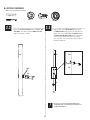
• Make a mark 14.5" (≈36.8 cm) from the dimpled end of the bottom pole (ALE) (do not scratch the
powder coating). Please, keep in mind this step when performing the next.
14.5 in/po (≈36.8 cm)
ALE
1.3
1.4
Concrete mix
420 lb (191 kg)
• Mix the concrete, following the directions on the bag.
Concrete mix
60-lb bag (≈x9)
(493 lb (≈223,6 kg))

8
SECTION 1 (CONTINUED)
TOOLS AND HARDWARE REQUIRED
1.5
!• Use a level to ensure the bottom pole is standing vertical. Form the cement into a downward slope away from the pole to allow water runoff. Failure to do
so may result in premature rusting of the pole.
(x1)
21" (≈53,3 cm)
18" (≈45,7 cm)
14.5"
(≈36,8 cm)
9.5"
(≈24,1 cm)
Side view
• 14.5" (≈36.8 cm) mark
18" (≈46 cm)
4" (≈10,2 cm)
Playing Surface
Fig. 1 Fig. 2
• Set the bottom of the bottom pole onto the bricks or patio blocks. The 14.5" (≈36.8 cm) mark on the pole should be fl ush with the playing
surface (Fig. 1). If it is not fl ush, the system will not adjust to the correct heights. The edge of the pole should be 4" (≈10.2 cm) from the playing surface
(Fig. 2) to ensure the back board overhangs the playing surface. If it is not, adjust it.
(x1)

9
SECTION 1 (CONTINUED)
TOOLS AND HARDWARE REQUIRED
• The slots at the top of the bottom pole must be parallel to the playing surface. Turn the pole, if necessary. Pour the mixed
concrete into the hole until it is fi lled to the level of the playing surface and the 14.5" (≈36,8 cm) mark on the pole.
Form the concrete into a downward slope away from the pole to allow for runoff. Allow the concrete to cure for 72 hours.
1.6
14.5" (≈36,8 cm) mark
Downward slope
Playing surface • Stop assembly now. Do not continue the assembly
until the concrete has been allowed to set for at
least 72 hours (3 days). In humid climates or wet
weather, allow more time for the concrete to cure.
Do not proceed until the curing process is complete.
!
!
• Ne pas continuer l’assemblage jusqu’à ce que le
béton ait été permis durcir, au moins, 72 heures
(3 jours). Sous les climats humides, laisser plus de
temps pour que le béton durcisse. Ne pas continuer
jusqu’à ce que le durcissement soit complète.
• Pausar el ensamblaje ahora. No continuar
el ensamblaje hasta que el concreto haya sido
permitido curar, por lo menos, 72 horas (3 días).
En climas húmedos, dejar más tiempo a que
el concreto se cure. No continuar hasta que el
endurecimiento se termine.
WARNING / AVERTISSEMENT
ADVERTENCIA
(x1)

10
POLE ASSEMBLY
2
BCO
Metal Part
Hardware Bag
TOOLS REQUIRED
PARTS REQUIRED
HARDWARE REQUIRED
(2) (1)
9/16”
ADS (x2)*
ABZ (x2)*
ABB (x2)
AAF (x2)
ABE (x2)
ABR (x2) CIH (x2)*
*Note: Only one #14 x 1” Self-Tapping Screw (ABZ), one Domed Countersink
Washer (CIH) and one 1/4” x 3/4” Pan Head Screw (ADS) will be used for
this section. Save the remaining hardware for later in the assembly.
Scrap Wood
ALH (x1)
ALF (x1)
Warning Sticker
ALL (x1)
(1) (1)

11
TOOLS AND HARDWARE REQUIRED
SECTION 2 (CONTINUED)
2.1 • Insert the 3/8” x 4” Hex Bolts (ABE) with the 3/8” Washers (AAF) into the Middle Pole (ALF) as shown. Then slide the 1/2” x
3.41” Spacers (ABR) onto the Hex Bolts.
ALF
ABE
ABR
Warning
Sticker
AAF
Large Holes
Small Holes
AAF (x2)
ABE (x2)
ABR (x2)

12
TOOLS AND HARDWARE REQUIRED
SECTION 2 (CONTINUED)
2.2 • Place the Pole Bracket (ALL) onto the 3/8” x 4” Hex
Bolts (ABE), and attach it to the Middle Pole (ALF)
with the hardware shown.
• The 1/4” x 3/4” Screw should be fl ush with the Pole,
but will spin freely once installed. Do not jam the Poles
together until instructed.
!
9/16" (x2)
2.3 • Align the hole in the Top Pole (ALH) with the slot in
the Middle Pole (ALF) and slide the Top Pole over the
Middle Pole. Insert a 1/4” x 3/4” Screw (ADS) through
a Domed Countersink Washer (CIH), into the small hole
in the Top Pole, and into the slot in the Middle
Pole as shown. The Screw head should fi t into the
Countersink Washer.
ALF
ABB
ALL
ABE
ABB (x2) ADS (x1)
ALH
ALF
ALH
ALF
ADS
CIH
CIH (x1)

13
TOOLS AND HARDWARE REQUIRED
SECTION 2 (CONTINUED)
• After the Poles have been seated, insert a #14 x 1”Self-Tapping Screw (ABZ) into the back of the Pole as shown.
2.5
2.4 • In order to seat the Poles, strike each end of the Pole very hard fi ve to six times on a piece of scrap wood or cardboard.
This must be done even if the Poles cover the slots before seating has occurred.
If the Top Pole (ALH) does not completely cover the slots on the Middle Pole (ALF) after seating, DO NOT COMPLETE ASSEMBLY. Call
our Customer Service Department.
WARNING
The poles must be seated together! Even if the poles cover
the slots before seating, they must be struck on a hard
surface fi ve to six times! Failure to seat the poles correctly
could allow the poles to separate during use, which could
lead to serious personal injuries or property damage.
Wood Block
ATTENTION: THIS STEP CANNOT BE REVERSED!
ALH
ALF
ALH
ALF
ABZ
ABZ (x1)
• Do not hit your feet with the Pole sections,
as serious injury could occur.
!
• THE SCREWS (ABZ) ARE DESIGNED TO DRILL
INTO THE METAL OF THE UNDERLYING POLE.
For ease of installation, chuck the Self-Drilling
Screws directly into the drill, or use a 3/8 in. (10
mm) Hex Driver.
!

14
BACKBOARD-TO-RIM ASSEMBLY
3
BCS
Metal Parts
Hardware Bag
PARTS REQUIRED
HARDWARE REQUIRED
ABD (x2)
5/16”
ABF (x2)
7/16”
AAM (x2)
ABK (x4)
5/16”
AJW (x2) APZ (x1)
AOW (x1)
AAV (x2)
DFE (x4)
AAA (x4)
AAJ (x2)
AJI (x1)
ALX (x1)
ALD (x1)
DFD (x1)
AMY (x2)
Plastic Parts
TOOLS REQUIRED
(2) (2) (2)
1/2” 7/16” 9/16”

15
TOOLS AND HARDWARE REQUIRED
SECTION 3 (CONTINUED)
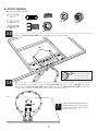
3.1 • Insert two Bolts (AAM) with Washers (ABD) and Rubber Washers (ABF) through the holes indicated in the back of the Rim (ALX) as
shown. Secure the hardware with two T-Nuts (AAJ).
1/2" (13 mm)
ABD (x2) ABF (x2)
AAM (x2)
AAJ (x2)
(x2)
(x1)
• Ensure that the tap bolts (AAM) are positioned on
the outside edge of the holes as shown.
• Do not overtighten the hardware so much that the
rubber washers bulge as shown.
!
!
AAJ
AAM
ABD
ABF
ALX
ABF ABF
AAJ
AAM
ABD
ABF

16
TOOLS AND HARDWARE REQUIRED
SECTION 3 (CONTINUED)
1/2” (x2)
3.2 • Connect the Rim (ALX) and Plastic Guard (ALD) to the Backboard (AJI) with the hardware shown. Secure the 5/16” Nylock Flange
Nuts (ABK) onto the Tap Bolts (AAM).
ABK (x2)
APZ (x1)
APZ
ALX
ABK
ALD
AAM
AJI
DFD

17
TOOLS AND HARDWARE REQUIRED
SECTION 3 (CONTINUED)
AAV
ABK
AOW
AJW
APZ
3.3
• Turn the Backboard Assemly over. Thread the 5/16” Jam Nuts (AAV) onto each end of the U-Bolt (APZ) as far as they
will go. Slide the Compression Springs (AJW) onto the U-Bolt, and place the Spring Retainer Plate (AOW) over the Com-
pression Springs. Secure the Plate to the Springs with the hardware shown.
• Attach the Backboard Brackets (AMY) to the Backboard using the hardware shown.
AAV (x2) ABK (x2)
AJW (x2)
AOW (x1)
1/2”(x2)
7/16”(x2)
9/16”(x2)
• DO NOT COMPLETELY TIGHTEN THE 5/16” NYLOCK
FLANGE NUTS IN THIS STEP! Only tighten the Nuts
until the Rim does not wobble. Tightening the Nuts
will adjust the Rim tension.
!
DFE (x4) AAA (x4)
AAA
DFE
DFE
DFE
DFE
AAA
AMY
• A Centerlock Nut
will require some effort
to thread onto a Bolt.
See page 2 for details.
3.4

18
7 5/8 in/po (≈19cm)
Metal Parts
Hardware Bag
TOOLS REQUIRED
PARTS REQUIRED
HARDWARE REQUIRED
4
(x2) (x2)
3/4" (≈19 mm) 9/16" (≈14 mm)
(x1)
BCR
AJY (x2)
AKC (x2)
AKB (x2)
AAX (x4)
ABB (x1)
AAD (x2)
GBU (x2)
DFC (x1)
7 1/16 in/po (≈18cm)
7 1/2 in/po (≈19cm)
7 1/2”
DGA (x2)
ABN (x8)
7 5/8 in/po (19.4 cm)
7 1/2 in (19 cm)
30 1/6 in (76.4 cm)
7 1/2 in/po (19 cm)
21 1/8 in (53.6 cm)
BACKBOARD-TO-POLE ASSEMBLY

19
SECTION 4 (CONTINUED)
TOOLS AND HARDWARE REQUIRED
4.1 • Attach the Short Extension Arms (AKC) to the Backboard Brackets in the location shown with the hardware indicated.
Secure only by hand at this point.
AKC
AKC
AAX ABN
ABN
DGA
AAX (x1)
ABN (x2)
DGA (x1)
3/4" (≈19 mm) (x2)
• DO NOT strike this Bolt (GBU) with a mallet!
If there is diffi culty sliding the Bolt into place,
use a wrench to turn the Bolt until it has
advanced into position.
!
• A Centerlock Nut requires
some effort to thread onto a
Bolt. See page 4 for details.
• If necessary, use a bolt to remove any
excess powder coating from the holes in the
Backboard Brackets.
!
GBU (x1)
GBU
7 5/8 in/po (≈19cm)

20
SECTION 4 (CONTINUED)
TOOLS AND HARDWARE REQUIRED
AKB AKB
AAX
ABB
DFC
DGA
GBU
AAX (x1)
DGA (x1)
9/16" (≈14 mm) (x2)
4.2 • Attach the ends of the Long Extension Arms (AKB) (that only have one hole)
to the Backboard Brackets in the location shown with the hardware
indicated. Secure only by hand at this point.
• Secure the Hex Bolt (DFC) to the
Backboard Brackets as shown.
4.3
ABB (x1)
DFC (x1)
7 1/2 in/po (≈19cm)
7 1/2”
7 1/2 in/po (19 cm)
3/4" (≈19 mm) (x2)
ABN (x2)
ABN
ABN
GBU (x1)
7 5/8 in/po (≈19cm)
7 5/8 in/po (19.4 cm)

i
This page intentionally left blank
PARTS IDENTIFIER
Detach this yellow section for use as a quick reference

ii
PARTS IDENTIFIER
Metal Parts
ALH (x1)
ALF (x1)
ALE (x1)
43 3/8” (110 cm)
Warning Sticker
ALL (x1)
ALX (x1)
DFD (x1)
AMY (x2)
AJY (x2)
AKC (x2)
AKB (x2)
AKQ (x1)
ALB (x1)
CNG (x1)
CNF (x1)
43 3/8”
Detach this yellow section for use as a quick reference

iii
PARTS IDENTIFIER
HARDWARE REQUIRED
Plastic Parts
BCO BCS BCR BCT BCU
AJI (x1)
ALD (x1)
ALM (x1)
AKI (x2)
AJS (x1)
AMN (x2)
AKP (x1)
CNJ (x1)
AKZ (x1)
AJX (x2)
AJQ (x1)
Detach this yellow section for use as a quick reference

iv
This page intentionally left blank
PARTS IDENTIFIER
Detach this yellow section for use as a quick reference

21
SECTION 4 (CONTINUED)
TOOLS AND HARDWARE REQUIRED
AAX (x1)
4.5
• Attach both Counterbalance Springs (AJY) to the Hex Bolt (DFC) as shown.
• Lay the Backboard assembly next to the Pole assembly. Rest the Rim on cardboard to prevent scratching. Then secure the
Short Extension Arms (AKC) to the Top Pole (ALH) with the hardware shown.
AJY
AAD
AAX
ABN ABN
AJY
DFC
AAD (x1)
7 1/16 in/po (≈18cm)
ABN (x2)
3/4" (≈19 mm) (x2)
4.4

22
SECTION 4 (CONTINUED)
TOOLS AND HARDWARE REQUIRED
AAX (x1)
4.6
4.7
• Secure the Short Extension Arms (AKC) to the Top Pole (ALH) with the hardware shown.
• Tighten the Nuts until they are fl ush with the end of each Bolt.
AAD
AAX ABN
ABN
AAD (x1)
7 1/16 in/po (≈18cm)
ABN (x2)
3/4" (≈19 mm) (x2)

23
HANDLE ASSEMBLY
5
Plastic Parts
PARTS REQUIRED
HARDWARE REQUIRED
BCT
Hardware Bag
Metal Part
ADR (x4)
AQH (x2)
CNI (x4)
AAC (x1)
AAN (x1)
7 in/po (≈18cm)
7”
AAX (x1)
ABO (x2)
ABB (x1)
AAD (x1) AAZ (x1)
AZP (x2)
CNE (x1)
CNH (x2)
AAJ (x4)
AKQ (x1)
ALB (x1)
AKI (x2)
AJS (x1) AMN (x2)
AKP (x1)
CNG (x1)
CNF (x1)
CNJ (x1)
TOOLS REQUIRED
(2)(2) (2)
3/4”1/2” 7/16”
(1)(1)
7 1/16 in/po (≈18cm)

24
SECTION 5 (CONTINUED)
TOOLS AND HARDWARE REQUIRED
5.1 5.2
ADR (x4)
CNG
AKI
AQH (x2)
AKI
• Attach the Lock Tab (CNF) to the Triggers (AMN) with
the hardware shown, and slide the Trigger Spring
(AQH) onto the Triggers in the locations shown.
• Position the Trigger Assembly onto the Handle
Brace (CNG) as shown. Place the Handle Grips (AKI)
on the Handle Brace over the Triggers.
AMN
AQH
ADR
CNF
AQH AMN
ADR ADR
ADR

25
SECTION 5 (CONTINUED)
TOOLS AND HARDWARE REQUIRED
5.3
5.4
• Secure the Handle Grips to the Handle Assembly with the hardware shown.
• Attach the Handle Assembly to the Outer Tube (ALB) with the hardware shown. Fit the Lock Tab (CNF) into the notch on
the Outer Tube.
CNH
AZP
Notch
CNI (x4) AAJ (x4)
CNH (x2)
CNH
ALB
AZP (x2)
AZP
CNI
CNI
CNI
CNI
AAJ
AAJ AAJ
AAJ
7/16”(x2)
• Make sure that the Inner Channel (AKQ) has
been removed from the Outer Tube before
performing this step.
!
Underside view

26
SECTION 5 (CONTINUED)
TOOLS AND HARDWARE REQUIRED
7.5’
10’
5.5
5.6
AKQ
AKP
CNE
Button snaps into the hole
CNJ
ALB
CNE (x1)
• Attach the Outer Tube Bushing (CNJ) to the Outer Tube (ALB).
• Slide the Two-Head Snap Button (CNE) into the hole at the top of the Inner Channel (AKQ). Orient the Height Sticker (AKP) as
shown and place it within the grooves of the Inner Channel. Line up the bottom end of the sticker with the edge of
the Inner Channel.
• Wipe off any grease that may be on the Inner
Channel before attaching the Height Sticker.
!

27
SECTION 5 (CONTINUED)
TOOLS AND HARDWARE REQUIRED
5.7
5.8
• While squeezing both Triggers (AMN), insert the notched end of the Inner Channel (AKQ) into the Outer Tube (ALB) as
shown. Slide the Inner Channel into the Outer Tube until the 10’ mark has been reached. Then release the
Trigger so it clicks into place.
• Insert the Channel Stop (AJS) into the top of the Outer Tube (ALB) as shown.
AKQ
ALB
AKQ
ALB 10’
ALB
AJS
AMN

28
SECTION 5 (CONTINUED)
TOOLS AND HARDWARE REQUIRED
5.10
AKQ
ALL
AAC (x1)
AAN (x1)
AAN
AAC
1/2”(x2)
3/4”(x2)
• Attach the Inner Channel (AKQ) to the Pole Bracket (ALL) with the hardware shown.
• Secure the Outer Tube (ALB) to the Long Extension Arms (AKB) with the hardware shown. If needed, use a Rubber Mallet to tap
the hardware into place.
• Do not overtighten the Cap Nut.
If the end of the Bolt breaks
through the plastic cap, call our
Customer Service Department.
Exposed threads on the end of the
Bolt may cause serious injuries.
• Tighten the Centerlock Nut (AAX)
until it is fl ush with the end of
the Bolt.
!
!ALB
AKB AKB
AAD
AAX
ABO
AAX (x1)
ABO (x2)
AAD (x1)
• A Centerlock Nut
will require some effort
to thread onto a Bolt.
See page 2 for details.
5.9
ABO
7 1/16 in/po (≈18cm)

29
SECTION 5 (CONTINUED)
TOOLS AND HARDWARE REQUIRED
5.11
5.12
• Insert the Hex Bolt (AAZ) through the holes in the Short Extension Arms (AKC) that are closest to the Pole. Secure the Hex
Bolt to the Short Extension Arms with a Centerlock Nut (ABB).
• Raise the Backboard to the highest position. Using the closed end of a wrench, stretch the Springs (AJY) up and over
the Hex Bolt (AAZ) one at a time as shown.
• Tighten the Centerlock Nut (ABB) until it
is fl ush with the end of the Bolt.
!
7 in/po (≈18cm)
7”
ABB (x1)
AAZ (x1)
AAZ
ABB
AKC AKC
(x1)
AJY
AAZ

30
Plastic Parts
TOOLS REQUIRED
PARTS REQUIRED
HARDWARE REQUIRED
FINAL ASSEMBLY
6
AKZ (x1)
(1) (1) (1) (1) (1)
AJX (x2)
AJQ (x1)
ADP (x10)*
#10 x 7/8”
(*Only eight of the 10 Screws will be used)
BCU
Hardware Bag
ADS (x1)
CIH (x1)
ABZ (x1)
BCO
(*This Hardware taken from the hardware bag used in Section 2.)
ALM (x1)

31
SECTION 6 (CONTINUED)
TOOLS AND HARDWARE REQUIRED
6.1
AJI
AJQ
ADP
ADP
ADP
ADP
ADP (x4)
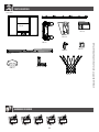
• Remove the plastic fi lm from the Backboard (AJI), and attach the Center Frame Pad (AJQ) to the Backboard in the
location shown with the hardware indicated. Make sure that the Center Frame Pad is centered on the metal piece
of the Backboard as shown.

32
TOOLS AND HARDWARE REQUIRED
SECTION 6 (CONTINUED)
6.56.2
ADP AJX
ADP
ADP
AJX
AJX
AJI
ADP (x6)
• Attach the Corner Frame Pads (AJX) to the Backboard (AJI) in the locations shown with the hardware indicated.
6.3
AKZ
ALX
• Attach the Net (ALX).
Note: If a replacement Net is needed, please call our Customer Service Department.
Our Nets are shorter than average to reduce the risk of entanglement.
!
!• The Corner Frame Pads (BAA and BAB) will overlap
the Center Frame Pad (AJQ).

33
SECTION 6 (CONTINUED)
TOOLS AND HARDWARE REQUIRED
To prevent serious injuries, two adults are
required to complete assembly.
• Make sure the Backboard faces the playing surface and
align the small hole in the Middle Pole (ALF)
with the correct
slot in the Bottom Pole (ALE). Slide the Middle Pole over the
Bottom Pole. Insert the remaining
1/4” x 3/4” Screw (ADS)
through the Countersink Washer (CIH)
and into the small hole
in the Middle Pole.
ALE
ALF
ALE
ADS
CIH
ALF
ADS (x1)
CIH (x1)
•
In order to seat the Poles, place the Scrap Wood on top of
the Pole and strike it very hard fi ve to six times with a Rubber
Mallet. This must be done even if the Poles cover the slots
before seating has occurred.
WARNING
The poles must be seated together! Even if the poles cover
the slots before seating, they must be struck on a hard
surface fi ve to six times! Failure to seat the poles correctly
could allow the poles to separate during use, which could
lead to serious personal injuries or property damage.
ATTENTION: THIS STEP CANNOT BE REVERSED!
6.4
6.5
• There are two screw holes at the bottom of the
pole. The correct hole will be slightly higher up on
the pole. The Screw will spin freely once installed.
!
•
If the Middle Pole does not completely cover the slot
on the Bottom Pole after seating, DO NOT COMPLETE
ASSEMBLY. Call our Customer Service Department.
!
SECTION 6 (CONTINUED)
TOOLS AND HARDWARE REQUIRED
To prevent serious injuries, two adults are
required to complete assembly.
• Make sure the Backboard faces the playing surface and
align the small hole in the Middle Pole (ALF) with the correct
slot in the Bottom Pole (ALE). Slide the Middle Pole over the
Bottom Pole. Insert the remaining 1/4” x 3/4” Screw (ADS)
through the Countersink Washer (CIH) and into the small hole
in the Middle Pole.
ALE
ALF
ALE
ADS
CIH
ALF
ADS (x1)
CIH (x1)
• In order to seat the Poles, place the Scrap Wood on top of
the Pole and strike it very hard fi ve to six times with a Rubber
Mallet. This must be done even if the Poles cover the slots
before seating has occurred.
WARNING
The poles must be seated together! Even if the poles cover
the slots before seating, they must be struck on a hard
surface fi ve to six times! Failure to seat the poles correctly
could allow the poles to separate during use, which could
lead to serious personal injuries or property damage.
ATTENTION: THIS STEP CANNOT BE REVERSED!
6.4 6.5
• There are two screw holes at the bottom of the
pole. The correct hole will be slightly higher up on
the pole. The Screw will spin freely once installed.
!
• If the Middle Pole does not completely cover the slot
on the Bottom Pole after seating, DO NOT COMPLETE
ASSEMBLY. Call our Customer Service Department.
!

34
TOOLS AND HARDWARE REQUIRED
SECTION 6 (CONTINUED)
ABZ (x1)
• After the Poles have been seated, insert a #14 x 1”Self-Tapping Screw (ABZ) directly into the back of the Middle Pole
just above where it meets the Bottom Pole.
ABZ
ALM
ALH
• Insert the Pole Cap (ALM) into the Top Pole (ALH) as shown.
6.6
6.7
• Chuck the #14 x 1” Self-Tapping Screw directly into
an Electric Drill for easy installation, or use a 3/8”
Hex Driver.
!

35
The life of your basketball system depends on many variables. The climate, exposure to corrosives such as salt, pesticides, or herbicides,
and excessive use or misuse can all contribute to Pole failure, which may cause property damage or personal injury.
Check your basketball system frequently for loose hardware, excessive wear, and signs of corrosion. For safety reasons, and to
prolong the life of your basketball system, you must take the following preventive measures.
a. Check all Nuts and Bolts. If any are loose, tighten them.
b. Check all parts for excessive wear and tear. If necessary, replace any parts that have been worn or damaged through usage.
Contact our Customer Service Department for replacement parts.
c. Inspect the Warning Sticker on the Pole. If it is ripped, faded, or illegible, call our Customer Service Department to request
a replacement Sticker.
d. Check all Pole sections for visible rust or chipped or cracked paint. If either are present, do the following:
1. Use an emery cloth to completely remove any rust or chipped paint.
2. Clean the area with a damp cloth and allow it to dry.
3. Apply two coats of a rust preventative, high gloss enamel paint to the area. Allow the paint to dry between coats.
IF RUST HAS PENETRATED THROUGH THE POLE ANYWHERE, REPLACE IT IMMEDIATELY!
MAINTENANCE

36
WARNING STICKER
FAUTE DE NE PAS SUIVRE CES AVERTISSEMENTS, VOUS RISQUEZ DE CAUSER
DES BLESSURES GRAVES ET/OU DES DOMMAGES À L’ÉQUIPEMENT.
Le propriétaire doit s’assurer que tous les joueurs con-
naissent et appliquent les règles suivantes afin d’utiliser
l’équipement en toute sécurité.
SI NO SE OBEDECEN ESTAS ADVERTENCIAS PUEDEN PRODUCIRSE
GRAVES LESIONES Y/O DAÑOS A LA PROPIEDAD.
El propietario del sistema debe asegurarse de que todos
los jugadores conozcan y respeten estas reglas para que el
sistema se use en forma segura.
WARNING
FAILURE TO FOLLOW THESE WARNINGS MAY RESULT IN SERIOUS INJURY
AND/OR PROPERTY DAMAGE.
Owners must ensure that all players know and follow these
rules for safe operation of the system.
• Only hang from the rim briefly to regain balance or avoid
injuring others. Release the rim as soon as safely possible.
• During play, especially when performing dunk type activities,
keep player’s face away from the backboard, rim, and net.
Serious injury could occur if teeth/face come in contact with
the backboard, rim, or net. Player should wear a mouth guard
during play.
• Do not slide, climb, or play on base or pole.
• When adjusting height or moving system, keep hands and
fingers away from moving parts.
• Do not allow children to move or adjust system.
• Do not wear jewelry (rings, watches, necklaces, etc.) during
play. Objects may entangle in net.
• Keep water and organic material away from pole base. grass,
litter, etc. could cause corrosion and/or deterioration.
• Never play on damaged equipment.
• Once a month check pole and all metal parts for signs of
corrosion (rust, pitting, chipping). Completely remove rust and
repaint with exterior enamel. If rust has penetrated any steel
part, replace that part immediately.
• Check system before each use for proper ballast, loose
hardware, excessive wear, instability, and signs of corrosion
and repair before use.
• Do not use the system to lift or hoist anything. The
mechanism is designed to lift only the weight of the
backboard and rim. Do not hang anything from the handle,
rim, backboard, or lifter arms as this will damage the system
and void the warranty.
• Ne pas se suspendre à l’anneau plus que nécessaire pour
retrouver l'équilibre ou éviter de blesser les autres joueurs.
Relâchez l’anneau aussitôt que possible.
• Lors d’un match, particulièrement dans le cas des smashs, le
visage du joueur ne doit pas faire face au panneau, à l’anneau, ni au
filet. Le joueur risque de graves blessures si ses dents ou son visage
entrent en contact avec le panneau, l’anneau, ou le filet. Les joueurs
doivent toujours porter un protège-dents lorsqu’ils jouent.
• Ne pas glisser, ne pas grimper, et ne pas jouer sur la base ou le
poteau.
• Lors du réglage de la hauteur ou lorsque du déplacement
de l’équipement, garder les mains et doigts loin des pièces mobiles.
• Ne permettre pas aux enfants de déplacer ou d’ajuster
l’équipement.
• Ne pas porter de bijoux (bagues, montres, colliers, etc.) pendant
le jeu. Ces objets pourraient s’accrocher au filet.
• Garder de l’eau et autre matiére organique loin de la base. Le
gazon, les déchets, etc. pourraient provoquer la corrosion et/ou la
détérioration.
• Une fois par mois, vérifier que le poteau et toutes les pièces en
métal ne montrent pas de signes de corrosion (rouille, piqûres,
écaillage). Enlever toute la rouille et repeindre complètement avec
une peinture pour extérieur. Si la rouille a pénétré une des pièces en
acier, il faut remplacer immédiatement la pièce en question.
• A chaque utilisation de l’équipement, vérifier d’abord l’équilibre, la
possibilité de pièces desserrées ou usées, la stabilité de
l’équipement et tout signe de corrosion ou réparation nécessaire
avant utilisation.
• Ne jamais jouer avec un équipement endommagé.
•Ne pas utiliser l’équipement pour lever ou soulever quoique ce
soit. Son mécanisme a été conçu uniquement pour soutenir le poids
du panneau et de l’anneau. Ne rien accrocher au manche, à
l’anneau, au panneau ni aux leviers sous peine d’endommager
l’équipement et d’annuler la garantie.
• Cuélguese del aro sólo en forma breve, para recuperar el equilibrio
o evitar lesionar a otros jugadores. Suéltese del aro lo más pronto
que pueda hacerlo con seguridad.
•Durante el juego, especialmente al embocar violentamente de
alto, la cara de los jugadores debe mantenerse alejada del tablero,
el aro y la red. Pueden producirse lesiones graves si los dientes o la
cara entran en contacto con el tablero, el aro o la red. Los jugadores
deben usar un protector bucal durante el juego.
•No se deslice, no trepe ni juegue sobre la base o el poste.
•Mantenga las manos y los dedos alejados de las piezas
movibles cuando regule la altura o desplace el sistema.
•No deje que los niños regulen ni desplacen el sistema.
•No use joyas (anillos, relojes, collares o gargantillas, etc.) durante el
juego. Estos objetos pueden engancharse en la red.
•Guarde aqua y materia orgánica. Césped, basura,etc., prodrian
causar corrosión et/o deterioros.
•Controle el poste y todas las piezas metálicas una vez al mes
en busca de signos visibles de corrosión (oxidación, picaduras,
escamado). Elimine todo rastro de óxido y vuelva a pintar con
esmalte para exteriores. Si el óxido ha penetrado cualquier pieza de
acero, reemplace esa pieza de inmediato.
•Inspeccione el sistema antes de cada uso para verificar que esté
adecuadamente contrapesado, que los elementos de fijación no
estén flojos, que no haya desgaste excesivo, inestabilidad ni signos
de corrosión. Si encuentra irregularidades, repárelas antes de usar
el sistema.
•Nunca juegue con un equipo dañado.
•No use el sistema para levantar ningún objeto. El mecanismo
está diseñado para elevar solamente el peso del tablero con el
aro. No cuelgue nada de la agarradera, el aro, el tablero ni los
brazos de elevación, ya que esto puede dañar el sistema y anular la
garantía.
www.lifetime.com # 1176611
ADVERTENCIAAVERTISSEMENT
Lifetime Products, Inc., Clearfield, UT 84016
1-800-225-3865 7/12/2016

37
NOTES

3838
LIFETIME’S PROMISE TO YOU:
We invite you to read our privacy policy at www.lifetime.com
REGISTER today!
At Lifetime®, we are committed to providing innovative and quality products. While registering, you will have the opportunity to give us your feedback. Your input is
valuable to us.
• You can also opt in to receive new product notifi cations or promotions.
• In the unlikely event of a product recall or safety modifi cation, your registration provides the information we need to notify you directly.
• Registration is fast, easy, and completely voluntary.
Maintaining your privacy is our long-standing policy at Lifetime®. And you can rest assured that Lifetime® will not sell or provide your personal data to other third parties,
or allow them to use your personal data for their own purposes.
LA PROMESA DE LIFETIME® PARA USTED:
Lo invitamos a leer nuestra política de privacidad en www.lifetime.com (sólo en inglés)
¡REGISTRARSE hoy mismo!
En Lifetime®, estamos comprometidos a ofrecer productos innovadores y de calidad. Al registrarse, usted tendrá la oportunidad de darnos su retroalimentación. Su
información es valiosa para nosotros.
• También puede optar por recibir nuestras notifi caciones o promociones.
• En el caso improbable de que el producto deba ser retirado del mercado o que sufra alguna modifi cación, su registro provee la
información que necesitamos para notifi carle directamente.
• El registro es rápido, fácil y completamente voluntario.
Mantener privacidad es nuestra política permanente en Lifetime®. Y puede estar seguro que Lifetime® no venderá ni dará datos personales a terceros, ni les permitirá usar
datos personales para sus propios fi nes.
LA PROMESSE DE LIFETIME :
Nous vous invitons à lire notre politique de confi dentialité à www.lifetime.com (en anglais seulement)
ENREGISTRER CE PRODUIT aujourd’hui!
Chez Lifetime®, nous nous engageons à fournir des produits innovateurs de qualité. Lors de votre inscription, vous aurez l’occasion de nous faire parvenir vos com-
mentaires. Votre opinion est importante pour nous.
• On peut également choisir de recevoir des avis ou des promotions dans le cadre de nouveaux produits.
• Dans l’éventualité peu probable d’un rappel ou d’un avis de sécurité, l’inscription fournit les renseignements nécessaires nous
permettant de communiquer avec vous.
• L’inscription est rapide, facile et complètement volontaire.
Conserver votre confi dentialité est notre politique de longue date chez Lifetime®. Vous pouvez donc être rassuré par le fait que Lifetime® ne vendra pas ou ne fournira
pas vos données personnelles à des tiers, et ne leur permettra pas d’utiliser vos données personnelles à leurs propres fi ns.
REGISTER YOUR PRODUCT ONLINE AT WWW.LIFETIME.COM
REGISTRAR EL PRODUCTO EN LÍNEA EN WWW.LIFETIME.COM
ENREGISTRER CE PRODUIT EN LIGNE À WWW.LIFETIME.COM

39
THE MANUFACTURER RESERVES THE RIGHT TO MAKE SUBSTITUTIONS TO WARRANTY CLAIMS IF PARTS ARE UNAVAILABLE OR OBSOLETE.
1. Lifetime basketball systems are warranted to the original purchaser to be free from defects in material or workmanship for a
period of fi ve years (60 months) from the date of original retail purchase. The word “defects” is defi ned as imperfections that
impair the use of the product. Defects resulting from misuse, abuse or negligence will void this warranty. This warranty does not
cover defects due to improper installation, alteration or accident. This warranty does not cover damage caused by vandalism,
rusting, “acts of nature” or any other event beyond the control of the manufacturer.
2. This warranty is nontransferable and is expressly limited to the repair or replacement of defective product. If the product is
defective within the terms of this warranty, Lifetime Products, Inc. will repair or replace defective parts at no cost to the purchaser.
Shipping charges to and from the factory or distribution center are not covered and are the responsibility of the purchaser. Labor
charges and related expenses for removal, installation or replacement of the product or its components are not covered under
this warranty.
3. This warranty does not cover scratching or scu ng of the product that may result from normal usage. In addition, defects
resulting from intentional damage, negligence, unreasonable use or hanging from the rim will void this warranty.
4. Liability for incidental or consequential damages is excluded to the extent permitted by law. While every attempt is made to
embody the highest degree of safety in all equipment, freedom from injury cannot be guaranteed. The user assumes all risk of
injury resulting from the use of this product. All merchandise is sold on this condition, and no representative of the company
may waive or change this policy.
5. This product is not intended for institutional or commercial use; Lifetime Products, Inc. does not assume any liability for such use.
Institutional or commercial use will void the warranty.
6. Our goods come with guarantees that cannot be excluded under the Australian Consumer Law. You are entitled to a replacement
or refund for a major failure and for compensation for any other reasonably foreseeable loss or damage. You are also entitled to
have the goods repaired or replaced if the goods fail to be of acceptable quality and the failure does not amount to a major failure.
7. This warranty is expressly in lieu of all other warranties, expressed or implied, including warranties of merchantability or fi tness
for use to extent permitted by Federal and state law. Neither Lifetime Products, Inc., nor any representative assumes any other
liability in connection with this product. This warranty gives you specifi c legal rights, and you may also have other rights which
vary from state to state.
www.lifetime.com
PLEASE INCLUDE YOUR DATED SALES RECEIPT AND PHOTOGRAPHS OF DAMAGED PARTS.
REPORT PRODUCT DEFECTS IN WRITING TO:
Lifetime Products, Inc., PO Box 160010 Clearfi eld, UT 84016-0010 or dial 1-800-225-3865.
REGISTER YOUR PRODUCT FOR QUICKER CUSTOMER SERVICE.
Visit www.lifetime.com or dial 1-800-225-3865 to register your product today.
FOR INTERNATIONAL WARRANTY CLAIMS:
All warranty claims must be accompanied by a sales receipt. Report all warranty claims in writing to your regional sales
support representative. Please include your dated sales receipt and photographs of damaged parts.
To Identify the representative for your region, please visit: www.lifetime.com/international
5-YEAR LIMITED FACTORY WARRANTY
W
A
R
R
A
N
T
Y
W
A
R
R
A
N
T
Y
WARRANTY

40
www.lifetime.com
Or dial 1-800-424-3865
To purchase accessories or other Lifetime® products, visit us at:
www.lifetime.com
ENHANCE YOUR LIFETIME® PURCHASE BY ADDING ACCESSORIES OR OTHER GREAT PRODUCTS
40
1232991 10/20/2023
-
 1
1
-
 2
2
-
 3
3
-
 4
4
-
 5
5
-
 6
6
-
 7
7
-
 8
8
-
 9
9
-
 10
10
-
 11
11
-
 12
12
-
 13
13
-
 14
14
-
 15
15
-
 16
16
-
 17
17
-
 18
18
-
 19
19
-
 20
20
-
 21
21
-
 22
22
-
 23
23
-
 24
24
-
 25
25
-
 26
26
-
 27
27
-
 28
28
-
 29
29
-
 30
30
-
 31
31
-
 32
32
-
 33
33
-
 34
34
-
 35
35
-
 36
36
-
 37
37
-
 38
38
-
 39
39
-
 40
40
-
 41
41
-
 42
42
-
 43
43
-
 44
44


en otros idiomas
- français: Lifetime 90599 Le manuel du propriétaire
- English: Lifetime 90599 Owner's manual
Artículos relacionados
-
Lifetime 1558 El manual del propietario
-
-
-
-
-
-
-