
Changer Control
Audio Master
Installation/Connections
Instalación/Conexiones
ƒw‚¸¡ ‰u‚ ‡s–
WX-C5000
Sony Corporation 2000 Printed in Japan
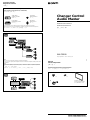
Parts list
Lista de componentes
„s¥ ⁄@˜ “
The numbers in the list are keyed to those in the instructions.
Los números de la lista corresponden a los de las instrucciones.
„s¥ “ ⁄⁄“”…˘ƒr»P»¡'œ⁄ ⁄⁄“”…˘ƒr‹O⁄@›P“”¡C
12 3
4
× 6 × 6
For NISSAN cars only
Sólo para automóviles NISSAN
¶¨ A¥˛ NISSAN ⁄؆£ P¤T¤fi
*I-3-048-533-11*(1)
Connection diagram
Diagrama de conexión
– ‰u„ˇ
Equipment used in illustrations (not supplied)
Equipo utilizado en las ilustraciones (no suministrado)
„ˇ¥ ¥˛‡]‡˘¡]«D“ –a¡^
A
BUS AUDIO
IN
BUS IN
BUS AUDIO
IN
BUS
CONTROL IN
AUDIO OUT
REAR
AUDIO OUT
FRONT
SUB OUT
B
Source selector
Selector de fuente
«H‚„•‰¿ „
CD/MD changer
Cambiador de CD/MD
CD/MD ·«”— „
Power amplifier
Amplificador de potencia
¥\†v'æ⁄j „
Front speakers
Altavoces delanteros
«e·›`n „
Rear speakers
Altavoces traseros
«Æ·›`n „
For connecting two or more changers, the source selector XA-C30 (optional) is necessary.
Cuando desee conectar dos o más cambiadores, necesitará un selector de fuente XA-C30 (opcional).
‡s– 2 ‹[¥H⁄W·«”— „fi ¡A¥†¶•¤ˇ¥˛«H‚„•‰¿ „ XA-C30¡]¿ `˚¥ ¡^
¡C
Notes
• Be sure to connect the earth cord before connecting the amplifier.
• If you connect an optional power amplifier and do not use the built-in amplifier, the beep sound will be
deactivated.
Notas
• Asegúrese de conectar primero el cable de puesta a masa antes de realizar la conexión al amplificador.
• Si conecta un amplificador de potencia opcional y no utiliza el incorporado, los pitidos se desactivarán.
ø
•
¨¥†ƒb– 'æ⁄j „⁄§«e‡s– ƒa‰u¡C
•
ƒp“G–z‡s– ⁄F¿ `˚¥ “”¥\†v'æ⁄j „ƒ ⁄£¤ˇ¥˛⁄”‚¸“”'æ⁄j „¡A–N L„˚`n¥\fl
¡C

Installation Instalación
¤ˇ¥˛«e¶•“‘•N
•¥» ⁄W›–“” 4 › ⁄ ‰—⁄£›n•o§¸¡C¥ƒ› ¶¨¤ ”ß› § ‡N
⁄H›ß‰ ª‰ ¿ „⁄§¥˛¡C
•¥» ¶•ƒw‚¸ƒb⁄£§«ˆ“ r p“”ƒ ‚m¡C
•` §K§ ¥» 'æƒb “•¯⁄§‡B¡Aƒp¶§¥œ“‰– • fig¡B•xfi
«e¡B'˛ƒ˙„—•¥ƒh¡A»Œ¯…'˛' ¥˝ _ ˚ ¥ƒa⁄Ł¡C
•‹ ⁄Fƒw¥ _¤£¡Aƒw‚¸fi ‰—¤ˇ¥˛“ –a“”⁄u¤ª¡C
ƒw‚¸¤⁄« ⁄§‰ ª
‰—ƒb 20 « ¥H⁄”‰ ªƒw‚¸¤⁄« ¡C
Precauciones
•No toque los cuatro orificios de la superficie
superior de la unidad. Estos orificios son para
ajustes del sintonizador que solamente deberán
realizar técnicos de reparación.
•Elija cuidadosamente el lugar de montaje de
forma que la unidad no interfiera las funciones
normales de conducción.
•Evite instalar la unidad donde pueda quedar
sometida a altas temperaturas, como a la luz
solar directa o al aire de calefacción, o a polvo,
suciedad, o vibraciones excesivas.
•Para realizar una instalación segura y firme,
utilice solamente la ferretería de montaje
suministrada.
Ajuste del ángulo de montaje
Ajuste el ángulo de montaje a menos de 20°.
ƒw‚¸
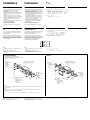
Precautions
•Do not tamper with the four holes on the upper
surface of the unit. They are for tuner
adjustments to be done only by service
technicians.
•Choose the installation location carefully so that
the unit will not hamper the driver during
driving.
•Avoid installing the unit where it would be
subject to high temperatures, such as from direct
sunlight or hot air from the heater, or where it
would be subject to dust, dirt or excessive
vibration.
•Use only the supplied mounting hardware for a
safe and secure installation.
Mounting angle adjustment
Adjust the mounting angle to less than 20°.
Mounting the unit in a Japanese
car
You may not be able to install this unit in some
makes of Japanese cars. In such a case, consult
your Sony dealer.
When mounting this unit to the preinstalled
brackets of your car, use the supplied screws 1 or
2 in the appropriate screw holes, according to
your vehicle: T for TOYOTA, M for MITSUBISHI,
and N for NISSAN.
Montaje de la unidad en un
automóvil japonés
Es posible que no pueda instalar esta unidad en
algunos automóviles japoneses. En tal caso,
consulte a su proveedor Sony.
Cuando monte esta unidad en los soportes
preinstalados de su automóvil, utilice los tornillos
suministrados 1 o 2 de esta unidad y móntelo
en los orificios de montaje adecuados para el
vehículo: T (para TOYOTA), M (para
MITSUBISHI) y N (para NISSAN).
–N¥» ƒw‚¸' ⁄Ø¥»†£¤T¤fi‚
ƒ‡“”⁄Ø¥»†£¤T¤fi⁄£fl ƒw‚¸¥» ¡Cƒ„fi ¡A‰—‹¢‚
• ƒa“” Sony ‚g P ¡C
• –z§ “ –a“”ƒ«‹[ƒw‚¸¤ ¥» fi ¡A ‰—¤ˇ¥˛¥»
“ –a“”`‡ v 1 '˛ 2¡A§ ¥ƒƒw‚¸¤ –z¤T¤fi¥˛“”‹ •
“”ƒw‚¸⁄ ⁄W¡GT¡]¥˛' TOYOTA¡^¡AM ¡]¥˛'
MITSUBISHI¡^¡A¥H⁄˛ N¡]¥˛'NISSAN¡^¡C
Notes
• Do not apply excessive force to the buttons of the
unit.
• Do not push on the display window.
• Before mounting, make sure there is nothing on top
of the unit.
Notas
• No emplee los botones de la unidad con excesiva
fuerza.
• No ejerza presión sobre el visualizador.
• Antes de realizar el montaje, asegúrese de que no
hay nada sobre la unidad.
ø
•
¥» “”« ¶s⁄`⁄¯„L⁄j¥˛⁄O« £
¡C
•
⁄`⁄¯« £¯ª¥ «
¡C
•
ƒw‚¸«e¡A ¨¥†‰T»{¥» ‡»⁄W¤Sƒ‡¥ ƒ “«¯Ø
¡C
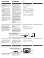
TOYOTA/MITSUBISHI
This illustration is for TOYOTA cars.
Esta ilustración es para automóviles TOYOTA.
TOYOTA ´ ¥— P¤T¤fi„ˇ¥ ¡C
1 or 2
max. size 5 × 8 mm
1 o 2
Tamaño máx.:
5 × 8mm
1 '˛ 2
‡ ⁄j⁄ ⁄o 5¡8 mm
to dashboard/center console
al salpicadero/consola central
ƒ » “ “O¡ ⁄⁄¥¡––¤ ‰c
Bracket
Soporte
ƒ«‹[
NISSAN
1 max. size
5 × 8 mm
Tamaño máx.:
5 × 8mm
‡ ⁄j⁄ ⁄o
5¡ 8 mm
to dashboard/center console
al salpicadero/consola central
ƒ » “ “O¡ ⁄⁄¥¡––¤ ‰c
1 max. size
5 × 8 mm
Tamaño máx.:
5 × 8mm
‡ ⁄j⁄ ⁄o
5¡ 8 mm
Note
To prevent malfunction, be sure to install using
brackets and the supplied screws 1 or 2.
Existing parts supplied to
your car
Piezas existentes
suministradas con su
automóvil
H¤T¤fi“ –a“”‡¡¥
3
Nota
Para evitar fallos de funcionamiento, asegúrese de
utilizar soportes y los tornillos 1 o 2 suministrados
para realizar la instalación.
ø
‹ ¤ ⁄ o¥˝‹G» ¡Aƒw‚¸fi ¨¥†¤ˇ¥˛ƒ«‹[¥H⁄˛“ –a“”`‡ •
1
'˛
2¡C
1 or 2
max. size 5 × 8 mm
1 o 2
Tamaño máx.:
5 × 8mm
1 '˛ 2
‡ ⁄j⁄ ⁄o 5¡8 mm
Note
Use the screws 1 or 2 depending on the make of car. When this unit is attached to a MITSUBISHI car, use the
supplied screws 2.
Nota
Utilice los tornillos 1 o 2 en función de la marca del automóvil. Si instala esta unidad en un automóvil
MITSUBISHI, emplee los tornillos 2 suministrados.
ø
‰—« • ¤T¤fi…t P¿ ¥˛`‡ v
1
'˛
2
¡C§ ¥»‚¸‚mƒw‚¸ƒb MITSUBISHI ⁄T ¤T¤fifi ¡A‰—§Q¥˛“ –a“”`‡ v
2
¡C
Existing parts supplied to
your car
Piezas existentes
suministradas con su
automóvil
H¤T¤fi“ –a“”‡¡¥
Bracket
Soporte
ƒ«‹[

Conexiones
Precauciones
•Esta unidad ha sido diseñada para alimentarse
con 12 V CC, negativo a masa, solamente.
•Antes de realizar las conexiones, desactive el
encendido del automóvil para evitar
cortocircuitos.
•Tenga cuidado de no atrapar ningún cable entre
el tornillo y la carrocería del automóvil o esta
unidad, o entre las partes móviles, como el raíl
de los asientos, etc.
•Conecte los cables de entrada de alimentación
amarillo y rojo solamente después de haber
conectado los demás.
•Cerciórese de conectar el cable de entrada de
alimentación rojo a un terminal de 12 V positivo
que se energice al poner la llave de encendido en
la posición auxiliar.
•Conecte todos los cables de puesta a masa a
un punto común.
•Conecte el cable amarillo a un circuito libre del
automóvil que tenga una capacidad superior a la
del fusible de la unidad. Si conecta esta unidad
en serie con otros componentes estereofónicos,
el circuito del automóvil al que se encuentran
conectados debe tener una capacidad superior a
la de la suma de las capacidades de los fusibles
de cada componente. Si ningún circuito del
automóvil tiene una capacidad tan alta como la
del fusible de la unidad, conecte ésta
directamente a la batería. Si el automóvil no
dispone de ningún circuito para conectar esta
unidad, conéctela a un circuito del automóvil
con capacidad superior a la del fusible de la
unidad, de forma que si se funde el fusible de
ésta, no se interrumpa ningún otro circuito.
•Cuando sustituya el fusible, compruebe que
utiliza uno con el amperaje especificado en el
fusible. Si éste se funde, compruebe la conexión
de alimentación y sustitúyalo. Si una vez
sustituido vuelve a fundirse, es posible que
exista un funcionamiento defectuoso interno. En
este caso, póngase en contacto con el proveedor
Sony más próximo.
•Por razones de seguridad, asegúrese de aislar
con cinta eléctrica los cables sueltos que no estén
conectados.
‡s–
“‘•N
•¥» ¥ufl ¤ˇ¥˛›t•¥– ƒa 12 V “‰‹y„q•‰¡C
•¶iƒ ‡s– ⁄§«e¡A‰—¥ ˆ ‡‹¤T¤fi“”´I⁄ı „¡A¥H` §K u
‚¡C
• ¨¥†⁄p⁄ ¡A⁄£›n¯ „q‰u‡Q§¤ƒb`‡ • O¤fi¤›⁄§¶¡¡A'˛
‡Q¥»‚¸‚m§¤ƒ ¡A'˛‡Q¥ ƒ ˇœˆ “”¥i† ˚‡¡¥ ¡A¤ ƒp
¤fifiy⁄U“”›y„D ¥§¤ƒ ¡C
•‹ıƒ 'M¶ ƒ „q•‰¿Ø⁄J ‰u¥†¶•ƒb' ƒ‡¤ ¥L ‰u‡£‡s
– §„†ƒ¥H«Æ⁄~‡s– ¡C
•‹ıƒ „q•‰ ‰u ¨‰—‡s– ƒ ¥¿ 12 V „q•‰” ⁄l¡]‚ „q
•‰” ⁄lƒb´I⁄ı˘_ ˝´ ¤ »†§Uƒ ‚mfi ⁄~‡q„q¡^¡C
•–N' ƒ‡ƒa‰u‡£‡s– ¤ ƒP⁄@ƒa´I¡C
•–N¶ ƒ ‰u‡s– ¤ ⁄j' „«O I •ˆB'wfie¶q“”¥…ƒß
¥˛“”¤T¤fi„q‚ ⁄W¡C
›Y§ ¥» 'M¤ ¥L¥ ¯Ø`n† ƒ¤ ‹ ⁄‹ƒŒ`p¡A' ‡s–
“”¤T¤fi„q‚ fie¶q¥†¶•⁄j' ƒU† ƒ¤ «O I •fie¶q“”
`‘'M¡C›Y¤Sƒ‡»P¥» «O I •ˆB'wfie¶q⁄@…¸⁄j“”¤T
¤fi„q‚ ¥i§Q¥˛¡A¥i§ ¥» “‰– ‡s– ¤ „qƒ ⁄W¡C›Y
L A• “”¤T¤fi„q‚ ¥i¥˛' ‡s– ¥» ¡A‰—§ ¥» ‡s
– ¤ ⁄j' ¥» «O I •fie¶q“”¤T¤fi„q‚ ⁄W¡Cƒpƒ„¡A
«h§Y¤ˇ¥» “”«O I •¿N´_⁄F¡A ⁄]⁄£›P' ⁄`´_¤ ¥L
„q‚ ¡C
•§ ·««O I •fi ¡A¥†¶•‰T«O' § ·«“”«O I •†¯ƒX‡W'w
“”„q‹y‰d‡ ¡C›Y«O I •¿N´_¡A‰— ¸‹d„q•‰‡s– ¤ˆƒA
§ ·««O I •¡C›Y«O I •§ ·««Æ⁄S‡Q¿N´_¡A«h¥ifl ‹O
⁄”‡¡‹G» ¡Cƒb‡o” –¡“p⁄U¡A‰—ƒV“ “æ“” Sony ‚g P
¿‚¡C
•‹ ⁄Fƒw¥ ¡A‰—‰T»{§ ¤Sƒ‡‡s– “” ‰u¥˛„q „‰ƒ–a¥]
†ˇ¶iƒ ·‰t¡C
Connections
–z“”¤T¤fi o ˚ ´I⁄ı˘_ ˝¶}ˆ ƒp“G
¤Sƒ‡»†§Uƒ ‚m
— POWER SELECT ¶}ˆ
«e›–“O“”• 'œ“”⁄u…t‡]'w‹ ON¡C§Y¤ˇ⁄£¤ˇ¥˛fi
⁄]´I«G¡C›Y›nƒb´I⁄ı˘_ ˝¶}ˆ ¤Sƒ‡»†§Uƒ ‚m“”¤T¤fi‚
¤ˇ¥˛¥» fi¡Aƒ„• 'œ¿O–N‚g–‘ƒbfiłfl •L¶q“”„qƒ „q
⁄O¡C‹ ⁄F` §Kfiłfl „qƒ ¡A‰—§ ¥» ¥“ …“” POWER
SELECT ¶}ˆ ‡]'wƒb B¡A M«Æ« «e“O“”›«‰ `¡A«K
¥i¯ ¥» ƒb⁄£¤ˇ¥˛fi ⁄]⁄£´I«G• 'œ¡C
Caution
•This unit is designed for negative ground 12 V
DC operation only.
•Before making connections, turn the car ignition
off to avoid short circuits.
•Be careful not to pinch any wires between the
screw and the body of the car, or this unit, or
between any moving parts such as the seat
railing, etc.
•Connect the yellow and red power input leads
only after all other leads have been connected.
•Be sure to connect the red power input lead to
the positive 12 V power terminal which is
energized when the ignition key is in the
accessory position.
•Run all ground wires to a common earth
point.
•Connect the yellow cord to a free car circuit
rated higher than the unit’s fuse rating. If you
connect this unit in series with other stereo
components, the car circuit they are connected to
must be rated higher than the sum of the
individual component’s fuse rating. If there are
no car circuits rated as high as the unit’s fuse
rating, connect the unit directly to the battery. If
no car circuits are available for connecting this
unit, connect the unit to a car circuit rated higher
than the unit’s fuse rating in such a way that if
the unit blows its fuse, no other circuits will be
cut off.
•When replacing the fuse, be sure to use one that
matches the amperage described on the fuse. If
the fuse blows, check the power connection and
replace the fuse. If the fuse blows again after
replacement, there may be an internal
malfunction. In such a case, consult your nearest
Sony dealer.
•Be sure to insulate any loose unconnected wires
with electrical tape for safety.
Selector de frecuencia
El intervalo de sintonía de AM (FM) ha sido
ajustado en fábrica a la posición 9 K (50 K). Si el
sistema de asignación de frecuencias de su país se
basa en el intervalo de 10 kHz (200 kHz), ponga
este selector, situado en el lado izquierdo de la
unidad, en la posición 10 K (200 K) antes de
realizar las conexiones.
Una vez ajustado el selector de frecuencia, debe
presionar el botón de restauración para restaurar
la unidad.
Frequency select switch
The AM (FM) tuning interval is factory-set to the
9 K (50 K) position. If the frequency allocation
system of your country is based on 10 kHz (200
kHz) interval, set the switch on the left side of
the unit to the 10 K (200 K) position before
making connections.
After the frequency select switch is set, you must
press the reset button to reset the unit.
W†v¿ ¶}ˆ
AM (FM) ‰ ¿ ¶¡„j“”⁄u…t‡]'w‹Oƒb 9 K (50 K) ƒ
‚m¡C›Y¶Q Œ“” W†v⁄ t¤t†˛‹O¥H 10 kHz (200 kHz) ¶¡
„j‹ ´ƒ¡A‡s– «e¡A‰—–N¥» ¥“ …⁄W“”¶}ˆ ‡]'wƒb
10 K (200 K) ƒ ‚m⁄W¡C
W†v¿ ¶}ˆ ‡]'w§„†ƒƒZ¡A¥†¶•« £›«‰ «
` ¡A¤ˇ¥»‚¸‚m˛ ƒ ¡C
Reset button
When the installation and connections are over, be
sure to press the reset button with a ballpoint pen,
etc.
Botón de restauración
Cuando finalice la instalación y las conexiones,
cerciórese de presionar el botón de restauración
con un bolígrafo, etc.
›«‰«¶s
ƒw‚¸'M– ‰u§„†ƒ«Æ¡A‰—¥˛› ⁄l § ¥« £›«‰ «
¶s¡C
Reset button
Botón de reposición
›«‰«¶s
If your car has no accessory
position on the ignition key
switch — POWER SELECT switch
The illumination on the front panel is factory-set
to be turned on even when the unit is not being
played. However, this setting may cause some car
battery wear if your car has no accessory
position on the ignition key switch. To avoid
this battery wear, set the POWER SELECT switch
located on the left side of the unit to the B
position, then press the reset button. The
illumination is reset to stay off while the unit is
not being played.
Si el automóvil no dispone de
posición auxiliar en la llave de
encendido
— Selector POWER SELECT
La iluminación del panel frontal ha sido ajustada
en fábrica para que esté activada aunque la
unidad no se encuentre en reproducción. Sin
embargo, este ajuste puede provocar cierta
descarga de la batería del automóvil si éste no
dispone de posición auxiliar en la llave de
encendido. Para evitar esto, ponga el selector
POWER SELECT, situado en el lado izquierdo de
la unidad, en la posición B y, después,
presione el botón de restauración. La
iluminación estará desactivada cuando la unidad
no se encuentre en reproducción.
Frequency select switch
Selector de frecuencia
W†v¿ ¶}ˆ
POWER SELECT switch
Selector POWER SELECT
POWER SELECT („q•‰¿ ) ¶}ˆ
Note
When you connect the power supply cord to the unit
or reset the unit, wait for about 10 seconds before
you insert a disc. If you insert a disc within these 10
seconds, the unit will not be reset, and you will have
to press the reset button again.
Nota
Cuando conecte el cable de suministro de
alimentación a la unidad o cuando restaure ésta,
espere unos 10 segundos antes de insertar algún disco.
Si inserta un disco antes de que transcurran los 10
segundos, la unidad no se restaurará y será preciso
volver a presionar el botón de restauración.
ø
• –z–N„q•‰‰u‡s– ¤ ¥» '˛·_ƒ ¥» fi ¡Aƒb‚¸⁄J ”—«e¥†
¶• ¥« 10 ‹ ˜`¥“¥k¡C›Y–zƒb 10 ‹ ⁄”·N‚¸⁄J ”—¡A¥» –N
⁄£fl ·_ƒ ¡A–z·N¥†¶•ƒAƒ‚« £·_ƒ `
¡C
To set the POWER SELECT switch, use a pointed object, such
as a ballpoint pen, to gently slide the switch.
Para ajustar el selector POWER SELECT, utilice un objeto
puntiagudo, como un bolígrafo, para deslizar dicho selector
con suavidad.
‡]'wPOWER SELECT ¶}ˆ fi ¡A‰—¤ˇ¥˛¶Œfl] §⁄§ˆ –aƒy Y“”“«¥ »·
»·…• ˚¥ƒ¡C

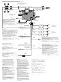
Connection example / Ejemplo de conexiónes / – ‰u„ˇ¤ /
RCA pin cord (not supplied)
Cable con clavijas RCA (no suministrado)
RCA ” ‚} ‰u¡]«D“ –a¡^
––¤ 'M„q•‰‰u¶•“
•
– ‡q‰ ¿ „„q•‰'˛¤ˇ¥˛ ATA ¡]‰ ¿ „ƒ ˚‡q„q¡^¥\fl fi ¡A
¥\†v⁄ ‰u“”––¤ ‰u¡]´¯ƒ ¡^«Kfl ¤ „ +12 V “‰‹y„q
¡C
•
• –z“”¤T¤fiƒb«Æ/ …‹`… ¡⁄Wƒ‡⁄”‚mFM/AM⁄ ‰ufi ¡A§Y‰—§
„q ˚⁄ ‰u––¤ ‰u¡}´¯ƒ ¡~'˛“ ˜ „q•‰¿Ø⁄J ‰u¡}‹ıƒ ¡~
‡s– ¤ †{ƒ‡“”⁄ ‰u…W £ „“”„q•‰” ⁄l⁄W
¡C
‚ † ⁄”fie¡A‰—‹¢
‚‚gP
¡C
•
¥» ⁄£fl ¤ˇ¥˛⁄£¤ª‡˘˜~„q‰c“”„q ˚⁄ ‰u
¡C
«O«ø O —“”‰u‚ ‡s– “k
• ‡s– ƒn¶ ƒ „q•‰¿Ø⁄J„q‰ufi ¡A§Y¤ˇ¤T¤fi o ˚ ´I⁄ı˘_ ˝´
ƒb„q•‰´_¶}ƒ ‚m¡A„q•‰⁄·˜~˜ ¤ „ O —„q‰u¥H«O«ø O —…˘
¡C
‡s– ·›`n „fi “”“‘•N¤˘¶
•
‡s– ·›`n „„q‰u⁄§«e¡A‰—¥ ˆ –…¥» „q•‰
¡C
•
‰—¤ˇ¥˛ 4 ¤ 8 … “ § ¡M¤ˆ¤ªƒ‡ AƒX¥» ¤ˇ¥˛“”„qfie¶q“”·›
`n „
¡C
§_«h•|•lˆa·›`n „
¡C
•
⁄£¥i§ ·›`n „” ⁄l‡s– ¤ ¤T¤fi'‡‰L
¡C
•
⁄£¥i‚ „ˇ¤ˆ`p·›`n „
¡C
•
‹ ` §K‹G» ¡Aƒp“G‚ ‚¸‚m¥‰” ⁄ ¤ ¥k›–'M¥“›–·›`n „“”⁄‰
¥˛›t ¡]
#
¡^ ‰u¡A‰—⁄¯¤ˇ¥˛–z¤fi⁄⁄ƒw‚¸“”⁄”‚m·›`n „
‰u
¡C
•
‰—⁄¯–N¥»‚¸‚m·›`n „ ‰u‹ ⁄‹‡s–
¡C
•
⁄£¥i‡s– ƒ‡•‰·›`n „¡]⁄”‚¸ƒ‡'æ⁄j „“ ¡^ƒ ¥» “”·›`n „
”⁄l
¡C
§_«h•|•lˆa·›`n „
¡C
‡o¤˙” ⁄l¥ufl ‡s– L•‰·›`n
„
¡C
Notas sobre cables de control y de fuente de
alimentación
• El cable de control de antena motorizada (azul)
suministra +12 V CC al activar el sintonizador o la
función ATA (Activación automática del
sintonizador).
• Si el automóvil dispone de una antena de FM/AM
incorporada en el cristal trasero/lateral, será
necesario conectar el cable de control de antena
motorizada (azul) o el cable auxiliar de entrada de
alimentación (rojo) al terminal de alimentación del
amplificador de antena existente. Para obtener
información detallada, consulte a su proveedor.
• Con esta unidad no podrá emplearse una antena
motorizada desprovista de caja de relé.
Conexión para protección de la memoria
Si conecta el cable de entrada de alimentación
amarillo, el circuito de la memoria siempre recibirá
alimentación, aunque ponga la llave de encendido en
la posición OFF.
Notas sobre la conexión de los altavoces
• Antes de conectar los altavoces, desconecte la
alimentación de la unidad.
• Utilice altavoces con una impedancia de 4 a 8
ohmios, y con la potencia admisible adecuada, ya
que de lo contrario podría dañarlos.
• No conecte los terminales del sistema de altavoces al
chasis del automóvil.
• No intente conectar los altavoces en paralelo.
• Para evitar fallos de funcionamiento, no utilice los
cables de altavoz incorporados instalados en el
automóvil si su unidad comparte un cable negativo
común (#) para los altavoces derecho e izquierdo.
• No conecte los cables de altavoz de la unidad entre
sí.
• No conecte altavoces activos (con amplificadores
incorporados) a los terminales de altavoces de la
unidad. Si lo hiciese, podría dañar tales altavoces.
Por lo tanto, cerciórese de conectar altavoces pasivos
a estos terminales.
Notes on the control and power supply leads
• The power aerial control lead (blue) supplies +12 V
DC when you turn on the tuner or when you
activate the ATA (Automatic Tuner Activation)
Function.
• When your car has a built-in FM/AM aerial in the
rear/side glass, it is necessary to connect the power
aerial control lead (blue) or the accessory power
input lead (red) to the power terminal of the
existing aerial booster. For details, consult your
dealer.
• A power aerial without relay box cannot be used
with this unit.
Memory hold connection
When the yellow power input lead is connected,
power will always be supplied to the memory circuit
even when the ignition key is turned off.
Notes on speaker connection
• Before connecting the speakers, turn the unit off.
• Use speakers with an impedance of 4 to 8 ohms, and
with adequate power handling capacities.
Otherwise, the speakers may be damaged.
• Do not connect the terminals of the speaker system
to the car chassis.
• Do not attempt to connect the speakers in parallel.
• To avoid malfunction, do not use the built-in
speaker wires installed in your car if its unit end
share a common negative (#) lead for the right and
left speakers.
• Do not connect the unit’s speaker cords to each
other.
• Do not connect any active speakers (with built-in
amplifiers) to the speaker terminals of the unit.
Doing so may damage the active speakers.
Therefore, be sure to connect passive speakers to
these terminals.
from car aerial
de la antena del automóvil
¤ ƒ ¤T¤fi⁄ ‰u
BUS cable (not supplied)
Cable BUS (no suministrado)
BUS ¡]¥ ‰u¡^„q˘l¡]«D“ –a¡^
Rotary commander (RM-X4S) (not supplied)
Mando rotativo (RM-X4S) (no suministrado)
– ´ ––¤ „ (RM-X4S) ¡]«D“ –a¡^
Blue/white striped
Azul con raya blanca
´¯ƒ¡¥ƒ–łfl
AMP REM
Max. supply current 0.3 A
Corriente máx. de alimentación de 0,3 A
‡ ⁄j¤ „q¶q 0.3 A
Fuse (10 A)
Fusible (10 A)
«O I •¡]10 A¡^
BUS IN
BUS
AUDIO IN
AUDIO
OUT FRONT
AUDIO
OUT REAR
4
Blue
Azul
´¯ƒ
Max. supply current 0.1 A
Corriente máx. de alimentación de 0,1 A
‡ ⁄j¤ „q¶q 0.1 A
ANT REM
Red
Rojo
‹ıƒ
Yellow
Amarillo
¶ƒ
Black
Negro
¶´ƒ
Green
Verde
”æƒ
Purple
Púrpura
ƒ
Grey
Gris
ƒ˙ƒ
White
Blanco
¥ƒ
to the +12 V power terminal which is energized in the accessory
position of the ignition key switch
• If there is no accessory position, connect to the +12 V power (battery)
terminal which is energized at all times.
• Be sure to connect the black earth lead to it first.
• When your car has a built-in FM/AM aerial in the rear/side glass, see
“Notes on the control and power supply leads.”
a un terminal de alimentación de +12 V que se energice en la posición
auxiliar de la llave de encendido
• Si no existe posición auxiliar, realice la conexión al terminal de
alimentación (batería) de +12 V que reciba energía
permanentemente.
• Asegúrese de conectar primero a este terminal el cable de puesta a
masa negro.
• Si el automóvil incorpora una antena de FM/AM en el cristal trasero/
lateral, consulte “Notas sobre cables de control y de fuente de
alimentación”.
ƒ ƒb´I⁄ı˘_ ˝“”»†§Uƒ ‚m⁄W‡q„q“” +12 V „q•‰” ⁄l
•
›Y¤Sƒ‡»†§Uƒ ‚m¡A«h‰—‡s– ƒ –‘fi ‡q„q“” +12 V „q•‰¡]„qƒ ¡^” ⁄l
¡C
•
¨‰—›”¥ –N¶´ƒ – ƒa‰u»P¤ ‡s–
¡C
•
–z¤T¤fi“”«Æ/ … ¡ƒp“G⁄”‚¸ƒ‡FM/AM⁄ ‰u¡A‰— ¤£¡§––¤ 'M„q•‰‰u¶•“ ¡¤
¡C
to the +12 V power terminal which is energized at all times
Be sure to connect the black earth lead to it first.
a un terminal de alimentación de +12 V que esté
permanentemente energizado
Asegúrese de conectar primero a este terminal el cable de puesta
a masa negro.
ƒ ‚g–‘‡q„q“” +12 V „q•‰” ⁄l
¨‰—›”¥ –N¶´ƒ – ƒa‰u– ⁄W¡C
to a metal point of the car
First connect the black earth lead, then connect the yellow and red
power input leads and orange/white striped illumination control lead.
a un punto metálico del automóvil
Primero conecte el cable de puesta a masa negro y, a continuación, los
cables de entrada de alimentación amarillo y rojo, así como el cable de
control de iluminación naranja con raya blanca.
ƒ ¤T¤fi“”“ ˜ ‡¡ƒ
›”¥ ‡s– ¶´ƒ – ƒa‰u¡AƒA‡s– ¶ ƒ 'M‹ıƒ “”„q•‰¿Ø⁄J ‰u¡A¥H⁄˛ ƒ/¥ ƒ –łfl
“”• 'œ––¤ ‰u¡C
To connect to AMP REMOTE IN of the optional power
amplifier.
This connection is only for amplifiers. Connecting any
other system may damage the unit.
Para conectar a AMP REMOTE IN del amplificador de
potencia opcional.
Esta conexión es sólo para amplificadores. La conexión
de cualquier otro sistema puede dañar la unidad.
‡s– ƒ ¿ `˚¥ ¥\†v'æ⁄j „“” AMP REMOTE IN¡]'æ⁄j „»»
––¿Ø⁄J¡^
¡C
¥»‡s– ¥u¥˛' 'æ⁄j „¡A‡s–¥ƒ¤¥Lˆ·†˛¥ifl •|•lˆa¥»
¡C
to the interface cable of a car telephone
al cable de interfaz de un teléfono para automóvil
ƒ ¤T¤fi„q‚ “”– ⁄f„q˘l
Sky blue
Azul celeste
⁄ ´¯ƒ
ATT
Orange/white striped
Naranja con raya blanca
ƒ¡¥ƒ–łfl
to a car’s illumination signal
Be sure to connect the black ground to it first.
a una señal de iluminación del automóvil
Asegúrese de conectar primero a este terminal el cable de puesta
a masa negro.
ƒ ¤T¤fi“”• 'œ«H‚„
¨‰—›”¥ –N¶´ƒ – ƒa‰u– ⁄W¡C
ILLUMINATION
to the power aerial control lead or power supply lead of aerial
booster amplifier
Notes
• It is not necessary to connect this lead if there is no power aerial
or aerial booster, or with a manually-operated telescopic aerial.
• When your car has a built-in FM/AM aerial in the rear/side glass,
see “Notes on the control and power supply leads.”
al cable de control de la antena motorizada, o al cable de fuente
de alimentación del amplificador de antena
Notas
• Si no se dispone de antena motorizada ni de amplificador de
antena, o se utiliza una antena telescópica accionada
manualmente, no será necesario conectar este cable.
• Si el automóvil incorpora una antena de recepción de FM/AM
en el cristal trasero/lateral, consulte “Notas sobre cables de
control y de fuente de alimentación”.
ƒ „q ˚⁄ ‰u––¤ ‰u'˛⁄ ‰u⁄ £'æ⁄j „“”„q•‰ ‰u
ø
•
ƒp“G¤T¤fi⁄W¤Sƒ‡„q ˚⁄ ‰u'˛⁄ ‰u⁄ £'æ⁄j „¡A'˛‹O¤T¤fi⁄W‚¸ƒ‡⁄ ˚ƒø
`Yƒ¡⁄ ‰ufi ¡A·N⁄£¥†‡s– ‡ofi ‰u
¡C
•
–z¤T¤fi“”«Æ/ … ¡ƒp“G⁄”‚¸ƒ‡ FM/AM ⁄ ‰ufi ¡A§Y‰— ‹ ¡§––¤ 'M„q•‰
‰u¶•“ ¡¤
¡C
Left
Izquierdo
¥“
Right
Derecho
¥k
Left
Izquierdo
¥“
Right
Derecho
¥k
Choke coil box
Caja de la bobina
“ ›•“ø‰u ؆
REMOTE IN
Front speakers
Altavoces delanteros
«e·›`n „
Rear speakers
Altavoces traseros
«Æ·›`n „
-
 1
1
-
 2
2
-
 3
3
-
 4
4


en otros idiomas
- English: Sony WX-C5000 Installation guide
Artículos relacionados
-
Sony WX-C55 Guía de instalación
-
Sony CDX-F5700 Guía de instalación
-
-
-
-
-
-
-
-