TPI YES-1524-1A Manual de usuario
- Categoría
- Calentadores espaciales
- Tipo
- Manual de usuario

Issue Date: 4-19-02 Rev. Date: 03/14 Rev. Level: 19 ECO1-6931 OIPM P/N 8997 Page 1 of 27
FOSTORIA INDUSTRIES
114 Roscoe Fitz Road
Gray, TN 37615
Phone: 800-495-4525
Fax: 419-435-0842
www.fostoriaindustries.com
FES - Series
Portable Electric Heaters
IMPORTANT SAFETY INFORMATION INSIDE
CONSIGNES DE SÉCURITÉ IMPORTANTES
À L'INTÉRIEUR
• Serious injury or death possible.
des blessures graves ou la mort • possible.
• Read, understand, and follow all safety
information and instructions in this manual
before using or servicing this product.
Lire, comprendre et suivre toutes les
consignes de sécurité et instructions de ce
manuel avant d'utiliser ou de réparer ce
produit.
• Retain these instructions for future
reference.
Conserver ces instructions pour référence
ultérieure.
CONTENTS
Specifications
Page 3
YES
Installation
Page 4
FES Assembly
Page 5
Wiring
Page
5,6,7,8,9,10,11
Operating
Page 12
Replacement
Parts
Page 13,14
Maintenance
Page 15
Limited
Warranty
Page 12
YES - Series
Suspended Electric Heaters
(FES-1524-3E shown)
A DIVISION OF
If you have questions about the
product you have purchased or would
like to leave us feedback please
contact us via our website
www.fostoriaindustries.com
or by calling 1-800-495-4525.

Issue Date: 4-19-02 Rev. Date: 03/14 Rev. Level: 19 ECO1-6931 OIPM P/N 8997 Page 2 of 27
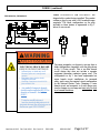
IMPORTANT INSTRUCTIONS
When using electrical appliances, basic precautions should always be followed to reduce the risk of fire,
electric shock, and injury to persons, including the following:
1. Read all instructions before using this heater.
2. CAUTION:
High temperatures. Keep cords and all other combustible material, such as furniture,
papers, clothes and curtains away from the heater. For safe and efficient operation,
keep an open space around heater of three feet in front and 12 inches at ends and rear.
ATTENTION: Les températures élevées. Gardez les cordons et tout autre matériau combustible,
tels que les meubles, papiers, vêtements et rideaux à l'extérieur de l'appareil
de chauffage. Pour un fonctionnement sûr et efficace, garder un espace ouvert
autour de chauffage de trois pieds à l'avant et 12 pouces aux extrémités et à l'arrière.
3. Extreme caution is necessary when any heater is used by or near children or invalids and whenever the
heater is left operating and unattended.
4. Do not operate any heater after it malfunctions, has been dropped or damaged in any manner. Return heater to
authorized service facility for examination, electrical or mechanical adjustment, or repair.
5. Do not use outdoors.
6. To disconnect heater, turn controls to off, and turn off power to heater circuit at main disconnect panel (or
operate internal disconnect switch if provided).
7. Do not insert or allow foreign objects to enter any ventilation or exhaust opening as this may cause an
electric chock or fire, or damage the heater.
8. To prevent a possible fire, do not block air intakes or exhaust in any manner.
9. A heater has hot and arcing or sparking parts inside. WARNING: Do not use it in area where gasoline, paint, or
flammable liquids are used or stored.
14. Use this heater only as described in this manual. Any other use not recommended by the manufacturer
may cause fire, electric shock, or injury to persons.
10. This heater may include an audible or visual alarm to warn that parts of the heater are getting excessively, hot
If the alarm sounds (or illuminates), immediately turn the heater off and inspect for any objects on or adjacent
to the heater that may have blocked the airflow or otherwise caused high temperatures to have occurred.
DO NOT OPERATE THE HEATER WITH THE ALARM SOUNDING (OR ILLUMINATING).
11. SAVE THESE INSTRUCTIONS

Issue Date: 4-19-02 Rev. Date: 03/14 Rev. Level: 19 ECO1-6931 OIPM P/N 8997 Page 3 of 27
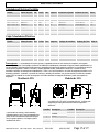
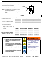
Description –
Fostoria portable and suspended electric heaters provide clean, quiet, odor-free, fan-forced heat. They are
designed to circulate room air continuously; gradually heating a confined space. The best results will be obtained when using these
heaters in smaller, insulated spaces. Features include a safety-yellow enclosure with front and rear safety screens; reliable stainless
steel finned heating elements; a high-limit temperature switch with automatic reset; an automatic thermostat control with fan-only
option; and a long-life motor and fan assembly with sealed bearings. The portable (FES) models come mounted on a two-wheeled
cart with wheels designed to be easily pushed or pulled over uneven surfaces.
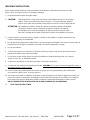
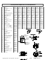
SPECIFICATIONS
Model
Part number
kW
Volts
PH
Amps
Fan Output
Heat Output
Dim B
YES-1024-1CA
08861510
10
240
1
42
800 CFM
34152 BTUH
36”
YES-1520-3A
08860810
15
208
3
41.5
800 CFM
51228 BTUH
36”
YES-1524-1A
08861810
15
240
1
62.5
800 CFM
51228 BTUH
38”
YES-1524-3E
08860910
15
240
3
36
800 CFM
51228 BTUH
36”
YES-1548-3E
08861010
15
480
3
18
800 CFM
51228 BTUH
36”
YES-1560-3A
08861110
15
600
3
14.4
800 CFM
51228 BTUH
36”
YES-3048-3A
08861210
30
480
3
36
1100 CFM
102455 BTUH
38”
YES-3060-3A
08861310
30
600
3
30
1100 CFM
102455 BTUH
38’
Model
Part number
kW
Volts
PH
Amps
Fan Output
Heat Output
Dim A
FES-0924-1C
08743302
9
240
1
37.5
800 CFM
30737 BTUH
21”
FES-1024-1CA
08860010
10
240
1
42
800 CFM
34152 BTUH
21”
FES-1520-3A
08860110
15
208
3
41.5
800 CFM
51228 BTUH
21”
FES-1524-1A
08860710
14
240
1
58.3
800 CFM
51228 BTUH
23”
FES-1524-3E
08860210
15
240
3
36
800 CFM
51228 BTUH
21”
FES-1548-3E
08860310
15
480
3
18
800 CFM
51228 BTUH
21”
FES-1560-3A
08860410
15
600
3
14.4
800 CFM
51228 BTUH
21”
FES-3048-3A
08860510
30
480
3
36
1100 CFM
102455 BTUH
23”
FES-3060-3A
08860610
30
600
3
30
1100 CFM
102455 BTUH
23”
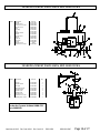
Portable Electric Heaters
Suspended Electric Heaters
27”
39”
FES Models
23”
23”
17.5”
YES Models
A
B
Quantity
Description
1
Bracket wall/ceiling
1
Hanger
2
Washer steel
2
Knob
2
Washer rubber
Quantity
Description
1
Rotating stop - Top
1
Nut stop ½ -13
1
Bolt ½-13 x 1-1/2
1
Nylon washer
2
Rotating stop – side
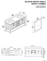
All Fostoria FES models come fully-assembled
except the handle is attached in a lowered shipping
position when shipped from the factory. Dimensions
above are for handle in operating position. See page
4 for final assembly of handle.
YES models are shipped with the following items. Check to make
certain all parts are at hand prior to beginning the installation.

Issue Date: 4-19-02 Rev. Date: 03/14 Rev. Level: 19 ECO1-6931 OIPM P/N 8997 Page 4 of 27
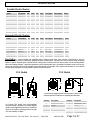
Tools required: (2) ¾” socket or box wrenches.
Parts required: the two screws required to secure
wall/ceiling bracket to a suitable surface are not
supplied with heater. You must use 5/16” bolts and
flat washers to mount this bracket.
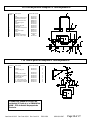
Hanger Assembly Detail
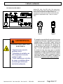
YES - SERIES INSTALLATION
HANGER
Step 1: Install (1) side rotating stop over
bolt and into curved slot (as shown at
right) on each side of heater.
Step 3: Secure wall/ceiling mounting bracket to appropriate
surface that will support a min. weight of 100lbs continuously.
NOTE: all mounting hardware to mount hanger to wall/ceiling
bracket is supplied with heater.
KNOB
ALL Fostoria YES models require some assembly. Four steps are required to complete the assembly and installation.
TOP of
Heater
Step 2: Assemble hanger to heater per hanger
assembly detail. No tools are required.
Ceiling Mount Option
Step 4: Assemble unit to mounting bracket following
instructions of chosen mounting option below.
Wall Mount Option #1
TOP ROTATING
STOP
TOP
of
Heater
FALLING OBJECTS HAZARD
FIRE HAZARD
CHUTES D'OBJETS LES RISQUES
RISQUE D'INCENDIE
Serious injury or death may occur.
Blessures graves ou la mort peuvent survenir.
Read and follow all safety information and
instructions in box below.
Lire et suivre toutes les consignes de
sécurité et les instructions dans la
boîte ci-
dessous.
• Mounting bracket supplied with YES models
MUST be used to support heater.
• Installer MUST be certain surface that
bracket is mounted to will support 100 lbs of
weight continuously.
• Rotating stops MUST be installed as shown
above.
• Do not mount heater upside down (See
nameplate label for “TOP” of heater.)
• The bottom of these units must be mounted at
least 6 ft. off the floor and the top 2 ft. from
the ceiling.
• Do not suspend ANY other equipment from
this bracket. One heater per bracket
Wall Mount Option #2
TOP
of
Heater

Issue Date: 4-19-02 Rev. Date: 03/14 Rev. Level: 19 ECO1-6931 OIPM P/N 8997 Page 5 of 27
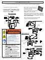
Tools Required: (2) 7/16” socket or box wrenches.
To position the handle at operating height:
Step 1
:
Remove and keep the hardware securing the
handle to the legs.
Step 2
:
Raise handle until holes align with the upper
holes in the legs.
Step 3
: Re-insert hardware as shown,
and fasten
securely.
FES – SERIES ASSEMBLY
Bolts
Washers
Washers
Nuts
To order cable kits
Phone: 1-800-495-4525
Model
Table 2
Unit Rating
Cable Size – Over
50ft. long
Max. Cable
Length (ft)
FES1520-3A
15kW, 208 Volt, 3-Ph
4/4
120
FES1524-1A
15kW, 240 Volt, 1-Ph
2/3
215
FES1524-3E
15kW, 240 Volt, 3-Ph
6/4
150
FES1548-3E
15kW, 480 Volt, 3-Ph
12/4
140
FES1560-3A
15kW, 600 Volt, 3-Ph
12/4
190
FES3048-3A
30kW, 480 Volt, 3-Ph
6/4
300
FES3060-3A
30kW, 600 Volt, 3-Ph
6/4
350
THE PROPER SIZE SO- type feeder cable MUST BE USED for the electrical hook-up of this heater. The proper cable size is shown
in the tables below (A.W.G./ # of conductors.) Table 1 is for cable 50ft.
in length or less. Table 2 is for cable longer than 50ft.
ELECTRICAL SHOCK HAZARD
FIRE HAZARD
RISQUE DE CHOC ÉLECTRIQUE
RISQUE D'INCENDIE
Serious injury or death may occur
Blessures graves ou la mort peuvent survenir.
Disconnect from electrical supply before installing
feeder cable to these heaters.
Couper l'alimentation électrique avant d'installer un
câble d'alimentation de ces appareils de chauffage.
Read and follow all safety information in box to
the left.
Lire et suivre toutes les consignes de sécurité
dans la boîte vers la
gauche.
• Feeder cable or cable kit assembly MUST BE
made by licensed electricians ONLY.
• Service panel or receptacle used to supply power
to these heaters MUST have a ground bus or
ground pole that is securely bonded to earth
ground.
• Connect green ground conductor on feeder cable
or cable kit to grounding lug on heaters.
• Comply with ALL local electrical codes and the
National Electric Code (NFPA70) when providing
electrical power to these heaters.
Model
Table 1
Unit Rating
Cable Size - Under
50ft. long
Cable
Kit Number
FES1520-3A
15kW, 208 Volt, 3-Ph
6/4
03164001
FES1524-1A
15kW, 240 Volt, 1-Ph
4/3
08805300
FES1524-3E
15kW, 240 Volt, 3-Ph
6/4
03164001
FES1548-3E
15kW, 480 Volt, 3-Ph
12/4
03164201
FES1560-3A
15kW, 600 Volt, 3-Ph
12/4
03164201
FES3048-3A
30kW, 480 Volt, 3-Ph
6/4
03164001
FES3060-3A
30kW, 600 Volt, 3-Ph
6/4
03164001
WIRING
A 25ft. cable kit can be purchased from the
factory. Refer to the kit part numbers in table at
right.
CABLE KITS INCLUDE:
• 25 feet of Type SO cable, with either 3-
conductors or 4-conductors, depending on
the heater requirements.

Issue Date: 4-19-02 Rev. Date: 03/14 Rev. Level: 19 ECO1-6931 OIPM P/N 8997 Page 6 of 27
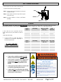
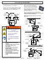
WIRING (continued)
FES-1024-1CA, FES-0924-1C
Models FES-1024-1CA and FES-0924-1C are
shipped with a cordset factory-installed. This cordset
contains a plug for use with a 50A household range
receptacle. The blade configuration on the plug
included on these heaters is represented in fig. 1
below (4-wire circuit).
fig. 2
fig. 1
The range receptacle you choose to use may have a
blade configuration compatible with the plug shown
in fig. 2 (3-wire circuit). This is an older branch
circuit design that does not include a separate
equipment grounding conductor (green wire). The
configuration in fig. 1 has been implemented on
newer branch circuit
installations for increased
safety, and is now the required circuit configuration
by the National Electric Code. Changing a 3-wire
branch circuit and receptacle to 4-wire design may
involve changes to your range and must only be done
by a licensed electrician.
ELECTRICAL SHOCK HAZARD
RISQUE DE CHOC ÉLECTRIQUE
• Serious injury or death may occur.
Blessures graves ou la mort peuvent
survenir.
• Plug heater into a 4-wire circuit
receptacle rated 50A.
Chauffage Branchez un circuit à 4 fils
prise nominale 50A.
• Any and all changes to branch
circuits and receptacles MUST be
done by a licensed electrician
ONLY.
Toutes les modifications et
tous les circuits de dérivation et de
récipients doivent être effectués par un
électricien agréé SEULEMENT.

Issue Date: 4-19-02 Rev. Date: 03/14 Rev. Level: 19 ECO1-6931 OIPM P/N 8997 Page 7 of 27
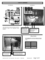
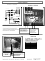
WIRING (continued)
TERMINAL
BLOCK
YES-1524-1A
YES-1524-1A
Attach circuit conductors at
these lugs. Refer to label
shown for phase
identification
Ground lug is located
directly below fuse as
shown in upper left
corner. Securely attach
green wire to this lug.
Attach feeder cable or cable kit to heater as shown in
photograph at right for the single-
phase models
indicated.
3-Phase Models
Attach feeder cable or cable kit to heater as shown in
the photograph at left for the following 3-phase
models.
FES-1520-3A
YES-1520-3A
FES-1524-3E
YES-1524-3E
FES-1548-3E
YES-1548-3E
FES-1560-3A
YES-1560-3A
FES-3048-3A
YES-3048-3A
FES-3060-3A
YES-3060-3A
Ground Lug
Securely attach green
wire to this lug.
Attach circuit conductors to the lugs
on the contactor. Refer to label
shown for phase identification.

Issue Date: 4-19-02 Rev. Date: 03/14 Rev. Level: 19 ECO1-6931 OIPM P/N 8997 Page 8 of 27
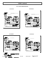
YES-1520-3A
YES-1524-3E
CABLE NOT INCLUDED
CABLE NOT INCLUDED
WIRING (continued)
YES 3- PHASE WIRING DIAGRAMS
YES-1548-3E
YES-1560-3A
CABLE NOT INCLUDED
CABLE NOT INCLUDED
MAXIMUM OVERCURRENT PROTECTION 45 AMPS.
USE COPPER WIRE ONLY
MAXIMUM OVERCURRENT PROTECTION 55 AMPS.
USE COPPER WIRE ONLY
MAXIMUM OVERCURRENT PROTECTION 25 AMPS.
USE COPPER WIRE ONLY
MAXIMUM OVERCURRENT PROTECTION 20 AMPS.
USE COPPER WIRE ONLY

Issue Date: 4-19-02 Rev. Date: 03/14 Rev. Level: 19 ECO1-6931 OIPM P/N 8997 Page 9 of 27
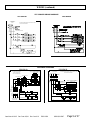
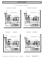
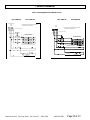
FES WIRING DIAGRAMS
FES-1524-1A FES-1524-3E
L1
L2
L3
L4 T4
T3
T2
T1
CONTACTOR
COIL
FAN MOTOR
FAN
6 4
CONTACTOR COIL
1
3
FLANGED
INLET
RECEPT.
LOCKING
CONNECTOR
X Y
G
X Y
G
MAXIMUM OVERCURRENT
PROTECTION 80 AMPS,
USE COPPER WIRE ONLY
GND
L1
L2
THERMOSTAT
NON-CYCLING
OVERTEMP SWITCH
THERMOSTAT CYCLING
L4
L3
240 VOLTS 60HZ
1-PHASE 15KW
240V / 2500W ELEMENTS
TYPICAL (6)
TERMINAL
BLOCK
FUSE FLNR-40 250V
L2
L1
MAXIMUM OVERCURRENT PROTECTION 45 AMPS,
USE COPPER WIRE ONLY
GROUND LUG
CONTACTOR COIL
L1 L2 L3
NON-CYCLING
FAN MOTOR
FAN
CONTACTOR
COIL
OVERTEMP SWITCH
1
3
6
4
CYCLING
L3 T3
L2 T2
L1 T1
L1
L2
L2
L1
L1
L3
240 VOLTS 60HZ
3-PHASE 15KW
240V / 2500W ELEMENTS
TYPICAL (6)
FLANGED
INLET
RECEPT.
LOCKING
CONNECTOR
Y
G
X
W
GND
YES-3048-3A
YES-3060-3A
WIRING (continued)
YES 3-PHASE WIRING DIAGRAMS
CABLE NOT INCLUDED
CABLE NOT INCLUDED
MAXIMUM OVERCURRENT PROTECTION 55 AMPS.
USE COPPER WIRE ONLY.
480 VOLTS 60 HZ
3-PHASE
30 KW

Issue Date: 4-19-02 Rev. Date: 03/14 Rev. Level: 19 ECO1-6931 OIPM P/N 8997 Page 10 of 27
FES-1520-3A FES-1548-3E
OVERTEMP SWITCH
1
3
6
4
CYCLING
L3 T3
L2 T2
L1 T1
L1
L2
L2
L1
L1
L3
208 VOLTS 60HZ
3-PHASE 15KW
240V / 2500W ELEMENTS
TYPICAL (6)
FLANGED
INLET
RECEPT.
LOCKING
CONNECTOR
Y
G
W
X
GND
MAXIMUM OVERCURRENT PROTECTION 25 AMPS,
USE COPPER WIRE ONLY
GROUND LUG
NON-CYCLING
FAN MOTOR
OVERTEMP SWITCH
CYCLING
L1
L2
L2
L1
L1
L3
480 VOLTS 60HZ
3-PHASE 15KW
240V / 2500W ELEMENTS
TYPICAL (6)
CONTACTOR COIL
L3 T3
L2 T2
L1 T1
6
4
FAN
CONTACTOR
COIL
1
3
L1 L2 L3
FLANGED
INLET
RECEPT.
LOCKING
CONNECTOR
Y
G
Z
X
GND
MAXIMUM OVERCURRENT PROTECTION 55 AMPS,
USE COPPER WIRE ONLY
GROUND LUG
CONTACTOR COIL
L1 L2 L3
NON-CYCLING
FAN MOTOR
FAN
CONTACTOR
COIL
FES-1560-3A FES-3048-3A
MAXIMUM OVERCURRENT PROTECTION 45 AMPS,
USE COPPER WIRE ONLY
GROUND LUG
NON-CYCLING
FAN MOTOR
OVERTEMP SWITCH
CYCLING
L2
L1
L1
480 VOLTS 60HZ
3-PHASE 30KW
240V / 2500W ELEMENTS
TYPICAL (12)
CONTACTOR COIL
L1 T1
L2 T2
L3 T3
FAN
6
4
CONTACTOR
COIL
1
3
GROUND LUG
L1
L2
L3
L1 L2 L3
FLANGED
INLET
RECEPT.
LOCKING
CONNECTOR
Y
G
Z
X
GND
MAXIMUM OVERCURRENT PROTECTION 20 AMPS,
USE COPPER WIRE ONLY
GROUND LUG
NON-CYCLING
FAN MOTOR
OVERTEMP SWITCH
CYCLING
L1
L2
L2
L1
L1
L3
600 VOLTS 60HZ
3-PHASE 15KW
300V / 2500W ELEMENTS
TYPICAL (6)
CONTACTOR COIL
L3 T3
L2 T2
L1 T1
6
4
FAN
CONTACTOR
COIL
1
3
L1 L2 L3
FLANGED
INLET
RECEPT.
LOCKING
CONNECTOR
Y
G
Z
X
GND
WIRING (continued)

Issue Date: 4-19-02 Rev. Date: 03/14 Rev. Level: 19 ECO1-6931 OIPM P/N 8997 Page 11 of 27
FES-3060-3A
MAXIMUM OVERCURRENT PROTECTION 40 AMPS,
USE COPPER WIRE ONLY
GROUND LUG
NON-CYCLING
FAN MOTOR
OVERTEMP SWITCH
CYCLING
L2
L1
L1
600 VOLTS 60HZ
3-PHASE 30KW
300V / 2500W ELEMENTS
TYPICAL (12)
CONTACTOR COIL
L1 T1
L2 T2
L3 T3
FAN
6
4
CONTACTOR
COIL
1
3
GROUND LUG
L1
L2
L3
L1 L2 L3
FLANGED
INLET
RECEPT.
LOCKING
CONNECTOR
Y
G
Z
X
GND
WIRING (continued)

Issue Date: 4-19-02 Rev. Date: 03/14 Rev. Level: 19 ECO1-6931 OIPM P/N 8997 Page 12 of 27
OPERATING INSTRUCTIONS
FIRE HAZARD, BURN HAZARD,
EXPLOSION HAZARD
RISQUE D'INCENDIE, RISQUE DE
BURN, RISQUE D'EXPLOSION
• Serious injury or death
may occur.
Blessures graves ou la
mort peuvent survenir.
• Read and follow all safety
information in box below.
Lire et suivre toutes les consignes de
sécurité ci-dessous.
• Do not use outdoors or where flammable gases or
liquids are stored.
• Do not use as a residential comfort heater.
•
Keep portable heater 3ft. minimum from all
combustible materials at all times.
• Do not modify heater in any way.
• Do not provide power to heater when unit is near
standing water.
• Only use handle to move heater.
• Do not touch heater housing while in use.
• Do not allow feeder cable to contact combustible
materials.
• Always purge heat from unit after use. Operate
at “fan only” setting for 3 minutes.
• Extreme caution is necessary when any heater is
used or near children or
invalids and whenever
the heater is left operating and unattended.
• Do not insert or allow foreign objects to enter
any ventilation or exhaust opening as this may
cause an electric shock or fire, or damage the
heater.
Fostoria FES and YES series heaters are designed
to circulate room air across its heating elements to
gradually increase room temperature. The best
performance results will be obtained when using
these heaters in smaller, confined spaces with low
ceilings.
Operation of these heaters is accomplished via the
use of a multi-
function thermostat (refer to
diagram below).
You have the option to use the fan only*, or the
fan and heating elements together. Position the
knob pointer in the “fan-only” area to circulate
room air with no heating. Move the pointer into
the “heat” area to energize the heating elements
and set the thermostat. Maximum heating is
obtained with knob turned fully clockwise**.
Both fan and elements are off when the knob is
turned fully counterclockwise.
Allow the fan to operate for a minimum of 3
minutes when you are done using the heater to
purge heat from unit.
*The thermostat has a preset range of 40˚F to
100˚F. If the ambient room temperature is
below 40˚F, there will be no “fan only”
function as the thermostat is always calling for
heat.
**Setting the thermostat to high heat versus
low heat does not make the unit operate at a
higher temperature. It simply raises the
temperature necessary to satisfy the
thermostat. The unit will run longer to try to
satisfy a higher thermostat setting.
HEATER
OFF
L
N
A
F
O
N
Y
LOW
HEAT
HIGH
HEAT
Note: ALL FES/YES models are equipped with
an internal over temperature limit designed to
protect your heater if a restricted airflow
condition occurs. This limit device will
completely shutdown the heating elements if the
temperature limit is reached. The limit will
automatically reset when the unit cools.

Issue Date: 4-19-02 Rev. Date: 03/14 Rev. Level: 19 ECO1-6931 OIPM P/N 8997 Page 13 of 27
5
43
44
23
22
34
10,12,28
45
38
FES REPLACEMENT PARTS LIST& EXPLODED VIEWS
17
Ref
No.
Description
1024-1CA
0924-1C
1520-3A
1524-3E
1548-3E
1560-3A
3048-3A
3060-3A
1
Motor
08482001 (1)
08482001 (1)
08482001 (1)
08482002 (1)
08482003 (1)
08482004 (1)
08482005 (1)
2
Bolt carriage ½-13 x 2-3/4
32137-001 (2)
32137-001 (2)
32137-001 (2)
32137-001 (2)
32137-001 (2)
32137-001 (2)
32137-001 (2)
3
Rotating stop
32127-001 (2)
32127-001 (2)
32127-001 (2)
32127-001 (2)
32137-001 (2)
32137-001 (2)
32137-001 (2)
4
Thermostat
02470300 (1)
02470300 (1)
02470300 (1)
02470300 (1)
02470300 (1)
02470300 (1)
02470300 (1)
5
Washer Reducing (not
shown)
N/A N/A N/A 5256 (2) 5256 (2) N/A N/A
6
Knob thermostat
02470500 (1)
02470500 (1)
02470500 (1)
02470500 (1)
02470500 (1)
02470500 (1)
02470500 (1)
7
Strap
32103-001 (1)
32103-001 (1)
32103-001 (1)
32103-001 (1)
32103-001 (1)
32103-001 (1)
32103-001 (1)
8
Shroud
32136-101 (1)
32136-101 (1)
32136-101 (1)
32136-101 (1)
32136-101 (1)
32126-101 (1)
32126-101 (1)
9
Motor mount bracket
32122-002 (1)
32122-002 (1)
32122-002 (1)
32122-002 (1)
32122-002 (1)
32122-001 (1)
32122-001 (1)
10
Screw 10-32x 5/16 SEMS
32110-001 (8)
32110-001(12)
32110-001(12)
32110-001(12)
32110-001(12)
32110-001(24)
32110-001(24)
11
Mount motor end
32121-001 (2)
32121-001(2)
32121-001 (2)
32121-001 (2)
32121-001 (2)
32121-001 (2)
32121-001 (2)
12
Washer 9/16
42469-001 (8)
42469-001(12)
42469-001(12)
42469-001(12)
42469-001(12)
42469-001(24)
42469-001(24)
13
Nut hex ¼-20
1042 (4)
1042 (4)
1042 (4)
1042 (4)
1042 (4)
1042 (4)
1042 (4)
14
Washer ¼
1036 (8)
1036 (8)
1036 (8)
1036 (8)
1036 (8)
1036 (8)
1036 (8)
15
Grill
08480621 (2)
08480621 (2)
08480621 (2)
08480621 (2)
08480621 (2)
08480621 (2)
08480621 (2)
16
Washer
43625-004 (4)
43625-004 (4)
43625-004 (4)
43625-004 (4)
43625-004 (4)
43625-004 (4)
43625-004 (4)
17
Screw 8-18 x ½
5081
5081
5081
5081
5081
5081
5081
18
Contactor
58027-038 (1)
58027-038
(1)
58027-038
(1)
58027-035
(1)
08480403 (1)
58027-035
(1)
08480403 (1)
19
Cordset – not shown
32147-001 (1)
------
------
------
------
------
------
20
Nut ½-13
28952-001 (2)
28956-001 (2)
28956-001 (2)
28956-001 (2)
28956-001 (2)
28956-001 (2)
28956-001 (2)
21
Screw ¼-20 x ¾
3494156 (4)
43893-009 (4)
43893-009 (4)
43893-009 (4)
43893-009 (4)
43893-009 (4)
43893-009 (4)
22
Over temperature switch
03183900 (1)
03183900 (1)
03183900 (1)
03183900 (1)
03183900 (1)
41041-001 (1)
41041-001 (1)
23
Ground Lug
41254-001 (1)
41254-001 (1)
41254-001 (1)
41254-001 (1)
41254-001 (1)
41254-001 (1)
41254-001 (1)
24
Connector
32108-002 (1)
32108-002 (1)
32108-002 (1)
32108-001 (1)
32108-001 (1)
32108-002 (1)
32108-002 (1)
25
Baffle – not shown
32130-001 (1)
32130-001 (1)
32130-001 (1)
32130-001 (1)
32130-001 (1)
32130-001 (1)
32130-001 (1)
26
Bussbar – not shown
32115-001 (4)
32115-001 (8)
32115-001 (8)
32115-001 (5)
32115-001 (5)
32115-001(10)
32115-001(10)
27
Element inner 1024-C1A
08481401 (2)
08481403 (3)
08481401 (3)
08481401 (3)
08481405 (3)
08481401 (6)
08481405 (6)
0924-C1
91005-021 (2)
28
Element outer 1024-C1A
08481402 (2)
08481404 (3)
08481402 (3)
08481402 (3)
08481406 (3)
08481402 (6)
08481406 (6)
0924-C1
91005-022 (2)
29
30
35
36
37
Blade fan – not shown
Cover
Flanged Inlet Cover
Flanged Inlet Recept.
Locking Connector
08422300 (1)
32125-101 (1)
N/A
N/A
N/A
08422300 (1)
32125-101 (1)
58769-102 (1)
58758-003 (1)
58759-003 (1)
08422300 (1)
32125-101 (1)
58769-102 (1)
58758-003 (1)
58759-003 (1)
08422300 (1)
32125-101 (1)
58769-102 (1)
58758-001 (1)
58759-001 (1)
08422300 (1)
32125-101 (1)
58769-102 (1)
58758-002 (1)
58759-002 (1)
08422300 (1)
32125-101 (1)
58769-102 (1)
58758-004 (1)
58759-004 (1)
08422300 (1)
32125-101 (1)
58769-102 (1)
58758-002 (1)
58759-002 (1)
Ref
No.
Description
1524-1A
1
Motor
08482001 (1)
2
Bolt carriage ½-13 x 2-3/4
32137-001 (2)
3
Rotating stop
32127-001 (2)
4
Thermostat
02470300 (1)
5
Washer reducing (not
shown)
N/A
6
Knob thermostat
02470500 (1)
7
Strap
32103-001 (1)
8
Shroud
32126-101 (1)
9
Motor mount bracket
32122-001 (1)
10
Screw 10-32x 5/16 SEMS
32110-001 (12)
11
Mount motor end
32121-001 (2)
12
Washer 9/16
42469-001(12)
13
Nut hex ¼-20
1042 (4)
14
Washer ¼
1036 (10)
15
Grill
08480621 (2)
16
Washer
43625-004 (4)
17
Screw 8-18 x ½
5081
18
Contactor
58027-053 (1)
19
20
Nut ½-13
28956-001 (2)
21
Screw ¼-20 x ¾
43893-009 (4)
22
Over temperature switch
0318900 (1)
23
Ground Lug
41254-001 (1)
24
Connector
32108-002 (1)
25
Baffle-not shown
32130-001 (1)
26
Bussbar – not shown
32115-001 (8)
27
Element inner
08481401 (3)
28
Element outer
08481402 (3)
29
Blade fan – not shown
08422300 (1)
30
Cover
32125-101 (1)
31
Bracket fuse block
32128-001 (1)
32
Fuse block
50836-020 (2)
33
34
Fuse type FLNR-40 250V
Terminal block
41280-003 (4)
51243-002 (1)

Issue Date: 4-19-02 Rev. Date: 03/14 Rev. Level: 19 ECO1-6931 OIPM P/N 8997 Page 14 of 27
To convert an FES unit to a YES unit
order the Fostoria kit Model WMK-FES
p/n 04804102.
FES REPLACEMENT PARTS LIST& EXPLODED VIEWS
YES REPLACEMENT PARTS LIST& EXPLODED VIEWS
6
Ref No.
Description
Part No.
1
Handle
32117-001
2
Washer flat ¼
43625-005
3
Screw ¼-20 x 2-3/4
43893-008
4
Nut stop ¼-20
43894-001
5
Axle
58649-001
6
Cap plug
32109-001
7
Leg
32117-002
8
Washer rubber
32123-001
9
Spacer
32120-001
10
Washer flat ½
32142-001
11
Wheel
58648-001
12
Push nut
54877-001
13
Bar Knob
32141-001
14
Spacer
32106-001
15
Washer lock ¼
1036
16
Screw ¼-20 x 1-3/4
32111-001
Ref No.
Description
Part No.
Qty.
1
Hanger
32145-003
1
2
Washer rubber
32123-001
2
3
4
Bar knob
32141-001
2
5
Mounting bracket
57074-102
1
6
Washer fender
32142-001
4
7
Washer nylon
32143-001
1
8
Rotating stop
32144-001
1
9
Nut stop ½-13
43923-001
1
10
Screw ½-13 x 1-1/2
28953-004
1
11
Rotating Stop – Side
32146-001
2

Issue Date: 4-19-02 Rev. Date: 03/14 Rev. Level: 19 ECO1-6931 OIPM P/N 8997 Page 15 of 27
ELECTRICAL SHOCK HAZARD
RISQUE DE CHOC ÉLECTRIQUE
• Serious injury or death may
occur.
Blessures graves ou la mort.
• Disconnect from electrical
supply before servicing or
cleaning these heaters.
Déconnectez-électrique
fournir avant l'entretien ou
le nettoyage de ces
appareils de chauffage.
• Do not operate without grills
and access covers fastened in
place.
•
Ne pas utiliser sans grilles et
couvercles d'accès fixées en place.
Other than periodic cleaning of the exterior, no maintenance
is required for these heaters.
• Do not hose these units down.
• Remove dust and dirt from inside heater with
compressed air.
• Do not operate these heaters without the grills or the
wiring compartment cover in place.
• Replace or repair feeder cable or cord set if visible
damage is observed.
• Motor bearings are permanently lubricated.
The warranty herein set forth is in lieu of all other warranties expressed or
implied.
Fostoria Industries, Inc. of Gray, TN 37615, warrants its products to the owner
against defects in material and workmanship for a twelve (12) month period
under normal use and service following date of manufacture or installation when
proof of such is provided to sell
er.
This Warranty requires that the owner, or his agent, install the equipment in
accordance with the National Electrical Code, any other applicable heating or
electrical codes and the manufacturer’s installation instructions. It further requires
that he
perform reasonable and necessary maintenance on the unit. The
company is not liable for abuse or misuse of product as may be finally
determined by the company.
The obligation of Fostoria Industries, Inc. under the terms of this warranty, shall be to
supply a new part, repair of defective part, or a refund, at the company’s option with no
cost to owner for the new or repaired part. Such parts are to be returned to the factory, or
such other location as the company may designate. This warranty does not obligate
Fostoria Industries, Inc.
to bear the cost of labor in replacing any assembly, unit or
component part thereof, nor does the company assume any liability for secondary
charges, expenses for installing or removal, or any other consequential losses. The
company’s maximum liability shall not in any case exceed the list price for the product
claimed to be defective.
The warranty shall not apply to any product or parts of products which have been repaired
or altered outside of Seller’s factory in any manner. Warranty is void on products
that have
been determined to have been subjected to misuse, negligence or accident or which have
been used in a manner contrary to Seller’s instructions.
FOSTORIA INDUSTRIES, INC. – 114 Roscoe Fitz Road - Gray, TN 37615 - (419) 435-9201
LIMITED WARRANTY
MAINTENANCE

Issue Date: 4-19-02 Rev. Date: 03/14 Rev. Level: 19 ECO1-6931 OIPM P/N 8997 Page 16 of 27
FOSTORIA INDUSTRIES, INC.
114 Roscoe Fitz Road
Gray, TN 37615
Phone: 800-495-4525
Fax: 419-435-0842
www.fostoriaindustries.com
UNA DIVISIÓN DE
FES - Serie
Calentadores Eléctrico
Portátiles
IMPORTANTE INOCUIDAD
INFORMACIÓN DENTRO
• Lesión seria o posible de muerte.
• Lea, comprenda, y siga toda
información de seguridad e
instrucciones en este manual antes
de usar o atienda este producto.
• Conserve estas instrucciones para
futuras consultas.
Contenido
Especificaciones
Página 14
Instalación de YES
Página 15
Asamblea de FES
Página 16
Cableado
Página
16,17,18,19,20
Operar
Página 21
Partes de reemplazo
Página 22,23
Mantenimiento
Página 24
Garantía limitada
Página 24
YES - Serie
Calentadores Eléctrico
Suspendido
(FES - 1524 - 3E mostrado)
Fabricamos productos de calidad desde 1917
ADVERTENCIA
Si usted tiene las preguntas acerca
del producto usted ha comprado o
querría salirnos reacción por favor
nos contacta vía nuestro sitio web
www.fostoriaindustries.com o
llamando 1-800-495-4525.

Issue Date: 4-19-02 Rev. Date: 03/14 Rev. Level: 19 ECO1-6931 OIPM P/N 8997 Page 17 of 27
Descripción –
Los calentadores de Fostoria, portátil y suspendido proveen el calor forzado por ventilador. Son limpieza,
silencioso, y olor gratis. Son diseñados circular aire de habitación constantemente; calentando un espacio limitado gradualmente. Los
mejores resultados serán obtenidos Cuándo usan estos calentadores en espacios más pequeños y aislados. Las características incluyen
un cercamiento seguridad - amarillo con frente y traseras seguridad biombo; Elementos de calefacción con aletas de acero
inoxidable confiables; un interruptor de temperatura alto - límite, con el revés automático; un control de termostato automático con la
alternativa ventilador - solamente; y un motor de vida largo y asamblea de ventilador con cojinete cerrado. El modelo de calentador
portátil (FES) es instalado en un carro de dos giraron con ruedas diseñadas ser empujado fácilmente o jalado sobre superficies
irregulares.
ESPECIFICACIONES
Modelo
Número de parte
KW
Voltios
Fase
Amperios
Producto de ventelator
Producto de Calor
Mida B
YES - 1024 -1CA
08861510
10
240
1
42
800 CFM
34152 BTUH
36 "
YES - 1520 - 3A
08860810
15
208
3
41.5
800 CFM
51228 BTUH
36 "
YES - 1524 - 1A
08861810
15
240
1
62.5
800 CFM
51228 BTUH
38 "
YES - 1524 - 3E
08860910
15
240
3
36
800 CFM
51228 BTUH
36 "
YES - 1548 - 3E
08861010
15
480
3
18
800 CFM
51228 BTUH
36 "
YES - 1560 - 3A
08861110
15
600
3
14.4
800 CFM
51228 BTUH
36 "
YES - 3048 - 3A
08861210
30
480
3
36
1100 CFM
102455 BTUH
38 "
YES - 3060 - 3A
08861310
30
600
3
30
1100 CFM
102455 BTUH
38 ’
Modelo
Número de parte
KW
Voltios
Fase
Amperios
Producto de soplador
Producto de Calor
Mida A
FES - 1024 -1CA
08744302
9
240
1
37.5
800 CFM
30737 BTUH
21 "
FES - 1024 -1CA
08860010
10
240
1
42
800 CFM
34152 BTUH
21 "
FES - 1520 - 3A
08860110
15
208
3
41.5
800 CFM
51228 BTUH
21 "
FES - 1524 - 1A
08860710
15
240
1
62.5
800 CFM
51228 BTUH
23 "
FES - 1524 - 3E
08860210
15
240
3
36
800 CFM
51228 BTUH
21 "
FES - 1548 - 3E
08860310
15
480
3
18
800 CFM
51228 BTUH
21 "
FES - 1560 - 3A
08860410
15
600
3
14.4
800 CFM
51228 BTUH
21 "
FES - 3048 - 3A
08860510
30
480
3
36
1100 CFM
102455 BTUH
23 "
FES - 3060 - 3A
08860610
30
600
3
30
1100 CFM
102455 BTUH
23 "
Calentadores Eléctricos Portátiles
Colgó Calentadores Eléctricos
27”
39”
Modelos de FES
23”
23”
17.5”
Modelos de YES
A
B
Cantidad
Descripción
1
Pared / techo de
corchete
1
Percha
2
Acero de arandela
2
Pomo
2
Goma de arandela
Cantidad
Descripción
1
Tope rotativa - Alto
1
La parada de nuez ½ x 13
1
½ - 13 x 1-1/2 de - perno
1
Arandela de nilón
2
Tope rotativa – de lado
Todos modelos de Fostoria, vienen montados
totalmente menos el asa. El asa está montada en un
puesto de envío.Dimensiones más arriba son para
asa en el puesto operativo. Vea Página 4 para la
asamblea final de asa.
Los modelos de YES incluir lo siguiente artículos. Verifique para
asegurarse que todas partes están cerca antes de empezar la
instalación.

Issue Date: 4-19-02 Rev. Date: 03/14 Rev. Level: 19 ECO1-6931 OIPM P/N 8997 Page 18 of 27
Paso 2: monte percha to calentador por el
detalle de la asamblea de percha. Ninguna
herramienta es requeridas.
Herramientas requerían: (2) ¾" Llave inglesa
Requerir: los dos tornillos requeridos instalar el corchete
de pared / techo. No ser proporcionado con calentador.
Usted debe usar pernos 5/16 " y arandela bemol .
Percha
Paso 1: instale (1) girando parada sobre
perno y en solt curvado (como mostrado en
el derecho) sobre cada costado de calentador.
Paso 3:
Corchete de pared / techo de instalación para la
superficie apropiada que respaldará un peso de mimimum de 100
libra. Nota: los pernos son suministrados.
Pomo
ELECCION DE MONTURA DE TECHO
# 1 DE OPCIÓN DE MONTURA DE PARED
Arandela
de acero
Arandela
de goma
Tope
rotativa
Perno
Arandela
de acero
Arandela
de nilón
Tope
rotativa
Alto de
calentador
Arandela
de acero
Nuez
Arandela
de acero
Arandela de nilón
Tope rotativa
Ápice de
calentador
Nuez
Arandela
de acero
Perno
Todos modelos de YES de Fostoria requieren un poco de ensamblaje. Cuatro pasos son requeridos terminar la asamblea y la instalación.
# 2 DE OPCIÓN DE MONTURA DE PARED
YES - INSTALACIÓN DE SERIE
Arandela
de acero
Ápice de
calentador
Perno
Arandela de nilón
Arandela
de acero
Nuez
Paso 4: Montar unidad para corchete siga a instrucciones
elegidos abajo.
ADVERTENCIA
PELIGRO DE OBJETOS
CAYENDO
PELIGRO DE INCENDIO
• Perjuicio serio o muerte
podrían ocurrir.
• Lea y siga toda información
de seguridad y instrucciones
abajo
• El corchete enviado con calentador debe
serlo usar.
• La superficie a la que esa repisa es instalada
debe respaldar 100 libra de peso
ininterrumpido.
• Tope rotativa debe ser instalado como
mostrado arriba.
• No instale calentador al revés. Mire la
etiqueta para la punta de calentador.
• Calentador de montura al menos 6 s pie de
piso y 2 pies de techo.
• No cuelgue cualquier otro equipo de este
corchete. Un calentador por el corchete
máximo.

Issue Date: 4-19-02 Rev. Date: 03/14 Rev. Level: 19 ECO1-6931 OIPM P/N 8997 Page 19 of 27
ADVERTENCIA
Herramientas requerían: (2) 7/16 " llaves inglesas de caja.
Para colocar el asa en la altura operativa:
Paso 1: Se quitar y guarde el pertrechos que fija el asa a las
piernas.
Paso 2: Se levantar el asa hasta que los agujeros se alinean
con el alto agujeros en las piernas.
Paso 3:
Vuelva a introducir pernos como mostrado, y abroche
afianzar.
FES - asamblea de serie
Pernos
Arandela
Arandela
Nuez
Para pedir producto de cable
Teléfono: 1-800-495 - 4525
Modelo
Table 2
Clasificación de unidad
Tamaño de cable –
Mas de 50 pies
Max. Cable
Longitud (pies)
FES1520-3A
15kW, 208 voltio, 3 - Ph
4/4
120
FES1524-A
15kW, 240 voltio, 1 - Ph
2/3
215
FES1524-3E
15kW, 240 voltio, 3 - Ph
6/4
150
FES1548-3E
15kW, 480 voltio, 3 - Ph
12/4
140
FES1560-3A
15kW, 600 voltio, 3 - Ph
12/4
190
FES3048-3A
30kW, 480 voltio, 3 - Ph
6/4
300
FES3060-3A
30kW, 600 voltio, 3 - Ph
6/4
350
El alimentador cable de - tipo SO debe ser usado para la conexión eléctrica de este calentador. El tamaño de cable correcto es
mostrado en las mesas abajo (A.W.G./ # de alambres.) El Cuadro 1 es para el cable 50 pies de longitud o menos. El Cuadro 2 e
s para
el cable más largo q
ue 50 pies.
PELIGRO DE CONMOCIÓN
ELÉCTRICO
PELIGRO DE INCENDIO
• Perjuicio serio o muerte podrían
ocurrir.
• Desconécte el suministro eléctrico
antes de instalar el cable de
alimentador a estos calentadores.
• Leer y siga información de
seguridad todos a la izquierda.
• Alimentador cable o ensamblaje de producto de cable
deben ser hecho por electricistas SOLAMENTE
autorizado.
• Panel eléctrico o tomas de corriente que son use
proporcionar el poder a éstos calentadores deben
tener una unidad terminal de tierra o varilla de tierra
que son adheridas a tierra.
• Conecte a director de tierra verde sobre alimentador
cable o producto cable a terminal sobre calentadores.
• Obedezca todos códigos eléctricos locales y el código
eléctrico nacional (NFPA70) cuando proveer el poder
eléctrico a estos calentadores.
Cableado
Un producto de cable 25 pies puede ser
comprado de la fábrica. Mire los números
de producto en la tabla en el derecho.
CABLE PRODUCTO INCLUYEN:
• 25 pies de cable de Type SO, con
cualquier 3 - directores o 4 directores,
depender de los requisitos de
calentador.
Modelo
Table 1
Clasificación de unidad
Tamaño de cable
– Bajo 50 pies
Cable Número
de paquete
FES1520-3A
15kW, 208 voltio, 3 - Ph
6/4
03164001
FES1524-A
15kW, 240 voltio, 1 - Ph
4/3
08805300
FES1524-3E
15kW, 240 voltio, 3 - Ph
6/4
03164001
FES1548-3E
15kW, 480 voltio, 3 - Ph
12/4
03164201
FES1560-3A
15kW, 600 voltio, 3 - Ph
12/4
03164201
FES3048-3A
30kW, 480 voltio, 3 - Ph
6/4
03164001
FES3060-3A
30kW, 600 voltio, 3 - Ph
6/4
03164001

Issue Date: 4-19-02 Rev. Date: 03/14 Rev. Level: 19 ECO1-6931 OIPM P/N 8997 Page 20 of 27
Cableado (continuado)
FES-1024-1CA, FES-0924-1C
Figura 2
Figura 1
El reseptacle que usted decide usar podría tener una
configuración de brizna compatible con el enchufe
indicado en higo. 2 (el circuito 3 cable). Esto es un
diseño de circuito de rama más viejo que no incluye
a un director de restricción de conductor de
conexion a teirra (cable verde). La configuración en
higo. 1 ha sido implementado en las instalaciones
de circuito de rama más nuevas para la inocuidad
incrementar y es ahora la configuración de circuito
requerida por el código eléctrico nacional. Cambiar
un circuito de rama 3 cable y recipiente al diseño 4
cable puede involucrar los cambio a receptacle ser
hecho por un electricista dado licencia solamente.
PELIGRO DECONMOCIÓN
ELÉCTRICO
• Perjuicio serio o muerte
podrían ocurrir.
• Calentador de enchufe a un
50A recipiente de circuito
evaluar 4 cable.
• Todos cambios para circuitos
de rama y recipientes deben
ser hecho por un licencia
electricista solamente.
ADVERTENCIA
Modelos FES - 1024 - 1CA y FES - 0924 - 1CA enviar con un
cordon instalado fábrica. Este cordon contiene un enchufe para
el uso con uno 50 receptaculo de amperio electrico. La
configuración de brizna sobre el enchufe incluída sobre estos
calentadores es representada en higo. 1 abajo (el circuito 4
cable).

Issue Date: 4-19-02 Rev. Date: 03/14 Rev. Level: 19 ECO1-6931 OIPM P/N 8997 Page 21 of 27
Cableado (continuado)
FES-1524-1A YES-1524-1A
FES-1524-1A YES-1524-1A
Directores de circuito de
attach en estas ubicaciones.
Consulte la etiqueta
mostrada para la
identificación de fase.
El tierra está ubicado
directamente debajo del
fusible mostrado en la
esquina izquierda alto. Fije
cable verde a este tierra.
Conecte alimentador cable o producto de cable a
calentador como mostrado en fotografia en el derecho,
para los modelos solo - fase demostrados.
Modelos 3 fase
Fije alimentador cable o producto de cable a
calentador tan mostrado en la fotografía en la
izquierda para lo siguiente modelos 3 fase.
FES-1520-3A
YES-1520-3A
FES-1524-3E
YES-1524-3E
FES-1548-3E
YES-1548-3E
FES-1560-3A
YES-1560-3A
FES-3048-3A
YES-3048-3A
FES-3060-3A
YES-3060-3A
Tierra conductor
Fije cable verde a esta
oreja tierra.
Fije a directores de circuito a las
tierra sobre el contactor. Consulte la
etiqueta mostrada para la
identificación de fase.
TERMINAL
BLOCK
FUSIBLE FLNR-40 250V
BLOQUE
TERMINALE
TERMOSTATO
MOTOR DE VENTILADOR
TERMOSTATO
ROLLO DE CONTACTOR
NO CICLISMO
MÁXIMO SOBRE LOS AMPERIOS DE PROTECCIÓN 80. USE CABLE DE COBRE SOLAMENTE
CICLISMO
TIERRA
OREJA
SOBRE LA
TEMPERATURA
INTERRUPTOR
240 VOLTIES
1-FASE
15KW
240V/2500W ELEMENTOS
ESCRIBA A MAQUINA 6

Issue Date: 4-19-02 Rev. Date: 03/14 Rev. Level: 19 ECO1-6931 OIPM P/N 8997 Page 22 of 27
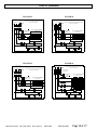
CABLE NO INCLUIDO
MOTOR DE VENTILADOR
ROLLO DE CONTACTOR
NO CICLISMO
MÁXIMO SOBRE LOS AMPERIOS DE PROTECCIÓN 45.
USE CABLE DE COBRE SOLAMENTE
CICLISMO
TIERRA CONEXION
SOBRE LA
TEMPERARURA
INTERRUPTOR
240 VOLTIES 60 HZ
3-FASE
15KW
ROLLO DE CONTACTOR
240V/2500W ELEMENTOS
ESCRIBA A MAQUINA 6
CABLE NO INCLUIDO
MOTOR DE VENTILADOR
ROLLO DE CONTACTOR
NO CICLISMO
MÁXIMO SOBRE LOS AMPERIOS DE PROTECCIÓN 55.
USE CABLE DE COBRE SOLAMENTE
CICLISMO
TIERRA CONEXION
SOBRE LA
TEMPERARURA
INTERRUPTOR
208 VOLTIES 60 HZ
3-FASE
15KW
ROLLO DE CONTACTOR
208V/2500W ELEMENTOS
ESCRIBA A MAQUINA 6
FES-1520-3A YES-1520-3A
Cableado (continuado)
FES & YES Diagramas de cableado 3 fase
CABLE NO INCLUIDO
MOTOR DE VENTILADOR
ROLLO DE CONTACTOR
NO CICLISMO
MÁXIMO SOBRE LOS AMPERIOS DE PROTECCIÓN 25.
USE CABLE DE COBRE SOLAMENTE
CICLISMO
TIERRA CONEXION
SOBRE LA
TEMPERARURA
INTERRUPTOR
480 VOLTIES 60 HZ
3-FASE
15KW
ROLLO DE CONTACTOR
480V/2500W ELEMENTOS
ESCRIBA A MAQUINA 6
CABLE NO INCLUIDO
MOTOR DE VENTILADOR
ROLLO DE CONTACTOR
NO CICLISMO
MÁXIMO SOBRE LOS AMPERIOS DE PROTECCIÓN 20.
USE CABLE DE COBRE SOLAMENTE
CICLISMO
TIERRA CONEXION
SOBRE LA
TEMPERARURA
INTERRUPTOR
600 VOLTIES 60 HZ
3-FASE
15KW
ROLLO DE CONTACTOR
300V/2500W ELEMENTOS
ESCRIBA A MAQUINA 6
FES-1548-3E YES-1548-3E
FES-1560-3A YES-1560-3A
FES-1524-3E YES-1524-3E

Issue Date: 4-19-02 Rev. Date: 03/14 Rev. Level: 19 ECO1-6931 OIPM P/N 8997 Page 23 of 27
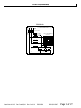
FES-3048-3A YES-3048-3A
FES-3060-3A YES-3060-3A
Cableado (continuado)
FES & YES Diagramas de cableado 3 fase
CABLE NO INCLUIDO
NO CICLISMO
MÁXIMO SOBRE LOS AMPERIOS DE PROTECCIÓN 55.
USE CABLE DE COBRE SOLAMENTE
CICLISMO
TIERRA CONEXION
SOBRELA LA
TEMPERATURA
INTERRUPTOR
480 VOLTIES 60 HZ
3-FASE
30KW
240V/2500W ELEMENTOS
ESCRIBA A MAQUINA 12
CABLE NO INCLUIDO
ROLLO DE CONTACTOR
NO CICLISMO
MÁXIMO SOBRE LOS AMPERIOS DE PROTECCIÓN 40.
USE CABLE DE COBRE SOLAMENTE
CICLISMO
TIERRA CONEXION
SOBRELA LA
TEMTERATURA
INTERRUPTOR
600 VOLTIES 60 HZ
3-FASE
30KW
ROLLO DE CONTACTOR
300V/2500W ELEMENTOS
ESCRIBA A MAQUINA 12
MOTORDE VENTILADOR

Issue Date: 4-19-02 Rev. Date: 03/14 Rev. Level: 19 ECO1-6931 OIPM P/N 8997 Page 24 of 27
EL PELIGRO DE FUEGO
EL PELIGRO DE EXPLOSIÓN
PELIGRO DE BURN
• Perjuicio serio o muerte
podrían ocurrir.
• Lea y siga el buzón de
entrada de información de
seguridad todos abajo.
Operar las instrucciones
• Nunca uso fuera o donde los gases
inflamables o líquidos son guardados.
• Nunca use como un consuelo residencial
calentador.
• Guarde calentador portátil 3 ft. mínimo
de todos materiales combustibles siempre.
• Nunca modifique calentador de alguna
manera.
• Nunca suministre el poder a calentador
cuando la unidad está cerca del agua
parada.
• Solamente use asa para cambiar de lugar
calentador.
• Nunca contacto vivienda de calentador
mientras en uso.
• Nunca permita que el alimentador cable
haga contacto con materiales
combustibles.
• Purgue el calor de unidad después del uso
siempre. Opere ventilador solamente
durante 3 minutos.
Nota: Todos modelos de FES / YES están
equipados con un límite de temper
atura de
interior over diseñado proteger su calentador si
una condición de corriente de aire restringida
ocurre. Este dispositivo de límite cesacion de
trabajo los elementos de calefacción totalmente
si el límite de temperatura es llegado. El límite se
reinicia cuando la unidad se enfría
automáticamente.
ADVERTENCIA
Fostoria FES y YES calentadores de serie son
diseñados hacer circular aire de habitación al otro lado
de sus elementos de calefacción para incrementar la
temperatura de habitación gradualmente. Los mejores
resultados de rendimien
to serán obtenidos cuando
usan estos calentadores en espacios más pequeños y
limitados con techos bajos.
La operación de estos calentadores está consumada vía
el uso de un termostato multi- función (enviar la
diagrama abajo).
Usted tiene
la alternativa de usar el ventilador
solamente*, o el ventilador y los elementos de
calefacción juntos. Coloque el puntero de pomo en la
área "fan only" ( ventilador solamente) de hacer
circular aire de habitación sin calefacción. Cambie de
lugar el puntero en la área de "Calor" de dar energía a
los elementos de calefacción y prepare el termostato.
La calefacción máxima es obtenida con pomo girado
completamente en sentido de las agujas del reloj**.
El ventilador y los elementos son apagados cuando el
pomo es girado completamente en sentido contrario a
las agujas del reloj.
El ventilador debe operar durante minimum de 3
minutos cuando usted es termino para purgarse
calor de unidad.
*El termostato tiene un fijó la gama de 40°F a
100°F. Si la temperatura ambiente del ambiente es
abajo 40°F, no habrá “ventilador sólo” funciona
como el termostato siempre llama para el calor.
**La colocación que el termostato para calentar
alto contra el calor bajo no hace el operar de la
unidad en una temperatura más alta. Levanta
simplemente la temperatura necesaria para
satisfacer el termostato. La unidad correrá más
largo tratar de satisfacer una colocación más alta
de termostato.
HEATER
OFF
L
N
A
F
O
N
Y
LOW
HEAT
HIGH
HEAT
Calor
minimo
Calor
alto
Calentador
apagado

Issue Date: 4-19-02 Rev. Date: 03/14 Rev. Level: 19 ECO1-6931 OIPM P/N 8997 Page 25 of 27
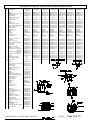
5
43
44
23
22
34
10,12,28
45
38
Lista de partes de reemplazo de FES &vistas esquemáticas
TOPA ROTATIVA
PARRILLA ANEXO
TERMOSTATO
VEA
TERMOSTATO
DETALLE
VEA TOPA
ROTATIVA
DETALLE
VEA EL
DETALLE DE
ANEXO DE LA
PARRILLA
RefNo.
Descripcion
1024-1CA
1520-3A
1524-3E
1548-3E
1560-3A
3048-3A
3060-3A
1
Motor
32129-001 (1)
32129-001 (1)
32129-001 (1)
32129-002 (1)
32129-003 (1)
32129-004 (1)
32129-005 (1)
2
Carruaje de perno ½-13 x 2-3/4
32137-001 (2)
32137-001 (2)
32137-001 (2)
32137-001 (2)
32137-001 (2)
32137-001 (2)
32137-001 (2)
3
Topa rotativa
32127-001 (2)
32127-001 (2)
32127-001 (2)
32127-001 (2)
32127-001 (2)
32127-001 (2)
32127-001 (2)
4
Termostato
32101-001 (1)
32101-001 (1)
32101-001 (1)
32101-001 (1)
32101-001 (1)
32101-001 (1)
32101-001 (1)
5
Arandela - no mostrado
------
------
------
5256 (2)
5256 (2)
------
------
6
Termostato de pomo
32102-001 (1)
32102-001 (1)
32102-001 (1)
32102-001 (1)
32102-001 (1)
32102-001 (1)
32102-001 (1)
7
Correa
32103-001 (1)
32103-001 (1)
32103-001 (1)
32103-001 (1)
32103-001 (1)
32103-001 (1)
32103-001 (1)
8
Mortaja
32136-101 (1)
32136-101 (1)
32136-101 (1)
32136-101 (1)
32136-101 (1)
32136-101 (1)
32136-101 (1)
9
Corchete de montura de motor
32122-002 (1)
32122-002 (1)
32122-002 (1)
32122-002 (1)
32122-002 (1)
32122-001 (1)
32122-001(1)
10
SEMS de 10 - 32x 5/16 de tornillo
32110-001 (8)
32110-001 (12)
32110-001(12)
32110-001(12)
32110-001(12)
32110-001 (24)
32110-001(24)
11
Final de montura de motor
32121-001 (2)
32121-001 (2)
32121-001 (2)
32121-001 (2)
32121-001 (2)
32121-001 (2)
32121-001 (2)
12
Arandela 9/16
42469-001 (8)
42469-001 (12)
42469-001 (12)
42469-001(12)
42469-001(12)
42469-001(24)
42469-001(24)
13
Nuez ¼ - 20 hexadecimal
1042 (4)
1042 (4)
1042 (4)
1042 (4)
1042 (4)
1042 (4)
1042 (4)
14
Arandela ¼
1036 (8)
1036 (8)
1036 (8)
1036 (8)
1036 (8)
1036 (8)
1036 (8)
15
Parrilla
58647-001 (2)
58647-001 (2)
58647-001 (2)
58647-001 (2)
58647-001 (2)
58647-001 (2)
58647-001 (2)
16
Arandela
43625-004 (4)
43625-004 (4)
43625-004 (4)
43625-004 (4)
43625-004 (4)
43625-004 (4)
43625-004 (4)
17
8-18 de tornillo x ½
5081
5081
5081
5081
5081
5081
5081
18
Contactor
32124-003 (1)
32124-003 (1)
32124-001 (1)
32124-002 (1)
32124-004 (1)
32124-002 (1)
32124-004 (1)
19
Cable y enchufe - no mostrar
32147-001 (1)
------
------
------
------
------
------
20
½ - 13 de nuez
28956-001 (2)
28956-001 (2)
28956-001 (2)
28956-001 (2)
28956-001 (2)
28956-001 (2)
28956-001 (2)
21
¾ de x de ¼ - 20 de tornillo
43893-009 (4)
43893-009 (4)
43893-009 (4)
43893-009 (4)
43893-009 (4)
43893-009 (4)
43893-009 (4)
22
Límite alto
32112-001 (1)
32112-001 (1)
32112-001 (1)
32112-001 (1)
32112-001 (1)
41041-001 (1)
41041-001 (1)
23
Oreja de suelo
41254-001 (1)
41254-001 (1)
41254-001 (1)
41254-001 (1)
41254-001 (1)
41254-001 (1)
41254-001 (1)
24
Conector
32108-002 (1)
32108-002 (1)
32108-002 (1)
32108-001 (1)
32108-001 (1)
32108-002 (1)
32108-002 (1)
25
Baffle – no mostrado
32130-001 (1)
32130-001 (1)
32130-001 (1)
32130-001 (1)
32130-001 (1)
32130-001 (1)
32130-001 (1)
26
Bussbar - no mostrar
32115-001 (4)
32115-001 (8)
32115-001 (8)
32115-001 (5)
32115-001 (5)
32115-001(10)
32115-001(10)
27
Elemento interior 1024-1CA
91005-013 (2)
91005-015 (3)
91005-013 (3)
91005-013 (3)
91005-017(3)
91005-013 (6)
91005-017 (6)
0924-1C
91005-021 (2)
28
Elemento exterior 1024-1CA
91005-014 (2)
91005-016 (3)
91005-014 (3)
91005-014 (3)
91005-018 (3)
91005-014 (6)
91005-018 (6)
0924-1C
91005-022 (2)
29
30
Admirador de hoja - no mostrado
Tapa
32116-001 (1)
32125-101 (1)
32116-001 (1)
32125-101 (1)
32116-001 (1)
32125-101 (1)
32116-001 (1)
32125-101 (1)
32116-001 (1)
32125-101 (1)
32116-001 (1)
32125-101 (1)
32116-001 (1)
32125-101 (1)
RefNo.
Descripcion
1524-1A
1
Motor
08482001(1)
2
Carruaje de perno ½-13 x 2-3/4
32137001(2)
3
Topa rotativa
32127001(2)
4
Termostato
02470300(1)
5
Arandela - no mostrado
-----
6
Termostato de pomo
02470500(1)
7
Correa
32103001(1)
8
Mortaja
32126101(1)
9
Corchete de montura de motor
32122001(1)
10
SEMS de 10 - 32x 5/16 de tornillo
32110001(12)
11
Final de montura de motor
32121001(2)
12
Arandela 9/16
42469001(12)
13
Nuez ¼ - 20 hexadecimal
1042 (4)
14
Arandela ¼
1036 (10)
15
Parrilla
08480621 (2)
16
Arandela
43625004 (4)
17
8-18 de tornillo x ½
5081
18
Contactor
08480406 (1)
19
20
½ - 13 de nuez
28956001 (2)
21
¾ de x de ¼ - 20 de tornillo
43893009 (4)
22
Límite alto
03183900 (1)
23
Oreja de suelo
41254001 (1)
24
conector
32108002 (1)
25
Baffle – no mostrado
32130001 (1)
26
Bussbar - no mostrar
32115001 (8)
27
Elemento interior
08481401 (3)
28
Elemento exterior
08481402 (3)
29
Admirador de hoja - no mostrado
08422300 (1)
30
Tapa
32125101 (1)
31
Bloque de fusible de corchete
32128001 (1)
32
Bloque de fusible
50836020 (2)
33
34
250V de FLNR - 40 de tipo de
fusible
Bloque final
41280003 (4)
51243002 (1)

Issue Date: 4-19-02 Rev. Date: 03/14 Rev. Level: 19 ECO1-6931 OIPM P/N 8997 Page 26 of 27
Cambiar una unidad de FES por una
unidad de YES pida el p / n 04804102 de
WMK - FES de modelo de paquete de
Fostoria.
FES Lista de partes de reemplazo & vistas esquemáticas
YES Lista de partes de reemplazo & vistas esquemáticas
Referencia
Numero
Descripción
Número de la pieza.
1
Asa
32117-001
2
Arandela Parte plana ¼
43625-005
3
Tornillo ¼-20 x 2-3/4
43893-008
4
Parada de nuez ¼-20
43894-001
5
Eje
58649-001
6
Enchufe de gorra
32109-001
7
Pierna
32117-002
8
Arandela de goma
32123-001
9
Separador
32120-001
10
Arandela Parte plana ½
43625-004
11
Rueda
58648-001
12
Nuez de empujón
54877-001
13
Pomo
32141-001
14
Separador
32106-001
15
Arandela Cerradura ¼
1036
16
Tornillo ¼-20 x 1-3/4
32111-001
Referencia
Numero
Descripción
Número de la pieza.
Cantidad
1
Percha
32145-003
1
2
Arandela de goma
32123-001
2
3
4
Pomo
32141-001
2
5
Corchete en aumento
57074-102
1
6
Guardabarros arandela
32142-001
4
7
Arandela de nilon
32143-001
1
8
Topa rotativa
32144-001
1
9
½ - 13 de alto de nuez
43923-001
1
10
½ - 13 x 1-1/2 de tornillo
28953-004
1
11
Topa rotativa– Costado
32146-001
2

Issue Date: 4-19-02 Rev. Date: 03/14 Rev. Level: 19 ECO1-6931 OIPM P/N 8997 Page 27 of 27
PELIGRO DE CONMOCIÓN
ELÉCTRICO
• Perjuicio serio o muerte
podrían ocurrir.
• Desconécte del suministro
eléctrico antes de atender o
limpie estos calentadores.
• Nunca opere sin parrillas y
tapas de acceso abrochadas en
su lugar.
Aparte de periódico limpiando del exterior, ningún
mantenimiento es requerido para estos calentadores.
• Nunca riegue estas unidades.
• Quite la suciedad desde el interior de calentador con
aire comprimido.
• Nunca opere estos calentadores sin las parrillas o el
compartimento de cableado la cobertura a término en
su lugar.
• Reemplace o repare alimentador cable o cordon si
daño visible es observado.
• Los cojinetes de motor son lubricados
permanentemente.
FOSTORIA INDUSTRIES, INC. – 114 Roscoe Fitz Road - Gray, TN 37615 - (419) 435-9201
Garantía limitada
Mantenimiento
ADVERTENCIA
La obligación de Fostoria Industries, Inc., de conformidad con las estipulaciones de esta
garantía, será suministrar una pieza nueva, reparar una pieza defectuosa, o remitir un
reembolso, todas estas opciones a la sola y total discreción de la compañía, sin cargo al
propietario, por la pieza nueva o reparación, según sea el caso. La pieza defectuosa debe
devolverse a la fábrica o a cualquier otra parte, según lo indique la compañía. Esta
garantía no obliga a Fostoria Industries, Inc. a cubrir el costo de la mano de obra para
reemplazar ensambles, unidades o componentes, ni la compañía asume ninguna
responsabilidad de cargos o gastos secundarios por concepto de la instalación o
desmontaje, ni de ninguna pérdida derivada. La máxima responsabilidad de la compañía
en ningún caso excederá el precio de lista del producto presentado como defectuoso.
La garantía no se aplica a ningún producto o pieza integrantes de un producto que haya
sido reparada o alterada fuera de la fábrica en ninguna forma. La garantía se anula con
respecto a todos aquellos productos que, a juicio de la compañía, hayan sido sujetos a
abuso, negligencia o accidentes, o hayan sido empleados en una forma contraria a
la
indicada en las instrucciones del fabricante.
La garantía descrita en este documento está en vigencia en lugar de cualquier
otra posible garantía, ya sea expresa o i
mplícita.
Fostoria Industries, Inc. of Gray, TN 37615, garantiza sus productos al
comprador contra cualquier defecto en los materiales y mano de obra durante un
período de doce (12) meses en uso y servicio normal a partir de la fecha de
fabricación o de i
nstalación si se suministra prueba de la misma al vendedor.
Esta garantía requiere que el propietario, o un agente del mismo, instale el
equipo de conformidad con el Reglamento Nacional de Instalaciones Eléctricas,
con cualquier otro reglamento de electri
cidad o calefacción que corresponda, y
con las instrucciones de instalación del fabricante. Asimismo, la garantía
requiere que se proporcione mantenimiento a la unidad, según sea necesario y
razonable. La compañía no es responsable del abuso y uso indebido
a que se
sujete la unidad, según lo determine en forma definitiva la compañía.
-
 1
1
-
 2
2
-
 3
3
-
 4
4
-
 5
5
-
 6
6
-
 7
7
-
 8
8
-
 9
9
-
 10
10
-
 11
11
-
 12
12
-
 13
13
-
 14
14
-
 15
15
-
 16
16
-
 17
17
-
 18
18
-
 19
19
-
 20
20
-
 21
21
-
 22
22
-
 23
23
-
 24
24
-
 25
25
-
 26
26
-
 27
27


TPI YES-1524-1A Manual de usuario
- Categoría
- Calentadores espaciales
- Tipo
- Manual de usuario
en otros idiomas
- English: TPI YES-1524-1A User manual
Otros documentos
-
 Style Selections MERCER-60W-COMBO Dimensions Guide
-
Marley QWD Series Instrucciones de operación
-
-
Carrier 52C Manual de usuario
-
 Marley Engineered Environmental Electric Heated Air Curtain Manual de usuario
-
Marley Engineered Products K series Manual de usuario
-
GE GE40T10BAM El manual del propietario
-
GE GE40T08BAM01 El manual del propietario
-
Empire SR-18T-3 El manual del propietario
-
Friedrich PDH15R5SG Installation & Operation Manual

