Makita XWL01PT Manual de usuario
- Categoría
- Herramientas eléctricas
- Tipo
- Manual de usuario
Este manual también es adecuado para

INSTRUCTION MANUAL
MANUAL DE INSTRUCCIONES
Cordless Portable Cut-off
Tronzadora Portátil Inalámbrica
XWL01
IMPORTANT: Read Before Using.
IMPORTANTE: Lea antes de usar.

2 ENGLISH
ENGLISH (Original instructions)
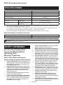
SPECIFICATIONS
Model: XWL01
Wheel diameter 355 mm (14″)
Hole diameter 25.4 mm (1″)
Max. wheel thickness 3 mm (1/8″)
No load speed (RPM) 3,800 /min
Rated voltage D.C. 36 V
Dimensions
(L x W x H)
With safety guard other than
European type
537 mm x 280 mm x 640 mm
(21-1/8″ x 11″ x 25-1/4″)
Net weight With safety guard other than
European type
15.6 - 16.3 kg (34.5 - 35.9 lbs)
•
Due to our continuing program of research and development, the specications herein are subject to change without notice.
• Specications may differ from country to country.
• The weight may differ depending on the attachment(s), including the battery cartridge. The lightest and heavi-
est combination, according to EPTA-Procedure 01/2014, are shown in the table.
• The shape and weight vary depending on the specications which differ country to country.
Applicable battery cartridge and charger
Battery cartridge
BL1815N / BL1820B / BL1830 / BL1830B / BL1840B / BL1850B / BL1860B
Charger DC18RC / DC18RD / DC18RE / DC18SD / DC18SE / DC18SF
•
Some of the battery cartridges and chargers listed above may not be available depending on your region of residence.
WARNING: Only use the battery cartridges and chargers listed above. Use of any other battery cartridges
and chargers may cause injury and/or re.
SAFETY WARNINGS
For Your Own Safety, Read
Instruction Manual Before
Operating Tool.
Wear Eye Protection.
Save it for future reference.
General safety precautions (For all tools)
1. KNOW YOUR POWER TOOL. Read the owner's
manual carefully. Learn the tool's applications
and limitations, as well as the specic poten-
tial hazards peculiar to it.
2.
KEEP GUARDS IN PLACE and in working order.
3. REMOVE ADJUSTING KEYS AND WRENCHES.
Form habit of checking to see that keys and
adjusting wrenches are removed from tool
before turning it on.
4. KEEP WORK AREA CLEAN. Cluttered areas
and benches invite accidents.
5. DO NOT USE IN DANGEROUS ENVIRONMENT.
Do not use power tools in damp or wet loca-
tions, or expose them to rain. Keep work area
well lighted. Do not use tool in presence of
ammable liquids or gases.
6. KEEP CHILDREN AWAY. All visitors should be
kept safe distance from work area.
7. MAKE WORKSHOP KID PROOF with padlocks,
master switches, or by removing starter keys.
8. DO NOT FORCE TOOL. It will do the job better
and safer at the rate for which it was designed.
9. USE RIGHT TOOL. Do not force tool or attach-
ment to do a job for which it was not designed.
10. WEAR PROPER APPAREL. Do not wear loose
clothing, gloves, neckties, rings, bracelets, or
other jewelry which may get caught in moving
parts. Nonslip footwear is recommended. Wear
protective hair covering to contain long hair.
11. ALWAYS USE SAFETY GLASSES. Also use
face or dust mask if cutting operation is dusty.
Everyday eyeglasses only have impact resis-
tant lenses, they are NOT safety glasses.
12. SECURE WORK. Use clamps or a vise to hold
work when practical. It's safer than using your
hand and it frees both hands to operate tool.
13. DO NOT OVERREACH. Keep proper footing
and balance at all times.
14. MAINTAIN TOOLS WITH CARE. Keep tools
sharp and clean for best and safest perfor-
mance. Follow instructions for lubricating and
changing accessories.
15. DISCONNECT BATTERY FROM TOOL before
servicing; when changing accessories such as
blades, bits, cutters, and the like.

3 ENGLISH
16. REDUCE THE RISK OF UNINTENTIONAL
STARTING. Make sure switch is in off position
before inserting battery.
17. USE RECOMMENDED ACCESSORIES. Consult
the owner's manual for recommended acces-
sories. The use of improper accessories may
cause risk of injury to persons.
18. NEVER STAND ON TOOL. Serious injury could
occur if the tool is tipped or if the cutting tool
is unintentionally contacted.
19. CHECK DAMAGED PARTS. Before further use
of the tool, a guard or other part that is dam-
aged should be carefully checked to determine
that it will operate properly and perform its
intended function - check for alignment of
moving parts, binding of moving parts, break-
age of parts, mounting, and any other condi-
tions that may affect its operation. A guard or
other part that is damaged should be properly
repaired or replaced.
20. DIRECTION OF FEED. Feed work into a blade
or cutter against the direction of rotation of the
blade or cutter only.
21. NEVER LEAVE TOOL RUNNING UNATTENDED.
TURN POWER OFF. Do not leave tool until it
comes to a complete stop.
22. REPLACEMENT PARTS. When servicing, use
only identical replacement parts.
Battery tool use and care
1. Ensure the switch is in the off position before
inserting battery cartridge. Inserting the battery
cartridge into power tools that have the switch on
invites accidents.
2. Recharge only with the charger specied by
the manufacturer. A charger that is suitable for
one type of battery cartridge may create a risk of
re when used with another battery cartridge.
3. Use power tools only with specically desig-
nated battery cartridges. Use of any other bat-
tery cartridges may create a risk of injury and re.
4. When battery cartridge is not in use, keep it
away from other metal objects like paper clips,
coins, keys, nails, screws, or other small metal
objects that can make a connection from one
terminal to another. Shorting the battery termi-
nals together may cause burns or a re.
5.
Under abusive conditions, liquid may be ejected
from the battery; avoid contact. If contact acci-
dentally occurs, ush with water. If liquid con-
tacts eyes, additionally seek medical help. Liquid
ejected from the battery may cause irritation or burns.
6.
Disconnect battery cartridge from tool or place
the switch in the locked or off position before
making any adjustments, changing accessories,
or storing the tool. Such preventive safety mea-
sures reduce the risk of starting the tool accidentally.
7. Have your power tool serviced by a qualied
repair person using only identical replacement
parts. This will ensure that the safety of the power
tool is maintained.
8. Do not use a battery pack or tool that is dam-
aged or modied. Damaged or modied batteries
may exhibit unpredictable behaviour resulting in
re, explosion or risk of injury.
9. Do not expose a battery pack or tool to re or
excessive temperature. Exposure to re or tem-
perature above 130 °C may cause explosion.
10. Follow all charging instructions and do not
charge the battery pack or tool outside the
temperature range specied in the instruc-
tions. Charging improperly or at temperatures
outside the specied range may damage the
battery and increase the risk of re.
Specic safety rules
DO NOT let comfort or familiarity with product
(gained from repeated use) replace strict adherence
to portable cut-off safety rules. If you use this tool
unsafely or incorrectly, you can suffer serious per-
sonal injury.
1. Wear hearing protection during extended
period of operation.
2. Use only wheels having a maximum operat-
ing speed at least as high as "No Load RPM"
marked on the tool’s nameplate. Use only
berglass-reinforced cut-off wheels.
3. Check the cut-off wheel carefully for cracks or
damage before operation. Replace cracked or
damaged wheel immediately. Run the tool (with
guard) at no load for about a minute, holding
tool away from others. If wheel is awed, it will
likely separate during this test.
4. Secure the cut-off wheel carefully.
5. Use only anges specied for this tool.
6. Be careful not to damage the spindle, anges
(especially the installing surface) or bolt.
Damage to these parts could result in wheel
breakage.
7. Do not operate the tool without guards in
place. Check the wheel guard for proper clos-
ing before each use. Do not operate the tool if
wheel guard does not move freely and close
instantly. Never clamp or tie the wheel guard
into the open position.
8. Hold the handle rmly.
9. Keep hands away from rotating parts.
10. Make sure the cut-off wheel is not contacting
the workpiece before the switch is turned on.
11. Before using the tool on an actual workpiece,
let it run for a while. Watch for vibration or
wobbling that could indicate poor installation
or a poorly balanced wheel.
12. Watch out for ying sparks when operating.
They can cause injury or ignite combustible
materials.
13. Remove material or debris from the area
that might be ignited by sparks. Be sure that
others are not in the path of the sparks. Keep
a proper, charged re extinguisher closely
available.
14. Use the cutting edge of the cut-off wheel only.
Never use side surface.
15. Do not attempt to keep the trigger in the ON
position.
16. If the cut-off wheel stops during operation,
makes an odd noise or begins to vibrate,
switch off the tool immediately.

4 ENGLISH
17. Turn off the tool and wait for the cut-off wheel
to stop before moving workpiece or changing
settings.
18. Do not touch the workpiece immediately after
operation; it is extremely hot and could burn
your skin.
19. Store wheels in a dry location only.
20. Before each use, watch for utter or excessive
vibration that might be caused by poor instal-
lation or a poorly balanced wheel.
SAVE THESE INSTRUCTIONS.
WARNING: MISUSE or failure to follow the
safety rules stated in this instruction manual may
cause serious personal injury.
Symbols
The followings show the symbols used for tool.
volts
direct current
no load speed
revolutions or reciprocation per minute
Important safety instructions for
battery cartridge
1.
Before using battery cartridge, read all instruc-
tions and cautionary markings on (1) battery char-
ger, (2) battery, and (3) product using battery.
2. Do not disassemble battery cartridge.
3. If operating time has become excessively
shorter, stop operating immediately. It may
result in a risk of overheating, possible burns
and even an explosion.
4. If electrolyte gets into your eyes, rinse them
out with clear water and seek medical atten-
tion right away. It may result in loss of your
eyesight.
5. Do not short the battery cartridge:
(1) Do not touch the terminals with any con-
ductive material.
(2) Avoid storing battery cartridge in a con-
tainer with other metal objects such as
nails, coins, etc.
(3) Do not expose battery cartridge to water
or rain.
A battery short can cause a large current
ow, overheating, possible burns and even a
breakdown.
6. Do not store the tool and battery cartridge in
locations where the temperature may reach or
exceed 50 °C (122 °F).
7. Do not incinerate the battery cartridge even if
it is severely damaged or is completely worn
out. The battery cartridge can explode in a re.
8. Be careful not to drop or strike battery.
9. Do not use a damaged battery.
10. The contained lithium-ion batteries are subject
to the Dangerous Goods Legislation require-
ments.
For commercial transports e.g. by third parties,
forwarding agents, special requirement on pack-
aging and labeling must be observed.
For preparation of the item being shipped, consult-
ing an expert for hazardous material is required.
Please also observe possibly more detailed
national regulations.
Tape or mask off open contacts and pack up the
battery in such a manner that it cannot move
around in the packaging.
11. Follow your local regulations relating to dis-
posal of battery.
12. Use the batteries only with the products
specied by Makita. Installing the batteries to
non-compliant products may result in a re, exces-
sive heat, explosion, or leak of electrolyte.
SAVE THESE INSTRUCTIONS.
CAUTION: Only use genuine Makita batteries.
Use of non-genuine Makita batteries, or batteries that
have been altered, may result in the battery bursting
causing res, personal injury and damage. It will
also void the Makita warranty for the Makita tool and
charger.
Tips for maintaining maximum
battery life
1. Charge the battery cartridge before completely
discharged. Always stop tool operation and
charge the battery cartridge when you notice
less tool power.
2. Never recharge a fully charged battery car-
tridge. Overcharging shortens the battery
service life.
3. Charge the battery cartridge with room tem-
perature at 10 °C - 40 °C (50 °F - 104 °F). Let
a hot battery cartridge cool down before
charging it.
4. Charge the battery cartridge if you do not use
it for a long period (more than six months).
INSTALLATION
WARNING: This tool produces spark when
cutting a workpiece. Do not install this tool in
the place in which ammable and/or explosive
materials might be ignited by the spark from the
tool. Also make sure that there is no such material
near the tool before starting the operation.
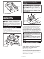
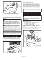
Securing the base
This tool should be bolted with two bolts to a level and
stable surface using the bolt holes provided in the tool's
base. This will help prevent tipping over and possible
personal injury.

5 ENGLISH
1
2
► 1. Bolt holes 2. Base
FUNCTIONAL
DESCRIPTION
WARNING: Always be sure that the tool is
switched off and the battery cartridge is removed
before adjusting or checking the functions on
the tool. Failure to switch off and remove the battery
cartridge may result in serious personal injury from
accidental start-up.
Unlocking/locking tool head
The tool head can be locked. Always lock the tool head
when not in use or carrying.
To unlock, depress the tool head slightly and push the
lock pin. To lock, return the lock pin while holding down
the tool head.
1
► 1. Lock pin
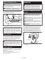
Installing or removing battery
cartridge
CAUTION: Always switch off the tool before
installing or removing of the battery cartridge.
CAUTION: Hold the tool and the battery car-
tridge rmly when installing or removing battery
cartridge. Failure to hold the tool and the battery
cartridge rmly may cause them to slip off your hands
and result in damage to the tool and battery cartridge
and a personal injury.
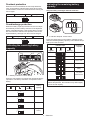
2
1
3
► 1. Red indicator 2. Button 3. Battery cartridge
To remove the battery cartridge, slide it from the tool
while sliding the button on the front of the cartridge.
To install the battery cartridge, align the tongue on the
battery cartridge with the groove in the housing and slip
it into place. Insert it all the way until it locks in place
with a little click. If you can see the red indicator on the
upper side of the button, it is not locked completely.
CAUTION: Always install the battery cartridge
fully until the red indicator cannot be seen. If not,
it may accidentally fall out of the tool, causing injury to
you or someone around you.
CAUTION: Do not install the battery cartridge
forcibly. If the cartridge does not slide in easily, it is
not being inserted correctly.
NOTE: The tool does not work with only one battery
cartridge.
Tool / battery protection system
The tool is equipped with a tool/battery protection sys-
tem. This system automatically cuts off power to the
motor to extend tool and battery life. The tool will auto-
matically stop during operation if the tool or battery is
placed under one of the following conditions.
Overload protection
When the tool is operated in a manner that causes it to
draw an abnormally high current, the tool automatically
stops. In this situation, turn the tool off and stop the
application that caused the tool to become overloaded.
Then turn the tool on to restart.

6 ENGLISH
Overheat protection
When the tool is overheated, the tool stops automati-
cally, and the battery indicator blink about 60 seconds.
In this situation, let the tool cool down before turning the
tool on again.
On Blinking
Overdischarge protection
When the battery capacity becomes low, the tool stops
automatically and the battery indicator of the depleted
battery cartridge will blink. If the product does not oper-
ate even when the switches are operated, remove the
depleted battery cartridge from the tool and charge it.
Blinking Off
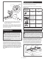
Indicating the remaining battery
capacity
1
1
2
► 1. Battery indicator 2. Check button
Press the check button to indicate the remaining battery
capacities. The battery indicators correspond to each
battery.
Battery indicator status Remaining
battery
capacity
On
Off
Blinking
50% to 100%
20% to 50%
0% to 20%
Charge the
battery
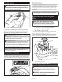
Indicating the remaining battery
capacity
Only for battery cartridges with the indicator
1
2
► 1. Indicator lamps 2. Check button
Press the check button on the battery cartridge to indi-
cate the remaining battery capacity. The indicator lamps
light up for a few seconds.
Indicator lamps Remaining
capacity
Lighted Off Blinking
75% to 100%
50% to 75%
25% to 50%
0% to 25%
Charge the
battery.
The battery
may have
malfunctioned.
NOTE: Depending on the conditions of use and the
ambient temperature, the indication may differ slightly
from the actual capacity.

7 ENGLISH
Switch action
WARNING: Before installing the battery car-
tridge into the tool, always check to see that the
switch trigger actuates properly and returns to
the "OFF" position when released.
1
2
► 1. Lock-off button 2. Switch trigger
To prevent the switch trigger from being accidentally
pulled, a lock-off button is provided. To start the tool,
press the lock-off button and pull the switch trigger.
Release the switch trigger to stop.
WARNING: NEVER defeat the lock-off button
by taping down or some other means. A switch with
a negated lock-off button may result in unintentional
operation and serious personal injury.
WARNING: NEVER use the tool if it runs when
you simply pull the switch trigger without press-
ing the lock-off button. A switch in need of repair
may result in unintentional operation and serious
personal injury. Return tool to a Makita service center
for proper repairs BEFORE further usage.
NOTICE: Do not pull the switch trigger hard
without pressing in the lock-off button. This can
cause switch breakage.
Load status indicator
The load status indicator shows the level of the load on
the motor during cutting operation. As the load on the
motor increases, the number of lighting lamp increases.
1
► 1. Load status indicator
Overload alert
If the motor is operated with excessive load, all lamps of
the load status indicator will blink. In this case, reduce
the load on the motor. If you continue to load the motor
while the load status indicator is blinking, the tool will
automatically stops in a few seconds due to overload
protection.
NOTE: If an excessive load is generated at once, the
tool automatically stops without blinking of the load
status indicator.
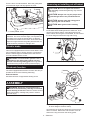
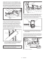
Interval between vise and guide
plate
CAUTION: After adjusting the interval
between the vise and the guide plate, make
sure that the guide plate is properly secured.
Insufcient xing may result in personal injury.
The following interval settings of the vise are available:
• 0 - 170 mm (0″- 6-11/16″) (original setting)
• 35 - 205 mm (1-3/8″- 8-1/16″)
• 70 - 240 mm (2-3/4″- 9-7/16″)
If your work requires different setting, proceed as fol-
lows to change the spacing or interval.
Loosen the screw on the guide plate. Move the guide
plate to the desired position then tighten the screw.
1
2
► 1. Screw 2. Guide plate
Cutting angle adjustment
CAUTION: After adjusting the angle of the
guide plate, make sure that the guide plate is
properly secured. Insufcient xing may result in
personal injury.
CAUTION: Do not operate the tool when
the material is not rmly secured with the vise
because of the cutting angle.

8 ENGLISH
Turn the lever counterclockwise. Move the guide plate
to the desired angle and fully tighten the lever.
1
2
► 1. Guide plate 2. Lever
NOTE: The scale on the guide plate is only a rough
indication. For more accurate angle, use a protractor
or triangle ruler. Keep the handle down so that the
cut-off wheel extends into the base. At the same time,
adjust the angle between the guide plate and the cut-
off wheel with a protractor or triangle ruler.
Electric brake
This tool is equipped with an electric wheel brake. If the
tool consistently fails to quickly stop the cut-off wheel
after the switch trigger is released, have the tool ser-
viced at a Makita service center.
CAUTION: The wheel brake system is not a
substitute for the safety guard. Never use tool
without a functioning safety guard. An unguarded
cut-off wheel may result in serious personal injury.
Electronic function
The tools equipped with electronic function are easy to
operate because of the following feature(s).
Soft start feature
Soft start because of suppressed starting shock.
ASSEMBLY
WARNING: Always be sure that the tool is
switched off and the battery cartridge is removed
before working on the tool. Failure to switch off and
remove the battery cartridge may result in serious
personal injury.
Removing or installing cut-off wheel
CAUTION: Be sure to tighten the toolless
clamp securely. Insufcient tightening may result in
severe injury.
CAUTION: Always use only the proper inner
and outer anges which are provided with the
tool.
CAUTION: Always lower the safety guard
after replacing the cut-off wheel.
CAUTION: Wear gloves when handling
wheels.
Raise the safety guard. Turn the toolless clamp coun-
terclockwise while holding down the shaft lock. Then
remove the toolless clamp, outer ange and cut-off
wheel. When removing the cut-off wheel, do not remove
the inner ange as well as the ring and O-ring.
1
2
► 1. Shaft lock 2. Toolless clamp
1
3
4
2
6
5
► 1. Inner ange 2. Ring 3. O-ring 4. Cut-off wheel
5. Outer ange 6. Toolless clamp
To install the cut-off wheel, follow the removal proce-
dures in reverse. Make sure to t the hole of cut-off
wheel to the ring and return the safety guard.

9 ENGLISH
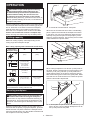
OPERATION
CAUTION: Proper handle pressure during
cutting and maximum cutting efciency can
be determined by the amount of sparks that is
produced while cutting. Do not force the cut
by applying excessive pressure on the handle.
Reduced cutting efciency, premature wheel wear, as
well as, possible damage to the tool, cut-off wheel or
workpiece may result.
Hold the handle rmly. Switch on the tool and wait until the
cut-off wheel attains full speed before lowering gently into
the cut. When the cut-off wheel contacts the workpiece,
gradually bear down on the handle to perform the cut.
When the cut is completed, switch off the tool and wait
until the cut-off wheel has come to a complete stop
before returning the handle to the fully elevated position.
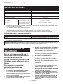
Cutting capacity
Maximum cutting capacity varies depending on the
cutting angle and workpiece shape.
Max. cutting capacity with a brand-new cut-off wheel
Cutting angle /
Workpiece shape
90° 45°
ø 127 mm
(ø 5″)
ø 127 mm
(ø 5″)
115 x 130 mm
(4-1/2″x 5-1/8″)
102 x 194 mm
(4″ x 7-5/8″)
70 x 233 mm
(2-3/4″ x 9-1/8″)
115 x 103 mm
(4-1/2″ x 4-1/16″)
119 x 119 mm
(4-11/16″ x
4-11/16″)
106 x 106 mm
(4-3/16″ x 4-3/16″)
137 x 137 mm
(5-3/8″ x 5-3/8″)
100 x 100 mm
(4″ x 4″)
NOTE: A workpiece thinner than 1.6 mm (1/16″) is
recommended for cutting with this tool.
Securing workpiece
CAUTION: Always place the thread holder on
the shaft threads when securing the workpiece.
Failure to do so may result in insufcient securing of
the workpiece. This could cause the workpiece to be
ejected or cause a dangerous breakage of the cut-off
wheel.
While the thread holder is lifted, the vise plate can be
moved in and out quickly. To grip a workpiece, push the
handle until the vise plate contacts the workpiece then
return the thread holder. Turn the handle clockwise until
the workpiece is securely retained.
1
2
3
► 1. Handle 2. Thread holder 3. Vise plate
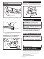
When the cut-off wheel has worn down considerably,
place a spacer block behind the workpiece as shown
in the gure. You can more efciently utilize the worn
wheel by using the mid point on the periphery of the
wheel to cut the workpiece. Use a sturdy and non-am-
mable material for a spacer block.
1
► 1. Spacer block
When cutting workpieces over 85 mm (3-3/8″) wide at
an angle, attach a straight piece of wood (spacer) over
190 mm (7-1/2″) long x 40 mm (1-9/16″) wide to the
guide plate as shown in the gure. Attach this spacer
with screws through the holes in the guide plate. Make
sure that the cut-off wheel does not contact the spacer
when the tool head is depressed.
1
2
3
4
► 1. Guide plate 2. Spacer block over 190 mm (7-1/2″)
long x 40 mm (1-9/16″) wide 3. Workpiece over 85
mm (3-3/8″) wide 4. Vise plate

10 ENGLISH
NOTICE: When using a spacer block, install the
guide plate to the position nearest to the neck of
the tool head.
When the cut-off wheel has worn down, raise the cutting
position by putting a spacer block which is slightly nar-
rower than the workpiece as shown in the gure. This
will help you to utilize the cut-off wheel economically.
1 2 3
4
► 1. Vise plate 2. Workpiece diameter 3. Guide plate
4. Spacer block width
Long workpieces must be supported by blocks on
either side so that it will be level with the base top. Use
non-ammable material for supporting blocks.
1
► 1. Supporting block
Carrying tool
Before carrying, remove the batteries and fold down the
tool head, and then lock it. Hold the handle when carrying.
MAINTENANCE
CAUTION:
Always be sure that the tool is
switched off and the battery cartridge is removed before
attempting to perform inspection or maintenance.
NOTICE: Never use gasoline, benzine, thinner,
alcohol or the like. Discoloration, deformation or
cracks may result.
To maintain product SAFETY and RELIABILITY,
repairs, any other maintenance or adjustment should
be performed by Makita Authorized or Factory Service
Centers, always using Makita replacement parts.
OPTIONAL ACCESSORIES
CAUTION:
These accessories or attachments
are recommended for use with your Makita tool spec-
ied in this manual. The use of any other accessories
or attachments might present a risk of injury to persons.
Only use accessory or attachment for its stated purpose.
If you need any assistance for more details regarding
these accessories, ask your local Makita Service Center.
• Abrasive cut-off wheels
• Makita genuine battery and charger
NOTE: Some items in the list may be included in the
tool package as standard accessories. They may
differ from country to country.
MAKITA LIMITED WARRANTY
Please refer to the annexed warranty sheet for the most
current warranty terms applicable to this product.If annexed
warranty sheet is not available, refer to the warranty details
set forth at below website for your respective country.
United States of America: www.makitatools.com
Canada: www.makita.ca
Other countries: www.makita.com

11 ESPAÑOL
ESPAÑOL (Instrucciones originales)
ESPECIFICACIONES
Modelo: XWL01
Diámetro del disco 355 mm (14″)
Diámetro del oricio 25,4 mm (1″)
Grosor máx. del disco 3 mm (1/8″)
Velocidad sin carga (RPM) 3 800 r/min
Tensión nominal 36 V c.c.
Dimensiones
(La x An x Al)
Con protección de seguridad
que no sea del tipo europeo
537 mm x 280 mm x 640 mm
(21-1/8″ x 11″ x 25-1/4″)
Peso neto Con protección de seguridad
que no sea del tipo europeo
15,6 - 16,3 kg (34,5 - 35,9 lbs)
• Debido a nuestro continuo programa de investigación y desarrollo, las especicaciones aquí incluidas están
sujetas a cambio sin previo aviso.
• Las especicaciones pueden variar de país a país.
• El peso puede variar en función de los accesorios, incluido el cartucho de batería. En la tabla se muestra la
combinación de peso más ligero y más pesado conforme al procedimiento 01/2014 de EPTA.
• La forma y el peso varían en función de las especicaciones las cuales son distintas en cada país.
Cartucho de batería y cargador aplicables
Cartucho de batería
BL1815N / BL1820B / BL1830 / BL1830B / BL1840B / BL1850B / BL1860B
Cargador DC18RC / DC18RD / DC18RE / DC18SD / DC18SE / DC18SF
• Algunos de los cartuchos de batería y cargadores enumerados arriba podrían no estar disponibles depen-
diendo de su área de residencia.
ADVERTENCIA: Use únicamente los cartuchos de batería y los cargadores indicados arriba. El uso de
cualquier otro cartucho de batería y cargador podría ocasionar una lesión y/o un incendio.
ADVERTENCIAS DE
SEGURIDAD
Por su propia seguridad lea el
manual de instrucciones antes
de usar la herramienta.
Utilice protección para los ojos.
Guárdelo como referencia en el
futuro.
Precauciones de seguridad
generales (para todas las
herramientas)
1. CONOZCA SU HERRAMIENTA ELÉCTRICA.
Lea el manual del usuario atentamente.
Conozca las aplicaciones y limitaciones de la
herramienta, así como los riesgos potenciales
especícos de la misma.
2. NO QUITE LOS PROTECTORES y manténgalos
en buen estado de funcionamiento.
3.
RETIRE LAS LLAVES DE AJUSTE Y DE APRIETE.
Adquiera el hábito de comprobar y ver que las
llaves de ajuste y de apriete hayan sido retiradas
de la herramienta antes de encenderla.
4. MANTENGA EL ÁREA DE TRABAJO LIMPIA.
Las áreas y bancos de trabajo desordenados
pueden ocasionar accidentes.
5. NO LAS UTILICE EN ENTORNOS
PELIGROSOS. No utilice las herramientas
eléctricas en lugares húmedos o mojados,
ni las exponga a la lluvia. Mantenga el área
de trabajo bien iluminada. No utilice la herra-
mienta en presencia de líquidos o gases
inamables.
6. MANTENGA ALEJADOS A LOS NIÑOS. Todos
los visitantes deberán ser mantenidos a una
distancia segura del área de trabajo.
7. MANTENGA EL TALLER A PRUEBA DE NIÑOS
con candados, interruptores maestros, o qui-
tando las llaves de encendido.
8. NO FUERCE LA HERRAMIENTA. Ésta hará el
trabajo mejor y de forma más segura a la velo-
cidad para la que fue diseñada.
9. UTILICE LA HERRAMIENTA APROPIADA. No
fuerce la herramienta ni los accesorios para
realizar un trabajo para el que no hayan sido
diseñados.

12 ESPAÑOL
10. USE UNA VESTIMENTA ADECUADA. No se
ponga ropa holgada, guantes, corbata, anillos,
pulseras, ni otro tipo de alhajas que puedan
engancharse en las piezas móviles. Se reco-
mienda utilizar calzado antiderrapante. Lleve
protección en el cabello para cubrirlo en caso
de tenerlo largo.
11. UTILICE SIEMPRE GAFAS DE SEGURIDAD.
Utilice también careta o máscara contra polvo
si la operación de corte es polvorienta. Los
anteojos de uso diario para la vista sólo tienen
lentes resistentes a impactos, NO son gafas de
seguridad.
12. SUJETE LA PIEZA DE TRABAJO. Utilice
pinzas o un tornillo de banco para sujetar la
pieza de trabajo cuando resulte práctico. Es
más seguro que utilizar la mano y además
dispondrá de ambas manos para manejar la
herramienta.
13. NO UTILICE LA HERRAMIENTA DONDE NO
ALCANCE. Mantenga los pies sobre suelo
rme y el equilibrio en todo momento.
14. DÉLE UN DEBIDO MANTENIMIENTO A LAS
HERRAMIENTAS. Mantenga las herramientas
aladas y limpias para un mejor desempeño y
mayor seguridad. Siga las instrucciones para
lubricar y cambiar los accesorios.
15. DESCONECTE LA BATERÍA DE LA
HERRAMIENTA antes de darle servicio y
cuando cambie accesorios tales como discos,
brocas, cuchillas y similares.
16. REDUZCA EL RIESGO DE ENCENDIDO
ACCIDENTAL. Asegúrese de que el interruptor
esté en la posición de apagado antes de inser-
tar la batería.
17. UTILICE LOS ACCESORIOS RECOMENDADOS.
Consulte el manual del usuario para ver los
accesorios recomendados. El uso de acceso-
rios no apropiados podría ocasionar riesgo de
lesiones personales.
18. NUNCA SE PARE ENCIMA DE LA
HERRAMIENTA. El volcar la herramienta o
tocar accidentalmente la herramienta de corte
podría ocasionar lesiones graves.
19. INSPECCIONE LAS PIEZAS DAÑADAS. Si un
protector u otra pieza están dañados, antes
de seguir utilizando la herramienta deberá
revisarlos cuidadosamente para cerciorarse
de que van a funcionar correctamente y rea-
lizar el trabajo para el que fueron diseñados
- verique la alineación de las piezas móviles,
la sujeción de las piezas móviles, que no
haya piezas rotas, el montaje y cualquier otra
condición que pueda afectar su operación.
Cualquier protector o pieza dañada deberá
repararse debidamente o reemplazarse.
20. DIRECCIÓN DE AVANCE. Avance la pieza de
trabajo hacia el disco o cuchilla solamente en
sentido contrario a la dirección de rotación de
los mismos.
21. NUNCA DEJE LA HERRAMIENTA
DESATENDIDA MIENTRAS ESTÉ EN MARCHA.
DESCONECTE LA ALIMENTACIÓN. No deje
la herramienta hasta que se haya detenido
completamente.
22. PIEZAS DE REPUESTO Cuando dé servicio
a la herramienta, utilice solamente piezas de
repuesto idénticas.
Uso y cuidado de la herramienta a batería
1. Asegúrese de que el interruptor esté en la
posición de apagado antes de insertar el cartu-
cho de batería. Insertar un cartucho de batería en
herramientas eléctricas con el interruptor encen-
dido puede ocasionar accidentes.
2. Recargue sólo con el cargador especicado
por el fabricante. Un cargador adecuado para
un tipo de cartucho de batería especíco puede
ocasionar riesgo de incendio al usarse con otro
cartucho de batería.
3. Use las herramientas eléctricas solo con sus
cartuchos de batería designados especíca-
mente para éstas. El uso de cualquier otro cartu-
cho de batería puede ocasionar riesgo de lesiones
e incendio.
4. Cuando no se esté usando el cartucho de
batería, manténgalo alejado de otros objetos
metálicos, como sujetapapeles (clips), mone-
das, llaves, clavos, tornillos u otros objetos
pequeños de metal que puedan crear una
conexión entre las terminales. Ocasionar un
cortocircuito en las terminales de la batería puede
provocar quemaduras o incendio.
5. En condiciones abusivas, podrá escapar
líquido de la batería; evite tocarlo. Si lo toca
accidentalmente, enjuague con agua. Si hay
contacto del líquido con los ojos, busque asis-
tencia médica. Puede que el líquido expulsado
de la batería cause irritación o quemaduras.
6. Desconecte el cartucho de batería de la herra-
mienta o coloque el interruptor en la posición
de bloqueo o de apagado antes de realizar
cualquier ajuste, cambiar accesorios o alma-
cenar la herramienta. Tales medidas de seguri-
dad preventivas reducirán el riesgo de poner en
marcha la herramienta de forma accidental.
7. El servicio de su herramienta eléctrica deberá
ser realizado por un técnico calicado usando
solamente piezas de repuesto idénticas. Esto
garantizará que se mantenga la seguridad de su
herramienta eléctrica.
8. No utilice una herramienta ni una batería que
estén dañadas o hayan sido modicadas. Las
baterías dañadas o modicadas podrían oca-
sionar una situación inesperada provocando un
incendio, explosión o riesgo de lesiones.
9. No exponga la herramienta ni la batería al
fuego ni a una temperatura excesiva. La expo-
sición al fuego o a una temperatura superior a los
130 °C podría causar una explosión.
10. Siga todas las instrucciones para la carga y
evite cargar la herramienta o la batería fuera
del rango de temperatura especicado en
las instrucciones. Una carga inadecuada o a
una temperatura fuera del rango especicado
podría dañar la batería e incrementar el riesgo de
incendio.

13 ESPAÑOL
Normas especícas de seguridad
NO deje que la comodidad o familiaridad con el
producto (a base de utilizarlo repetidamente) sus-
tituya la estricta observancia de las normas de
seguridad para la tronzadora de metal. El no utilizar
esta herramienta de forma segura o correcta podría
ocasionarle lesiones personales graves.
1. Use protección para los oídos durante los
períodos de operación prolongados.
2. Utilice sólo discos cuya velocidad de opera-
ción máxima sea al menos tan alta como la
velocidad sin carga de la herramienta (r/min ó
RPM) marcada en la placa de características
de la herramienta. Utilice sólo discos de corte
reforzados con bra de vidrio.
3. Revise cuidadosamente el disco de corte para
ver que no tenga grietas o daños antes de la
operación. Reemplace de inmediato el disco
en caso de presentar grietas o daños. Haga
funcionar la herramienta (con protector) sin
carga alrededor de un minuto, sosteniendo la
herramienta lejos de las demás personas. Si el
disco presenta fallas, es posible que se separe
durante esta prueba.
4. Asegure el disco de corte cuidadosamente.
5. Utilice solamente las bridas especicadas
para esta herramienta.
6. Tenga cuidado de no dañar el eje, las bridas
(especialmente la supercie de instalación)
o el perno. Si estas piezas se dañan el disco
podría romperse.
7. No opere la herramienta sin los protectores
puestos. Verique que el protector de el disco
cierre correctamente antes de cada uso. No
opere la herramienta si el protector el disco
no se mueve libremente o no cierra de manera
instantánea. Nunca je o sujete el protector de
el disco en la posición abierta.
8. Sostenga rmemente el mango.
9. Mantenga las manos alejadas de las piezas
giratorias.
10. Asegúrese de que el disco de corte no esté
haciendo contacto con la pieza de trabajo
antes de activar el interruptor.
11. Antes de utilizar la herramienta en una pieza
de trabajo denitiva, déjela funcionar durante
un rato. Observe si hay vibración o bamboleo
que pueda indicar una instalación incorrecta o
un disco mal equilibrada.
12. Tenga cuidado con las chispas que se des-
prenden durante la operación. Éstas pueden
ocasionar lesiones o prender fuego a los mate-
riales combustibles.
13. Elimine del área de trabajo el material o resi-
duos que podrían encenderse a causa de las
chispas. Asegúrese de que no haya nadie en el
área donde se desprendan las chispas. Tenga
cerca un extintor de incendios cargado y en
buenas condiciones.
14. Solo utilice el borde cortante del disco de
corte. Nunca utilice la supercie lateral.
15. No intente mantener el gatillo en la posición de
ENCENDIDO.
16. Si el disco de corte se detiene durante la ope-
ración, o si hace un ruido extraño o comienza
a vibrar, apague la herramienta de inmediato.
17. Apague la herramienta y espere a que el disco
de corte se detenga antes de mover la pieza de
trabajo o cambiar los ajustes.
18. No toque la pieza de trabajo inmediatamente
después de la operación, ya que podría estar
extremadamente caliente y provocarle quema-
duras en la piel.
19. Almacene los discos sólo en un lugar seco.
20. Antes de cada uso, observe si hay temblor o
vibración excesiva que pudiera ser causada
por una instalación incorrecta o un disco mal
equilibrado.
GUARDE ESTAS
INSTRUCCIONES.
ADVERTENCIA: EL USO INCORRECTO o el
no seguir las normas de seguridad indicadas en
este manual de instrucciones puede ocasionar
lesiones personales graves.
ADVERTENCIA: Este aparato no se destina
para utilizarse por personas (incluyendo niños)
cuyas capacidades físicas, sensoriales o menta-
les sean diferentes o estén reducidas o carezcan
de experiencia o de conocimiento, a menos
que dichas personas reciban una supervisión o
capacitación para el funcionamiento del aparato
por una persona responsable de su seguridad.
Los niños deben supervisarse para asegurar que
ellos no empleen los aparatos como juguete. Si
el cordón de alimentación es dañado, éste debe
sustituirse por el fabricante, por su agente de
servicio autorizado o por personal calicado con
el n de evitar un peligro.
Símbolos
A continuación se muestran los símbolos utilizados
para la herramienta.
volts o voltios
corriente directa o continua
velocidad sin carga
revoluciones o alternaciones por minuto,
frecuencia de rotación
Instrucciones importantes de
seguridad para el cartucho de
batería
1. Antes de utilizar el cartucho de batería, lea
todas las instrucciones e indicaciones de
precaución en el (1) el cargador de batería, (2)
la batería, y (3) el producto con el que se utiliza
la batería.
2. No desarme el cartucho de batería.

14 ESPAÑOL
3. Si el tiempo de operación se ha acortado en
exceso, deje de operar de inmediato. Podría
correrse el riesgo de sobrecalentamiento,
posibles quemaduras e incluso explosión.
4. En caso de que ingresen electrolitos en sus
ojos, enjuáguelos bien con agua limpia y con-
sulte de inmediato a un médico. Esto podría
ocasionar pérdida de visión.
5. Evite cortocircuitar el cartucho de batería:
(1) No toque las terminales con ningún mate-
rial conductor.
(2) Evite guardar el cartucho de batería en un
cajón junto con otros objetos metálicos,
tales como clavos, monedas, etc.
(3) No exponga el cartucho de batería al
agua o la lluvia.
Un cortocircuito en la batería puede causar
un ujo grande de corriente, sobrecalenta-
miento, posibles quemaduras e incluso una
descompostura.
6. No guarde la herramienta ni el cartucho de
batería en lugares donde la temperatura pueda
alcanzar o exceder los 50°C (122°F).
7. Nunca incinere el cartucho de batería incluso
en el caso de que esté dañado seriamente o
ya no sirva en absoluto. El cartucho de batería
puede explotar si se tira al fuego.
8. Tenga cuidado de no dejar caer ni golpear la
batería.
9. No use una batería dañada.
10. Las baterías de ión de litio están sujetas a los
requisitos reglamentarios en materia de bie-
nes peligrosos.
Para el trasporte comercial, por ej., mediante
terceros o agentes de transporte, se deben tomar
en cuenta los requisitos especiales relativos al
empaque y el etiquetado.
Para efectuar los preparativos del artículo que se
va a enviar, se requiere consultar a un experto
en materiales peligrosos. Si es posible, consulte
además otras regulaciones nacionales más deta-
lladas.
Pegue o cubra con cinta adhesiva los contactos
abiertos y empaque la batería de manera que ésta
no pueda moverse dentro del paquete.
11. Siga las regulaciones locales relacionadas al
desecho de las baterías.
12. Utilice las baterías únicamente con los pro-
ductos especicados por Makita. Instalar las
baterías en productos que no cumplan con los
requisitos podría ocasionar un incendio, un calen-
tamiento excesivo, una explosión o una fuga de
electrolito.
GUARDE ESTAS
INSTRUCCIONES.
PRECAUCIÓN: Utilice únicamente baterías
originales de Makita. El uso de baterías no origina-
les de Makita, o de baterías alteradas, puede ocasio-
nar que las baterías exploten causando un incendio,
lesiones personales y daños. Asimismo, esto inva-
lidará la garantía de Makita para la herramienta y el
cargador Makita.
Consejos para alargar al máximo
la vida útil de la batería
1. Cargue el cartucho de batería antes de que
se descargue completamente. Pare siem-
pre la operación y cargue el cartucho de
batería cuando note menos potencia en la
herramienta.
2. No cargue nunca un cartucho de batería que
esté completamente cargado. La sobrecarga
acortará la vida de servicio de la batería.
3. Cargue el cartucho de batería a una tempera-
tura ambiente de 10 °C - 40 °C (50 °F - 104 °F).
Si un cartucho de batería está caliente, déjelo
enfriar antes de cargarlo.
4. Cargue el cartucho de batería si no va a utili-
zarlo durante un período prolongado (más de
seis meses).
INSTALACIÓN
ADVERTENCIA: Esta herramienta produce
chispas al cortar una pieza de trabajo. No instale
esta herramienta en un lugar donde las chispas
que se desprenden de ella podrían prender fuego
a los materiales inamables y/o explosivos.
Asimismo, asegúrese de que no haya este tipo
de materiales cerca de la herramienta antes de
empezar la operación.
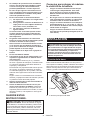
Fijación de la base
Esta herramienta debe atornillarse con dos pernos a
una supercie nivelada y estable, utilizando los oricios
para pernos que se encuentran en la base de la herra-
mienta. Esto ayudará a evitar que la herramienta se
vuelque y pueda ocasionar lesiones personales.
1
2
► 1. Oricios para pernos 2. Base

15 ESPAÑOL
DESCRIPCIÓN DEL
FUNCIONAMIENTO
ADVERTENCIA: Asegúrese siempre de que
la herramienta esté apagada y el cartucho de
batería haya sido extraído antes de realizar cual-
quier ajuste o revisión del funcionamiento de la
herramienta. El no apagar y extraer el cartucho de
batería puede provocar lesiones personales graves a
causa de un encendido accidental.
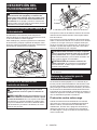
Desbloqueo/bloqueo del cabezal de
la herramienta
El cabezal de la herramienta puede bloquearse.
Siempre bloquee el cabezal de la herramienta cuando
no la esté usando o la esté cargando.
Para desbloquear, presione ligeramente el cabezal de
la herramienta y empuje el pasador de bloqueo. Para
bloquear, regrese el pasador de bloqueo manteniendo
presionado el cabezal de la herramienta.
1
► 1. Pasador de bloqueo
Instalación o extracción del
cartucho de batería
PRECAUCIÓN: Apague siempre la herra-
mienta antes de colocar o quitar el cartucho de
batería.
PRECAUCIÓN: Sujete la herramienta y el car-
tucho de la batería con rmeza al colocar o quitar
el cartucho de batería. Si no se sujeta con rmeza la
herramienta y el cartucho de batería, puede ocasio-
nar que se resbalen de sus manos causando daños
a la herramienta y al cartucho de batería, así como
lesiones a la persona.
2
1
3
► 1. Indicador rojo 2. Botón 3. Cartucho de batería
Para quitar el cartucho de batería, deslícelo de la herra-
mienta mientras desliza el botón sobre la parte delan-
tera del cartucho.
Para colocar el cartucho de batería, alinee la lengüeta
sobre el cartucho de batería con la ranura en la carcasa
y deslice en su lugar. Inserte por completo hasta que
se je en su lugar con un pequeño clic. Si puede ver el
indicador rojo del lado superior del botón, esto indica
que no ha quedado jo por completo.
PRECAUCIÓN:
Introduzca siempre completa-
mente el cartucho de batería hasta que el indicador
rojo no pueda verse. Si no, podría accidentalmente
salirse de la herramienta y caer al suelo causando una
lesión a usted o alguien a su alrededor.
PRECAUCIÓN: No instale el cartucho de
batería a la fuerza. Si el cartucho no se desliza al
interior fácilmente, se debe a que no está siendo
insertado correctamente.
NOTA: La herramienta no funciona sólo con un cartu-
cho de batería.
Sistema de protección para la
herramienta/batería
La herramienta está equipada con un sistema de pro-
tección para la herramienta/batería. Este sistema corta
en forma automática el suministro de energía al motor
para prolongar la vida útil de la herramienta y la batería.
La herramienta se detendrá automáticamente durante
la operación si la herramienta o la batería se someten a
una de las siguientes condiciones. En algunas condicio-
nes, los indicadores pueden encenderse.
Protección contra sobrecarga
Cuando la herramienta sea utilizada de una manera
que cause que consuma una cantidad anormalmente
alta de corriente, la herramienta se detendrá auto-
máticamente. En este caso, apague la herramienta y
detenga la aplicación que causó que la herramienta
se sobrecargara. Luego encienda la herramienta para
volver a arrancarla.

16 ESPAÑOL
Protección contra sobrecalentamiento
Cuando la herramienta se sobrecaliente, ésta se detendrá
automáticamente y el indicador de batería parpadeará
alrededor de 60 segundos. En este caso, permita que la
herramienta se enfríe antes de volver a encenderla.
Encendido Parpadeando
Protección contra sobredescarga
Cuando la capacidad de la batería sea baja, la herra-
mienta se detendrá automáticamente y el indicador de
cartucho de batería agotado comenzará a parpadear. Si
el producto no funciona incluso cuando los interruptores
están siendo operados, retire el cartucho de batería
agotado de la herramienta y cárguelo.
Parpadeando Apagada
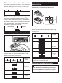
Indicación de capacidad restante de la batería
1
1
2
► 1. Indicador de batería 2. Botón de vericación
Oprima el botón de vericación para indicar las capa-
cidades restantes de la batería. Los indicadores de
batería corresponden a cada batería.
Estado del indicador de batería Capacidad
restante de la
batería
Encendido
Apagado
Parpadeando
50% a 100%
20% a 50%
0% a 20%
Cargar la
batería
Indicación de la capacidad restante
de la batería
Únicamente para cartuchos de batería con el
indicador
1
2
► 1. Luces indicadoras 2. Botón de vericación
Oprima el botón de vericación en el cartucho de la
batería para que indique la capacidad restante de la
batería. Las luces indicadoras se iluminarán por algu-
nos segundos.
Luces indicadoras Capacidad
restante
Iluminadas Apagadas Parpadeando
75% a 100%
50% a 75%
25% a 50%
0% a 25%
Cargar la
batería.
La batería
pudo haber
funcionado
mal.
NOTA: Dependiendo de las condiciones de uso y
la temperatura ambiente, la indicación podrá diferir
ligeramente de la capacidad real.
Accionamiento del interruptor
ADVERTENCIA: Antes de insertar el car-
tucho de batería en la herramienta, compruebe
siempre y cerciórese de que el gatillo interruptor
se acciona debidamente y que vuelve a la posi-
ción “OFF” (apagado) cuando lo suelta.

17 ESPAÑOL
1
2
► 1. Botón de desbloqueo 2. Gatillo interruptor
El botón de desbloqueo es suministrado para evitar
jalar accidentalmente el gatillo interruptor. Para encen-
der la herramienta, presione el botón de desbloqueo y
jale el gatillo interruptor. Para detenerla, suelte el gatillo
interruptor.
ADVERTENCIA: NUNCA inhabilite el botón
de desbloqueo manteniéndolo presionado con
cinta adhesiva o mediante otro método. El uso
de un interruptor con un botón de desbloqueo inha-
bilitado puede ocasionar una operación accidental y
lesiones personales graves.
ADVERTENCIA: NUNCA use la herramienta
si se activa simplemente al jalar el gatillo inte-
rruptor sin que haya presionado el botón de
desbloqueo. El uso de un interruptor que requiere
reparación puede ocasionar una operación accidental
y lesiones personales graves. Lleve la herramienta
a un centro de servicio Makita para las reparaciones
apropiadas ANTES de continuar su uso.
AVISO: No jale fuertemente el gatillo interruptor
sin presionar el botón de desbloqueo. Esto podría
dañar el interruptor.
Indicador de estado de carga
El indicador de estado de carga muestra el nivel de
la carga en el motor durante la operación de corte. A
medida que aumenta la carga en el motor, más luces
indicadoras se encienden.
1
► 1. Indicador de estado de carga
Alerta de sobrecarga
Si el motor es operado con una carga excesiva, todas
las luces del indicador de estado de carga parpadea-
rán. En este caso, reduzca la carga en el motor. Si
continúa cargando el motor mientras el indicador de
estado de carga está parpadeando, la herramienta se
detendrá automáticamente en pocos segundos debido
a la protección contra sobrecarga.
NOTA: Si se genera una carga excesiva de golpe, la
herramienta se detendrá automáticamente sin que el
indicador de estado de carga haya parpadeado.
Intervalo entre el tornillo de banco y
la placa guía
PRECAUCIÓN: Después de ajustar el inter-
valo entre el tornillo de banco y la placa guía,
asegúrese de que la placa guía esté bien asegu-
rada. Una jación incorrecta podría ocasionar lesio-
nes personales.
Se pueden realizar los siguientes ajustes de intervalos
para el tornillo de banco:
• 0 - 170 mm (0″- 6-11/16″) (ajuste original)
• 35 - 205 mm (1-3/8″- 8-1/16″)
• 70 - 240 mm (2-3/4″- 9-7/16″)
Si su trabajo requiere un ajuste distinto, haga lo que
se indica a continuación para cambiar el espacio o
intervalo.
Aoje el tornillo en la placa guía. Desplace la placa guía
a la posición deseada y luego apriete el tornillo.
1
2
► 1. Tornillo 2. Placa guía

18 ESPAÑOL
Ajuste del ángulo de corte
PRECAUCIÓN: Después de ajustar el ángulo
de la placa guía, asegúrese de que la placa guía
esté bien asegurada. Una jación incorrecta podría
ocasionar lesiones personales.
PRECAUCIÓN: No opere la herramienta
cuando el material no esté rmemente asegurado
con el tornillo de banco debido al ángulo de corte.
Gire la palanca en sentido inverso al de las manecillas
del reloj. Desplace la placa guía al ángulo deseado y
apriete completamente la palanca.
1
2
► 1. Placa guía 2. Palanca
NOTA: La escala en la placa guía es solamente un
indicador aproximado. Para un ángulo más preciso,
use un transportador o una escuadra. Mantenga el
mango hacia abajo de tal forma que la rueda corta-
dora se extienda dentro de la base. Al mismo tiempo,
ajuste el ángulo entre la placa guía y el disco de corte
con un transportador o una escuadra.
Freno eléctrico
La herramienta está equipada con un freno eléctrico
para el disco. Si con frecuencia la herramienta no logra
detener rápidamente el disco de corte tras soltar el
gatillo interruptor, lleve la herramienta a un centro de
servicio Makita para que le den servicio.
PRECAUCIÓN: El sistema de frenado del
disco no es un sustituto de la protección de segu-
ridad. Nunca use la herramienta si la protección
de seguridad no funciona. El uso de un disco de
corte sin protección podría ocasionar lesiones perso-
nales graves.
Función eléctrica
Las herramientas equipadas con funciones electrónicas
son fáciles de operar gracias a la(s) característica(s) a
continuación.
Función de arranque suave
Permite el arranque suave gracias a que reduce el
impacto de encendido.
MONTAJE
ADVERTENCIA: Asegúrese siempre de que
la herramienta esté apagada y el cartucho de
batería extraído antes de realizar algún trabajo
con la herramienta. No seguir esta indicación de
retirar el cartucho de la batería de la herramienta
puede que resulte en graves lesiones personales.
Extracción o instalación del disco
de corte
PRECAUCIÓN: Asegúrese de apretar bien
la abrazadera que no requiere herramienta. El
no apretar lo suciente podría ocasionar lesiones
graves.
PRECAUCIÓN: Siempre utilice únicamente la
brida interior y exterior apropiadas que se sumi-
nistran con la herramienta.
PRECAUCIÓN: Siempre baje la protección
de seguridad después de reemplazar el disco de
corte.
PRECAUCIÓN: Use guantes cuando mani-
pule los discos.
Levante la protección de seguridad. Gire la abrazadera
que no requiere herramienta en sentido inverso al de
las manecillas del reloj manteniendo presionado el
bloqueo del eje. Luego retire la abrazadera que no
requiere herramienta, la brida exterior y la rueda cor-
tadora. Cuando extraiga el disco de corte, no retire la
brida interior ni tampoco el anillo y el anillo en O.
1
2
► 1. Bloqueo del eje 2. Abrazadera que no requiere
herramienta

19 ESPAÑOL
1
3
4
2
6
5
► 1. Brida interior 2. Anillo 3. Anillo en O 4. Disco
de corte 5. Brida exterior 6. Abrazadera que no
requiere herramienta
Para instalar la rueda cortadora, siga el procedimiento
de extracción en orden inverso. Asegúrese que el ori-
cio del disco de corte encaje en el anillo y regrese la
protección de seguridad.
OPERACIÓN
PRECAUCIÓN: La presión adecuada sobre
el mango durante el corte y la máxima ecacia
del corte se pueden determinar por la cantidad
de chispas al realizar el corte. No fuerce el corte
aplicando una presión excesiva sobre el mango.
Si lo hace, podría disminuir la ecacia del corte y
provocar el desgaste prematuro del disco, así como
posibles daños a la herramienta, a la rueda cortadora
o a la pieza de trabajo.
Sostenga el mango con rmeza. Encienda la herra-
mienta y espere a que el disco de corte alcance la
velocidad máxima antes de bajarlo suavemente para
introducirlo en el corte. Cuando el disco de corte haga
contacto con la pieza de trabajo, haga presión gradual-
mente sobre el mango para realizar el corte. Una vez
que haya completado el corte, apague la herramienta y
espere hasta que el disco de corte se haya detenido
por completo antes de volver a subir totalmente el
mango.
Capacidad de corte
La capacidad máxima de corte varía según el ángulo de
corte y la forma de la pieza de trabajo.
Capacidad máx. de corte con una un disco comple-
tamente nuevo
Ángulo de corte /
Forma de la pieza
de trabajo
90° 45°
ø127 mm
(ø5″)
ø127 mm
(ø5″)
115 x 130 mm
(4-1/2″x 5-1/8″)
102 x 194 mm
(4″ x 7-5/8″)
70 x 233 mm
(2-3/4″ x 9-1/8″)
115 x 103 mm
(4-1/2″ x 4-1/16″)
119 x 119 mm
(4-11/16″ x
4-11/16″)
106 x 106 mm
(4-3/16″ x 4-3/16″)
137 x 137 mm
(5-3/8″ x 5-3/8″)
100 x 100 mm
(4″ x 4″)
NOTA:
Para cortar con esta herramienta, se recomienda usar
una pieza de trabajo con un espesor inferior a 1,6 mm (1/16″).
Aseguramiento de la pieza de trabajo
PRECAUCIÓN:
Al asegurar la pieza de trabajo,
siempre coloque el sujetador de roscas en las roscas
del eje. El no hacerlo podría dar como resultado que la
pieza de trabajo no quedara bien asegurada. Esto podría
ocasionar que la pieza de trabajo saliera despedida o
que el disco de corte se rompiera de manera peligrosa.
Mientras se levanta el sujetador de roscas, la placa del torni-
llo de banco puede desplazarse hacia adentro y hacia afuera
rápidamente. Para sujetar una pieza de trabajo, empuje el
mango hasta que la placa del tornillo de banco haga contacto
con la pieza de trabajo y luego regrese el sujetador de ros-
cas. Gire el mango en el sentido de las manecillas del reloj
hasta que la pieza de trabajo quede sujetada con rmeza.
1
2
3
►
1. Mango 2. Sujetador de roscas 3. Placa del tornillo de banco

20 ESPAÑOL
Cuando el disco de corte se haya desgastado consi-
derablemente, coloque un bloque espaciador detrás
de la pieza de trabajo tal como se muestra en la gura.
Puede aprovechar el disco desgastada en forma más
ecaz utilizando el punto medio de la periferia de el
disco para cortar la pieza de trabajo. Utilice un material
resistente y no inamable para el bloque espaciador.
1
► 1. Bloque espaciador
Cuando corte piezas de trabajo de más de 85 mm
(3-3/8″) de ancho en un ángulo, coloque en la placa
guía una pieza de madera recta (espaciador) de más
de 190 mm (7-1/2″) de largo x 40 mm (1-9/16″) de
ancho, tal como se muestra en la gura. Fije este
espaciador insertando tornillos en los oricios de la
placa guía. Asegúrese de que el disco de corte no esté
haciendo contacto con el espaciador cuando el cabezal
de la herramienta sea presionado.
1
2
3
4
► 1. Placa guía 2. Bloque espaciador de más de 190
mm (7-1/2″) de largo x 40 mm (1-9/16″) de ancho
3. Pieza de trabajo de más de 85 mm (3-3/8″) de
ancho 4. Placa del tornillo de banco
AVISO: Cuando use un bloque espaciador, ins-
tale la placa guía en la posición más cercana al
cuello del cabezal de la herramienta.
Cuando el disco de corte se haya desgastado, aumente
la posición de corte colocando un bloque espaciador
que sea ligeramente más angosto que la pieza de tra-
bajo, tal como se muestra en la gura. Esto le ayudará
a utilizar el disco de corte de manera eciente.
1 2 3
4
► 1. Placa del tornillo de banco 2. Diámetro de la
pieza de trabajo 3. Placa guía 4. Anchura del blo-
que espaciador
Las piezas de trabajo largas deben estar sujetadas por
bloques a ambos lados de forma que queden nivelados
con la parte superior de la base. Utilice un material no
inamable para los bloques de sujeción.
1
► 1. Bloque de sujeción

21 ESPAÑOL
Transporte de la herramienta
Antes de transportar la herramienta, retire las bate-
rías, doble hacia abajo el cabezal de la herramienta y
luego bloquéelo. Sostenga el mango al transportar la
herramienta.
MANTENIMIENTO
PRECAUCIÓN: Asegúrese siempre de que la
herramienta esté apagada y el cartucho de batería
extraído antes de intentar realizar una inspección
o mantenimiento.
AVISO: Nunca use gasolina, bencina, diluyente
(tíner), alcohol o sustancias similares. Puede que
esto ocasione grietas o descoloramiento.
Para mantener la SEGURIDAD y FIABILIDAD del pro-
ducto, las reparaciones, y cualquier otra tarea de man-
tenimiento o ajuste deberán ser realizadas en centros
de servicio autorizados o de fábrica Makita, empleando
siempre repuestos Makita.
ACCESORIOS
OPCIONALES
PRECAUCIÓN: Estos accesorios o aditamen-
tos están recomendados para utilizarse con su
herramienta Makita especicada en este manual.
El empleo de cualquier otro accesorio o aditamento
puede conllevar el riesgo de lesiones personales.
Utilice los accesorios o aditamentos solamente para
su n establecido.
Si necesita cualquier ayuda para más detalles en
relación con estos accesorios, pregunte a su centro de
servicio local Makita.
• Discos de corte abrasivos
• Batería y cargador originales de Makita
NOTA: Algunos de los artículos en la lista pueden
incluirse en el paquete de la herramienta como acce-
sorios estándar. Éstos pueden variar de país a país.
GARANTÍA LIMITADA DE MAKITA
Ésta Garantía no aplica para México
Consulte la hoja de la garantía anexa para ver los
términos más vigentes de la garantía aplicable a este
producto. En caso de no disponer de esta hoja de
garantía anexa, consulte los detalles sobre la garantía
descritos en el sitio web de su país respectivo indicado
a continuación.
Estados Unidos de América: www.makitatools.com
Canadá: www.makita.ca
Otros países: www.makita.com

22

23

Some dust created by power sanding, sawing, grinding, drilling, and other
construction activities contains chemicals known to the State of California
to cause cancer, birth defects or other reproductive harm. Some examples
of these chemicals are:
• lead from lead-based paints,
• crystalline silica from bricks and cement and other masonry products, and
• arsenic and chromium from chemically-treated lumber.
Your risk from these exposures varies, depending on how often you do this
type of work. To reduce your exposure to these chemicals: work in a well
ventilated area, and work with approved safety equipment, such as those
dust masks that are specially designed to filter out microscopic particles.
WARNING
< USA only >
ADVERTENCIA
Algunos polvos creados por el lijado, aserrado, esmerilado, taladrado y
otras actividades de la construcción contienen sustancias químicas
reconocidas por el Estado de California como causantes de cáncer, defectos
de nacimiento y otros peligros de reproducción. Algunos ejemplos de estos
productos químicos son:
• plomo de pinturas a base de plomo,
• sílice cristalino de ladrillos y cemento y otros productos de albañilería, y
• arsénico y cromo de maderas tratadas químicamente.
El riesgo al que se expone varía, dependiendo de la frecuencia con la que
realice este tipo de trabajo. Para reducir la exposición a estos productos
químicos: trabaje en un área bien ventilada y póngase el equipo de seguridad
indicado, tal como las máscaras contra polvo que están especialmente
diseñadas para filtrar partículas microscópicas.
< Sólo en los Estados Unidos >
Makita Corporation
3-11-8, Sumiyoshi-cho,
Anjo, Aichi 446-8502 Japan
www.makita.com
885648A944
XWL01-1
EN, ESMX
20180529
-
 1
1
-
 2
2
-
 3
3
-
 4
4
-
 5
5
-
 6
6
-
 7
7
-
 8
8
-
 9
9
-
 10
10
-
 11
11
-
 12
12
-
 13
13
-
 14
14
-
 15
15
-
 16
16
-
 17
17
-
 18
18
-
 19
19
-
 20
20
-
 21
21
-
 22
22
-
 23
23
-
 24
24


Makita XWL01PT Manual de usuario
- Categoría
- Herramientas eléctricas
- Tipo
- Manual de usuario
- Este manual también es adecuado para
en otros idiomas
- English: Makita XWL01PT User manual
Artículos relacionados
-
Makita LW1400X2 Manual de usuario
-
Makita XSR01Z-XAG12Z1 Manual de usuario
-
-
-
Makita XT331PTX Manual de usuario
-
-
-
-
-