Halsey Taylor HTHB-HVRGRN8BL-WF Guía de instalación
- Categoría
- Artículos sanitarios
- Tipo
- Guía de instalación
El Halsey Taylor HTHB-HVRGRN8BL-WF es un enfriador de agua y estación de llenado de botellas con una variedad de características para mantenerte hidratado y refrescado. El sistema de filtración de tres etapas elimina los contaminantes, mientras que el compresor de alta eficiencia mantiene el agua fría y refrescante. El diseño resistente al vandalismo lo hace ideal para áreas públicas, y el llenador de botellas incorporado permite un llenado rápido y fácil.
El Halsey Taylor HTHB-HVRGRN8BL-WF es un enfriador de agua y estación de llenado de botellas con una variedad de características para mantenerte hidratado y refrescado. El sistema de filtración de tres etapas elimina los contaminantes, mientras que el compresor de alta eficiencia mantiene el agua fría y refrescante. El diseño resistente al vandalismo lo hace ideal para áreas públicas, y el llenador de botellas incorporado permite un llenado rápido y fácil.


Transcripción de documentos
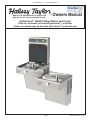
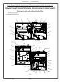
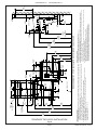
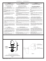
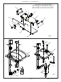
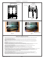
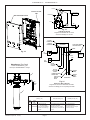
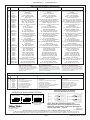
HVRGRN8BLWS*1C HVRGRN8BLWSNF*1C MANUAL DEL PROPIETARIO HALSEY TAYLOR MANUEL DE L'UTILISATION HALSEY TAYLOR Owners Manual Hydroboost® Bottle Filling Station and Cooler Estación de llenado de botella Hydroboost® y enfriador Station de remplissage de bouteille Hydroboost® et refroidisseur Page 1 1000001740 (Rev. N - 01/19) HVRGRN8BLWS*1C HVRGRN8BLWSNF*1C Note: Danger! Electric shock hazard. Disconnect power before servicing unit. Nota: peligro! Peligro de descarga eléctrica. Desconecte antes de reparar la unidad. Remarque : Danger ! Risque d'électrocution. Débrancher avant de réparer l'appareil. Pictured is unit only without bottle filler. Uses HFC-134A refrigerant Usa refrigerante HFC-134A Utilise du fluide frigorigéne HFC-134A 3 24 7 15 5 3 18 16 21 19 19 16 8 25 See Fig. 5 4B 36 36 35 19 12 4A See Fig. 3 36 28 19 7 30 34 21 19 33 31 11 14 29 23 32 13 Fig. 1 1000001740 (Rev. N - 01/19) Page 2 6 33 22 Page 3 STANDARD TWO-LEVEL INSTALLATION Fig. 2 20 3/8" 518mm 7 1/4" 185mm E 2 9/16" 65mm F 1 3/8" 6 1/2" 165mm 35mm 5/16" (8mm) DIA. (10 HOLES) 5 3/4" 146mm 15" 381mm 5" 127mm 4 9/16" 116mm 7" 178mm 7" 178mm 10" 254mm 2 7/16" 63mm 11/16" 18mm B 6 1/4" 159mm CL 3 1/2" 89mm 4 1/2" 114mm 1 3/8" 1 3/8" 35mm 35mm 5 3/4" 146mm 5 3/4" 146mm 18 1/16" 459mm E 25 1/8" 638mm 20 1/8" 511mm 18 3/4" 476mm F A D 13 7/8" 352mm 5 3/4" 146mm 27" 686mm ADA REQURIEMENTS* 31 15/16" 811mm RIM HEIGHT 33" 838mm ORIFICE HEIGHT 39 7/16" 1002mm ORIFICE HEIGHT 2 5/8" 67mm C 12 5/16" 313mm 4 1/8" 105mm 8" 203mm HANGER BRACKET 18 5/8" 472mm 3 9/16" 90mm 6 3/4" 172mm 18 7/8" 479mm LEGEND/LEYENDA/LÉGENDE D = ELECTRICAL SUPPLY (3) WIRE RECESSED BOX DUPLEX OUTLET** SUMINISTRO ELÉCTRICO (3) CAJA ENCHUFE DE ALAMBRE SALIDA DÚPLEX ALIMENTATION ÉLECTRIQUE (3) BOÎTIER ENCASTRÉ E = INSURE PROPER VENTILATION BY MAINTAINING 6” (152 mm) (MIN.) CLEARANCE FROM CABINET LOUVERS TO WALL. ASEGURE UNA VENTILACIÓN ADECUADA MANTENIENDO UN ESPACIO E 6” (152 mm) (MÍN.) DE HOLGURA ENTRE LA REJILLA DE VENTILACIÓN DEL MUEBLE Y LA PARED. ASSUREZ-VOUS UNE BONNE VENTILATION EN GARDANT 6” (152 mm) (MIN.) ENTRE LES ÉVENTS DE L’ENCEINTE ET LE MUR. F = 7/16 BOLT HOLES FOR FASTENING UNIT TO WALL AGUJEROS DE LAS TUERCAS DE 7/16 PARA SUJETAR LA UNIDAD A LA PARED TROUS D’ÉCROUS 7/16 POUR FIXER L’APPAREIL AU MUR **NEW INSTALLATIONS MUST USE GROUND FAULT CIRCUIT INTERRUPTER (GFCI) **Las nuevas instalaciones deben utilizar el interruptor de circuito de tierra de la avería (GFCI) **Les nouvelles installations doivent employer l’interrupteur de circuit moulu de défaut (GFCI) REDUCE HEIGHT BY 3" FOR INSTALLATION OF CHILDREN'S ADA COOLER FINISHED FLOOR CL 1 3/8" 35mm 17 7/8" 454mm LEGEND/LEYENDA/LÉGENDE A = RECOMMENDED WATER SUPPLY LOCATION 3/8 O.D. UNPLATED COPPER TUBE CONNECT STUB WITH SHUT OFF (BY OTHERS) 3 IN. (76mm) MAXIMUM OUT FROM WALL La UBICACION 3/8 O RECOMENDADA de ABASTECIMIENTO DE AGUA. D. El TUBO del COBRE de UNPLATED CONECTA TALONARIO CON APAGO (POR OTROS) 3 en. (76 Mm) el MAXIMO FUERA DE PARED L’O.D de 3/8 d’EMPLACEMENT DE PROVISION D’EAU RECOMMANDE. LE TUBE DE CUIVRE DE UNPLATED CONNECTE STUB AVEC ETEINT (PAR LES AUTRES) 3 dans. (76 mm) le MAXIMUM HORS DU MUR B = RECOMMENDED LOCATION FOR WASTE OUTLET 1-1/2” O.D. DRAIN STUB 2 IN. OUT FROM WALL UBICACIÓN RECOMENDADA PARA EL DRENAJE DE SALIDA DE AGUA, DE 1-1/2” DE DIÁMETRO. El TALONARIO 2 FUERA DE PARED EMPLACEMENT RECOMMANDÉ POUR LE DRAIN DE D.E. 1-1/2” DE SORTIE D’EAU. STUB 2 HORS DU MUR C = 1-1/2” TRAP NOT FURNISHED PURGADOR DE 1-1/2” NO PROPORCIONADO SIPHON 1-1/2” NON FOURNI 37 1/2" 952mm 45 9/16" 1157mm 58 9/16" 1488mm ACTIVATION SENSOR 7/16" O 11mm MOUNTING HOLES (6) HVRGRN8BLWS*1C HVRGRN8BLWSNF*1C 1000001740 (Rev. N - 01/19) HVRGRN8BLWS*1C HVRGRN8BLWSNF*1C IMPORTANT ALL SERVICE TO BE PERFORMED BY AN AUTHORIZED SERVICE PERSON IMPORTANTE TODO EL SERVICIO DEBERÁ SER EFECTUADO POR UNA PERSONA DE SERVICIO AUTORIZADA HANGER BRACKETS & TRAP INSTALLATION INSTALACIÓN DE FIJADOR DE SUSPENSIÓN Y DEL PURGADOR 1) Remove hanger bracket fastened to back of cooler by removing one (1) screw. 2) Mount the hanger bracket and trap as shown in Figure 2. NOTE: Hanger Bracket MUST be supported securely. Add fixture support carrier if wall will not provide adequate support. IMPORTANT: • 6 1/4 in. (159mm) dimension from wall to centerline of trap must be maintained for proper fit. • Anchor hanger securely to wall using all five (5) 7/16" dia. mounting holes. 3) Install straight valve for 3/8" O.D. tube. INSTALLATION OF COOLER 1) Quite el fijador de suspensión sujetados a la parte posterior del enfriador quitando un (1) tornillo. 2) Monte el fijador de suspensión y quite el purgador como se muestra en la Fig. 2. NOTA: El fijador de suspensión DEBE de ser sostenido con seguridad. Coloque portadores de soporte de instalaciones fijas si la pared no proveerá un soporte adecuado. IMPORTANTE: • Se debe mantener una dimensión de 6 1/4 pulgadas (159mm) desde la pared hasta la línea central del purgador para que calce de forma adecuada. • Ancle el suspensor de forma segura a la pared usando todos los cinco (5) agujeros de montaje de 7/16" de diámetro. 3) Instale la válvula directa para el tubo de 3/8" de diámetro externo. INSTALACIÓN DEL ENFRIADOR DE AGUA 4) Hang the cooler on the hanger bracket. Be certain the hanger bracket is engaged properly in the slots on the cooler back as shown in Fig. 4. 5) Loosen the two (2) screws holding the lower front panel at the bottom of cooler base and two (2) screws at the top. Remove the front panel and set aside. 6) Connect water inlet line--See Note 4 of General Instructions. 7) Remove the slip nut and gasket from the trap and install them on the cooler waste line making sure that the end of the waste line fits into the trap. Assemble the slip nut and gasket to the trap and tighten securely. 4) Suspenda el enfriador en el fijador de suspensión. Asegúrese que el fijador de suspensión calce correctamente en las ranuras de la parte posterior del enfriador como se indica en la figura 4. 5) Afloje los dos (2) tornillos que sostienen la parte inferior del panel en la parte inferior de la base del enfriador y los dos (2) tornillos en la parte superior. Quite el panel frontal y póngalo a un lado. 6) Conectar el tubo de entrada de agua. Ver la Nota 4 en las Instrucciones Generales. 7) Quite la tuerca de retención y el obturador del purgador y instálelos en el tubo de desagüe asegurándose que la parte final del tubo de desagüe calce en el purgador. Ensamble la tuerca de la ranura y el obturador y apriete en forma segura. START UP PUESTA EN MARCHA Vea Manual de los Instrucciones Generales Also See General Instructions 8) Stream height is factory set for 45-50 PSI supply. If supply pressure varies greatly from this, readjust stream height to approximately 1-1/2" (38mm) above the bubbler guard by turning adjustment screw, accessible by removing front push panel, (see Fig. 3 & 5). 9) Replace the front panel and secure by retightening four (4) screws. 10) If a taste, odor or sediment problem is prevalent, try installing our water filter module. 8) Altura del chorro viene configurado de fábrica para el suministro de 45-50 PSI. Si la presión del suministro varía demasiado de este valor, reajuste la altura del chorro a aproximadamente 1-1/2" por encima del protector del borboteador dando vuelta al tornillo de ajuste sacando el panel frontal de empuje, (vea Fig. 3 y 5). 9) Vuelva a colocar el panel frontal y asegúrelo apretando nuevamente los cuatro (4) tornillos. 10) Si se suscitara un problema de sabor, olor o sedimentación, trate de instalar nuestro módulo de filtro de agua. IMPORTANT TOUT ENTRETIEN DOIT ÊTRE EFFECTUÉ PAR UN REPRÉSENTANT AUTORISÉ INSTALLATION DU SIPHON ET DU SUPPORT DE SUSPENSION 1) Retirez le support de suspension à l’arrière du refroidisseur en enlevant une (1) vis. 2) Installez le support et le siphon tel qu’indiqué à la fig. 2. NOTE : Le support de suspension DOIT être bien retenu en place. Ajoutez des ferrures de fixation si le mur n’offre pas le soutien voulu. IMPORTANT : • Pour avoir une bonne position, on doit garder une dimension de 6 1/4 po. (159mm) du mur à l’axe central du siphon. • Ancrez solidement le support au mur à l’aide des five (5) trous de fixation d’un diam. 7/16 po. 3) Installez la soupape droite dans le tuyau de D.E. 3/8". INSTALLATION DU REFROIDISSEUR 4) Installez le refroidisseur sur les supports en vous assurant que ceux-ci sont bien installés dans les fentes à l’arrière du refroidisseur tel qu’indiqué à la figure 4. 5) Dégagez les deux (2) vis retenant le panneau inférieur avant au bas de la base du refroidisseur ainsi que deux (2) vis sur le dessus. Retirez le panneau avant et mettez-le de côté. 6) Connectez l’alimentation en eau. - Voir note 4 des instructions générales. 7) Retirez l’écrou coulissant et le joint du siphon et installez-les sur la conduite résiduaire du refroidisseur en vous assurant que le bout de la conduite entre bien dans le siphon. Installez l’écrou coulissant et le joint au siphon et resserrez bien. MISE EN MARCHE Voir Manuel de les Directives Generales 8) Hauteur de flux est réglé en usine pour la fourniture de 45 à 50 lb/po2. Si la pression varie beaucoup de ce point, ajustez le niveau à nouveau à environ 1-1/2" (38mm) au-dessus du protège-barboteur en tournant la vis de réglage du régleur que l’on trouve en retirant le panneau, (voir fig. 3 et 5). 9) Replacez le panneau avant et fixez le en place en resserrant les quatre (4) vis. 10) S’il existe un problème de goût, d’odeur ou de sédiment, essayez d’installer notre module filtre d’eau. HANGER BRACKET FIJADOR DE SUSPENSIÓN SUPPORT DE SUSPENSION 20 Basin Estanque Bassin COOLER BACK SUPPORT DE SUSPENSION ARRIÈRE DU REFROIDISSEUR Fig. 4 VANDAL RESISTANT BUBBLER DETAIL DETALLE DEL GRIFO RESISTENTE AL VANDALISMO DESCRIPTION DU BARBOTEUR RESISTANT AU VANDALISME Fig. 3 1000001740 (Rev. N - 01/19) Page 4 HVRGRN8BLWS*1C HVRGRN8BLWSNF*1C PUSH BUTTON MECHANISM MECANISMO DE BARRA DE EMPUJE MÉCANISME DU BOUTON-POUSSOIR 27 2 2 2 17 1 28 26 2 2 2 36 9 Fig. 5 36 20 20 16 24 25 4B 4A 24 7 Fig. 7 Fig. 6 Page 5 1000001740 (Rev. N - 01/19) HVRGRN8BLWS*1C HVRGRN8BLWSNF*1C 7/16” BOLT HOLES FOR FASTENING UNIT TO WALL MOUNTING SCREWS UNIT CENTER LINE TOP COVER Fig. 8 37 Fig. 9 Fig. 9 BRACKET & SCREWS Fig. 10 Fig. 11 Bottle Filler Installation Instructions 1) Remove two (2) mounting screws with 5/32” Allen wrench holding top cover to Bottle Filler (See Fig. 9). Remove top cover. Note do not discard mounting screws, they will be needed to reinstall top cover. 2) Remove wall mounting plate from Bottle Filler. Place wall plate against wall on top of basin. Center the wall plate side to side with the basin. Mark the six (6) mounting holes with a pencil (See Fig. 8). 3) Remove wall mounting plate from wall. NOTE: Mounting plate MUST be supported securely. Add fixture support carrier if wall will not provide adequate support. 4) Install wall mounting plate to wall using six (6) 7/16” obround mounting holes (mounting bolts not included) (See Fig. 8). Use appropriate fasteners for your wall type. 5) Feed power cord & 3/8” water line through hole in tower/basin gasket (See Fig 10). 6) Install gasket on bottom of bottle filler tower with gasket support bracket & (2) screws (See Fig 11). 7) Lay Bottle Filler on water cooler basin and cut insulation from tube even with bottom of gasket, remove this insulation from the 3/8” tube, but do not discard. Feed the power cord and waterline through the hole on top of water cooler. NOTE: To prevent scratching the basin place a towel or soft cloth over the entire basin when working above it. 8) With the power cord and waterline through hole on top of water cooler place Bottle Filler on the three (3) angled tabs protruding from the wall mounting plate installed on wall. Make sure round boss in gasket fits in hole of basin. (See Fig. 12). 9) Once Bottle Filler is installed on wall plate tabs, water line and power cord are installed properly, push top of Bottle Filler toward wall and line up top cover two (2) holes. 10) Reinstall Top Cover on Bottle Filler (See Fig. 9) with two mounting screws from step 1 above. Caution, do not over tighten screws. 11) Install remaining tube insulation to the water line from bottle filler, connect Bottle Filler waterline inside of the water cooler by connecting the 3/8” water line to the tee. 12) Install filter cartridge, remove filter from carton, remove protective cap, attach filter to filter head by firmly inserting into head and rotating filter clockwise. NOTE: If existing plumbing rough in locations (Drain, Water In, and Electric Supply) do not allow the filter to be mounted inside the cooler cabinet the filter can be installed horizontally below the unit. A retrofit kit is available to mount the filter beneath the cooler. 13) Turn water supply on and inspect for leaks. Fix all leaks before continuing. 14) Once unit has been inspected for leaks and any leaks found corrected, plug Bottle Filler and unit into wall. Be sure to reinstall fuse to the circuit or switch the circuit breaker back to the “ON” position. 15) Once power is applied to Bottle Filler, the GREEN LED light should illuminate showing good filter status along with the LCD Bottle Counter. 16) Verify proper dispensing by placing cup, hand, or any opaque object in front of sensor area and verify water dispenses. Note: the first initial dispenses might have air in line which may cause a sputter. This will be eliminated once all air is purged from the line. 17) Once unit tests out, install Lower Panel back on water cooler(s). Unit is now ready for use. 1000001740 (Rev. N - 01/19) Page 6 HVRGRN8BLWS*1C HVRGRN8BLWSNF*1C BF11 - BF12 PROGRAM SETTING THE CONTROL BOARD VERIFY CONTROL BOARD SOFTWARE 1) To verify the software program of the control board the unit will need to be shut down and restarted. The chiller (if present) does not need to be shut down and restarted. 2) The units lower panel must be open to access the power cord and wall outlet. 3) Shut down the unit by unplugging the power cord from the wall outlet. 4) Restart the unit by plugging the power cord back into the wall outlet. 5) Upon start up, the bottle count display will show the software designation of BF11 or BF12. ACCESSING THE PROGRAMMING BUTTON 1) To access the program button, remove the top cover of the bottlefiller. Remove the two (2) screws holding top cover to bottle-filler with a 5/32” allen wrench. Remove top cover. Do not discard mounting screws, they will be needed to reinstall the top cove after programming operations are completed. The programming button is located at the top right side of the unit on the control board. NOTE: When applicable, there is also an alternate reset button located on the lower part of the water cooler. After removing the bottom cover, the reset button will be located on the left side of the cooler, mounted on the side panel support. RESET THE FILTER MONITOR 1) Instructions apply to filtered units only. 2) Depress the program button for approximately 2 seconds until the display changes then release. The display will change and scroll through two messages: “RST FLTR” – Reset Filter Monitor “SETTINGS” – System Settings Sub Menu If the program button is not pushed again the display will scroll through the two messages above for three cycles and then default back to bottle count and be back in run mode. 3) When the display changes to “RST FLTR”, depress the button again. The display will change to show “FLTR =”. Depress the button again and the display will show “FLTR =0” 4) The Green LED should be illuminated indicating that the visual filter monitor has been reset. SETTING RANGE OF THE IR SENSOR WHERE APPLICABLE 1) Depress the program button for approximately 2 seconds until the display changes then release. The display will change and scroll through two messages: “RST FLTR” – Reset Filter Status LED “SETTINGS” – System Settings Sub Menu If the program button is not pushed again the display will scroll through the two messages above for three cycles and then default back to bottle count and be back in run mode. 2) When the display changes to “SETTINGS”, depress the button again. The display will change to show “RNG SET” - Range set for IR sensor. “UNIT TYP” - Type of unit (REFRIG or NON-RFRG) “FLT SIZE” - Select filter capacity “RST BCNT” - Reset bottle count 3) When display shows “RNG SET” push program button once the display will show current value (can be 1 – 10) e.g. “RNG = 3”. 4) Once display shows current value push the program button to scroll through value of 1 – 10. Select the desired range setting, "1" being closest to sensor and "10" being farthest away. 5) Once range is selected allow approximately 4 seconds to pass and then the display will go back to bottle counter and be in run mode. 6) Test bottle filler by placing bottle or hand in front of sensor to make sure water is dispensed. SETTING UNIT TYPE 1) Depress the program button for approximately 2 seconds until the display changes then release. The display will change and scroll through two messages: “RST FLTR” – Reset Filter Status LED “SETTINGS” – System Settings Sub Menu If the program button is not pushed again the display will scroll through the two messages above for three cycles and then default back to bottle count and be back in run mode. Continued from below: 2) When the display changes to “SETTINGS”, depress the button again. The display will change to show “RNG SET” - Range set for IR sensor. “UNIT TYP” - Type of unit (REFRIG or NON-RFRG) “FLT SIZE” - Select filter capacity “RST BCNT” - Reset bottle count 3) When display shows “UNIT TYPE” push program button once the display will show current value. Can be REFRIG or NON-RFRG 4) Push button once to change value. Once value is selected the display will show the new value. (Can be REFRIG or NON-RFRG) “REFRIG“ - stands for refrigerated product. In this setting the flow rate is estimated at 1.0 gallon per minute. “NON-RFRG“ - stands for nonrefrigerated product. In this setting the flow rate is estimated at 1.5 gallons per minute. Both “REFRIG“ and “NON-RFRG“ simulate 1 bottle equal to 20 oz. 5) Allow approximately 4 seconds to pass and the display will return to bottle counter and be in run mode. RESETTING BOTTLE COUNT 1) Depress the program button for approximately 2 seconds until the display changes then release. The display will change and scroll through two messages: “RST FLTR” – Reset Filter Status LED “SETTINGS” – System Settings Sub Menu If the program button is not pushed again the display will scroll through the two messages above for three cycles and then default back to bottle count and be back in run mode. 2) When the display changes to “SETTINGS”, depress the button again. The display will change to show: “RNG SET”- Range set for IR sensor. “UNIT TYP” - Type of unit (REFRIG or NON-RFRG) “FLT SIZE” - Select filter capacity “RST BCNT” - Reset bottle count If the button is not pushed again the display will scroll through the four messages above for three cycles and return to run mode. 3) When display shows “RST BCNT” push program button once the display will show current value, e.g. “0033183”. 4) Once display shows current value push the program button once more to reset back to 0. The display will show BTLCT = 0 for approximately 2 seconds and then return to run mode showing 00000000 bottles. NOTE: Once the bottle count is reset to zero there is no way to return to the previous bottle count. 5) Testing the bottle counter: REFRIG units: Place bottle or hand in front of sensor for approximately 9 seconds to see bottle counter count 00000001, (This is based on filling a 20 oz. bottle). NON-RFRG units: Place bottle or hand in front of sensor for approximately 6 seconds to see bottle counter count 00000001, (This is based on filling a 20 oz bottle). SETTING FILTER CAPACITY 1) Depress the program button for approximately 2 seconds until the display changes then release. The display will change and scroll through two messages: “RST FLTR” – Reset Filter Status LED “SETTINGS” – System Settings Sub Menu If the program button is not pushed again the display will scroll through the two messages above for three cycles and then default back to bottle count and be back in run mode. 2) When the display changes to “SETTINGS”, depress the button again. The display will change to show: “RNG SET“- Range set for IR sensor. “UNIT TYP“ - Type of unit (REFRIG or NON-RFRG) “FLT SIZE” - Select filter capacity “RST BCNT“ - Reset bottle count If the button is not pushed again the display will scroll through the four messages above for three cycles and return to run mode. 3) When display shows “FLT SIZE” push program button once. The display will show current value. Can be 3000GAL or 6000GAL. 4) Push program button again to display the desired “FLT SIZE”. 5) Allow approximately 4 seconds to pass and the display will return to bottle counter and be in run mode. Page 7 1000001740 (Rev. N - 01/19) HVRGRN8BLWS*1C HVRGRN8BLWSNF*1C OVERLOAD 3 BOTTLE FILLING UNIT 2 1 COLD CONTROL (WATER) COMPRESSOR WALL MOUNTING PLATE C S RELAY M 6 5 3 2 BLK FAN 1 WHT GND Fig. 13 115V Wiring Diagram Diagrama de cableado de 115 voltios Schéma de câblage de 115 volts FIVE PIN CONNECTOR FOUR PIN CONNECTOR MAIN BOARD PIGGY BACK TERMINAL ON POWER CORD WHITE Fig. 12 I.R. BOARD RED SOLENOID YELLOW GND LED BOARD VIOLET NOT USED CAPPED WaterSentry® Filter Detail Detalle WATERSENTRY Filtro Description WATERSENTRY® Filtrage ® YELLOW NOT USED CAPPED 3 GROUND GREEN CONNECTOR FROM POWER CORD LINE VOLTAGE SMOOTH BLACK 2 Fig. 14 3/8” Water Inlet 2 POWERCORD NEUTRAL WHITE RIBBED Bottle Filler Wiring Diagram Diagrama de conexiones de llenado de botella Schéma de câblage pour le remplissage bouteille 1 FILTER PARTS LIST (See Fig. 15) Fig. 15 1000001740 (Rev. N - 01/19) ITEM NO. PART NO. 1 2 55898C 98926C 3 1000003563 LISTA DE PIEZAS DEL FILTRO (Vea la Fig. 15) LISTE DES PIÈCES DU FILTRE (Voir Fig. 15) DESCRIPTION DESCRIPCIÓN DESCRIPTION Filter Assy-3000 Gal. Kit-Filter Head Fitting includes John Guest Fittings Assy-Filter Head & Bracket includes John Guest Ftgs/ Screws Ensamblado del Filtro-3000 Galón Kit filtro cabeza montaje incluye Accesorios John Guest Montaje filtro cabeza y soporte incluye tornillos y accesorios John Guest Ens. filtre-3000 Gallon Kit filtre raccord de tête comprend Raccords John Guest Assemblée-filtre tête & Support inclut John Guest/vis Page 8 HVRGRN8BLWS*1C HVRGRN8BLWSNF*1C PARTS LIST/ LISTA DE PIEZAS/ LISTE DES PIÈCES ITEM NO. 1 2 PART NO DESCRIPTION 22897C 1000001906 3 4A 4B 5 6 7 8 9 10 11 12 13 28551C 28960C 1000001676 36208C *0000000768 1000004447 56092C 55931C 55996C 66703C 1000001944 98750C 14 15 16 17 18 98773C 0000000745 0000000966 98530C 98775C 19 20 21 22 98899C 98481C 98776C 98777C 23 24 25 26 27 28 29 30 31 32 33 34 35 36 - 98778C 1000001812 1000001900 28519C 28522C 1000003512 28525C 28528C 28539C 28536C 28858C 1000001602 1000002062 0000001190 See Filter Table Panel - Bottom Dispenser Kit - Push Button Assy/Button/Sleeve/ Nuts/Spacer Hanger Bracket Basin - Stainless Steel Basin - Stainless Steel (BF) Power Cord Compressor Serv. Pak EM 65 HHC Kit - Drain Tube Assembly Tubing - Poly (Cut To Length) Cover - Dispenser Bottom Strainer (See "General Instructions") Drier Kit - Tee - 1/4” (3 Pack) Kit - Capacitor/Relay/ Overload/Cover Kit - Cold Control/Screws Kit - Evaporator Assembly Kit - Drain/Plate/Plug/Elbow/Nut Kit - Regulator - Spring Kit - Fan Motor Assy/Blade/Motor/ Shroud/Screws/Nut Kit - Hardware Kit - VR Bubbler/Nipple/Gasket Kit - Condenser/Drier Kit - Compr Mtg Hdwe/Grommets/ Clips/Studs Kit - Heat Exchanger/Drier Kit - Bottle Filler Drain Kit - Drain/Plate/Plug/Elbow/Nut Panel - Right Side (SS) Panel - Left Side (SS) Panel - Front Push (SS) Panel - Right Rear (SS) Panel - Left Rear (SS) Panel - Right Rear TL (SS) Panel - Left Rear TL (SS) Panel - Front Lower (SS) Kit-75583C Elbow 5/16” - 1/4” (3 Pack) Kit - Tee 1/4 x 1/4 x 3/8 (3 Pack) Kit - #10 Torx Screws/T-25 Bit Water Filter Kit (When Provided) DESCRIPCIÓN *REPLACE WITH SAME COMPRESSOR USED IN ORIGINAL ASSEMBLY. NOTE: All correspondence pertaining to any of the above water coolers or orders for repair parts MUST include Model No. and Serial No. of cooler, name and part number of replacement part. DESCRIPTION Secador Kit - La te 1/4 (Paquete de 3) Kit - Condensador del Compresor/ Relé/Sobrecarga/Cubierta Kit - Control del Enfriamiento/Tornillo Kit - Ensamblado del Evaporizador Kit - De Desagüe/Placa/Enchufe/Codo/Tuerca Kit - Regulador - Primavera Kit - Ventilador Motor Montaje/Hoja/Motor Cubierta/Tornillos/Tuerca Kit - Juego de Accesorios Kit - VR Junta de boquilla de borboteador Kit - Condensador/Secador Kit - Compresor Hardware/Arandelas/Clips/Pernos de Montaje Kit - Intercambiador de Calor/Secador Kit - de Drenaje de Llenada de la Botella Kit - De Desagüe/Placa/Enchufe/Codo/Tuerca Panel-Lado Derecho (SS) Panel-Lado Izquierdo (SS) Panel-Presión Frontal (SS) Panel-Retrovisor Derecho (SS) Panel-Retrovisor Izquierdo (SS) Panel-Retrovisor Derecho TL (SS) Panel-Retrovisor Izquierdo TL (SS) Panel-Frontal Inferior (SS) Kit - 75583C Codo 5/16 “- 1/4” (Paquete de 3) Kit - Tee 1/4 x 1/4 x 3/8 (Paquete de 3) Kit - Torx #10 tornillos/T-25 bits Kit de Filtro de Agua (Cuando Provisto) Panneau - Distributeur Inférieur Kit - bouton poussoir Cpl/bouton/manchon/noix/ entretoise Support de Suspension Bassin - Acier Inoxydable Bassin - Acier Inoxydable (BF) Cordon d’Alimentation Trousse D’entr. Surpresseur EM 65 HHC Kit - Assemblage de Tube de Vidange Tubes - Polyéthylène (Couper à la Longueur) Couvercle - Distributeur Inférieur Grille (Voir "Directives Générales") Déshydrateur Kit - Tee 1/4" (Pack de 3) Kit - Condensateur de Compresseur/ Relais/Surcharge/Relais Coiffe Kit - Contrôle de Refroidissement/Vis Kit - Ens. D’évaporateur Kit - Plaque/Plug/Coude/écrou de Vidange Kit - Régulateur - Printemps Kit - Ventilateur Moteur Assemblée/Lame/ Moteur/Cache/Vis/écrou Kit - De Visserie Kit - VR barboteur/mamelon/joint Kit - Condensateur/Déshydrateur Kit - Compresseur Matériel/Oeillets/Clips/Tiges Filetées de Fixation Kit - Échangeur Thermique/Déshydrateur Kit - de Remplissage de Bouteille de Vidange Kit - Plaque/Plug/Coude/écrou de Vidange Panneau - Côté Droit (SS) Panneau - Côté Gauche (SS) Panneau - Avant (SS) Panneau - Arrière Droit (SS) Panneau - Arrière Gauche (SS) Panneau - Arrière Droit TL (SS) Panneau - Arrière Gauche TL (SS) Panneau - Front Bas (SS) Coude Kit - 75583C 5/16” - 1/4” (Pack de 3) Kit - Tee 1/4 x 1/4 x 3/8 (Pack de 3) Kit - #10 Torx vis/T-25 bits Kit de Filtrage d’Eau (Si Fourni) *REEMPLACE CON EL MISMO COMPRESOR USADO EN EL ENSAMBLADO INICIAL. NOTA: Toda la correspondencia relacionada con el enfriador de agua anterior o con una orden de repa ración piezas DEBERÁ incluir el número de modelo y número de serie del enfriador, el nombre y número de pieza de la pieza de repuesto. *REMPLACEZ AVEC LE MÊME SURPRESSEUR QUE CELUI UTILISÉ ORIGINALEMENT. NOTE : Toute correspondance au sujet des refroidis seurs d’eau courante ou toute commande de pièce de rechange DOIT inclure le numéro de modèle et le numéro de série du refroidisseur ainsi que le nom et le numéro de pièce à remplacer. Panel - Dispensador Inferior Kit - botón montaje/botón/manga/tuercas/ separador Fijador de Suspensión Estanque - Acero Inoxidable Estanque - Acero Inoxidable (BF) Cable Eléctrico Paquete de Serv. del Compresor EM 65 HHC Kit - Montaje del Tubo de Desagüe Tubería de Polietileno (Corte a la Longitud) Cubierta - Dispensador Inferior Filtro Bifurcado (Vea "Instrucciones Generales") BOTTLE FILLER REPLACEMENT PART KITS ITEM PART NO. NO. NS NS NS NS 37 NS NS NS NS 98543C 98544C 1000004573 98546C 98666C 98549C 98669C 98670C 1000001813 DESCRIPTION DESCRIPCIÓN Kit - Electrical Package Kit - IR Sensor Kit - Solenoid Valve Replacement Kit - Aerator Replacement Kit - Top Cover Replacement Kit - Hardware & Waterway Parts Kit - Filter Mounting Cover SS Kit - Retro Filter Mounting Kit - Tower/Basin Gasket Paquete Kit - Eléctrico Sensor Kit - IR Reemplazo de la Válvula de Solenoide Kit Reemplazo Kit - Aireador Kit - Tapa Cubierta Reemplazo Piezas del Kit - De Hardware y Por Vía Navegable Cubierta del Filtro de Kit - De Montaje SS Montaje de Filtro Kit - Retro Kit - Torre/Cuenca Junta NS = NOT SHOWN A A TUBE TUBEIS IS SECURED SECURED INPOSITION POSITION IN PUSH PUSHIN IN COLLET COLLET TORELEASE RELEASE TUBE TUBE TO Fig. 16 PUSHING BEFORE PUSHINGTUBE TUBE IN IN BEFORE PULLING TO PULLING IT IT OUT OUT HELPS HELPS TO RELEASE RELEASE TUBE TUBE B 2222 CAMDEN COURT OAK BROOK, IL 60523 630.574.3500 Forfait Kit - Electriqueso Kit - Rcepteur IR Remplacement de la Valve Solénoïde - Kit Remplacement du Kit - Aérateur Remplacement du Kit - Top Couvercle Pièces Kit - Matériel et Voie Navigable Couvercle de Filtre - Kit Montage SS Montage de Retro - Kit Filtre Kit - Tour/Collecteur Supersello Accesorio de Montaje Superseal Montage Assemblage OPERATION OF QUICK CONNECT FITTINGS SIMPLY PUSHIN IN SIMPLY PUSH TUBE TO TUBE TOATTACH ATTACH DESCRIPTION C Note: Screw the locknut hand tight to seal. Nota: Apriete la mano de la contratuerca para sellar. Remarque : Visser la main de l'écrou de blocage pour assurer l'étanchéité. Fig. 17 PRINTED IN U.S.A. IMPRESO EN LOS E.E.U.U. IMPRIMÉ AUX É.-U. FOR PARTS CONTACT YOUR LOCAL DISTRIBUTOR OR VISIT OUR WEBSITE - WWW.HALSEYTAYLOR.COM PARA PIEZAS DE REEMPLAZO PÓNGASE EN CONTACTO CON SU DISTRIBUIDOR LOCAL O VISITE NUESTRO SITIO DE WEB - WWW.HALSEYTAYLOR.COM POUR VOUS PROCURER DES PIOCES, CONTACTEZ VOTRE DISTRIBUTEUR LOCAL OU VISITEZ NOTRE SITE WEB A L’ADRESSE - WWW.HALSEYTAYLOR.COM Page 9 1000001740 (Rev. N - 01/19)-
 1
1
-
 2
2
-
 3
3
-
 4
4
-
 5
5
-
 6
6
-
 7
7
-
 8
8
-
 9
9


Halsey Taylor HTHB-HVRGRN8BL-WF Guía de instalación
- Categoría
- Artículos sanitarios
- Tipo
- Guía de instalación
El Halsey Taylor HTHB-HVRGRN8BL-WF es un enfriador de agua y estación de llenado de botellas con una variedad de características para mantenerte hidratado y refrescado. El sistema de filtración de tres etapas elimina los contaminantes, mientras que el compresor de alta eficiencia mantiene el agua fría y refrescante. El diseño resistente al vandalismo lo hace ideal para áreas públicas, y el llenador de botellas incorporado permite un llenado rápido y fácil.