Milwaukee 2432-20 Manual de usuario
- Categoría
- Herramientas eléctricas
- Tipo
- Manual de usuario

OPERATOR'S MANUAL
MANUEL de L'UTILISATEUR
MANUAL del OPERADOR
TO REDUCE THE RISK OF INJURY, USER MUST READ AND UNDERSTAND OPERATOR'S
MANUAL.
AFIN DE RÉDUIRE LE RISQUE DE BLESSURES, L'UTILISATEUR DOIT LIRE ET BIEN
COMPRENDRE LE MANUEL DE L'UTILISATEUR.
PARA REDUCIR EL RIESGO DE LESIONES, EL USUARIO DEBE LEER Y ENTENDER EL
MANUAL DEL OPERADOR.
M12™ CORDLESS PROPEX™ EXPANSION TOOL
ÉLARGISSEUR PROPEX™ M12™
HERRAMIENTA PARA EXPANSIÓN M12™ PROPEX™
Cat. No.
No de cat.
2432-20

23
PERSONAL SAFETY
GENERAL POWER TOOL SAFETY WARNINGS
WORK AREA SAFETY
ELECTRICAL SAFETY
• Keep work area clean and well lit. Cluttered or
dark areas invite accidents.
• Do not operate power tools in explosive atmo-
spheres, such as in the presence of fl ammable
liquids, gases or dust. Power tools create sparks
which may ignite the dust or fumes.
• Keep children and bystanders away while
operating a power tool. Distractions can cause
you to lose control.
• Power tool plugs must match the outlet. Never
modify the plug in any way. Do not use any
adapter plugs with earthed (grounded) power
tools. Unmodifi ed plugs and matching outlets will
reduce risk of electric shock.
• Avoid body contact with earthed or grounded
surfaces such as pipes, radiators, ranges and
refrigerators. There is an increased risk of electric
shock if your body is earthed or grounded.
• Do not expose power tools to rain or wet condi-
tions. Water entering a power tool will increase
the risk of electric shock.
• Do not abuse the cord. Never use the cord for
carrying, pulling or unplugging the power tool.
Keep cord away from heat, oil, sharp edges
or moving parts. Damaged or entangled cords
increase the risk of electric shock.
• When operating a power tool outdoors, use an
extension cord suitable for outdoor use. Use
of a cord suitable for outdoor use reduces the risk
of electric shock.
• If operating a power tool in a damp location
is unavoidable, use a residual current device
(RCD) protected supply. Use of an RCD reduces
the risk of electric shock.
• Remove any adjusting key or wrench before
turning the power tool on. A wrench or a key left
attached to a rotating part of the power tool may
result in personal injury.
• Do not overreach. Keep proper footing and
balance at all times. This enables better control
of the power tool in unexpected situations.
• Dress properly. Do not wear loose clothing or
jewellery. Keep your hair, clothing and gloves
away from moving parts. Loose clothes, jewel-
lery or long hair can be caught in moving parts.
• If devices are provided for the connection of
dust extraction and collection facilities, ensure
these are connected and properly used. Use of
dust collection can reduce dust-related hazards.
WARNING READ ALL SAFETY WARNINGS AND ALL INSTRUCTIONS.
Failure to follow the warnings and instructions may result in electric shock, fi re and/or
serious injury. Save all warnings and instructions for future reference.
The term "power tool" in the warnings refers to your mains-operated (corded) power tool or
battery-operated (cordless) power tool.
POWER TOOL USE AND CARE
• Do not force the power tool. Use the correct
power tool for your application. The correct
power tool will do the job better and safer at the
rate for which it was designed.
• Do not use the power tool if the switch does not
turn it on and off. Any power tool that cannot be
controlled with the switch is dangerous and must
be repaired.
• Disconnect the plug from the power source
and/or the battery pack from the power tool
before making any adjustments, changing
accessories, or storing power tools. Such
preventive safety measures reduce the risk of
starting the power tool accidentally.
• Store idle power tools out of the reach of chil-
dren and do not allow persons unfamiliar with
the power tool or these instructions to operate
the power tool. Power tools are dangerous in the
hands of untrained users.
• Maintain power tools. Check for misalignment
or binding of moving parts, breakage of parts
and any other condition that may affect the
power tool’s operation. If damaged, have the
power tool repaired before use. Many accidents
are caused by poorly maintained power tools.
• Keep cutting tools sharp and clean. Properly
maintained cutting tools with sharp cutting edges
are less likely to bind and are easier to control.
• Use the power tool, accessories and tool bits
etc., in accordance with these instructions,
taking into account the working conditions and
the work to be performed. Use of the power tool
for operations different from those intended could
result in a hazardous situation.
• Stay alert, watch what you are doing and use
common sense when operating a power tool. Do
not use a power tool while you are tired or under
the infl uence of drugs, alcohol or medication. A
moment of inattention while operating power tools
may result in serious personal injury.
• Use personal protective equipment. Always
wear eye protection. Protective equipment such
as dust mask, non-skid safety shoes, hard hat, or
hearing protection used for appropriate conditions
will reduce personal injuries.
• Prevent unintentional starting. Ensure the
switch is in the off-position before connecting
to power source and/or battery pack, picking
up or carrying the tool. Carrying power tools with
your fi nger on the switch or energising power tools
that have the switch on invites accidents.
• Recharge only with the charger specifi ed by
the manufacturer. A charger that is suitable for
one type of battery pack may create a risk of fi re
when used with another battery pack.
BATTERY TOOL USE AND CARE

45
FUNCTIONAL DESCRIPTION
SYMBOLOGY
SPECIFICATIONS
Cat. No. Volts DC Max PEX-A Diameter Expander Heads Lubricant
2432-20 12 3/8" - 1" 3/8" - 1" MILWAUKEE M12™
ProPEX™ or Uponor Standard Expander Cone
Grease
Cat.No. 49-08-2400
Direct Current
Underwriters Laboratories, Inc.
United States and Canada
SPECIFIC SAFETY RULES
• Use power tools only with specifi cally desig-
nated battery packs. Use of any other battery
packs may create a risk of injury and fi re.
• When battery pack is not in use, keep it away
from other metal objects like paper clips,
coins, keys, nails, screws, or other small metal
objects that can make a connection from one
terminal to another. Shorting the battery termi-
nals together may cause burns or a fi re.
• Under abusive conditions, liquid may be eject-
ed from the battery; avoid contact. If contact
accidentally occurs, fl ush with water. If liquid
contacts eyes, additionally seek medical help.
Liquid ejected from the battery may cause irritation
or burns. SERVICE
• Have your power tool serviced by a qualifi ed
repair person using only identical replacement
parts. This will ensure that the safety of the power
tool is maintained.
• Use tool only to expand PEX-a material. Other
materials may split or crack, causing leaking.
ASSEMBLY
WARNING Recharge only with the char-
ger specifi ed for the battery. For specifi c charg-
ing instructions, read the operator’s manual
supplied with your charger and battery.
Inserting/Removing the Battery
To remove the battery, push in the release buttons
and pull the battery pack away from the tool.
To insert the battery, slide the pack into the body of
the tool. Make sure it latches securely into place.
Changing Expander Heads
To remove an expander head, unscrew from tool
counterclockwise.
To install an expander head, screw onto tool clock-
wise. Hand tighten securely. Do not over tighten.
The expander head must fi t snuggly against the
shoulder of the tool.
Fuel Gauge
To determine the amount of charge left in the bat-
tery, pull the trigger. The Fuel Gauge will light up
for 2-3 seconds.
To signal the end of charge, 1 light on the fuel gauge
will fl ash for 2-3 seconds.
Trigger Lock
To lock the trigger, push the trigger lock from the
left side of the tool. The trigger will not work while the
switch is in the locked position. Lock the trigger when
storing the tool and when the tool is not in use.
To unlock the trigger, push the trigger lock from
the right side of the tool.
1. Expander head
2. Trigger
3. Trigger lock
4. LED
5. Fuel gauge
6. Belt hook
7. Expander cone
2
1
4
3
OPERATION
WARNING To reduce the risk of injury,
wear safety goggles or glasses with side
shields.
WARNING Always remove battery
pack before changing or removing acces-
sories. Only use accessories specifically
recommended for this tool. Others may be
hazardous.
5
CAUTION Improper lubrication (too much
or too little) may result in faulty connections,
which could result in property damage.
CAUTION Use only MILWAUKEE M12™
ProPEX™ expander heads or Uponor Stan-
dard expander heads. The use of incorrectly
sized expansion heads may result in faulty
connections, which could result in property
damage.
Making PEX Tubing Connections
To ensure a proper connection:
Remove the expander head and remove any dirt • and debris.
Use a clean, lint-free cloth to apply a thin • coat of MILWAUKEE Expander Cone Grease
Cat.No. 49-08-2400 to the expander cone. Do
not over-lubricate.
CAUTION When using Uponor Standard
expansion heads, properly rotate the tubing
after each expansion to create even, smooth
expansion marks. Not rotating the tubing may
cause deep grooves and faulty connections,
which could result in leaking and property
damage.
Continue until the tubing and ring are fl ush with 5. the expander head shoulder.
Remove the tubing when the segments are 6. contracted and release the trigger. To avoid
over-expanding the tubing, do not keep tool in
the expanded position with tubing in place.
Wipe excess grease from inside tubing.7. Slide the tubing over the fi tting until it is fl ush with 8. the fi tting shoulder. Connection may be tight. If
unable to slide tubing over the fi tting, remove
from fi tting and expand one additional time.
Tubing should fi t tight against the fi tting shoulder. 9. If more than 1/16" gap between tubing and shoul-
der, cut 2" off the end of the tubing and restart
procedure with a new ProPEX™ Ring.
Ring Size Number of Expansions with Ring*
3/8" PEX 6-7
1/2" PEX 7-8
5/8" PEX 9-10
3/4" PEX 11-12
1" PEX 17-18
* Fewer or more expansions may be necessary, as
infl uenced by weather and technique.
• Store tool with expander head installed to
protect expander cone from damage.
• Keep fi ngers away from expander head during
use. When expander head contracts, pinching can
occur.
• Maintain labels and nameplates. These carry
important information. If unreadable or missing,
contact a MILWAUKEE service facility for a free
replacement.
• WARNING: Some dust created by power sanding,
sawing, grinding, drilling, and other construction
activities contains chemicals known to cause
cancer, birth defects or other reproductive harm.
Some examples of these chemicals are:
•lead from lead-based paint
•crystalline silica from bricks and cement and other
masonry products, and
• arsenic and chromium from chemically-treated
lumber.
Your risk from these exposures varies, depending
on how often you do this type of work. To reduce
your exposure to these chemicals: work in a well
ventilated area, and work with approved safety
equipment, such as those dust masks that are spe-
cially designed to fi lter out microscopic particles.
Insert the expander head into the PEX tubing. 3. Pull the trigger. The expander head will expand, 4. retract, and rotate slightly in each cycle.
NOTE: When Uponor
Standard expander
heads are used, the
head will NOT rotate
automatically. Each
time the segments
contract, gently push
the tubing up onto the expander head and rotate
1/8 turn in either direction.
Do not expand tubing beyond the tool's capac-• ity (1").
Pull trigger and verify that the expander head is • rotating after each cycle when using MILWAUKEE
M12™ ProPEX™ expander heads.
Cut the PEX tubing to the needed length. Use 1. only cutters designed for PEX tubing. Make
sure the cut is perpendicular to the length of
the tubing.
Slide the ProPEX2. ™ Ring over
the end of the tubing until it
butts aginst the ring stop.
If the ring does not have a
stop, leave an over-hang of
no more than 1/16". When using 3/8" ProPEX™,
refer to "3/8" ProPEX™ Rings" for proper as-
sembly.
7ring 1/16"
tubing
Expansion
markings
inside tubing
Incorrect
Correct
6

67
ACCESSORIES
For a complete listing of accessories refer to your
MILWAUKEE Electric Tool catalog or go online
to www.milwaukeetool.com. To obtain a catalog,
contact your local distributor or service center.
WARNING Always remove battery pack
before changing or removing accessories.
Only use accessories specifi cally recommend-
ed for this tool. Others may be hazardous.
Maintaining Tool
Keep your tool, battery pack and charger in good re-
pair by adopting a regular maintenance program.
Each month:
Remove the expander head and soak in de-•
greasing agent to remove grease from between
expander segments.
Wipe expander cone with clean, dry, lint-free cloth. •
Re-lubricate.
After six months to one year, depending on use,
return the tool, battery pack and charger to a
MILWAUKEE service facility for:
• Lubrication
• Mechanical inspection and cleaning (gears,
spindles, bearings, housing, etc.)
• Electrical inspection (battery pack, charger, motor)
• Testing to assure proper mechanical and electrical
operation
If the tool does not start or operate at full power
with a fully charged battery pack, clean the contacts
on the battery pack. If the tool still does not work
properly, return the tool, charger and battery pack,
to a MILWAUKEE service facility for repairs.
MAINTENANCE
Cleaning
Clean dust and debris from charger and tool
vents. Keep tool handles clean, dry and free of oil
or grease. Use only mild soap and a damp cloth
to clean the tool, battery pack and charger since
certain cleaning agents and solvents are harmful to
plastics and other insulated parts. Some of these
include gasoline, turpentine, lacquer thinner, paint
thinner, chlorinated cleaning solvents, ammonia
and household detergents containing ammonia.
Never use flammable or combustible solvents
around tools.
Repairs
For repairs, return the tool, battery pack and char-
ger to the nearest service center.
WARNING To reduce the risk of
personal injury and damage, never im-
merse your tool, battery pack or charger in
liquid or allow a liquid to fl ow inside them.
WARNING To reduce the risk of injury,
always unplug the charger and remove
the battery pack from the charger or tool
before performing any maintenance. Never
disassemble the tool, battery pack or charger.
Contact a MILWAUKEE service facility for ALL
repairs.
3/8" ProPEX™ Rings
The 3/8" ProPEX™ Rings do not fi t over 3/8" tubing
without expanding the ring separately.
Place the ProPEX1. ™ Ring on the expander head
and pull the trigger to expand the ring once.
Remove the ring.2. Flip the ring over3. Place the ring on the expander head and pull the 4. trigger to expand the ring once more.
Immediately remove the ring and slide onto 5. the tubing.
NOTE: The 3/8" ProPEX™ Rings shrink faster
than other size rings.
Continue with step 3 of "Making PEX Tubing 6. Connections".
Cold-weather Use
Colder weather (<40°F/4°C) requires a longer
contraction time and fewer expansions. Do not
make ProPEX™ connections in temperatures under
5°F (-15°C).
Troubleshooting ProPEX™ Connections
If fi ttings will not seal, check for the following:
Is the expander head screwed on tightly?• Tighten
the head securely.
Are the expander head segments bent or mis-• aligned? Replace expander head.
Are the expander head segments failing to • contract between expansions? Clean and relu-
bricate.
Is the expander cone over or under lubricated? • Clean and relubricate.
Is the fi tting damaged?• Replace fi tting.
Is the expander cone bent or damaged? • Return to
a MILWAUKEE service facility for repair.
Was the expander head held in the expanded • position before tubing was removed? Cut 2" off
tubing and restart process.
Was the tubing rotated slightly after each expan-• sion when using an Uponor Stanard expansion
head? Cut 2" off tubing and restart process.
Are the tubing and ProPEX• ™ Ring clean and dry?
Wipe dry.
Is grease getting into the tubing from the expander • head? Wipe grease from tubing. Clean and relu-
bricate expander head.
If ProPEX™ Ring slides during expansion:
Are the tubing and ProPEX• ™ Ring clean and dry?
Wipe clean.
Are your hands clean and dry?• Wipe dry — oils
from your hands can lubricate the tubing and
ProPEX™ Ring.
Are you holding the ring in place?• Place your
thumb against the ring and hold in place during
fi rst couple of expansions.
TECHTRONIC INDUSTRIES' warranty is for 5 year since the original purchase date.
This warranty card covers any defect in material and workmanship on this Power Tool.
To make this warranty valid, present this warranty card, sealed/stamped by the distributor or store where you purchased the
product, to the Authorized Service Center (ASC). Or, if this card has not been sealed/stamped, present the original proof of
purchase to the ASC.
Call toll-free 1 800 832 1949 to fi nd the nearest ASC, for service, parts, accessories or components.
Procedure to make this warranty valid
Take the product to the ASC, along with the warranty card sealed/stamped by the distributor or store where you purchased the
product, and there any faulty piece or component will be replaced without cost for you. We will cover all freight costs relative
with this warranty process.
Exceptions
This warranty is not valid in the following situations:
a) When the product is used in a different manners from the end-user guide or instruction manual.
b) When the conditions of use are not normal.
c) When the product was modifi ed or repaired by people not authorized by TECHTRONIC INDUSTRIES.
Note: If cord set is damaged, it should be replaced by an Authorized Service Center to avoid electric risks.
SERVICE AND ATTENTION CENTER
Rafael Buelna No.1.
Col. Tezozomoc Mexico, Azcapotzalco D.F.
Ph. 01 800 832 1949
IMPORTED AND COMMERCIALIZED BY:
TECHTRONIC INDUSTRIES MEXICO, .S.A. DE C.V.
Av. Santa Fe 481 piso 6, Col. Curz Manca.
CP 05349, Cuajimalpa, D.F.
LIMITED WARRANTY - USA AND CANADA
LIMITED WARRANTY - MEXICO, CENTRAL AMERICA AND CARIBBEAN
Model:
Date of Purchase:
Distributor or Store Stamp:
Every MILWAUKEE power tool (including cordless product – tool, battery pack(s) - see separate & distinct CORDLESS BAT-
TERY PACK LIMITED WARRANTY statements & battery charger and Work Lights*) is warranted to the original purchaser only
to be free from defects in material and workmanship. Subject to certain exceptions, MILWAUKEE will repair or replace any part
on an electric power tool which, after examination, is determined by MILWAUKEE to be defective in material or workmanship
for a period of fi ve (5) years* after the date of purchase unless otherwise noted. Return of the power tool to a MILWAUKEE
factory Service Center location or MILWAUKEE Authorized Service Station, freight prepaid and insured, is required. A copy of
the proof of purchase should be included with the return product. This warranty does not apply to damage that MILWAUKEE
determines to be from repairs made or attempted by anyone other than MILWAUKEE authorized personnel, misuse, alterations,
abuse, normal wear and tear, lack of maintenance, or accidents.
*The warranty period for, Job Site Radios, M12™ Power Port and Trade Titan™ Industrial Work Carts is one (1) year from the
date of purchase. The warranty period for a LED Work Light and LEDUpgrade Bulb is a limited LIFETIME warranty to the original
purchaser only, if during normal use the LED bulb fails the Work Light or Upgrade Bulb will be replaced free of charge.
*This warranty does not cover Air Nailers & Stapler, Airless Paint Sprayer, Cordless Battery Packs, Gasoline Driven Portable
Power Generators, Hand Tools, Hoist – Electric, Lever & Hand Chain, M12™ Heated Jackets, Reconditioned product and Test
& Measurement products. There are separate and distinct warranties available for these products.
Warranty Registration is not necessary to obtain the applicable warranty on a MILWAUKEE power tool product. The manu-
facturing date of the product will be used to determine the warranty period if no proof of purchase is provided at the time
warranty service is requested.
ACCEPTANCE OF THE EXCLUSIVE REPAIR AND REPLACEMENT REMEDIES DESCRIBED HEREIN IS A CONDITION OF
THE CONTRACT FOR THE PURCHASE OF EVERY MILWAUKEE PRODUCT. IF YOU DO NOT AGREE TO THIS CONDITION,
YOU SHOULD NOT PURCHASE THE PRODUCT. IN NO EVENT SHALL MILWAUKEE BE LIABLE FOR ANY INCIDENTAL,
SPECIAL, CONSEQUENTIAL OR PUNITIVE DAMAGES, OR FOR ANY COSTS, ATTORNEY FEES, EXPENSES, LOSSES
OR DELAYS ALLEGED TO BE AS A CONSEQUENCE OF ANY DAMAGE TO, FAILURE OF, OR DEFECT IN ANY PRODUCT
INCLUDING, BUT NOT LIMITED TO, ANY CLAIMS FOR LOSS OF PROFITS. SOME STATES DO NOT ALLOW THE EXCLU-
SION OR LIMITATION OF INCIDENTAL OR CONSEQUENTIAL DAMAGES, SO THE ABOVE LIMITATION OR EXCLUSION
MAY NOT APPLY TO YOU. THIS WARRANTY IS EXCLUSIVE AND IN LIEU OF ALL OTHER EXPRESS WARRANTIES,
WRITTEN OR ORAL. TO THE EXTENT PERMITTED BY LAW, MILWAUKEE DISCLAIMS ANY IMPLIED WARRANTIES,
INCLUDING WITHOUT LIMITATION ANY IMPLIED WARRANTY OF MERCHANTABILITY OR FITNESS FOR A PARTICULAR
USE OR PURPOSE; TO THE EXTENT SUCH DISCLAIMER IS NOT PERMITTED BY LAW, SUCH IMPLIED WARRANTIES
ARE LIMITED TO THE DURATION OF THE APPLICABLE EXPRESS WARRANTY AS DESCRIBED ABOVE. SOME STATES
DO NOT ALLOW LIMITATIONS ON HOW LONG AN IMPLIED WARRANTY LASTS, SO THE ABOVE LIMITATION MAY NOT
APPLY TO YOU, THIS WARRANTY GIVES YOU SPECIFIC LEGAL RIGHTS, AND YOU MAY ALSO HAVE OTHER RIGHTS
WHICH VARY FROM STATE TO STATE.
This warranty applies to product sold in the U.S.A. and Canada only.
Please consult the ‘Service Center Search’ in the Parts & Service section of MILWAUKEE’s website www.milwaukeetool.com
or call 1.800.SAWDUST (1.800.729.3878) to locate your nearest MILWAUKEE factory Service Center location.

89
RÈGLES DE SÉCURITÉ GÉNÉRALES RELATIVES AUX
OUTILS ÉLECTRIQUES
AVERTISSEMENT LIRE TOUTES LES RÈGLES ET INSTRUCTIONS DE SÉCURITÉ.
Ne pas suivre l’ensemble des règles et instructions peut entraîner une électrocution, un
incendie ou des blessures graves. Conserver les règles et les instructions à des fi ns
de référence ultérieure. Le terme «outil électrique» fi gurant dans les avertissements ci-
dessous renvoie à l’outil électrique à alimentation par le réseau (à cordon) ou par batterie (sans fi l).
• Maintenir la zone de travail propre et bien
éclairée. Les zones encombrées ou mal éclairées
sont favorables aux accidents.
• Ne pas utiliser d’outil électrique dans une at-
mosphère explosive, telle qu’en en présence de
liquides, de gaz ou de poussières infl ammables.
Les outils électriques génèrent des étincelles qui
peuvent enfl ammer les poussières ou les fumées.
• Tenir les enfants et les personnes non auto-
risées à l’écart pendant le fonctionnement
d’un outil électrique. Un manque d’attention de
l’opérateur risque de lui faire perdre le contrôle de
l’outil.
• La fi che de l’outil électrique doit correspondre
à la prise d’alimentation. Ne jamais modifi er la
fi che d’une manière quelconque. Ne pas utilis-
er d’adaptateur avec les outils électriques mis
à la terre (à la masse). Des fi ches non modifi ées
et des prises d’alimentation assorties réduisent le
risque de choc électrique.
• Éviter tout contact corporel avec des surfaces
reliées à la masse ou à la terre telles que tuy-
aux, radiateurs, cuisinières et réfrigérateurs.
Un risque de choc électrique plus élevé existe si
le corps est relié à la masse ou à la terre.
• Ne pas exposer les outils électriques à la pluie ou
à l’humidité. Le risque de choc électrique augmente
si de l’eau s’infi ltre dans un outil électrique.
• Prendre soin du cordon. Ne jamais utiliser le
cordon pour transporter, tirer ou débrancher
l’outil électrique. Tenir le cordon à l’écart de la
chaleur, des huiles, des arêtes coupantes ou
des pièces en mouvement. Un cordon endom-
magé ou emmêlé présente un risque accru de
choc électrique.
• Se procurer un cordon d’alimentation appro-
prié en cas d’utilisation d’un outil électrique à
l’extérieur. L’utilisation d’un cordon d’alimentation
pour usage extérieur réduit le risque de choc
électrique.
• S’il est nécessaire d’utiliser l’outil électrique
dans un endroit humide, installer un appareil
à courant résiduel (RCD). L’utilisation d’un RCD
réduit le risque de décharge électrique.
• Porter l’équipement de protection requis.
Toujours porter une protection oculaire.
Selon les conditions, porter aussi un masque anti-
poussières, des bottes de sécurité antidérapantes,
un casque protecteur ou une protection auditive
afi n de réduire les blessures.
• Empêcher les démarrages accidentels.
S’assurer que la gâchette est en position
d’arrêt avant de brancher l’outil à une source
de courant, d’insérer la batterie, de le ramasser
ou de le transporter. Le fait de transporter
l’outil en gardant le doigt sur la gâchette ou de le
brancher lorsque la gâchette est en position de
marche favorise les accidents.
• Retirer toute clé de réglage avant de mettre
l’outil sous tension. Une clé laissée attachée sur
une pièce mobile de l’outil électrique peut entraîner
des blessures.
• Ne pas travailler à bout de bras. Bien garder
un bon équilibre à tout instant. Ceci permet de
mieux préserver la maîtrise de l’outil électrique
dans des situations imprévues.
• Porter des vêtements adéquats. Ne pas porter
de vêtements amples ni de bijoux. Ne pas ap-
procher les cheveux, vêtements et gants des
pièces en mouvement. Les vêtements amples,
les bijoux ou les cheveux longs risquent d’être
happés par les pièces en mouvement.
• Si des dispositifs sont prévus pour l’extraction
et la récupération des poussières, vérifier
qu’ils sont connectés et utilisés correctement.
L’utilisation de ces dispositifs peut réduire les
risques liés aux poussières.
SÉCURITÉ INDIVIDUELLE
SÉCURITÉ ÉLECTRIQUE
SÉCURITÉ DU LIEU DE TRAVAIL
UTILISATION ET ENTRETIEN
DE L’OUTIL ÉLECTRIQUE
• Ne pas forcer l’outil électrique. Utiliser l’outil
électrique approprié à l’application considérée.
L’outil électrique adapté au projet considéré produ-
ira de meilleurs résultats, dans des conditions de
sécurité meilleures, à la vitesse pour laquelle il a
été conçu.
• Ne pas utiliser l’outil électrique si le commuta-
teur ne le met pas sous ou hors tension. Tout
outil électrique dont le commutateur de marche-
arrêt est inopérant est dangereux et doit être
réparé.
• Débrancher la fi che de la prise d’alimentation
et/ou la batterie de l’outil électrique avant
d’effectuer des réglages, de changer
d’accessoires ou de ranger l’outil. De telles
mesures de sécurité préventive réduisent le risque
de mettre l’outil en marche accidentellement.
• Ranger les outils électriques inutilisés hors
de la portée des enfants et ne pas laisser des
personnes qui connaissent mal les outils élec-
• Être sur ses gardes, être attentif et faire preuve
de bon sens en utilisant un outil électrique. Ne
pas utiliser un outil électrique en cas de fatigue
ou sous l’infl uence de drogues, d’alcool ou
de médicaments. Un instant d’inattention lors
de l’utilisation d’un outil électrique peut entraîner
des blessures graves.
RÈGLES DE SÉCURITÉ
SPÉCIFIQUES
triques ou ces instructions utiliser ces outils.
Les outils électriques sont dangereux dans les
mains d’utilisateurs non formés à leur usage.
• Entretien des outils électriques. S’assurer de
l’absence de tout désalignement ou de grip-
page des pièces mobiles, de toute rupture de
pièce ou de toute autre condition qui pour-
rait affecter le bon fonctionnement de l’outil
électrique. En cas de dommages, faire réparer
l’outil avant de l’utiliser de nouveau. Les outils
électriques mal entretenus sont à la source de
nombreux accidents.
• Garder les outils de coupe affûtés et propres.
Les outils de coupe correctement entretenus et
bien affûtés risquent moins de se gripper et sont
plus faciles à manier.
• Utiliser l’outil électrique, les accessoires, les
grains etc. conformément à ces instructions
en tenant compte des conditions de travail
et de la tâche à effectuer. L’utilisation de cet
outil électrique pour effectuer une opération pour
laquelle il n’est pas conçu peut occasionner une
situation dangereuse.
• Ne recharger la batterie qu’avec le chargeur
spécifi é par le fabricant. Un chargeur qui convient
à un type de batterie peut créer un risque d’incendie
s’il est utilisé avec un autre type de batterie.
• N’utiliser les outils électriques qu’avec les
batteries spécialement conçues pour eux.
L’utilisation de batteries d’autres marques peut
créer un risque de blessure et d’incendie.
• Lorsque la batterie est hors service, la ranger
à l’écart d’autres objets métalliques tels que
trombones, pièces de monnaie, clés, clous, vis
et autres petits objets métalliques qui peuvent
établir une connexion d’une borne à l’autre.
Un court-circuit aux bornes de la batterie peut
provoquer des brûlures ou un incendie.
• Du liquide peut être éjecté de la batterie en cas
de manutention abusive ; éviter tout contact.
En cas de contact accidentel avec les projec-
tions, rincer à l’eau. En cas de contact avec
les yeux, consulter un médecin. Le liquide
s’échappant de la batterie peut provoquer des
irritations ou des brûlures.
ENTRETIEN
• Faire effectuer l’entretien de l’outil électrique
par un technicien qualifi é qui n’utilisera que
des pièces de rechange identiques. La sécurité
d’utilisation de l’outil en sera préservée.
UTILISATION ET ENTRETIEN
DE LA BATTERIE
• Utiliser cet outil seulement pour élargir des
matériaux de type PEX A. D’autres matériaux
peuvent se déchirer ou se fi ssurer, ce qui risque
de provoquer des fuites.
• Ranger l’outil coiffé de la tête d’élargissement
pour protéger le cône élargisseur contre les
dommages potentiels.
• Garder les doigts loin de la tête d’élargissement
pendant l’utilisation. Lorsque la tête
d’élargissement se contracte, il y a risque de
pincement.
DESCRIPTION FONCTIONNELLE
PICTOGRAPHIE
Tours-minute á vide (RPM)
Tension CD seul.
Underwriters Laboratories, Inc.
États-Unis et Canada
SPECIFICATIONS
1. Tête d’élargissement
2. Gâchette
3. Verrou de la gâchette
4. DÉL
5. Indicateur de charge
de la pile
6. Porte-outils
7. Cône élargisseur
2
1
4
3
5
7
6
No de
Cat. Volts
CD Diamètre maximum de
PEX-A Têtes d’élargissement Lubrifi ant
2432-20 12 10 mm (3/8") à 25 mm (1") de 10 mm (3/8") à 25 mm (1")
ProPEX™ M12™ de MILWAUKEE
ou standards de Uponor
Graisse pour cône
élargisseur
No de cat. 49-08-2400

10 11
AVERTISSEMENT Ne recharger la
batterie qu’avec le chargeur spécifi é. Pour
les instructions de charge spécifi ques, lire le
manuel d’utilisation fourni avec le chargeur
et les batteries.
MONTAGE DE L’OUTIL
MANIEMENT
AVERTISSEMENT Il faut toujours
retirer la batterie et verrouiller la détente de
l’outil avant de changer ou d’enlever les ac-
cessoires. L’emploi d’accessoires autres que
ceux qui sont expressément recommandés
pour cet outil peut comporter des risques.
AVERTISSEMENT Pour minimiser
les risques de blessures, portez des lunettes
à coques latérales.
bague 1,6 mm
tubage
Marques
d’élargissement
à l’intérieur du
tubage
Incorrectes
Correctes
Indicateur de charge de la pile
Pour déterminer la quantité de charge restante
de la pile, appuyer sur la gâchette. L’indicateur
de charge de la pile s’allume pendant deux à trois
secondes.
Un témoin sur l’indicateur de charge de la pile
clignotera pendant deux à trois secondes pour
indiquer la fi n du chargement.
Verrou de la gâchette
Pour verrouiller la gâchette , pousser le verrou
de la gâchette à partir du côté gauche de l’outil.
La gâchette ne fonctionne pas si l’interrupteur
est réglé en position de verrouillage. Verrouiller la
gâchette au moment d’entreposer l’outil et lorsqu’il
n’est pas utilisé.
Pour déverrouiller la gâchette , pousser le ver-
rou à partir du côté droit de l’outil.
ATTENTION Utiliser seulement des
têtes d’élargissement ProPEX™ M12™ de
MILWAUKEE ou des têtes d’élargissement
standards de Uponor. L’utilisation des têtes
d’élargissement de dimension inappropriée
peut entraîner de mauvaises connexions, ce
qui peut causer des dommages matériels.
Insertion/Retrait de la batterie
Pour retirer la batterie, enfoncer les boutons de
déverrouillage et la tirer hors de l’outil.
Pour insérer la batterie, la glisser dans le corps de
l’outil. S’assurer qu’elle est fi xée solidement.
Changement de tête d’élargissement
Pour retirer une tête d’élargissement, la dévisser
de l’outil dans le sens antihoraire.
Pour installer une tête d’élargissement, la visser
sur l’outil dans le sens horaire. Serrer solidement
à la main. Ne pas serrer excessivement. La tête
d’élargissement doit s’ajuster parfaitement sur
l’épaulement de l’outil.
Taille de la
bague Nombre d’élargissements
avec bague*
3/8" PEX 6-7
1/2" PEX 7-8
5/8" PEX 9-10
3/4" PEX 11-12
1" PEX 17-18
Effectuer des connexions de tubage en PEX
Pour assurer une bonne connexion :
• Retirer la tête d’élargissement et nettoyer la saleté
et les débris.
• Utiliser un chiffon non pelucheux propre pour ap-
pliquer une mince couche de graisse pour cône
élargisseur, No de cat. 49-08-2400, sur le cône
élargisseur. Ne pas lubrifi er à l’excès.
ATTENTION Lors de l’utilisation des têtes
d’élargissement standards de Uponor, effec-
tuer la rotation appropriée du tubage après
chaque élargissement afin de créer des
marques d’élargissement uniformes et lisses.
Ne pas effectuer de rotation peut se solder par
de profondes rainures dans le tubage et par
de mauvaises connexions, qui peuvent causer
des fuites et des dommages matériels.
ATTENTION Une lubrifi cation inappropriée
(en trop grande quantité ou en quantité insuf-
fi sante) peut entraîner de mauvaises con-
nexions, ce qui peut causer des dommages
matériels.
• Ne pas élargir le tubage au-delà de la capacité
de l’outil, soit 25 mm (1").
• Appuyer sur la gâchette et s’assurer que la tête
d’élargissement effectue une rotation après chaque
cycle lors de l’utilisation des têtes d’élargissement
ProPEX™ M12™ de MILWAUKEE.
1. Couper le tubage PEX à la longueur appropriée.
Utiliser seulement des coupe-tubes conçus
spécialement pour le tubage PEX. S’assurer
que la coupe est perpendiculaire à la longueur
du tubage.
2. Glisser la bague ProPEX™ sur
l’extrémité du tubage jusqu’à
la butée de la bague. Si la
bague ne comporte pas de
butée, laisser un surplomb qui
n’excède pas 1,6 mm (1/16"). Lors de l’utilisation
d’une tête d’élargissement de 10 mm (3/8")
ProPEX™, consulter la section «Bagues de 10 mm
(3/8") ProPEX™» pour connaître l’assemblage ap-
proprié.
3. Insérer la tête d’élargissement dans le tubage en
PEX.
4. Appuyer sur la gâchette. La tête d’élargissement
prend de l’expansion, se rétracte et effectue une
rotation à chaque cycle.
NOTE : Lorsque des
têtes d’élargissement
standards Uponor
sont utilisées, la tête
n’effectue PAS de rotation automatiquement.
Chaque fois que les segments se contractent,
pousser doucement le tubage vers le haut de la
tête d’élargissement et effectuer une rotation de
1/8 de tour dans l’une ou l’autre des directions.
* Il peut être nécessaire d’effectuer plus ou moins
d’élargissements, selon les conditions météorologiques
et la technique.
5. Continuer jusqu’à ce que le tubage et la
bague affleurent l’épaulement de la tête
d’élargissement.
6. Retirer le tubage lorsque les segments sont
contractés et relâcher la gâchette. Afi n d’éviter
un élargissement excessif du tubage, ne pas
laisser l’outil en position d’élargissement lorsque
le tubage est en place.
7. Essuyer l’excédent de graisse se trouvant à
l’intérieur du tubage.
8. Glisser le tubage sur le raccord jusqu’à ce qu’il
soit à égalité avec l’épaulement du raccord. Il se
peut que la connexion soit serrée. S’il n’est pas
possible de glisser le tubage sur le raccord, le
retirer du raccord et l’élargir une fois de plus.
9. Le tubage devrait être serré sur l’épaulement
du raccord. S’il y a un jeu de plus de 1,6 mm
(1/16") entre le tubage et l’épaulement, couper
50 mm (2") à l’extrémité du tubage et recom-
mencer la procédure avec une nouvelle bague
ProPEXMD.
Bagues de 10 mm (3/8") ProPEX™
Les bagues de 10 mm (3/8") ProPEX™ ne se rac-
cordent pas aux tubages de 10 mm (3/8") sans que
la bague soit élargie séparément.
1. Placer la bague ProPEX™ sur la tête
d’élargissement et appuyer sur la gâchette
pour élargir la bague une fois.
2. Retirer la bague.
3. Faire pivoter la bague.
4. Placer la bague sur la tête d’élargissement et
appuyer sur la gâchette pour élargir de nouveau
la bague.
5. Retirer la bague immédiatement et la glisser sur
le tubage.
NOTE : Les bagues de 10 mm (3/8") ProPEX™
se rétractent plus rapidement que celles d’autres
dimensions.
6. Passer à l’étape 3 de la section « Effectuer des
connexions de tubage en PEX ».
Utilisation par temps froid
Une température froide (< 4°C/40°F) requiert
une durée de contraction plus longue et moins
d’élargissements. Ne pas effectuer de connexions
ProPEX™ à des températures inférieures à -15°C
(5°F)
Solutions aux problèmes de connexions
ProPEX™
Si les raccords ne se scellent pas, rechercher ce
qui suit :
• La tête d’élargissement est vissée insuffi samment
serrée. Visser la tête solidement.
• Les segments de la tête d’élargissement
sont tordus ou mal alignés. Remplacer la tête
d’élargissement.
• Les segments de la tête d’élargissement ne se
contractent pas entre les élargissements. Nettoyer
et lubrifi er de nouveau.
• Le cône élargisseur est trop ou insuffi samment
lubrifi é. Nettoyer et lubrifi er de nouveau.
• Le raccord est endommagé. Remplacer le rac-
cord.
• Le cône élargisseur est tordu ou endommagé. Le
retourner au centre de service de MILWAUKEE
aux fi ns de réparation.
• La tête d’élargissement fut maintenue dans la
position d’élargissement avant que le tubage soit
retiré. Couper 50 mm (2") du tubage et recom-
mencer la procédure.
• Une rotation du tubage ne fut pas effectuée
après chaque élargissement lorsqu’une tête
d’élargissement standard de Uponor était utilisée.
Couper 50 mm (2") du tubage et recommencer la
procédure.
• Le tubage et la bague ProPEX™ ne sont pas
propres et secs. Les assécher.
• La graisse s’infi ltre dans le tubage par la tête
d’élargissement. Essuyer la graisse du tu-
bage. Nettoyer et lubrifi er de nouveau la tête
d’élargissement.
Si la bague ProPEX™ glisse pendant
l’élargissement:
• Le tubage et la bague ProPEX™ ne sont pas
propres et secs. Les assécher.
• Vos mains ne sont pas propres et sèches. Les
essuyer — l’huile sur vos mains peut lubrifi er le
tubage et la bague ProPEX™.
• La bague n’est pas maintenue en place. Mettre
le pouce sur la bague et la maintenir en place
pendant les deux premiers élargissements.

12 13
Entretien de l’outil
Gardez l’outil, la batterie et le chargeur en bon état
en adoptant un programme d’entretien ponctuel.
Tous les mois :
Retirer la tête d’élargissement et la faire tremper • dans un dégraissant pour retirer la graisse d’entre
les segments d’élargissement.
Essuyer le cône élargisseur au moyen d’un chif-• fon non pelucheux propre et sec. Lubrifi er de
nouveau.
Après une période de six mois à un an, selon
l’utilisation, renvoyez l’outil, la batterie et le char-
geur à un centre de service MILWAUKEE accrédité
pour les services suivants:
• Lubrifi cation
• Inspection et nettoyage de la mécanique (engre-
nages, pivots, coussinets, boîtier etc.)
• Inspection électrique (batterie, chargeur, mo-
teur)
• Vérification du fonctionnement électroméca-
nique
Si l’outil ne démarre pas ou ne fonctionne pas à
pleine puissance alors qu’il est branché sur une
batterie complètement chargée, nettoyez les points
de contact entre la batterie et l’outil. Si l’outil ne
fonctionne toujours pas correctement, renvoyez
l’outil, le chargeur et la batterie à un centre de ser-
vice MILWAUKEE accrédité, afi nqu’on en effectue
la réparation (voir “Réparations”).
Nettoyage
Débarrassez les évents du chargeur et de l’outil
des débris et de la poussière. Gardez les poignées
de l’outil propres, à sec et exemptes d’huile ou de
graisse. Le nettoyage de l’outil, du chargeur et de
la batterie doit se faire avec un linge humide et un
savon doux. Certains nettoyants tels l’essence, la
térébenthine, lesdiluants à laque ou à peinture, les
solvants chlorés, l’ammoniaque et les détergents
d’usage domestique qui en contiennent pourraient
détériorer le plastique et l’isolation des pièces. Ne
laissez jamais de solvants infl ammables ou com-
bustibles auprès de l’outil.
Réparations
Pour les réparations, retournez outil, batterie et char-
geur en entier au centre-service le plus près.
ENTRETIEN
AVERTISSEMENT Pour minimiser
les risques de blessures corporelles, dé-
branchez le chargeur et retirez la batterie
du chargeur ou de l’outil avant d’y effectuer
des travaux d’entretien. Ne démontez jamais
l’outil, la batterie ou le chargeur. Pour toute
réparation, consultez un centre de service
MILWAUKEE accrédité.
AVERTISSEMENT Pour minimiser
les risques de blessures ou de dommages à
l'outil, n'immergez jamais l'outil, la batterie
ou le chargeur et ne laissez pas de liquide
s'y infi ltrer.
ACCESOIRES
AVERTISSEMENT Retirez toujours
la batterie avant de changer ou d’enlever les
accessoires. L’utilisation d’autres acces-
soires que ceux qui sont spécifiquement
recommandés pour cet outil peut comporter
des risques.
Pour une liste complète des accessoires, prière de
se reporter au catalogue MILWAUKEE Electric Tool
ou visiter le site internet www.milwaukeetool.com.
Pour obtenir un catalogue, il suffi t de contacter votre
distributeur local ou l'un des centres-service.
GARANTIE LIMITÉE - AUX ÉTATS-UNIS ET AU CANADA
TECHTRONIC INDUSTRIES' garantit le produit pendant cinq ans à partir de la date d’achat d’origine. Le présent bon de garantie
couvre tous les vices de matériau et de fabrication que peut affi cher cet outil électrique. Pour assurer la validité de la présente garantie,
veuillez présenter le bon de commande, estampillé du sceau du distributeur ou du magasin où le produit a été acheté, au centre de
réparations agréé. Si le bon de commande n’a pas été estampillé, veuillez fournir la preuve d’achat d’origine au centre de réparations
agréé. Pour un entretien, des pièces, des accessoires ou d’autres composants, composer sans frais le 1-800-832-1949 afi n d’obtenir
les coordonnées du centre de réparations agréé le plus près.
Procédure pour assurer la validité de la garantie
Présenter le produit au centre de réparations agréé, accompagné du bon de commande estampillé du sceau du distributeur ou du
magasin où le produit a été acheté. Toute pièce défectueuse ou tout composant défectueux sera remplacé sans frais. Milwaukee as-
sume tous les frais de transport liés à ce processus de garantie.
Exceptions
La garantie ne s’applique pas dans les situations suivantes :
a) Si le produit a été utilisé pour une fi n autre que celle indiquée dans le guide de l’utilisateur fi nal ou le manuel d’instructions.
b) Si les conditions d’utilisations ne sont pas habituelles.
c) Si le produit a été modifi é ou réparé par une personne non autorisée par TECHTRONIC INDUSTRIES.
Note : Si le cordon électrique est endommagé, il doit être remplacé par un centre de réparations agréé pour éviter les risques
d’électrocution.
CENTRE DE RÉPARATIONS ET DE SERVICE
Rafael Buelna No.1.
Col. Tezozomoc Mexico, Azcapotzalco D.F.
Ph. 01 800 832 1949
IMPORTÉ ET COMMERCIALISÉ PAR :
TECHTRONIC INDUSTRIES MEXICO, .S.A. DE C.V.
Av. Santa Fe 481 piso 6, Col. Curz Manca.
CP 05349, Cuajimalpa, D.F.
GARANTIE LIMITÉE – MEXIQUE, AMÉRIQUE CENTRALE ET CARAÏBES
Modèle :
Date d’achat :
Sceau du distributeur ou du magasin :
Chaque outil électrique MILWAUKEE (y compris les produits sans fi l [outils, piles, chargeur de piles, lampe de travail]; consulter les
énoncés de la GARANTIE LIMITÉE DES BLOCS-PILES SANS FIL) est garanti à l’acheteur d’origine être exempt de vice de matériau
et de fabrication. Sous réserve de certaines exceptions, MILWAUKEE réparera ou remplacera toute pièce d’un outil électrique qui, après
examen par MILWAUKEE, s’est avérée être affectée d’un vice de matériau ou de fabrication pendant une période de cinq (5) ans* après
la date d’achat, sauf indication contraire. Retourner l’outil électrique, à un centre de réparations en usine MILWAUKEE ou à un poste
d’entretien agréé MILWAUKEE, en port prépayé et assuré. Une copie de la preuve d’achat doit être présentée au moment de retourner
le produit. Cette garantie ne couvre pas les dommages que MILWAUKEE détermine être causés par des réparations ou des tentatives
de réparation par quiconque autre que le personnel agréé par MILWAUKEE, des utilisations incorrectes, des altérations, des utilisations
abusives, une usure normale, une carence d’entretien ou des accidents.
*La période de garantie applicable pour les radios de chantier, le port d’alimentation M12™ et les chariots de travail industriels Trade
Titan™ est d’une durée d’un (1) an à partir de la date d’achat. La période de la garantie couvrant la lampe de travail à DÉL et l’ampoule
améliorée à DÉL est une garantie À VIE limitée à l’acheteur d’origine seulement; si, lors d’une utilisation normale, l’ampoule à DÉL
présente une défectuosité, la lampe de travail et l’ampoule seront remplacées sans frais.
*Cette garantie ne s’applique pas aux cloueuses-agrafeuses pneumatiques, aux pulvérisateurs à peinture sans air, aux blocs piles
pour outils sans fi l, aux génératrices d’alimentation portatives à essence, aux outils à main, aux monte-charge – électrique, à levier et
à chaîne (manuel), aux vestes chauffantes M12™, aux produits réusinés, ni aux produits d’essai et de mesure. Il existe des garanties
distinctes pour ces produits.
L’enregistrement de la garantie n’est pas nécessaire pour bénéfi cier de la garantie en vigueur sur un outil électrique MILWAUKEE. La
date de fabrication du produit servira à établir la période de garantie si aucune preuve d’achat n’est fournie lorsqu’une demande de
service sous garantie est présentée.
L’ACCEPTATION DES RECOURS EXCLUSIFS DE RÉPARATION ET DE REMPLACEMENT DÉCRITS AUX PRÉSENTES EST UNE
CONDITION DU CONTRAT D’ACHAT DE TOUT PRODUIT MILWAUKEE. SI VOUS N’ACCEPTEZ PAS CETTE CONDITION, VOUS
NE DEVEZ PAS ACHETER LE PRODUIT. EN AUCUN CAS MILWAUKEE NE SAURAIT ÊTRE RESPONSABLE DE TOUT DOMMAGE
ACCESSOIRE, SPÉCIAL OU INDIRECT, DE DOMMAGES-INTÉRÊTS PUNITIFS OU DE TOUTE DÉPENSE, D’HONORAIRES
D’AVOCATS, DE FRAIS, DE PERTE OU DE DÉLAIS ACCESSOIRES À TOUT DOMMAGE, DÉFAILLANCE OU DÉFAUT DE TOUT
PRODUIT, Y COMPRIS NOTAMMENT LES PERTES DE PROFIT. CERTAINS ÉTATS ET PROVINCES NE PERMETTANT PAS
L’EXCLUSION OU LA LIMITATION DES DOMMAGES DIRECTS OU INDIRECTS, LES RESTRICTIONS CI-DESSUS PEUVENT NE
PAS ÊTRE APPLICABLES. CETTE GARANTIE EST EXCLUSIVE ET REMPLACE TOUTE AUTRE GARANTIE EXPRESSE, QU’ELLE
SOIT ORALE OU ÉCRITE. DANS LA MESURE PERMISE PAR LA LOI. MILWAUKEE RENONCE À TOUTE GARANTIE IMPLICITE, Y
COMPRIS, SANS S’Y LIMITER, TOUTE GARANTIE IMPLICITE DE QUALITÉ MARCHANDE OU D’ADAPTATION À UNE UTILISATION
OU À UNE FIN PARTICULIÈRE. DANS LA MESURE OÙ UNE TELLE STIPULATION D’EXONÉRATION N’EST PAS PERMISE PAR
LA LOI, LA DURÉE DE CES GARANTIES IMPLICITES EST LIMITÉE À LA PÉRIODE APPLICABLE DE LA GARANTIE EXPRESSE,
TEL QUE DÉCRIT PRÉCÉDEMMENT. CERTAINS ÉTATS ET PROVINCES NE PERMETTANT PAS DE LIMITATION DE DURÉE DES
GARANTIES IMPLICITES, LES RESTRICTIONS CI DESSUS PEUVENT NE PAS ÊTRE APPLICABLES. LA PRÉSENTE CONFÈRE
À L’UTILISATEUR DES DROITS LÉGAUX PARTICULIERS; IL BÉNÉFICIE ÉGALEMENT D’AUTRES DROITS QUI VARIENT D’UN
ÉTAT À L’AUTRE.
Cette garantie s’applique aux produits vendus aux États-Unis et au Canada uniquement.
Veuillez consulter la rubrique Centre SAV MILWAUKEE, dans la section Pièces & Service du site Web de MILWAUKEE, à l’adresse
www.milwaukeetool.com, ou composer le 1-800-SAWDUST (1-800-729-3878) afi n de trouver le centre de réparations en usine
MILWAUKEE le plus près.

14 15
SEGURIDAD EN EL ÁREA
DE TRABAJO
SEGURIDAD ELÉCTRICA
ADVERTENCIAS DE SEGURIDAD GENERALES PARA LA
HERRAMIENTA ELÉCTRICA
• Mantenga limpia y bien iluminada el área de
trabajo. Las áreas desordenadas u oscuras con-
tribuyen a que se produzcan accidentes.
• No utilice herramientas eléctricas en atmós-
feras explosivas, como en la presencia de
líquidos, gases o polvo infl amables. Las her-
ramientas eléctricas crean chispas que pueden
incendiar el polvo o las emanaciones.
• Mantenga a los niños y otras personas alejadas
mientras utiliza una herramienta eléctrica. Las
distracciones pueden hacerle perder el control.
• Los enchufes de las herramientas eléctricas de-
ben ser del mismo tipo que el tomacorrientes.
Nunca realice ningún tipo de modifi cación en
el enchufe. No use enchufes adaptadores con
herramientas eléctricas con conexión a tierra.
Se reducirá el riesgo de descarga eléctrica si no
se modifi can los enchufes y los tomacorrientes
son del mismo tipo.
• Evite el contacto corporal con superfi cies con
conexión a tierra, como tuberías, radiadores,
estufas y refrigeradores. El riesgo de descarga
eléctrica aumenta si su cuerpo está conectado a
tierra.
• No exponga la herramientas eléctricas a la
lluvia o a condiciones de humedad. El agua
que entra en una herramienta eléctrica aumenta
el riesgo de descarga eléctrica.
• No abuse del cable. Nunca use el cable para
transportar la herramienta eléctrica, tirar de
ella o desenchufarla. Mantenga el cable alejado
del calor, los bordes afi lados o las piezas en
movimiento. Los cables dañados o enmarañados
aumentan el riesgo de descarga eléctrica.
• Cuando se utiliza una herramienta eléctrica
en el exterior, use una extensión que sea
apropiada para uso en el exterior. El uso de un
cable apropiado para el exterior reduce el riesgo
de descarga eléctrica.
• Si debe operar una herramienta eléctrica en
un lugar húmedo, utilice un suministro prote-
gido por un dispositivo de corriente residual
(RCD). Usar un RCD reduce el riesgo de que se
produzcan descargas eléctricas.
nas. Despistarse un minuto cuando se utiliza una
herramienta eléctrica puede tener como resultado
lesiones personales graves.
• Use un equipo de protección personal. Lleve
siempre protección ocular. Llevar un equipo
de protección apropiado para la situación, como
una máscara antipolvo, zapatos de seguridad
antideslizantes, un casco o protección auditiva,
reducirá las lesiones personales.
• Evite el encendido accidental. Asegúrese
de que el interruptor esté en la posición de
apagado antes de conectarlo a la toma de
alimentación o a la batería, al levantar o mover
la herramienta. Mover herramientas con el dedo
en el interruptor o enchufarlas con el interruptor
en la posición de encendido contribuye a que se
produzcan accidentes.
• Quite todas las llaves de ajuste antes de
encender la herramienta. Una llave que esté
acoplada a una pieza giratoria de la herramienta
puede provocar lesiones personales.
• No se estire demasiado. Mantenga los pies
bien asentados y el equilibrio en todo mo-
mento. Esto permite tener mejor control de la her-
ramienta eléctrica en situaciones inesperadas.
• Vístase de manera apropiada. No lleve ropa
suelta ni joyas. Mantenga el cabello, la ropa y
los guantes lejos de la piezas en movimiento.
La ropa fl oja, las joyas o el cabello largo pueden
quedar atrapados en las piezas en movimiento.
• Si se proporcionan dispositivos para la con-
exión de sistemas de recolección y extracción
de polvo, asegúrese de que estén conectados
y se usen apropiadamente. El uso de estos dis-
positivos puede reducir los peligros relacionados
con el polvo.
SEGURIDAD PERSONAL
ADVERTENCIA LEA TODAS LAS ADVERTENCIAS E INSTRUCCIONES DE
SEGURIDAD. Si no sigue todas las advertencias e instrucciones, se pueden provocar
una descarga eléctrica, un incendio o lesiones graves.
Guarde todas las advertencias e instrucciones para consultarlas en el futuro. El
término “herramienta eléctrica” en todas las advertencias incluidas más abajo se refi ere a su herra-
mienta operada por conexión (cable) a la red eléctrica o por medio de una batería (inalámbrica).
USO Y CUIDADO DE LAS
HERRAMIENTAS ELÉCTRICAS
• No fuerce la herramienta eléctrica. Use la her-
ramienta eléctrica correcta para la aplicación.
La herramienta eléctrica correcta funcionará mejor
y de manera más segura a la velocidad para la
que se diseñó.
• No use la herramienta eléctrica si el interrup-
tor no la enciende ni la apaga. Cualquier her-
ramienta eléctrica que no se pueda controlar con
el interruptor es peligrosa y se debe reparar.
• Desconecte el enchufe de la toma de aliment-
ación y/o la batería de la herramienta eléctrica
antes de realizar cualquier ajuste, cambiar
accesorios o almacenar las herramientas eléc-
tricas. Dichas medidas preventivas de seguridad
reducen el riesgo de que la herramienta se prenda
accidentalmente.
USO Y CUIDADO DE LAS
HERRAMIENTAS CON BATERÍA
MANTENIMIENTO
REGLAS ESPECIFICAS
DE SEGURIDAD
• Almacene las herramientas eléctricas fuera
del alcance de los niños y no permita que
personas no familiarizadas con ellas o estas
instrucciones las utilicen. Las herramientas
eléctricas son peligrosas en las manos de usuarios
no capacitados.
• Mantenimiento de las herramientas eléctricas.
Revise que no haya piezas móviles que estén
desalineadas o que se atasquen, piezas rotas
ni ninguna otra condición que pueda afectar el
funcionamiento de la herramienta eléctrica. Si
se encuentran daños, haga que le reparen la her-
ramienta antes de usarla. Las herramientas mal
mantenidas son la causa de muchos accidentes.
• Mantenga las herramientas de corte limpias
y afi ladas. Es menos probable que se atasquen
las herramientas de corte con fi los afi lados que
se mantienen de manera apropiada y también son
más fáciles de controlar.
• Use la herramienta eléctrica, los accesorios,
las brocas, etc. siguiendo estas instrucciones,
teniendo en cuenta las condiciones de trabajo
y la tarea que se va a realizar. El uso de la her-
ramienta eléctrica para operaciones diferentes de
aquellas para las que se diseñó podría originar
una situación peligrosa.
• Haga que un técnico calificado realice el
mantenimiento de la herramienta eléctrica utili-
zando solamente piezas de repuesto idénticas.
Esto asegurará que se mantiene la seguridad de
la herramienta eléctrica.
• Manténgase alerta, ponga cuidado a lo que
está haciendo y use el sentido común cuando
utilice una herramienta eléctrica. No use una
herramienta eléctrica cuando está cansado o
bajo la infl uencia de drogas, alcohol o medici-
• Emplee la herramienta únicamente para re-
alizar expansiones del material de polietileno
reticulado por peróxido (PEX-a). Otros ma-
teriales pueden partirse o rasgarse y provocar
pérdidas.
• Guarde la herramienta con el cabezal extensor
instalado para evitar daños en el cono exten-
sor.
• Mantenga los dedos alejados del cabezal
extensor mientras lo usa. Cuando el cabezal
extensor se contrae, puede sufrir pellizcos.
SIMBOLOGÍA
Revoluciones por minuto sin
carga (RPM)
Volts corriente directa
Underwriters Laboratories, Inc.,
Estados Unidos y Canadá
ESPECIFICACIONES
Cat. No. Volts cd Diámetro máx. de PEX-A Cabezales extensores Lubricante
2432-20 12 10 mm (3/8") a 25 mm (1") Uponor estándar o
MILWAUKEE M12™ ProPEX™
de 10 mm a 25 mm (3/8” a 1”)
Grasa para cono
extensor
Cat.No. 49-08-2400
• Recárguela solamente con el cargador especi-
fi cado por el fabricante. Un cargador que sea ap-
ropiado para un tipo de batería puede crear riesgo
de incendio cuando se use con otra batería.
• Use las herramientas eléctricas solamente con
baterías específi camente diseñadas. El uso de
cualquier otro tipo de batería puede crear riesgo
de lesiones o incendio.
• Cuando no se use la batería manténgala
alejada de otros objetos de metal como clips
para papel, monedas, llaves, clavos, tornillos
u otros objetos de metal pequeños que puedan
realizar una conexión entre los bornes. Realizar
un cortacircuito en los terminales de la batería
puede provocar quemaduras o un incendio.
• Bajo condiciones abusivas, puede salir líquido
expulsado de la batería; evitar el contacto. Si
se produce un contacto accidental, lavar con
agua. Si el líquido entra en contacto con los
ojos buscar ayuda médica adicional. El líquido
que sale despedido de la batería puede causar
irritaciones o quemaduras.

16 17
ENSAMBLAJE
ADVERTENCIA Recargue la batería
sólo con el cargador especifi cado para
ella. Para instrucciones específi cas sobre
cómo cargar, lea el manual del operador
suministrado con su cargador y la batería.
OPERACION
ADVERTENCIA Para reducir el riesgo
de lesiones, extraiga siempre la batería
antes de acoplar o desacoplar accesorios.
Utilice únicamente accesorios específi camente
recomendados para esta herramienta. El uso
de accesorios no recomendados podría
resultar peligroso.
ADVERTENCIA Para reducir el riesgo
de lesiones, use siempre lentes de segu-
ridad o anteojos con protectores laterales.
anillo 1,6 mm
tubería
Como se inserta/quita la batería en la
herramienta
Para retirar la batería, presione los botones de
liberación y jale de la batería para sacarla de la
herramienta.
Para introducir la batería, deslícela en el cuerpo
de la herramienta. Asegúrese de que quede bien
fi rme en su posición.
Cambio de los cabezales extensores
Para extraer un cabezal extensor, desenrósquelo
de la herramienta girando en sentido antihorario.
Para instalar un cabezal extensor, enrosque en
la herramienta girando en sentido horario. Ajuste
a mano fi rmemente. No ajuste excesivamente. El
cabezal extensor debe ajustarse correctamente
contra el resalto de la herramienta.
Indicador de carga
Para determinar la cantidad de carga que queda
en la batería, pulse el gatillo. El indicador de carga
se encenderá durante 2-3 segundos.
Para indicar la fi nalización de la carga, parpadeará
1 luz en el indicador de carga durante 2 ó 3 se-
gundos.
Traba del gatillo
Para trabar el gatillo , presione la traba de
éste en el lado izquierdo de la herramienta. El
gatillo no funcionará mientras el interruptor esté
en la posición trabada. Trabe el gatillo cuando se
almacene la herramienta y cuando la herramienta
no se esté usando.
Para destrabar el gatillo , presione la traba de
éste en el lado derecho de la herramienta.
2. Deslice el anillo ProPEX™ sobre
el extremo de la tubería hasta
que toque fondo en el tope de
anillo. Si el anillo no tiene un
tope, deje una saliente menor
de 1,6 mm (1/16"). Cuando emplee ProPEX™
de 10 mm (3/8"), consulte Anillos ProPEX™
de 10 mm (3/8") para lograr un montaje adec-
uado.
3 Inserte el cabezal extensor en la tubería PEX.
4 Pulse el gatillo. El cabezal extensor se expandirá,
retraerá y girará leve-
mente en cada ciclo.
NOTA: Cuando se em-
plean los cabezales
extensores estándar
Uponor, el cabezal NO
girará automáticamente. Cada vez que los seg-
mentos se contraen, eleve lentamente la tubería
e introdúzcala en el cabezal extensor y realice
Anillos ProPEX™ de 10 mm (3/8”)
Los anillos ProPEX™ de 10 mm (3/8”) no calzan en
las tuberías de 10 mm (3/8”) si no se expande el
anillo de manera separada.
1. Coloque el anillo ProPEX™ en el cabezal extensor
y tire del anillo para expandir el anillo una vez.
2. Retire el anillo.
3. Dé vuelta el anillo.
4. Coloque el anillo en el cabezal extensor y tire del
anillo para expandir el anillo una vez más.
5. Retire el anillo de inmediato y deslícelo por la
tubería.
NOTA: Los anillos ProPEX™ de 10 mm (3/8”)
se contraen más rápidamente que otros anillos
ajustables.
6. Continúe con el paso 3 de “Conexiones de los
tubos de polietileno reticulado (PEX)”
Uso en climas fríos
Los climas más fríos (< 4°C/40°F) requieren un
tiempo de contracción más prolongado y una
menor cantidad de expansiones. No realice con-
exiones ProPEX™ en temperaturas inferiores a los
-15°C (5°F).
Resolución de problemas en las conexiones
ProPEX™
Si los conectores no sellan, realice estos controles:
• ¿El cabezal extensor está enroscado correcta-
mente? Apriete bien el cabezal.
• ¿Los segmentos del cabezal extensor están
doblados o desalineados? Reemplace el cabezal
extensor.
• ¿Los segmentos del cabezal extensor tienen
problemas para contraerse entre las expansiones?
Limpie y vuelva a lubricar.
• ¿El cono extensor tiene una lubricación excesiva
o insufi ciente? Limpie y vuelva a lubricar.
• ¿El conector está dañado? Reemplace el conec-
tor.
• ¿El cono extensor está doblado o dañado? Envíe
a un centro de servicio MILWAUKEE para realizar
reparaciones.
• ¿El cabezal extensor se encontraba en la posición
expandida antes de retirar la tubería? Corte 50 mm
(2") de la tubería y vuelva a iniciar el proceso.
• ¿La tubería giraba levemente luego de realizar
cada expansión al emplear un cabezal extensor?
Corte 50 mm (2”) de la tubería y vuelva a iniciar
el proceso.
• ¿El anillo ProPEX™ y la tubería están limpias y
secas? Seque y limpie con un paño.
• ¿La grasa se introduce en la tubería desde el
cabezal extensor? Limpie la grasa de la tubería.
Limpie y vuelva a lubricar el cabezal extensor.
Si el anillo ProPEX™ se desliza durante la ex-
pansión:
• ¿El anillo ProPEX™ y la tubería están limpias y
secas? Limpie con un paño.
• ¿Tiene las manos secas y limpias? Séquelas y
límpielas con un paño. El aceite de las manos
puede lubricar el anillo ProPEX™ y la tubería.
• ¿Está sosteniendo el anillo en su posición?
Coloque el pulgar contra el anillo y sosténgalo en
su posición durante las primeras expansiones.
PRECAUCIÓN Emplee sólo los cabezales
extensores estándar Uponor o MILWAUKEE
M12™ ProPEX™. Si se emplean cabezales de
expansión con un tamaño incorrecto, pueden
efectuarse conexiones defectuosas y gener-
arse daños a la propiedad.
PRECAUCIÓN Si no se realiza una lubri-
cación correcta (excesiva o insuficiente),
pueden efectuarse conexiones defectuosas
y provocarse daños a la propiedad.
Tamaño del anillo Cantidad de expansiones
con anillo*
3/8" PEX 6-7
1/2" PEX 7-8
5/8" PEX 9-10
3/4" PEX 11-12
1" PEX 17-18
Conexiones de los tubos de polietileno reticu-
lado (PEX)
Para garantizar una conexión adecuada:
• Retire el cabezal extensor y elimine por completo
la suciedad y los residuos.
• Emplee un paño limpio sin pelusas para aplicar
una capa delgada de grasa para cono extensor
MILWAUKEE, Cat. No. 49-08-2400, a dicho cono.
No lubrique excesivamente.
Marcas de
expansión
dentro de la
tubería
Incorrecto
Correcto
PRECAUCIÓN Cuando se emplean los
cabezales extensores estándar Uponor, gire
correctamente la tubería luego de realizar
cada expansión para crear marcas de expan-
sión parejas y prolijas. Si no gira la tubería,
pueden generarse ranuras profundas y conex-
iones defectuosas, y, a su vez, fugas y daños
a la propiedad.
• No expanda la tubería a niveles que superen la
capacidad de la herramienta (25 mm [1"]).
• Presione el gatillo y verifi que que el cabezal ex-
tensor gire luego de cada ciclo cuando emplee
los cabezales extensores MILWAUKEE M12™
ProPEX™.
1. Corte la tubería PEX según la longitud necesaria.
Emplee sólo los cortadores diseñados para las
tuberías PEX. Asegúrese de realizar el corte
de manera perpendicular a la longitud de la
tubería.
1/8 de vuelta en cualquier dirección.
* Quizás se necesitan más o menos expansiones depen-
diendo del clima y la técnica.
5 Continúe hasta que la tubería y el anillo se alineen
al ras con el resalto del cabezal extensor.
6 Retire la tubería cuando los segmentos se
contraigan y suelte el gatillo. Para evitar que la
tubería se expanda excesivamente, no mantenga
la herramienta en la posición expandida mientras
la tubería está en su lugar.
7 Limpie el exceso de grasa de la parte interna de
la tubería.
8 Deslice la tubería sobre el conector hasta que
se alinee al ras con el resalto del conector. La
conexión puede estar ajustada. Si no puede
deslizar la tubería por el conector, retírela del
conector y realice otra expansión.
9 La tubería debe ajustarse de manera apretada
contra el resalto del conector. Si se registra un
espacio superior a los 1,6 mm (1/16”) entre la
tubería y el resalto, corte 50 mm (2”) del extremo
de la tubería y vuelva a iniciar el procedimiento
con un nuevo de anillo ProPEX™.
DESCRIPCION FUNCIONAL
1. Cabezal extensor
2. Gatillo
3. Traba del gatillo
4. LED
5. Indicador de carga
6. Portaherramientas
7. Cono extensor
2
1
4
3
5
7
6

18 19
Mantenimiento de la herramienta
Adopte un programa regular de mantenimiento
y mantenga sus baterías y cargador en buenas
condiciones.
Todos los meses:
• Retire el cabezal extensor y remójelo en agente
desengrasador para eliminar la grasa de las
secciones ubicadas entre los segmentos exten-
sores.
• Pase un paño limpio, seco y sin pelusas por el
cono extensor. Vuelva a lubricar.
Despues de 6 meses a un año, dependiendo del
uso dado, envíe su herramienta, batería y cargador,
al Centro de Servicio MILWAUKEE mas cercano
para que le hagan:
• Lubricación
• Inspección mecánica y limpieza (engranes, fl e-
chas, baleros, carcaza, etc.)
• Inspección eléctrica (batería, cargador, motor)
• Probarla para asegurar una adecuada operación
mecánicay eléctrica
Si la herramienta no arranca u opera a toda su
potencia con una batería completamente cargada,
limpie, con una goma o borrador, los contactos de
la batería y de la herramienta. Si aun asi la her-
ramienta no trabaja correctamente, regrésela, con
el cargador y la batería, a un centro de servicio
MILWAUKEE para que sea reparada.
MANTENIMIENTO
ADVERTENCIA Para reducir el riesgo
de una lesión, desconecte siempre la
herramienta antes de darle cualquier man-
tenimiento. Nunca desarme la herramienta ni
trate de hacer modifi caciones en el sistema
eléctrico de la misma. Acuda siempre a un
Centro de Servicio MILWAUKEE para TODAS
las reparaciones.
ADVERTENCIA Para reducir el riesgo
de una explosión, no queme nunca
una batería, aun si está dañada, “muerta” o
completamente descargada.
Limpieza
Limpie el polvo y suciedad de las ventilas del
cargador y la herramienta. Mantenga los mangos
y empuñaduras limpios, secos y libres de aceite o
grasa. Use solo jabón neutro y un trapo húmedo
para limpiar la herramienta, batería y el cargador,
ya que algunos substancias y solventes limpiadores
son dañinos a los plásticos y partes aislantes. Algu-
nos de estos incluyen: gasolina, turpentina,thíner,
lacas, thíner para pinturas, solventes para limpieza
con cloro, amoníaco y detergentes caseros que
tengan amonia. Nunca usa solventes infl amables
o combustibles cerca de una herramienta.
Reparaciones
Si su herramienta, batería o cargador están daña-
dos, envíela al centro de servicio más cercano.
Para una lista completa de accessorios, refi érase
a su catálogo MILWAUKEE Electric Tool o visite
nuestro sitio en Internet: www.milwaukeetool.com.
Para obtener un catálogo, contacte su distribuidor
local o uno de los centros de servicio.
ACCESORIOS
ADVERTENCIA Para reducir el riesgo
de lesiones, siempre extraiga la batería
antes de cambiar o retirar accesorios. Utilice
únicamente accesorios específi camente reco-
mendados para esta herramienta. El uso de
accesorios no recomendados podría resultar
peligroso.
GARANTÍA LIMITADA - E.U.A. Y CANADÁ
TECHTRONIC INDUSTRIES., garantiza por 5 años este producto a partir de la fecha original de compra.
Esta garantía cubre cualquier defecto que presenten las piezas, componentes y la mano de obra contenidas en este producto Para
América Central y el Caribe se debe confi rmar en el Centro de Servicio Autorizado el plazo de la garantía.
Para hacer efectiva la Garantía deberá presentar al Centro de Servicio Autorizado la Póliza de Garantía sellada por el establecimiento
en donde adquirió el producto. Si no la tienen, podrá presentar el comprobante de compra original.
Usted puede llamar sin costo al teléfono 01 800 832 1949 o por correo electrónico a la dirección "[email protected]", para ubicar
el Centro de Servicio Autorizado más cercano a su domicilio, en el cual además podrá adquirir partes, componentes, consumibles y
accesorios, que usted necesite.
Procedimiento para hacer válida la garantía
Acuda al Centro de Servicio con el producto y la póliza de garantía sellada por el establecimiento donde realizó la compra. Ahí se
reemplazará cualquier pieza o componente defectuoso sin cargo alguno para el usuario fi nal. La empresa se hace responsable de los
gastos de transportación razonablemente erogados que se deriven del cumplimiento de la presente garantía.
Excepciones
La garantía perderá validez en los siguientes casos:
a) Cuando el producto se hubiese utilizado en condiciones distintas a las normales.
b) Cuando el producto no hubiese sido operado de acuerdo con el instructivo de uso que le acompaña.
c) Cuando el producto hubiese sido alterado o reparado por personas no autorizadas por TECHTRONIC INDUSTRIES.
Nota: Si el cordón de alimentación es dañado, este debe ser remplazado por el fabricante o por un Centro de Servicio Autorizado para
evitar riesgo.
CENTRO DE SERVICIO Y ATENCIÓN A CLIENTES
Rafael Buelna No.1. Col. Tezozomoc Mexico, D.F.
Tel. 01 800 832 1949
IMPORTADO Y COMERCIALIZADO POR:
TECHTRONIC INDUSTRIES MEXICO, .S.A. DE C.V.
Av. Santa Fe 481 piso 6, Col. Curz Manca.
CP 05349, Cuajimalpa, D.F.
PÓLIZA DE GARANTÍA - VALIDA SOLO PARA MÉXICO, AMÉRICA CENTRAL Y EL CARIBE
Se garantiza al comprador original que ninguna de las herramientas eléctricas MILWAUKEE (incluido el producto inalámbrico, la her-
ramienta y las baterías; consulte las declaraciones distintas y por separado en GARANTÍA LIMITADA DEL PAQUETE DE BATERÍAS
INALÁMBRICAS y de las luces de trabajo y del cargador de baterías*) presentan defectos en material ni en mano de obra. En un plazo
de cinco (5) años* a partir de la fecha de compra y sujeto a ciertas excepciones, MILWAUKEE reparará o reemplazará cualquier parte
de una herramienta eléctrica que, luego de ser examinada, MILWAUKEE compruebe que presenta defectos en material o mano de obra,
a menos que se indique lo contrario. Se requiere la devolución de la herramienta eléctrica a un centro de mantenimiento de la fábrica
MILWAUKEE o a un centro de reparaciones autorizado por MILWAUKEE, con gastos de envío prepagados y asegurados. La devolución
del producto debe estar acompañada por un comprobante de compra. Esta garantía no se aplica a los daños que MILWAUKEE establece
que fueron ocasionados por reparaciones o intentos de reparación por parte de personal no autorizado por MILWAUKEE, uso indebido,
alteraciones, abuso, desgaste y deterioro normal, falta de mantenimiento o accidentes.
*El período de garantía de las radios para obras, del puerto de alimentación M12™ y de las carretillas de trabajo industrial Trade Titan™ es
de un (1) año a partir de la fecha de compra. El período de garantía de la lámpara de trabajo con diodo luminiscente y del foco mejorado
con diodo luminiscente es una garantía VITALICIA limitada para el comprador original únicamente. Si durante el uso normal el foco de
diodo luminiscente no funciona, la lámpara de trabajo o el foco mejorado se reemplazará sin carga.
*Esta garantía no cubre las clavadoras aéreas, las engrapadoras, el rociador de pintura inalámbrico, el paquete de baterías inalámbrico, los
generadores eléctricos portátiles que funcionan con gasolina, herramientas manuales, elevadores (eléctricos, con palanca y con cadenas
manuales), camisas de calefacción M12™, productos reacondicionados y productos de prueba y medición. Se encuentran disponibles
garantías distintas para estos productos.
No se necesita registro de garantía para obtener la garantía correspondiente de un producto eléctrico MILWAUKEE. La fecha de fabricación
del producto se utilizará para determinar el período de garantía si no se presenta un comprobante de compra en el momento en que se
solicita el servicio de garantía.
LA ACEPTACIÓN DE LOS DERECHOS A REPARACIÓN Y REEMPLAZO EXCLUSIVAMENTE DESCRITOS EN EL PRESENTE DOCU-
MENTO CONSTITUYE UNA CONDICIÓN DEL CONTRATO POR LA COMPRA DE CADA PRODUCTO MILWAUKEE. SI NO ACEPTA
ESTA CONDICIÓN, NO DEBE COMPRAR EL PRODUCTO. MILWAUKEE NO SERÁ EN NINGÚN CASO RESPONSABLE DE DAÑOS
INCIDENTALES, ESPECIALES, CONSECUENTES O PUNITIVOS, NI DE COSTOS, HONORARIOS DE ABOGADOS, GASTOS,
PÉRDIDAS O DEMORAS SUPUESTAMENTE CAUSADOS COMO CONSECUENCIA DE CUALQUIER DAÑO, FALLA O DEFECTO EN
CUALQUIER PRODUCTO, INCLUIDOS, A MODO DE EJEMPLO, RECLAMOS POR PÉRDIDA DE GANANCIAS. ALGUNOS ESTADOS NO
PERMITEN LA EXCLUSIÓN O LA LIMITACIÓN DE DAÑOS INCIDENTALES O CONSECUENTES. POR LO TANTO, LAS LIMITACIONES
Y EXCLUSIONES ANTERIORES PUEDEN NO APLICARSE PARA USTED. ESTA GARANTÍA ES EXCLUSIVA Y SUSTITUYE A TODAS
LAS OTRAS GARANTÍAS EXPRESAS, ESCRITAS U ORALES. SEGÚN LO PERMITA LA LEY, MILWAUKEE SE EXIME DE TODA GA-
RANTÍA IMPLÍCITA, INCLUIDOS, A MODO DE EJEMPLO, TODA GARANTÍA IMPLÍCITA DE COMERCIABILIDAD O IDONEIDAD PARA
UN USO O PROPÓSITO EN PARTICULAR; EN LA MEDIDA EN QUE DICHA RENUNCIA NO ESTÉ PERMITIDA POR LA LEY, DICHAS
GARANTÍAS IMPLÍCITAS ESTÁN LIMITADAS A LA DURACIÓN DE LA GARANTÍA EXPRESA APLICABLE SEGÚN SE DESCRIBE
ANTERIORMENTE. ALGUNOS ESTADOS NO PERMITEN LIMITACIONES EN LA DURACIÓN DE UNA GARANTÍA IMPLÍCITA. POR
LO TANTO, LA LIMITACIÓN ANTERIOR PUEDE NO APLICARSE PARA USTED. ESTA GARANTÍA LE OTORGA DERECHOS LEGALES
ESPECÍFICOS Y TAMBIÉN PUEDE TENER OTROS DERECHOS QUE VARÍAN DE ESTADO EN ESTADO.
Esta garantía se aplica a los productos vendidos en los EE. UU. y Canadá.
Consulte ‘Service Center Search’ (Búsqueda de centro de servicio’ en la sección Parts & Services (Piezas y servicios) del sitio web
MILWAUKEE, www.milwaukeetool.com o llame al 1.800.SAWDUST (1.800.729.3878) para encontrar su Centro de Servicio de la fábrica
de MILWAUKEE más cercano.
Modelo:
Fecha de Compra:
Sello del Distribuidor:

MILWAUKEE ELECTRIC TOOL CORPORATION
13135 West Lisbon Road • Brookfi eld, Wisconsin, U.S.A. 53005
58-14-2430d2 10/10 Printed in China
961075115-02( )
UNITED STATES
MILWAUKEE Service CANADA - Service MILWAUKEE
MILWAUKEE prides itself in producing a premium
quality product that is NOTHING BUT HEAVY DUTY®.
Your satisfaction with our products is very impor-
tant to us!
If you encounter any problems with the operation
of this tool, or you would like to locate the factory
Service/Sales Support Branch or authorized serv-
ice station nearest you, please call...
1.800.268.4015
Monday – Friday 7:00 – 4:30 CST
fax: 866.285.9049
Milwaukee Electric Tool (Canada) Ltd
140 Fernstaff Court, Unit 4 18129 111 Avenue NW
Vaughan, ON L4K 3L8 Edmonton, AB T5S 2P2
Additionally, we have a nationwide network of
authorized Distributors ready to assist you with your
tool and accessory needs. Call 1.800.268.4015 to
fi nd the names and addresses of the closest re-
tailers or consult “Where to buy” on our Web site
www.milwaukeetool.com
MILWAUKEE est fi er de proposer un produit de
première qualité NOTHING BUT HEAVY DUTY®. Votre
satisfaction est ce qui compte le plus!
En cas de problèmes d’utilisation de l’outil ou pour
localiser le centre de service/ventes ou le centre
d’entretien le plus proche, appelez le...
1.800.268.4015
Lundi – Vendredi 7:00 – 4:30 CST
fax: 866.285.9049
Milwaukee Electric Tool (Canada) Ltd
140 Fernstaff Court, Unit 4 18129 111 Avenue NW
Vaughan, ON L4K 3L8 Edmonton, AB T5S 2P2
Notre réseau national de distributeurs agréés se
tient à votre disposition pour fournir l’aide technique,
l’outillage et les accessoires nécessaires. Compo-
sez le 1.800.268.4015 pour obtenir les noms et
adresses des revendeurs les plus proches ou bien
consultez la section «Où acheter» sur notre site
web à l’adresse www.milwaukeetool.com
CENTRO DE ATENCIÓN A CLIENTES
Rafael Buelna No. 1, Col Tezozomoc,
Delegación Azcapotzalco, México, D.F.
Telefono sin costo 01 800 832 1949
e-mail: [email protected]
Adicionalmente, tenemos una red nacional de
distribuidores autorizados listos para ayudarle con
su herramienta y sus accesorios. Por favor, llame
al 01 800 832 1949 para obtener los nombres y
direcciones de los más cercanos a usted, o con-
sulte la sección ‘Where to buy’ (Dónde comprar)
de nuestro sitio web en
www.ttigroupmexico.com
MILWAUKEE prides itself in producing a premium
quality product that is NOTHING BUT HEAVY DUTY®.
Your satisfaction with our products is very impor-
tant to us! If you encounter any problems with the
operation of this tool, or you would like to locate the
factory Service/Sales Support Branch or authorized
service station nearest you, please call...
Additionally, we have a nationwide network of
authorized Distributors ready to assist you with
your tool and accessory needs. Check your “Yellow
Pages” phone directory under “Tools-Electric” for
the names & addresses of those nearest you or see
the 'Where To Buy' section of our website.
1-800-SAWDUST
(1.800.729.3878)
Monday-Friday
7:00 AM - 6:30 PM
Central Time
or visit our website at
www.milwaukeetool.com
For service information, use the 'Service Center
Search' icon found in the 'Parts & Service' section.
Contact our Corporate After Sales Service
Technical Support about ...
•Technical Questions
•Service/Repair Questions
•Warranty call: 1-800-SAWDUST
fax: 1.800.638.9582
email: [email protected]
Register your tool online at
www.milwaukeetool.com and...
• receive important notifi cations regarding
your purchase
• ensure that your tool is protected under the
warranty
• become a HEAVY DUTY club member
MEXICO - Soporte de Servicio MILWAUKEE
Registre su herramienta en línea, en
www.ttigroupmexico.com y...
• reciba importantes avisos sobre su compra
• asegúrese de que su herramienta esté prote-
gida por la garantía
• conviértase en integrante de Heavy Duty

34
29 30
31 33
28
18
19
20
21
22
23
24
25
26
27
30
29
31
33
39
35
38
46
50
42
40
47 41
32
43
36 37
44
45
51
49
36 37 38
39 41
14
56
10
15
6
9
8
7
5
4
3
2
1.3
1.2
1.1
13
11
59
1
1.1 1.2
1.3
12
56
17
14 18 19 20 21 22 23
24 25 26 27 28 31 32
53
55
48
35 44 45
53 58
MILWAUKEE ELECTRIC TOOL CORPORATION
13135 W. Lisbon Road, Brookfi eld, WI 53005
Drwg. 1
BULLETIN NO.
54-47-0201
SERVICE PARTS LIST
CATALOG NO. 2432-20
REVISED BULLETIN
54-47-0200
SPECIFY CATALOG NO. AND SERIAL NO. WHEN ORDERING PARTS
M12™ PEX Expander
STARTING
SERIAL NO.
DATE
Sept. 2014
WIRING INSTRUCTION
C62B
EXAMPLE:
Component Parts (Small #) Are Included
When Ordering The Assembly (Large #).
0
00
SEE PAGE 4
52
PART NO. SIZE
49-16-2403 3/8" Head Assy.
49-16-2404 1/2" Head Assy.
49-16-2405 5/8" Head Assy.
49-16-2406 3/4" Head Assy.
49-16-2408 1" Head Assy.
FIG. 1 (Head Assortment)
To remove an Expander Head,
unscrew from tool in a counter-
clockwise direction.
Be sure Expander Head is free of
any dirt and debris.
Use a clean, lint-free cloth to apply
a thin coat of Milwaukee Expand-
er Cone Grease, No. 49-08-2400
to the cone of the Spindle (9). Do
not over-lubricate.
See page 3 for additional
lubrication notes.
Reinstall Expander Head onto
tool in a clockwise direction. Hand
tighten securely. Do not over
tighten. The Expander Head must
fi t snuggly against the shoulder of
the tool.
The Gearcase Assembly (17) comes with a
Motor Mount Bracket (31) that must be
removed and discarded when servicing. A
Motor Mount Bracket already exists
on the Motor Assembly (34).
FIG. PART NO. DESCRIPTION OF PART NO. REQ.
1 See Chart Head Assembly (Optional, see chart) (1)
1.1 --------------- Segment (6)
1.2 --------------- Garter (1)
1.3 --------------- Ring (1)
2 43-40-0950 Frame (1)
3 34-40-1050 O-Ring (1)
4 42-76-0950 Rotating Collar (1)
5 40-50-1575 Collar Spring (1)
6 44-60-1580 Pin (1)
7 31-76-0300 Drive Collar (1)
8 40-50-1035 Return Spring (1)
9 32-75-1190 Spindle (1)
10 44-96-0230 Roller (1)
11 44-60-1585 Roller Pin (1)
12 28-20-1390 Gearcase Cover Assembly (1)
13 06-82-5320 8-32 x 5/8" Pan Hd. Slt. Tapt. T-20 Scr. (4)
14 02-04-1005 Ball Bearing (1)
15 36-10-0680 Cam and Shaft Assembly (1)
17 28-14-2332 Gearcase Assembly (1)
18 --------------- 4th Carrier (1)
19 --------------- 4th Planet Gear (5)
20 --------------- 4th Sun Gear (1)
21 --------------- 3rd Planet Gear (5)
22 --------------- 3rd and 4th Ring Gear (1)
23 --------------- 3rd Sun Gear (1)
24 --------------- 2nd Planet Gear (3)
25 --------------- 2nd Sun Gear (1)
26 --------------- 1st Planet Gear (3)
27 --------------- 1st and 2nd Ring Gear (1)
28 --------------- Washer (1)
29 05-90-0050 Spring Washer (2)
30 05-81-0205 M3 x 6 Pan Hd. Motor Screw (2)
31 42-36-0840 Motor Mount Bracket (1)
32 44-60-1530 Motor Mount Pin (2)
33 --------------- Motor Pinion (1)
34 23-30-0625 Motor Assembly (1)
35 --------------- Handle Halve - Left (1)
36 --------------- PCBA (1)
37 --------------- Connector Block (1)
38 --------------- LED (1)
39 --------------- LED Holder (1)
40 31-76-0325 Shuttle (1)
41 --------------- Switch (1)
42 44-10-0825 Trigger Lever (1)
43 31-92-0570 Trigger (1)
44 --------------- Handle Halve - Right (1)
45 06-82-1080 M3 x 14 Pan Hd. Plast. T-10 Screw (5)
46 43-72-0430 Shuttle Detent (1)
47 40-50-1475 Shuttle Detent Spring (1)
48 31-44-2475 Handle Kit (1)
49 23-66-2840 Switch Assembly (1)
50 42-70-0058 Housing Connection Clip (1)
51 12-20-2432 Service Nameplate (1)
52 42-55-2400 Carrying Case, Optional (1)
53 05-88-0675 M3 x 20 Pan Hd. Plast. T-10 Screw (1)
55 43-74-0730 Belt Hook (1)
56 02-04-1022 Ball Bearing (1)
57 10-20-2002 Warning Label (Not Shown) (1)
58 --------------- Fuel Gauge Label (Not Shown) (1)
59 45-88-1485 Flat Washer (1)

LUBRICATION NOTES:
Use Type 'L' Grease, No. 49-08-4175
Total amount approx. 12 grams (.4 ounces)
When servicing, remove 90-95% of the existing grease prior to installing Type ‘L’.
Original grease maybe similar in color but not compatible with ‘L’.
Place 6 grams (.2 ounces) of grease
in this area of Gearcase Assembly
behind the Cam and Shaft Assembly.
Apply grease to both ends of Cam Shaft
and lightly coat the entire exterior of Cam.
Approx. 2 grams of grease
Lightly coat
Roller Pin
with grease.
Lightly coat
Pin with grease.
Place grease on the entire surface
of the Rotating Collar and Drive
Collar, being sure to apply heavier
amounts on the teeth. Lightly coat
the O-Ring before installing on the
Rotating Collar. Approx. 1.8 grams.
Coat with grease both sides of the
legs of the Frame. Coat the interior
of the Frame proir to installing the
Rotating Collar, Drive Collar,
Springs and O-Ring.
Lightly grease the exterior surface
of the Frame with the two triangle
features.
Apply a light coating of grease to the cylinderical
portion (not the cone) of the Spindle. Lightly
coat all surfaces of the Collar Spring and the
Return Spring. Approx. 1 gram.
Cam and Shaft
Assembly (15)
Use a clean, lint-free cloth
to apply a thin coat of
Milwaukee Expander Cone
Grease, No. 49-08-2400
to the cone of the Spindle (9).
Do not over-lubricate.
Flat Washer (59)
Drive Collar (7)
Rotating Collar (4)
Roller Pin (11)
Return
Spring (8)
Collar
Spring (5)
Frame (2)

45
9
7
12
32
1
342
8
11
10
RED to PCB
RED
to Switch
BLACK
to PCB
WHITE to PCB
RED to Motor
BLACK to Connector Block
RED to
Connector Block
BLACK
to Switch
WHITE to Connector Block
WHITE to LED
RED to LED
WHITE to Motor
BLUE
to Switch
YELLOW
to Switch
BLACK to Switch
6
6
5
RED
to PCB
WHITE to PCB
17
12
11
10
YELLOW
BLK
BLUE
RED to
Connector
Block
BLACK
to PCB
CONNECTOR BLOCK PCB ASSEMBLY
MOTOR
ASSEMBLY
SWITCH
LED
CONNECTOR BLOCK
PCB ASSEMBLY
MOTOR
ASSEMBLY
SWITCH
9
8
4
3
1
7
6
12
11
10
NOTE:
Black wire #2 (on the opposite
side of Terminal Block) and
red wire #5 (on the opposite
side of Motor Assembly) are
not shown in this side view
for clarity.
Terminals, Connectors and 1 or 2 End Wire Preparation
Wire
Color Origin or
Gauge
Wire
No. Length
WIRING SPECIFICATIONS
AS AN AID TO REASSEMBLY,
TAKE NOTICE OF WIRE ROUTING AND
POSITION IN WIRE GUIDES AND TRAPS
WHILE DISMANTLING TOOL.
BE CAREFUL AND AVOID PINCHING
WIRES BETWEEN HANDLE HALVES
WHEN ASSEMBLING.
NOTE:
Switch Assembly (23-66-2840)
consists of: switch, PCB assembly,
connector block and LED assembly.
1 Red 23-66-2840 ----- Component of switch assembly. Soldered to switch and connector block as shown.
2 Black 23-66-2840 ----- Component of switch assembly. Soldered to connector block and PCB assembly as shown.
3 Black 23-66-2840 ----- Component of switch assembly. Soldered to connector block and PCB assembly as shown.
4 White 23-66-2840 ----- Component of switch assembly. Soldered to connector block and PCB assembly as shown.
5 Red 23-66-2840 ----- Component of switch assembly. Soldered to motor assembly and PCB assembly as shown.
6 White 23-66-2840 ----- Component of switch assembly. Soldered to motor assembly and PCB assembly as shown.
7 Black 23-66-2840 ----- Component of switch assembly. Soldered to switch and PCB assembly as shown.
8 Red 23-66-2840 ----- Component of switch assembly. Routed from LED and soldered to PCB assembly as shown.
9 White 23-66-2840 ----- Component of switch assembly. Routed from LED and soldered to PCB assembly as shown.
10 Black 23-66-2840 ----- Component of switch assembly. Route from switch and soldered to PCB assembly as shown.
11 Yellow 23-66-2840 ----- Component of switch assembly. Route from switch and soldered to PCB assembly as shown.
12 Blue 23-66-2840 ----- Component of switch assembly. Route from switch and soldered to PCB assembly as shown.
-
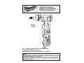 1
1
-
 2
2
-
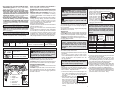 3
3
-
 4
4
-
 5
5
-
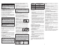 6
6
-
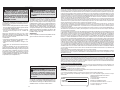 7
7
-
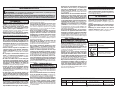 8
8
-
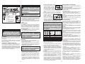 9
9
-
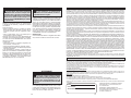 10
10
-
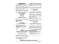 11
11
-
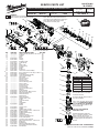 12
12
-
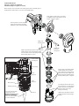 13
13
-
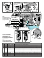 14
14


Milwaukee 2432-20 Manual de usuario
- Categoría
- Herramientas eléctricas
- Tipo
- Manual de usuario
En otros idiomas
- français: Milwaukee 2432-20 Manuel utilisateur
- English: Milwaukee 2432-20 User manual