Kobalt KMS 0724B-03 Guía del usuario
- Categoría
- Herramientas eléctricas
- Tipo
- Guía del usuario

PH18470
Questions, problems, missing parts? Before returning to your retailer, call our customer
service department at 1-888-3KOBALT (1-888-356-2258), 8 a.m. - 8 p.m., EST,
Monday - Friday.
ATTACH YOUR RECEIPT HERE
Serial Number Purchase Date
Español p. 35
ITEM # 1051232
24-VOLT
SLIDING DUAL-BEVEL
MITER SAW
MODEL # KMS 0724B-03

2
TABLE OFCONTENTS
Product Specications ......................................................................................2
Package Contents… ........................................................................................3
Safety Information… ........................................................................................4
Preparation .....................................................................................................10
Tools Needed ................................................................................................. 11
Assembly Instructions ....................................................................................12
Adjustment Instructions ..................................................................................15
Operating Instructions .................................................................................... 19
Care and Maintenance ...................................................................................32
Troubleshooting… .......................................................................................... 33
Warranty… ..................................................................................................... 34
PRODUCTS PECIFICATIONS
COMPONENT SPECIFICATIONS
Rated voltage 24V d.c.
No-load speed 5100/min. (RPM)
Blade diameter 7-1/4 in. (185mm)
Arbor size 5/8 in.
Cutting capacity
Miter at 0°/Bevel 0° - Max. Lumber size: 2-1/4in. x 9-3/8 in.
Miter at 45°/Bevel 0° - Max. Lumber size: 2-1/4in. x 6-5/8 in.
Miter at 0°/right Bevel 45° - Max. Lumber size: 3/4in. x 9-3/8 in.
Miter at 0°/left Bevel 45° - Max. Lumber size: 1-1/2in. x 9-3/8 in.
Miter at 45°/right Bevel 45° - Max. Lumber size: 3/4in. x 6-5/8 in.
Miter at 45°/left Bevel 45°- Max. Lumber size: 1-1/2in. x 6-5/8 in.
Crown Molding at 45° against fence – Max. height: 3-5/8 in.
Operating temperature 41 °F (5 °C) - 104 °F (40 °C)
Charging temperature 41 °F (5 °C) - 104 °F (40 °C)

3
PACKAGECONTENTS
Unpacking
• Carefully lift the miter saw from the carton and place it on a level worksurface.
NOTICE: This tool is heavy. To avoid back injury, lift with your legs, not your back, and get help
when needed.
• Use the main handler to lift the saw arm; do not lift the saw by the saw arm.
• This saw has been shipped with the saw arm secured in the “DOWN” position. To release
the saw arm, push down on the top of the saw arm, and pull out the arm-lockpin.
• Carefully inspect the item to ensure that no breakage or damage has occurred during
shipping. Do not discard the packing material until you have carefully inspected and
satisfactorily operated the tool
• The saw is factory set for accurate cutting. After assembly, check for accuracy as directed
in the Adjustments Instructions section of this manual. If shipping has inuenced the
settings, refer to specic adjustment procedures explained in this manual.
• If any parts are damaged or missing, please call customer service at 1-888-3 KOBALT for
assistance.
WARNING
• If any parts are missing, DO NOT attempt to assemble, install, or use the miter saw until
the missing parts have been found or replaced and the miter saw has been properly and
correctly assembled according to this manual.
A
B
C
D
E
F
PART DESCRIPTION PART DESCRIPTION
1 Miter saw 5 Carrying handle
2 Work clamp 6 Long screw, spring washer, at washer
3 Dust bag 7 Short screw, spring ser, at washer (2)
4
Double ended blade wrench
(stored in the saw)
1
2 3
6 754

4
SAFETY INFORMATION
Please read and understand this entire manual before attempting to assemble or operate
this product. If you have any questions regarding the product, please call customer service at
1-888-3KOBALT, 8 a.m. - 8 p.m., EST, Monday - Friday.
WARNING
• The operation of any power tool can result in foreign objects being thrown into your eyes,
which can result in severe eye damage. Before beginning power-tool operation, always wear
safety goggles or safety glasses with side shields and a full-face shield, when needed. We
recommend using a wide vision safety mask over eyeglasses or standard safety glasses
with shields. Always use eye protection marked to comply with ANSI Z87.1.
• Drilling, sawing, sanding or machining wood products can expose you to wood dust, a
substance known to the State of California to cause cancer. Avoid inhaling wood dust or use
a dust mask or other safeguards for personal protection.
• For more information go to: www.P65Warnings.ca.gov/wood.
• Some examples of these chemicals are:
– Lead from lead-based paints
– Crystalline silica from bricks, cement, and other masonry products
– Arsenic and chromium from chemically-treated lumber
• Your risk from these exposures varies, depending upon how often you do this type of work.
To reduce your exposure to these chemicals:
– Work in a well-ventilated area.
– Work with approved safety equipment, such as dust masks that are specially designed to
lter out microscopic particles.
– Avoid prolonged contact with dust from power sanding, sawing, grinding, drilling, and
other construction activities. Wear protective clothing and wash exposed areas with soap
and water. Allowing dust to get into your mouth or eyes or to lie on the skin may promote
absorption of harmful chemicals.
Know the Tool
To operate this tool, carefully read this manual and all labels afxed to the tool before using it.
Keep this manual available for future reference.
Important
This tool should be serviced only by a qualied service technician.
Read All Instructions Thoroughly

5
SAFETY INFORMATION
Some of the following symbols may be used on this tool. Please study them and their meaning.
Proper interpretation of these symbols will allow you to operate the tool better and more safely.
SYMBOL DEFINITION SYMBOL DEFINITION
V Volts n
0
No-load Speed
or d.c.
Direct Current RPM Revolutions per Minute
°F Degrees Fahrenheit °C Degrees Celsius
No-Hands Zone. Failure
to keep your hands away
from the blade will result
in serious personal injury.
WARNING- Always wear
eye protection
WARNING- To reduce the
risk of injury, user must
read instruction manual
A danger, warning, or
caution. It means ‘Attention!
Your safety is involved.’
General Power Tool Safety Warnings
WARNING
• Read all safety warnings, instructions, illustrations and specications provided with this
power tool. Failure to follow all instructions listed below may result in electric shock, re and/
or serious injury.
Save all warnings and instructions for future reference
The term “power tool” in the warnings refers to your mains-operated (corded) power tool or
battery-operated (cordless) power tool.
Work Area Safety
• Keep work area clean and well lit. Cluttered or dark areas invite accidents.
• Do not operate power tools in explosive atmospheres, such as in the presence of
ammable liquids, gases or dust. Power tools create sparks which may ignite the dust or
fumes.
• Keep children and bystanders away while operating a power tool. Distractions can
cause you to lose control.
Electrical Safety
• Power tool plugs must match the outlet. Never modify the plug in any way. Do not use
any adaptor plugs with earthed (grounded) power tools. Unmodied plugs and matching
outlets will reduce the risk of electric shock.
• Avoid body contact with earthed or grounded surfaces such as pipes, radiators,
ranges and refrigerators. There is an increased risk of electric shock if your body is
earthed or grounded.
• Do not expose power tools to rain or wet conditions. Water entering a power tool will
increase the risk of electric shock.

6
SAFETY INFORMATION
• Do not abuse the cord. Never use the cord for carrying, pulling or unplugging the
power tool. Keep cord away from heat, oil, sharp edges or moving parts. Damaged or
entangled cords increase the risk of electric shock.
• When operating a power tool outdoors, use an extension cord suitable for outdoor
use. Use of a cord suitable for outdoor use reduces the risk of electric shock.
• If operating a power tools in a damp location is unavoidable, use a ground fault
circuit interrupter (GFCI) protected supply. Use of a GFCI reduces the risk of electric
shock.
Personal Safety
• Stay alert, watch what you are doing and use common sense when operating a power
tool. Do not use a power tool while you are tired or under the inuence of drugs,
alcohol or medication. A moment of inattention while operating power tools may result in
serious personal injury.
• Use personal protective equipment. Always wear eye protection. Protective equipment
such as a dust mask, non-skid safety shoes, hard hat or hearing protection used for
appropriate conditions will reduce personal injuries.
• Prevent unintentional starting. Ensure the switch is in the off-position before
connecting to power source and/or battery pack, picking up or carrying the tool.
Carrying power tools with your nger on the switch or energising power tools that have the
switch on invites accidents.
• Remove any adjusting key or wrench before turning the power tool on. A wrench or a
key left attached to a rotating part of the power tool may result in personal injury.
• Do not overreach. Keep proper footing and balance at all times. This enables better
control of the power tool in unexpected situations.
• Dress properly. Do not wear loose clothing or jewellery. Keep your hair, and clothing
and gloves away from moving parts. Loose clothes, jewellery or long hair can be caught
in moving parts.
• If devices are provided for the connection of dust extraction and collection facilities,
ensure these are connected and properly used. Use of dust collection can reduce dust-
related hazards.
• Do not let familiarity gained from frequent use of tools allow you to become
complacent and ignore tool safety principles. A careless action can cause severe injury
within a fraction of a second.
Power Tool Use and Care
• Do not force the power tool. Use the correct power tool for your application. The
correct power tool will do the job better and safer at the rate for which it was designed.
• Do not use the power tool if the switch does not turn it on and off. Any power tool that
cannot be controlled with the switch is dangerous and must be repaired.
• Disconnect the plug from the power source and/or remove the battery pack,
if detachable, from the power tool before making any adjustments, changing
accessories, or storing power tools. Such preventive safety measures reduce the risk of
starting the power tool accidentally.
• Store idle power tools out of the reach of children and do not allow persons
unfamiliar with the power tool or these instructions to operate the power tool. Power
tools are dangerous in the hands of untrained users.
• Maintain power tools and accessories. Check for misalignment or binding of moving parts,
breakage of parts and any other condition that may affect the power tool’s operation. If
damaged, have the power tool repaired before use. Many accidents are caused by poorly
maintained power tools.

7
SAFETY INFORMATION
• Keep cutting tools sharp and clean. Properly maintained cutting tools with sharp cutting
edges are less likely to bind and are easier to control.
• Use the power tool, accessories and tool bits etc. in accordance with these
instructions, taking into account the working conditions and the work to be
performed. Use of the power tool for operations different from those intended could result in
a hazardous situation.
• Keep handles and grasping surfaces dry, clean and free from oil and grease. Slippery
handles and grasping surfaces do not allow for safe handling and control of the tool in
unexpected situations.
Battery Tool Use and Care
• Recharge only with the charger specied by the manufacturer. A charger that is suitable
for one type of battery pack may create a risk of re when used with another battery pack.
• Use power tools only with specically designated battery packs. Use of any other
battery packs may create a risk of injury and re.
Battery charger Battery packs
KRC 2445-03; KRC 2490-03; KB 124-03; KB 224-03; KB 424-03;
KB 524-03; KB 624-03; KB 924-03
• When battery pack is not in use, keep it away from other metal objects, like paper clips,
coins, keys, nails, screws or other small metal objects, that can make a connection
from one terminal to another. Shorting the battery terminals together may cause burns or
a re.
• Under abusive conditions, liquid may be ejected from the battery; avoid contact. If
contact accidentally occurs, ush with water. If liquid contacts eyes, additionally seek
medical help. Liquid ejected from the battery may cause irritation or burns.
• Do not use a battery pack or tool that is damaged or modied. Damaged or modied
batteries may exhibit unpredictable behavior resulting in re, explosion or risk of injury.
• Do not expose a battery pack or tool to re or excessive temperature. Exposure to re or
temperature above 130 °C may cause explosion.
• Follow all charging instructions and do not charge the battery pack or tool outside the
temperature range specied in the instructions. Charging improperly or at temperatures
outside the specied range may damage the battery and increase the risk of re.
Service
• Have your power tool serviced by a qualied repair person using only identical
replacement parts.This will ensure that the safety of the power tool is maintained.
• Never service damaged battery packs. Service of battery packs should only be performed
by the manufacturer or authorized service providers.
Specic Safety Warnings for Miter Saw
• Miter saws are intended to cut wood or wood-like products, they cannot be used
with abrasive cut-off wheels for cutting ferrous material such as bars, rods, suds, etc.
abrasive dust causes moving parts such as the lower guard to jam. Sparks form abrasive
cutting will burn the lower guard, the kerf insert and other plastic parts.
• Use clamps to support the workpiece whenever possible. If supporting the workpiece
by hand you must always keep your hand at least 100 mm from either side of the saw
blade. Do not use this saw to cut pieces that are too small to be securely clamped or
held by hand. If your hand is placed too close to the saw blade, there is an increased risk of
injury from blade contact.

8
SAFETY INFORMATION
• The workpiece must be stationary and clamped or held against both the fence and
the table. Do not feed the workpiece into the blade or cut “freehand” in any way.
Unrestrained or moving workpieces could be thrown at high speeds, causing injury.
• Push the saw through the workpiece. Do not pull the saw through the workpiece. To
make a cut, raise the saw head and pull it out over the workpiece without cutting,
start the motor, press the saw head down and push the saw through the workpiece.
Cutting on the pull stroke is likely to cause the saw blade to climb on top of the workpiece
and violently throw the blade assembly towards the operator.
• Never cross your hand over the intended line of cutting either in front or behind the
saw blade. Supporting the workpiece “cross handed” i.e. holding the workpiece to the right
of the saw blade with your left hand or vice versa is very dangerous.
• Do not reach behind the fence with either hand closer than 100 mm from either side
of the saw blade, to remove wood scraps, or for any other reason while the blade is
spinning. The proximity of the spinning saw blade to your hand may not be obvious and
you may be seriously injured.
• Inspect your workpiece before cutting. If the workpiece is bowed or warped, clamp it
with the outside bowed face toward the fence. Always make certain that there is no
gap between the workpiece, fence and table along the line of the cut. Bent or warped
workpieces can twist or shift and may cause binding on the spinning saw blade while
cutting. There should be no nails or foreign objects in the workpiece.
• Do not use the saw until the table is clear of all tools, wood scraps, etc., except for
the workpiece. Small debris or loose pieces of wood or other objects that contact the
revolving blade can be thrown with high speed.
• Cut only one workpiece at a time. Stacked multiple workpieces cannot be adequately
clamped or braced and may bind on the blade or shift during cutting.
• Ensure the miter saw is mounted or placed on a level, rm work surface before use. A
level and rm work surface reduces the risk of the miter saw becoming unstable.
• Plan your work. Every time you change the bevel or miter angle setting, make sure
the adjustable fence is set correctly to support the workpiece and will not interfere
with the blade or the guarding system. Without turning the tool “ON” and with no
workpiece on the table, move the saw blade through a complete simulated cut to assure
there will be no interference or danger of cutting the fence.
• Provide adequate support such as table extensions, saw horses, etc. for a workpiece
that is wider or longer than the table top. Workpieces longer or wider than the miter saw
table can tip if not securely supported. If the cut-off piece or workpiece tips, it can lift the
lower guard or be thrown by the spinning blade.
• Do not use another person as a substitute for a table extension or as additional
support. Unstable support for the workpiece can cause the blade to bind or the workpiece to
shift during the cutting operation pulling you and the helper into the spinning blade.
• The cut-off piece must not be jammed or pressed by and means against the spinning
saw blade. If conned, i.e. using length stops, the cut-off piece could get wedged against the
blade and thrown violently.
• Always use a clamp or a xture designed to properly support round material such as
rods or tubing. Rods have a tendency to roll while being cut, causing the blade to “bite”
and pull the work with your hand into the blade.
• Let the blade reach full speed before contacting the workpiece. This will reduce the risk
of the workpiece being thrown.
• If the workpiece or blade becomes jammed, turn the miter saw off. Wait for all moving
parts to stop and disconnect the plug form the power source and/or remove the
battery pack. Then work to free the jammed material. Continued sawing with a jammed
workpiece could cause loss of control or damage to the miter saw.

9
SAFETY INFORMATION
• After nishing the cut, release the switch, hold the saw head down and wait for the
blade to stop before removing the cut-off piece. Reaching with your hand near the
coasting blade is dangerous.
• Hold the handle rmly when making an incomplete cut or when releasing the switch
before the saw head is completely in the down position. The braking action of the saw
may cause the saw head to be suddenly pulled downward, causing a risk of injury.
Additional Safety Warnings for Miter Saw
WARNING
• The use of this tool can generate and/or disburse dust, which may cause serious and
permanent respiratory or other injury. Always use protection appropriate for the dust
exposure. Direct particles away from the face and body.
• Know your power tool. Read the Operator’s Manual carefully. Learn the applications
and limitations, as well as the specic potential hazards related to this tool. Following this
rule will reduce the risk of electric shock, re or serious injury.
• Before beginning power tool operation, always wear safety goggles or safety glasses
with a side shield and a full face shield when needed. We recommend a Wide Vision
Safety Mask for use over eyeglasses or standard safety glasses with side shields. Always
use eye protection which is marked to comply with ANSI Z87.1.
• Only use recommended saw blades with specied size and arbor.
• Do not use with any abrasive wheels.
• Protect your lungs. Wear a face mask or a dust mask if the operation is dusty.
• Protect your hearing. Wear appropriate personal hearing protection during use. Under
some conditions and duration of use, noise from this product may contribute to hearing loss.
• All visitors and bystanders must wear the same safety equipment that the operator of the
saw wears.
• Always check the tool for damaged parts. Before further use of the tool, a guard or
other part that is damaged should be carefully checked to determine whether it will operate
properly and perform its intended function. Check for misalignment or binding of moving
parts, broken parts, and any other condition that may affect the tool’s operation. A guard or
other part that is damaged should be properly repaired or replaced by a qualied person.
• Save these instructions. Refer to them frequently and use them to instruct others who may
use this tool. If someone borrows this tool, make sure they have these instructions also.

10
PREPARATION
Know Your Miter Saw
This miter saw can be used for the purpose listed: cross cutting wood products and plastic;
bevel cutting and compound cutting wood products and plastics .
The safe use of this product requires an understanding of the information on the tool and in this
operator’s manual, as well as knowledge of the project you are attempting. Before attempting
to use the saw, familiarize yourself with all of its operating features and safety requirements.
I
H
G F E D
C
B
A
Q
P
Z
Y
V
U
T
S
R
X
W
AD
AC
AB
AA
N
M
L
K
J
O

11
PREPARATION
PART DESCRIPTION PART DESCRIPTION
A Lock-off buttons
P Miter-control lever
B On/Off switch
Q Lower blade guard
C LED switch
R Main handle
D Upper blade guard
S Spindle-lock button
E Dust-extraction port
T Fixed fence
F Depth-control knob
U Sliding fence (left and right)
G Bevel-angle indicator
V Fence-lock knob (left and right)
H Bevel scale
W Clamp receptacle (left and right)
I Bevel-change lever
X 45° bevel stop
J Mounting holes (8)
Y 33.9° bevel stop
K Saw base
Z Bevel-stop bolt
L Miter table
AA Bevel-lock knob
M Miter scale
AB Sliding-lock knob
N Miter-angle indicator
AC Arm-lock pin
O Saw blade
AD Carrying handle
WARNING
• Do not allow familiarity with the miter saw to cause carelessness. Remember that one
careless moment is enough to cause severe injury. Before attempting to use any tool, be
sure to become familiar with all of the operating features and safety instructions.
• Do not attempt to modify this tool or create accessories not recommended for use with this
tool. Any such alteration or modication is misuse and could result in a hazardous condition
leading to possible serious personal injury.
• Use only a saw blade diameter in accordance with the markings on the saw and information
about the bore diameter and the maximum kerf of the saw blade. Use only saw blades that
are marked with a speed equal or higher than the speed marked on the tool.
TOOLS NEEDED
The following tools (not included) are needed for making adjustments or installation.
2.5mm wrench 3mm wrench
Phillips Screwdriver
Adjustable Wrench
Combination square

12
ASSEMBLY INSTRUCTIONS
This product requires assembly.
WARNING
• If any parts are damaged or missing, do not operate this tool until the missing parts are
replaced. Failure to heed this warning could result in serious personal injury.
• Always make sure that the miter saw is securely mounted to a workbench or an approved
work stand. Failure to heed this warning can result in serious personal injury.
• Battery tools are always in operating condition. Therefore, ALWAYS remove the battery
pack from tool before making any adjustments or installing accessories. Failure to heed this
warning could result in accidental starting, which can cause serious personal injury.
1. Mounting Holes
The miter saw should be mounted to a rm
supporting surface, such as a workbench. Four
large bolt holes have been provided in the saw
base for this purpose.
Each of the four large mounting holes (J) should
be bolted securely using M10 machine bolts, lock
washers, and hex nuts (not included). Bolts should
be of sufcient length to accommodate the saw
base, lock washers, hex nuts, and the thickness of
the workbench.
Tighten all four bolts securely.
The other smaller mounting holes are for use with
nails or screws. The nails or screws should have
sufcient length to secure the saw.
The hole pattern for mounting to a workbench is shown in Fig. 1. Carefully check the
workbench after mounting to make sure that no movement can occur during use. If any tipping,
sliding, or walking is noted, secure the workbench to the oor before operating.
NOTE: Many of the illustrations in this manual show portions of the miter saw. This is
intentional so that we can clearly show points being made in the illustrations. Never operate
the saw without all guards securely in place and in good operating condition.
1
Mounting
Holes
Mounting
Holes

13
ASSEMBLY INSTRUCTIONS
2. Carrying Handle
a. Align the holes on the saw arm with the holes
in the carrying handle (AD), then install the
carrying handle onto the arm.
b. Insert the long screw with the spring washer
and at washer (6) into the hole in the carrying
handle. Tighten the long screw it with the
double ended wrench (4).
c. Insert the two short screws with the spring
washers and at washers (7) into the holes in
the carrying handle. The two short screws with
the double ended wrench.
3. Dust-extraction Port
This miter saw comes with a dust bag (3) to help
you keep the work area clean. The dust bag is ideal
for smaller jobs. The dust-extraction port (E) also
accepts a standard 1-1/2 in. (38cm) vacuum hose
for dust collection.
4. Work Clamp
WARNING
• In some operations, the work clamp (2) may
interfere with the operation of the lower blade
guard (Q). To reduce the risk of serious personal
injury, always make sure that there is no
interference with the lower blade guard prior to
beginning any cutting operation.
a. Insert the work clamp into one of the two clamp
receptacles (W) in the base behind the fence.
b. Rotate the knob on the work clamp to move it
up or down as needed.
When cutting wide work pieces (such as nominal
2x8 boards), the boards must be clamped with
the work clamp provided or with a C-clamp (not
included).
WARNING
• When using the work clamp included or a
C-clamp (not included) to secure the work piece,
clamp the work piece on one side of the blade
only. The work piece must remain unclamped on
the other side of the blade to prevent the blade
from binding in the work piece. The work piece binding the blade will cause the motor to stall
and cause kickback, resulting in possibly serious injury.
2
3
E
3
4
2
W
Q
6 7
AD

14
ASSEMBLY INSTRUCTIONS
5. Locking/Unlocking the Saw Arm
When locking and unlocking the saw arm, it is not
necessary to loosen the depth-control knob.
To unlock and raise the saw arm:
a. Firmly grasp the main handle (R) and apply
downward pressure while at the same time
pulling the arm-lock pin (AC) out and away
from the saw housing.
b. Release the arm-lock pin and slowly raise the
saw arm.
To lock the saw arm:
a. Firmly grasp the main handle (R) and apply
downward pressure until head stops.
b. Push in the arm-lock pin (AC) toward the saw, allowing it to lock the saw into place.
NOTE: Do not use saw to cut while it is in the locked position.
5
R
AC

15
6b
MN
ADJUSTMENT INSTRUCTIONS
The miter saw is properly set and adjusted prior to shipping. The adjustments were made at
the factory and normally do not require re-adjustment.
If, in the course of use, adjustments are required, please follow the directions below.
WARNING
• Battery tools are always in operating condition. Therefore, always remove the battery pack
from the tool before making any adjustments or installing accessories, failure to do could
result in accidental starting causing serious injury.
6. Squaring the Blade to the Fence
a. Remove the battery pack from the tool.
b. Lower the saw arm all the way and engage
the arm-lock pin (AC) to hold the saw arm in
“DOWN” position.
c. Set the bevel and miter angles to 0°.
d. Place the heel of a combination square (not
included) against the blade (O) and the rule of
the square against the xed fence (T).
NOTE: Be sure to rest the square against the body
of the blade, and not against the teeth of the blade.
e. If the blade is not 90° to the fence, adjustments
are needed。
f. Lift the miter-control lever (P) to unlock the miter
table (L).
g. Hold the miter-control lever to rotate the miter
table until the miter-angle indicator (N) is at
approximately left 30° position on the miter
scale (M).
h. Loosen the three screws that hold the miter
scale in place.
i. Lift the miter-control lever to rotate the miter
table to the 0° position on the miter scale or
until the detent engages in the miter-scale
detent plate.
j. Adjust the miter angle until the blade is ush
with the square.
k. Press the miter-control lever down to lock the
turn table.
l. Tighten the two visible screws that secure the miter scale.
m. Lift the miter-control lever to rotate the miter table until the pointer is at approximately left
30° position on the miter scale.
n. Tighten the remaining screw to secure the miter scale detent plate.
NOTE: If the saw has not been used recently, verify that the blade is square to the fence, and
readjust if necessary.
6a
L
T
P
combination
square
O

16
ADJUSTMENT INSTRUCTIONS
7. Miter-Angle Indicator Adjustment
a. Remove the battery from the tool.
b. Square the blade to the fence, to make sure
that the blade is 90° to the fence and the miter-
detent locking system is engaged. Press the
miter-control lever (P) to lock the miter angle.
c. Loosen the miter-angle indicator screw and
adjust the miter-angle indicator (N) to the “0”
mark on the miter scale (M).
d. Tighten the miter-angle indicator screw.
8. Squaring the Blade to the Table
a. Remove the battery pack from the tool.
b. Lower the saw arm all the way and hold it down
while pushing the arm-lock pin (AC) to lock the
saw arm in the “DOWN” position.
c. Set the bevel and miter angles to 0°.
d. Place a combination square on the miter table
(L) with the rule against the table and the heel
of the square against the saw blade (O).
NOTE: Be sure to rest the square against the body
of the blade, and not against the teeth of the blade.
e. If the blade is not 90° to the table, loosen the
bevel-lock knob to unlock the bevel.
f. With a 3mm hex wrench (not included), adjust
the inner screw in or out until the leg of the
square is ush with the saw blade.
g. Once the angle is set, retighten the bevel-lock
knob. Recheck the blade-to-table alignment.
8a
7
M N
P
screw
8b
inner screw
O
L

17
ADJUSTMENT INSTRUCTIONS
9. Bevel-Angle Indicator Adjustment
a. Remove the battery pack from the tool.
b. Square the blade to the table to make sure that
the blade is 90° to the table.
c. Rotate the bevel-lock knob to lock the bevel.
d. Check to see if the bevel-angle indicator (G) is
pointing to 0° on the bevel scale (H).
e. If the indicator is not pointing to 0°, loosen the
bevel-angle indicator screw, adjust the indicator
to 0° on bevel scale and then retighten the
screw.
10. Adjusting the Blade to the Miter Table 45°
Bevel, 0° Miter
a. Remove the battery pack from the tool.
b. Loosen the bevel-lock knob (AA) to release the
bevel. Move the left sliding fence (U) all the way
out along the horizontal direction.
c. Pull the 45° stop block (X) toward the rear of the
saw.
d. Tilt the saw head to set the bevel-angle to 45°.
NOTE: To obtain correct bevel angles, rotate the
bevel-stop lever (I) to the other side to pull it out, and
tilt the saw head to the desired angle.
e. Place a combination square (not included) on
the miter table with the rule against the table and
the heel of the square against the saw blade (O).
NOTE: Be sure to rest the square against the body of the blade, and not against the teeth of
the blade.
f. If the blade is not 45° to the miter table, adjust by tightening or loosening the bevel-stop
bolt (Z) on the tool with a 6mm hex key (not included).
g. Retighten the bevel-lock knob and push the bevel-stop pin in. Recheck the blade-to-table
alignment.
9
G
H
screw
10
I
Z X Y

18
ADJUSTMENT INSTRUCTIONS
11. Miter-control Lever Adjustment
NOTE: This adjustment was made at the factory
and, under normal circumstances, it does not require
re-adjustment.
In the lock position, the miter-control lever (P) should
feel tight and secure and considerable effort should
be required to move the miter table. If the miter-
control lever feels loose or the table moves easily
when in the locked position, and adjustment to the
miter-control lever is required.
To adjust
a. Remove the battery pack from the saw.
b. Lift the miter-control lever (P).
c. Remove the screws securing the throat plates,
and remove both throat plates and set aside.
d. Locate the lock nut.
e. Using a 2.5mm wrench (not included), insert into the hole in the lock nut, adjust the lock
nut by turning it counterclockwise to tighten the miter-control lever or turning it clockwise to
loosen the miter-control lever until the proper amount of tension in the miter-control lever is
attained.
NOTE: it may be necessary to lock and unlock the miter-control lever to determine the proper tension.
f. Once the adjustment is complete, reinstall both throat plates. Be careful not to over
tighten,which can cause the throat plate to bow or bend.
g. Press the miter-control lever down to lock the miter table in place.
WARNING
• Never operate the saw without the throat plate installed.
12. Pivot Adjustments
NOTE: These adjustments were made at the factory and, under normal circumstances, they do
not require re-adjustment.
Saw-arm Travel Pivot Adjustment:
The saw arm should automatically rise (travel) completely to the full “UP” position by itself after
the arm-lock pin (AC) is released.
WARNING
• To avoid risk of personal injury, if your saw arm does not rise by itself, or if there is play in
the pivot joints, have your saw serviced by a qualied service technician before using.
Bevel-Pivot Adjustment:
Your miter saw arm should bevel smoothly by lifting the bevel-lock lever up to unlock the bevel
and tilting the saw arm to the left or right.
WARNING
• To avoid risk of personal injury, have your saw serviced by a qualied service person before
using if movement is tight or if there is play in the bevel pivot.
11
Lock nut
Throat plates
P

19
OPERATING INSTRUCTIONS
When transporting the saw, turn off the saw and remove the battery pack from the miter saw,
then lower the saw arm and lock it in the “DOWN” position. Lock the saw arm by depressing
the arm-lock pin (AC). A carrying handle (AD) is located on the top of the saw arm. Never lift
the saw by the main handle on the front end of the saw arm or by the fence.
Always maintain a speed and pressure that will allow cutting without overheating the saw
blade. Applying too much pressure will overheat the saw and melt the plastic. Do not force the
saw, let the tool do the work.
WARNING
• To reduce the risk of injury, wear safety goggles or glasses with side shields.
• Before each use, verify that the blade is free of cracks, loose teeth, missing teeth, or any
other damage. Do not use if damage is observed or suspected.
• Do not start the miter saw without checking for interference between the blade and the miter
fence. Damage could result to the blade if it strikes the miter fence during operation of the saw.
• Always wait for the blade to stop completely, and remove the battery pack from the miter
saw before changing accessories or making adjustments.
13. To Install/Remove Battery Pack
To Attach Battery Pack
a. Make sure that the On/Off switch (B) is in the
OFF position.
b. Align the raised portion on the battery pack with
the grooves on the bottom of the tool, and then
slide the battery pack onto the tool as shown.
c. Ensure that the battery-release buttons on the
battery pack snap into place and the battery
pack is secured to the tool before beginning
operation.
NOTICE: When placing the battery pack on the tool,
be sure that the raised rib on the battery pack aligns
with the groove on the tool and the latches snap into place properly. Improper assembly of the
battery pack can cause damage to internal components.
To Detach Battery Pack
a. Make sure that the On/Off switch (B) is in the OFF position.
b. Press the battery-release buttons to release the battery pack.
c. Pull backward on the battery pack to remove it from the tool.
WARNING
• Battery tools are always in operating condition. Therefore, always remove the battery pack
from the tool when the tool is not in use or when carrying the tool.
13
Battery-release
button

20
OPERATING INSTRUCTIONS
14. Blade Change
To Remove the Blade
WARNING
• Use protective gloves when removing or installing
the blade. Do not touch the blade teeth to avoid
injury.
a. Remove the battery pack from the saw.
b. Raise the saw arm.
c. Lift and hold the lower blade guard (Q); loosen
the screw xed on the blade-bolt screw guard
with the double ended wrench (4).
d. Rotate the blade-bolt guard to expose the blade
bolt.
e. Press and hold the spindle-lock button (S), and
rotate the saw blade (O) at the same time until it locks into position.
f.
Use the double ended blade wrench (4) to turn the blade bolt clockwise. Remove the blade
bolt.
g. Remove the outer ange and the blade. Wipe the blade anges and spindle to remove any
dust and debris.
To Install the Blade
a. Remove the battery pack from the saw.
b. Ensure that the inner ange is properly installed in the spindle.
c. Match the arrow on the saw blade (O) with the arrow on the upper blade guard (D). Make
sure that the teeth of the blade are pointing downward.
d. Fit the saw blade inside the blade guard and onto the spindle.
e. Install the outer ange.
WARNING
• Make sure that the at side of the outer ange is placed against the blade.
f. Press and hold the spindle-lock button (S), and use the double ended wrench (4) to turn
the blade bolt counter-clockwise until the lock engages. Securely tighten the blade bolt.
g. Rotate the blade-bolt guard into position, and use the double ended wrench to securely
tighten the screw by turning it clockwise. Store the double ended wrench safely: wrench
storage is provided in the miter saw base.
h. Make sure that the spindle-lock button is released so the blade will rotate freely.
i. Lower the saw arm, and check the clearance between the blade and the miter table. The
blade should rotate freely.
Blade Guard System
The lower blade guard (Q) on the saw is there for the operator’s protection and safety. Do not
alter it for any reason.
WARNING
• To avoid possible serious injury, never use the saw when the lower blade guard is not
operating correctly.
• Check the lower blade guard for correct operation before each use, it should move freely
and instantly returns to the closed position. If the lower blade guard does not snap closed at
any time, take it to a qualied service technician for repair.
14
4
O
blade
bolt
outer
ang
blade-
bolt
guard
screw
S

21
OPERATING INSTRUCTIONS
15. Sliding Fence
CAUTION
• Adjust and fasten the fences properly before
cutting.
The sliding fences (U) are adjustable to
accommodate different sized work pieces. Loosen
the fence-lock knobs (V) on the sliding fences away
from the blade to make sure that the blade can not
contact the fence.
When making a crosscut or a miter cut, move the
sliding fences closer to the blade to better support
the work piece. When making a bevel cut, move
fences away from the blade to make sure that the
blade can not contact the fence.
16. Setting Cutting-Depth
When used, the depth-control knob limits the
downward travel of the saw blade when cutting
dadoes and other non-through cuts.
To use the depth guide
a. Remove the battery pack from the saw.
b. With the bottom of the depth-control knob (F)
touching the depth stop, adjust the depth-
control knob by turning it until the desired depth
of cut is attained.
c. A wooden spacer must be placed between the
workpiece and the fence to create a distance
of 3-1/2 inches between the workpiece and
the fence for a consistent depth of cut in the
workpiece. Use the work clamp to clamp the
spacer and use another suitable clamp to clamp
the workpiece. Make the slide cut at the desired
depth.
17. LED Work Light
The LED lighting system casts a shadow of the
blade onto the workpiece. This results in greater
accuracy of cuts and requires no adjustments.
To turn on the LED, press the LED switch (C).
The LED work light will automatically turn off after
approximately 15 seconds after the On/Off switch
(B) is released.
NOTE: The LED work light will automatically turn on
when the On/Off switch is depressed.
Bring the saw arm down so that the blade is approximately 1/4 in. from the workpiece. The
shadow of the blade will be projected onto the workpiece, indicating where the blade teeth will
make contact as the cut is made. Follow all of the cutting instructions for the type of cut to be
performed.
17
C
shadow of
blade teeth
15
V
U
16
F
depth
stop

22
OPERATING INSTRUCTIONS
18. ON/OFF Switch
For safety, the On/Off switch (B) is designed to
prevent accidental starts.
a. To operate the saw, press the lock-off button (A)
to disengage the lock, then squeeze the On/Off
switch.
WARNING
• The blade should reach full speed before it
contacts the work piece.
b. To turn off the saw, release the On/Off switch,
and allow the blade to come to a complete stop.
WARNING!
• Make the On/Off trigger switch childproof. Insert a small padlock or cable (not included)
through the hole in the On/Off switch, locking the switch and preventing children or other
unauthorized users from turning on the saw.
19. Chop Cuts
Chop cuts are used mainly for narrow pieces.
a. Remove the battery pack from the saw.
b. Turn the sliding-lock knob (AB)
counterclockwise to release the slide rail.
c. Slide the saw arm to the rear as far as it will go.
d. Tighten the sliding-lock knob.
e. Properly position the work piece. Make sure
that the work piece is clamped rmly against
the table and the fence. Make sure that the
work clamp (2) does not interfere with the
cutting operation.
f. Attach the battery to the saw.
g. Before turning the saw on, lower the saw arm
to make sure that the clamp clears the lower
guard and the saw arm.
WARNING
• Use a clamping position that does not interfere with the cutting operation.
h. Turn on the saw. Always allow the blade to reach full speed before cutting. Lower the saw
arm and make your cut.
i. Wait until blade comes to a complete stop before returning the saw arm to the raised
position and/or removing the work piece.
18
B A
hole
19
2

23
OPERATING INSTRUCTION
20. Slide Cuts
This type of cut is used mainly for wide pieces.
Loosen the sliding-lock knob (AB), then pull the saw
arm towards the operator. Lower the saw arm into
the work piece and then push it to the rear of the saw
to make the cut.
WARNING
• Never pull the saw toward you during a cut. The
blade can suddenly climb up on top of the work
piece and force itself toward you.
• Follow these instructions for making your slide cut:
a. Remove the battery pack from the saw.
b. Properly position the work piece. Make sure the
work piece is clamped rmly against the table
and thefence.
c. Loosen the sliding-lock knob (AB).
d. Attach the battery pak to the saw.
e. Grasp the main handle (R) and pull the saw arm away from the fence until the blade clears
the front of the work piece, or to its maximum extension.
f. Before turning the saw on, lower the saw arm to make sure the clamp clears the lower guard
and saw arm.
WARNING
• Use a clamping position that does not interfere with the cutting operation.
g. Turn on the on/off switch (B) Always allow the blade to reach full speed before cutting.
h. Lower the saw arm all the way down, and cut through the edge of the work piece.
i. Push (but do not force) the saw arm toward the fence all the way to the rear position to
complete the cut.
j. Release the On/Off switch. Wait until the blade comes to a complete stop before returning
the saw arm to the raised position, then removethe work piece.
21. Crosscutting
A crosscut is a cut made across the grain of the work piece. A straight crosscut is a cut made
with the miter table set at the 0° position. Miter crosscuts are made with the miter table set at
an angle other than 0°, either left or right.
a. Remove the battery pack from the saw.
b. Mark the cutting line on the work piece with a pencil.
c. Push in the arm-lock pin (AC) to lock the saw arm in the “DOWN” position.
d. Loosen the miter-control lever (P), and turn miter-control lever to the right side.
e. Move the saw to the desired angle, using either the miter-detent or the miter scale. Quickly
locate 0°, 15°, 22.5°, 31.6°, and 45° left or right by noting the stops or clicks at these angle
settings.
f. Retighten the miter-control lever (P)
NOTE: With the miter-control lever lifted (and held), the miter table moves freely to any desired
angle. Alternately, lift the miter-control lever and move the table until it is close to the desired
position, release the miter-control lever, and move the next detent. The miter table will stop at
each index point on the miter scale.
20

24
OPERATING INSTRUCTIONS
g. Attach the battery pack to the saw.
h. Pull out the arm-lock pin to release the saw arm.
i. Place the work piece at on the miter table with
one edge securely against the fence. If the
board is warped, place the convex side against
the fence. If the concave edge of the board is
against the fence, the board could collapse on
the table at the end of the cut and jam the blade
(see Cutting Warped Material).
j. Turn on the LED light switch (C) and align the
pencil line with the blade’s shadow line.
k. Use the work clamp (2) to secure the work piece
against the saw table and fence.
l. When cutting a long work piece, use a block
(not supplied) to support the work piece.
WARNING
• To avoid serious personal injury, always securely
tighten the miter-control lever before making a
cut. Failure to do so could result in movement of
the control arm or miter table while making a cut.
• Never use another person as an additional
support for a work piece that is longer or wider
than the basic saw table, or to help feed, support,
or pull the work piece.
• To avoid serious personal injury, always keep
hands outside of the “No-Hands Zone”, as
marked on the saw base, or at least 3” (7.6 cm)
away from the blade. Never perform any cutting
operation “freehand” (i.e., without holding the
work piece against the fence), because the blade
could grab the work piece, causing it to slip and twist.
m. Before turning on the saw, perform a test of the cutting operation by lowering the saw arm
to make sure that no problems will occur when the cut is made.
n. Hold the main handle (R) and turn the saw on with the ON/Off switch (B). Allow several
seconds for the blade to reach maximum speed before cutting.
o. Slowly lower the blade into and through the work piece. Complete the cut.
p. Release the On/Off switch. Allow the saw blade to stop rotating before raising the blade out
of the work piece.
21a
straight crosscut
2
P
21b
miter crosscut
2
P

25
OPERATING INSTRUCTIONS
22. Bevel Cutting
A bevel cut is a cut made across the grain of the
work piece with the blade at an angle other than
90° to the miter table and the work piece. A straight
bevel cut is made with the miter table set at the 0°
position and with the saw head set at a bevel angle
between 0° and 48° left, or 0° and 46° right.
a. Remove the battery pack from the saw.
b. Mark the cutting line on the work piece with a
pencil.
c. Make sure that the miter table is positioned at
0° and locked with the miter-control lever (P).
WARNING
• To avoid serious personal injury, always rotate
the bevel-lock knob (AA) to securely tighten it before making a cut. Failure to do so could
result in movement of the control arm or the miter table while making a cut.
d. Pull out the arm-lock pin (AC) to release the saw arm.
e. Release the bevel-lock knob (AA) and tilt the saw arm to the desired bevel angle as
indicated on the bevel scale. The blade can be positioned at any angle from a 90° straight
cut (0° on the scale) to a 46° right or a 48° left bevel.
NOTE: To obtain correct bevel angles, rotate the bevel-stop lever (I) to the other side to pull it
out, and tilt the saw to the desired angle.
NOTE: Use the bevel stop (W, Y) to quickly locate 33.9° and 45° bevel angles.
f. Rotate the bevel-lock knob to securely tighten it.
WARNING
• Loosen the sliding fence, and position the fence so that it will not interfere with the saw
assembly during the cut, and then re-tighten the fence.
g. Attach the battery pack to the saw.
h. Place the work piece at on the miter table, with one edge securely against the fence. If
the board is warped, place the convex side against the fence. If the concave edge of the
board is against the fence, the board could collapse on the blade at the end of the cut and
jam the blade (see Cutting Warped Material).
i. Turn on the LED light switch and align the pencil line aligned with the blade’s shadow line.
j. Use the work clamp (2) to secure the work piece against the miter saw table and fence.
k. When cutting a long work piece, use a block (not supplied) to support the long work piece.
WARNING
• Never use another person as an additional support for a work piece that is longer or wider
than the basic saw table, or to help feed, support, or pull the work piece.
• To avoid serious personal injury, always keep hands outside the “No-Hands Zone,” as
marked on the saw base, or at least 3” (7.6 cm) away from the blade. Also, never perform
any cutting operation “freehand” (i.e., without holding the work piece against the fence),
because the blade could grab the work piece, causing it to slip and twist.
22
R
2
P

26
OPERATING INSTRUCTIONS
l. Before turning the saw on, perform a trial of the cutting operation by lowering the saw arm
to make sure that no problems will occur when the cut is made.
m. Hold the main handle (R), and use the On/Off switch (B) to turn the saw on. Allow several
seconds for the blade to reach maximum speed before cutting.
n. Slowly lower the blade into and through the work piece.
o. Release the On/Off switch. Allow the saw blade to stop rotating before raising the blade out
of the work piece.
CAUTION
• Always perform a “dry-run” cut to determine whether the operation being attempted is
possible before power is applied to the miter saw.
23. Compound Miter Cutting
WARNING
• When making a cut with a bevel angle, slide the
upper sliding fence (U) out of the cutting path.
A compound miter cut is a cut made using a miter
angle and a bevel angle at the same time. This
type of cut is used for decorative moldings, picture
frames, and other ne joinery. To make this type of
cut, the miter table must be rotated to the correct
miter angle and the saw arm must be tilted to the
correct bevel angle.
Always take special care when making compound
miter cuts, due to the interaction of the two angle
settings. Adjustments of miter and bevel settings are
interdependent. When the miter setting is adjusted, the effect of the bevel setting also changes.
When the bevel setting is adjusted, the effect of the miter setting is changed. It may take several
settings and trial cuts to obtain the desired cut. The rst angle setting should be checked
after setting the second angle, because adjusting the second angle affects the rst. Once the
two correct settings for a particular cut have been obtained, always make a test cut in scrap
material before making a nish cut in good material.
a. Remove the battery pack from the saw.
b. Mark the cutting line on the work piece with a pencil.
c. Pull out the arm-lock pin AC) to release the saw arm.
d. Loosen the miter-control lever (P) and rotate the miter table to the desired miter angle.
e. Quickly locate 0°, 15°, 22.5°, 31.6° and 45°left with right by the miter detents, or manually
lock the adjustment at other angle settings.
f. When the desired miter table setting is achieved, tighten the miter-control lever.
WARNING
• To avoid serious personal injury, always securely tighten the miter-control lever before
making a cut. Failure to do so could result in movement of the control arm or miter table
while making a cut.
g. To set the bevel angle, rotate the bevel-lock knob (AA) to unlock the bevel and tilt the saw
arm to the desired bevel angle, as shown on the bevel scale. Bevel angles can be set from
0° to 48° left and 0° to 46° right.
23

27
OPERATING INSTRUCTIONS
NOTE: To obtain correct bevel angles, rotate the bevel-stop lever (I) to the other side to pull it
out, and tilt the saw to the desired angle.
h. When the saw arm has been set at the desired angle, rotate the bevel-lock knob to
securely tighten it.
i. Connect the saw with the battery pack.
j. Place the work piece at on the miter table, with one edge securely against the fence. If
the board is warped, place the convex side against the fence. If the concave edge of the
board is against the fence, the board could collapse on the blade at the end of the cut and
jam the blade.
k. Turn on the LED light switch (C) and align the pencil line aligned with the blade’s shadow
line.
l. Use the work clamp (2) to secure the work piece against the saw table and fence.
m. When cutting a long work piece, use a block (not supplied) to support the long work piece.
WARNING
• Never use another person as an additional support for a work piece that is longer or wider
than the basic saw table, or to help feed, support, or pull the work piece.
• To avoid serious personal injury, always keep hands outside the “No-Hands Zone,” as
marked on the saw base, or at least 3” (7.6 cm) away from the blade. Also, never perform
any cutting operation “freehand” (i.e., without holding the work piece against the fence),
because the blade could grab the work piece, causing it to slip and twist.
n. Before turning the saw on, perform a trial of the cutting operation by lowering the saw arm
to make sure that no problems will occur when the cut is made.
o. Hold the saw arm and turn the saw on with the on/Off switch (B). Allow several seconds
for the blade to reach maximum speed before cutting.
p. Slowly lower the blade into and through the work piece.
q. Release the lock-off button and the On/Off switch. Allow the saw blade to stop rotating
before raising the blade out of the work piece.

28
OPERATING INSTRUCTIONS
24. Grooves
The cutting depth adjustment is a feature used
when cutting grooves in the work piece. The depth
control knob (F) is used to limit the blade depth. A
groove should be cut as a slide cut.
Always make a practice cut on scrap wood before
cutting the work piece.
a. Remove the battery pack from the saw.
b. With the depth-control knob (F) touching the
depth stop, rotate the depth control knob to the
desired cutting depth.
c. Space the work piece away from the fence with
a wooden spacer approximately 1-1/2 in. thick.
This will allow for a complete groove to be cut.
Be sure the work piece is fully supported.
d. Attach the battery pack to the saw.
e. Cut the two outside edges of the groove.
f. To create the groove, use a wood chisel or
make multiple passes with a router to remove
the material between the outside edges.
outside grooves
work piece chisel cut
24c
24a
F
depth
stop
24b
wooden
spacer
work piece
spacer

29
OPERATING INSTRUCTIONS
25. Cutting Warped Material
WARNING
• To avoid kickback and serious personal injury,
never position the concave side of bowed or
warped material against the fence.
When cutting warped material, be certain that the
material to be cut is positioned on the miter table
with the convex side against the fence, as show. If
the warped material is positioned the wrong way, it
will pinch the blade near the end of the cut.
26. Cutting Base Molding
Base moldings and many other moldings can be cut
on a miter saw. The setup of the saw depends on
the base molding characteristics and applications,
as shown.
Perform practice cuts on scrap materials to achieve
the best result.
a. Always make sure that the molding rests rmly
against the fence and table. Use the work
clamp provided or use C-clamps (not supplied),
and place tape on the area being clamped to
avoid marks on the work piece.
b. Reduce splintering by taping the cut area prior
to making the cut. Mark the cutting line directly
on the tape. Splintering typically happens due
to incorrect blade style, dull blade, thinness of
work piece, or improperly dried wood.
NOTE: Always perform a dry-run cut so you can
determine if the operation being attempted is
possible before power is applied to miter saw.
c. Use the LED switch (C) to turn on the LED and
a align your pencil line with the LED shadow
line.
d. Use extra support when cutting long work
pieces.
e. Carefully follow all instructions for applicable
miter, bevel, or compound cuts.
25a
26
25b
correct
wrong
molding lying flat on miter table
(before clamping)
molding standing up against fence
(before clamping)
miter at 0°
belvel at 0°
fence
fence
miter saw
miter saw

30
OPERATING INSTRUCTIONS
27. Cutting Crown Molding
WARNING
• Always use the work piece clamp, and place tape
on the area being clamped to avoid marks on the
work piece.
Your miter saw is ideal for cutting crown molding.
To t properly, crown molding must be compound-
mitered with extreme accuracy. Since compound
cuts are the most difcult to accurately obtain, trial
cuts should be made in scrap material, and much
thought and planning invested prior to making your
required cut.
28. Cutting Crown Molding Laying on the Miter Table
To t at against the ceiling and the wall, the sum of the angles of the crown molding’s two
connecting surfaces must equal 90°.
When setting the bevel and miter angles for compound miter cuts, remember that the settings
are interdependent; changing one also changes the other.
Keep in mind that, because it is very easy for the angles of crown molding to shift slightly, all
settings should be tested on scrap molding. Also, most walls do not have angles of precisely
90°, therefore, you will need to ne-tune your settings.
When cutting crown molding, the bevel angle should be set at 33.9°, the miter angle should be
set at 31.6°, either left or right, depending on the desired cut for the application.
See the following table for correct angle settings and correct positioning of the crown molding
on the miter table.
Crown molding has a high top rear spring angle (the section that ts at against the ceiling) of
52° and a bottom rear spring angle (the section that ts at against the wall) of 38°
Key Miter Setting Bevel Setting Type of Cut
IL 31.6° Right 33.9° Left
Inside corner-Left side
1. Position top of molding against fence.
2. LEFT side is nished piece
IR 31.6° Left 33.9° Right
Inside corner-Right side
1. Position top of molding against fence.
2. RIGHT side is nished piece
OL 31.6° Left 33.9° Right
Outside corner-Left side
1. Position top of molding against fence.
2. LEFT side is nished piece
OR 31.6° Right 33.9° Left
Outside corner-Right side
1. Position top of molding against fence.
2. RIGHT side is nished piece
27
fence
miter table
38°
52°
wall
celling
IL
IR
OL
OR
inside conner
outside conner

31
OPERATING INSTRUCTIONS
29. Cutting Crown Molding against the Miter
Fence
To nest pieces of crown molding less than 3-5/8 in.
tall:
a. Remove the battery pack from the saw.
b. Set the bevel angle at 0° and the miter angle at
45°, to either the left or the right as needed.
c. Lay the crown molding on the saw with its
bottom edge resting at a natural angle ush
against the fence and its top edge resting ush
against the miter table.
d. Secure the crown molding against miter fence
with a spring clamp and hold the crown
molding securely. Make sure that the work
piece is clamped rmly against the table and
the fence.
e. Before turning on the saw, perform a dry dun of the cutting operation to make sure that no
problems will occur when the cut is made.
f. Turn the sliding-lock knob (AB) counterclockwise to release the slide bar. Slide the saw
arm toward the operator.
g. Attach the battery pack to the saw.
h. Before turning the saw on, lower the saw arm to make sure that lower guard and the saw
arm clear the clamp.
i. Turn on On/Off the switch (B). Always allow the blade to reach full speed before cutting.
Lower the saw arm and make your cut.
j. Wait until the blade comes to a complete stop before returning the saw arm to the raised
position and/or removing the work piece.
NOTE: The advantage to cutting crown molding using this method is that no bevel cut is
required. Minor changes in the miter angle can be made without affecting the bevel angle. This
way, when corners other than 90º are encountered, the saw can be quickly and easily adjusted
for them.
See the following table for correct miter settings.
Angle the molding so the bottom of the molding (the part which goes against the wall when
installed) is against the fence and the top of the molding is resting on the base of the saw (Fig 29).
Key Miter Setting Bevel Setting Type of Cut
IL 45° Right 0°
Inside corner-Right side
RIGHT side is nished piece
IR 45° Left 0°
Inside corner-Left side
LEFT side is nished piece
OL 45° Right 0°
Outside corner-Right side
RIGHT side is nished piece
OR 45° Left 0°
Outside corner-Left side
LEFT side is nished piece
fence
miter table
38°
38°
52°
52°
wall
celling
29

32
CARE AND MAINTENANCE
All maintenance should only be carried out by a qualied service technician.
Cleaning
WARNING
• Before cleaning or performing any maintenance, remove the battery pack from the miter
saw. For safe and proper operation, always keep the tool and its ventilation slots clean.
• Always wear safety goggles or safety glasses with side shields when blowing dust. If
operation is dusty, also wear a dust mask.
• Always use only a soft, dry cloth to clean your miter saw; never use detergent or alcohol.
Lubrication
All of the bearings in this tool are lubricated with a sufcient amount of high grade lubricant
for the life of the unit under normal operating conditions. Therefore, no further lubrication is
required.
Some areas will require infrequent lubrications. You will need to apply:
a. Automotive oil directly to the slide bars.
b. Light oil or pressurized light spray oil to the arm pivot shaft.
c. Light oil or pressurized light spray oil to the torsion spring.
WARNING
• To ensure safety and reliability, all repairs should be performed by a qualied service
technician at an authorized service center to avoid risk of personal injury.
• When servicing, use only identical replacement parts. Use of any other part may create a
hazard or cause product damage.

33
TROUBLESHOOTING
WARNING
• Turn the switch to the “OFF” position, and remove the battery pack from the miter saw
before performing troubleshooting procedures.
PROBLEM POSSIBLE CAUSE CORRECTIVE ACTION
The tool does not work. Battery capacity is low. Charge the battery.
Blade binds, jams, or burns
the wood.
1. Improper operation.
2. Dull blade.
3. Improper blade.
1. See “OPERATING
INSTRUCTIONS” section.
2. Replace or sharpen blade.
3. Replace blade.
Saw vibrates or shakes.
1. Damaged blade.
2. Loose blade.
1. Replace blade.
2. Remove the blade and
reinstall it.
WARRANTY
For 5 years from the date of purchase, the tool is warranted for the original purchaser to be
free from defects in material and workmanship. This guarantee does not cover damage due
to abuse, normal wear, improper maintenance, neglect, unauthorized repair/alteration, or
expendable parts and accessories expected to become unusable after a reasonable period of
use.
If you think your product meets the above guarantee criteria, please return it to the place of
purchase with valid proof of purchase and the defective product will be repaired or replaced at
no charge. This guarantee gives you specic legal rights, and you may also have other rights
that vary from state to state.
L G Sourcing, Inc., N. Wilkesboro, NC 28659
Printed in China

34

PH18470
¿Preguntas, problemas, piezas faltantes? Antes de volver a la tienda, llame a nuestro
Departamento de Servicio al Cliente al: 1-888-3KOBALT (1-888-356-2258), 8 a.m. a 8
p.m., hora estándar del Este.
ADJUNTE SU RECIBO AQUÍ
Número de serie Fecha de compra
ARTÍCULO # 1051232
24-VOLT
SIERRA INGLETADORADE-
SLIZANTE DE DOBLE BISEL
MODELO # KMS 0724B-03

36
ÍNDICE
Especicaciones del producto ........................................................................36
Contenido del paquete… ...............................................................................37
Información de seguridad… ........................................................................... 38
Preparación ....................................................................................................45
Herramientas necesarias ...............................................................................47
Instrucciones de ensamblaje ..........................................................................48
Instrucciones de ajuste ..................................................................................52
Instrucciones de funcionamiento ....................................................................56
Cuidado y mantenimiento ..............................................................................69
Solución de problemas… ............................................................................... 70
Garantía… ......................................................................................................70
ESPECIFICACIONES DEL PRODUCTO
COMPONENTE ESPECIFICACIONES
Tensión nominal 24 V CC
Velocidad sin carga 5100/min. (RPM)
Diámetro de la hoja 7-1/4 pulg. (185mm)
Tamaño del husillo 5/8 pulg.
Capacidad de corte
Inglete a 0°/Bisel a 0° - Tamaño máx. de madera: 2-1/4 pulg. x 9-3/8 pulg.
Inglete a 45°/Bisel a 0° - Tamaño máx. de madera: 2-1/4 pulg. x 6-5/8 pulg.
Inglete a 0°/Bisel derecho a 45° - Tamaño máx. de madera: 3/4 pulg.
x 9-3/8 pulg.
Inglete a 0°/Bisel izquierdo a 45° - Tamaño máx. de madera: 1-1/2
pulg. x 9-3/8 pulg.
Inglete a 45°/Bisel derecho a 45° - Tamaño máx. de madera: 3/4 pulg.
x 6-5/8 pulg.
Inglete a 45°/Bisel izquierdo a 45° - Tamaño máx. de madera: 1-1/2
pulg. x 6-5/8 pulg.
Moldura tipo corona a 45° pegada a la guía - Altura máx.: 3-5/8 pulg.
Temperatura de
funcionamiento
5 °C (41 °F) a 40 °C (104 °F)
Temperatura de
carga
5 °C (41 °F) a 40 °C (104 °F)

37
1
2 3
6 754
CONTENIDO DEL PAQUETE
Desembalaje
• Extraiga la sierra ingletadora de la caja cuidadosamente y colóquela sobre una supercie
de trabajo nivelada.
AVISO: Esta herramienta es pesada. Para prevenir lesiones en la columna, levante con sus
piernas, no con la espalda, y solicite ayuda cuando sea necesario.
• Use la manija principal para levantar el brazo de la sierra, no levante la sierra por el brazo
de la sierra.
• Esta sierra se envió con el brazo de la sierra asegurado en la posición “DOWN” (ABAJO).
Para liberar el brazo de la sierra, presione hacia abajo en la parte superior del brazo de la
sierra y jale el pasador de seguridad del brazo.
• Inspeccione cuidadosamente el artículo para asegurarse de que no se produjo ninguna
ruptura o daño durante su envío. No deseche el material de embalaje hasta que haya
inspeccionado cuidadosamente y utilizado satisfactoriamente la herramienta.
• La sierra tiene ajustes de fábrica para brindar un corte preciso. Luego del ensamblaje,
verique la precisión como se indica en la sección Instrucciones de ajuste de este manual.
Si el envío inuyó en la conguración, consulte los procedimientos especícos de ajuste
que se explican en este manual.
• Si hay piezas dañadas o faltantes, llame al Departamento de Servicio al Cliente al
1-888-3KOBALT (1-888-356-2258) para solicitar ayuda.
ADVERTENCIA
• Si faltan piezas, NO intente ensamblar, instalar ni usar la sierra ingletadora hasta que
encuentre o reemplace dichas piezas y hasta que la sierra ingletadora to “se haya
ensamblado adecuadamente, según el manual del propietario.
PIEZA DESCRIPCIÓN PIEZA DESCRIPCIÓN
1 Sierra ingletadora 5 Manija de transporte
2 Abrazadera de jación 6
Tornillo largo, arandela de resorte,
arandela plana
3 Bolsa para polvo 7
Tornillo corto, juego de resorte,
arandela plana (2)
4
Llave para hoja con dos extremos
(almacenada en la sierra)

38
INFORMACIÓN DE SEGURIDAD
Lea y comprenda completamente este manual antes de intentar ensamblar, usar o instalar el
producto. Si tiene preguntas relacionadas con el producto, llame a nuestro Departamento de
Servicio al Cliente al 1-800-643-0067, de lunes a jueves de 8 a.m. a 6 p.m., y los viernes de
8 a.m. a 5 p.m., hora estándar del Este.
ADVERTENCIA
• Durante el funcionamiento de cualquier herramienta eléctrica, pueden entrar objetos
extraños a los ojos y causar graves daños oculares. Use siempre lentes o gafas de
seguridad con protecciones laterales y, cuando sea necesario, una mascarilla que cubra
todo el rostro antes de comenzar a operar una herramienta eléctrica. Recomendamos usar
una máscara de seguridad de visión amplia sobre los lentes o gafas de seguridad con
protecciones estándar. Siempre use lentes de protección que cumplan con la norma ANSI
Z87.1.
• Los productos para taladrar, aserrar, lijar o cortar madera pueden exponerlo al polvo de
madera, una sustancia reconocida por el estado de California como causante de cáncer.
Evite inhalar el polvo de la madera o utilice una mascarilla antipolvo u otros artículos de
protección personal.
• Para obtener más información, visite: www.P65Warnings.ca.gov/wood.
• Algunos ejemplos de estos productos químicos son:
– Plomo de pinturas a base de plomo
– Sílice cristalina de ladrillos, cemento y otros productos de mampostería
– Arsénico y cromo de madera tratada con químicos
• El riesgo que corre debido a la exposición a estos químicos varía según la frecuencia con
que realiza este tipo de trabajo. Para reducir la exposición a estas sustancias químicas:
– Trabaje en un área bien ventilada.
– Trabaje con equipo de seguridad aprobado, como mascarillas antipolvo especialmente
diseñadas para ltrar partículas microscópicas.
– Evite estar en contacto prolongado con el polvo provocado por el lijado, el aserrado, la
trituración y el taladrado, y otras actividades de construcción. Use ropa protectora y lave
todas las áreas expuestas del cuerpo con agua y jabón. Si el polvo ingresa a la boca o a
los ojos, o cae sobre la piel, podría provocar la absorción de productos químicos dañinos.
Conozca la herramienta
Para operar esta herramienta, lea cuidadosamente este manual y las etiquetas jadas a la
herramienta antes de usarla. Guarde este manual para referencia futura.
Importante
Solo un técnico calicado puede reparar esta herramienta.
Lea por completo todas las instrucciones

39
INFORMACIÓN DE SEGURIDAD
Algunos de los siguientes símbolos pueden aparecer en esta herramienta. La interpretación correcta de
estos símbolos le permitirá utilizar la herramienta de manera ecaz y segura.
SÍMBOLO DEFINICIÓN SÍMBOLO DEFINICIÓN
V Voltios n
0
Velocidad sin carga
o CC.
Corriente continua RPM Revoluciones por minuto
°F Grados Fahrenheit °C Grados Celsius
Área de riesgo de las
manos. Si no mantiene
sus manos alejadas de
la hoja, sufrirá lesiones
corporales graves.
ADVERTENCIA: Use
siempre lentes de
protección.
ADVERTENCIA: Para
reducir el riesgo de
lesiones, el usuario
debe leer el manual de
instrucciones.
Peligro, advertencia o
precaución. Signica
“Atención: Su seguridad
está comprometida”.
Advertencias de seguridad general en el manejo de herramientas eléctricas
ADVERTENCIA
• Lea todas las advertencias de seguridad, las instrucciones, las ilustraciones y las
especicaciones que se incluyen esta herramienta eléctrica. No seguir todas las instrucciones
que se detallan a continuación puede provocar descargas eléctricas, incendios o lesiones graves.
Guarde todas las advertencias e instrucciones para referencia futura.
El término “herramienta eléctrica” que aparece en las advertencias se reere a la herramienta
eléctrica que se conecta a la línea principal (con cable) o a la herramienta eléctrica que
funciona con batería (inalámbrica).
Seguridad en el área de trabajo
• Mantenga el área de trabajo limpia y bien iluminada. Las áreas desordenadas u
oscuras aumentan las posibilidades de accidentes.
• No utilice herramientas eléctricas en atmósferas en las que exista riesgo de
explosión, como por ejemplo en presencia de líquidos inamables, gases o polvo.
Las herramientas eléctricas producen chispas que podrían encender el polvo o el humo.
• Mantenga a los niños y otras personas alejadas durante la operación de una
herramienta eléctrica. Las distracciones pueden provocar que pierda el control.
Seguridad eléctrica
• Los enchufes de las herramientas eléctricas deben encajar en el tomacorriente.
Nunca modique el enchufe de ninguna manera. No utilice ningún enchufe adaptador
con herramientas eléctricas con puesta a tierra. Los enchufes sin modicaciones y que
coinciden con los tomacorrientes reducen el riesgo de descarga eléctrica.

40
INFORMACIÓN DE SEGURIDAD
• Evite el contacto del cuerpo con supercies conectadas a tierra, como tuberías,
radiadores, extractores o refrigeradores. Existe un riesgo adicional de descarga eléctrica
si su cuerpo está en contacto con una puesta a tierra.
• No exponga las herramientas eléctricas a la lluvia o a condiciones de humedad. Si
ingresa agua en una herramienta eléctrica, el riesgo de descarga eléctrica aumentará.
• No maltrate el cable. Nunca use el cable para transportar, jalar ni desenchufar la
herramienta eléctrica. Mantenga el cable alejado del calor, el aceite, los bordes
losos o las piezas en movimiento. Los cables dañados o enredados aumentan el riesgo
de descarga eléctrica.
• Cuando utilice una herramienta eléctrica en exteriores, use una extensión eléctrica
adecuada para uso en exteriores. El uso de un cable apto para uso en exteriores reduce
el riesgo de descarga eléctrica.
• Si debe utilizar herramientas eléctricas en un área húmeda, use un suministro
protegido con un interruptor de circuito de falla de puesta a tierra (GFCI, por sus
siglas en inglés). El uso de un interruptor GFCI disminuye el riesgo de descarga eléctrica.
Seguridad personal
• Manténgase alerta, preste atención a lo que hace y ue el sentido común cuando
trabaje con una herramienta eléctrica. No utilice una herramienta eléctrica si está
cansado o bajo los efectos de drogas, alcohol o medicamentos. Un momento de
desatención mientras opera herramientas eléctricas puede provocar lesiones personales
graves.
• Use equipo de protección personal. Use siempre lentes de protección. Los equipos
de protección, como mascarillas antipolvo, zapatos de seguridad antideslizantes, cascos
protectores o protección auditiva, utilizados para las condiciones adecuadas, disminuyen el
riesgo de lesiones personales.
• Evite un arranque accidental. Asegúrese de que el interruptor esté en la posición de
apagado antes de conectar la herramienta a la fuente de alimentación o la batería, o
antes de levantarla o transportarla. Transportar herramientas eléctricas con el dedo en el
interruptor o enchufar herramientas eléctricas que tienen el interruptor encendido aumenta
las posibilidades de sufrir accidentes.
• Retire todas las llaves de encender la herramienta eléctrica. Si se deja una llave
conectada a una pieza giratoria de la herramienta eléctrica, se podrían producir lesiones
personales.
• No se incline demasiado. Mantenga una postura y un equilibrio adecuados en
todo momento. Esto permite un mejor control de la herramienta eléctrica en situaciones
inesperadas.
• Use ropa adecuada. No use ropa holgada ni joyas. Mantenga el cabello, la ropa y los
guantes lejos de las piezas en movimiento. La ropa holgada, las joyas o el cabello largo
pueden quedar atrapados en las piezas en movimiento.
• Si se proporcionan dispositivos para la conexión de instalaciones de extracción
y recolección de polvo, asegúrese de que se conecten y se usen debidamente. La
recolección de polvo puede disminuir los peligros relacionados con el polvo.
• No permita que la familiaridad del uso frecuente de herramientas lo haga ignorar los
principios de seguridad en el manejo de herramientas. Un descuido puede ocasionar
una lesión grave en cuestión de segundos.
Uso y cuidado de las herramientas eléctricas
• No fuerce la herramienta eléctrica. Utilice la herramienta eléctrica adecuada para
su tarea. La herramienta eléctrica adecuada realizará un trabajo más seguro y de mejor
calidad al ritmo para el que fue diseñada.

41
INFORMACIÓN DE SEGURIDAD
• No utilice la herramienta eléctrica si el interruptor no la enciende o apaga. Cualquier
herramienta eléctrica que no pueda controlarse con el interruptor es peligrosa y debe
repararse.
• Desconecte el enchufe de la fuente de alimentación o retire el paquete de baterías
de la herramienta eléctrica (si es posible) antes de realizar cualquier ajuste, cambiar
accesorios o almacenarla. Este tipo de medidas de seguridad preventivas reduce el riesgo
de arranques accidentales de la herramienta eléctrica.
• Almacene fuera del alcance de los niños las herramientas eléctricas que no estén
en uso y no permita que las personas no familiarizadas con la herramienta o estas
instrucciones la operen. Las herramientas eléctricas son peligrosas en manos de usuarios
sin capacitación.
• Realice mantenimiento a las herramientas eléctricas y a los accesorios. Revise si hay
piezas móviles desalineadas o torcidas, si hay piezas rotas y cualquier otra condición que
pueda afectar el funcionamiento de la herramienta eléctrica. Si se daña la herramienta
eléctrica, hágala reparar antes de usarla. Muchos accidentes son producto del mantenimiento
incorrecto de las herramientas eléctricas.
• Mantenga las herramientas de corte aladas y limpias. Las herramientas de corte que
se mantienen adecuadamente, con sus bordes de corte alados, son menos propensas a
trabarse y son más fáciles de controlar.
• Use la herramienta eléctrica, los accesorios, las brocas, etc. de acuerdo con estas
instrucciones, considerando las condiciones de trabajo y la actividad que desea
realizar. El uso de la herramienta eléctrica en operaciones distintas para las que fue
diseñada podría crear una situación de peligro.
• Mantenga los mangos y las supercies de agarre secas, limpias y libres de aceite y
grasa. Los mangos y supercies de agarre húmedos no permiten una manipulación segura
ni controlar la herramienta en situaciones inesperadas.
Uso y cuidado de herramientas a batería
• Recargue la herramienta únicamente con el cargador especicado por el fabricante.
Un cargador adecuado para un tipo de paquete de baterías puede crear un riesgo de
incendio cuando se usa con otro paquete de baterías.
• Use herramientas eléctricas solo con paquetes de baterías designados
especícamente. El uso de cualquier otro paquete de baterías puede crear un riesgo
de lesión e incendio.
Cargador de batería Paquetes de baterías
KRC 2445-03; KRC 2490-03; KB 124-03; KB 224-03; KB 424-03;
KB 524-03; KB 624-03; KB 924-03
• Cuando el paquete de baterías no está en uso, aléjelo de objetos metálicos, como
sujetapapeles, monedas, llaves, clavos, tornillos u otros objetos metálicos pequeños
que pudieran crear una conexión entre los terminales. Es posible que conectar los
terminales de la batería entre sí produzca quemaduras o un incendio.
• En condiciones de maltrato, es posible que salga líquido de la batería; evite el
contacto. Si se produce un contacto accidental, enjuague con agua. Si el líquido entra
en contacto con los ojos, solicite atención médica adicional. El líquido que sale de la
batería puede provocar irritación o quemaduras.
• No utilice el paquete de baterías ni la herramienta que está dañada o modicada. Las
baterías dañadas o modicadas pueden mostrar una conducta impredecible que podría
provocar incendios, explosiones o riesgo de lesiones.

42
INFORMACIÓN DE SEGURIDAD
• No exponga el paquete de baterías ni la herramienta al fuego o a una temperatura
excesiva. La exposición al fuego o a las temperaturas por encima de los 130 °C puede
causar una explosión.
• Siga todas las instrucciones de carga y no cargue el paquete de baterías ni las
herramientas fuera del rango de temperatura especicado en las instrucciones. La
carga inadecuada o a temperaturas fuera del rango especicado podría dañar la batería y
aumentar el riesgo de incendio.
Reparación
• Permita que solo una persona capacitada repare la herramienta eléctrica, utilizando
solo piezas de repuesto idénticas. Esto mantendrá la seguridad de la herramienta
eléctrica.
• Nunca realice mantenimiento a los paquetes de batería. Solo el fabricante o
proveedores de servicio autorizados pueden realizar el mantenimiento de los paquetes de
baterías.
Advertencias especícas de seguridad para la sierra ingletadora
• Las sierras ingletadoras se diseñaron para cortar madera o productos de madera:
no se pueden utilizar con discos de corte abrasivos para cortar materiales ferrosos,
tales como barras, varillas, vigas, etc. El polvo abrasivo provoca que las piezas en
movimiento, tales como el protector inferior, se atasquen. Las chispas del corte abrasivo
quemarán el protector inferior, los accesorios del corte y otras piezas de plástico.
• Siempre que sea posible, utilice abrazaderas para sostener la pieza de trabajo. Si
sostiene la pieza de trabajo con la mano, siempre debe mantener la mano al menos a
100 mm desde cualquier lado de la hoja de la sierra. No utilice esta sierra para cortar
piezas que sean demasiado pequeñas para sujetarlas con rmeza o para sostenerlas
con las manos. Si su mano está demasiado cerca de la hoja de la sierra, existe un mayor
riesgo de sufrir lesiones por contacto con la hoja.
• La pieza de trabajo debe estar ja y sujeta, o se debe sostener contra la guía y la mesa.
No coloque la pieza de trabajo en la cuchilla ni corte de ninguna manera sin utilizar las
manos. Las piezas de trabajo descontroladas o en movimiento pueden ser expulsadas a altas
velocidades y esto podría provocar lesiones.
• Empuje la sierra a través de la pieza de trabajo. No jale de la sierra a través de la
pieza de trabajo. Para hacer un corte, levante el cabezal de la sierra y retírelo por
encima de la pieza de trabajo sin cortar, encienda el motor, presione el cabezal de la
sierra hacia abajo y empuje la sierra a través de la pieza de trabajo. Es probable que si
corta mediante la acción de tirar, la hoja de la sierra suba por encima de la pieza de trabajo
y arroje de manera violenta el ensamble de la cuchilla hacia el operador.
• Nunca cruce la mano sobre la línea de corte prevista, ya sea por delante o por detrás
de la hoja de la sierra. Resulta muy peligroso sujetar la pieza de trabajo “con las
manos cruzadas”, es decir, sujetar la pieza de trabajo a la derecha de la hoja de la sierra
con la mano izquierda o viceversa.
• Mientras la cuchilla gira, no intente agarrar la parte de atrás de la guía con ninguna
de las dos manos a una distancia menor a 100 mm, desde cualquier lado de la hoja
de la sierra, para retirar los restos de madera o por cualquier otro motivo. Es posible
que la proximidad entre la hoja de la sierra que gira y su mano no sea perceptible, y usted
puede resultar gravemente herido.
• Revise la pieza de trabajo antes de cortar. Si la pieza de trabajo está doblada o
deformada, sujétela de la supercie doblada exterior en dirección a la guía. Siempre
asegúrese de que no haya espacio entre la pieza de trabajo, la guía y la mesa a lo
largo de la línea de corte. Las piezas de trabajo dobladas o deformadas se pueden torcer
o mover, y pueden provocar un trabamiento en la hoja de la sierra que gira cuando corta.

43
INFORMACIÓN DE SEGURIDAD
No debe haber clavos u objetos extraños en la pieza de trabajo.
• No utilice la sierra hasta que en la mesa no haya ninguna herramienta, resto de
madera, etc., salvo la pieza de trabajo. Los desechos pequeños, las piezas de madera
sueltas u otros objetos que entren en contacto con la cuchilla mientas gira pueden ser
expulsados a alta velocidad.
• Corte solo una pieza de trabajo a la vez. Las piezas de trabajo múltiples apiladas no
se pueden sujetar ni jar de manera adecuada, y se pueden atascar en la cuchilla o
moverse durante el corte.
• Antes de utilizarla, asegúrese de instalar o colocar la sierra ingletadora en una
supercie rme y nivelada. Una supercie de trabajo nivelada y rme reduce el riesgo de
que la sierra ingletadora esté inestable.
• Planique su trabajo. Cada vez que modique el ajuste del ángulo de bisel o de
inglete, asegúrese de que la guía regulable esté colocada de manera correcta para
apoyar la pieza de trabajo y que no interera con la cuchilla o con el sistema de
protección. Antes de encender la herramienta y después de asegurarse de que no hay
ninguna pieza de trabajo sobre la mesa, mueva la hoja de la sierra para realizar un corte
completo simulado a n de garantizar que no haya interferencias o peligros al cortar la guía.
• Proporcione el soporte adecuado, tales como extensiones para mesas, caballetes,
etc. en el caso que la pieza de trabajo sea más ancha o más larga que la supercie
de la mesa. Las piezas de trabajo que son más largas o más anchas que la mesa de
la sierra ingletadora pueden volcarse si no están apoyadas rmemente. Si la pieza
de corte o la pieza de trabajo se vuelca, la cuchilla puede arrojarlas, o se puede levantar el
protector inferior.
• No utilice a otra persona como una extensión de mesa o como un soporte adicional.
Un soporte inestable para apoyar la pieza de trabajo puede provocar que la cuchilla se
trabe o que la pieza de trabajo se mueva durante el corte, arrastrándolo a usted y a la
persona que lo ayuda hacia la cuchilla que gira.
• La pieza de corte no se debe atascar ni presionar de ninguna forma contra la hoja de la
sierra que gira. Si está limitada, es decir, si se usan topes de longitud, la pieza de corte podría
quedar acuñada contra la cuchilla y la podría arrojar de manera violenta.
• Utilice siempre una abrazadera o un ensamble diseñado para soportar de manera
adecuada materiales redondos, tales como varillas o tuberías. Las varillas tienden a
rodar cuando se las corta, lo que provoca que la cuchilla “muerda” y arrastre la pieza de
trabajo junto con su mano hacia la cuchilla.
• Permita que la cuchilla alcance la velocidad máxima antes de entrar en contacto con
la pieza de trabajo. Esto reducirá el riesgo de que la pieza de trabajo sea expulsada.
• Si la pieza de trabajo o la cuchilla se atasca, apague la sierra ingletadora. Espere
a que todas las piezas que estén en movimiento se detengan y desconecte el
enchufe de la fuente de alimentación o retire el paquete de baterías. Luego retire los
materiales atascados. Si continúa utilizando la sierra mientras hay una pieza de trabajo
atascada, esto podría provocar una pérdida de control o daños en la sierra ingletadora.
• Una vez que termine de cortar, suelte el interruptor, sujete el cabezal de la sierra
hacia abajo y espere a que la cuchilla se detenga antes de retirar la pieza de corte. Es
peligroso estirar la mano cerca de una cuchilla en movimiento.
• Sujete el mango con rmeza cuando realice un corte incompleto o al soltar el interruptor
antes de que el cabezal de la sierra esté en la posición hacia abajo por completo. La
acción de frenar la sierra puede provocar que el cabezal de la sierra se despliegue de repente
hacia abajo, lo cual puede provocar un riesgo de sufrir lesiones.

44
INFORMACIÓN DE SEGURIDAD
Advertencias adicionales de seguridad para la sierra ingletadora
ADVERTENCIA
• El uso de esta herramienta puede generar o dispersar polvo, lo que podría causar
daños respiratorios permanentes y graves, además de otras lesiones. Siempre use
la protección adecuada para la exposición al polvo. Dirija las partículas lejos del rostro y el
cuerpo.
• Conozca su herramienta eléctrica. Lea atentamente el manual del operador. Conozca
las aplicaciones y las limitaciones, así como también los posibles peligros especícos
relacionados con esta herramienta. Al seguir esta norma, se disminuirá el riesgo de
descargas eléctricas, incendios o lesiones graves.
• Use siempre lentes o gafas de seguridad con protecciones laterales y, cuando sea
necesario, un protector facial que cubra todo el rostro antes de comenzar a operar
una herramienta eléctrica. Recomendamos usar una máscara de seguridad de visión
amplia sobre los lentes o las gafas de seguridad estándar con protección lateral. Siempre
use lentes de protección que cumplan con la norma ANSI Z87.1.
• Use solamente hojas de sierra recomendadas con el tamaño y el disco especícos.
• No use la sierra con ruedas abrasivas.
• Proteja sus pulmones. Si va a utilizar la herramienta en condiciones de polvo, utilice
siempre una máscara o una mascarilla antipolvo.
• Proteja su audición. Use protección personal adecuada para los oídos durante el uso.
El ruido que genera este producto puede contribuir a la pérdida de la audición en algunas
condiciones y períodos de uso.
• Todas las visitas y espectadores deben usar el mismo equipo de seguridad que usa
el operador de la sierra.
• Siempre verique que no haya piezas dañadas en la herramienta. Antes de seguir
utilizando la herramienta, debe vericar detenidamente si los protectores o cualquier
otra pieza dañada funcionarán correctamente y realizarán la función deseada. Revise
si hay desalineación o agarrotamiento de piezas móviles o piezas rotas, así como cualquier
otra condición que pueda afectar el funcionamiento de la herramienta. Si una cubierta
o cualquier otra pieza están dañadas, pídale a una persona calicada que las repare o
reemplace de inmediato.
• Guarde estas instrucciones. Consúltelas periódicamente y utilícelas para instruir
a otras personas que puedan utilizar esta herramienta. Si le facilita a alguien esta
herramienta, asegúrese de facilitarle también estas instrucciones.

45
PREPARACIÓN
Conozca la sierra ingletadora
Esta sierra ingletadora se puede usar para el propósito indicado a continuación: para cortes
transversales de productos de madera y materiales de plástico; para cortes de bisel y
compuestos en productos de madera y plástico.
El uso seguro de este producto requiere de la comprensión de la información en la
herramienta y en el manual del operador, además del conocimiento sobre el proyecto
que intenta llevar a cabo. Antes de intentar usar la sierra, familiarícese con todas sus
características de operación y requisitos de seguridad.
I
H
G F E D
C
B
A
Q
P
Z
Y
V
U
T
S
R
X
W
AD
AC
AB
AA
N
M
L
K
J
O

46
PREPARACIÓN
PIEZA DESCRIPCIÓN PIEZA DESCRIPCIÓN
A Botones de bloqueo
P Palanca de control de inglete
B Interruptor de encendido/apagado
Q Protección inferior de la hoja
C Interruptor de la luz LED
R Manija principal
D Protección superior de la hoja
S Botón de bloqueo del husillo
E Puerto de extracción de polvo
T Guía ja
F Perilla de control de profundidad
U
Guía corrediza (izquierda y
derecha)
G Indicador del ángulo de bisel
V
Perilla de bloqueo de la guía
(izquierda y derecha)
H Escala de bisel
W
Receptáculo para abrazaderas
(izquierda y derecha)
I Nivelador para cambio de bisel
X Tope de bisel de 45°
J Oricios de montaje (8)
Y Tope de bisel de 33,9°
K Base de sierra
Z Perno de tope de bisel
L Mesa para inglete
AA Perilla de bloqueo de bisel
M Escala de inglete
AB Perilla de bloqueo corredizo
N Indicador del ángulo de inglete
AC Pasador de bloqueo de brazo
O Hoja de sierra
AD Manija de transporte
ADVERTENCIA
• No permita que la familiaridad con la sierra ingletadora lo vuelva descuidado. Recuerde
que un momento de descuido es suciente para causar lesiones graves. Antes de intentar
utilizar cualquier herramienta, asegúrese de familiarizarse con todas las características de
funcionamiento e instrucciones de seguridad.
• No intente modicar esta herramienta ni crear accesorios que no sean los recomendados
para esta. Cualquier alteración o modicación es considerada un mal uso y podría causar
una condición peligrosa que podría producir lesiones personales graves.
• Utilice solo un diámetro de hoja de la sierra adecuado con las marcas de la sierra e
información acerca del diámetro interior y de la entalladura máxima de la hoja de la sierra.
Solo utilice hojas de sierra que estén marcadas con una velocidad igual o mayor a la
velocidad marcada en la herramienta.

47
PREPARACIÓN
HERRAMIENTAS NECESARIAS
Las siguientes herramientas (no se incluyen) se necesitan para realizar los ajustes o la
instalación.
Llave de 2,5 mm Llave de 3 mm
Destornillador Phillips
Llave regulable
Escuadra combinada

48
INSTRUCCIONES DE ENSAMBLAJE
Este producto requiere de ensamblado.
ADVERTENCIA
• Si hay piezas dañadas o faltantes, no utilice esta herramienta hasta reemplazar dichas
piezas. No seguir esta advertencia podría provocar graves lesiones personales.
• Siempre asegúrese de que la sierra ingletadora esté instalada de forma segura a un banco
de trabajo o a un puesto de trabajo aprobado. No seguir esta advertencia puede provocar
graves lesiones personales.
• Las herramientas a batería siempre están en condiciones de funcionamiento. • Por lo tanto,
SIEMPRE retire el paquete de baterías de la herramienta antes de realizar cualquier ajuste
o instalar accesorios. El incumplimiento de esta advertencia puede provocar un arranque
accidental, lo que puede causar lesiones personales graves.
1. Oricios de montaje
La sierra ingletadora debe montarse sobre una
supercie de soporte rme, como un banco de
trabajo. Encontrará cuatro oricios grandes para
pernos en la base de la sierra para este propósito.
Cada uno de los cuatro oricios grandes de
montaje (J) debe jarse de manera segura con
pernos de máquina M10, arandelas de seguridad y
tuercas hexagonales (no se incluyen). La longitud
de los pernos debe ser suciente para adaptarse
a la base de la sierra, las arandelas de seguridad,
las tuercas hexagonales y el grosor del banco de
trabajo.
Apriete rmemente los cuatro pernos.
Los otros oricios de montaje más pequeños deben utilizarse con clavos o tornillos. Los clavos
o tornillos deben tener el largo suciente para asegurar la sierra.
La disposición de los oricios para el montaje a un banco de trabajo se muestra en la Fig.1.
Verique cuidadosamente el banco de trabajo después del montaje para asegurarse de
que no se mueva durante el uso. Si observa cierto grado de inclinación, deslizamiento o
movimiento, asegure el banco de trabajo al piso antes de utilizarlo.
NOTA: muchas de las ilustraciones en este manual muestran partes de la sierra ingletadora.
Esto se realiza de manera intencional para que podamos mostrar claramente los puntos que
se realizan en las ilustraciones. Nunca opere la sierra sin que todos los protectores estén de
manera segura en su lugar y en buenas condiciones de funcionamiento.
1
Oricios de
montaje
Oricios de
montaje

49
INSTRUCCIONES DE ENSAMBLAJE
2. Manija de transporte
a. Alinee los oricios en el brazo de la sierra con
los oricios en la manija de transporte (AD),
luego instale la manija de transporte en el
brazo.
b. Inserte el tornillo largo con la arandela de
resorte y la arandela plana (6) dentro del
oricio en la manija de transporte. Apriete el
tornillo largo con la llave doble (4).
c. Inserte los dos tornillos cortos con las
arandelas de resorte y las arandelas planas
(7) dentro de los oricios en la manija de
transporte. Los dos tornillos cortos con la llave
doble.
3. Puerto de extracción de polvo
La sierra ingletadora viene con una bolsa para
polvo (3) para ayudar a mantener el área de
trabajo limpia. La bolsa para polvo es ideal para
trabajos pequeños. El puerto de extracción de
polvo (E) también admite una manguera de
aspiradora estándar de 1-1/2 pulg. (38 cm) para la
recolección de polvo.
4. Abrazadera de jación
ADVERTENCIA
• En algunas operaciones, la abrazadera de
jación (2) puede interferir con el funcionamiento
del protector de hoja inferior (Q). Para
reducir el riesgo de lesiones personales
graves, asegúrese siempre de que no haya
interferencias con el protector de hoja inferior
antes de comenzar cualquier operación de corte.
a. Introduzca la abrazadera de jación dentro de
uno de los dos receptáculos de sujeción (W) en
la base debajo de la guía.
b. Gire la perilla en la abrazadera de jación para
moverla hacia arriba o hacia abajo, según sea
necesario.
Cuando corte piezas de trabajo anchas (como
tablas de 2x8 nominal), las tablas deben estar
sujetas con las abrazaderas de sujeción provistas o
con una abrazadera en C (no se incluyen).
ADVERTENCIA
• Cuando utilice las abrazaderas de sujeción incluidas o una abrazadera en C (no se incluye)
para asegurar la pieza de trabajo, sujete la pieza de trabajo solo a un lado de la hoja. Para
que la hoja no se trabe en la pieza, al otro lado de la hoja, la pieza de trabajo no debe estar
sujeta. La pieza de trabajo que trabe la hoja causará que el motor se atasque y provoque
un contragolpe, lo que puede producir lesiones serias.
2
3
E
3
4
2
W
Q
6 7
AD

50
INSTRUCCIONES DE ENSAMBLAJE
5. Bloqueo/desbloqueo del brazo de la sierra
Cuando bloquee y desbloquee el brazo de la sierra,
no es necesario aojar la perilla de control de
seguridad.
Para desbloquear y levantar el brazo de la
sierra, haga lo siguiente:
a. Sujete rmemente la manija principal (R) y
aplique presión hacia abajo, al mismo tiempo
que jala el pasador de bloqueo del brazo (AC)
hacia afuera de la carcasa de la sierra.
b. Libere el pasador de bloqueo del brazo y
levante el brazo de la sierra lentamente.
Para bloquear el brazo de la sierra, haga lo
siguiente:
a. Sujete rmemente la manija principal (R) y aplique presión hacia abajo hasta que el
cabezal se detenga.
b. Presione el pasador de bloqueo del brazo (AC) hacia la sierra para bloquear la sierra en
su sitio.
NOTA: no utilice la sierra para cortar mientras esté en la posición bloqueada.
5
R
AC

51
6b
MN
INSTRUCCIONES DE ENSAMBLAJE
La sierra ingletadora se ajusta y regula correctamente antes del envío. Los ajustes
vienen de fábrica y, por lo general, no requieren correcciones.
Si, durante el uso, se requieren ajustes, siga las instrucciones a continuación.
ADVERTENCIA
• Las herramientas a batería siempre están en condiciones de funcionamiento. Por lo
tanto, siempre retire el paquete de baterías de la herramienta antes de hacer algún ajuste
o de instalar accesorios, no desconectarlo podría causar que la herramienta arranque
accidentalmente, lo que puede provocar lesiones
graves.
6. Poner a escuadra la hoja con la guía
a. Retire el paquete de baterías de la herramienta.
b. Baje por completo el brazo de la sierra y
enganche el pasador de bloqueo del brazo
(AC) para mantener el brazo de la sierra en la
posición “DOWN” (ABAJO).
c. Ajuste los ángulos de bisel y de inglete en 0°.
d. Coloque el talón de una escuadra mixta (no
se incluye) contra la hoja (O) y la regla de la
escuadra contra la guía ja (T).
NOTA: asegúrese de apoyar la escuadra contra el
cuerpo de la hoja y no contra los dientes de esta.
e. Si la hoja no está a 90° de la guía, se necesitan
ajustes.
f. Levante la palanca de control de inglete (P)
para desbloquear la mesa de la sierra (L).
g. Sostenga la palanca de control de inglete
para girar la mesa de inglete hasta que el
indicador de ángulo de inglete (N) se encuentre
aproximadamente a 30° en la posición
izquierda en la escala de inglete (M).
h. Aoje los tres tornillos que sostienen la escala
de inglete en su lugar.
i. Levante la palanca de control de inglete para
girar la mesa de inglete a la posición de 0° en
la escala de inglete o hasta que el retén se
enganche en la placa de retén de la escala de inglete.
j. Regule el ángulo de inglete hasta que la hoja quede al ras de la escuadra.
k. Presione hacia abajo la palanca de control de inglete para bloquear la mesa giratoria.
l. Apriete los dos tornillos visibles que sujetan la escala de inglete.
m. Levante la palanca de control de inglete para girar la mesa de inglete hasta que el puntero
se encuentre aproximadamente a 30° en la posición izquierda en la escala de inglete.
n. Apriete los tornillos restantes para sujetar la placa de retén de la escala de inglete.
NOTA: si la sierra no se ha utilizado recientemente, verique que la hoja esté a escuadra con
la guía y vuelva a regularla, si es necesario.
6a
L
T
P
escuadra
mixta
O

52
INSTRUCCIONES DE AJUSTE
7. Ajuste del indicador del ángulo de inglete
a. Retire la batería de la herramienta.
b. Ponga a escuadra la hoja con la guía para
asegurarse de que la hoja está a 90° de la guía
y que el sistema de bloqueo del freno de inglete
está enganchado. Presione la palanca de
control de inglete (P) para bloquear el ángulo
de inglete.
c. Aoje el tornillo del indicador del ángulo de
inglete y regule el indicador del ángulo de
inglete (N) en la marca “0” en la escuadra de
inglete (M).
d. Apriete el tornillo del indicador del ángulo de
inglete.
8. Poner a escuadra la hoja con la mesa
a. Retire el paquete de baterías de la herramienta.
b. Baje por completo el brazo de la sierra y
manténgalo hacia abajo, mientras presiona
el pasador de bloqueo del brazo (AC) para
bloquear el brazo de la sierra en la posición
“DOWN” (ABAJO).
c. Ajuste los ángulos de bisel y de inglete en 0°.
d. Coloque una escuadra mixta en la mesa de
inglete (L) con la regla contra la mesa y el talón
de la escuadra contra la hoja de la sierra (O).
NOTA: asegúrese de apoyar la escuadra contra el
cuerpo de la hoja y no contra los dientes de esta.
e. Si la hoja no está a 90° de la mesa, aoje la
perilla de bloqueo de bisel para desbloquear el
bisel.
f. Con una llave hexagonal de 3 mm (no se
incluye), regule el tornillo interno hacia adentro
o hacia afuera hasta que la pata de la escuadra
esté al ras con la hoja de la sierra.
g. Una vez que el ángulo está establecido, vuelva
a ajustar la perilla de bloqueo de bisel. Vuelva a
vericar la alineación de la hoja con la mesa.
8a
7
M N
P
tornillo
8b
tornillo interno
O
L

53
INSTRUCCIONES DE AJUSTE
9. Ajuste del indicador del ángulo de bisel
a. Retire el paquete de baterías de la herramienta.
b. Ponga a escuadra la hoja con la mesa para
asegurarse de que la hoja está a 90° de la
mesa.
c. Gire la perilla de bloqueo de bisel para bloquear
el bisel.
d. Verique si el indicador del ángulo de bisel (G)
apunta a 0° en la escala de bisel (H).
e. Si el indicador no apunta a 0°, aoje el tornillo
del indicador del ángulo de inglete, regule el
indicador hacia “0” en la escuadra de inglete y,
luego, vuelva a ajustar el tornillo.
10. Cómo regular la hoja en la mesa de inglete
en un inglete de 45° y un bisel de 0°
a. Retire el paquete de baterías de la herramienta.
b. Aoje la perilla de bloqueo de bisel (AA)
para liberar el bisel. Mueva la guía corrediza
izquierda (U) por completo a lo largo de la
dirección horizontal.
c. Jale el tope a 45° (X) hacia la parte posterior de
la sierra.
d. Incline el cabezal de la sierra para establecer el
ángulo de bisel a 45°.
NOTA: para obtener los ángulos correctos de bisel,
gire la palanca de tope de bisel (I) hacia el otro lado
para retirarla e incline el cabezal de la sierra hacia el
ángulo deseado.
e. Coloque una escuadra mixta (no se incluye) en la mesa de inglete con la regla contra la
mesa y el talón de la escuadra contra la hoja de la sierra (O).
NOTA: asegúrese de apoyar la escuadra contra el cuerpo de la hoja y no contra los dientes de
esta.
f. Si la hoja no está a 45° de la mesa de inglete, regúlela ajustando o aojando el perno de
tope de bisel (Z) en la herramienta con una llave hexagonal de 6 mm (no se incluye).
g. Vuelva a apretar la perilla de bloqueo de bisel y presione hacia adentro el pasador de tope
de bisel. Vuelva a revisar la alineación de la hoja con la mesa.
9
G
H
tornillo
10
I
Z X Y

54
INSTRUCCIONES DE AJUSTE
11. Adjuste de la palanca de control de inglete
NOTA:este ajuste viene de fábrica y, por lo general,
no requiere correcciones.
En la posición de bloqueo, la palanca de control de
inglete (P) debe sentirse apretadas y jas, y se debe
requerir un esfuerzo considerable para mover la
mesa de inglete. Si la palanca de control de inglete
está oja o la mesa se mueve fácilmente cuando se
encuentra en la posición de bloqueo, se requiere un
ajuste de la palanca de control de inglete.
Para regular, haga lo siguiente:
a. Retire el paquete de baterías de la sierra.
b. Levante la palanca de control de inglete (P).
c. Retire los tornillos que aseguran las placas
guías y retire ambas placas guías y apártelas.
d. Busque la tuerca de seguridad.
e. Utilice una llave de 2,5 mm (no se incluye) e insértela en la contratuerca, regule la
contratuerca girándola en dirección contraria a las manecillas del reloj para apretar la
palanca de control de inglete o girándola en dirección de las manecillas del reloj para
aojarla hasta que se obtenga la cantidad correcta de presión.
NOTA: tal vez sea necesario bloquear y desbloquear la palanca de control de inglete para determinar
la tensión adecuada.
f. Una vez que se haya completado el ajuste, vuelva a instalar ambas placas guías. Tenga
cuidado de no apretar demasiado, lo que puede provocar que la placa guía se arquee o
doble.
g. Presione hacia abajo la palanca de control de inglete para bloquear la mesa de inglete en
su lugar.
ADVERTENCIA
• Nunca use la sierra sin instalar la placa guía.
12. Ajuste del pivote
NOTA: estos ajustes vienen de fábrica y, por lo general, no requieren correcciones.
Ajuste del pivote de recorrido del brazo de la sierra:
El brazo de la sierra debe elevarse por sí mismo de manera automática (recorrer) y por
completo a la posición “UP” (ARRIBA) después de que se libere el pasador de bloqueo del
brazo (AC).
ADVERTENCIA
• Para evitar el riesgo de lesiones personales, si el brazo de la sierra no se levanta por sí
mismo o si hay juego en las juntas de pivote, permita que un técnico de servicio calicado
repare la sierra antes de usarla.
Ajuste del pivote de bisel:
La sierra ingletadora debe biselar suavemente levantando la palanca de bloqueo de bisel para
desbloquear el bisel e inclinando el brazo de la sierra hacia la izquierda o hacia la derecha.
11
tuerca de seguridad
placas guías
P

55
INSTRUCCIONES DE AJUSTE
ADVERTENCIA
• Para evitar el riesgo de lesiones personales, si el movimiento se siente apretado o si hay
juego en el pivote de bisel, permita que un técnico de servicio calicado repare la sierra
antes de usarla.
Cuando transporte la sierra, apáguela y retire el paquete de baterías de la sierra ingletadora,
luego baje el brazo de la sierra y bloquéelo en la posición “DOWN” (ABAJO). Bloquee el brazo
de la sierra al presionar el pasador de bloqueo del brazo (AC). Una manija de transporte (AD)
se encuentra en la parte superior del brazo de la sierra. Nunca levante la sierra por la manija
principal en el extremo frontal del brazo de la sierra o por la guía.
Siempre mantenga una velocidad y presión que permitan cortar sin sobrecalentar la hoja de
la sierra. Si presiona demasiado, la sierra se sobrecalentará y derretirá el material de plástico.
No fuerce la sierra, deje que la herramienta haga el trabajo.
ADVERTENCIA
• Para reducir el riesgo de lesiones, use gafas o lentes protectores con protección lateral.
• Antes de cada uso, verique que la hoja no tenga grietas, dientes ojos o algún otro daño.
No lo use si se observa o se sospecha que hay un daño.
• No encienda la sierra ingletadora sin vericar que no haya interferencia entre la hoja y la guía
de inglete. La hoja puede dañarse si golpea la guía de inglete durante el funcionamiento de la
sierra.
• Siempre espere que la hoja se detenga por completo y retire el paquete de baterías de la
sierra ingletadora antes de realizar cualquier ajuste o cambio de accesorios.
13. Cómo instalar/retirar el paquete de baterías
Para jar el paquete de baterías
a. Asegúrese de que el interruptor de encendido/
apagado (B) esté en la posición OFF
(APAGADO).
b. Alinee la parte elevada del paquete de baterías
con las ranuras de la parte inferior de la
herramienta y, luego, deslice el paquete de
baterías en la herramienta como se muestra.
c. Asegúrese de que los botones de liberación de
la batería del paquete de baterías encajen en
su lugar y que este quede jo a la herramienta
antes de comenzar la operación.
AVISO: al colocar el paquete de baterías en la
herramienta, asegúrese de que la varilla elevada del paquete de baterías se alinee con
la ranura de la herramienta y que los pestillos encajen en su lugar adecuadamente. El
ensamblaje inadecuado del paquete de baterías puede provocar daños a los componentes
internos.
Para retirar el paquete de baterías
a. Asegúrese de que el interruptor de encendido/apagado (B) esté en la posición OFF
(APAGADO).
b. Presione los botones de liberación de la batería para liberar el paquete de baterías.
c. Jale el paquete de baterías hacia atrás para retirarlo de la herramienta.
13
Botones de liberación
de la batería

56
INSTRUCCIONES DE FUNCIONAMIENTO
ADVERTENCIA
• Las herramientas a batería siempre están en condiciones de funcionamiento. Por lo tanto,
siempre retire el paquete de baterías de la herramienta cuando la herramienta no se
encuentre en uso o cuando la transporta.
14. Cambio de hoja
Para retirar la hoja
ADVERTENCIA
• Use guantes de protección cuando retire o instale
la hoja. Para evitar lesiones, no toque los dientes
de la hoja.
a. Retire el paquete de baterías de la sierra.
b. Levante el brazo de la sierra.
c. Levante y sostenga el protector de hoja inferior
(Q); aoje el tornillo jo en el protector de
tornillo del perno de la hoja con una llave doble
(4).
d. Rote el protector del perno de la hoja para
exponerlo.
e. Presione y sostenga el botón de bloqueo del
husillo (S) y gire la hoja de la sierra (O), al
mismo tiempo hasta que quede segura en su posición.
f. Utilice la llave doble para hoja (4) para girar el perno en dirección de las manecillas del
reloj. Retire el perno de la hoja.
g. Retire el reborde exterior y la hoja. Limpie los rebordes de la hoja y el husillo para eliminar
el polvo y los desechos.
Para instalar la hoja
a. Retire el paquete de baterías de la sierra.
b. Asegúrese de que el reborde interno esté correctamente instalado en el husillo.
c. Haga coincidir la echa en la hoja de la sierra (O) con la echa en el protector de hoja
superior (D). Asegúrese de que los dientes de la hoja apunten hacia abajo.
d. Ajuste la hoja de la sierra dentro del protector de la hoja y en el husillo.
e. Instale el reborde externo.
ADVERTENCIA
• Asegúrese de que el borde plano del reborde externo se encuentre colocado sobre la hoja.
f. Presione y sostenga el botón de bloqueo del husillo (S) y utilice la llave doble (4) para girar
el perno de la hoja en dirección contraria a las manecillas del reloj hasta que el bloqueo
se enganche. Apriete los pernos de la hoja rmemente.
g. Gire el protector del perno de la hoja en su lugar y use la llave doble para apretar
rmemente el tornillo girándolo en dirección de las manecillas del reloj. Guarde la llave
doble de manera segura: se proporciona espacio para almacenar llaves en la base de la
sierra ingletadora.
h. Asegúrese de que el botón de bloqueo del husillo esté liberado para que la hoja gire libremente.
i. Baje el brazo de la sierra y verique el espacio entre la hoja y la mesa de inglete. La hoja
debería girar sin problemas.
S
14
4
O
perno de
la hoja
reborde
exterior
protector
del perno
de la hoja
tornillo

57
INSTRUCCIONES DE FUNCIONAMIENTO
Sistema del protector de hoja
El protector de hoja inferior (Q) en la sierra está diseñado para brindar protección y seguridad
al operador. No lo modique por ningún motivo.
ADVERTENCIA
• Para evitar posibles lesiones graves, nunca use la sierra cuando la protección de hoja
inferior no funcione correctamente.
• Verique que el protector de hoja inferior funcione correctamente antes de cada uso,
este debe moverse con facilidad y regresar instantáneamente a la posición cerrada. Si
el protector de hoja inferior no encaja de forma cerrada en algún momento, llévela a un
técnico de servicio autorizado para su reparación.
15. Guía corrediza
PRECAUCIÓN
• Regule y asegure las guías adecuadamente
antes de cortar.
Las guías corredizas (U) son regulables para
adaptarse a piezas de trabajo de diferentes
tamaños. Aoje las dos perillas de bloqueo de
la guía en las guías corredizas de la hoja para
asegurarse de que la hoja no puede tocar la guía.
Cuando realice un corte transversal o un corte de
inglete, mueva las guías corredizas más cerca de
la hoja para otorgarle mayor soporte a la pieza de
trabajo. Cuando haga un corte biselado, mueva las
guías de la hoja para asegurarse de que la hoja no
pueda tocar la guía.
16. Ajuste de la profundidad de corte
Cuando se utiliza, la perilla de control de
profundidad limita el desplazamiento hacia abajo
de la hoja de la sierra cuando corta frisos y otros
cortes no pasantes.
Para utilizar la guía de profundidad
a. Retire el paquete de baterías de la sierra.
b. Con la parte inferior de la perilla de control de
profundidad (F) tocando el tope de profundidad,
regule la perilla de control de profundidad
girándola hasta que se obtenga la profundidad
de corte deseada.
c. Se debe colocar un espaciador de madera
entre la pieza de trabajo y la guía para crear
una distancia de 8,89 cm entre la pieza de trabajo y la guía para obtener una profundidad
de corte regular en la pieza de trabajo. Utilice la abrazadera de jación para jar el
espaciador y utilice otra abrazadera adecuada para jar la pieza de trabajo. Haga el corte
deslizante a la profundidad deseada.
15
V
U
16
F
tope de
profundidad

58
INSTRUCCIONES DE FUNCIONAMIENTO
17. Luz de trabajo LED
El sistema de iluminación LED proyecta una
sombra de la hoja en la pieza de trabajo. Esto
genera una mayor precisión de corte y no requiere
ajustes.
Para encender la luz LED, presione el interruptor
de la luz LED (C). La luz de trabajo LED se apagará
automáticamente unos 15 segundos después de
que libere el interruptor de encendido/apagado (B)
NOTA: la luz de trabajo LED se encenderá cuando
presione el interruptor de encendido/apagado.
Baje el brazo de la sierra de modo que la hoja
quede aproximadamente a 6,35 mm de la pieza de
trabajo. La sombra de la hoja se proyectará en la
pieza de trabajo para indicar dónde harán contacto
los dientes de la hoja mientras se realiza el corte.
Siga todas las instrucciones de corte para el tipo de
corte que desea realizar.
18. Interruptor ON/OFF (ENCENDIDO/APAGADO)
para brindar seguridad, el interruptor On/Off
(Encendido/Apagado) (B) está diseñado para evitar
arranques accidentales.
a. Para usar la sierra, presione el botón de
apagado de seguridad (A) para desconectar
el bloqueo y, luego, apriete el interruptor de
encendido/apagado.
ADVERTENCIA
• La hoja debe alcanzar la velocidad máxima antes de que toque la pieza de trabajo.
b. Para apagar la sierra, suelte el interruptor de encendido/apagado y permita que la hoja se
detenga por completo.
ADVERTENCIA
• Haga que el interruptor tipo gatillo de encendido/apagado sea a prueba de niños. Inserte un
candado pequeño o cable (no se incluye) a través del oricio en el interruptor de encendido/
apagado para bloquear el interruptor y evitar que los niños u otros usuarios no autorizados
enciendan la herramienta.
19. Cortes en trozos
Los cortes en trozos se utilizan principalmente para piezas delgadas.
a. Retire el paquete de baterías de la sierra.
b. Gire la perilla de bloqueo de deslizamiento (AB) en dirección contraria a las manecillas del
reloj para liberar el riel deslizable.
c. Deslice el brazo de la sierra hacia la parte posterior hasta donde lo permita.
d. Apriete la perilla de bloqueo de deslizamiento.
e. Coloque correctamente la pieza de trabajo. Asegúrese de que la pieza de trabajo esté
bien sujeta contra la barra y la guía. Asegúrese de que la abrazadera de jación (2) no
interera con la operación de corte.
18
B A
Agujero
17
C
sombra de
la hoja

59
INSTRUCCIONES DE FUNCIONAMIENTO
f. Fije la batería a la sierra.
g. Antes de encender la sierra, baje el brazo de la
sierra para asegurarse de que la abrazadera
libere la protección baja y el brazo de la sierra.
ADVERTENCIA
• Utilice una posición de sujeción que no interera
con la operación de corte.
h. Encienda la sierra. Siempre permita que la hoja
alcance la velocidad máxima antes de empezar
a cortar. Baje el brazo de la sierra y realice el
corte.
i. Espere hasta que la hoja se detenga por
completo antes de regresar el brazo de la
sierra a la posición elevada o retirar la pieza de
trabajo.
20. Cortes descendentes
Este tipo de corte se utiliza principalmente para
piezas anchas. Aoje la perilla de bloqueo de
deslizamiento (AB), luego, jale el brazo de la sierra
hacia el operador. Baje el brazo de la sierra hacia la
pieza de trabajo y, luego, presiónelo hasta la parte
posterior de la sierra para realizar el corte.
ADVERTENCIA
• Nunca jale la sierra hacia usted durante un corte.
La hoja puede subir repentinamente sobre la
pieza de trabajo y forzarse a sí misma hacia
usted.
• Siga estas siguientes instrucciones para hacer el
corte deslizante:
a. Retire el paquete de baterías de la sierra.
b. Coloque correctamente la pieza de trabajo.
Asegúrese de que la pieza de trabajo esté bien sujeta contra la barra y la guía.
c. Aoje la perilla de bloqueo de deslizamiento (AB).
d. Fije el paquete de baterías a la sierra.
e. Sujete la manija principal (R) y aleje el brazo de la sierra de la guía hasta que la hoja salga
de la parte frontal de la pieza de trabajo o hasta su máximo de extensión.
f. Antes de encender la sierra, baje el brazo de la sierra para asegurarse de que la
abrazadera libere la protección baja y el brazo de la sierra.
ADVERTENCIA
• Utilice una posición de sujeción que no interera con la operación de corte.
g. Encienda el interruptor de encendido/apagado (B). Siempre permita que la hoja alcance la
velocidad máxima antes de empezar a cortar.
h. Baje el brazo de la sierra completamente hacia abajo y corte a través del borde de la pieza
de trabajo.
i. Presione (pero no fuerce) el brazo de la sierra hacia la guía completamente hasta la
posición posterior para completar el corte.
19
2
20

60
INSTRUCCIONES DE FUNCIONAMIENTO
j. Libere el interruptor de encendido/apagado. Espere hasta que la hoja se detenga por
completo antes de regresar el brazo de la sierra a la posición elevada. Luego, retire la
pieza de trabajo.
21. Corte transversal
Un corte transversal es un corte que se realiza a
través del grano de la pieza de trabajo. Un corte
transversal recto es un corte que se realiza con la
mesa de inglete ajustada en la posición de 0°. Los
cortes transversales de inglete se realizan con la
mesa de inglete ajustada en un ángulo distinto de
0°, a la derecha o a la izquierda.
a. Retire el paquete de baterías de la sierra.
b. Marque la línea de corte en la pieza de trabajo
con un lápiz.
c. Presione el pasador de bloqueo del brazo
(AC) para bloquear el brazo de la sierra en la
posición “DOWN” (ABAJO).
d. Aoje la palanca de control de inglete (P) y
gírela hacia la derecha.
e. Mueva la sierra hacia el ángulo deseado,
utilizando el retén de inglete o la escala de
inglete. Ubique rápidamente los ángulos 0°,15°,
22,5°, 31,6° y 45° de izquierda o to “derecha,
notando dónde se detienen o hacen un clic
esos ajustes de ángulo.
f. Vuelva a apretar la palanca de control de
inglete (P)
NOTA: con la palanca de control de inglete arriba (y
manteniéndola en esa posición), la mesa de inglete
se mueve con facilidad a cualquier ángulo deseado.
De forma alternada, eleve la palanca de control de
inglete y mueva la mesa hasta que esté cerca de la
posición deseada, libere la palanca de control de inglete y mueva el siguiente retén. La mesa
de inglete se detendrá en cada punto indicador en la escala de inglete.
g. Fije el paquete de baterías a la sierra.
h. Jale hacia afuera el pasador de bloqueo del brazo para liberar el brazo de la sierra.
i. Coloque la pieza de trabajo de forma horizontal sobre la mesa de inglete con un borde
asegurado contra la guía. Si la tabla está combada, coloque el lado convexo contra la
guía. Si el borde cóncavo de la tabla se encuentra contra la guía, la tabla podría colapsar
en la mesa al nal del corte y atascar la hoja (consulte Cómo cortar material combado).
j. Encienda el interruptor de luz LED (C) y alinee la línea de lápiz con la línea de sombra de
la hoja.
k. Utilice la abrazadera de jación (2) para asegurar la pieza de trabajo contra la guía y la
mesa de la sierra.
l. Cuando corte un pieza de trabajo larga, utilice un bloque (no incluido) para sostener la
pieza.
21a
corte transversal
recto
2
P
21b
cortes transversales de inglete
2
P

61
INSTRUCCIONES DE FUNCIONAMIENTO
ADVERTENCIA
• Para evitar lesiones personales graves, siempre apriete rmemente la palanca de control
de inglete antes de realizar un corte. No hacerlo podría provocar el movimiento del brazo de
control o de la mesa de inglete mientras realiza un corte.
• Nunca utilice a otra persona como un soporte adicional para una pieza de trabajo que es
más larga o más ancha que la mesa de la sierra básica, o para empujar, sostener o jalar la
pieza de trabajo.
• Para evitar lesiones personales graves, siempre mantenga las manos lejos del “área de
riesgo de las manos”, como se indica en la base de la sierra o al menos a 3 pulg. (7,6-
cm) de la hoja. Nunca realice un operación de corte “sin utilizar las manos” (es decir, sin
sostener la pieza de trabajo contra la guía) porque es posible que la hoja agarre la pieza de
trabajo, lo que causa que se deslice y se tuerza.
m. Antes de encender la sierra, realice una prueba de la operación de corte bajando el brazo
de la sierra para asegurarse de que no ocurrirá ningún problema cuando se realice el
corte.
n. Sostenga la manija principal (R) y encienda la sierra con el interruptor de encendido/
apagado (B). Espere algunos segundos para que la hoja alcance la velocidad máxima
antes de cortar.
o. Baje lentamente la hoja hacia la pieza de trabajo y a través de esta. Complete el corte.
p. Libere el interruptor de encendido/apagado. Deje que la hoja de la sierra deje de girar
antes de retirar la hoja de la pieza de trabajo.
22. Corte biselado
Un corte biselado es un corte que se realiza a
través del grano de la pieza de trabajo con la hoja
en un ángulo distinto de 90° de la mesa de inglete
y la pieza de trabajo. Un corte biselado recto
se realiza con la mesa de inglete ajustada en la
posición de 0° y con el cabezal de la sierra ajustado
en un ángulo de bisel entre 0° y 48° a la izquierda o
0° y 46° a la derecha.
a. Retire el paquete de baterías de la sierra.
b. Marque la línea de corte en la pieza de trabajo
con un lápiz.
c. Asegúrese de que la mesa de inglete esté
posicionada en 0° y bloqueada con la palanca
de control de inglete (P).
ADVERTENCIA
• Para evitar lesiones personales graves, siempre gire la perilla de bloqueo de bisel (AA) para
apretarla rmemente antes de realizar un corte. No hacerlo podría provocar el movimiento
del brazo de control o de la mesa de inglete mientras realiza un corte.
d. Jale hacia afuera el pasador de bloqueo del brazo (AC) para liberar el brazo de la sierra.
e. Libere la perilla de bloqueo de bisel (AA) e incline el brazo de la sierra hasta el ángulo
de bisel deseado como se indica en la escala de bisel. La hoja se puede posicionar en
cualquier ángulo desde un corte recto de 90° (0° en la escala) hasta un corte biselado de
46° a la derecha o de 48° a la izquierda.
NOTA: para obtener los ángulos correctos de bisel, gire la palanca de tope de bisel (I) hacia el
otro lado para retirarla e incline la sierra hacia el ángulo deseado.
2
22
R
P

62
INSTRUCCIONES DE FUNCIONAMIENTO
NOTA: utilice el tope de bisel (W, Y) para ubicar rápidamente los ángulos de bisel de 33,9°
y 45°.
f. Gire la perilla de bloqueo de bisel para apretarlos bien.
ADVERTENCIA
• Aoje la guía corrediza y coloque la guía de modo que no interera con el ensamble de la
sierra durante el corte y, luego, vuelva a apretar la guía.
g. Fije el paquete de baterías a la sierra.
h. Coloque la pieza de trabajo de forma horizontal sobre la mesa de inglete con un borde
asegurado contra la guía. Si la tabla está combada, coloque el lado convexo contra la
guía. Si el borde cóncavo de la tabla se encuentra contra la guía, la tabla podría colapsar
en la hoja al nal del corte y atascarla (consulte Cómo cortar material combado).
i. Encienda el interruptor de luz LED y alinee la línea de lápiz con la línea de sombra de la
hoja.
j. Utilice la abrazadera de jación (2) para asegurar la pieza de trabajo contra la guía y la
mesa de la sierra ingletadora.
k. Cuando corte un pieza de trabajo larga, utilice un bloque (no incluido) para sostener la
pieza.
ADVERTENCIA
• Nunca utilice a otra persona como un soporte adicional para una pieza de trabajo que es
más larga o más ancha que la mesa de la sierra básica, o para empujar, sostener o jalar la
pieza de trabajo.
• Para evitar lesiones personales graves, siempre mantenga las manos lejos del “área de
riesgo de las manos”, como se indica en la base de la sierra o al menos a 3 pulg. (7,6 cm)
de la hoja. Además, nunca realice un operación de corte “sin utilizar las manos” (es decir,
sin sostener la pieza de trabajo contra la guía) porque es posible que la hoja agarre la pieza
de trabajo, lo que causa que se deslice y se tuerza.
l. Antes de encender la sierra, realice una prueba de la operación de corte bajando el brazo
de la sierra para asegurarse de que no ocurrirá ningún problema cuando se realice el
corte.
m. Sostenga la manija principal (R) y utilice el interruptor de encendido/apagado (B) para
encender la sierra.Espere algunos segundos para que la hoja alcance la velocidad
máxima antes de cortar.
n. Baje lentamente la hoja hacia la pieza de trabajo y a través de esta.
o. Libere el interruptor de encendido/apagado. Deje que la hoja de la sierra deje de girar
antes de retirar la hoja de la pieza de trabajo.
PRECAUCIÓN
• Siempre realice un corte de “funcionamiento en seco” para determinar si la operación que
se intenta realizar es posible antes de que se suministre energía a la sierra ingletadora.

63
INSTRUCCIONES DE FUNCIONAMIENTO
23. Corte de inglete compuesto
ADVERTENCIA
• Cuando realice un corte con un ángulo de bisel,
deslice la guía corrediza superior (U) lejos de la
línea de corte.
Un corte de inglete compuesto es un corte que se
realiza con un ángulo de inglete y un ángulo de
bisel al mismo tiempo. Este tipo de corte se utiliza
para molduras decorativas, marcos de cuadros
y otras uniones nas. Para realizar este tipo de
corte, la mesa de inglete se debe girar al ángulo
de inglete adecuado y el brazo de la sierra se debe
inclinar hacia el ángulo de bisel adecuado.
Siempre tenga mucho cuidado cuando realiza
cortes de inglete compuestos debido a la interacción de los dos ajustes en ángulo. Las
modicaciones de los ajustes de inglete y el bisel son independientes. Cuando se regula el
ajuste de inglete, también cambia el efecto del ajuste de bisel. Cuando se regula el ajuste de
bisel, también cambia el efecto del ajuste de inglete. Puede necesitar varios ajustes y cortes
de prueba para obtener el corte deseado. El ajuste del primer ángulo se debe comprobar
después de ajustar el segundo ángulo, ya que regular el segundo ángulo afecta al primero.
Una vez que se hayan obtenido los dos ajustes correctos para un corte en particular, siempre
realice un corte de prueba en el material de desecho antes de realizar un corte nal en el
material bueno.
a. Retire el paquete de baterías de la sierra.
b. Marque la línea de corte en la pieza de trabajo con un lápiz.
c. Jale hacia afuera el pasador de bloqueo del brazo (AC) para liberar el brazo de la sierra.
d. Aoje la palanca de control de inglete (P) y gire la mesa de inglete hacia el ángulo de
inglete deseado.
e. Ubique rápidamente los ángulos 0°,15°, 22,5°, 31,6° y 45° de izquierda con derecha con
los retenes de inglete o bloquee manualmente e ajuste en otros valores de ángulo.
f. Cuando se logra el ajuste deseado de la mesa de inglete, apriete la palanca de control de
inglete.
ADVERTENCIA
• Para evitar lesiones personales graves, siempre apriete rmemente la palanca de control
de inglete antes de realizar un corte. No hacerlo podría provocar el movimiento del brazo de
control o de la mesa de inglete mientras realiza un corte.
g. Para ajustar el ángulo de bisel, gire la perilla de bloqueo de bisel (AA) para desbloquear el
bisel e incline el brazo de la sierra hacia el ángulo de bisel deseado, como se muestra en
la escala de bisel. Los ángulos de bisel se pueden ajustar de 0° a 48° a la izquierda y de
0° a 46° a la derecha.
NOTA: para obtener los ángulos correctos de bisel, gire la palanca de tope de bisel (I) hacia el
otro lado para retirarla e incline la sierra hacia el ángulo deseado.
h. Cuando el brazo de la sierra se haya ajustado en el ángulo deseado, gire la perilla de
bloqueo de bisel para apretarlo rmemente.
i. Conecte la sierra con el paquete de baterías.
j. Coloque la pieza de trabajo de forma horizontal sobre la mesa de inglete con un borde
asegurado contra la guía. Si la tabla está combada, coloque el lado convexo contra la
guía. Si el borde cóncavo de la tabla se encuentra contra la guía, la tabla podría colapsar
en la hoja al nal del corte y atascarla.
23

64
INSTRUCCIONES DE FUNCIONAMIENTO
k. Encienda el interruptor de luz LED (C) y alinee la línea de lápiz con la línea de sombra de
la hoja.
l. Utilice la abrazadera de jación (2) para asegurar la pieza de trabajo contra la guía y la
mesa de la sierra.
m. Cuando corte un pieza de trabajo larga, utilice un bloque (no incluido) para sostener la
pieza.
ADVERTENCIA
• Nunca utilice a otra persona como un soporte
adicional para una pieza de trabajo que es más
larga o más ancha que la mesa de la sierra
básica, o para empujar, sostener o jalar la pieza
de trabajo.
• Para evitar lesiones personales graves, siempre
mantenga las manos lejos del “área de riesgo
de las manos”, como se indica en la base de la
sierra o al menos a 3 pulg. (7,6 cm) de la hoja.
Además, nunca realice un operación de corte
“sin utilizar las manos” (es decir, sin sostener
la pieza de trabajo contra la guía) porque es
posible que la hoja agarre la pieza de trabajo, lo
que causa que se deslice y se tuerza.
n. Antes de encender la sierra, realice una prueba
de la operación de corte bajando el brazo de
la sierra para asegurarse de que no ocurrirá
ningún problema cuando se realice el corte.
o. Sostenga el brazo de la sierra y encienda la
sierra con el interruptor de encendido/apagado
(B). Espere algunos segundos para que la hoja
alcance la velocidad máxima antes de cortar.
p. Baje lentamente la hoja hacia la pieza de
trabajo y a través de esta.
q. Libere el botón de apagado de seguridad y,
luego, el interruptor de encendido/apagado.
Deje que la hoja de la sierra deje de girar antes
de retirar la hoja de la pieza de trabajo.
24. Ranuras
El ajuste de profundidad de corte es una función
que se utiliza cuando corta ranuras en la pieza de
trabajo. La perilla de control de profundidad (F) se
utiliza para limitar la profundidad de la hoja. Una
ranura se debe cortar como un corte deslizante.
Siempre realice un corte de práctica en madera que
no utilice antes de cortar la pieza de trabajo.
a. Retire el paquete de baterías de la sierra.
ranuras exteriores
pieza de
trabajo
corte de cincel
24c
24b
espaciador
de madera
pieza de
trabajo
espaciador
24a
F
tope de
profundidad

65
INSTRUCCIONES DE FUNCIONAMIENTO
b. Con la perilla de control de profundidad (F)
tocando el tope de profundidad, gírela hasta la
profundidad de corte deseada.
c. Aleje la pieza de trabajo de la guía con
un espaciador de madera con un grosor
aproximado de 3,81 cm. Esto permitirá que
se corte una ranura completa. Asegúrese de
que la pieza de trabajo esté completamente
apoyada.
d. Fije el paquete de baterías a la sierra.
e. Corte los dos bordes exteriores de la ranura.
f. Para crear la ranura, utilice un cincel de madera
o realice varias pasadas con una rebajadora
para retirar el material entre los bordes
exteriores.
25. Cómo cortar material combado
ADVERTENCIA
• Para evitar contragolpes y lesiones personales
graves, nunca ubique el lado cóncavo del
material doblado o combado contra la guía.
Cuando corte material combado, asegúrese de que
el material que va a cortar se ubique en la mesa
de inglete con el lado convexo contra la guía como
se muestra. Si el material combado se ubica de
manera incorrecta, este pellizcará la hoja cerca del
nal del corte.
26. Cortar molduras de base
Las molduras base y muchas otras molduras
se pueden cortar con una sierra ingletadora. El
ajuste de la sierra depende de las características y
aplicaciones de la moldura base como se muestra.
Realice cortes de práctica en materiales de
desecho para obtener el mejor resultado.
a. Siempre asegúrese de que la moldura se
apoye rmemente contra la guía y la mesa.
Utilice la abrazadera de jación provista o
utilice abrazaderas en C (no se incluyen) y
coloque cinta adhesiva en el área que se
sujetará para evitar marcas en la pieza de
trabajo.
b. Reduzca el astillado colocando cinta adhesiva
en el área de corte antes de realizar el corte.
Marque la línea de corte directamente en la
cinta adhesiva. El astillado generalmente ocurre
debido a un estilo de hoja inadecuado, una hoja
desalada, una pieza de trabajo delgada o a
madera que se secó de forma indebida.
25a
26
25b
correcto
incorrecto
moldura nivelada sobre la mesa para
cortar a inglete (antes de asegurar)
moldura de pie contra la guía
(antes de asegurar)
inglete a 0°
bisel a 0°
valla
valla
sierra ingletadora
sierra ingletadora

66
INSTRUCCIONES DE FUNCIONAMIENTO
NOTA: siempre realice un corte de “funcionamiento en seco” para que pueda determinar si
la operación que se intenta realizar es posible antes de que se suministre energía a la sierra
ingletadora.
c. Utilice el interruptor de LED (C) para encender la luz LED y alinee la línea de lápiz con la
línea de sombra de la luz LED.
d. Cuando corte piezas de trabajo largas, utilice un soporte adicional.
e. Siga atentamente todas las instrucciones para los cortes de ingletes, de bisel o
compuestos.
27. Cortar molduras tipo corona
ADVERTENCIA
• Siempre use abrazaderas para sostener la pieza
de trabajo y coloque cinta adhesiva en el área
que se sujetará para evitar marcas en la pieza
de trabajo.
La sierra ingletadora es ideal para cortar molduras
tipo corona. Para calzar correctamente, la moldura
tipo corona debe estar cortada con inglete compuesto
y con precisión extrema. Debido a que los cortes
compuestos son los más difíciles de obtener con
precisión, se deben realizar cortes de prueba en
material de desecho y se debe invertir mucho tiempo
en pensar y planicar el corte requerido antes de
realizarlo.
28. Cómo cortar moldura tipo corona mientras se encuentra en la mesa de inglete
Para que calce de manera plana contra el techo y la pared, la suma de los ángulos de las dos
supercies de conexión de la moldura tipo corona debe ser igual a 90°.
Cuando ajuste los ángulos de inglete y de bisel para los cortes de inglete compuestos,
recuerde que los ajustes son independientes; cambiar uno también cambia el otro.
Recuerde que todos los ajustes se deben probar en material de desecho debido a que es muy
fácil que los ángulos de la moldura tipo corona se muevan ligeramente. Además, la mayoría
de las paredes no tienen ángulos exactos de 90°, por lo tanto, necesitará ajustar con precisión
los ángulos.
Cuando corte molduras tipo corona, el ángulo de bisel debe jarse a 33,9°, el ángulo de
inglete debe jarse a 31,6°, a la derecha o a la izquierda, según el corte deseado para cada
aplicación.
Consulte la siguiente tabla con los ajustes correctos de ángulo y la colocación correcta de la
moldura tipo corona en la mesa de inglete.
La moldura tipo corona tiene un ángulo con la pared posterior superior (la sección que calza
de forma plana contra el techo) de 52° y un ángulo con la pared posterior inferior (la sección
que calza de forma plana contra la pared) de 38°.
27
valla
mesa de ingletes
38°
52°
pared
cielo raso
IL
IR
OL
OR
ángulo interno
ángulo externo

67
INSTRUCCIONES DE FUNCIONAMIENTO
Llave
Ajuste de
inglete
Ajuste de
bisel
Tipo de corte
IL Derecha 31,6° Izquierda 33,9°
Esquina interior izquierda
1. Coloque la parte superior de la moldura
contra la guía.
2. El lado IZQUIERDO es la pieza acabada
IR Izquierda 31,6° Derecha 33,9°
Esquina interior derecha
1. Coloque la parte superior de la moldura
contra la guía.
2. El lado DERECHO es la pieza acabada
OL Izquierda 31,6° Derecha 33,9°
Esquina exterior izquierda
1. Coloque la parte superior de la moldura
contra la guía.
2. El lado IZQUIERDO es la pieza acabada
OR Derecha 31,6° Izquierda 33,9°
Esquina exterior derecha
1. Coloque la parte superior de la moldura
contra la guía.
2. El lado DERECHO es la pieza acabada
29. Corte de la moldura tipo corona con la guía
de inglete
Para encajar las piezas de moldura tipo corona de
menos de 9,2 cm de altura, haga lo siguiente:
a. Retire el paquete de baterías de la sierra.
b. Fije el ángulo de bisel en 0° y el ángulo de
inglete en 45°, hacia la derecha o la izquierda
según sea necesario.
c. Apoye la moldura tipo corona en la sierra con
el borde inferior apoyado en un ángulo natural
al ras contra la guía y con el borde superior
apoyado al ras contra la mesa de inglete.
d. Asegure la moldura tipo corona contra la guía
de inglete con una abrazadera de resorte y
sostenga la moldura tipo corona rmemente.
Asegúrese de que la pieza de trabajo esté bien sujeta contra la barra y la guía.
e. Antes de encender la sierra, realice una prueba de la operación de corte para asegurarse
de que no ocurrirá ningún problema cuando se realice el corte.
f. Gire la perilla de bloqueo de deslizamiento (AB) en dirección contraria a las manecillas del
reloj para liberar la barra deslizable. Deslice el brazo de la sierra hacia el operador.
g. Fije el paquete de baterías a la sierra.
h. Antes de encender la sierra, baje el brazo de la sierra para asegurarse de que el protector
inferior y el brazo de la sierra liberen la abrazadera.
i. Encienda el interruptor de encendido/apagado (B). Siempre permita que la hoja alcance la
velocidad máxima antes de empezar a cortar. Baje el brazo de la sierra y realice el corte.
j. Espere hasta que la hoja se detenga por completo antes de regresar el brazo de la sierra
a la posición elevada o retirar la pieza de trabajo.
valla
mesa de ingletes
38°
38°
52°
52°
pared
cielo raso
29

68
INSTRUCCIONES DE FUNCIONAMIENTO
NOTA: la ventaja de cortar molduras tipo corona con este método es que no se requiere un
corte biselado. Se pueden realizar cambios mínimos en el ángulo de inglete sin afectar el
ángulo de bisel. De esta manera, cuando se encuentran esquinas que no sean de 90°, la
sierra se puede regular de forma rápida y sencilla para estas.
Para conocer los ajustes de inglete correctos, vea la tabla a continuación.
Inserte en ángulo la moldura para que la parte inferior de esta (la parte que va contra la pared
cuando se coloca) quede contra la guía y que la parte superior de la moldura se apoye sobre la
base de la sierra (Fig. 29).
Llave Ajuste de inglete Ajuste de bisel Tipo de corte
IL Derecha 45° 0°
Esquina interior derecha. El lado
DERECHO es la pieza acabada
IR Izquierda 45° 0°
Esquina interior izquierda. El lado
IZQUIERDO es la pieza acabada
OL Derecha 45° 0°
Esquina exterior derecha. El lado
DERECHNO es la pieza acabada
OR Izquierda 45° 0°
Esquina interior izquierda. El lado
IZQUIERDO es la pieza acabada

69
CUIDADO Y MANTENIMIENTO
Todas las tareas de mantenimiento deben estar a cargo únicamente de un técnico de
servicio calicado.
Limpieza
ADVERTENCIA
• Antes de limpiar o realizar cualquier mantenimiento, retire el paquete de baterías de
la sierra ingletadora. Para un uso seguro y adecuado, siempre mantenga limpias la
herramienta y sus ranuras de ventilación.
• Use siempre gafas o lentes seguridad con protecciones laterales cuando sople el polvo. Si
hay demasiado polvo durante la operación, use también una mascarilla antipolvo.
• Siempre use solamente un paño suave y seco para limpiar la sierra ingletadora; nunca use
detergente ni alcohol.
Lubricación
Todos los rodamientos en esta herramienta se lubrican con una cantidad suciente de
lubricante de alta calidad para que duren toda la vida útil de la unidad en condiciones de
operación normales. Por lo tanto, no se necesita más lubricación.
Algunas áreas requerirán lubricaciones poco frecuentes. Necesitará aplicar lo siguiente:
a. Aceite para automóviles directamente a las barras deslizables.
b. Aceite ligero o aceite en aerosol ligero presurizado al eje del pivote del brazo.
c. Aceite ligero o aceite en aerosol ligero presurizado al resorte de torsión.
ADVERTENCIA
• Para garantizar la seguridad y conabilidad, toda reparación debe ser realizada solo por
un técnico de servicio calicado en un centro de servicio autorizado para evitar riesgos de
lesiones personales.
• Al realizar mantenimiento, utilice solo piezas de repuesto idénticas a las de fabricación. El
uso de cualquier otra pieza puede crear un peligro o causar daños en el producto.

70
SOLUCIÓN DE PROBLEMAS
ADVERTENCIA
• Coloque el interruptor en la posición “OFF” (APAGADO) y retire el paquete de baterías de la
sierra ingletadora antes de realizar procedimientos de solución de problemas.
PROBLEMA CAUSA POSIBLE ACCIÓN CORRECTIVA
La herramienta no funciona.
La capacidad de la batería
es baja.
Cargue la batería.
La hoja se dobla, atasca o
quema la madera.
1. Funcionamiento
inadecuado.
2. Hoja roma.
3. No está usando la hoja
adecuada.
1. Consulte la sección
“INSTRUCCIONES DE
FUNCIONAMIENTO”.
2. Reemplace o ale la hoja.
3. Reemplace la hoja.
La sierra vibra o se agita.
1. Hoja dañada.
2. Hoja suelta.
1. Reemplace la hoja.
2. Retire la hoja y vuelva a
instalarla.
GARANTÍA
La herramienta está garantizada contra defectos de fabricación en los materiales y la mano
de obra por 5 años a contar de la fecha de compra para el comprador original. Esta garantía
no cubre daños por el abuso, desgaste normal, mantenimiento inadecuado, negligencia,
reparación o alteración no autorizada, o piezas fungibles y accesorios que se espera que sean
inutilizables después de un período de uso razonable.
Si cree que este producto cumple con la garantía mencionada anteriormente, devuelva
el producto al lugar donde lo compró con un comprobante de compra válido y el producto
defectuoso se reparará o reemplazará sin cargo. Esta garantía le otorga derechos legales
especícos, pero también podría tener otros derechos que varían según el estado.
L G Sourcing, Inc., N. Wilkesboro, NC 28659
Printed in China

71
-
 1
1
-
 2
2
-
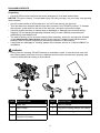 3
3
-
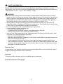 4
4
-
 5
5
-
 6
6
-
 7
7
-
 8
8
-
 9
9
-
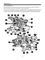 10
10
-
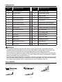 11
11
-
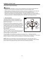 12
12
-
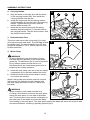 13
13
-
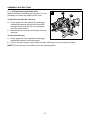 14
14
-
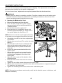 15
15
-
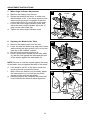 16
16
-
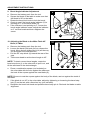 17
17
-
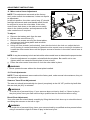 18
18
-
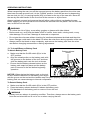 19
19
-
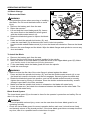 20
20
-
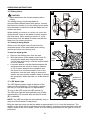 21
21
-
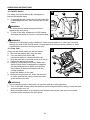 22
22
-
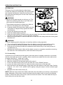 23
23
-
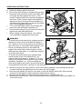 24
24
-
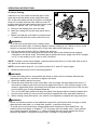 25
25
-
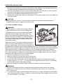 26
26
-
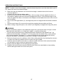 27
27
-
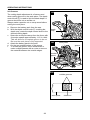 28
28
-
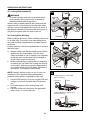 29
29
-
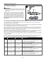 30
30
-
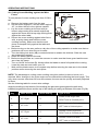 31
31
-
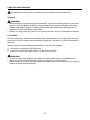 32
32
-
 33
33
-
 34
34
-
 35
35
-
 36
36
-
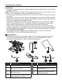 37
37
-
 38
38
-
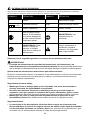 39
39
-
 40
40
-
 41
41
-
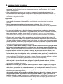 42
42
-
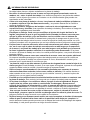 43
43
-
 44
44
-
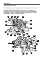 45
45
-
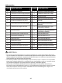 46
46
-
 47
47
-
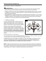 48
48
-
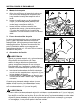 49
49
-
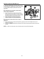 50
50
-
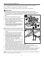 51
51
-
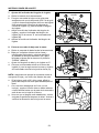 52
52
-
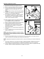 53
53
-
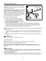 54
54
-
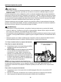 55
55
-
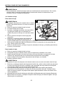 56
56
-
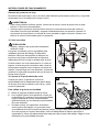 57
57
-
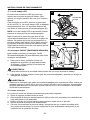 58
58
-
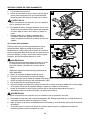 59
59
-
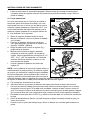 60
60
-
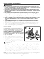 61
61
-
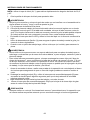 62
62
-
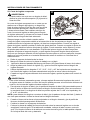 63
63
-
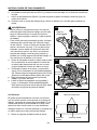 64
64
-
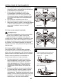 65
65
-
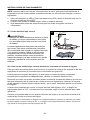 66
66
-
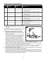 67
67
-
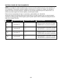 68
68
-
 69
69
-
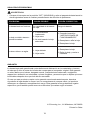 70
70
-
 71
71


Kobalt KMS 0724B-03 Guía del usuario
- Categoría
- Herramientas eléctricas
- Tipo
- Guía del usuario
en otros idiomas
- English: Kobalt KMS 0724B-03 User guide
Otros documentos
-
Ryobi P553 El manual del propietario
-
-
Ryobi P552K Manual de usuario
-
Craftsman C3 El manual del propietario
-
-
-
Ryobi TS1345L El manual del propietario
-
-
-