GYS PROMIG 400 4S El manual del propietario
- Categoría
- Sistema de soldadura
- Tipo
- El manual del propietario
Este manual también es adecuado para

FR
EN
DE
ES
RU
IT
NL
73502-V8-07/10/2019
2-9 / 58-76
PROMIG 400-4S
PROMIG 400 G DV
PROMIG 400-4S DUO DV
PROMIG 400-4S DV WS
PROMIG 400 G DV WS
10-17 / 58-76
18-25 / 58-76
26-33 / 58-76
34-41 / 58-76
50-57 / 58-76
42-49 / 58-76
www.gys.fr

2
PROMIG
FR
AVERTISSEMENTS - RÈGLES DE SÉCURITÉ
CONSIGNE GÉNÉRALE
Ces instructions doivent être lues et bien comprises avant toute opération.
Toute modication ou maintenance non indiquée dans le manuel ne doit pas être entreprise.
Tout dommage corporel ou matériel dû à une utilisation non-conforme aux instructions de ce manuel ne pourra être retenu à la charge du fabricant.
En cas de problème ou d’incertitude, consulter une personne qualiée pour manier correctement l’installation.
ENVIRONNEMENT
Ce matériel doit être utilisé uniquement pour faire des opérations de soudage dans les limites indiquées par la plaque signalétique et/ou le manuel.
Il faut respecter les directives relatives à la sécurité. En cas d’utilisation inadéquate ou dangereuse, le fabricant ne pourra être tenu responsable.
L’installation doit être utilisée dans un local sans poussière, ni acide, ni gaz inammable ou autres substances corrosives de même pour son stockage.
S’assurer d’une circulation d’air lors de l’utilisation.
Plages de température :
Utilisation entre -10 et +40°C (+14 et +104°F).
Stockage entre -20 et +55°C (-4 et 131°F).
Humidité de l’air :
Inférieur ou égal à 50% à 40°C (104°F).
Inférieur ou égal à 90% à 20°C (68°F).
Altitude :
Jusqu’à 1000 m au-dessus du niveau de la mer (3280 pieds).
PROTECTIONS INDIVIDUELLE ET DES AUTRES
Le soudage à l’arc peut être dangereux et causer des blessures graves voire mortelles.
Le soudage expose les individus à une source dangereuse de chaleur, de rayonnement lumineux de l’arc, de champs électromagnétiques (attention
au porteur de pacemaker), de risque d’électrocution, de bruit et d’émanations gazeuses.
Pour bien se protéger et protéger les autres, respecter les instructions de sécurité suivantes :
An de se protéger de brûlures et rayonnements, porter des vêtements sans revers, isolants, secs, ignifugés et en bon état, qui
couvrent l’ensemble du corps.
Utiliser des gants qui garantissent l’isolation électrique et thermique.
Utiliser une protection de soudage et/ou une cagoule de soudage d’un niveau de protection sufsant (variable selon les applica-
tions). Protéger les yeux lors des opérations de nettoyage. Les lentilles de contact sont particulièrement proscrites
Il est parfois nécessaire de délimiter les zones par des rideaux ignifugés pour protéger la zone de soudage des rayons de l’arc, des
projections et des déchets incandescents.
Informer les personnes dans la zone de soudage de ne pas xer les rayons de l’arc ni les pièces en fusion et de porter les vêtements
adéquats pour se protéger.
Utiliser un casque contre le bruit si le procédé de soudage atteint un niveau de bruit supérieur à la limite autorisée (de même pour
toute personne étant dans la zone de soudage).
Tenir à distance des parties mobiles (ventilateur) les mains, cheveux, vêtements.
Ne jamais enlever les protections carter du groupe froid lorsque la source de courant de soudage est sous tension, le fabricant ne
pourrait être tenu pour responsable en cas d’accident.
Les pièces qui viennent d’être soudées sont chaudes et peuvent provoquer des brûlures lors de leur manipulation. Lors d’interven-
tion d’entretien sur la torche ou le porte-électrode, il faut s’assurer que celui-ci soit sufsamment froid en attendant au moins 10
minutes avant toute intervention. Le groupe froid doit être allumé lors de l’utilisation d’une torche refroidie eau an d’être sûr que
le liquide ne puisse pas causer de brûlures.
Il est important de sécuriser la zone de travail avant de la quitter an de protéger les personnes et les biens.
FUMÉES DE SOUDAGE ET GAZ
Les fumées, gaz et poussières émis par le soudage sont dangereux pour la santé. Il faut prévoir une ventilation sufsante, un
apport d’air est parfois nécessaire. Un masque à air frais peut être une solution en cas d’aération insufsante.
Vérier que l’aspiration est efcace en la contrôlant par rapport aux normes de sécurité.
Attention le soudage dans des milieux de petites dimensions nécessite une surveillance à distance de sécurité. Par ailleurs le soudage de certains
matériaux contenant du plomb, cadmium, zinc ou mercure voire du béryllium peuvent être particulièrement nocifs, dégraisser également les pièces
avant de les souder.
Les bouteilles doivent être entreposées dans des locaux ouverts ou bien aérés. Elles doivent être en position verticale et maintenues à un support ou
sur un chariot.
Le soudage doit être proscrit à proximité de graisse ou de peinture.

3
PROMIG
FR
RISQUES DE FEU ET D’EXPLOSION
Protéger entièrement la zone de soudage, les matières inammables doivent être éloignées d’au moins 11 mètres.
Un équipement anti-feu doit être présent à proximité des opérations de soudage.
Attention aux projections de matières chaudes ou d’étincelles et même à travers des ssures, elles peuvent être source d’incendie ou d’explosion.
Éloigner les personnes, les objets inammables et les containers sous pressions à une distance de sécurité sufsante.
Le soudage dans des containers ou des tubes fermés est à proscrire et dans le cas où ils sont ouverts il faut les vider de toute matière inammable
ou explosive (huile, carburant, résidus de gaz …).
Les opérations de meulage ne doivent pas être dirigées vers la source de courant de soudage ou vers des matières inammables.
BOUTEILLES DE GAZ
Le gaz sortant des bouteilles peut être source de suffocation en cas de concentration dans l’espace de soudage (bien ventiler).
Le transport doit être fait en toute sécurité : bouteilles fermées et la source de courant de soudage éteinte. Elles doivent être
entreposées verticalement et maintenues par un support pour limiter le risque de chute.
Fermer la bouteille entre deux utilisations. Attention aux variations de température et aux expositions au soleil.
La bouteille ne doit pas être en contact avec une amme, un arc électrique, une torche, une pince de masse ou toutes autres
sources de chaleur ou d’incandescence.
Veiller à la tenir éloignée des circuits électriques et de soudage et donc ne jamais souder une bouteille sous pression.
Attention lors de l’ouverture du robinet de la bouteille, il faut éloigner la tête la robinetterie et s’assurer que le gaz utilisé est
approprié au procédé de soudage.
SÉCURITÉ ÉLECTRIQUE
Le réseau électrique utilisé doit impérativement avoir une mise à la terre. Utiliser la taille de fusible recommandée sur le tableau
signalétique.
Une décharge électrique peut être une source d’accident grave direct ou indirect, voire mortel.
Ne jamais toucher les parties sous tension à l’intérieur comme à l’extérieur de la source de courant sous-tension (Torches, pinces, câbles, électrodes)
car celles-ci sont branchées au circuit de soudage.
Avant d’ouvrir la source de courant de soudage, il faut la déconnecter du réseau et attendre 2 minutes. an que l’ensemble des condensateurs soit
déchargé.
Ne pas toucher en même temps la torche ou le porte-électrode et la pince de masse.
Veiller à changer les câbles, torches si ces derniers sont endommagés, par des personnes qualiées et habilitées. Dimensionner la section des câbles
en fonction de l’application. Toujours utiliser des vêtements secs et en bon état pour s’isoler du circuit de soudage. Porter des chaussures isolantes,
quel que soit le milieu de travail.
CLASSIFICATION CEM DU MATÉRIEL
Ce matériel de Classe A n’est pas prévu pour être utilisé dans un site résidentiel où le courant électrique est fourni par le réseau
public d’alimentation basse tension. Il peut y avoir des difcultés potentielles pour assurer la compatibilité électromagnétique
dans ces sites, à cause des perturbations conduites, aussi bien que rayonnées à fréquence radioélectrique.
Ce matériel est conforme à la CEI 61000-3-12, à condition que la puissance de court-circuit Ssc soit supérieure ou égale à
3.9 MVA au point d’interface entre l’alimentation de l’utilisateur et le réseau public de distribution. Il est de la responsabilité de
l’installateur ou de l’utilisateur du matériel de s’assurer, si nécessaire en consultant l’exploitant du réseau de distribution, que le
matériel est raccordé uniquement à une alimentation ayant une puissance de court-circuit Ssc supérieure ou égale à 3.9 MVA.
Ce matériel est conforme à la CEI 61000-3-11.
ÉMISSIONS ÉLECTROMAGNÉTIQUES
Le courant électrique passant à travers n’importe quel conducteur produit des champs électriques et magnétiques (EMF) loca-
lisés. Le courant de soudage produit un champ électromagnétique autour du circuit de soudage et du matériel de soudage.
Les champs électromagnétiques EMF peuvent perturber certains implants médicaux, par exemple les stimulateurs cardiaques. Des mesures de
protection doivent être prises pour les personnes portant des implants médicaux. Par exemple, restrictions d’accès pour les passants ou une évaluation
de risque individuelle pour les soudeurs.
Tous les soudeurs devraient utiliser les procédures suivantes an de minimiser l’exposition aux champs électromagnétiques provenant du circuit de
soudage:
• positionner les câbles de soudage ensemble – les xer les avec une attache, si possible;
• se positionner (torse et tête) aussi loin que possible du circuit de soudage;
• ne jamais enrouler les câbles de soudage autour du corps;
• ne pas positionner le corps entre les câbles de soudage. Tenir les deux câbles de soudage sur le même côté du corps;
• raccorder le câble de retour à la pièce mise en œuvre aussi proche que possible à la zone à souder;
• ne pas travailler à côté de la source de courant de soudage, ne pas s’assoir dessus ou ne pas s’y adosser ;
• ne pas souder lors du transport de la source de courant de soudage ou le dévidoir.

4
PROMIG
FR
Les porteurs de stimulateurs cardiaques doivent consulter un médecin avant d’utiliser ce matériel.
L’exposition aux champs électromagnétiques lors du soudage peut avoir d’autres effets sur la santé que l’on ne connaît pas
encore
DES RECOMMANDATIONS POUR ÉVALUER LA ZONE ET L’INSTALLATION DE SOUDAGE
Généralités
L’utilisateur est responsable de l’installation et de l’utilisation du matériel de soudage à l’arc suivant les instructions du fabricant. Si des perturbations
électromagnétiques sont détectées, il doit être de la responsabilité de l’utilisateur du matériel de soudage à l’arc de résoudre la situation avec
l’assistance technique du fabricant. Dans certains cas, cette action corrective peut être aussi simple qu’une mise à la terre du circuit de soudage. Dans
d’autres cas, il peut être nécessaire de construire un écran électromagnétique autour de la source de courant de soudage et de la pièce entière avec
montage de ltres d’entrée. Dans tous les cas, les perturbations électromagnétiques doivent être réduites jusqu’à ce qu’elles ne soient plus gênantes.
Évaluation de la zone de soudage
Avant d’installer un matériel de soudage à l’arc, l’utilisateur doit évaluer les problèmes électromagnétiques potentiels dans la zone environnante. Ce qui
suit doit être pris en compte:
a) la présence au-dessus, au-dessous et à côté du matériel de soudage à l’arc d’autres câbles d’alimentation, de commande, de signalisation et de
téléphone;
b) des récepteurs et transmetteurs de radio et télévision;
c) des ordinateurs et autres matériels de commande;
d) du matériel critique de sécurité, par exemple, protection de matériel industriel;
e) la santé des personnes voisines, par exemple, emploi de stimulateurs cardiaques ou d’appareils contre la surdité;
f) du matériel utilisé pour l’étalonnage ou la mesure;
g) l’immunité des autres matériels présents dans l’environnement.
L’utilisateur doit s’assurer que les autres matériels utilisés dans l’environnement sont compatibles. Cela peut exiger des mesures de protection
supplémentaires;
h) l’heure du jour où le soudage ou d’autres activités sont à exécuter.
La dimension de la zone environnante à prendre en compte dépend de la structure du bâtiment et des autres activités qui s’y déroulent. La zone
environnante peut s’étendre au-delà des limites des installations.
Évaluation de l’installation de soudage
Outre l’évaluation de la zone, l’évaluation des installations de soudage à l’arc peut servir à déterminer et résoudre les cas de perturbations. Il convient
que l’évaluation des émissions comprenne des mesures in situ comme cela est spécié à l’Article 10 de la CISPR 11:2009. Les mesures in situ peuvent
également permettre de conrmer l’efcacité des mesures d’atténuation.
RECOMMANDATION SUR LES MÉTHODES DE RÉDUCTION DES ÉMISSIONS ÉLECTROMAGNÉTIQUES
a. Réseau public d’alimentation: Il convient de raccorder le matériel de soudage à l’arc au réseau public d’alimentation selon les recommandations
du fabricant. Si des interférences se produisent, il peut être nécessaire de prendre des mesures de prévention supplémentaires telles que le ltrage du
réseau public d’alimentation. Il convient d’envisager de blinder le câble d’alimentation dans un conduit métallique ou équivalent d’un matériel de soudage
à l’arc installé à demeure. Il convient d’assurer la continuité électrique du blindage sur toute sa longueur. Il convient de raccorder le blindage à la source
de courant de soudage pour assurer un bon contact électrique entre le conduit et l’enveloppe de la source de courant de soudage.
b. Maintenance du matériel de soudage à l’arc : Il convient que le matériel de soudage à l’arc soit soumis à l’entretien de routine suivant les
recommandations du fabricant. Il convient que tous les accès, portes de service et capots soient fermés et correctement verrouillés lorsque le matériel
de soudage à l’arc est en service. Il convient que le matériel de soudage à l’arc ne soit modié en aucune façon, hormis les modications et réglages
mentionnés dans les instructions du fabricant. Il convient, en particulier, que l’éclateur d’arc des dispositifs d’amorçage et de stabilisation d’arc soit réglé
et entretenu suivant les recommandations du fabricant.
c. Câbles de soudage : Il convient que les câbles soient aussi courts que possible, placés l’un près de l’autre à proximité du sol ou sur le sol.
d. Liaison équipotentielle : Il convient d’envisager la liaison de tous les objets métalliques de la zone environnante. Toutefois, des objets métalliques
reliés à la pièce à souder accroissent le risque pour l’opérateur de chocs électriques s’il touche à la fois ces éléments métalliques et l’électrode. Il convient
d’isoler l’opérateur de tels objets métalliques.
e. Mise à la terre de la pièce à souder : Lorsque la pièce à souder n’est pas reliée à la terre pour la sécurité électrique ou en raison de ses
dimensions et de son emplacement, ce qui est le cas, par exemple, des coques de navire ou des charpentes métalliques de bâtiments, une connexion
raccordant la pièce à la terre peut, dans certains cas et non systématiquement, réduire les émissions. Il convient de veiller à éviter la mise à la terre des
pièces qui pourrait accroître les risques de blessure pour les utilisateurs ou endommager d’autres matériels électriques. Si nécessaire, il convient que le
raccordement de la pièce à souder à la terre soit fait directement, mais dans certains pays n’autorisant pas cette connexion directe, il convient que la
connexion soit faite avec un condensateur approprié choisi en fonction des réglementations nationales.
f. Protection et blindage : La protection et le blindage sélectifs d’autres câbles et matériels dans la zone environnante peuvent limiter les problèmes
de perturbation. La protection de toute la zone de soudage peut être envisagée pour des applications spéciales.
TRANSPORT ET TRANSIT DE LA SOURCE DE COURANT DE SOUDAGE
Ne pas utiliser les câbles ou torche pour déplacer la source de courant de soudage. Elle doit être déplacée en position verticale.
Ne pas faire transiter la source de courant au-dessus de personnes ou d’objets.
Ne jamais soulever une bouteille de gaz et la source de courant en même temps. Leurs normes de transport sont distinctes.
Il est préférable d’enlever la bobine de l avant tout levage ou transport de la source de courant de soudage.
Les courants de soudage vagabonds peuvent détruire les conducteurs de terre, endommager l’équipement et les dispositifs électriques
et causer des échauffements de composants pouvant entrainer un incendie.

5
PROMIG
FR
- Toutes les connexions de soudages doivent être connectées fermement, vérier régulièrement !
- S’assurer que la xation de la pièce est solide et sans problèmes électriques !
- Attacher ou suspendre tous les éléments conducteurs d’électricité de la source de soudage comme le châssis, le chariot et les systèmes de levage
pour qu’ils soient isolés !
- Ne pas déposer d’autres équipements comme des perceuses, dispositifs d’affutage, etc sur la source de soudage, le chariot, ou les systèmes de
levage sans qu’ils soient isolés !
- Toujours déposer les torches de soudage ou portes électrodes sur une surface isolée quand ils ne sont pas utilisés !
INSTALLATION DU MATÉRIEL
• Mettre la source de courant de soudage sur un sol dont l’inclinaison maximum est de 10°.
• Prévoir une zone sufsante pour aérer la source de courant de soudage et accéder aux commandes.
• Ne pas utiliser dans un environnement comportant des poussières métalliques conductrices.
• La source de courant de soudage doit être à l’abri de la pluie battante et ne pas être exposée aux rayons du soleil.
• Le matériel est de degré de protection IP21, signiant :
- une protection contre l’accès aux parties dangereuses des corps solides de diam >12.5 mm et,
- une protection contre les chutes verticales de gouttes d’eau
Les câbles d’alimentation, de rallonge et de soudage doivent être totalement déroulés an d’éviter toute surchauffe.
Le fabricant n’assume aucune responsabilité concernant les dommages provoqués à des personnes et objets dus à une utilisation
incorrecte et dangereuse de ce matériel.
ENTRETIEN / CONSEILS
• L’entretien ne doit être effectué que par une personne qualiée. Un entretien annuel est conseillé.
• Couper l’alimentation en débranchant la prise, et attendre deux minutes avant de travailler sur le matériel. A l’intérieur, les
tensions et intensités sont élevées et dangereuses.
• Régulièrement, enlever le capot et dépoussiérer à la soufette. En proter pour faire vérier la tenue des connexions électriques
avec un outil isolé par un personnel qualié.
• Contrôler régulièrement l’état du cordon d’alimentation. Si le câble d’alimentation est endommagé, il doit être remplacé par le
fabricant, son service après-vente ou une personne de qualication similaire, an d’éviter tout danger.
• Laisser les ouïes de la source de courant de soudage libres pour l’entrée et la sortie d’air.
• Ne pas utiliser cette source de courant de soudage pour dégeler des canalisations, recharger des batteries/accumulateurs ou
démarrer des moteurs.
INSTALLATION (FIG-I) – FONCTIONNEMENT PRODUIT
DESCRIPTION
Merci de votre choix ! An de tirer le maximum de satisfaction de votre poste, veuillez lire avec attention ce qui suit :
Les Promig sont des postes de soudure semi-automatique « synergic » sur roues, ventilés pour le soudage (MIG ou MAG). Ils sont
recommandés pour le soudage des aciers, des inox, des aluminiums. Leur réglage est simple et rapide grâce à leur fonction « vitesse
de l synergique ». Ils fonctionnent sur une alimentation 400V triphasée ou 230V triphasée pour les modèles DV.
Pour fonctionner le générateur PROMIG :
• 400 G DV doit être utilisé avec le dévidoir séparé TF-4RN (ref. 061699) et un faisceau de liaison.
• 400 DUO DV doit être utilisé avec le dévidoir séparé TF-4RN (ref. 061699) et un faisceau de liaison.
• 400 G DV WS doit être utilisé avec le dévidoir séparé TF-4W (ref. 061705) et un faisceau de liaison.
ALIMENTATION ÉLECTRIQUE
Ce matériel est livré avec prise 32 A de type EN 60309-1 et ne doit être utilisé que sur une installation électrique triphasée 400V (50-
60 Hz) à quatre ls avec un neutre relié à la terre.
Le courant effectif absorbé (I1eff) est indiqué sur le matériel, pour les conditions d’utilisation maximales. Vérier que l’alimentation
et ses protections (fusible et/ou disjoncteur) sont compatibles avec le courant nécessaire en utilisation. Dans certains pays, il peut
être nécessaire de changer la prise pour permettre une utilisation aux conditions maximales.
Alimentation 230V triphasée du Promig 400 G DV, 400 DUO DV, 400 DV WS et 400 G DV WS:
ATTENTION : ces appareils sont pré-montés en usine en 400V triphasée. Si votre installation
électrique est en 230V triphasée, veuillez modier le branchement de la plaque à bornes à
l’intérieur du poste. Cette manipulation doit être effectuée par une personne qualiée. Pour
ce faire se référer au schéma de branchement 230V situé à l’intérieur du poste. L’alimentation
électrique doit être protégée par un disjoncteur 25A et un différentiel 30mA.

6
PROMIG
FR
DESCRIPTION DU POSTE (FIG-II)
1- Interrupteur marche – arrêt du générateur
2- Commutateur de réglage de tension
3- Clavier de réglages des paramètres de soudage
(mode manuel ou automatique).
4- Raccord torche au standard européen.
5- Voyant de protection thermique sur le clavier de commande :
signale une coupure thermique lorsque l’appareil est utilisé de
façon intensive (coupure de plusieurs minutes).
6- Support torches avant
7- Sortie pince de masse
8- Support bouteille (maxi une bouteille de 10m3).
9- Support bobine Ø 200/300 mm.
10- Entrée gaz 1 du dévidoir intégré (400-4S et 400-4S DUO)
11- Support cables arrière.
12- Entrée gaz 2 du dévidoir séparé (400-4S DUO et 400 G)
13- Sortie gaz 2 du dévidoir séparé (400-4S DUO et 400 G)
14- Connecteur de commande du dévidoir séparé
(400-4S DUO et 400 G)
15- Connecteur de puissance du dévidoir séparé
(400-4S DUO et 400 G)
16- Interrupteur de sélection de potentiomètre de la vitesse l
(uniquement sur le 400 G DV)
PROMIG 400-4S WS et 400 G DV WS :
17- Interrupteur marche/arrêt du groupe de refroidissement
18- Porte fusible du groupe de refroidissement
19- Raccords eau du faisceau de liaison (400 G DV WS)
20- Raccords eau de la torche (400-4S WS)
SOUDAGE SEMI-AUTOMATIQUE EN ACIER/INOX (MODE MAG) (FIG-III)
Les Promig 400 peuvent souder du l acier et inox de 0,8/1 et 1,2. Ils sont livrés d’origine pour fonctionner avec du l Ø 1 mm en
acier (galet Ø 1/1,2) L’utilisation en acier ou inox nécessite un gaz spécique au soudage argon + CO2 (Ar + CO2 ). La proportion de
CO2 varie selon l’utilisation. Pour le choix du gaz, demander conseil à un distributeur de gaz. Le débit de gaz en acier se situe entre
10 et 20 L/min selon l’environnement et l’expérience du soudeur.
SOUDAGE SEMI-AUTOMATIQUE ALUMINIUM (FIG-III)
Les Promig 400 peuvent souder du l aluminium de 1 mm et 1,2 mm. (FIG-III-B) Pour souder l’aluminium, il faut utiliser un gaz
neutre: argon pur (Ar). Pour le choix du gaz, demander conseil à un distributeur de gaz. Le débit du gaz se situe entre 15 et 25 L/min
selon l’environnement et l’expérience du soudeur. Ci-dessous les différences entre l’utilisation soudage acier et soudage aluminium :
• La pression des galets presseurs du moto-dévidoir sur le l : mettre un minimum de pression an de ne pas écraser le l.
• Tube capillaire : retirer le tube capillaire avant de connecter la torche aluminium avec une gaine en téon.
• Torche : utiliser une torche spéciale aluminium. Cette torche possède une gaine téon an de réduire les frottements.
• NE PAS couper la Gaine au bord du raccord ! cette gaine sert à guider le l à partir des galets. (FIG-III-B)
• Tube contact : utiliser un tube contact SPECIAL aluminium correspondant au diamètre du l.
PROCÉDURE DE MONTAGE DES BOBINES ET DES TORCHES (FIG-IV)
Cet appareil accueille des bobines Ø 200/300 mm (écologique).
Ouvrir la trappe du poste.
• Positionner la bobine en tenant compte de l’ergot d’entrainement (3) du support bobine. Pour monter une bobine de 200mm, ins-
taller au préalable un adaptateur sur le support (ref. 042889).
• Régler le frein de la bobine (4) pour éviter lors de l’arrêt de la soudure que l’inertie de la bobine n’emmêle le l. De manière géné-
rale, ne pas serrer trop fort ! Serrer ensuite fermement la vis de maintien (2).
• Les galets moteur (8) sont des galets double gorge (Ø 0,8/ Ø 1 ou Ø 1/ Ø 1,2). L’indication qu’on lit sur le galet est celle que l’on
utilise. Pour un l de Ø 1 mm, utiliser la gorge de Ø 1. • Pour la première mise en service :
- désserrer la vis de xation du guide l (5)
- placer les galets, bien serrer leur vis de maintien (9).
- puis positionner le guide l (7) au plus près du galet mais sans contact avec ce dernier, puis resserrer la vis de xation.
• Pour régler la molette des galets presseurs (6), procéder comme suit : desserrer au maximum, actionner le moteur en appuyant
sur la gâchette de la torche, serrer la molette tout en restant appuyé sur la gâchette. Plier le l en sortie de la buse. Mettre un doigt
sur le l plié pour l’empécher d’avancer. Le réglage du serrage est bon lorsque les galets patinent sur le l même si le l est bloqué
en bout de torche.
• Réglage courant de la molette des galets (6): graduation sur 3-4 pour l’acier et graduation sur 2-3 pour l’aluminium.
CHOIX DES BOBINES
Congurations possibles:
maximum : 300 mm - 15 kg
Type l Poids (kg) Ø l (mm) Torche Gaz
Acier
Ø 300 15 0.6 / 0.8 / 1.0 / 1.2 x
Argon
+
CO2
Ø 200 5 0.6 / 0.8 / 1.0 x
Inox
Ø 200 5 0.8 x
Alu
AG5
Ø 300 7 1.0 / 1.2 x*
Argon pur
Ø 200 2 0.8 / 1.0 / 1.2 x*
*prévoir gaine téon/tube contact spécial alu. Ôter le tube capillaire
PROMIG
Ømm
0.6 > 1.6

7
PROMIG
FR
RACCORDEMENT GAZ
Visser le manodétendeur sur la bouteille de gaz si besoin est, puis connecter le tuyau fourni au raccord gaz. Pour éviter toute fuite
de gaz, utiliser les colliers fournis dans la boîte d’accessoires. Assurer le bon maintient de la bouteille de gaz en respectant la xation
de la chaine cf. FIG-IV-1. Pression maximale de gaz : 0.5 MPa (5 bars).
+
PROMIG 400-4S DUO
REFROIDISSEMENT LIQUIDE (PROMIG 400 DV WS ET 400 G DV WS)
Connecter les raccords bleu & rouge du faisceau au générateur.
Remplir le réservoir jusqu’à son niveau maximum. Le liquide de refroidissement recommandé par GYS (ref. 052246), doit impérative-
ment être utilisé. L’utilisation de liquides de refroidissement autres, et en particulier du liquide standard automobile, peut conduire,
par un phénomène d’électrolyse, à l’accumulation de dépôts solides dans le circuit de refroidissement, dégradant ainsi le refroidisse-
ment, et pouvant aller jusqu’à l’obstruction du circuit.
Toute dégradation de la machine liée à l’utilisation d’un autre liquide de refroidissement ne sera pas considérée dans le cadre de la
garantie.
Les PROMIG 400 DV WS et 400 G DV WS peuvent fonctionner avec une torche refroidie air ou une torche refroidie eau.
Pour une utilisation avec une torche refroidie air, ne pas activer l’interrupteur marche arrêt du groupe de refroidissement.
Pour une utilisation avec une torche refroidie eau, activer l’interrupteur marche arrêt du groupe de refroidissement.
Pour le PROMIG 400 DV WS et le 400 G DV WS NE JAMAIS UTILISER VOTRE POSTE SANS LIQUIDE DE REFROI-
DISSEMENT lorsque la pompe est en fonctionnement. Respecter le niveau minimal (jauge face arrière)
En cas de non respect, vous risquez de détériorer de manière dénitive la pompe du système de refroidissement.
• Respecter les règles classiques du soudage.
• Laisser les ouïes de l’appareil libres pour l’entrée et la sortie d’air.
• Laisser l’appareil branché quelques minutes après soudage pour permettre le refroidissement.
CLAVIER DE COMMANDE (FIG-V)
Choix du mode de soudage (2)
- NORMAL (2T) : soudage standard 2 temps
- NORMAL (4T) : soudage standard 4 temps
- SPOT : fonction bouchonnage /spot, Avec réglage du diamètre
du point
Réglage de la vitesse l (4) Potentiomètre d’ajustage de la
vitesse du l. La vitesse varie de 1 à 20 m/minute.
Potentiomètre de réglage SPOT (5) : Fait varier la durée du
point, la taille du point et l’intervalle entre chaque point.
Mode Manual (1)
En mode manuel, la vitesse de dévidage du l est déterminée
par l’utilisateur en ajustant le potentiomètre (4).
Mode Synergic (3)
Positionner le potentiomètre (4) au milieu de la zone «OPTIMAL
SYNERGIC »
Dans ce mode le poste détermine la vitesse de l optimale à
partir de 3 paramètres :
- Tension
- Diamètre du l
- Nature du l
Il est possible d’ajuster la vitesse du l + / - avec le potentiomètre
(4)

8
PROMIG
FR
MODE "MANUEL" (FIG-V)
Pour régler votre poste procéder comme suit :
• Choisissez la tension de soudage à l’aide des commutateurs 2*7 positions (selon le poste).
- exemple :
Pour souder de l’acier 1 mm avec un l de diamètre ø 0,8 mm mettez le commutateur sur la position A-1
• Ajustez la vitesse du l à l’aide du potentiomètre (4).
Uniquement en mode manuel, cette fonction permet de visualiser précisément le réglage de la vitesse l
sur l’afcheur.
Conseils:
L’ajustement de la vitesse du l se fait souvent « au bruit » : l’arc doit être stable et avoir très peu de crépitement. Si la vitesse
est trop faible, l’arc n’est pas continu. Si la vitesse est trop élevée, l’arc crépite et le l a tendance à repousser la torche.
MODIFICATION DES PARAMÈTRES D’USINE :
L’appareil contrôle le burn back, le post gaz et la vitesse d’accostage. Il est possible de régler les paramètres usine grâce aux menu
caché.
Entrez dans le mode caché en restant appuyé 3 s. sur la touche «MODE» (2).
Faire déler les différentes fonction avec la touche «MODE» (2).
F06 : En mode manuel, réglage du Burn back. Cette fonction permet d’éviter au l de venir se coller au tube contact en n de cordon.
La plage de réglage varie de -20ms à 70ms avec les touches TYPE (-) et WIRE (+).
F07 : En mode manuel, réglage du Post gaz. Réglage du temps pendant lequel le gaz continu de protéger le bain de fusion à la n
du cordon. La plage de réglage varie de 0ms à 950ms avec les touches TYPE (-) et WIRE (+).
F08 : En mode manuel et synergique, réglage de la vitesse d’accostage. Réglage de la vitesse de l avant la détection de courant.
La plage de réglage varie de 50 à 120 % avec les touches TYPE (-) et WIRE (+).
PARAMÉTRAGE EXPERT (SELON NORME EN 1090)
An de satisfaire aux exigences de la norme EN 1090, l’appareil réalise des DMOS (Descriptif du Mode Opératoire de Soudage) et aide
à la réalisation des QMOS
,
il est possible d’étalonner la tension, le courant et la vitesse l de l’appareil. Attention : l’étalonnage doit
se faire par GYS ou le distributeur s’il possède un service de maintenance qualié. Équipements nécessaires : Charge résistive (réf :
060418), tachymètre, voltmètre et ampèremètre
(réf : 053984).
1/ Étalonnage de la tension et du courant :
Les fonctions F00 (tension) et F01 (courant) sont réglables en menu caché. Ces fonctions sont accessible après un appui de 3s. sur
la touche MODE. La plage de réglage varie de -20% à +20% par pas de 1%.
2/ Étalonnage de la vitesse l :
ATTENTION : Pour l’afchage de la vitesse l, un étalonnage est nécessaire pour chaque conguration de soudage.
Les fonctions F02 (moteur interne) et F05 (dévidoir séparé) sont réglables en menu caché (accessible après un appui de 3s. sur
MODE). La plage de réglage varie de -20% à +20% par pas de 1%.
Pour sortir des menus cachés, faire déler les fonctions avec la touche MODE jusqu’à «END».
MODE "SYNERGIC" (FIG-V)
Grâce à cette fonction, plus besoin de régler la vitesse l.
• Positionner le potentiomètre (4) vitesse l au milieu de la zone « Optimal synergic » • Sélectionner :
- La nature du l (3)
- le diamètre du l (3)
- La puissance (commutateur en face avant)
Pour sélectionner la position adéquate en fonction de l’épaisseur à souder se référer au tableau « mode synergic » (g. VI). A partir
de cette combinaison de paramètres, cet appareil détermine la vitesse de l optimale et le poste est prêt à souder. Il est ensuite
possible d’ajuster la vitesse l si nécessaire en + ou en – grâce au potentiomètre (4). Une mémorisation des dernières congurations
de soudage est effectuée et réactivée à chaque mise en route du poste ou à chaque appui sur la gâchette d’une des torches du
générateur ou du dévidoir séparé (diamètre l, nature l, mode).
RISQUE DE BLESSURE LIÉ AUX COMPOSANTS MOBILES
Les dévidoirs sont pourvus de composants mobiles qui peuvent happer les mains, les cheveux, les vêtements ou les outils
et entraîner par conséquent des blessures !
• Ne pas porter la main aux composants pivotants ou mobiles ou encore aux pièces d’entraînement!
• Veiller à ce que les couvercles du carter ou couvercles de protection restent bien fermés pendant le fonctionnement !
Ne pas porter de gants lors de l’enlement du l d’apport et du changement de la bobine du l d’apport.

9
PROMIG
FR
CONSEIL ET PROTECTION THERMIQUE
• L’appareil ne doit pas être élingué par ses poignées, ses supports torches ou son plateau supérieur mais par le dessous du poste.
La bouteille ne doit pas être xée sur le poste durant cette opération.
• Respecter les règles classiques du soudage.
• Laisser les ouïes de l'appareil libres pour l’entrée et la sortie d’air.
• Laisser l’appareil branché après soudage pour permettre le refroidissement.
• Protection thermique : le voyant s’allume et la durée de refroidissement est de quelques minutes en fonction de la température
ambiante.

10
PROMIG
EN
WARNING - SAFETY RULES
GENERAL INSTRUCTIONS
Read and understand the following safety recommendations before using or servicing the unit.
Any change or servicing that is not specied in the instruction manual must not be undertaken.
The manufacturer is not liable for any injury or damage due to non-compliance with the instructions featured in this manual.In the event of problems
or uncertainty, please consult a qualied person to handle the inspection properly.
ENVIRONMENT
This equipment must only be used for welding operations in accordance with the limits indicated on the descriptive panel and/or in the user manual.
The operator must respect the safety precautions that apply to this type of welding. In case of inedaquate or unsafe use, the manufacturer cannot
be held liable for damage or injury.
This equipment must be used and stored in a place protected from dust, acid or any other corrosive agent. Operate the machine in an open, or well-
ventilated area.
Operating temperature:
Use between -10 and +40°C (+14 and +104°F).
Store between -20 and +55°C (-4 and 131°F).
Air humidity:
Lower or equal to 50% at 40°C (104°F).
Lower or equal to 90% at 20°C (68°F).
Altitude:
Up to 1000 meters above sea level (3280 feet).
PROTECTION OF THE INDIVIDUALS
Arc welding can be dangerous and can cause serious and even fatal injuries.
Welding exposes the user to dangerous heat, arc rays, electromagnetic elds, noise, gas fumes, and electrical shocks. People wearing pacemakers are
advised to consult with their doctor before using this device.
To protect oneself as well as the other, ensure the following safety precautions are taken:
In order to protect you from burns and radiations, wear clothing without cuffs. These clothes must be insulated, dry, reproof and
in good condition, and cover the whole body.
Wear protective gloves which guarantee electrical and thermal insulation.
Use sufcient welding protective gear for the whole body: hood, gloves, jacket, trousers... (varies depending on the application/
operation). Protect the eyes during cleaning operations. Do not operate whilst wearing contact lenses.
It may be necessary to install reproof welding curtains to protect the area against arc rays, weld spatters and sparks.
Inform the people around the working area to never look at the arc nor the molten metal, and to wear protective clothes.
Ensure ear protection is worn by the operator if the work exceeds the authorised noise limit (the same applies to any person in
the welding area).
Stay away from moving parts (e.g. engine, fan...) with hands, hair, clothes etc...
Never remove the safety covers from the cooling unit when the machine is plugged in - The manufacturer is not responsible for any
accident or injury that happens as a result of not following these safety precautions.
The pieces that have just been welded are hot and may cause burns when manipulated. During maintenance work on the torch or
the electrode holder, you should make sure it’s cold enough and wait at least 10 minutes before any intervention. The cooling unit
must be on when using a water cooled torch in order to ensure that the liquid does not cause any burns.
ALWAYS ensure the working area is left as safe and secure as possible to prevent damage or accidents.
WELDING FUMES AND GAS
The fumes, gases and dust produced during welding are hazardous. It is mandatory to ensure adequate ventilation and/or extrac-
tion to keep fumes and gases away from the work area. An air fed helmet is recommended in cases of insufcient air supply in
the workplace.
Check that the air intake is in compliance with safety standards
Care must be taken when welding in small areas, and the operator will need supervision from a safe distance. Welding certain pieces of metal
containing lead, cadmium, zinc, mercury or beryllium can be extremely toxic. The user will also need to degrease the workpiece before welding.
Gas cylinders must be stored in an open or ventilated area. The cylinders must be in a vertical position secured to a support or trolley.
Do not weld in areas where grease or paint are stored.

11
PROMIG
EN
FIRE AND EXPLOSIONS RISKS
Protect the entire welding area. Compressed gas containers and other inammable material must be moved to a minimum safe
distance of 11 meters.
A re extinguisher must be readily available.
Be careful of spatter and sparks, even through cracks. It can be the source of a re or an explosion.
Keep people, ammable objects and containers under pressure at a safe distance.
Welding of sealed containers or closed pipes should not be undertaken, and if opened, the operator must remove any inammable or explosive
materials (oil, petrol, gas...).
Grinding operations should not be directed towards the device itself, the power supply or any ammable materials.
GAS BOTTLE
Gas leaking from the cylinder can lead to suffocation if present in high concentrations around the work area.
Transport must be done safely: Cylinders closed and product off. Always keep cylinders in an upright position securely chained to
a xed support or trolley.
Close the bottle after any welding operation. Be wary of temperature changes or exposure to sunlight.
Cylinders should be located away from areas where they may be struck or subjected to physical damage.
Always keep gas bottles at a safe distance from arc welding or cutting operations, and any source of heat, sparks or ames.
Be careful when opening the valve on the gas bottle, it is necessary to remove the tip of the valve and make sure the gas meets
your welding requirements.
ELECTRIC SAFETY
The machine must be connected to an earthed electrical supply. Use the recommended fuse size.
An electrical discharge can directly or indirectly cause serious or deadly accidents .
Do not touch any live part of the machine (inside or outside) when it is plugged in (Torches, earth cable, cables, electrodes) because they are
connected to the welding circuit.
Before opening the device, it is imperative to disconnect it from the mains and wait 2 minutes, so that all the capacitors are discharged.
Do not touch the torch or electrode holder and earth clamp at the same time.
Damaged cables and torches must be changed by a qualied and skilled professional. Make sure that the cable cross section is adequate with the
usage (extensions and welding cables). Always wear dry clothes in good condition, in order to be insulated from the electrical circuit. Wear insulating
shoes, regardless of the environment in which you work in.
EMC CLASSIFICATION
These Class A devices are not intended to be used on a residential site where the electric current is supplied by the public
network, with a low voltage power supply. There may be potential difculties in ensuring electromagnetic compatibility on these
sites, because of the interferences, as well as radio frequencies.
This equipment complies with EN 61000-3-12, provided that the power of the short-circuit Ssc is equal to or greater than
3.9MVA at the interface between the machine and the mains power network. It is the responsibility of the installer or user of
the equipment to ensure if necessary by consulting the operator of the mains electricity, that the equipment is only connected
to a power supply where the power of short-circuit ssc is equal to or greater than 3.9 MVA.
This equipment complies with the CEI 61000-3-11 standard.
ELECTROMAGNETIC INTERFERENCES
The electric currents owing through a conductor cause electrical and magnetic elds (EMF). The welding current generates an
EMF eld around the welding circuit and the welding equipment.
The EMF elds may disrupt some medical implants, such as pacemakers. Protection measures should be taken for people wearing medical implants.
For example, access restrictions for passers-by or an individual risk evaluation for the welders.
All welders should take the following precautions in order to minimise exposure to the electromagnetic elds (EMF) generated by the welding circuit::
• position the welding cables together – if possible, attach them;
• keep your head and torso as far as possible from the welding circuit;
• never enroll the cables around your body;
• never position your body between the welding cables. Hold both welding cables on the same side of your body;
• connect the earth clamp as close as possible to the area being welded;
• do not work too close to, do not lean and do not sit on the welding machine
• do not weld when you’re carrying the welding machine or its wire feeder.

12
PROMIG
EN
People wearing pacemakers are advised to consult their doctor before using this device.
Exposure to electromagnetic elds while welding may have other health effects which are not yet known.
RECOMMANDATIONS TO ASSES THE AREA AND WELDING INSTALLATION
Overview
The user is responsible for installing and using the arc welding equipment in accordance with the manufacturer’s instructions. If electromagnetic
disturbances are detected, it is the responsibility of the user of the arc welding equipment to resolve the situation with the manufacturer’s technical
assistance. In some cases, this remedial action may be as simple as earthing the welding circuit. In other cases, it may be necessary to construct
an electromagnetic shield around the welding power source and around the entire piece by tting input lters. In all cases, electromagnetic
interferences must be reduced until they are no longer bothersome.
Welding area assessment
Before installing the machine, the user must evaluate the possible electromagnetic problems that may arise in the area where the installation is
planned.
. In particular, it should consider the following:
a) the presence of other power cables (power supply cables, telephone cables, command cable, etc...)above, below and on the sides of the arc
welding machine.
b) television transmitters and receivers ;
c) computers and other hardware;
d) critical safety equipment such as industrial machine protections;
e) the health and safety of the people in the area such as people with pacemakers or hearing aids;
f) calibration and measuring equipment
g)The isolation of the equipment from other machinery.
The user will have to make sure that the devices and equipments that are in the same room are compatible with each other. This may require extra
precautions;
h) make sure of the exact hour when the welding and/or other operations will take place.
The surface of the area to be considered around the device depends on the the building’s structure and other activities that take place there. The
area taken in consideration can be larger than the limits determined by the companies.
Welding area assessment
Besides the welding area, the assessment of the arc welding systems intallation itself can be used to identify and resolve cases of disturbances. The
assessment of emissions must include in situ measurements as specied in Article 10 of CISPR 11: 2009. In situ measurements can also be used to
conrm the effectiveness of mitigation measures.
RECOMMENDATION ON METHODS OF ELECTROMAGNETIC EMISSIONS REDUCTION
a. National power grid: The arc welding machine must be connected to the national power grid in accordance with the manufacturer’s
recommendation. If interferences occur, it may be necessary to take additional preventive measures such as the ltering of the power suplly
network. Consideration should be given to shielding the power supply cable in a metal conduit. It is necessary to ensure the shielding’s electrical
continuity along the cable’s entire length. The shielding should be connected to the welding current’s source to ensure good electrical contact
between the conduct and the casing of the welding current source.
b. Maintenance of the arc welding equipment: The arc welding machine should be be submitted to a routine maintenance check according to
the manufacturer’s recommendations. All accesses, service doors and covers should be closed and properly locked when the arc welding equipment
is on.. The arc welding equipment must not be modied in any way, except for the changes and settings outlined in the manufacturer’s instructions.
The spark gap of the arc start and arc stabilization devices must be adjusted and maintained according to the manufacturer’s recommendations.
c. Welding cables: Cables must be as short as possible, close to each other and close to the ground, if not on the ground.
d. Electrical bonding : consideration shoud be given to bonding all metal objects in the surrounding area. However, metal objects connected to
the workpiece increase the riskof electric shock if the operator touches both these metal elements and the electrode. It is necessary to insulate the
operator from such metal objects.
e. Earthing of the welded part : When the part is not earthed - due to electrical safety reasons or because of its size and its location (which is
the case with ship hulls or metallic building structures), the earthing of the part can, in some cases but not systematically, reduce emissions It is
preferable to avoid the earthing of parts that could increase the risk of injury to the users or damage other electrical equipment. If necessary, it is
appropriate that the earthing of the part is done directly, but in some countries that do not allow such a direct connection, it is appropriate that the
connection is made with a capacitor selected according to national regulations.
f. Protection and plating : The selective protection and plating of other cables and devices in the area can reduce perturbation issues. The
protection of the entire welding area can be considered for specic situations.
TRANSPORT AND TRANSIT OF THE WELDING MACHINE
Do not use the cables or torch to move the machine. The welding equipment must be moved in an upright position.
Do not place/carry the unit over people or objects.
Never lift the machine while there is a gas cylinder on the support shelf. A clear path is available when moving the item.
The removal of the wire reel from the machine is recommended before undertaking any lifting operation.
Stray welding currents/voltages may destroy earth conductors, damage electrical equipment or cause components to warm up which
may cause a re.

13
PROMIG
EN
- All welding connections must be rmly secured, check regularly !
- Check that the metal piece xation is strong and without any electrical problems !
- Attach or hang all the electrically conductive elements,such as the trolley in order to insulate them
- Do not place any electrical equipment such as drills on top of the welding machine without insulating them !
- Always place welding torches or electrodes holders on an insulated surface when they’re not in use !
EQUIPMENT INSTALLATION
• Put the machine on the oor (maximum incline of 10°.)
• Ensure the work area has sufcient ventillation for welding, and that there is easy access to the control panel.
• The machine must not be used in an area with conductive metal dusts.
• The machine must be placed in a sheltered area away from rain or direct sunlight.
• The machine protection level is IP21, which means :
- Protection against acess to dangerous parts from solid bodies of a ≥12.5mm diameter and,
- Protection against vertically falling drops.
The power cables, extensions and welding cables must be fully uncoiled to prevent overheating.
The manufacturer does not incur any responsability regarding damages to both objects and persons that result from an incorrect
and/or dangerous use of the machine.
MAINTENANCE / RECOMMENDATIONS
• Maintenance should only be carried out by a qualied person. Annual maintenance is recommended.
• Ensure the machine is unplugged from the mains, and wait for two minutes before carrying out maintenance work.
DANGER High Voltage and Currents inside the machine.
• Remove the casing 2 or 3 times a year to remove any excess dust. Take this opportunity to have the electrical connections
checked by a qualied person, with an insulated tool.
• Regularly check the condition of the power supply cable. If the power cable is damaged, it must be replaced by the
manufacturer, its after sales service or an equally qualied person.
• Ensure the ventilation holes of the device are not blocked to allow adequate air circulation.
• Do not use this equipment to thaw pipes, to charge batteries, or to start any engine.
INSTALLATION (FIG-I)
– PRODUCT OPERATION
DESCRIPTION
In order to get the maximum from this machine, please read the following instructions:
The Promig is a «synergic» semi-automatic welding unit, for welding (MIG or MAG). It is recommended for welding steel, stainless
steel and aluminium. Adjustment is quick and easy with the « synergic wire speed » function. It works on 3-phase 400V (or on 230V
- 3 phase for the DV models as well.)
To operate, the PROMIG :
• 400 G DV must be used with the external wire feeder TF-4RN (ref. 061699) and an interconnect cable.
• 400 DUO DV must be used with the external wire feeder TF-4RN (ref. 061699) and an interconnect cable.
• 400 G DV WS must be used with the external wire feeder TF-4W (ref. 061705) and an interconnect cable.
POWER SUPPLY
The welders are tted with a 32 A socket type EN 60309-1 which must be connected to a three-phase 400V (50 - 60 Hz) power supply
tted with four wires and one earthed neutral. The absorbed effective current (I1eff) is displayed on the machine, for optimal use.
Check that the power supply and its protection (fuse and/or circuit breaker) are compatible with the current needed by the machine.
In some countries, it may be necessary to change the plug to allow the use at maximum settings.
Power supply 3-phase 230V for the Promig 400 G DV, 400 DUO DV, 400 DV WS
et 400 G DV WS:
WARNING: these devices are pre-assembled at the factory on 3-phase 400V. If your electrical
installation is on 3-phase 230V amend the connections on the terminal block inside the product.
This operation must be done by a qualied person. Please see the electrical diagram 230V located
inside the product. The power supply must be protected by a 25A circuit breaker and a 30mA
differential.

14
PROMIG
EN
DEVICE PRESENTATION (FIG-II)
1- On - off switch of the generator
2- Voltage adjustment switch
3- Keyboard for setting welding parameters
(manual or automatic mode).
4- Torch connection according to European standard.
5- Thermal protection indicator on the control keypad: indicates
a thermal break when the device is used intensively (several
minutes shutdown).
6- Front headlamp holder
7- Ground clamp output
8- Bottle holder (max. one 10m3 bottle).
9- Coil support Ø 200/300 mm.
10- Gas inlet 1 of the integrated reel (400-4S and 400-4S DUO)
11- Rear cable support.
12- Gas inlet 2 of the separate reel (400-4S DUO and 400 G)
13- Gas outlet 2 of the separate reel (400-4S DUO and 400 G)
14- Separate reel control connector
(400-4S DUO and 400 G)
15- Separate reel power connector
(400-4S DUO and 400 G)
16- Thread speed potentiometer selection switch (only on 400
G DV)
PROMIG 400-4S WS and 400 G DV WS :
17- On/off switch for the cooling unit
18- Cooling unit fuse holder
19- Water connections of the connecting harness (400 G DV WS)
20- Water connections of the torch (400-4S WS)
SEMI-AUTOMATIC FOR STEEL/STAINLESS STEEL (MAG MODE) (FIG III)
The Promig 400 can weld 0.8/1mm and 1.2mm steel and stainless steel wires. The product is tted to work with Ø1mm steel wire
(roller Ø 1/1,2). For Steel or Stainless Steel, you will need to use a The product istted in standard to work with 0.8 steel wire. specic
gas - Argon + CO2 (Ar + CO2). The proportion of CO2 will vary depending on usage. For the specic requirements, seek advice from
your gas distributor. The gas ow in steel is between10 and 20L / min depending on the environment and experience of the welder.
SEMI-AUTOMATIC WELDING FOR ALUMINIUM
The Promig 400 can weld 1mm and 1.2mm aluminium wire. (FIG-III-B) To weld aluminium, inert gas “pure argon” (AR) is required. For
specic requirements, seek advice from your gas distributor. The gas ow in aluminium should be between 15 and 25 L / min depen-
ding on the environment and experience of the welder. Below, see the differences between steel welding and aluminium welding:
• Rollers pressure on the wire: put only the minimum pressure in order not to atten the wire.
• Capillary tube : remove the capillary tube before connecting an aluminium torch (with teon torch liner).
• Torch : using an aluminium torch. This torch has a teon torch liner to reduce friction.
• DO NOT cut the sheath near the connector ! The sheath guides the wire from the rollers. (FIG-III-B)
• Contact tip : use a SPECIAL aluminium contact tip to match the wire diameter.
REEL AND TORCH ASSEMBLY (FIG IV)
This product takes Ø 200/300 mm wire reel (ecological)
Open the door of the machine.
• Place the reel on the driving pin (3) of the reel support. To install a 200mm wire reel, t an adaptor on the support (ref. 042889).
- Adjust the reel brake (4) to avoid the reel inertia tangling the wire when welding stops. Do not overtighten! Tighten the xing screw
(2).
• The electrical rollers (8) are double groove rollers (Ø 0,8/ Ø 1 or Ø 1/ Ø 1,2). The indication on the visible side of the roller is the
diameter in use. For a Ø1 mm wire, use the Ø1 groove. • For the rst use :
- Release the xing screw which guides the wire (5)
- Fit the rollers, then tighten the screw retainer (9).
- Put the wire guide in place (7) as close as possible to the roller without contact, then tighten the xing screw.
• To set the adjusting knob of the drive rollers (6), proceed as follows: Loosen the knob fully, start the motor by pressing the torch
trigger, tighten the adjustment knob whilst pressing the trigger. Bend the wire where it comes out of the nozzle. Put a nger on the
bended wire to avoid any movement. The setting is correct when the guide roller slides over the wire even when it is blocked at the
end of the torch.
• Adjustment of the tension on the wire (6): on the scale 3-4 for steel and 2-3 for aluminium.
CHOICE OF REELS
Possible settings :
maximum : 300 mm - 15 kg
Type l Weight (kg) Ø l (mm) Torch Gas
steel
Ø 300 15 0.6 / 0.8 / 1.0 / 1.2 x
argon
+
CO2
Ø 200 5 0.6 / 0.8 / 1.0 x
stainless steel
Ø 200 5 0.8 x
Alu
AG5
Ø 300 7 1.0 / 1.2 x*
Pure argon
Ø 200 2 0.8 / 1.0 / 1.2 x*
*Make sure to have a teon torch liner/contact tip for alu. Remove the capillary tube.
PROMIG
Ømm
0.6 > 1.6

15
PROMIG
EN
GAS CONNECTION
Connect the manometer (owmeter) to the gas bottle if needed, then connect the gos hose to the gas connector. To avoid gas leak,
use collars supplied in the accessories box. Make sure the gas bottle hold in place respecting chain fastening cf. FIG-IV-1.
Maximum gas pressure : 0.5 MPa (5 bars).
+
PROMIG 400-4S DUO
LIQUID COOLING (PROMIG 400 DV WS AND 400 G DV WS)
Connect the red and blue wire of the connecting harness from the generator.
Fill the tank up to its maximum. The cooling liquid recommended by GYS (ref. 052246), must be used. The use of any other cooling liquid, and
especially the standard automobile liquid, can lead by electrolysis effect, to the accumulation of dumps in the cooling system, damaging it and even
more by blocking the circuit.
Any damage caused to the machine by the use of another cooling liquid will not be taken under warranty.
The PROMIG 400 DV WS and 400 G DV WS can be operated with an air-cooled torch or a water-cooled torch.
For use with an air-cooled torch, do not activate the on/off switch on the cooling unit.
For use with a water-cooled torch, activate the on/off switch on the cooling unit.
PROMIG 400 DV WS and 400 G DV WS : NEVER USE YOUR UNIT WITHOUT COOLING LIQUID
when the pump is working. Ensure liquid is at least minimum level (gauge at back of machine)
Failure to adhere to this may result in irreparable damage to the cooling system, and machine.
• Always respect the basic rules of welding.
• Do not block/cover the ventilation holes of the machine.
• Leave the device plugged in after welding to allow proper cooling down.
COMMAND KEYBOARD (FIG-V)
Choice of welding mode (2)
- NORMAL (2T) : standard welding 2T
- NORMAL (4T) : standard welding 4T
- SPOT : spot function, with adjustment of the spot diameter
Wire speed adjustment (4) Adjustment wire speed potentiometer.
The speed varies from 1 to 20m/minute.
SPOT adjusting potentiometer (5) : To adjust the welding time of a
point, the size of the point and the time between each point.
Manual mode (1)
In manual mode, the wire speed is determinated by the user by
adjusting the potentiometer (2).
Synergic mode (3)
Position the potentiometer (4) in the centre of the zone «OPTIMAL
SYNERGIC »
In this mode, the device determines the optimal wire speed accor-
ding to 3 parameters:
- Voltage
- Wire diameter
- Wire type
It is still possible to adjust the wire speed +/- with the potentiome-
ter (4).

16
PROMIG
EN
«MANUAL» MODE (FIG-V)
To set the machine, proceed as follows:
• Choose the welding voltage using the 2*7 positions switch (depending on the product)
Example: position A-1 to weld 1 mm steel metal sheet with ø0.8mm wire.
- Adjust the wire speed with the potentiometer(2).
In manual mode only , this function displays accurately the wire speed setting.
Advice:
The wire speed adjustment is often determinated « based on sound »: the arc must be stable and have a minimal crackling. If
the speed is too low, the arc is not continuous. If the speed is too high, the arc crackles and the wire pushes back the torch.
MODIFICATION OF FACTORY SETTINGS
The product manages the burn back and post gas. In manual mode, it is possible to adjust factory settings through the hidden menu.
Enter the hidden mode by pressing the «MODE» button (2) for 3 seconds.
Move through the different functions with the «MODE» button (2).
F06: Burn back adjustment. This function enables to avoid the wire to stick to the contact tip at the end of your weld. The adjustment
range of this product is between -10ms to 70ms with the buttons TYPE (-) and WIRE(+).
F07 : Post gaz adjustment Adjustment on how long the gas protects the welding pool at the end of the weld. The adjustment range
is between 0ms to 950ms with the buttons TYPE (-) and WIRE(+).
F08: In manual and synergic mode, Squeeze time adjustment. Adjustment of the wire speed before current detection: The adjust-
ment range is between 50 and 120£ with the buttons TYPE (-) and WIRE(+).
EXPERT SETTING (STANDARD EN 1090)
In order to comply with EN1090, the product supports WPS (Welding Procedure Specication) and helps to achieve WPQR (Welding
Procedure Qualication Record). It is possible to calibrate the voltage, the current and the wire speed of the product. Warning: the
calibration must be done by GYS or its qualied distributor. Required equipment : Dummy load (ref: 060418), tachometer, voltmeter
and ammeter (ref: 053984).
1/ Voltage and current calibration:
The functions F00 (voltage) and F01 (current) are adjustable through the hidden menu. These functions are available by pressing the
«MODE» button for 3 seconds. The setting range varies from -20% to +20%, by 1% step.
2/ Wire speed calibration:
WARNING: To display the wire speed, a calibration is required for each welding conguration.
The functions F02 (internal motor) and F05 (sparated wire feeder) are adjustable through the hidden menu (you can access it by
pressing the MODE button for 3 seconds) The setting range varies from -20% to +20%, in 1% increments.
To exit hidden menus, move through the different functions with the MODE button until you see «END».
«SYNERGIC» MODE (FIG-V)
With this function, there is no need to adjust the wire speed.
• Put the wire speed potentiometer (4) in the middle of the« Optimal synergic » zone. • Select:
-The wire type (3)
-The wire diameter (3)
-The power (switch on the front panel), to select the right position in accordance with the thickness of the part to weld, please refer
to the table «Synergic mode» (g. VI). From this combination, the device determines the optimal wire speed and the device is ready
to weld. It is also possible to adjust the wire speed if necessary by adjusting the potentiometer (4) + or – manually. A memory of
the latest welding congurations is made and is recalled each time the machine is switched on or each time a trigger of one of the
torches is pressed.
RISK OF BLESSING RELATED TO MOBILE COMPONENTS
The wire feeders contain moving parts that may catch hand, hair, clothes or tools which can lead to injuries! Take extra
care.
• Do not place your hand on mobile/pivoting/wire feeding parts of the machine!
• Make sure that all panels remain closed when in use !
Do not wear gloves when setting up the wire and changing the wire reel.

17
PROMIG
EN
ADVICE AND THERMAL PROTECTION
• The product must not be carried by its handles, torch supports or the upper panel but by the underside of the product. The gas
bottle must not be attached to the product during movement.
• Respect the basic rules of welding.
• Ensure the ventilation holes of the device are not blocked to allow adequate air circulation.
• Leave the device connected after welding to allow cooling.
• Thermal protection: The light turns on and the cooling duration is a couple of minutes inuenced by the ambient temperature

18
PROMIG
DE
SICHERHEITSANWEISUNGEN
ALLGEMEIN
Die Nichteinhaltung dieser Anweisungen und Hinweise kann mitunter zu schweren Personen- und Sachschäden führen. Neh-
men Sie keine Wartungarbeiten oder Veränderungen am Gerät vor, wenn diese nicht explizit in der Anleitung genannt werden.
Der Hersteller haftet nicht für Verletzungen oder Schäden, die durch unsachgemäße Handhabung dieses Gerätes enstanden sind. Bei Problemen oder
Fragen zum korrekten Gebrauch dieses Gerätes, wenden Sie sich bitte an entsprechend qualiziertes und geschultes Fachpersonal.
UMGEBUNG
Dieses Gerät darf ausschließlich für Schweißarbeiten für die auf dem Siebdruck-Aufdruck bzw. dieser Anleitung angegebenen Materialanforderun-
gen (Material, Materialstärke, usw) verwendet werden. Es wurde allein für die sachgemäße Anwendung in Übereinstimmung mit konventionellen
Handelspraktiken und Sicherheitsvorschriften konzipiert. Der Hersteller ist nicht für Schäden bei fehlerhaften oder gefährlichen Verwendung nicht
verantwortlich.
Verwenden Sie das Gerät nicht in Räumen, in denen sich in der Luft metallische Staubpartikel benden, die Elektrizität leiten können. Achten Sie
sowohl beim Betrieb als auch bei der Lagerung des Gerätes auf eine Umgebung, die frei von Säuren, Gasen und anderen ätzenden Substanzen ist.
Achten Sie auf eine gute Belüftung und ausreichenden Schutz bzw. Ausstattung der Räumlichkeiten.
Betriebstemperatur:
zwischen -10 und +40°C (+14 und +104°F).
Lagertemperatur zwischen -20 und +55°C (-4 und 131°F).
Luftfeuchtigkeit:
Niedriger oder gleich 50% bis 40°C (104°F).
Niedriger oder gleich 90% bis 20°C (68°F).
Das Gerät ist bis in einer Höhe von 1.000m (über NN) einsetzbar.
SICHERHEITSHINWEISE
Lichtbogenschweißen kann gefährlich sein und zu schweren - unter Umständen auch tödlichen - Verletzungen führen.
Beim Lichtbogen ist der Anwender einer Vielzahl potentieller Risiken ausgesetzt: gefährliche Hitzequelle, Lichtbogenstrahlung, elektromagnetische
Störungen (Personen mit Herzschnittmacher oder Hörgerät sollten sich vor Arbeiten in der Nähe der Maschinen von einem Arzt beraten lassen),
elektrische Schläge, Schweißlärm und -rauch.
Schützen Sie daher sich selbst und andere. Beachten Sie unbedingt die folgenden Sicherheitshinweise:
Die Strahlung des Lichtbogens kann zu schweren Augenschäden und Hautverbrennungen führen. Die Haut muss durch geeignete,
trockene Schutzbekleidung (Schweißerhandschuhe, Lederschürze, Sicherheitsschuhe) geschützt werden.
Tragen Sie bitte elektrisch- und wärmeisolierende Schutzhandschuhe.
Tragen Sie bitte Schweißschutzkleidung und einen Schweißschutzhelm mit einer ausreichenden Schutzstufe (je nach Schweißart
und -strom). Schützen Sie Ihre Augen bei Reinigungsarbeiten. Kontaktlinsen sind ausdrücklich verboten!
Schirmen Sie den Schweißbereich bei enstprechenden Umgebungsbedingungen durch Schweißvorhänge ab, um Dritte vor Licht-
bogenstrahlung, Schweißspritzern, usw. zu schützen.
In der Nähe des Lichtbogens bendliche Personen müssen ebenfalls auf Gefahren hingewiesen werden und mit den nötigen Schutz
ausgerüstet werden.
Bei Gebrauch des Schweißgerätes ensteht sehr großer Lärm, der auf Dauer das Gehör schädigt. Tragen Sie daher im Dauereinsatz
ausreichend Gehörschutz und schützen Sie in der Nähe arbeitende Personen.
Achten Sie auf einen ausreichenden Abstand mit ungeschützten Hände, Haaren und Kleidungstücken zum Lüfter.
Entfernen Sie unter keinen Umständen das Gerätegehäuse, wenn dieses am Stromnetz angeschlossen ist. Der Hersteller haftet
nicht für Verletzungen oder Schäden, die durch unsachgemäße Handhabung dieses Gerätes bzw. Nichteinhaltung der Sicherheit-
shinweise entstanden sind.
ACHTUNG! Das Werkstück ist nach dem Schweißen sehr heiß! Seien Sie daher im Umgang mit dem Werkstück vorsichtig, um
Verbrennungen zu vermeiden. Achten Sie vor Instandhaltung / Reinigung eines wassergekühlten Brenners darauf, dass Kühlag-
gregat nach Schweißende ca. 10min weiterlaufen zu lassen, damit die Kühlüssigkeit entsprechend abkühlt und Verbrennungen
vermieden werden.
Der Arbeitsbereich muss zum Schutz von Personen und Geräten vor dem Verlassen gesichert werden.
SCHWEISSRAUCH/-GAS
Beim Schweißen entstehen Rauchgase bzw. toxische Dämpfe, die zu Sauerstoffmangel in der Atemluft führen können. Sorgen Sie
daher immer für ausreichend Frischluft, technische Belüftung (oder ein zugelassenes Atmungsgerät).
Verwenden Sie die Schweßanlagen nur in gut belüfteten Hallen, im Freien oder in geschlossenen Räumen mit einer den aktuellen
Sicherheitsstandards entsprechender Absaugung.

19
PROMIG
DE
Achtung! Bei Schweißarbeiten in kleinen Räumen müssen Sicherheitsabstände besonders beachtet werden. Beim Schweißen von Blei, auch in Form
von Überzügen, verzinkten Teilen, Kadmium, «kadmierte Schrauben», Beryllium (meist als Legierungsbestandteil, z.B. Beryllium-Kupfer) und andere
Metalle entstehen giftige Dämpfe. Erhöhte Vorsicht gilt beim Schweißen von Behältern. Entleeren und reinigen Sie diese zuvor. Um die Bildung von
Giftgasen zu vermeiden bzw. zu verhindern, muss der Schweißbereich des Werkstückes von Lösungs- und Entfettungsmitteln gereinigt werden.
Die zum Schweißen benötigten Gasaschen müssen in gut belüfteter, gesicherter Umgebung aufbewahrt werden. Lagern Sie sie ausschließlich in
vertikaler Position und sichern Sie sie z.B. mithilfe eines entsprechenden Gasaschenfahrwagens gegen Umkippen. Informationen zum richtigen
Umgang mit Gasaschen erhalten Sie von Ihrem Gaselieferanten.
Schweißarbeiten in unmittelbarer Nähe von Fett und Farben sind grundsätzlich verboten!
BRAND- UND EXPLOSIONSGEFAHR
Sorgen Sie für ausreichenden Schutz des Schweißbereiches. Der Sicherheitsabstand für Gasaschen (brennbare Gase) und andere
brennbare Materialien beträgt mindestens 11 Meter.
Brandschutzausrüstung muss am Schweißbplatz vorhanden sein.
Beachten Sie die beim Schweißen entstehende heiße Schlacke, Spritzer und Funken. Sie sind eine potentielle Entstehungsquelle für Feuer oder
Explosionen.
Behalten Sie einen Sicherheitsabstand zu Personen, entammbaren Gegenständen und Druckbehältern.
Schweißen Sie keine Behälter, die brennbare Materialien enthalten (auch keine Reste davon) -> Gefahr entammbarer Gase). Bei geöffneten Behältern
müssen vorhandene Reste entammbarer oder explosiver Stoffe entfernt werden.
Arbeiten Sie bei Schleifarbeiten immer in entgegengesetzer Richtung zu diesem Gerät und entammbaren Materialen.
GASDRUCKAUSRÜSTUNG
Austretendes Gas kann in hoher Konzentration zum Erstickungstod führen. Sorgen Sie daher immer für eine gut belüftete Arbeits-
und Lagerumgebung.
Achten Sie darauf, dass die Gasaschen beim Transport verschlossen sind und das Schweißgerät ausgeschaltet ist. Lagern Sie die
Gasaschen ausschließlich in vertikaler Position und sichern Sie sie z.B. mithilfe eines entsprechenden Gasaschenfahrwagens
gegen Umkippen.
Verschließen Sie die Flaschen nach jedem Schweißvorgang. Schützen Sie sie vor direkter Sonneneinstrahlung, offenem Feuer und
starken Temperaturschwankungen (z.B. sehr tiefen Temperaturen).
Positionieren Sie die Gasaschen stets mit ausreichendem Abstand zu Schweiß- und Schleifarbeiten bzw. jeder Hitze-, Funken-
und Flammenquelle.
Halten Sie mit den Gasaschen Abstand zu Hochspannung und Schweißarbeiten. Das Schweißen einer Druckglasasche ist
untersagt.
Bei Erstöffnung des Gasventils muss der Plastikverschluss/Garantiesiegel von der Flasche entfernt werden. Verwenden Sie
ausschließlich Gas, das für die Schweißarbeit mit den von Ihnen ausgewählten Materialen geeignet ist.
ELEKTRISCHE SICHERHEIT
Das Schweißgerät darf ausschließlich an einer geerdeten Netzversorgung betrieben werden. Verwenden Sie nur die empfohlenen
Sicherungen.
Das Berühren stromführender Teile kann tödliche elektrische Schläge, schwere Verbrennungen bis zum Tod verursachen.
Berühren Sie daher UNTER KEINEN UMSTÄNDEN Teile des Geräteinneren oder das geöffnete Gehäuse, wenn das Gerät im Betrieb ist..
Trennen Sie das Gerät IMMER vom Stromnetz und warten Sie zwei weitere Minuten BEVOR Sie das Gerät öffnen, damit sich die Spannung der
Kondensatoren entladen kann.
Berühren Sie niemals gleichzeitig Brenner und Masseklemme!
Der Austausch von beschädigten Kabeln oder Brennern darf nur von qualiziertem und geschultem Fachpersonal vorgenommen werden. Tragen Sie
beim Schweißen immer trockene, unbeschädigte Kleidung. Tragen Sie unabhängig von den Umgebungsbedingungen immer isolierendes Schuhwerk.
CEM-KLASSE DES GERÄTES
Der Norm EN 60974-10 entsprechend, wird dieses Gerät als Klasse A Gerät eingestuft und ist somit für den industriellen
und/oder professionellen Gebrauch geeignet. Es ist nicht für den Einsatz in Wohngebieten bestimmt, in denen die lokale
Energieversorgung über das öffentliche Niederspannungsnetz erfolgt. In diesem Umfeld ist es auf Grund von Hochfrequenz-
Störungen und Strahlungen schwierig die elektromagnetische Verträglichkeit zu gewährleisten.
Das Gerät entspricht der Norm CEI 61000-3-12 sofern die Stärke des Kurzschlusses Ssc größer oder gleich 3,9 MVA an der
Übergaebstell zwischen der Stromversorgung des Benutzers und der öffentlichen Versorgung ist. Der Installateur und der
Anwender sind dafür verantwortlich, zu gewährleisten, dass das Gerät nur an einer Stromversorgung mit einer Kurzschlussstärke
Ssc höher oder gleich 3.9 MVA angeschlossen ist, indem sie sich bei dem Betreiber des Vertriebsnetzes informieren wenn nötig.
Das Gerät entspricht der Norm CEI 61000-3-11.
ELEKTROMAGNETISCHE FELDER UND STÖRUNGEN
Der durch Leiter ießende elektrische Strom erzeugt lokale elektrische und magnetische Felder (EMF). Beim Betrieb von Licht-
bogenschweißanlagen kann es zu elektromagnetischen Störungen kommen.

20
PROMIG
DE
Durch den Betrieb dieses Gerätes können elektromedizinische, informationstechnische und andere Geräte in ihrer Funktionsweise beeinträchtigt
werden. Personen, die Herzschrittmacher oder Hörgeräte tragen, sollten sich vor Arbeiten in der Nähe der Maschine, von einem Arzt beraten lassen.
Zum Beispiel Zugangseinschränkungen für Passanten oder individuelle Risikobewertung für Schweißer.
Alle Schweißer sollten gemäß dem folgenden Verfahren die Exposition zu elektromagnetischen Feldern aus Lichtbogenschweißgeräten minimieren :
• Elektrodenhalter und Massekabel bündeln, wenn möglich machen Sie sie mit Klebeband fest;
• Achten Sie darauf, dass ihren Oberkörper und Kopf sich so weit wie möglich von der Schweißarbeit entfernt benden;
• Achten Sie darauf, dass sich die Kabel, der Brenner oder die Masseklemme nicht um Ihren Körper wickeln;
• Stehen Sie niemals zwischen Masse- und Brennerkabel. Die Kabel sollten stets auf einer Seite liegen;
• Verbinden Sie die Massezange mit dem Werkstück möglichst nahe der Schweißzone;
• Arbeiten Sie nicht unmittelbar neben der Schweißstromquelle;
• Während des Transportes der Stromquelle oder des Drahtvorschubkoffer nicht schweißen.
Personen, die Herzschrittmacher oder Hörgeräte tragen, sollten sich vor Arbeiten in der Nähe der Maschine, von einem Arzt
beraten lassen.
Durch den Betrieb dieses Gerätes können elektromedizinische, informationstechnische und andere Geräte in Ihrer Funktions-
weise beeinträchtigt werden.
HINWEIS ZUR PRÜFUNG DES SCHWEISSPLATZES UND DER SCHWEISSANLAGE
Allgemein
Der Anwender ist für den korrekten Gebrauch des Schweißgerätes und des Zubehörs gemäß der Herstellerangaben verantwortlich. Die Beseitigung
bzw. Minimierung auftretender elektromagnetischer Störungen liegt in der Verantwortung des Anwenders, ggf. mit Hilfe des Herstellers. Die korrekte
Erdung des Schweißplatzes inklusive aller Geräte hilft in vielen Fällen. In einigen Fällen kann eine elektromagnetische Abschirmung des Schweißstroms
erforderlich sein. Eine Reduzierung der elektromagntische Störungen auf ein niedriges Niveau ist auf jeden Fall erforderlich.
Prüfung des Schweißplatzes
Das Umfeld sollte vor der Einrichtung der Lichtbogenschweißeinrichtung auf potenzielle elektromagnetische Probleme geprüfen werden. Zur Bewertung
potentieller elektromagnetischer Probleme in der Umgebung muss folgendes berücksichtigt werden:
a) Netz-, Steuer-, Signal-, und Telekommunikationsleitungen;
b) Radio- und Fernsehgeräte;
c) Computer und andere Steuereinrichtungen;
d) Sicherheitseinrichtungen, zum Beispiel, Industriematerialschutz;
e) die Gesundheit benachbarter Personen, insbesondere wenn diese Herzschrittmacher oder Hörgeräte tragen;
f) Kalibrier- und Messeinrichtungen;
g) die Störfestigkeit anderer Einrichtungen in der Umgebung.
Der Anwender muss prüfen, ob andere Werkstoffe in der Umgebung benutzt werden können. Weitere Schutzmaßnahmen können dadurch erforderlich
sein;
h) die Tageszeit, zu der die Schweißarbeiten ausgeführt werden müssen.
Die Größe der zu beachtenden Umgebung ist von der Struktur des Gebäudes und der anderen dort stattndenden Aktivitäten abhängig. Die Umgebung
kann sich auch außerhalb der Grenzen der Schweißanlagen erstrecken.
Prüfung des Schweißgerätes
Neben der Überprüfung des Schweißplatzes kann eine Überprüfung des Schweißgerätes weitere Probleme lösen. Die Prüfung sollte gemäß Art. 10 der
EN/CISPR 11:2009 durchgeführt werden. In-situ Messungen können auch die Wirksamkeit der Minderungsmaßnahmen bestätigen.
HINWEIS ÜBER DIE METHODEN ZUR REDUZIERUNG ELEKTROMAGNETISCHER FELDER
a. Öffentliche Stromversorgung: Es wird empfohlen das Lichtbogenschweißgerät gemäß der Hinweise des Herstellers an die öffentliche Versor-
gung anzuschließen. Falls Interferenzen auftreten, können weitere Maßnahmen erforderlich sein (z.B. Netzlter). Eine Abschirmung der Versorgungs-
kabel durch ein Metallrohr kann erforderlich sein. Kabeltrommeln sollten vollständig abgerollt werden. Abschirmung von anderen Einrichtungen in der
Umgebung oder der gesamten Schweißeinrichtung können erforderlich sein.
b. Wartung des Gerätes und des Zubehörs: Es wird empfohlen das Lichtbogenschweißgerät gemäß der Hinweise des Herstellers an die öffent-
liche Versorgung anzuschließen. Alle Zugänge, Betriebstüren und Deckel müssen geschlossen und korrekt verriegelt sein, wenn das Gerät in Betrieb
ist. Das Schweißgerät und das Zubehör sollten in keiner Weise geändert werden mit Ausnahme der in den Anweisungen des Geräteherstellers erwähn-
ten Änderungen und Einstellungen. Für die Einstellung und Wartung der Lichtbogenzünd- und stabilisierungseinrichtungen müssen die Anweisungen
des Geräteherstellers besonders zu beachten.
c. Schweißkabel: Schweißkabel sollten so kurz wie möglich und eng zusammen am Boden verlaufen.
d. Potenzialausgleich: Alle metallischen Teile des Schweißplatzes sollten des Schweißplatzes sollten in den Potentialausgleich einbezogen werden.
Es besteht trotzdem die Gefahr eines elektrischen Schlages, wenn Elektrode und Metallteile gleichzeitig berührt werden. Der Anwender muss sich
von metallischen Bestückungen isolieren.
e. Erdung des Werkstücks: Die Erdung des Werkstücks kann in bestimmte Fällen die Störung reduzieren. Die Erdung von Werkstücken, die Ver-
letzungsrisiken für Anwender oder Beschädigung anderer elektrischen Materialen erhöhen können, sollte vermieden werden. Die Erdung kann direkt
oder über einen Kondensator erfolgen. Der Kondensator muss gemäß der nationalen Normen gewählt werden.
f. Schutz und Trennung: Eine Abschirmung von anderen Einrichtungen in der Umgebung oder der gesamten Schweißeinrichtung kann die Störun-
gen reduzieren. Die Abschirmung der ganen Schweißzone kann für Spezialanwendungen in Betracht gezogen werden.
TRANSPORT UND TRANSIT DER SCHWEISSSTROMQUELLE
Ziehen Sie niemals an Brenner oder Kabeln, um das Gerät zu bewegen. Das Gerät darf ausschließlich in vertikaler Position transportiert
werden.
Das Gerät darf nicht über Personen oder Objekte hinweg gehoben werden.
Halten Sie sich unbedingt an die unterschiedlichen Transportrichtlinien für Schweißgeräte und Gasaschen. Diese haben verschiedene
Beförderungsnormen.
Die Drahtspule sollte vor dem Heben und Transport des Schweißgerätes entfernt werden.

21
PROMIG
DE
Schweißkriechströme können Erdungsleiter zerstören, die Schweißanlage und elektrische Geräte beschädigen und eine Erwärmung der
Bauteile verursachen, die zum Brand führen kann.
- Alle Schweißverbindungen müssen fest verbunden sein. Überprüfen Sie sie regelmäßig!
- Überprüfen Sie die Befestigung des Werkstücks! Diese muss fest und ohne elektrische Probleme sein.!
- Positionieren Sie alle elektrisch leitfähige Elemente (Rahmen, Wagen und Hebesysteme) der Schweißquelle auf, sodass sie isoliert sind !
- Legen Sie keine andere elektrisch nicht isolierten Geräte (Bohrmaschine, Schleifgeräte usw.) auf der Schweißquelle, dem Wagen oder dem
Hebesystem ab!!
- Legen Sie die Schweißbrenner oder die Elektrodenhalter auf eine isolierte Oberäsche wenn sie nicht benutzt sind
AUFSTELLUNG
• Stellen Sie das Gerät ausschließlich auf festen und sicheren Untergrund, mit einem Neigungswinkel nicht größer als 10°.
• Achten Sie auf eine gute Belüftung und ausreichend Schutz bzw. Ausstattung der Räumlichkeiten. Der Netzstecker muss zu jeder Zeit frei zugänglich
sein.
• Verwenden Sie das Gerät nicht in einer elektromagnetisch sensiblen Umgebung.
• Schützen Sie das Gerät vor Regen und direkter Sonneneinstrahlung.
• Das Gerät ist IP21 konform, d. h:
- das Gerät schützt die eingebauten Teile vor Berührungen und mittelgroße Fremdkörpern mit einem Durchmesser >12,5 mm,
- Schutzgitter gegen senkrecht fallendes Tropfwasser
Die Versorgungs-, Verlängerungs- und Schweißkabel müssen komplett abgerollt werden, um ein Überhitzungsrisiko zu verhindern.
Der Hersteller GYS haftet nicht für Verletzungen oder Schäden, die durch unsachgemäße Handhabung dieses Gerätes entstanden
sind.
WARTUNG / HINWEISE
• Alle Wartungsarbeiten müssen von qualiziertem und geschultem Fachpersonal durchgeführt werden. Eine jährliche Wartung/
Überprüfung ist empfohlen.
• Ziehen Sie den Netzstecker, bevor Sie Arbeiten an dem Gerät vornehmen. Warten Sie bis der Lüfter nicht mehr läuft. Die
Spannungen und Ströme in dem Gerät sind hoch und gefährlich.
• Nehmen Sie regelmäßig (mindenstens 2 bis 3 Mal im Jahr) das Gehäuse ab und reinigen Sie das Innere des Gerätes mit
Pressluft. Lassen Sie regelmäßig Prüfungen des GYS Gerätes auf seine elektrische Betriebssicherheit von qualiziertem Techniker
durchführen.
• Prüfen Sie regelmäßig den Zustand der Netzzuleitung. Wenn diese beschädigt ist, muss sie durch den Hersteller, seinen
Reparaturservice oder eine qualizierte Person ausgetauscht werden, um Gefahren zu vermeiden.
• Lüftungsschlitze nicht bedecken.
• Diese Stromquelle darf nicht zum Auftauen von gefrorenen Wasserleitungen, zur Batterieauadung und zum Starten von
Motoren benutzt werden.
MONTAGE (FIG-I) – FUNKTION
BESCHREIBUNG
Wir freuen uns, dass Sie sich für ein Markengerät der Firma GYS entschieden haben und danken Ihnen für das entgegengebrachte
Vertrauen. Bitte lesen Sie vor dem Erstgebrauch der Anlage sorgfältig diese Betriebsanleitung und machen Sie sie jedem Anwen-
der zugänglich, um eine einwandfreie Inbetriebnahme, Bedienung und Wartung des Gerätes zu gewährleisten. Die PROMIG sind
synergisch geregelte, fahrbare Schutzgasschweißgeräte, konzipiert um MIG/MAG- Schweißarbeiten an Stahl-, Edelstahl-, und Alumi-
niumblechen durchzuführen. Aufgrund der Funktion «synergische Drahtvorschubgeschwindigkeit» ist die Handhabung dieser Geräte
schnell und einfach. Netzanschluss: 400V dreiphasig oder 230V dreiphasig (DV Modell).
Für den Betrieb der Stromquelle PROMIG:
• 400 G DV muss mit dem Drahtvorschubkoffer TF-4RN (Art.-Nr. 061699) und mit einem Zwischenschlauchpaket ergänzt werden.
• 400 DUO DV muss mit dem Drahtvorschubkoffer TF-4RN (Art.-Nr. 061699) und mit einem Zwischenschlauchpaket ergänzt werden.
• 400 G DV WS muss mit dem Drahtvorschubkoffer TF-4W (Art.-Nr. 061705) und mit einem Zwischenschlauchpaket ergänzt werden.
NETZANSCHLUSS
Dieses Gerät wird mit einem 32 A Typ EN 60309-1 Stecker geliefert. Es muss an einer 400V (50 - 60 Hz) dreiphasigen, geerdeten
Steckdose mit vorschriftsmäßig angeschlossenem Schutzleiter betrieben werden. Der aufgenomme Strom (I1eff) bei maximaler Leis-
tung ist auf dem Gerät angegeben. Bitte prüfen Sie, ob die Stromversorgung und die Absicherung mit dem Strom, den Sie benötigen,
übereinstimmen. In Ländern mit abweichender Netzversorgungswerten kann ein Tausch des Netzsteckers erforderlich sein, um die
maximale Leistung abrufen zu können.
Netzanschluss an eine dreiphasige 230 V Steckdose + Schutzleiter bei PROMIG 400 G DV, 400
DUO DV, 400 DV WS und 400 G DV WS : ACHTUNG! Diese Geräte sind für einen dreiphasigen
400V Netzanschluss werkseitig voreingestellt. Bei Anschluss an ein dreiphasiges 230V Strom-
netz müssen die Anschlüsse entsprechend dem in Geräteinneren aufgedruckten 230V Schaltplan
geändert werden. Diese Änderungen dürfen ausschließlich von technischem Fachpersonal dur-
chgeführt werden. Absicherung: FI IΔN 30mA und Sicherungsautomat 25A Typ D.

22
PROMIG
DE
BESCHREIBUNG (S. ABB. II)
1- Ein- und Ausschalten des Generators
2- Spannungseinstellungsschalter
3- Tastatur zur Einstellung der Schweißparameter
(manueller oder automatischer Betrieb).
4- Brenneranschluss nach europäischer Norm.
5- Thermoschutzanzeige auf der Bedientastatur: Zeigt eine
thermische Unterbrechung bei intensiver Nutzung des Gerätes
an (mehrere Minuten Abschaltung).
6- Vordere Scheinwerferhalterung
7- Erdungsklemmenausgang
8- Flaschenhalter (max. eine 10m3 Flasche).
9- Spulenhalterung Ø 200/300 mm.
10- Gaseinlass 1 der integrierten Rolle
(400-4S und 400-4S DUO)
11- Hintere Kabelhalterung.
12- Gaseinlass 2 der separaten Rolle (400-4S DUO und 400 G)
13- Gasausgang 2 der separaten Trommel
(400-4S DUO und 400 G)
14- Separater Rollensteuerungsanschluss
(400-4S DUO und 400 G)
15- Separater Stromanschluss für die Spule
(400-4S DUO und 400 G)
16- Auswahlschalter für das Potentiometer der Fadengeschwin-
digkeit (nur bei 400 G DV)
PROMIG 400-4S WS und 400 G DV WS :
17- Ein-/Ausschalter für das Kühlaggregat
18- Sicherungshalter für Kühlgerät
19- Wasseranschlüsse des Anschlusskabels (400 G DV WS)
20- Wasseranschlüsse des Brenners (400-4S WS)
SYNERGISCHES STAHL-/EDELSTAHL-SCHWEISSEN (MAG MODUS) (ABB. III)
Die PROMIG 400 eignen sich zum Verschweißen von 0,8/1/1,2mm Stahl- und Edelstahldrähten. Das Gerät ist werkseitig für den
Betrieb mit Ø1,0 mm Stahldraht voreingestellt (Drahtrolle Ø 1/1,2). Stahl- und Edelstahlschweißen erfordern die Verwendung spezi-
scher Mischgase z.B. Argon + CO2 (Ar+CO2). Der Mengeanteil des CO2 variiert je nach Einsatzzweck. Empfehlung: Fragen Sie den
Gasfachhandel nach dem optimalen Gas bei außergewönlichen Anwendungen. Die Gasdurchussmenge bei Stahlschweißarbeiten
beträgt in der Regel 10 bis 20L/min, je nach Umgebungsverhältnissen und individuellen Bedürfnissen des Schweißers.
SYNERGISCHES ALUMINIUM-SCHWEISSEN (ABB. III)
Die PROMIG 400 können 1mm und 1,2mm Aluminumdrähte verschweißen (Abb. III-B). Um Aluminium zu schweißen, ist die Verwen-
dung des neutralen Gas «Rein-Argon (Ar) erforderlich. Empfehlung: Fragen Sie Gasfachhandel nach dem optimalen Gas für Ihre
jeweilige Anwendung. Die Gasdurchussmenge bei Aluminiumschweißarbeiten beträgt in der Regel 15 bis 25 L/min, je nach Umge-
bungsverhältnissen und individuellen Bedürfnissen des Schweißers. Wichtige Hinweise für Aluminiumschweißen:
• der weiche Aluminiumdraht sollte mit möglichst geringem Anpressdruck zwischen den Drahtförderrollen transportiert werden, da er
sonst deformiert und ungleichmäßig gefördert wird.
• Kapillarrohr: Bei dem Einsatz eines speziellen Aluminiumbrenners sollte das im Zentralanschluss steckende Rohr entfernt werden.
• Brenner: Verwenden Sie einen speziellen Brenner für Aluminium. Diese Brenner verfügt über eine Teonführungsseele, die die
Reibung während der Drahtförderung im Schlauchpaket reduziert. Schneiden Sie die Teonseele unter keinen Umständen direkt am
Zentralanschluss ab! Die Seele dient dazu den Draht unmittelbar von den Rollen zu übernehmen (Abb. III-B).
• Kontaktrohr: Benutzen Sie ein Kontaktrohr SPEZIELL für Alu, das dem gewählten Drahtdurchmesser entspricht.
MONTAGE VON DRAHTFÜHRUNG UND BRENNER (ABB. IV)
Dies Gerät nimmt Ø 200/300 Massivdrahtspule auf (umweltfreundlich). Öffnen Sie die seitliche Geräteverkleidung.
• Positionieren Sie die Drahtrolle auf dem Aufnahmedorn (3) des Haspelträgers. Um eine 200mm Drahtrolle zu verwenden, müssen
Sie zuerst einen Adapter (Art.-Nr. 042889) am Haspelträger anbringen.
• Justieren Sie die Drahtrollenbremse (4), um die Drahtrolle bei Schweißstopp gegen Nachdrehen zu sichern. Ziehen Sie die Dra-
htrollenbremse generell nicht zu fest! Ziehen Sie die Halterungsschraube (2) fest.
• Die Antriebsrollen (8) sind mit 2 Führungsnuten versehen (Ø 0,8 / 1 bzw. Ø 1 / 1,2). Der seitlich sichtbare Wert entspricht der
aktuellen Nutbreite. Verwenden Sie für den jeweiligen Drahtdurchmesser ausschließlich die passende Nut.
• Drahttransport-Montage: - Lockern Sie die Fixierungsschrauben (5) der Drahtführung. - Legen Sie die Drahttransportrollen mit der
passenden Nut ein und ziehen Sie die Halterungsschraube (9) fest. - Positionieren Sie die Drahtführung (7) so nah wie möglich an der
Transportrolle. Die Drahtführung darf keinen Kontakt mit der Transportrolle haben. Ziehen Sie nun die Fixierungsschrauben wieder
an.
• Um den Transportdruck (6) korrekt einzustellen, betätigen Sie bei eingelegtem Draht den Brennertaster und justieren die Andruck-
mutter so, dass der Draht konstant transportiert wird. Zu starker Andruck wirkt sich negativ aus. Legen Sie zur Kontrolle den aus dem
Kontaktrohr austretenden Draht zwischen Daumen und Zeigender und lösen Sie den Brennertaster aus. Wird der Draht bei leichtem
Fingerdruck noch konstant gefördert, ist der Antrieb korrekt eingestellt.
• Übliche Andruckeinstellung des Drahttransportes (6): 3-4 für Stahl und 2-3 für Aluminum.

23
PROMIG
DE
DRAHTROLLENAUSWAHL
Mögliche Kongurationen:
maximum : 300 mm - 15 kg
Drahtsorte Gewicht (kg) Ø Draht (mm) Brenner Gas
Stahl
Ø 300 15 0.6 / 0.8 / 1.0 / 1.2 x
Argon
+
CO2
Edelstahl 5 0.6 / 0.8 / 1.0 x
Aluminium
AG5
Ø 200 5 0.8 x
Alu
AG5
Ø 300 7 1.0 / 1.2 x*
Argon pur
Ø 200 2 0.8 / 1.0 / 1.2 x*
*zusätzlich empfohlen: Teonseele und Kontaktrohre speziell für Alu. Entfernen Sie das Kapillarrohr.
PROMIG
Ømm
0.6 > 1.6
GAS-ANSCHLUSS
Montieren Sie zuerst dern Druckminderer an der Gasasche und schließen Sie danach den Gasschlauch (1) an. Um Gasverlust zu
vermeiden, verwenden Sie die in der Zubehörbox enthaltenen Schlauchklemmen. Achten Sie stets darauf, dass sich die Gasasche in
einem senkrecht stehenden und - mit Hilfe der Sicherungskette (Abb. IV-1) - ausreichend gesichertem Zustand bendet.
Maximaler Gasdruck : 0.5MPa (5 Bar).
+
PROMIG 400-4S DUO
WASSERKÜHLUNG (PROMIG 400 DV WS UND 400 G DV WS)
Schließen Sie die blauen und roten Anschlüsse an die Stromquelle.
Füllen Sie den Tank auf bis zu dem maximalen Füllstand. Das von GYS empfohlene Kühlmittel (ref. 052246) muss verwendet werden (für mehr
Information, besuchen Sie die Webseite: http://www.aqua-concept-gmbh.eu). Die Verwendung anderer Kühlüssigkeiten, insbesondere von Stan-
dardkühlüssigkeiten, kann wegen der Elektrolyseprozesse zur Bildung von festen Substanzen innerhalb des Kühlkreislaufes führen, die der Efzienz
der Kühlung schaden und unter Umständen zum Totalausfall des Systems durch Verstopfen führen können. Jegliche Schäden an der Maschine, die
durch die Verwendung eines anderen Kühlmittels verursacht werden, fallen nicht unter die Garantie.
Das PROMIG 400 DV WS und 400 G DV WS kann sowohl mit einem luft- als auch einem üssiggekühlten Brenner ausgestattet werden.
Bei Einsatz eines luftgekühlten Brenners muss das Kühlaggregat ausgeschaltet sein.
Bei Einsatz eines üssiggekühlten Brenners müssen Sie das Kühlaggregats einschalten.

24
PROMIG
DE
(PROMIG 400 DV WS und 400 G DV WS) DIE ANLAGE DARF BEI EINGESCHALTETER PUMPE NICHT OHNE KÜHL-
MITTEL BENUTZT WERDEN! Beachten Sie die Mindestfüllmenge (Füllanzeige auf der Rückseite)
Bei Nichtbeachtung beschädigen Sie die Pumpe des Kühlsystems und die Schweißbrenner.
• Beachten Sie bitte die Grundregeln des Schweißens
• Verschließen Sie nicht die Lüftungsöffnungen des Gerätes, um eine Luftzirkulation zu ermöglichen.
• Lassen Sie das Gerät nach Beendigung der Arbeit noch eine Zeit eingeschaltet, um die Abkühlung zu ermöglichen.
BEDIENEINHEIT (ABB. V)
Auswahl Brennertastermodus (2)
- NORMAL (2T): Standard 2 - Takt Schweißen
- NORMAL (4T): Standard 4 - Takt Schweißen
- SPOT: Funktion «Heftschweißen» (Intervallschaltung zum Hef-
ten), Einstellung des Schweißpunktdurchmessers.
Einstellung der Drahtvorschubgeschwindigkeit mittels drehregler
(4) von 1 bis 20m/min.
SPOT Einstellungsdrehregler (5) : Hier wird die Schweißzeit, die
Größe des Punktes, sowie der Intervall zwischen jedem Punkt
eingestellt.
Manuell Modus (1)
Im Manuell Modus wird die Drahtvorschubgeschwindigkeit mittels
drehregler vom Anwender eingestellt werden (4).
Synergic Modus (3)
Im Synergic Modus muss die Drahtvorschubgeschwindigkeit nicht
manuell eingestellt werden: Stellen Sie das drehregler (4) in der
Mitte der «OPTIMAL SYNERGIC»
Zone ein und wählen Sie aus:
- Drahttyp
- Drahtdurchmesser
- Schweißleistung : Das Gerät stellt anhand dieser Angaben auto-
matisch die optimale, werkseitig voreingstellte Drahtvorsc
«MANUELL» MODUS (ABB. V)
Gehen Sie wie folgt vor, um Ihr Gerät at einzustellen:
• Stellen Sie die Schweißspannung je nach Gerät mit dem Schalter 2*7 Stufen entsprechend der Blechdicke ein.
- Beispiel: Um 1 mm Stahlbleche mit Ø 0,8mm Draht zu verschweißen, Schweißspannungsregler auf 1 stellen.
• Drahtvorschubgeschwindigkeit mittels Drehregler (4) anpassen.
Diese Funktion ermöglicht die geanue Anzeige der Drahtgeschwindigkeit (nur im manuellen Modus).
Tipp:
Die korrekte Drahtvorschubgeschwindigkeit ist am Abbrandgeräusch zu erkennen: Der Lichtbogen sollte stabil und ohne große Spritzerbil-
dung brennen. Wenn die Geschwindigkeit zu gering ist, brennt der Lichtbogen nicht kontinuierlich. Wenn die Geschwindigkeit zu hoch ist,
erzeugt der Lichtbogen Spritzer und drückt den Brenner weg.
ÄNDERUNG DER WERKSPARAMETER (ABB-4)
Das Gerät kontrolliert den Burn-Back und die Gas-Nachströmung. Im manuellen Modus können die Werksparameter dank dem versteckten
Modus verändert werden. Aktivieren Sie den versteckten Modus durch einen 3 Sek.-Druck auf den MODUS-Schalter (2).
Durch wiederholten Druck auf den MODUS-Schalter wählen
Sie die verschiedenen Optionen an (2).
F06: Burn-Back-Einstellung. Diese Funktion verhindert, dass der Draht mit dem Kontaktrohrhalter am Ende der Naht verschweißt. Der
Einstellbereich variiert zwischen -20ms und 70ms mit den TYPE (-) und WIRE (+) Schaltern.
F07: Gas-Nachströmung-Einstellung. Zeit, die das weiterströmt um die Naht zu schützen. Der Einstellbereich reicht 0ms bis 950ms mit den
TYPE (-) und WIRE (+) Schaltern.
F08 : Im «Manuell» und «Synergic» Modus, Einstellen der Schließgeschwindigkeit. Einstellung der Drahtvorschubgeschwindigkeit vor des
Stromfühls Der Einstellbereich variiert zwischen 50 und 120% mit den TYPE (-) und WIRE (+) Schaltern.
EXPERT EINSTELLUNG (GEMÄSS NORM EN 1090)
Um die Forderungen der Norm EN 1090 zu erfüllen, erfüllt das Gerät die Anforderungen zur Qualizierung von Schweißverfahren. Span-
nung, Strom und Drahtgeschindigkeit des Geräts können kalibriert werden. Achtung: das Kalibrieren sollte durch Gys oder den Händler (bei
entsprechender Ausstattung und Qualikation) durchgeführt werden. Benötigte Werkzeuge: Kalibriergerät (Art.-Nr.: 060418), Tachymeter,
Strommesszange / Voltmeter (Art.-Nr.: 053984).

25
PROMIG
DE
1/ Kalibrieren von Spannung und Strom: Die Funktionen F00 (Spannung) und F01 (Strom) werden im versteckten Modus eingestellt.
Diese Funktionen sind nach einem 3 Sek.-Druck auf den MODUS-Schalter erreichbar. Der Einstellbereich reicht von -20% bis +20% (in 1%
Schritten).
2/Kalibrieren der Drahtgeschwindigkeit ACHTUNG: Für die Anzeige der Drahtgeschwindigkeit muss die Kalibrierung für alle Schweißver-
fahren durchgeführt werden. Die Funktionen F02 (interner Motor) und F05 (separat Drahtvorschubkoffer) werden im versteckten Modus
eingestellt (nach einem 3 Sek.-Druck auf den MODUS-Schalter erreichbar). Der Einstellbereich reicht von -20% bis +20% (in 1% Schritten).
Um den versteckten Modus zu beenden, die Funktionen mit dem MODUS-Schalter bis «ENDE» durchblättern.
«SYNERGIC» MODUS (ABB. V)
Im Synergic Modus muss die Drahtvorschubgeschwindigkeit nicht manuell eingestellt werden: * Stellen Sie den Drehregler (4) in der Mitte
der «OPTIMAL SYNERGIC» Zone ein.
• Wählen Sie aus :
- Drahttyp (3)
- Drahtdurchmesser (3)
- Schweißleistung (Stufenschalter auf der Frontseite).
Wählen Sie die richtige Position je nach Blechstärke. Orientieren Sie sich an der Referenztabelle «Synergic Modus» auf der vorherigen Seite.
Anhand dieser Parameter stellt das Gerät automatisch die optimale Drahtvorschubgeschwindigkeit schweißbereit ein. Eine Feinregulierung
erfolgt hier im «Optimal Synergic»- Bereich des Drahtvorschubreglers (4). Für die jeweiligen Brenner wird die letzte Einstellung für Dra-
htdurchmesser, Drahttyp und Modus gespeichert.
HINWEISE
Der Drahtvorschub enthät sich bewegende Teile, die die Hände, Haare oder Kleidungsstücke erfassen können und so Verletzungen
verursachen können!
• Bewegte Teile und Antriebsteile nicht anfassen!
• Entfernen Sie unter keinen Umständen das Gerätegehäuse im laufenden Betrieb.
Tragen Sie keine Handschuhe beim Einlegen des Drahtes und beim Wechseln der Drahtrolle.
HINWEISE
• Das Gerät darf nicht an den Handgriffen, den Brennerhaltern oder am oberen Teil des Gehäuses, sondern nur von unten angehoben wer-
den. Die Gasasche sollte vor dem Schweißvorgang aufgestellt werden.
• Beachten Sie bitte die Grundregeln des Schweißens.
• Verschließen Sie nicht die Lüftungsöffnungen des Gerätes, um eine Luftzirkulation zu ermöglichen.
• Lassen Sie das Gerät nach Beendigung der Arbeit noch eine Zeit eingeschaltet, um die Abkühlung zu ermöglichen.
• Thermoschutz: Nach Aueuchten der Kontrollampe benötigt das Gerät je nach Umgebungstemparatur einige Minuten zur Abkühlung.

26
PROMIG
ES
ADVERTENCIAS - NORMAS DE SEGURIDAD
CONSIGNA GENERAL
Estas instrucciones se deben leer y comprender antes de toda operación.
Toda modicación o mantenimiento no indicado en el manual no se debe llevar a cabo.
Todo daño físico o material debido a un uso no conforme con las instrucciones de este manual no podrá atribuírsele al fabricante.
En caso de problema o de incertidumbre, consulte con una persona cualicada para manejar correctamente el aparato.
ENTORNO
Este material se debe utilizar solamente para realizar operaciones de soldadura dentro de los límites indicados en el aparato y el manual. Se deben
respetar las instrucciones relativas a la seguridad. En caso de uso inadecuado o peligroso, el fabricante no podrá considerarse responsable.
La instalación se debe hacer en un local sin polvo, ni ácido, ni gas inamable u otras sustancias corrosivas incluso donde se almacene el producto.
Hay que asegurarse de que haya una buena circulación de aire cuando se esté utilizando.
Zona de temperatura :
Uso entre -10 y +40°C (+14 y +104°F).
Almacenado entre -20 y +55°C (-4 y 131°F).
Humedad del aire :
Inferior o igual a 50% a 40°C (104°F).
Inferior o igual a 90% a 20°C (68°F).
Altitud:
Hasta 1000 m por encima del nivel del mar (3280 pies).
PROTECCIÓN INDIVIDUAL Y DE LOS OTROS
La soldadura al arco puede ser peligrosa y causar lesiones graves e incluso mortales.
La soldadura expone a los individuos a una fuente peligrosa de calor, de radiación lumínica del arco, de campos electromagnéticos (atención a los que
lleven marcapasos), de riesgo de electrocución, de ruido y de emisiones gaseosas.
Para protegerse correctamente y proteger a los demás, siga las instrucciones de seguridad siguientes:
Para protegerse de quemaduras y de radiaciones, lleve ropas sin solapas, aislantes, secos, ignífugos y en buen estado que cubran
todo el cuerpo.
Utilice guantes que aseguren el aislamiento eléctrico y térmico.
Utilice una protección de soldadura y/o una capucha de soldadura de un nivel de protección suciente (variable según aplicaciones).
Protéjase los ojos durante operaciones de limpieza. Las lentillas de contacto están particularmente prohibidas.
A veces es necesario delimitar las zonas mediante cortinas ignífugas para proteger la zona de soldadura de los rayos del arco,
proyecciones y de residuos incandescentes.
Informe a las personas en la zona de soldadura de que no miren los rayos del arco ni las piezas en fusión y que lleven ropas ade-
cuadas para protegerse.
Utilice un casco contra el ruido si el proceso de soldadura alcanza un nivel de ruido superior al límite autorizado (así como cualquier
otra persona que estuviera en la zona de soldadura).
Las manos, el cabello y la ropa deben estar a distancia de las partes móviles (ventilador).
No quite nunca el cárter del grupo de refrigeración del aparato estando bajo tensión, el fabricante no podrá ser considerado res-
ponsable en caso de accidente.
Las piezas soldadas están caliente y pueden provocar quemaduras durante su manipulación. Cuando se hace un mantenimiento de
la antorcha o portaelectrodos, se debe asegurar que esta esté lo sucientemente fría y espere al menos 10 minutos antes de toda
intervención. El grupo de refrigeración se debe encender cuando se utilice una antorcha refrigerada por líquido para que el líquido
no pueda causar quemaduras.
Es importante asegurar la zona de trabajo antes de dejarla para proteger las personas y los bienes materiales.
HUMOS DE SOLDADURA Y GAS
El humo, el gas y el polvo que se emite durante la soldadura son peligrosos para la salud. Hay que prever una ventilación su-
ciente y en ocasiones puede ser necesario un aporte de aire. Una máscara de aire puede ser una solución en caso de aireación
insuciente.
Compruebe que la aspiración es ecaz controlándola conforme a las normas de seguridad.
Atención, la soldadura en los lugares de pequeñas dimensiones requiere una vigilancia a distancia de seguridad. La soldadura de algunos materiales
que contengan plomo, cadmio, zinc, mercurio o berilio pueden ser particularmente nocivos. Desengrase las piezas antes de soldarlas.
Las botellas se deben colocar en locales abiertos o bien aireados. Se deben colocar en posición vertical y sujetadas con un soporte o sobre un carro.
La soldadura no se debe efectuar cerca de grasa o de pintura.

27
PROMIG
ES
RIESGOS DE FUEGO Y DE EXPLOSIÓN
Proteja completamente la zona de soldadura, los materiales inamables deben alejarse al menos 11 metros.
Cerca de la zona de operaciones de soldadura debe haber un anti-incendios.
Atención a las proyecciones de materiales calientes o chispas incluso a través de las suras. Pueden generar un incendio o una explosión.
Aleje las personas, objetos inamables y contenedores a presión a una distancia de seguridad suciente.
La soldadura en contenedores o tubos cerrados está prohibida y en caso de que estén abiertos se les debe vaciar de cualquier material inamable o
explosivo (aceite, carburante, residuos de gas...).
Las operaciones de pulido no se deben dirigir hacia la fuente de energía de soldadura o hacia materiales inamables.
BOTELLAS DE GAS
El gas que sale de las botella puede ser una fuente de sofocamiento en caso de concentración en el espacio de soldadura (com-
probar bien).
El transporte de este se debe hacer con toda seguridad: botellas cerradas y el aparato apagado. Se deben colocar verticalmente
y sujetadas con un soporte para limitar el riesgo de caída.
Cierre la botella entre dos usos. Atención a las variaciones de temperatura y a las exposiciones al sol.
La botella no debe entrar en contacto con una llama, un arco eléctrico, una antorcha, una pinza de masa o cualquier otra fuente
de calor o de incandescencia.
Manténgalas alejadas de los circuitos eléctricos y del circuito de soldadura y no efectúe nunca una soldadura sobre una botella
a presión.
Cuidado al abrir la válvula de una botella, hay que alejar la cabeza de la válvula y asegurarse de que el gas utilizado es el apro-
piado para el proceso de soldadura.
SEGURIDAD ELÉCTRICA
La red eléctrica utilizada de tener imperativamente una conexión a tierra. Utilice el tamaño de fusible recomendado sobre la tabla
de indicaciones.
Una descarga eléctrica puede ser una fuente de accidente grave directo o indirecto, incluso mortal.
No toque nunca las partes bajo tensión tanto en el interior como en el exterior del generador de corriente cuando este está encendido (antorchas,
pinzas, cables, electrodos) ya que están conectadas al circuito de soldadura.
Antes de abrir el aparato, es necesario desconectarlo de la red eléctrica y esperar dos minutos, para que el conjunto de los condensadores se
descarguen.
No toque al mismo tiempo la antorcha o el portaelectrodos y la pinza de masa.
Cambie los cables y antorcha si estos están dañados, acudiendo a una persona cualicada. Dimensione la sección de los cables de forma adecuada
a la aplicación. Utilizar siempre ropas secas y en buen estado para aislarse del circuito de soldadura. Lleve zapatos aislantes, sin importar el lugar
donde trabaje.
CLASIFICACIÓN CEM DEL MATERIAL
Este aparato de Clase A no está previstos para ser utilizado en un lugar residencial donde la corriente eléctrica está suministrada
por la red eléctrica pública de baja tensión. En estos lugares puede encontrar dicultades a nivel de potencia para asegurar
una compatibilidad electromagnética, debido a las interferencias propagadas por conducción y por radiación con frecuencia
radioeléctrica.
Este material se ajusta a la CEI 61000-3-12, siempre y cuando la potencia de cortocircuito Ssc sea superior o igual a 3,9 MVA
en el punto de interferencia entre la alimentación del usuario y la red pública de distribución. Es responsabilidad del instalador
o del usuario del material asegurarse, si fuera necesario consultando al distribuidor, de que el material está conectado a una
red eléctrica cuya potencia de cortocircuito Ssc sea superior o igual a 3,9 MVA.
Este material es conforme a la norma CEI 61000-3-11.
EMISIONES ELECTROMAGNÉTICAS
La corriente eléctrica causa campos electromagnéticos (EMF) localizados al pasar por cualquier conductor. La corriente de sol-
dadura produce un campo electromagnético alrededor del circuito de soldadura y del material de soldadura.
Los campos electromagnéticos EMF pueden alterar algunos implantes médicos, como los estimuladores cardíacos. Se deben tomar medidas de
protección para personas con implantes médicos. Por ejemplo, restricciones de acceso para las visitas o una evaluación de riesgo individual para los
soldadores.

28
PROMIG
ES
Todos los soldadores deberían utilizar los procedimiento siguientes para minimizar la exposición a los campos electromagnéticos que provienen del
circuito de soldadura:
• Coloque los cables de soldadura juntos - fíjelos con una brida si es posible;
• Coloque su torso y su cabeza lo más lejos posible del circuito de soldadura;
• No enrolle nunca los cables de soldadura alrededor de su cuerpo;
• No coloque su cuerpo entre los cables de soldadura. Mantenga los dos cables de soldadura sobre el mismo lado de su cuerpo;
• conecte el cable a la pieza lo más cerca posible de zona a soldar;
• no trabaje junto al generador, no se siente sobre este, ni se coloque muy cerca de este.
• no suelde cuando transporte el generador de soldadura o la devanadera.
Las personas con marcapasos deben consultar un médico antes de utilizar este aparato.
La exposición a los campos electromagnéticos durante la soldadura puede tener otros efectos sobre la salud que se desconocen
hasta ahora.
RECOMENDACIONES PARA EVALUAR LA ZONA Y LA INSTALACIÓN DE SOLDADURA
Generalidades
El usuario se responsabiliza de instalar y usar el aparato siguiendo las instrucciones del fabricante. Si se detectan alteraciones electromagnéticas, el
usuario debe resolver la situación siguiendo las recomendaciones del manual de usuario o consultando el servicio técnico del fabricante. En algunos
casos, esta acción correctiva puede ser tan simple como una conexión a tierra del circuito de soldadura. En otros casos, puede ser necesario construir
una pantalla electromagnética alrededor de la fuente de corriente de soldadura y de la pieza entera con ltros de entrada. En cualquier caso, las
perturbaciones electromagnéticas deben reducirse hasta que no sean nocivas.
Evaluación de la zona de soldadura
Antes de instalar el aparato de soldadura al arco, el usuario deberá evaluar los problemas electromagnéticos potenciales que podría haber en la zona
donde se va a instalar. Lo que se debe tener en cuenta:
a) la presencia, encima, abajo y en los laterales del material de soldadura al arco de otros cables de red eléctrica, control, de señalización y de
teléfono;
b) receptores y transmisores de radio y televisión;
c) ordenadores y otros materiales de control;
d) material crítico, por ejemplo, protección de material industrial;
e) la salud de personas cercanas, por ejemplo, que lleven estimuladores cardíacos o aparatos de audición;
f) material utilizado para el calibrado o la medición;
g) la inmunidad de los otros materiales presentes en el entorno.
El usuario deberá asegurarse de que los aparatos del local sean compatibles entre ellos. Ello puede requerir medidas de protección complementarias;
h) la hora del día en el que la soldadura u otras actividades se ejecutan.
La dimensión de la zona conjunta a tomar en cuenta depende de la estructura del edicio y de las otras actividades que se lleven a cabo en el lugar.
La zona se puede extender más allá de los límites de las instalaciones.
Evaluación de la instalación de soldadura
Además de la evaluación de la zona, la evaluación de las instalaciones de soldadura al arco puede servir para determinar y resolver los problemas
de alteraciones. Conviene que la evaluación de las emisiones incluya las medidas hechas en el lugar como especicado en el Artículo 10 de la CISPR
11:2009. Las medidas hechas en el lugar pueden permitir al mismo tiempo conrmar la ecacia de las medidas de mitigación.
RECOMENDACIONES SOBRE LOS MÉTODOS DE REDUCCIÓN DE EMISIONES ELECTROMAGNÉTICAS.
a. Red eléctrica pública: conviene conectar el equipo de soldadura a la red eléctrica pública según las recomendaciones del fabricante. Si se
produjeran interferencias, podría ser necesario tomar medidas de prevención suplementarias como el ltrado de la red pública de alimentación
eléctrica. Se recomienda apantallar el cable de red eléctrica en un conducto metálico o equivalente para material de soldadura instalado de forma
ja. Conviene asegurar la continuidad eléctrica del apantallado sobre toda la longitud. Se recomienda conectar el cable apantallado al generador de
soldadura para asegurar un buen contacto eléctrico entre el conducto y la fuente de soldadura.
b. Mantenimiento del material de soldadura al arco: conviene que el material de soldadura al arco esté sometido a un mantenimiento regular
según las recomendaciones del fabricante. Los accesos, aperturas y carcasas metálicas estén correctamente cerradas cuando se utilice el material de
soldadura al arco. El material de soldadura al arco no se debe modicar de ningún modo, salvo modicaciones y ajustes mencionados en el manual
de instrucciones del fabricante. Se recomienda, en particular, que los dispositivos de cebado y de estabilización de arco se ajusten y se les haga un
mantenimiento siguiendo las recomendaciones del fabricante.
c. Cables de soldadura: Conviene que los cables sean lo más cortos posible, colocados cerca y a proximidad del suelo sobre este.
d. Conexión equipotencial: Se recomienda comprobar los objetos metálicos de la zona de alrededor que pudieran crear un paso de corriente. En
cualquier caso, los objetos metálicos junto a la pieza que se va a soldar incrementan el riesgo del operador a sufrir descargas eléctricas si toca estos
elementos metálicos y el hilo a la vez. Conviene aislar al operador de esta clase de objetos metálicos.
e. Conexión a tierra de la pieza a soldar: Cuando la pieza a soldar no está conectada a tierra para la seguridad eléctrica o debido a su dimensiones
y lugar, como es el caso, por ejemplo de carcasas metálicas de barcos o en la carpintería metálica de edicios, una conexión a tierra de la pieza puede
reducir en algunos casos las emisiones. Conviene evitar la conexión a tierra de piezas que podrían incrementar el riesgo de heridas para los usuarios
o dañar otros materiales eléctricos. Si fuese necesario, conviene que la conexión a tierra de la pieza a soldar se haga directamente, pero en algunos
países no se autoriza este conexión directa, por lo que conviene que la conexión se haga con un condensador apropiado seleccionado en función de
la normativa nacional.
f. Protección y blindaje: La protección y el blindaje selectivo de otros cables y materiales de la zona puede limitar los problemas de alteraciones.
La protección de toda la zona de soldadura puedes ser necesaria para aplicaciones especiales.
TRANSPORTE Y TRÁNSITO DE LA FUENTE DE CORRIENTE DE SOLDADURA
No utilice los cables o la antorcha para desplazar el aparato. Se debe desplazar en posición vertical.
No transporte el generador de corriente por encima de otras personas u objetos.
No eleve una botella de gas y el generador al mismo tiempo. Sus normas de transporte son distintas.
Es preferible quitar la bobina antes de elevar o transportar el generador.

29
PROMIG
ES
Las corrientes vagabundas de soldadura pueden destruir los conductores de tierra, dañar el equipo y los dispositivos eléctricos y provocar
el calentamiento de los componentes, pudiendo causar un incendio.
- Todas las conexiones de soldadura deben conectarse con rmeza, compruebe con regularidad.
- Asegúrese de que la jación de la pieza es sólida y sin problemas eléctricos.
- Fije o deje en suspensión todos los elementos conductores de electricidad de la fuente de soldadura como el chasis, carrito y los sistemas de elevado
para que estén aislados.
- No coloque otros equipos como taladros, aparatos de alado, etc sobre la fuente de soldadura, el carrito o los sistemas de elevado sin que estén
aislados.
- Coloque siempre las antorcha de soldadura o los portaelectrodos sobre una supercie aislada cuando no estén siendo utilizados.
INSTALACIÓN DEL MATERIAL
• La fuente de corriente de soldadura se debe colocar sobre una supercie cuya inclinación máxima sea 10°.
• Coloque la máquina en una zona lo sucientemente amplia para airearla y acceder a los comandos.
• No utilice en un entorno con polvos metálicos conductores.
• La máquina debe ser protegida de la lluvia y no se debe exponer a los rayos del sol.
• El material tiene un grado de protección IP21, lo cual signica:
- una protección contra el acceso a las partes peligrosas con objetos sólidos con un diámetro superior a 12.5mm.
- una protección contra gotas de agua verticales.
Los cables de alimentación, de prolongación y de soldadura deben estar completamente desenrollados para evitar cualquier sobrecalentamiento.
El fabricante no asume ninguna responsabilidad respecto a daños provocados a personas y objetos debido a un uso incorrecto y
peligroso de este aparato.
MANTENIMIENTO / CONSEJOS
• El mantenimiento sólo debe realizarlo un personal cualicado. Se aconseja efectuar un mantenimiento anual.
• Corte el suministro eléctrico, luego desconecte el enchufe y espere 2 minutos antes de trabajar sobre el aparato. En su
interior, la tensión y la intensidad son elevadas y peligrosas.
• De forma regular, quite el capó y desempolve con un soplador de aire. Aproveche la ocasión para pedir a un personal
cualicado que compruebe que las conexiones eléctricas estén bien en sitio con una herramienta aislada.
• Compruebe regularmente el estado del cable de alimentación. Si el cable de alimentación está dañado, debe ser sustituido
por el fabricante, su servicio post-venta o una persona con cualicación similar, para evitar cualquier peligro.
• Deje los oricios del equipo libres para la entrada y la salida de aire.
INSTALACIÓN (FIG-I) - FUNCIONAMIENTO DEL PRODUCTO
DESCRIPCIÓN
¡Gracias por su elección! Para sacar el mayor provecho de su equipo, lea atentamente lo siguiente:
Los PROMIG son equipos de soldadura semiautomáticos « sinérgicos » sobre ruedas y ventilados, para la soldadura MIG/MAG. Reco-
mendados para la soldadura de acero, acero inoxidable y aluminio. Su conguración es simple y rápida mediante su modo « velocidad
de hilo sinérgica ». Funcionan bajo una red eléctrica de 400V trifásica o 230V trifásica en los modelos DV.
Para funcionar, el generador PROMIG :
• 400 G DV debe utilizarse con la devanadera separada TF-4R (ref. 061699) y un cable de unión.
• 400 DUO DV debe utilizarse con la devanadera separada TF-4R (ref. 061699) y un cable de unión.
• 400 G DV WS debe utilizarse con la devanadera separada TF-4W (ref. 061705) y un cable de unión.
ALIMENTACIÓN ELÉCTRICA
Este material incluye una clavija de 32 A de tipo EN 60309-1 y se debe conectar a una instalación eléctrica trifásica de 400V (50-60
Hz) de cuatro hilos con el neutro conectado a tierra.
La corriente efectiva absorbida (I1eff) está señalada sobre el equipo para condiciones de uso máximas. Compruebe que el suministro
eléctrico y sus protecciones (fusible y/o disyuntor) sean compatibles con la corriente necesaria durante su uso. En ciertos países
puede ser necesario cambiar la toma de corriente para condiciones de uso máximas.
Alimentación eléctrica de 230V trifásica con el Promig 400 G DV, 400 DUO DV, 400
DV WS y 400 G DV WS :
ATENCIÓN : estos aparatos están pre-montados en fábrica en 400V trifásica. Si su instalación
eléctrica es de 230V trifásica, modique la conexión de la placa de terminales en el interior del
equipo. Esta manipulación sólo debe realizarla un personal cualicado. Para hacer esto reérase
al esquema de conexión de 230V situado en el interior del equipo. La alimentación eléctrica debe
estar protegido por un disyuntor de 25A y un diferencial de 30mA.

30
PROMIG
ES
DESCRIPCIÓN DEL EQUIPO (FIG-II)
1- Interruptor de encendido y apagado del generador
2- Interruptor de ajuste de tensión
3- Teclado para el ajuste de los parámetros de soldadura
(modo manual o automático).
4- Conexión de antorcha según norma europea.
5- Indicador de protección térmica en el panel de control: indica
una rotura de puente térmico cuando el dispositivo se utiliza de
forma intensiva (parada de varios minutos).
6- Soporte del faro delantero
7- Salida de la pinza de tierra
8- Portabotellas (máx. una botella de 10 m3).
9- Soporte de bobina Ø 200/300 mm.
10- Entrada de gas 1 del carrete integrado
(400-4S y 400-4S DUO)
11- Soporte de cable trasero.
12- Entrada de gas 2 de la bobina separada
(400-4S DUO y 400 G)
13- Salida de gas 2 del carrete separado
(400-4S DUO y 400 G)
14- Conector de control de bobina separado
(400-4S DUO y 400 G)
15- Conector de alimentación de bobina separado
(400-4S DUO y 400 G)
16- Interruptor de selección del potenciómetro de velocidad de
rosca (sólo en 400 G DV)
PROMIG 400-4S WS y 400 G DV WS :
17- Interruptor de encendido/apagado de la unidad de refrige-
ración
18- Portafusibles de la unidad de refrigeración
19- Conexiones de agua del arnés de conexión (400 G DV WS)
20- Conexiones de agua de la linterna (400-4S WS)
SOLDADURA SEMI-AUTOMÁTICA DE ACERO/ACERO INOXIDABLE (MODO MAG) (FIG III)
Los Promig 400 pueden soldar hilo de acero y de acero inoxidable de 0,8/1 y 1,2. Los modelos 400-4S y 400-4S DUO DV incluyen de
fábrica los rodillos para funcionar con hilo de acero de Ø 1 mm (rodillo Ø 1/1,2) .La utilización con acero o acero inoxidable requiere
un gas especíco para la soldadura de argón y dióxido de carbono (Ar+CO2). La proporción de CO2 varía según el uso. Para la elec-
ción del gas, pida consejo a un distribuidor. El caudal de gas para el acero está entre 10 y 20 L/min según el entorno y la experiencia
del soldador.
SOLDADURA SEMI-AUTOMÁTICA DE ALUMINIO (FIG-III)
Los Promig 400 pueden soldar hilo de aluminio de 1mm y 1,2 mm. (FIG-III-B) Para soldar aluminio, se debe usar un gas neutro:
argón puro (Ar). Para la elección del gas, pida consejo a un distribuidor. El caudal de gas está entre 15 a 25 L/min según el entorno
y la experiencia del soldador. Aquí abajo encontrará las diferencias entre el uso de la soldadura de acero y la soldadura de aluminio:
• La presión de los rodillos prensadores de la devanadera sobre el hilo: coloque una presión mínima para no aplastar el hilo.
• Tubo capilar: quite el tubo capilar antes de conectar la antorcha para aluminio con una funda de teón. para la soldadura con
aluminio.
• Antorcha: utilice una antorcha especial aluminio. Esta antorcha tiene una funda de teón para reducir las fricciones.
• ¡NUNCA corte la funda a ras del empalme! esta funda sirve para guiar el hilo desde los rodillos. (FIG-III-B)
• Tubo contacto: utilice un tubo de contacto ESPECIAL aluminio adaptado al diámetro de hilo.
PROCEDIMIENTO DE MONTAJE DE LOS RODILLOS Y ANTORCHAS (FIG. IV)
Soportan bobinas de Ø 200/300 mm (también ecológicas).
Abra la trampilla del equipo.
• Coloque la bobina teniendo en cuenta la lengüeta de arrastre (3) del soporte de la bobina. Para instalar una bobina de 200mm,
instale anteriormente un adaptador sobre el soporte (ref. 042889).
• Ajuste el freno de la bobina (4) para evitar que la inercia de esta enrede el hilo cuando se pare la soldadura. Evite apretar dema-
siado. Apriete con rmeza el tornillo de soporte (2).
• Los rodillos (8) son rodillos de doble ranura (Ø0,8/ Ø 1 o Ø1/ Ø1,2). La indicación que se lee sobre el rodillo es la que se utiliza.
Para un hilo de Ø 1 mm, utilice la ranura de Ø 1. • Para una primera puesta en marcha :
- Aoje el tornillo de jación de la guía hilo (5)
- Coloque los rodillos, apriete el tornillo de jación. (9)
Coloque la guía del hilo (7) lo más cerca posible del rodillo pero sin tocarlo, luego apriete el tornillo de jación.
• Para ajustar la ruedecilla de los rodillos prensadores (6), proceda así: aoje al máximo, accione el motor
apretando el gatillo de la antorcha, apriete la ruedecilla mientras presiona el gatillo. Doble el hilo al salir de la boquilla. Ponga un dedo
sobre el hilo doblado para impedir que avance. El ajuste del apriete es bueno cuando los rodillos resbalan en el hilo, aunque el hilo
siga bloqueado en el extremo de la antorcha.
• El ajuste comúnmente utilizado en la ruedecilla de rodillos (6): con una graduación de 3-4 para el acero y de 2-3 para el aluminio.

31
PROMIG
ES
ELECCIÓN DE BOBINAS
Conguraciones posibles:
máximo : 300 mm - 15 kg
Tipo de hilo Peso (Kg)
ø hilo
(mm)
Antorcha Gas
acero
Ø 300 15 0.6 / 0.8 / 1.0 / 1.2 x
Argón
+
CO2
Ø 200 5 0.6 / 0.8 / 1.0 x
acero inoxidable
Ø 200 5 0.8 x
Aluminio
AG5
Ø 300 7 1.0 / 1.2 x*
Argón puro
Ø 200 2 0.8 / 1.0 / 1.2 x*
*se requiere funda de teón y tubo de contacto especial aluminio. Retire el tubo capilar
PROMIG
Ømm
0.6 > 1.6
CONEXIÓN DE GAS
Atornille el manómetro a la botella de gas si fuese necesario y conecte el conducto incluido al conector de gas. Para evitar toda fuga
de gas, utilice las abrazadera de la caja de accesorios. Asegúrese que la botella se mantiene bien mediante la jación de la cadena
(ver FIG-IV-1)
Presión máxima de gas: 0.5 MPa (5 bars).
+
PROMIG 400-4S DUO
REFRIGERACIÓN LÍQUIDA (PROMIG 400 DV WS Y 400 G DV WS) (FIG-3) Y PROTECCIÓN TÉRMICA
Conecte los conectores azul y rojo del cable de unión al generador.
Llene el depósito hasta su nivel máximo. El líquido de refrigeración recomendado por GYS (ref. 052246), se debe utilizar imperativamente (más
información en la página web : http://www.aqua-concept-gmbh.eu). El uso de otros líquido de refrigeración, y en particular de líquido estándar para
automóbiles, puede provocar, mediante un fenómeno de electrolisis, la acumulación de depósitos sólidos en el circuito de refrigeración, que dismi-
nuyen la calidad de la refrigeración y pueden llegar a obstruir el circuito.
Toda degradación de la máquina vinculada al uso de otro liquido de refrigeración no se considerará en garantía.
Las PROMIG 400 DV WS y 400 G DV WS pueden funcionar con una linterna refrigerada por aire o por agua.
Para su uso con una linterna refrigerada por aire, no active el interruptor de encendido/apagado de la unidad de refrigeración.
Para su uso con una linterna refrigerada por agua, active el interruptor de encendido/apagado de la unidad de refrigeración.

32
PROMIG
ES
Con el PROMIG 400 DV WS y 400 G DV WS no utilice nunca su equipo sin el líquido de refrigeración cuando la
bomba esté en uso. Respete el nivel mínimo (nivel frontal)
En caso de no hacerlo, se arriesga a que la bomba de sistema de refrigeración se deteriore de forma denitiva.
• Respete las reglas clásicas de la soldadura.
• Deje los oricios del equipo libres para la entrada y la salida de aire.
• Deje el aparato conectado algunos minutos después de soldar para permitir que se enfríe.
TECLADO (FIG V)
Selección del modo soldadura (2).
- NORMAL (2T) : soldadura estándar a 2 tiempos.
- NORMAL (4T) : soldadura estándar a 4 tiempos.
- SPOT : función « taponado », soldadura discontinua con ajuste
del diámetro del punto.
Ajuste de la velocidad del hilo (4) Potenciómetro de ajuste de la
velocidad del hilo. La velocidad varía de 1 a 20 m/minuto.
Potenciómetro de ajuste SPOT (5) : Hace varias la duración del
punto, el tamaño del punto y el intervalo entre cada punto.
Modo Manual (1)
En modo manual, la velocidad de devanado del hilo la determina el
soldador, ajustando el potenciómetro (4).
Modo Synergic (3)
Colocar el potenciómetro (4) en medio de la zona «OPTIMAL
SYNERGIC »
En este modo, el equipo determina la velocidad de hilo óptima a
partir de 3 parámetros :
• Tensión
• Diámetro del hilo
• Naturaleza del hilo
Es posible ajustar la velocidad del hilo + / - con el potenciómetro
(4).
MODO «MANUAL» (FIG. V)
Para ajustar su equipo, proceda como sigue :
• Elegir la tensión de soldadura con el conmutador de 2*7 posiciones (según el modelo).
- ejemplo:
Para soldar acero de 1mm con un hilo de diámetro ø 0,8 mm, ponga el conmutador en la posición A-1
- Ajuste la velocidad de hilo con el potenciómetro (4).
Solo en modo manual, esta función permite visualizar con precisión el ajuste de la velocidad de hilo en el
indicador.
Consejos:
El ajuste de la velocidad de hilo se hace a menudo por el «ruido»: el arco debe ser estable y no crepitar demasiado. Si la veloci-
dad es demasiado débil, el arco no es continuo. Si la velocidad es demasiado alta, el arco crepita y el hilo empuja la antorcha.
MODIFICACIÓN DE LOS PARÁMETROS DE FÁBRICA :
El aparato controla el burn back y el post gas. En modo manual, se puede congurar los parámetros de fábrica con el menú oculto.
Entre en este modo oculto apoyando durante 3 segundo el botón «MODE» (2).
Deplácese por las diferentes funciones con el botón «MODE» (2).
F06 : Ajuste del Burn back. Esta función permite evitar que el hilo se pegue en el tubo de contacto al nal del cordón. La zona de
ajuste varía de -20ms a 70ms con los botones TYPE (-) y WIRE (+).
F07 : Ajuste del Post gaz. Ajuste del tiempo durante el cual el gas continúa protegiendo el baño de fusión al nal de cordón. La zona
de ajuste varía de 0ms a 950ms con los botones TYPE (-) y WIRE (+).
F08: En modo manual y sinérgico, ajuste de la velocidad de acercamiento. Ajuste de la velocidad de hilo antes de la detección de
corriente. La zona de ajuste varía de 50 a 120% con los botones TYPE (-) y WIRE (+).
CONFIGURACIÓN DE EXPERTO (SEGÚN NORMA EN 1090)
Para satisfacer las exigencias de la norma EN 1090, el aparato realiza DMOS (Descripción del Modo Operativo de Soldadura) y ayuda
a la realización de QMOS, ya que se puede calibrar la tensión, la corriente y la velocidad de hilo del aparato. Atención: el calibrado
debe hacerlo GYS o su distribuidor si este posee un servicio de mantenimiento cualicado. Equipos necesarios: Carga estática de
calibración (ref: 060418), Taquímetro, voltímetro y amperímetro (ref: 053984).

33
PROMIG
ES
1/ Calibrado de la tensión de corriente :
Las funciones F00 (tensión) y F01 (corriente) se pueden ajustar en menú oculto. Estas funciones son accesibles tras apoyar durante
3 segundos el botón MODE. La zona de ajuste varía de -20% a +20% por pasos de 1%.
2/ Calibrado de la velocidad del hilo :
ATENCIÓN : Para la indicación de la velocidad del hilo, se necesita un calibrado para cada conguración de soldadura.
Las funciones F02 (motor interno) y F05 (devanadera separada) son ajustable en menú oculto (accesible tras apoyar el botón MODE
durante 3 segundos). La zona de ajuste varía de -20% a +20% por pasos de 1%.
Para salir de los menús ocultos, desplácese por las funciones con la tecla MODE hasta llegar a END.
MODO «SYNERGIC» (SINÉRGICO) (FIG. V)
Con esta función, ya no se necesita ajustar la velocidad del hilo.
• Colocar el potenciómetro (4) velocidad de hilo en medio de la zona « Optimal synergic »
• Seleccionar :
- La naturaleza del hilo (3)
- El diámetro del hilo (3)
- La potencia (conmutador en la parte delantera)
Para elegir la posición adecuada según el grosor de la pieza, compruebe la tabla « modo synergic » (g. VI). A partir de esta combi-
nación de parámetros, el equipo determina la velocidad de hilo óptima y está listo para soldar. Tras ello, se puede ajustar la velocidad
del hilo si fuese necesario con el potenciómetro (4). La última conguración de soldadura queda registrada y se reactivará cada vez
que se encienda el equipo o cuando se presiona el gatillo de una de las antorchas del generador o de la devanadera separada (diá-
metro del hilo, tipo de hilo y modo).
RIESGO DE HERIDA DEBIDO A COMPONENTES MÓVILES.
Las devanaderas contienen componentes móviles que pueden atrapar las manos, el cabello, la ropa o las herramientas y
provocar heridas.
• No coloque su mano sobre componentes giratorios o móviles, o piezas de arrastre.
• Asegúrese de que la carcasa del aparato o cubiertas de protección estén cerradas durante el funcionamiento.
No lleve guantes cuando coloque el hilo de soldadura en la motodevanadera y cuando cambie la bobina de hilo.
CONSEJOS Y PROTECCIÓN TÉRMICA
• No se puede mantener elevado el aparato por los mangos, por los suportes de antorcha o la plataforma superior. Solo por la parte
inferior del equipo. La botella no debe estar ja sobre el equipo durante esta operación.
• Respete las reglas clásicas de la soldadura.
• Deje los oricios del equipo libres para la entrada y la salida de aire.
• Deje el aparato conectado después de soldar para permitir que se enfríe.
• Protección térmica: el indicador se enciende y la duración del enfriamiento es de varios minutos en función de la temperatura
ambiente.

34
PROMIG
RU
ПРЕДОСТЕРЕЖЕНИЯ - ПРАВИЛА БЕЗОПАСНОСТИ
ОБЩИЕ УКАЗАНИЯ
Эти указания должны быть прочтены и поняты до начала сварочных работ.
Изменения и ремонт, не указанные в этой инструкции, не должны быть предприняты.
Производитель не несет ответственности за травмы и материальные повреждения связанные с несоответствующим данной инструкции
использованием аппарата.
В случае проблемы или сомнений, обратитесь к квалифицированному профессионалу для правильного подключения.
ОКРУЖАЮЩАЯ СРЕДА
Это оборудование должно быть использовано исключительно для сварочных работ, ограничиваясь указаниями заводской таблички и/или
инструкции. Необходимо соблюдать директивы по мерам безопасности. В случае неадекватного или опасного использования производитель
не несет ответственности.
Аппарат должен быть установлен в помещении без пыли, кислоты, возгораемых газов, или других коррозийных веществ. Такие же условия
должны быть соблюдены для его хранения. Убедитесь в присутствии вентиляции при использовании аппарата.
Температурные пределы:
Использование: от -10 до +40°C (от +14 до +104°F).
Хранение: от -20 до +55°C (от -4 до 131°F).
Влажность воздуха:
50% или ниже при 40°C (104°F).
90% или ниже при 20°C (68°F).
Высота над уровнем моря:
До 1000м высоты над уровнем моря (3280 футов).
ИНДИВИДУАЛЬНАЯ ЗАЩИТА И ЗАЩИТА ОКРУЖЕНИЯ
Дуговая сварка может быть опасной и вызвать тяжелые и даже смертельные ранения.
Сварочные работы подвергают пользователя воздействию опасного источника тепла, светового излучения дуги, электромагнитных полей
(особое внимание лицам, имеющим электрокардиостимулятор), сильному шуму, выделениям газа, а также могут стать причиной поражения
электрическим током.
Что бы правильно защитить себя и защитить окружающих, соблюдайте следующие правила безопасности:
Чтобы защитить себя от ожогов и облучения при работе с аппаратом, надевайте сухую рабочую защитную одежду (в
хорошем состоянии) из огнеупорной ткани, без отворотов, которая покрывает полностью все тело.
Работайте в защитных рукавицах, обеспечивающие электро- и термоизоляцию.
Используйте средства защиты для сварки и/или шлем для сварки соответствующего уровня защиты (в зависимости от
использования). Защитите глаза при операциях очистки. Ношение контактных линз воспрещается.
В некоторых случаях необходимо окружить зону огнеупорными шторами, чтобы защитить зону сварки от лучей, брызг и
накаленного шлака.
Предупредите окружающих не смотреть на дугу и обрабатываемые детали и надевать защитную рабочую одежду.
Носите наушники против шума, если сварочный процесс достигает звукового уровня выше дозволенного (это же относится
ко всем лицам, находящимся в зоне сварки).
Держите руки, волосы, одежду подальше от подвижных частей (двигатель, вентилятор…).
Никогда не снимайте защитный корпус с системы охлаждения, когда источник под напряжением. Производитель не несет
ответственности в случае несчастного случая.
Только что сваренные детали горячи и могут вызвать ожоги при контакте с ними. Во время техобслуживания горелки или
электрододержателя убедитесь, что они достаточно охладились и подождите как минимум 10 минут перед началом работ.
При использовании горелки с жидкостным охлаждением система охлаждения должна быть включена, чтобы не обжечься
жидкостью.
Очень важно обезопасить рабочую зону перед тем, как ее покинуть, чтобы защитить людей и имущество.
СВАРОЧНЫЕ ДЫМ И ГАЗ
Выделяемые при сварке дым, газ и пыль опасны для здоровья. Вентиляция должна быть достаточной, и может
потребоваться дополнительная подача воздуха. При недостаточной вентиляции можно воспользоваться маской сварщика-
респиратором.
Проверьте, чтобы всасывание воздуха было эффективным в соответствии с нормами безопасности.
Будьте внимательны: сварка в небольших помещениях требует наблюдения на безопасном расстоянии. Кроме того, сварка некоторых
металлов, содержащих свинец, кадмий, цинк, ртуть или даже бериллий, может быть чрезвычайно вредной. Следует очистить от жира
детали перед сваркой.Газовые баллоны должны быть складированы в открытых или хорошо проветриваемых помещениях. Они должны быть
в вертикальном положении и закреплены на стойке или тележке.
Ни в коем случае не варить вблизи жира или краски.

35
PROMIG
RU
РИСК ПОЖАРА И ВЗРЫВА
Полностью защитите зону сварки. Возгораемые материалы должны быть удалены как минимум на 11 метров.
Противопожарное оборудование должно находиться вблизи проведения сварочных работ.
Осторожно с брызгами горячего материала или искр, даже через щели. Они могут повлечь за собой пожар или взрыв.
Удалите людей, возгораемые предметы и все емкости под давлением на безопасное расстояние.
Ни в коем случае не варите в контейнерах или закрытых трубах. В случае, если они открыты, то перед сваркой их нужно освободить от всех
взрывчатых или возгораемых веществ (масло, топливо, остаточные газы …).
Шлифовальные работы не должны быть направлены в сторону источника или в сторону возгораемых материалов.
ГАЗОВЫЕ БАЛЛОНЫ
Газом, выходящим из газовых баллонов, можно задохнуться в случае его концентрации в помещении сварки (хорошо
проветривайте).
Транспортировка должна быть безопасной : при закрытых газовых баллонов и выключенном источнике. Баллоны должны
быть в вертикальном положении и закреплены на подставке, чтобы ограничить риск падения.
Закрывайте баллон в перерыве между двумя использованиями. Будьте внимательны к изменению температуры и
пребыванию на солнце.
Баллон не должен соприкасаться с пламенем, электрической дугой, горелкой, зажимом массы или с любым другим
источником тепла или свечения.
Держите его подальше от электрических и сварочных цепей и, следовательно, никогда не варите баллон под давлением.
Будьте внимательны: при открытии вентиля баллона уберите голову от вентиля и убедитесь, что используемый газ
соответствует методу сварки.
ЭЛЕКТРИЧЕСКАЯ БЕЗОПАСНОСТЬ
Используемая электрическая сеть должна обязательно быть заземленной. Соблюдайте калибр предохранителя указанный
на аппарате.
Электрический разряд может вызвать прямые или косвенные ранения, и даже смерть.
Никогда не дотрагивайтесь до частей под напряжением как внутри, так и снаружи источника, когда он под напряжением (горелки, зажимы,
кабели, электроды), т.к. они подключены к сварочной цепи.
Перед тем, как открыть источник, его нужно отключить от сети и подождать 2 минуты для того, чтобы все конденсаторы разрядились.
Никогда не дотрагивайтесь одновременно до горелки или электрододержателя и до зажима массы.
Если кабели, горелки повреждены, попросите квалифицированных и уполномоченных специалистов их заменить. Размеры сечения
кабелей должны соответствовать применению. Всегда носите сухую одежду в хорошем состоянии для изоляции от сварочной цепи. Носите
изолирующую обувь независимо от той среды, где вы работаете.
КЛАССИФИКАЦИЯ ЭЛЕКТРОМАГНИТНОЙ СОВМЕСТИМОСТИ
Это оборудование класса A не подходит для использования в жилых кварталах, где электрический ток подается
общественной системой питания низкого напряжения. В таких кварталах могут возникнуть трудности обеспечения
электромагнитную совместимость из-за кондуктивных и индуктивных помех на радиочастоте.
Эти аппараты соответствуют директиве CEI 61000-3-12 при условии, что мощность короткого замыкания Ssс
превышает или равна 3.9 MVA в месте стыковки между питанием пользователя и сетью электроснабжения. Специалист,
установивший аппарат, или пользователь, должны убедиться, обратившись при надобности к организации, отвечающей
за эксплуатацию системы питания, в том, что аппарат подсоединен именно к такой системе питания, что мощность
короткого замыкания Ssс превышает или равна 3.9 MVA.
Этот аппарат соответствует норме CEI 61000-3-11.
МАГНИТНЫЕ ПОЛЯ
Электрический ток, проходящий через любой проводник, вызывает локализованные электромагнитные поля (EMF).
Сварочный ток вызывает электромагнитное поле вокруг сварочной цепи и сварочного оборудования.
Электромагнитные поля EMF могут создать помехи для некоторых медицинских имплантатов, например электрокардиостимуляторов. Меры
безопасности должны быть приняты для людей, носящих медицинские имплантаты. Например, ограничение доступа для прохожих или
оценка индивидуального риска для сварщика.

36
PROMIG
RU
Чтобы свести к минимуму воздействие электромагнитных полей сварочных цепей, сварщики должны следовать следующим указаниям:
• сварочные кабели должны находиться вместе; если возможно соедините их хомутом;
• ваше туловище и голова должны находиться как можно дальше от сварочной цепи;
• не обматывайте сварочные кабели вокруг вашего тела;
• ваше тело не должно быть расположено между сварочными кабелями. Оба сварочных кабеля должны быть расположены по одну сторону
от вашего тела;
• закрепите кабель заземления на свариваемой детали как можно ближе с зоне сварки;
• не работаете рядом, не сидите и не облокачивайтесь на источник сварочного тока;
• не варите, когда вы переносите источник сварочного тока или устройство подачи проволоки
Лица, использующие электрокардиостимуляторы, должны проконсультироваться у врача перед работой с данным
оборудованием.
Воздействие электромагнитного поля в процессе сварки может иметь и другие, еще не известные науке, последствия
для здоровья.
РЕКОМЕНДАЦИИ ДЛЯ ОЦЕНКИ ЗОНЫ СВАРКИ И СВАРОЧНОЙ УСТАНОВКИ
Общие положения
Пользователь отвечает за установку и использование установки ручной дуговой сварки, следуя указаниям производителя. При обнаружении
электромагнитных излучений пользователь аппарата ручной дуговой сварки должен разрешить проблему с помощью технической поддержки
производителя. В некоторых случаях это корректирующее действие может быть достаточно простым, например заземление сварочной цепи.
В других случаях возможно потребуется создание электромагнитного экрана вокруг источника сварочного тока и всей свариваемой детали
путем монтирования входных фильтров. В любом случае электромагнитные излучения должны быть уменьшены так, чтобы они больше не
создавали помех.
Оценка зоны сварки
Перед установкой оборудования дуговой сварки пользователь должен оценить возможные электромагнитные проблемы, которые могу
возникнуть в окружающей среде. Следующие моменты должны быть приняты во внимание:
а) наличие над, под или рядом с оборудованием для дуговой сварки, других кабелей питания, управления, сигнализации и телефона;
b) приемники и передатчики радио и телевидения;
c) компьютеров и других устройств управления;
d) оборудование для безопасности, например, защита промышленного оборудования;
e) здоровье находящихся по-близости людей, например, использующих кардиостимуляторы и устройства от глухоты;
f) инструмент, используемый для калибровки или измерения;
g) помехоустойчивость другого оборудования, находящегося поблизости.
Пользователь должен убедиться в том, что все аппараты в помещении совместимы друг с другом. Это может потребовать соблюдения
дополнительных мер защиты:
h) определенное время дня, когда сварка или другие работы можно будет выполнить.
Размеры окружающей среды, которые надо учитывать, зависят от конструкции здания и других работ, которые в нем проводятся.
Рассматриваемая зона может простираться за пределы размещения установки.
Оценка сварочной установки
Помимо оценки зоны, оценка аппаратов ручной дуговой сварки может помочь определить и решить случаи электромагнитных помех. Оценка
излучений должна учитывать измерения в условиях эксплуатации, как это указано в Статье 10 CISPR 11:2009. Измерения в условиях
эксплуатации могут также позволить подтвердить эффективность мер по смягчению воздействия.
РЕКОМЕНДАЦИИ ПО МЕТОДИКЕ СНИЖЕНИЯ ЭЛЕКТРОМАГНИТНОГО ИЗЛУЧЕНИЯ
a. Общественная система питания: аппарат ручной дуговой сварки нужно подключить к общественной сети питания, следуя
рекомендациям производителя. В случае возникновения помех возможно будет необходимо принять дополнительные предупредительные
меры, такие как фильтрация общественной системы питания. Возможно защитить шнур питания аппарата с помощью экранизирующей
оплётки, либо похожим приспособлением (в случае если аппарат ручной дуговой сварки постоянно находится на определенном рабочем
месте). Необходимо обеспечить электрическую непрерывность экранизирующей оплётки по всей длине. Необходимо подсоединить
экранизирующую оплётку к источнику сварочного тока для обеспечения хорошего электрического контакта между шнуром и корпусом
источника сварочного тока.
b. Техобслуживание аппарата ручной дуговой сварки: аппарат ручной дуговой сварки нужно необходимо периодически обслуживать
согласно рекомендациям производителя. Необходимо, чтобы все доступы, люки и откидывающиеся части корпуса были закрыты и правильно
закреплены, когда аппарат ручной дуговой сварки готов к работе или находится в рабочем состоянии. Необходимо, чтобы аппарат ручной
дуговой сварки не был переделан каким бы то ни было образом, за исключением настроек, указанных в руководстве производителя. В
частности, следует отрегулировать и обслуживать искровой промежуток дуги устройств поджига и стабилизации дуги в соответствии с
рекомендациями производителя.
c. Сварочные кабели : кабели должны быть как можно короче и помещены друг рядом с другом вблизи от пола или на полу.
d. Эквипотенциальные соединения: необходимо обеспечить соединение всех металлических предметов окружающей зоны. Тем не
менее, металлические предметы, соединенные со свариваемой деталью, увеличивают риск для пользователя удара электрическим током,
если он одновременно коснется этих металлических предметов и электрода. Оператор должен быть изолирован он таких металлических
предметов.
e. Заземление свариваемой детали: В случае, если свариваемая деталь не заземлена по соображениям электрической безопасности или
в силу своих размеров и своего расположения, как, например, в случае корпуса судна или металлоконструкции промышленного объекта,
то соединение детали с землей, может в некоторых случаях, но не систематически, сократить выбросы. Необходимо избегать заземление
деталей, которые могли бы увеличить для пользователей риски ранений или же повредить другие электроустановки. При надобности,
следует напрямую подсоединить деталь к земле, но в некоторых странах, которые не разрешают прямое подсоединение, его нужно сделать
с помощью подходящего конденсатора, выбранного в зависимости от национального законодательства.
f. Защита и экранизирующая оплётка: выборочная защита и экранизирующая оплётка других кабелей и оборудования, находящихся в
близлежащем рабочем участке, поможет ограничить проблемы, связанные с помехами. Защита всей сварочной зоны может рассматриваться
в некоторых особых случаях.

37
PROMIG
RU
ТРАНСПОРТИРОВКА И ТРАНЗИТ ИСТОЧНИКА СВАРОЧНОГО ТОКА
Не пользуйтесь кабелями или горелкой для переноса источника сварочного тока. Его можно переносить только в вертикальном
положении.
Не переносить источник тока над людьми или предметами.
Никогда не поднимайте газовый баллон и источник тока одновременно. Их транспортные нормы различаются.
Желательно снять бобину проволоки перед тем, как поднимать или переносить источник сварочного тока.
Блуждающие сварочные токи могут разрушить заземляющие провода, повредить оборудование и электрические приборы и
вызвать нагревание комплектующих, что может привести к пожару.
- Все сварочные соединения должны крепко держаться. Проверяйте их регулярно!
- Убедитесь в том, что крепление детали прочное и без проблем электрики!
- Соедините вместе или подвесьте все элементы сварочного источника, проводящие электричество, такие, как шасси, тележка и подъемные
элементы, чтобы изолировать их!
- Не кладите на сварочный источник, на тележку или на подъемные элементы такие приборы, как дрели, точильные машинки и т.д., если
они не изолированы1
- Всегда кладите сварочные горелки или электрододержатели на изолированную поверхность, когда вы их не используете!
УСТАНОВКА АППАРАТА
• Поставьте источник сварочного тока на пол, максимальный наклон которого 10°.
• Предусмотрите достаточно большое пространство для хорошего проветривания источника сварочного тока и доступа к управлению.
• Не использовать в среде содержащей металлическую пыль-проводник.
• Источник сварочного тока должен быть укрыт от проливного дождя и не стоять на солнце.
• Оборудование имеет защиту IP21, что означает:
- Защиту от попадания в опасные зоны твердых тел диаметром >12,5мм и,
- Защиту от вертикальных капель воды.
Шнур питания, удлинитель и сварочный кабель должны полностью размотаны во избежание перегрева.
Производитель не несет ответственности относительно ущерба, нанесенного лицам или предметам, из-за неправильного
и опасного использования этого оборудования.
ОБСЛУЖИВАНИЕ / СОВЕТЫ
• Техническое обслуживание должно производиться только квалифицированным специалистом. Советуется проводить
ежегодное техобслуживание.
• Отключите питание, выдернув вилку из розетки, и дождитесь остановки вентилятора перед тем, как приступить к
техобслуживанию. Внутри аппарата высокие и опасные напряжение и ток.
• Регулярно открывайте аппарат и продувайте его, чтобы очистить от пыли. Необходимо также проверять все электрические
соединения с помощью изолированного инструмента. Проверка должна осуществляться квалифицированным
специалистом.
• Регулярно проверяйте состояние провода питания. Если шнур питания поврежден, он должен быть заменен
производителем, его сервисной службой или квалифицированным специалистом во избежание опасности.
• Оставляйте отверстия источника сварочного тока свободными для прохождения воздуха.
• Не использовать данный аппарат для разморозки труб, зарядки батарей/аккумуляторов или запуска двигателей.
УСТАНОВКА (FIG-I) -
И ПРИНЦИП ДЕЙСТВИЯ
ОПИСАНИЕ
Благодарим за ваш выбор! Чтобы полностью использовать возможности аппарата, пожалуйста, внимательно ознакомьтесь с данной
инструкцией. Аппараты PROMIG – это полуавтоматические синергетические сварочные аппараты на колесах и с вентиляцией для
сварки (МИГ или МАГ). Они рекомендуются для сварки стали, нержавейки и алюминия. Благодаря функции «синергетическая скорость
подачи проволоки» аппарат настраивается просто и быстро. Они работают от трехфазного питания 400В, или от трехфазного
питания 230В для моделей DV.
Для работы источник PROMIG :
• 400 G DV должен быть использован с отдельным подающим механизмом TF-4RN (арт. 061699) и соединительным шлангом.
• 400 DUO DV должен быть использован с отдельным подающим механизмом TF-4RN (арт. 061699) и соединительным шлангом.
• 400 G DV WS должен быть использован с отдельным подающим механизмом TF-4W (арт. 061705) и соединительным шлангом.
ЭЛЕКТРОПИТАНИЕ
Данное оборудование поставляется с вилкой 32 A типа EN 60309-1 и должно быть подключено к трехфазной электрической установке
400В (50-60 Гц) с четырьмя проводами и с заземленным нулевым проводом.
Эффективное значение потребляемого тока (I1eff) для использования в максимальных условиях указано на аппарате. Проверьте
что питание и его защиты (плавкий предохранитель и/или прерыватель) совместимы с током, необходимым для работы аппарата. В
некоторых странах возможно понадобится поменять вилку для использования при максимальных условиях.
Трехфазное питание 230В аппаратов Promig 400 G DV, 400 DUO DV, 400 DV WS и 400 G DV WS :
ВНИМАНИЕ: эти аппараты смонтированы на 400В при заводской сборке. Если ваша
электроустановка рассчитана на трехфазные 230В, произведите необходимые изменения
на на плате зажимов внутри аппарата. Эта операция должна быть произведена только
квалифицированным специалистом. Для этого, следуйте схеме подключения для 230В указанной
внутри аппарата. Источник электропитания должен быть защищен предохранителем 25A и
дифференциалом 30мA.

38
PROMIG
RU
ОПИСАНИЕ АППАРАТА (FIG-IL)
1- Вкл - выключение генератора
2- Выключатель регулировки напряжения
3- Клавиатура для настройки параметров сварки
(ручной или автоматический режим).
4- Подключение резака в соответствии с европейским
стандартом.
5- Индикатор тепловой защиты на клавиатуре управления:
указывает на тепловой разрыв при интенсивном использовании
устройства (выключение на несколько минут).
6- Держатель передних фар
7- Выход зажима заземления
8- Держатель бутылки (макс. одна бутылка 10м3).
9- Опора катушки Ø 200/300 мм.
10 Вход газа 1 интегрированного барабана
(400-4S и 400-4S DUO)
11- Задняя опора для кабеля.
12- Впуск газа 2 отдельного барабана (400-4S DUO и 400 G)
13- Выход газа 2 отдельного барабана (400-4S DUO и 400 G)
14- Отдельный разъем управления барабаном
(400-4S DUO и 400 G)
15- Отдельный разъем питания барабана
(400-4S DUO и 400 G)
16- Выключатель выбора потенциометра частоты вращения
резьбы (только для 400 G DV)
PROMIG 400-4S WS и 400 G DV WS :
17- Выключатель для охлаждающего устройства
18- Держатель предохранителя блока охлаждения
19- Водопроводные соединения соединительного жгута
проводов (400 G DV WS)
20 Подключение резака к водопроводу (400-4S WS)
ПОЛУАВТОМАТИЧЕСКАЯ СВАРКА СТАЛИ/НЕРЖАВЕЙКИ (РЕЖИМ МАГ) (FIG-III)
Аппараты Promig 400 могут варить стальную проволоку и нержавейку 0,8/1 и 1,2 мм. Аппараты изначально укомплектованы, чтобы
варить стальной проволокой Ø 1 мм (ролики Ø 1/1,2) Использование аппаратов для сварки стали требует специфический сварочный
газ Аргон + CO2 (Ar + CO2 ). Пропорция CO2 зависит от использования. Для выбора газа спросите совета специалиста по продаже
газа. Расход газа при сварке стали от 10 до 20 л/мин в зависимости от окружающей среды и опыта сварщика.
ПОЛУАВТОМАТИЧЕСКАЯ СВАРКА АЛЮМИНИЯ (FIG-III)
Аппараты Promig 400 могут варить алюминиевую проволоку 1 и 1,2 мм. (FIG-III-B) Для сварки алюминия нужен нейтральный газ:
чистый аргон (Ar). Для выбора газа спросите совета специалиста по продаже газа. Расход газа от 15 до 25 л/мин в зависимости от
окружающей среды и опыта сварщика. Ниже приведены различия между использованием для сварки стали и для сварки алюминия :
• Давление прижимных роликов подающего механизма на проволоку : отрегулируйте давление на минимум, чтобы не раздавить
проволоку.
• Капиллярная трубка : удалите капиллярную трубку прежде чем подсоединить горелку для алюминия с тефлоновым шлангом.
• Горелка : используйте специальную горелку для алюминия. Эта горелка оснащена тефлоновым шлангом, чтобы ограничить трения.
• НЕ ОБРЕЗАТЬ Шланг по краю стыка ! этот шланг используется для направления проволоки от роликов. (FIG-III-B)
• Контактная трубка : используйте СПЕЦИАЛЬНУЮ контактную трубку для алюминия, соответствующую диаметру проволоки.
ИНСТРУКЦИЯ ПО УСТАНОВКЕ БОБИН И ГОРЕЛОК (FIG-IV)
Этот аппарат принимает бобины Ø 200/300 мм (экологические).
• Откройте люк аппарата.
• Установите бобину с помощью ведущего пальца (3) держателя бобины. Для установки бобины 200мм, предварительно поместите
адаптер на держатель (арт. 042889).
• Отрегулируйте тормоз бобины (4) так, чтобы при остановке сварки бобина по инерции не запутала проволоку. Не зажимайте
слишком сильно ! Затем хорошо затяните удерживающий винт (2).
• Ведущие ролики (8) - двухжелобчатые (Ø 0,8/ Ø 1 ou Ø 1/ Ø 1,2). Видимый на ролике диаметр - тот, который используется. Для
проволоки Ø 1мм, нужно использовать желоб Ø 1.
• При первом запуске аппарата :
- ослабьте крепежные винты нитевода (5)
- установите ролики и хорошо затяните их удерживающие винты (9).
- затем установите нитевод (7) как можно ближе к ролику, но не впритык, затем завинтите зажимный винт.
• Для регулировки колесика нажимных роликов (6) действуйте следующим образом : максимально развинтите колесико, включите
мотор нажатием на курок горелки, завинтите колесико, продолжая нажимать на курок. Загните проволоку при выходе из сопла.
Придавите пальцем загнутый конец, чтобы придержать ее. Колесико достаточно затянуто, когда ролики прокручиваются по
проволоке, даже если проволока блокирована при выходе их горелки.
• Часто используемая регулировка: колесико роликов (6) в положении 3-4 для стали и 2-3 для алюминия.

39
PROMIG
RU
ВЫБОР БОБИН
Возможные конфигурации:
максимальная : 300 mm - 15 kg
Тип проволоки Вес (кг) Ø проволока (мм) Горелка Газ
сталь
Ø 300 15 0.6 / 0.8 / 1.0 / 1.2 x
Аргон
+
CO2
Ø 200 5 0.6 / 0.8 / 1.0 x
нержавейка Ø 200 5 0.8 x
Алюминий
AG5
Ø 300 7 1.0 / 1.2 x*
Чистый Аргон
Ø 200 2 0.8 / 1.0 / 1.2 x*
*предусмотрите тефлоновый шланг / контактная трубка специально для алюминия. Снимите капиллярную трубку
PROMIG
Ømm
0.6 > 1.6
ПОДКЛЮЧЕНИЕ ГАЗА
Привинтите сварочный редуктор к газовому баллону если необходимо, затем подключите шланг с разъему газа. Во избежание
утечек газа, используйте хомутики из набора аксессуаров. Убедитесь, что газовый баллон хорошо закреплен с помощью цепи
cf. FIG-IV-1.
Максимальное давление газа: 0.5 MПа (5 бар).
+
PROMIG 400-4S DUO
ЖИДКОСТНОЕ ОХЛАЖДЕНИЕ (PROMIG 400 DV WS И 400 G DV WS) (FIG-3) И ТЕПЛОВАЯ ЗАЩИТА
Подсоедините синие и красные стыковочные соединения шланга к источнику (11).
Наполните резервуар до максимального уровня. Охлаждающая жидкость рекомендуемая GYS (ref. 052246), должна обязательно
использоваться с аппаратом (для подробной информации: http://www.aqua-concept-gmbh.eu). Использование других охлаждающий
жидкостей, например, предназначенных для автомобиля, из-за феномена электролиза могут привести к накоплению осадка в цепи системы
охлаждения и, таким образом, ухудшить процесс охлаждения или даже создать пробку в системе.
Гарантия не распространяется на повреждения машины, вызванные использованием другой охлаждающей жидкости.
PROMIG 400 DV WS и 400 G DV WS может быть использован с горелкой на воздушном или жидкостном охлаждении.
При использовании горелки с воздушным охлаждением блок охлаждения должен оставаться выключенным.
При использовании горелки с жидкостным охлаждением, включите переключатель на блоке охлаждения.
Для PROMIG 400 DV WS НИКОГДА НЕ ИСПОЛЬЗУЙТЕ АППАРАТ БЕЗ ОХЛАЖДАЮЩЕЙ ЖИДКОСТИ во время
работы насоса. Соблюдайте минимальный уровень (уровнемер на передней панели)
В случае несоблюдения этого правила насос системы охлаждения может быть поврежден необратимым
образом.
• Соблюдайте общепринятые правила сварки.
• Оставляйте отверстия в аппарате свободными для свободного прохождения воздуха.
• После сварки оставляйте аппарат подключенным несколько минут для охлаждения.

40
PROMIG
RU
ПАНЕЛЬ УПРАВЛЕНИЯ (FIG-V)
Выбор сварочного режима (2)
- NORMAL (2T): стандартный 2х-тактный режим
- NORMAL (4T): стандартный 4х-тактный режим
- SPOT: fSPOT : функция «заваривания», прихватка с
регулируемым диаметром точки Регулировка скорости подачи
проволоки (4)
Потенциометр точной настройки скорости подачи. Скорость
колеблется от 1 до 20 м/минута.
Потенциометр регулировки SPOT (5) : Позволяет изменять
продолжительность сварной точки, ее размер и промежуток
времени между точками.
Ручной режимl (1)
В ручном режиме скорость подачи проволоки определена
пользователем с помощью потенциометра (4).
Синергетический режим (3)
Поставьте потенциометр (4) посередине зоны «OPTIMAL
SYNERGIC»
В этом режиме аппарат определяет оптимальную скорость
подачи, исходя из 3 параметров:
- Напряжение
- Диаметр проволоки
- Материал проволоки
Можно более точно настроить эту скорость +/- с помощью
потенциометра (4)
РЕЖИМ «РУЧНОЙ» (FIG-V)
Для настройки аппарата действуйте следующим образом :
• Выберите сварочное напряжение с помощью коммутаторов на 2*7 положения (в зависимости от аппарата).
- например:
Для сварки стали 1 мм с помощью проволоки ø 0,8мм установите коммутатор в положение A-1
• Откорректируйте скорость подачи с помощью потенциометра (4).
Эта функция, доступная только в ручном режиме, позволяет точно отобразить на экране настройку скорости
проволоки.
Советы:
Как правило, регулировка скорости производится «на слух»: дуга должна быть стабильной и издавать лишь слабое
потрескивание. При слишком низкой скорости дуга не будет непрерывной. При слишком высокой скорости дуга
«потрескивает», и поволока отталкивает горелку.
ИЗМЕНЕНИЕ ПАРАМЕТРОВ ЗАВОДСКОЙ НАСТРОЙКИ:
Аппарат контролирует растяжку дуги и продувку газа. В ручном режиме есть возможности настроить заводские настройки благодаря
скрытому меню.
Нажмите в течении 3 сек на кнопку «MODE» (2) чтобы войти к скрытое меню.
Прокрутите различные функции с помощью кнопки «MODE» (2).
F06 : Настройка Растяжки Дуги. Эта функция позволяет избежать того, чтобы проволока прилипла к контактной трубке в конце
сварного шва. Диапазон регулировки от -20мс до 70мс с помощью кнопок TYPE (-) и WIRE (+).
F07 : Настройка Продувки газа. Настройка времени в течении которого газ продолжает защищать сварочную ванночку в конце
сварного шва. Диапазон регулировки от 0мс до 950мс с помощью кнопок TYPE (-) и WIRE (+).
F08 : В ручном и синергетическом режиме, настройка скорости подвода. Настройка скорости проволоки до обнаружения тока.
Диапазон настройки в пределах от 50 до 120 % с помощью кнопок TYPE (-) и WIRE (+).
НАСТРОЙКА ЭКСПЕРТ (В СООТВЕТСТВИИ С НОРМОЙ EN 1090)
Для соответствия требованиям нормы EN 1090, аппарат производит DMOS (Описание Порядка Сварочной Работы) и помогает
реализации QMOS (Квалификационная Оценка Процедур Сварки). Аппарат дает возможность настроить напряжение, ток и скорость
проволоки. Внимание: калибровка должны быть произведена GYS или дистрибьютором, если он располагает квалифицированной
службой техобслуживания. Необходимое оборудование: Статическая нагрузка (арт.060418), тахометр, вольтметр и амперметр
(арт.053984).
1/ Калибровка напряжения и тока:
Функции F00 (напряжение) и F01 (ток) настраиваются с помощью скрытого меню. Эти функции доступны после удерживания в
течении 3 сек кнопки MODE. Диапазон регулировки от -20% до +20% по ступеням в 1%.
2/ Калибровка скорости проволоки:
ВНИМАНИЕ: Для выведения на экран скорости, калибровка необходима при каждой конфигурации сварочного процесса.
Функции F02 (внутренний мотор) и F05 (отдельное подающее устройство) настраиваются с помощью скрытого меню (доступное
после удерживания в течении 3 сек кнопки MODE). Диапазон регулировки от -20% до +20% по ступеням в 1%.
Для выхода из скрытого меню, пролистайте функции с помощью кнопки MODE до «END».

41
PROMIG
RU
РЕЖИМ «SYNERGIC» (FIG-V)
Благодаря этой функции вам больше не нужно настраивать скорость подачи проволоки.
• Установите потенциометр (4) скорости проволоки посередине зоны «Optimal synergic»
• Выберите :
- Тип проволоки (3)
- Диаметр проволоки (2)
- Мощность (переключатель на лицевой панели аппарата)
Чтобы подобрать нужное положение в соответствии с толщиной свариваемой детали, следуйте указаниям таблицы «режим synergic»
(g. VI). Исходя из этой комбинации параметров, аппарат определяет скорость подачи и готов варить. В дальнейшем при надобности
возможно подкорректировать скорость подачи + или - с помощью потенциометра (4). Запоминание последней конфигурации сварки
осуществляется и заново активируется при каждом запуске аппарата (диаметр проволоки, тип проволоки, режим).
РИСК ОЖОГОВ, СВЯЗАННЫЙ С ПОДВИЖНЫМИ ЭЛЕМЕНТАМИ
Подающие устройства имеют подвижные элементы, в которые могут попасть руки, волосы, одежда или инструменты и
таким образом привести к ранениям!
• Не приближайте руки к подвижным или поворачивающимся элементам, а также к деталям привода!
• Проследите за тем, чтобы все крышки корпуса или защитные крышки были закрыты во время работы!
Не пользуйтесь перчатками, когда вы продеваете проволоку, а также при замене бобины проволоки.
СОВЕТЫ И ТЕРМОЗАЩИТА
• Аппарат не должен быть стропован за рукоятки, подставки для горелок или верхнюю часть, а за нижнюю опору. Во время
стропления газовый баллон не должен быть закреплен на аппарате.
• Соблюдайте общепринятые правила сварки.
• Оставляйте отверстия в аппарате свободными для свободного прохождения воздуха.
• После сварки оставляйте аппарат подключенным для охлаждения.
• Термозащита: индикатор загорается и охлаждение происходит за несколько минут в зависимости от температуры окружающей
среды.

42
PROMIG
NL
WAARSCHUWING - VEILIGHEIDSINSTRUCTIES
ALGEMENE INSTRUCTIES
Voor het gebruik moeten deze instructies gelezen en begrepen worden.
Voer geen wijzigingen of onderhoud aan het apparaat uit die niet in de handleiding vermeld staan.
Ieder lichamelijk letsel of schade, veroorzaakt door het niet naleven van de instructies in deze handleiding kan niet verhaald worden op de fabrikant
van het apparaat.
Raadpleeg, in geval van problemen of onzekerheid over het gebruik, een gekwaliceerd persoon om het apparaat correct te gebruiken.
OMGEVING
Dit apparaat mag enkel gebruikt worden om te lassen, en uitsluitend volgens de in de handleiding en/of op het typeplaatje vermelde instructies. De
veiligheidsvoorschriften moeten gerespecteerd worden. In geval van onjuist of gevaarlijk gebruik kan de fabrikant niet aansprakelijk worden gesteld.
De installatie mag alleen worden gebruikt en bewaard in een stof- en zuurvrije ruimte, en in afwezigheid van ontvlambaar gas of andere corrosieve
substanties. Zorg voor voldoende luchtstroom tijdens het gebruik.
Gebruikstemperatuur :
Gebruik tussen -10 en +40°C (+14 en +104°F).
Opslag tussen -20 en +55°C (-4 en 131°F).
Luchtvochtigheid :
Lager of gelijk aan 50% bij 40°C (104°F).
Lager of gelijk aan 90% bij 20°C (68°F).
Hoogte :
Tot 1000 m boven de zeespiegel (3280 voet).
PERSOONLIJKE BESCHERMING EN BESCHERMING VAN ANDEREN
Booglassen kan gevaarlijk zijn en ernstige en zelfs dodelijke verwondingen veroorzaken.
Tijdens het lassen worden de individuen blootgesteld aan een gevaarlijke warmtebron, aan de lichtstraling van de lasboog, aan elektro-magnetische
velden (waarschuwing voor dragers van een pacemaker), aan elektrocutie gevaar, aan lawaai en aan uitstoting van gassen.
Bescherm uzelf en bescherm anderen, respecteer de volgende veiligheidsinstructies :
Draag, om uzelf te beschermen tegen brandwonden en straling, droge, goed isolerende kleding zonder omslagen, brandwerend en in
goede staat, die het gehele lichaam bedekt.
Draag handschoenen die de elektrische en thermische isolatie garanderen.
Draag een lasbescherming en/of een lashelm die voldoende bescherming biedt (afhankelijk van de lastoepassing). Bescherm uw ogen
tijdens schoonmaakwerkzaamheden. Contactlenzen zijn speciek verboden.
Soms is het nodig om het lasgebied met brandwerende gordijnen af te schermen tegen stralingen, projectie en wegspattende
gloeiende deeltjes.
Informeer de personen in het lasgebied om niet naar de boog of naar gesmolten stukken te staren, en om aangepaste kleding te
dragen die voldoende bescherming biedt.
Gebruik een bescherming tegen lawaai als het lassen een hoger geluidsniveau bereikt dan de toegestane norm (dit geldt tevens voor
alle personen die zich in de las-zone bevinden)
Houd uw handen, haar en kleding op voldoende afstand van bewegende delen (ventilator).
Verwijder nooit de behuizing van het koelelement wanneer de las-installatie aan een elektrische voedingsbron is aangesloten en onder
spanning staat. De fabrikant kan in dit geval niet verantwoordelijk worden gehouden in geval van een ongeluk.
De elementen die net gelast zijn zijn heet en kunnen brandwonden veroorzaken bij het aanraken. Zorg ervoor dat, tijdens onde-
rhoudswerkzaamheden aan de toorts of de elektrode-houder, deze voldoende afgekoeld zijn en wacht ten minste 10 minuten alvorens
met de werkzaamheden te beginnen. De koelgroep moet in werking zijn tijdens het gebruik van een watergekoelde toorts, om te
voorkomen dat de vloeistof brandwonden veroorzaakt.
Het is belangrijk om, voor vertrek, het werkgebied veilig achter te laten, om mensen en goederen te beschermen.
LASDAMPEN EN GAS
Dampen, gassen en stof uitgestoten tijdens het lassen zijn gevaarlijk voor de gezondheid. Zorg voor voldoende ventilatie, soms
is toevoer van verse lucht tijdens het lassen noodzakelijk. Een lashelm met verse luchtaanvoer kan een oplossing zijn als er
onvoldoende ventilatie is.
Controleer of de zuigkracht voldoende is, en verieer of deze aan de gerelateerde veiligheidsnormen voldoet.
Waarschuwing: bij het lassen in kleine ruimtes moet de veiligheid op afstand gecontroleerd worden. Bovendien kan het lassen van materialen die
bepaalde stoffen zoals lood, cadmium, zink, kwik of beryllium bevatten bijzonder schadelijk zijn. Ontvet de te lassen materialen voor aanvang van de
laswerkzaamheden.
De gasessen moeten worden opgeslagen in een open of goed geventileerde ruimte. Ze moeten in verticale positie gehouden worden, in een houder
of op een trolley.
Het lassen in de buurt van vet of verf is verboden.

43
PROMIG
NL
BRAND EN EXPLOSIE RISICO
Scherm het lasgebied volledig af, brandbare stoffen moeten minimaal op 11 meter afstand geplaatst worden.
Een brandblusinstallatie moet aanwezig zijn in de buurt van laswerkzaamheden.
Pas op voor projectie van hete onderdelen of vonken, zelfs door kieren heen. Ze kunnen brand of explosies veroorzaken.
Houd personen, ontvlambare voorwerpen en containers onder druk op veilige en voldoende afstand.
Het lassen in containers of gesloten buizen moet worden verboden, en als ze open zijn dan moeten ze ontdaan worden van ieder ontvlambaar of
explosief product (olie, brandstof, gas residuen....).
Slijpwerkzaamheden mogen niet worden gericht naar de lasapparaat, of in de richting van brandbare materialen.
GASFLESSEN
Het gas dat uit de gasessen komt kan, in geval van hoge concentratie in de lasruimte, verstikking veroorzaken (goed ventileren).
Vervoer moet veilig gebeuren: de essen goed afgesloten en het lasapparaat uitgeschakeld. Deze moeten verticaal bewaard
worden en door een ondersteuning rechtop gehouden worden, om te voorkomen dat ze omvallen.
Sluit de es na ieder gebruik. Let op temperatuurveranderingen en blootstelling aan zonlicht.
De es mag niet in contact komen met een vlam, een elektrische boog, een toorts, een aardingsklem of een andere warmtebron
of gloeiend voorwerp.
Uit de buurt houden van elektrische leidingen en lasinstallaties, en nooit een es onder druk lassen.
Wees voorzichtig bij het openen van het ventiel van de es, houd uw hoofd ver verwijderd van het ventiel en controleer of het
gas geschikt is om mee te lassen.
ELEKTRISCHE VEILIGHEID
Het elektrische netwerk dat gebruikt wordt moet altijd geaard zijn. Gebruik het op de veiligheidstabel aanbevolen type zekering.
Een elektrische schok kan, direct of indirect, ernstige en zelfs dodelijke ongelukken veroorzaken.
Raak nooit delen aan de binnen- of buitenkant van de machine aan (toortsen, klemmen, kabels, elektrodes) die onder spanning staan. Deze delen
zijn aangesloten op het lascircuit.
Koppel, voor het openen van het lasapparaat, dit los van het stroom-netwerk en wacht 2 minuten totdat alle condensatoren ontladen zijn.
Raak nooit tegelijkertijd de toorts of de elektrodehouder en de massaklem aan.
Zorg ervoor dat, als de kabels of toortsen beschadigd zijn, deze vervangen worden door gekwaliceerde en bevoegde personen. Gebruik alleen kabels
met de geschikte doorsnede. Draag altijd droge, in goede staat verkerende kleren om uzelf van het lascircuit te isoleren. Draag isolerend schoeisel,
waar u ook werkt.
EMC CLASSIFICATIE VAN HET MATERIAAL
Dit Klasse A materiaal is niet geschikt voor gebruik in een woonomgeving waar de stroom wordt geleverd door een openbare
laagspanningsnet. Het is mogelijk dat er problemen ontstaan met de elektromagnetische compatibiliteit in deze omgevingen,
vanwege storingen of radiofrequente straling.
Dit materiaal is conform de norm CEI 61000-3-12, onder voorwaarde dat het kortsluitvermogen Ssc hoger is dan of gelijk is
aan 3.9 MVA, op het punt van de koppeling tussen de voeding van de gebruiker en het publieke distributie netwerk. Het is
de verantwoordelijkheid van de installateur of de gebruiker van het apparaat, indien nodig na raadpleging van de beheerder
van het distributienetwerk, om ervoor te zorgen dat de apparatuur uitsluitend aangesloten wordt aan een voeding met een
kortsluitvermogen Ssc dat hoger is dan of gelijk is aan 3.9 MVA.
Dit materiaal is conform de CEI 61000-3-11 norm.
ELEKTROMAGNETISCHE EMISSIES
Elektrische stroom die door een geleider gaat veroorzaakt elektrische en magnetische velden. De lasstroom wekt een elektro-
magnetisch veld op rondom de laszone en het lasmateriaal.
De elektromagnetische velden, EMF, kunnen de werking van bepaalde medische apparaten, zoals pacemakers, verstoren. Veiligheidsmaatregelen
moeten in acht worden genomen voor mensen met medische implantaten. Bijvoorbeeld : toegangsbeperking voor voorbijgangers of een individuele
risico-evaluatie voor de lassers.
Alle lassers zouden de volgende procedures moeten opvolgen, om een blootstelling aan elektromagnetische straling veroorzaakt door het lassen zo
beperkt mogelijk te houden :
• plaats de laskabels dicht bij elkaar – bind ze indien mogelijk aan elkaar;
• houd uw hoofd en uw romp zo ver mogelijk van het lascircuit af;
• wikkel nooit de kabels om uw lichaam;

44
PROMIG
NL
• zorg ervoor dat u zich niet tussen de laskabels bevindt. Houd de twee laskabels aan dezelfde kant van uw lichaam;
• bevestig de geaarde kabel zo dicht als mogelijk is bij de lasplek;
• voer geen werkzaamheden uit dichtbij de laszone, ga niet zitten op of leun niet tegen het lasapparaat;
• niet lassen wanneer u het lasapparaat of het draadaanvoersysteem draagt.
Personen met een pacemaker moeten een arts raadplegen voor gebruik van het apparaat.
De blootstelling aan elektromagnetische straling tijdens het lassen kan gevolgen voor de gezondheid hebben die nog niet
bekend zijn.
AANBEVELINGEN OM DE LASZONE EN DE LASINSTALLATIE TE EVALUEREN
Algemene aanbevelingen
De gebruiker is verantwoordelijk voor het installeren en het gebruik van het booglasmateriaal volgens de instructies van de fabrikant. Als
elektromagnetische storingen worden geconstateerd, is het de verantwoordelijkheid van de gebruiker van het booglasmateriaal om het probleem
op te lossen, met hulp van de technische dienst van de fabrikant. In sommige gevallen kan de oplossing liggen in een eenvoudige aarding van het
lascircuit. In andere gevallen kan het nodig zijn om met behulp van lters een elektromagnetisch schild rondom de stroomvoorziening en om het
vertrek te creëren. In ieder geval moeten de storingen veroorzaakt door elektromagnetische stralingen beperkt worden tot een aanvaardbaar niveau.
Evaluatie van de las-zone
Voor het installeren van een booglas-installatie moet de gebruiker de mogelijke elektro-magnetische problemen in de omgeving evalueren. Daarbij
moeten de volgende gegevens in acht genomen worden :
a) de aanwezigheid boven, onder, of naast het booglasmateriaal van andere voedingskabels, van besturingskabels, signaleringskabels of telefoonkabels;
b) ontvangers en zenders voor radio en televisie;
c) computers en ander besturingsapparatuur;
d) essentieel veiligheidsmateriaal, zoals bijvoorbeeld bescherming van industriële apparatuur;
e) de gezondheid van personen in de omgeving, bijvoorbeeld bij gebruik van pacemakers of gehoorapparaten;
f) materiaal dat gebruikt wordt bij het kalibreren of meten;
g) de immuniteit van overig aanwezig materiaal.
De gebruiker moet zich ervan verzekeren dat alle apparatuur in de werkruimte compatibel is. Dit kan aanvullende veiligheidsmaatregelen vereisen;
h) het tijdstip waarop het lassen of andere activiteiten kunnen plaatsvinden.
De afmeting van het omliggende gebied dat in acht genomen moet worden hangt af van de structuur van het gebouw en van de overige activiteiten
die er plaatsvinden. Het omliggende gebied kan groter zijn dan de begrenzing van de installatie.
Evaluatie van de lasinstallatie
Naast een evaluatie van de laszone kan een evaluatie van de booglasinstallaties elementen aanreiken om storingen vast te stellen en op te lossen.
Bij het evalueren van de emissies moeten de werkelijke resultaten worden bekeken, zoals die zijn gemeten in de reële situatie, zoals gestipuleerd
in Artikel 10 van de CISPR 11:2009. De metingen in de specieke situatie, op een specieke plek, kunnen tevens helpen de efciëntie van de
maatregelen te bevestigen.
AANBEVELINGEN VOOR METHODES OM ELEKTROMAGNETISCHE EMISSIES TE REDUCEREN
a. Openbare spanningsnet : het lasmateriaal moet aangesloten worden op het openbare net volgens de aanbevelingen van de fabrikant. Als
er storingen plaatsvinden kan het nodig zijn om extra voorzorgsmaatregelen te nemen, zoals het lteren van het openbare stroomnetwerk. Er kan
overwogen worden om de voedingskabel van de lasinstallatie af te schermen in een metalen omhulsel of een equivalent daarvan. Het is wenselijk de
elektrische continuïteit van het omhulsel te verzekeren over de hele lengte. De bescherming moet aangekoppeld worden aan de lasstroomvoeding,
om er zeker van te zijn dat er een goed elektrisch contact is tussen de geleider en het omhulsel van de lasstroomvoeding.
b. Onderhoud van het booglasapparaat : onderhoud regelmatig het booglasmateriaal, en volg daarbij de aanbevelingen van de fabrikant
op. Alle toegangen, service ingangen en kleppen moeten gesloten en correct vergrendeld zijn wanneer het booglasmateriaal in werking is. Het
booglasmateriaal mag op geen enkele wijze veranderd worden, met uitzondering van veranderingen en instellingen zoals genoemd in de handleiding
van de fabrikant. Let u er in het bijzonder op dat het vonkenhiaat van de toorts correct afgesteld is en goed onderhouden wordt, volgens de
aanbevelingen van de fabrikant.
c. Laskabels : De kabels moeten zo kort mogelijk zijn, en dichtbij elkaar en vlakbij of, indien mogelijk, op de grond gelegd worden
d. Aarding : Het is wenselijk om alle metalen objecten in en om de werkomgeving te aarden. Waarschuwing : de metalen objecten verbonden
aan het te lassen voorwerp vergroten het risico op elektrische schokken voor de gebruiker, wanneer hij tegelijkertijd deze objecten en de elektrode
aanraakt. Het wordt aangeraden de gebruiker van deze voorwerpen te isoleren.
e. Aarding van het te lassen voorwerp : wanneer het te lassen voorwerp niet geaard is, vanwege elektrische veiligheid of vanwege de afmetingen
en de locatie, zoals bijvoorbeeld het geval kan zijn bij scheepsrompen of metalen structuren van gebouwen, kan een verbinding tussen het voorwerp
en de aarde, in sommige gevallen maar niet altijd, de emissies verkleinen. Vermijd het aarden van voorwerpen, wanneer daarmee het risico op
verwondingen van de gebruikers of op beschadigingen van ander elektrisch materiaal vergroot wordt. Indien nodig, is het wenselijk dat het aarden
van het te lassen voorwerp rechtstreeks plaatsvindt, maar in sommige landen waar deze directe aarding niet toegestaan is is het aan te raden te
aarden met een daarvoor geschikte condensator, die voldoet aan de reglementen in het betreffende land.
f. Beveiliging en afscherming : Selectieve afscherming en bescherming van andere kabels en materiaal in de omgeving kan problemen verminderen.
De beveiliging van de gehele laszone kan worden overwogen voor speciale toepassingen.
TRANSPORT EN VERVOER VAN DE LASSTROOMVOEDING
Gebruik de kabels of de toorts niet om het apparaat te verplaatsen. Het apparaat moet in verticale positie verplaatst worden.
Til nooit het apparaat boven personen of voorwerpen.
Til nooit een gases en het materiaal tegelijk op. De vervoersnormen zijn verschillend.
Het is beter om de spoel te verwijderen voor het optillen of transporteren van de lasstroomvoeding.*
Niet gecontroleerde lasstroom kan de aardgeleiders vernietigen, gereedschap en elektrische installaties beschadigen en onderdelen
verhitten, wat kan leiden tot brand.
- Alle las-verbindingen moeten goed en stevig op elkaar aangesloten zijn. Controleer dit regelmatig !
- Verzekert u zich ervan dat de bevestiging van het werkstuk solide is en geen elektrische problemen heeft !
- Zet alle elektrisch geleidende elementen van het lasapparaat zoals het chassis, de trolley en de hefsystemen goed vast of hang ze op zodat ze
geïsoleerd zijn !

45
PROMIG
NL
- Leg of zet geen ander gereedschap zoals boormachines, slijpgereedschap enz. op het lasapparaat, op de trolley of op de hefsystemen als deze niet
geïsoleerd zijn !
- Leg altijd de lastoortsen of elektrodehouders op een geïsoleerd oppervlak wanneer ze niet gebruikt worden !
INSTALLATIE VAN HET MATERIAAL
• Plaats de voeding op een ondergrond met een helling van minder dan 10°.
• Zorg voor voldoende ruimte om de machine te ventileren en om toegang te hebben tot het controle board.
• Niet geschikt voor gebruik in een ruimte waar stroomgeleidend metaalstof aanwezig is.
• Plaats het lasapparaat niet in de stromende regen, en stel het niet bloot aan zonlicht.
• Het apparaat heeft een beveiligingsgraad IP21, wat betekent dat :
- het beveiligd is tegen toegang in gevaarlijke delen van solide voorwerpen waarvan de diameter >12.5 mm en,
- dat het beveiligd is tegen verticaal vallende waterdruppels
De voedingskabels, verlengsnoeren en lassnoeren moeten helemaal afgerold worden, om oververhitting te voorkomen.
De fabrikant kan niet verantwoordelijk gesteld worden voor lichamelijk letsel of schade aan voorwerpen veroorzaakt door niet
correct of gevaarlijk gebruik van dit materiaal.
ONDERHOUD / ADVIES
• Het onderhoud kan alleen door gekwaliceerd personeel uitgevoerd worden. Een jaarlijkse onderhoudsbeurt wordt
aangeraden.
• Haal de stekker uit het stopcontact om de elektriciteitsvoorziening te onderbreken, en wacht twee minuten alvorens
werkzaamheden op het apparaat te verrichten. De spanning en de stroomsterkte binnen het toestel zijn hoog en gevaarlijk.
• De kap regelmatig afnemen en met een blazer stofvrij maken. Maak van deze gelegenheid gebruik om met behulp van
geïsoleerd gereedschap ook de elektrische verbindingen te laten controleren door gekwaliceerd personeel.
• Controleer regelmatig de staat van het elektrische snoer. Als dit snoer beschadigd is, moet het door de fabrikant, zijn
reparatie dienst of een gekwaliceerde technicus worden vervangen, om ieder gevaar te vermijden.
• Laat de ventilatieopening vrij zodat de lucht gemakkelijk kan circuleren.
• De voeding is niet geschikt voor het ontdooien van leidingen, het opladen van batterijen/accu’s of het opstarten van motoren.
INSTALLEREN (FIG-I)
- GEBRUIK VAN HET PRODUCT
BESCHRIJVING
Hartelijk dank u voor uw keuze! Leest u, voor een optimaal gebruik van uw apparaat, aandachtig de volgende handleiding door :
De PROMIG zijn semi-automatische lasapparaten (MIG of MAG), «synergic », geventileerd en verrijdbaar. Ze worden aanbevolen
voor het lassen van staal, RVS en aluminium. De instelling is eenvoudig en snel dankzij de «synergetisch draad snelheid» functie. Ze
moeten aangesloten worden aan een 400V driefasenspanning, of 230V driefasenspanning voor de DV modelen.
Per funzionare il generatore PROMIG :
• 400 G DV dev’essere utilizzato con il trainalo separato TF-4RN (rif. 061699) e un fasciocavi di collegamento.
• 400 DUO DV dev’essere utilizzato con il trainalo separato TF-4RN (rif. 061699) e un fasciocavi di collegamento.
• 400 G DV WS dev’essere utilizzato con il trainalo separato TF-4W (rif. 061705) e un fasciocavi di collegamento.
ELEKTRISCHE VOEDING
Dit materiaal wordt geleverd met een 32 A aansluiting, type EN 60309-1 en moet worden aangesloten aan een 400 V (50 - 60 Hz)
driefase elektrische installatie met vier kabels met geaarde stekker.
De effectieve stroomafname (l1eff) wordt aangegeven op het toestel bij optimaal gebruik. Controleer of de stroomvoorziening en zijn
beveiligingen (netzekering en/of hoofdschakelaar) compatibel zijn met de elektrische stroom die nodig is voor gebruik. In sommige
landen kan het nodig zijn om de elektrische aansluiting aan te passen om het toestel optimaal te kunnen gebruiken.
230V drie-fase stroomvoorziening voor de Promig 400 G DV, 400 DUO DV, 400 DV
WS en 400 G DV WS :
LET OP: Deze lasapparaten zijn in de fabriek driefasig 400V voorgemonteerd. Als uw voeding
driefasig 230V is, moet u de aansluiting van de plaat aan de binnenkant van het lasapparaat
aanpassen. Dit mag alleen gedaan worden door een gekwaliceerd persoon. Om deze hande-
ling correct uit te voeren, verwijzen we naar het schakelschema 230V dat u kunt vinden aan
de binnenkant van het apparaat. De elektrische voeding moet beveiligd worden door een circuitonderbreker 25A en een 30mA
vermogensschakelaar.

46
PROMIG
NL
BESCHRIJVING POSTE (FIG-II)
1- Aan - uit schakelaar van de generator
2 - Schakelaar voor het afstellen van de spanning
3 - Toetsenbord voor het instellen van lasparameters
(manuele of automatische modus).
4 - Toortsaansluiting volgens Europese norm.
5- Thermische beveiligingsindicator op het bedieningspaneel:
geeft een thermische onderbreking aan bij intensief gebruik van
het apparaat (enkele minuten uitschakeling).
6- Koplamphouder voorin
7- De uitgang van de grondklem
8- Flessenhouder (max. één 10m3 es).
9- Spoelhouder Ø 200/300 mm.
10 Gasinlaat 1 van de geïntegreerde haspel
(400-4S en 400-4S DUO)
11- Achterkabelsteun.
12- Gasinlaat 2 van de aparte haspel (400-4S DUO en 400 G)
13- Gasuitgang 2 van de aparte haspel (400-4S DUO en 400 G)
14- Afzonderlijke spoelbedieningsaansluiting
(400-4S DUO en 400 G)
15- Afzonderlijke aansluiting voor de voeding van de haspel
(400-4S DUO en 400 G)
16- de keuzeschakelaar van de draadsnelheidspotentiometer
(alleen op 400 G DV)
PROMIG 400-4S WS en 400 G DV WS :
17- Aan/uit-schakelaar voor de koelunit
18- Zekeringshouder van de koeleenheid
19- Wateraansluitingen van de aansluitbundel (400 G DV WS)
20- Wateraansluitingen van de fakkel (400-4S WS)
HALF-AUTOMATISCH LASSEN VAN STAAL/ RVS (MAG MODUS) (FIG-III)
De Promig 400 zijn geschikt voor het lassen van staal- en RVSdraad van 0,8/1 et 1,2. De Promig 400-4S DUO DV en 400 G DV zijn
standaard uitgerust om te lassen met Ø 1 mm staaldraad (roller Ø 1/1,2). Voor het lassen van staal of rvs dient u een speciek gas
argon + CO2 (Ar + CO2) te gebruiken. CO2 verhouding kan variëren afhankelijk van gebruik. Om het juiste gas te kiezen, kunt u
advies vragen aan uw gasleverancier. De gasstroom voor staal is tussen 10 en 20 L/m afhankelijk van de werkomgeving en ervaring
van de lasser.
HALF-AUTOMATISCH ALUMINIUM LASSEN (FIG-III)
De Promig 400 kunnen aluminiumdraad van 1 mm tot 1,2 mm lassen. (guur B)
(FIG-III-B) Voor het lassen van aluminium dient u een neutraal Argon puur (Ar) gas te gebruiken (guur B). Voor de gas keuze, vraag
advies aan de gashandelaar. De gasstroom is tussen 15 en 25 L/m afhankelijk van werkomgeving en ervaring van de lasser. Hierbij
de verschillen tussen het gebruik voor staal en aluminium:
• De druk van de aanvoerrollen van de draadroller op de draad: zet er minimale druk op zodat u de draad niet beschadigt.
• Capillaire buis: verwijder de capillaire buis voor het aansluiten van de aluminium toorts op een teon mantel.
• Toorts: gebruik een speciale aluminium toorts. Deze toorts heeft een teon mantel om wrijving te verminderen.
• Niet de mantel bij de aansluiting afknippen! deze mantel wordt gebruikt om de draad vanaf de aanvoerrollen te geleiden. (FIG-III-B)
• Contact buis: gebruik de contact buis SPECIAAL aluminium overeenkomstig met de diameter van de draad.
MONTAGE PROCEDURE VAN DE DRAADSPOELEN EN TOORTSEN (FIG-IV)
Dit apparaat is geschikt voor spoelen van Ø 200/300 mm (ecologisch).
Open het klepje van het apparaat
• Houd rekening met de aandrijving pen (3) van de spoel houder bij het plaatsen van de draadspoel. Voor het plaatsen van de Ø
200mm draadspoel, dient u eerst een adapter op de houder te installeren (artikelcode 042889).
• Indien er niet gelast wordt zet de rem van de spoel (4) aan. In het algemeen, niet te strak aandraaien! Draai vervolgens de borg-
moer (2) goed aan.
• De aanvoerrollen (8) hebben twee groeven (Ø 0,8 / Ø 1 of Ø 1 / Ø 1,2 ). De indicatie die u op de aanvoerrol kunt lezen is degene
die wordt gebruikt. Voor 1 mm draad, gebruik een 1 mm groef. • Voor het eerste gebruik :
- Draai de bevestigingsschroef van de draadafvoer los (5)
- Plaats de rollers, draai hun schroef goed vast (9).
- Plaats vervolgens de draadafvoer (7) zo dicht mogelijk maar zonder contact bij de roller, draai daarna de schroeven vast.
• Om het wiel van de aandrukrollen (6) af te stellen: maak het los, druk op de toorts-trekker om de motor op te starten, draai de
bevestigingsschroef terwijl u op de toorts-trekker blijft drukken. Vouw de draad in het mondstuk. Plaats een vinger op de gevouwen
draad zodat die niet vooruit kan gaan. De instelling van de aandrukrollen is goed wanneer de rollen op de draad glijden zelfs als de
draad aan het eind van de toorts vast zit.
• Instelling van aandrukrollen wiel (6): voor staal zet op 3-4 en voor aluminium op 2-3.
KEUZE VAN DRAADSPOEL
Mogelijke conguraties:
maximum : 300 mm - 15 kg
Type draad Gewicht (kg Ø l (mm) Toorts Gas
staal
Ø 300 15 0.6 / 0.8 / 1.0 / 1.2 x
argon
+
CO2
Ø 200 5 0.6 / 0.8 / 1.0 x
RVS
Ø 200 5 0.8 x
Alu
AG5
Ø 300 7 1.0 / 1.2 x*
Zuiver argon
Ø 200 2 0.8 / 1.0 / 1.2 x*
* Gebruik de teon mantel / contact buis speciaal aluminium Verwijder de capillaire buis

47
PROMIG
NL
PROMIG
Ømm
0.6 > 1.6
GASAANSLUITING
Indien nodig, sluit de drukregelaar op de gases aan en sluit vervolgens de meegeleverde slang op de gasaansluiting aan. Gebruik,
om gaslekkage te voorkomen, de klemmen uit de accessoire-doos. Zorg ervoor dat de gases goed bevestigd is, en volg nauwkeurig
de aanwijzingen voor het vastmaken van de ketting op (zie FIG-IV-1).
Maximale gasdruk : 0.5 MPa (5 bars).
+
PROMIG 400-4S DUO
WATERKOELINGSYSTEEM (PROMIG 400 DV WS EN 400 G DV WS)
Sluit de blauwe en rode aansluitingen van de kabel aan de generator.
Vul het reservoir tot aan het maximum niveau. De koelvloeistof aanbevolen door GYS (ref. 052246), dient altijd gebruikt te worden. Het gebruik
van andere koelvloeistoffen, met name standaard auto koelvloeistof,
kan een elektrolytische reactie veroorzaken en tot ophoping van vaste afzettingen in het koelsysteem leiden, waardoor verslechtering van de koeling
en obstructie van de schakeling kunnen optreden. Schade aan de machine veroorzaakt door het gebruik van een ander koelmiddel valt niet onder de
garantie.
De PROMIG 400 DV WS en 400 G DV WS kan worden gebruikt met een luchtgekoelde toorts of met een watergekoelde toorts.
Voor gebruik met een luchtgekoelde toorts : de on/off schakelaar van de koelgroep niet activeren.
Voor gebruik met een watergekoelde toorts moet de aan/uit schakelaar van de koelgroep geactiveerd worden.
PROMIG 400 DV WS en 400 G DV WS: NOOIT HET APPARAAT ZONDER KOELVLOEISTOF GEBRUIKEN wanneer de
pomp in werking is. Respecteer het minimum niveau (zie meter achterzijde)
In het geval van niet-naleving, kunt u de pomp van het koelsysteem blijvend beschadigen.
• Volg de standaard regels van het lassen.
• Laat de ventilatieopening vrij zodat de lucht gemakkelijk kan circuleren.
• Laat na het lassen het toestel aan staan om het af te laten afkoelen.

48
PROMIG
NL
BEDIENINGSPANEEL (FIG-V)
Selectie van lasmodus (2)
- NORMAL (2T): standaard 2-takt lassen
- NORMAL (4T): standaard 4-takt lassen
- SPOT: aftopping functie / spot, Met instelling van de punt dia-
meter
Draad snelheid instelling (4) Draaiknop voor het instellen van de
draadsnelheid. De snelheid varieert van 1 tot 20 m/minute.
Instelling draaiknop SPOT (5) : Voor het afstellen van de duur
van de punt, de afmeting van de punt en de interval tussen ie-
dere punt.
Handmatige stand (1)
In de handmatige stand wordt de draadaanvoersnelheid bepaald
door de gebruiker, door het aandraaien van de draaiknop (4).
Mode Synergic (3)
Zet de draaiknop (4) in het midden van het «OPTIMAL SYNER-
GIC» zone.
In deze modus wordt de optimale draadsnelheid door 3 instellin-
gen bepaald:
• Spanning
• Draad diameter
• Soort draad
Het is mogelijk om de draadsnelheid + /- aan te passen met de
draaiknop (4)
HANDMATIGE MODUS (FIG-V)
Om uw apparaat af te stellen doe als volgt :
• Kies de lasspanning met behulp van de schakelaars 2*7 posities (volgens het model).
- voorbeeld :
Voor het lassen van 1mm dik staal met een ø 0,8 mm draad zet u de schakelaar op positie A-1
• Pas de draadsnelheid aan met behulp van de draaiknop (4).
Met deze functie kunt u - alleen in de handmatige modus - nauwkeurig de afstelling van de draadsnelheid
volgen via het display.
Advies:
De aanpassing van de draadsnelheid gebeurt vaak «op het gehoor»: de boog moet stabiel zijn en heel weinig knetteren. Als de
snelheid te laag is, zal de boog niet doorlopen. Als de snelheid te hoog is, zal de boog knetteren en krijgt de draad neiging om de
toorts af te stoten.
AANPASSEN VAN FABRIEKSINSTELLINGEN :
De machine controleert het terugbranden en post gas. In de handmatige stand is het mogelijk om, dankzij een verborgen menu, de
fabrieksinstellingen te regelen.
Druk 3 s. op de «MODE» knop (2) om in het verborgen menu te komen,
U kunt de verschillende functies bekijken met de «MODE» knop (2).
F06 : Afstellen van het terugbranden. Deze functie voorkomt dat het draad gaat plakken aan de contactbuis. Regelbereik tussen -20
en 70 ms met de knoppen TYPE (-) en WIRE (+).
F07 : Afstellen van Post gas. Afstellen van de periode waarin het gas het smeltbad blijft beschermen. Regelbereik varieert van 0ms
tot 950 ms met de knoppen TYPE (-) en WIRE (+).
F08 : In de handmatige en synergetische module, instellen van de draadsnelheid net voor de aanvang van het lassen. Instellen van
de draadsnelheid voor detectie van de stroom. Het instelbereik varieert van 50 tot 120 % met de toetsen TYPE (-) en WIRE (+).
EXPERT INSTELLINGEN (VOLGENS DE 1090 NORM)
Om aan de eisen van EN 1090 norm te voldoen realiseert het apparaat een beschrijving van de lasmethode en is het mogelijk de
spanning, de stroomsterkte en de draadsnelheid van het toestel te kalibreren. Waarschuwing: de kalibratie moet door GYS of een
gekwaliceerde technische dienst van de distributeur worden uitgevoerd. Benodigde apparatuur: resistieve belasting (artikelcode:
060418), toerenteller, voltmeter en ampèremeter
(artikelcode: 053984).
1 / Kalibratie van de spanning en stroom :
De functies F00 (spanning) en F01 (stroom) zijn regelbaar via het verborgen menu. Deze functies zijn toegankelijk na 3s. op de MODE
knop te drukken. Regelbereik tussen de -20% tot +20%, op 1% nauwkeurig.
2/ Kalibratie van de draadsnelheid :
WAARSCHUWING : Om de draadsnelheid te kunnen zien is een kalibratie nodig voor iedere lasconguratie.
De functies F02 (interne motor) en F05 (aparte haspel) zijn regelbaar in et verborgen menu (toegankelijk na 3s. op de MODE knop
te drukken). Regelbereik tussen de -20% tot +20%, op 1% nauwkeurig.
Om uit de verborgen menus te gaan, druk op de MODE knop tot «END» verschijnt.

49
PROMIG
NL
«SYNERGIC» (FIG-V) MODUS
Dankzij deze functie is het niet nodig om de draad snelheid in te stellen.
• Zet de draadsnelheid draaiknop (4) in het midden van het «Optimal synergetische» gebied
• Selecteer:
- Soort draad (3)
- Draad diameter (3)
- Vermogen (schakelaar aan de voorkant)
Kijk naar de« mode synergic » tabel om de juiste positie te kiezen, afhankelijk van het te lassen materiaal. VI). Vanuit deze com-
binatie van instellingen bepaalt het toestel de optimale draadsnelheid, en is het lasapparaat klaar voor gebruik. Indien nodig is het
mogelijk om de draadsnelheid in te stellen dankzij + of - draai knoppen (4). De laswerkconguraties worden opgeslaan en gereac-
tiveerd bij het opnieuw opstarten van het lasapparaat, of bij elk druk op de toorts-trekker van de generator of van de aparte haspel
(draad diameter, type draad, modus).
RISICO OP VERWONDINGEN VEROORZAAKT DOOR BEWEGENDE ONDERDELEN
De draadaanvoersystemen zijn voorzien van bewegende delen die handen, haar, kleding en gereedschap kunnen grijpen
en die ernstige verwondingen kunnen veroorzaken !
• Raak met uw hand(en) geen bewegende, draaiende of aandrijvende onderdelen aan.
• Let goed op dat de behuizingen van het apparaat correct gesloten blijven wanneer het apparaat in werking is.
Draag geen handschoenen tijdens het afwikkelen van de lasdraad en het verwisselen van de spoelen.
ADVIES EN THERMISCHE BEVEILIGING
• Geen kabels bevestigen aan de handvaten, de toortshouders of de bovenplaat om eventueel het apparaat op te tillen of te verplaat-
sen, maar altijd de kabels onder het lasapparaat (door) bevestigen. Gedurende deze operatie, mag de gas es niet op het lasapparaat
bevestigd zijn.
• Volg de standaard regels van het lassen.
• Laat de ventilatieopening vrij zodat de lucht gemakkelijk kan circuleren.
• Laat, na het lassen, het toestel aan staan om af te koelen.
• Thermische beveiliging: het controlelampje gaat aan en de afkoelingstijd beslaat enkele minuten, afhankelijk van de omgevings-
temperatuur.

50
PROMIG
IT
AVVERTENZE - AVVERTENZE DI SICUREZZA
ISTRUZIONI GENERALI
Queste istruzioni devono essere lette e comprese prima dell’uso.
Ogni modica o manutenzione non indicata nel manuale non deve essere effettuata.
Ogni danno sico o materiale dovuto ad un uso non conforme alle istruzioni presenti su questo manuale non potrà essere considerato a carico del
fabbricante.
In caso di problema o incertezza, consultare una persona qualicata per manipolare correttamente l’installazione.
AMBIENTE
Questo materiale deve essere usato soltanto per eseguire operazioni di saldatura entro i limiti indicati sulla targhetta indicativa e/o sul manuale.
Bisogna rispettare le direttive relative alla sicurezza. In caso di uso inadeguato o pericoloso, il fabbricante non potrà essere ritenuto responsabile.
Il dispositivo deve essere usato in un locale senza polvere, né accido, né gas inammabili o altre sostanze corrosive, e lo stesso vale per il suo stoc-
caggio. Assicurarsi della circolazione dell’aria durante l’utilizzo.
Intervallo di temperatura :
Utilizzo tra -10 e +40°C (+14 e +104°F).
Stoccaggio fra -20 e +55°C (-4 e 131°F).
Umidità de l’aria:
Inferiore o uguale a 50% a 40°C (104°F).
Inferiore o uguale a 90% a 20°C (68°F).
Altitudine :
Fino a 1000 m al di sopra del livello del mare (3280 piedi).
PROTEZIONE INDIVIDUALE E DEI TERZI
La saldatura ad arco può essere pericolosa e causare ferite gravi o mortali.
La saldatura espone gli individui ad una fonte pericolosa di caldo , di radiazione luminosa dell’arco, di campi elettromagnetici (attenzione ai portatori
di pacemaker), di rischio di elettrocuzione, di rumore e di emanazioni gassose.
Per protteggersi bene e proteggere gli altri, rispettare le istruzioni di sicurezza che seguono:
Per proteggersi ne di brucciature per proteggere da ustioni e radiazioni, indossare indumenti senza polsini, isolamento, asciutto,
ignifugo e in buone condizioni, che coprono tutto il corpo.
Usare guanti che garantiscono l’isolamento elettrico e termico.
Utilizzare una protezione di saldatura e/o un casco d«per saldatura i livello di protezione sufcente (cariabile a seconda delle appli-
cazioni). Proteggere gli occhi durante le operazioni di pulizia. Le lenti a contatto sono particolarmente sconsigliate.
Potrebbe essere necessario limitare le aree con delle tende ignifughe per proteggere la zona di saldatura dai raggi dell’arco, dalle
proiezioni e dalle scorie incandescenti.
Informare le persone della zona di saldatura di non ssare le radiazioni d’arco nemmeno i pezzi in fusione e di portare vestiti ade-
guati per proteggersi.
Utilizzare un casco contro il rumore se le procedure di saldatura arrivani ad un livello sonoro superiore al limite autorizzati (fare lo
stesso per tutte le persone presenti sulla zona di saldatura).
Mantenere a distanza delle parti mobili (ventilatore) le mani, i capelli, i vestiti.
Non togliere mai le protezioni carter dall’unità di refrigerazione quando la fonte di corrente di saldatura è collegata alla presa di
corrente, il fabbricante non potrà essere ritenuto responsabile in caso d’incidente.
I pezzi appena saldati sono caldi e possono causare ustioni durante la manipolazione. QUando s’interviene sulla torcia o sul porta-
elettrodo, bisogna assicurarsi che questi siano sufcientemente freddi e aspettare almeno 10 minuti prima di qualsiasi intervento.
L’unità di refrigerazione deve essere accesa prima dell’uso di una torcia a raffreddamento liquido per assicurarsi che il liquido non
causi ustioni.
È importate rendere sicura la zona di lavoro prima di uscire per proteggere le persone e gli oggetti.
FUMI DI SALDATURA E GAS
I fumi, gas e polveri emesse dalla saldatura sono pericolosi per la salute. È necessario prevedere una ventilazione sufciente e a
volte è necessario un apporto d’aria. Una maschera ad aria fresca potrebbe essere una soluzione in caso di aerazione insufciente.
Vericare che l’aspirazione sia efcace controllandola in relazione alle norme di sicurezza.
Attenzione, la saldatura in ambienti di piccola dimensione ha bisogno di una sorveglianza a distanza di sicurezza. Inoltre il taglio di certi materiali
contenenti piombo, cadmio, zinco, mercurio o berillio può essere particolarmente nocivo; pulire e sgrassare le parti prima di tagliarle.
Le bombole devono essere messe in locali aperti ed aerati. Devono essere in posizione verticale e mantenute ad un supporto o carrello.
La saldatura è proibita se in vicinanza a grasso o vernici.

51
PROMIG
IT
RISCHIO DI INCENDIO E DI ESPLOSIONE
Proteggere completamente la zona di saldatura, i materiali inammabili devono essere allontanati di almeno 11 metri.
Un’attrezzatura antincendio deve essere presente in prossimità delle operazioni di saldatura.
Attenzione alle proiezioni di materia calda o di scintille anche attraverso le fessure, queste possono essere causa di incendio o di esplosione.
Allontanare le persone, gli oggetti inammabili e i container sotto pressione ad una distanza di sicurezza sufciente.
La saldatura nei container o tubature chiuse è proibita e se essi non aperti devono prima essere svuotati di ogni materiale inammabile o esplosivo
(olio, carburante, residui di gas...).
Le operazioni di molatura non devono essere dirette verso la fonte di corrente di saldatura o verso dei materiali inammabili.
BOMBOLE DI GAS
Il gas uscendo dalle bombole potrebbe essere fonte di soffocazione in caso di concentrazioni in spazi di saldatura (ventilare
correttamente).
Il trasporto deve essere fatto in sicurezza: bombole chiuse e dispositivo spento. Devono essere messi verticalmente e mantenuto
da un supporto per limitare il rischio di cadute.
Chiudere la bombola negli intervalli d’uso. Attenzione alle variazioni di temperatura e alle esposizioni al sole.
La bombola non deve essere in contatto con le amme, arco elettrico, torce, morsetti di terra o ogni altre fonte di calore o
d’incandescenza.
Tenerla lontano dai circuiti elettrici e di saldatura e mai saldare una bombola sotto pressione.
Attenzione durante l’apertura della valvola di una bombola, bisogna allontanare la testa dai raccordi e assicurarsi che il gas usato
sia appropriato al procedimento di saldatura.
SICUREZZA ELETTRICA
La rete elettrica usata deve imperativamente avere una messa a terra. Usare la taglia di fusibile consigliata sulla tabella segnaletica.
Una scarica elettrica potrebbe essere fonte di un’incidente grave diretto, indiretto, o anche mortale.
Mai toccare le parti sotto tensione all’interno e all’esterno del dispositivo quando quest’ultimo *e collegato alla presa di corrente (torce, morsetti, cavi,
elettrodi), poiché esse sono collegate al circuito di saldatura.
Prima di aprire la fonte di corrente di saldatura, bisogna disconneterla dalla rete e attendere 2 minuti afnché l’insieme dei condensatori sia scaricato.
Non toccare allo stesso momento la torcia e il morsetto di massa.
Cambiare i cavi e le torce se questi ultimi sono dannegiati. Chiedere ausilio a persone abilitate e qualicate. Dimensionare la sezione dei cavi a
seconda dell’applicazione. Sempre usare vestiti secchi e in buono stato per isolarsi dal circuito di saldatura. Portare scape isolanti, indifferentemente
dell’ambiente di lavoro.
CLASSIFICA CEM DEL MATERIALE
Questo materiale di Classe A non è fatto per essere usato in una zona residenziale dove la corrente elettrica è fornita dal sistema
pubblico di alimentazione a basa tensione. Potrebbero esserci difcoltà potenziali per assicurare la compatibilità elettromagnetica
in questi siti, a causa delle perturbazioni condotte o irradiate.
Questi dispositivi sono conformi alla CEI 61000-3-12, a condizione che la potenza di corto-circuito Ssc sia superiore o uguale a 3.9
MVA al punto d’interfaccia tra l’alimentazione dell’utilizzatore e la rete pubblica di distribuzione. È responsabilità dell’installatore
o dell’utilizzatore del dispositivo assicurarsi, se necessario consultando l’operatore della rete di distribuzione, che il dispositivo
sia collegato soltanto ad un’alimentazione con una forza di corto-circuito Ssc superiore e uguale a 3.9 MVA.
Questi dispositivi sono conformi alla CEI 61000-3-11.
EMISSIONI ELETTROMAGNETICHE
La corrente elettrica passando attraverso a qualunque conduttore prodotto dai campi elettrici e magnetici (EMF) localizzati. La
corrente di saldatura produce un campo elettromagnetico attorno al circuito di saldatura e al dispositivo di saldatura.
I campi elettromagnetici EMF possono disturbare alcuni impianti medici, per esempio i pacemaker. Devono essere attuate delle misure di protezione
per le persone che portano impianti medici. Ad esempio, restrizioni d’accesso per i passanti oppure una valutazione di rischio individuale per i saldatori.
Tutti i saldaturi dovrebbero utilizzare le procedure di accesso che seguono per minimizzare l’esposizione ai campi elettromagnetici provenienti dai
circuiti di saldatura:
• posizionare i cavi di saldatura insieme – ssarli con una fascetta, se possibile;
• posizionarsi (busto e testa) il più lontano possibile dal circuito di saldatura;
• non avvolgere mai i cavi di saldatura attorno al vostro corpo;
• non posizionare il vostro corpo tra i cavi si saldatura Mantenere entrambi i cavi di saldatura sullo stesso lato del corpo;
• collegare il cavo di ritorno al pezzo da lavorare il più vicino possibile alla zona da saldare;
• non lavorare a anco, né sedersi sopra, o addossarsi alla fonte di corrente di saldatura;
• non saldare durante il trasporto della fonte di corrente di saldatura o trainalo.

52
PROMIG
IT
I portatori di pacemaker devono consultare un medico prima di usare questo materiale.
L’esposizione ai campi elettromagnetici durante la saldatura potrebbe avere altri effetti sulla salute che non sono ancora conos-
ciuti.
CONSIGLI PER VALUTARE LA ZONA E L’INSTALLAZIONE DI SALDATURA
Generalità
L’utente è responsabile dell’installazione e dell’uso del materiale di saldatura all’arco secondo le istruzioni del fabbricante. Se delle perturbazioni
elettromagnetiche sono rivelate, è responsabilità dell’utente del dispositivo di saldatura all’arco di risolvere la situazione con l’assistenza tecnica del
fabbricante. In certi casi, questa azione correttiva potrebbe essere molto semplice come ad esempio la messa a terra di un circuito di saldatura. In
altri casi, potrebbe essere necessario costruire uno schermo elettromagnetico intorno alla fonte di corrente di saldatura e del pezzo completo con
montaggio di ltri d’entrata. In ogni caso, le perturbazioni elettromagnetiche devono essere ridotte no a che esse non siano più fastidiose.
Valutazione della zona di saldatura
Prima di installare un dispositivo di saldatura all’arco, l’utente deve valutare i potenziali problemi elettromagnetici nella zona circostante. Bisogna
tenere conto di ciò che segue:
a) la presenza sopra, sotto e accanto al dispositivo di saldatura all’arco di altri cavi di alimentazione, di comando, di segnalazione e telefonici;
b) di ricettori e trasmettitori radio e televisione;
c) di computer e altri dispositivi di comando;
d) di dispositivi critici di sicurezza, per esempio, protezione di dispositivi industriali;
e) la salute delle persone vicine, per esempio, l’azione di pacemaker o di apparecchi uditivi;
f) di dispositivi utilizzati per la calibratura o la misurazione;
g) l’immunità degli altri dispositivi presenti nell’ambiente.
L’utente deve assicurarsi che gli altri dispositivi usati nell’ambiente siano compatibili. Questo potrebbe richiedere delle misure di protezione
supplementari;
h) l’orario della giornata in cui la saldatura o delle altre attività devono essere eseguite.
La dimensione della zona circostante da prendere in considerazione dipende dalla struttura degli edici e dalle altre attività svolte sul posto. La zona
circostante può stendersi oltre i limiti delle installazioni
Valutazione dell’installazione di saldatura
Oltre alla valutazione della zona, la valutazione delle installazioni di saldatura all’arco possono servire a determinare e risolvere i casi di interferenze.
Conviene che la valutazione delle emissioni comprenda misure in situ come specicato all’articolo 10 della CISPR 11:2009. Le misure in situ possono
anche permettere di confermare l’efcacia delle misure di attenuazione.
CONSIGLI SUI METODI DI RIDUZIONE DELLE EMISSIONI ELETTROMAGNETICHE
a. Rete pubblica di alimentazione: conviene collegare il materiale di saldatura all’arco a una rete pubblica di alimentazione secondo le
raccomandazioni del fabbricante. Se ci sono interferenze, potrebbe essere necessario prendere misure di prevenzione supplementari, come il ltraggio
della rete pubblica di rifornimento [elettrico]. Converrebbe prendere in considerazione il rinforzo del cavo della presa elettrica passandolo in un
condotto metallico o equivalente di un materiale di saldatura all’arco ssati stabilmente. Converrebbe anche assicurarsi della continuità elettrica del
blindaggio su tutta la lunghezza. Conviene collegare il blindaggio alla fonte di corrente di saldatura per assicurare il buon contatto elettrico fra il
condotto e l’involucro della fonte di corrente di saldatura.
b. Manutenzione del materiale di saldatura all’arco: è opportuno che il materiale di saldatura all’arco sia sommesso alla manutenzione
seguendo le raccomandazioni del fabbricante. È opportuno che ogni accesso, porte di servizio e coperchi siano chiusi e correttamente bloccati quando
il materiale di saldatura all’arco è in funzione. È opportuno che il materiale di saldatura all’arco non sia modicato in alcun modo, tranne le modiche
e regolazioni menzionati sulle istruzioni del fabbricante. È opportuno, in particolar modo, che lo spinterometro dell’arco dei dispositivi di avviamento
e di stabilizzazione siano regolati e mantenuti secondo le raccomandazioni del fabbricante.
c. Cavi di saldatura: è opportuno che i cavi siano i più corti possibili, piazzati l’uno dopo l’altro in prossimità del suolo o sul suolo.
d. Collegamento equipotenziale: converrebbe considerare il collegamento di tutti gli oggetti metallici della zona circostante. Tuttavia, oggetti
metallici collegati al pezzo da saldare potrebbero accrescere il rischio per l’operatore di scosse elettriche se costui tocca contemporaneamente questi
oggetti metallici e l’elettrodo. È opportuno isolare l’operatore di tali oggetti metallici.
e. Messa a terra del pezzo da saldare: quando il pezzo da saldare non è collegato a terra per sicurezza elettrica o a causa delle dimensioni e del
posto dove si trova, come, ad esempio, gli sca delle navi o le strutture metalliche di edici, una connessione collegando il pezzo alla terra può, in
certi casi e non sistematicamente, ridurre le emissioni. È opportuno vegliare alla messa a terra dei pezzi che potrebbero accrescere i rischi di ferire
gli utenti o danneggiare altri materiali elettrici. Se necessario, è opportuno che collegamento fra il pezzo da saldare la terra sia fatto direttamente,
ma in certi paesi che non autorizzano questo collegamento diretto, si consiglia che la connessione sia fatta con un condensatore appropriato scelto
in funzione delle regole nazionali
f. Protezione e blindaggio: La protezione e il blindaggio selettivi di altri cavi e materiali nella zona circostante possono limitare i problemi di
perturbazioni. La protezione di tutta la zona di saldatura può essere considerata per delle applicazioni speciali.
TRASPORTO E TRANSITO DELLA FONTE DI CORRENTE DI SALDATURA
Non usare i cavi o la torcia per spostare la fonte di corrente di saldatura. Deve essere messa in posizione verticale.
Non far passare la fonte di corrente di saldatura sopra a persone o oggetti.
Mai sollevare una bombola di gas e la fonte di corrente di saldatura nello stesso momento. Loro norme di trasporto sono distinte.
È preferibile togliere la bobina prima di ogni sollevamento o trasporto del dispositivo di corrente di saldatura.
Le correnti di saldatura vaganti possono distruggere i conduttori di terra, danneggiare le apparecchiature e i dispositivi elettrici e causare
il surriscaldamento dei componenti che possono causare un incendio.
- Tutte le connessioni di saldatura devono essere collegate fermamente, vericarlo regolarmente!
- Assicurarsi che ila ssaggio del pezzo sia solido e senza problemi elettrici!
- Attaccare o sospendere tutti gli elementi conduttori di elettricità della fonte di saldatura, come il telaio, il carrello e i sistemi di sollevamento in modo
tale che essi siano isolati!

53
PROMIG
IT
- Non depositare altra attrezzatura come trapani, dispositivi di aflatura, ecc., sulla fonte di saldatura, il carrello, o i sistemi di sollevamento senza che
essi siano stati previamente isolati!
- Collocare sempre le torce di saldatura o porta elettrodi su supercie isolata quando non sono in uso!
INSTALLAZIONE DEL MATERIALE
• Mettere la fonte di corrente di saldatura su un suolo inclinato al massimo di 10°.
• Prevedere una zona sufciente per aerare il dispositivo di corrente di saldatura e accedere ai comandi.
• Non usare in un ambiente con polveri metalliche conduttrici.
• La fonte di corrente di saldatura deve essere al riparo della pioggia e non deve essere esposto ai raggi del sole.
• Il materiale è di grado di protezione IP21, che signica:
- aree pericolose protette per impedire l’accesso di materiale solido di diam >12.5 mm e,
- protezione contro le cadute verticali di gocce d’acqua.
I cavi di alimentazione, di prolunga e di saldatura devono essere totalmente srotolati, per evitare il surriscaldamento.
Il fabbricante non assume nessuna responsabilità circa i danni provocati a persone e oggetti dovuti ad un uso incorretto e
pericoloso di questo dispositivo.
MANUTENZIONE / CONSIGLI
• La manutenzione deve essere effettuata da una persona qualicata. È consigliata una manutenzione annuale.
• Interrompere l’alimentazione staccando la presa, e attendere due minuti prima di lavorare sul dispositivo. All’interno, le tensioni
e intensità sono elevate e pericolose.
• Regolarmente, togliere il coperchio e spolverare all’aiuto del sofatore. Cogliere l’occasione per far vericare le connessioni
elettriche con un utensile isolato da persone qualicate.
• Controllare periodicamente lo stato del cavo di alimentazione. Se il cavo di alimentazione è danneggiato, esso deve essere
sostituito dal fabbricante, dal suo servizio post-vendita o da persone di qualiche simili per evitare pericoli.
• Lasciare le uscite d’aria della fonte di corrente del dispositivo libere per l’entrata e l’uscita d’aria.
• Non usare questa fonte di corrente di saldatura per scongelare tubature, ricaricare batterie/accumulatori né per avviare motori.
INSTALLAZIONE (FIG-I) - FUNZIONAMENTO DEL PRODOTTO
DESCRIZIONE
Grazie per la Vostra scelta ! Al ne di trarre le massime soddisfazioni dal vostro dispositivo, leggete attentamente quanto segue :
I Promig sono dispositivi di saldatura semi-automatici « synergici » su ruote, ventilati per la saldatura (MIG ou MAG). Sono racco-
mandati per la saldatura degli acciai, degli inox e degli allumini.. La loro regolazione è semplice e rapida grazie alla funzione « velocità
sinergica del lo ». Funzionano con un’alimentazione da 400V trifase o 230V trifase per i modelli DV.
Voor het correct functioneren van de generator MAGYS :
• 400 G DV : deze moet worden gebruikt met een extern draadaanvoersysteem TF-4RN (Art. code 061699) en een verbindingskabel.
• 400 DUO DV : deze moet worden gebruikt met een extern draadaanvoersysteem TF-4RN (Art. code 061699) en een verbindingskabel.
• 400 G DV WS : deze moet worden gebruikt met een extern draadaanvoersysteem TF-4W (Art. code 061705) en een verbindingskabel.
ALIMENTAZIONE ELETTRICA
Questo materiale è consegnato con presa 32 A di tipo EN 60309-1 e deve essere collegata ad una installazione elettrica trifase
400V (50-60 Hz) a quattro li con neutro collegato a terra.
La corrente effettiva assorbita (I1eff) è indicata sul materiale, per delle condizioni d’uso ottimali. Vericare che l’alimentazione e le
protezioni (fusibili e/o disgiuntore) siano compattibili con la corrente necessaria per l’uso. In certi paesi, potrebbe essere necessario
cambiare presa per permettere l’uso in condizioni ottimali.
Alimentazione 230V trifase del Promig 400 G DV, 400 DUO DV, 400 DV WS
e 400 G DV WS :
ATTENTIONE : questi dispositivi sono pre-montati in fabbrica a 400V trifase. Se la vostra instal-
lazione elettrica è a 230V trifase, modicate il collegamento della piastra terminale all’interno
del dispositivo. Questa modica deve essere effettuata da una persona qualicata. Per fare ciò,
basarsi sullo schema del collegamento 230V situato all’interno del dispositivo. L’alimentazione
elettrica deve essere protetta da un disgiuntore da 25A e un differenziale da 30mA.

54
PROMIG
IT
DESCRIZIONE DEL DISPOSITIVO (FIG-II)
1- Interruttore di accensione e spegnimento del generatore
2- Interruttore di regolazione della tensione
3- Tastiera per l’impostazione dei parametri di saldatura
(modalità manuale o automatica).
4- Attacco torcia secondo la norma europea.
5- Indicatore di protezione termica sulla tastiera di comando:
indica un’interruzione termica in caso di utilizzo intensivo
dell’apparecchio (spegnimento di alcuni minuti).
6- Portafaro anteriore
7- Uscita morsetto di terra
8- Portabottiglie (max. una bottiglia da 10m3).
9- Supporto bobina Ø 200/300 mm.
10- Ingresso gas 1 della bobina integrata
(400-4S e 400-4S DUO)
11- Supporto cavo posteriore.
12- Ingresso gas 2 della bobina separata (400-4S DUO e 400 G)
13- Uscita gas 2 della bobina separata (400-4S DUO e 400 G)
14- Connettore di controllo bobina separato
(400-4S DUO e 400 G)
15- Connettore di alimentazione bobina separato
(400-4S DUO e 400 G)
16- Interruttore di selezione del potenziometro della velocità di
lettatura (solo su 400 G DV)
PROMIG 400-4S WS e 400 G DV WS :
17- Interruttore on/off per il gruppo frigorifero
18- Portafusibili per unità di raffreddamento
19- Connessioni idrauliche del cablaggio di collegamento
(400 G DV WS)
20- Attacchi acqua della torcia (400-4S WS)
SALDATURA SEMI-AUTOMATICA IN ACCIAIO/INOX (MODALITÀ MAG) (FIG-III)
I Promig 400 possono saldare lo d’acciaio e inox da 0,8/1 e 1,2. Sono forniti per funzionare con del lo di Ø 1 mm in acciaio (rullo
Ø 1/1,2) L’utilizzo in acciaio o inox necessita di un gas specico alla saldatura argon + CO2 (Ar + CO2 ). La proporzione di CO2 varia
a seconda dell’utilizzo Per la scelta del gas, farsi consigliare da un distributore di gas. Il usso di gas in acciaio è tra 10 e 20 L/min a
seconda dell’ambiente e dell’esperienza del saldatore.
SALDATURA SEMI-AUTOMATICA IN ALLUMINIO (FIG-III)
I Promig 400 possono saldare del lo di alluminio da 1 mm e 1,2 mm. (FIG-III-B) Per saldare l’alluminio, bisogna utilizzare un gas neu-
tro: argon puro (Ar). Per la scelta del gas, chiedere consiglio ad un distributore di gas. Il usso di gas è tra 15 e 25 L/min a seconda
dell’ambiente e dell’esperienza del saldatore. Qui in basso le differenze tra la saldatura in acciaio e quella in alluminio:
• La pressione dei rulli pressori del trainalo sul lo : dare il minimo di pressione al ne di non schiacciare il lo.
• Tubo capillare : togliere il tubo capillare prima di connettere la torcia in alluminio con una guaina in teon.
• Torcia : utilizzare una torcia speciale in alluminio. Questa torcia possiede una guaina in teon al ne di ridurre gli attriti.
• NON tagliere la guaina dal bordo del collegamento ! questa guaina serve a guidare il lo a partire dai rulli. (FIG-III-B)
• Punta di contatto : utilizzare una punta di contatto SPECIALE in alluminio adatta al diametro del lo.
PROCEDURA DI MONTAGGIO DELLE BOBINE E DELLE TORCE (FIG-IV)
Questo dispositivo è compatibile a bobine di Ø 200/300 mm (ecologico).
Aprire lo sportello del dispositivo.
• Posizionare la bobina tenendo conto del piolo di azionamento (3) del supporto della bobina. Per montare una bobina da 200mm,
installare precedentemente un adattatore sul supporto (ref. 042889).
• Regolare il freno della bobina (4) per evitare che l’inerzia della bobina non aggrovigli il lo durante l’interruzione della saldatura.
Generalmente, non stringere troppo forte ! Stringere poi vigorosamente la vite di tenuta (2).
• I rulli trainalo (8) sono dei rulli a doppia scanalatura (Ø 0,8/ Ø 1 o Ø 1/ Ø 1,2). L’indicazione che si legge sul rullo è quella che va
utilizzata. Per un lo di Ø 1 mm, usare la scanalatura di Ø 1.
• Per il primo avvio :
- allentare la vite di ssaggio del lo guida (5)
- posizionare i rulli, stringere bene la loro vite di tenuta (9).
- poi posizionare il lo guida (7) più vicino possibile al rullo, ma senza contatto con quest’ultimo, e quindi stringere la vite di ssaggio.
• Per regolare la rotella dei rulli pressori (6), procedere come segue : allentare al massimo, azionare il trainalo premendo il pulsande
della torcia, stringere la rotella sempre tenendo premuto il pulsante. Piegare il lo in uscita dall’ugello. Mettere un dito sul lo piegato
per impedirne l’avanzamento. La regolazione del serraggio è buona quando i rulli scorrono sul lo anche se questo è bloccato alla
ne della torcia.
• Regolazione della corrente della rotella dei rulli (6) : gradazione sul 3-4 per l’acciaio e gradazione sul 2-3 per l’alluminio.
SCELTA DELLE BOBINE
Congurazioni possibili:
massimo 300 mm - 15 kg
Tipo di lo Peso (kg Ø lo (mm) Torcia Gas
Acciaio
Ø 300 15 0.6 / 0.8 / 1.0 / 1.2 x
Argon
+
CO2
Ø 200 5 0.6 / 0.8 / 1.0 x
Inox
Ø 200 5 0.8 x
Alluminio
AG5
Ø 300 7 1.0 / 1.2 x*
Argon puro
Ø 200 2 0.8 / 1.0 / 1.2 x*
*prevedere una guaina in teon/punta di contatto speciale in alluminio. Rimuovere il tubo capillare

55
PROMIG
IT
PROMIG
Ømm
0.6 > 1.6
COLLEGAMENTO GAS
Avvitare il riduttore di pressione sulla bombola di gas se c’è bisogno, poi connettere il tubo fornito al raccordo gas. Per evitare ogni
fuga di gas, utilizzare le fascette fornite nella scatola degli accessori. Assicurare la buona conservazione della bombola di gas ssan-
dola con la catena cf. FIG-IV-1
Pressione massima di gas: 0.5 MPa (5 bar).
+
PROMIG 400-4S DUO
LIQUIDO DI RAFFREDDAMENTO (PROMIG 400 DV WS E 400 G DV WS)
Connettere il lo rosso e blu del cablaggio di collegamneto dal generatore.
Riempire la tanica no al massimo. Il liquido di raffreddamento raccomandato da GYS (ref. 052246), deve essere usato (più informazionisul sito:
www.aqua-concept-gmbh.eu). L’uso di qualsiasi altro liquido di raffreddamento, e soprattutto il liquido di raffreddamento delle automobili, può portare
a causa di un effetto di elettrolisi, all’accumulo di depositi nel sistema di raffreddamento, danneggiandolo e ancor più bloccando circuito.
Qualsiasi danno causato alla macchina dall’uso di un altro liquido di raffreddamento non sarà coperto dalla garanzia.
Il PROMIG 400 DV WS e 400 G DV WS può funzionare sia con torcia a raffreddamento ad aria che con torcia a raffreddamento ad
acqua.
Per l’utilizzo con torcia a raffreddamewnto ad aria, non attivare l’interruttore avvio/stop dell’unità di raffreddamento.
Per l’utilizzo con torcia a raffreddamento ad acqua, attivare l’interruttore avvio/stop dell’unità di raffreddamento.
PROMIG 400 DV WS e 400 G DV WS: NON USARE MAI LA VOSTRA UNITA’ SENZA LIQUIDO DI RAFFREDDAMNETO
quando la pompa sta lavorando.
Assicurarsi che il liquido sia almeno al livello minimo (indicatore sul retro della macchina)
Il mancato rispetto di questo può provocare danni irreparabili al sistema di raffreddamento, e alla macchina.
• Rispettare sempre le basilari regole della saldatura.
• Non bloccare/coprire i buchi di ventilazione della macchina.
• Lasciare il dispositivo collegato dopo la saldatura così da permettere un appropriato raffreddamento.

56
PROMIG
IT
TASTIERA DI COMANDO (FIG-V)
Scelta del modo di saldatura (2)
- NORMAL (2T) : saldatura standard 2 tempi
- NORMAL (4T) : saldatura standard 4 tempi
- SPOT : funzione riempimento /spot, con regolazione del diame-
tro del punto
Regolazione della velocità del lo (4) Potenziometro di regola-
zione della velocità del lo. La velocità varia da 1 a 20 m/minuti.
Potenziometro di regolazione SPOT (5) : Per regolare il tempo
di saldatura di un punto, la misura del punto e il tempo tra ogni
punto.
Modalità Manuale (1)
In modalità manuale, la velocità dello scorrimento del lo è de-
terminata dall’utente regolando il potenziometro (4).
Modalità Sinergica (3)
Posizionare il potenziometro (4) in mezzo alla zona « SINERGICA
OTTIMALE »
In questa modalità il dispositivo determina la velocità ottimale del
lo a partire da 3 parametri :
• Tensione
• Diametro del lo
• M a t e r i a l e d e l l o
È possibile regolare la velocità del lo in + / - con il potenzio-
metro.
MODALITÀ «MANUALE» (FIG-V)
Per regolare il vostro dispositivo procedere come segue :
• Scegliete la tensione di saldatura usando il commutatore 2*7 posizioni (a seconda del dispositivo).
- esempio :
Per saldare dell’acciaio di 1 mm con un lo di diametro ø 0,8 mm mettete il commutatore sulla posizione A-1
• Regolate la velocità del lo usando il potenziometro (4).
Unicamente in modalità manuale, questa funzione permette di visualizzare precisamente la regolazione della
velocità del lo sullo schermo.
Consigli:
La regolazione della velocità del lo si effettua in base « al rumore » : l’arco deve essere stabile e avere pochi crepitii. Se la velo-
cità è troppo bassa, l’arco non è continuo. Se la velocità è troppo elevata, l’arco crepita e il lo tende a respingere la torcia.
MODIFICA PARAMETRI DI FABBRICA :
Il dispositivo controlla il burn back, il post gas e la velocità di accostamento. E’ possibile regolare le impostazioni di fabbrica grazie al
menù nascosto.
Entrate nella modalità nascosta tenendo premuto per 3 s. il tasto «MODE» (2).
Far scorrere le diverse funzioni con il tasto «MODE» (2).
F06 : In modalità manuale, regolazione del Burn back. Questa funzione permette di evitare che il lo si incolli alla punta di contatto
alla ne del cordone. L’intervallo di regolazione varia da -20ms a 70ms con i tasti TYPE (-) e WIRE (+).
F07 : In modalità manuale, regolazione del Post gaz. Regolazione del tempo durante il quale il gas continua a proteggere il bagno di
saldatura in fusione alla ne del cordine. L’intervallo di regolazione varia da 0ms a 950ms con i tasti TYPE (-) e WIRE (+).
F08 : In modalità manuale e sinergica, regolazione della velocità di accostamento. Regolazione della velocità del lo prima del rileva-
mento della corrente. L’intervallo di regolazione varia dal 50 al 120 % con i tasti TYPE (-) e WIRE (+).
IMPOSTAZIONE PARAMETRI ESPERTI (SECONDO NORMA EN 1090)
In ottemperanza alla norma EN 1090, l’apparecchio realizza dei DMOS (Descrittivi delle modalità operative di Saldatura) e aiuta alla
realizzazione dei QMOS, è possibile calibrare la tensione, la corrente e la velocità del lo dell’apparrecchio. Attenzione: la calibratura
deve essere fatta da GYS o dal distributore se possiede un Assistenza di manutenzione qualicata. Equipaggiamento necessario:
Carica resistiva (réf : 060418), tachimetro, voltometro e amperometro (réf : 053984).
1/ Calibratura della tensione e della corrente:
Le funzioni F00 (tensione) e F01 (corrente) sono regolabili nel menu nascosto. Queste funzioni sono accessibili premendo 3s. sul tasto
MODE. L’intervallo di regolazione varia di -20% a +20% con passo dell’1%.
2/ Calibratura della velocità del lo :
ATTENZIONE : Per la visualizzazione della velocità del lo, una calibratura è necessaria per ogni congurazione di saldatura.
Le funzioni F02 (motore interno) e F05 (traina lo separato) sono regolabili nel menu nascosto (accessibile dopo aver premuto per
3s. sul MODE). L’intervallo di regolazione varia di -20% a +20% con passo dell’1%.
Per uscire dal menu nascosto, far scorrere le funzioni con il tasto MODE no a «END».

57
PROMIG
IT
MODALITÀ «SINERGICA» (FIG-V)
Grazie a questa funzione, non c’è più bisogno di regolare la velocità del lo.
• Posizionare il potenziometro (4) per la velocità del lo in mezzo alla zona « sinergica ottimale » • Selezionare :
- Il materiale del lo (3)
- Il diametro del lo (3)
- La potenza (commutatore sulla parte frontale)
Per selezionare la posizione adeguata in funzione dello spessore da saldare basarsi sulla tabella « modalità sinergica » (g. VI). A
partire da questa combinazione di parametri, il dispositivo determina la velocità ottimale del lo ed è pronto a saldare. È poi possibile
regolare la velocità del lo, se necessario, in + o in - grazie al potenziometro (4). Una memorizzazione delle ultime congurazioni di
saldatura è effettuata e riattivata ad ogni accensione del dispositivo o ad ogni pressione sul pulsante di una delle torce del generatore
o del trainalo separato (diametro del lo, materiale del lo, modalità).
RISCHIO DI LESIONI LEGATO AI COMPONENTI MOBILI
I trainali sono provvisti di componenti mobili che possono agganciare mani, capelli, vestiti o utensili e di conseguenza
causare ferite!
• Non portare la mano verso le parti ruotanti o mobili o verso i pezzi da trascinamento!
• Assicurarsi che i coperchi carter o i coperchi di protezione restino ben chiusi durante il funzionamento!
Non portare guanti durante l’avvolgimento del lo e per il cambio della bobine del lo di apporto.
CONSIGLIO E PROTEZIONE TERMICA
• Il dispositivo non deve essere sollevato dalle sue impugnature, dai suoi supporti torcia o dalla sua piastra superiore ma dal basso
del dispositivo . La bombola di gas non deve essere ssata al dispositivo durante questa operazione.
• Rispettare le regole classiche della saldatura.
• Lasciare le aperture d’aria del dispositivo libere per l’entrata e l’uscita d’aria.
• Lasciare collegato il dispositivo al termine della saldatura per permetterne il raffreddamento.
• Protezione termica: la spia si accende e la durata del raffreddamento è di qualche minuto a seconda della temperatura ambient

58
PROMIG
GARANTIE
La garantie couvre tous défauts ou vices de fabrication pendant 2 ans, à compter de la date d’achat (pièces et main d’oeuvre).
La garantie ne couvre pas :
• Toutes autres avaries dues au transport.
• L’usure normale des pièces (Ex. : câbles, pinces, etc.).
• Les incidents dus à un mauvais usage (erreur d’alimentation, chute, démontage).
• Les pannes liées à l’environnement (pollution, rouille, poussière).
En cas de panne, retourner l’appareil à votre distributeur, en y joignant :
- un justicatif d’achat daté (ticket de sortie de caisse, facture….)
- une note explicative de la panne.
WARRANTY
The warranty covers faulty workmanship for 2 years from the date of purchase (parts and labour).
The warranty does not cover:
• Transit damage.
• Normal wear of parts (eg. : cables, clamps, etc..).
• Damages due to misuse (power supply error, dropping of equipment, disassembling).
• Environment related failures (pollution, rust, dust).
In case of failure, return the unit to your distributor together with:
- The proof of purchase (receipt etc ...)
- A description of the fault reported
HERSTELLERGARANTIE
Die Garantieleistung des Herstellers erfolgt ausschließlich bei Fabrikations- oder Materialfehlern, die binnen 24 Monate nach Kauf
angezeigt werden (nachweis Kaufbeleg). Nach Anerkenntnis des Garantieanspruchs durch den Hersteller bzw. seines Beauftragten
erfolgen eine für den Käufer kostenlose Reparatur und ein kostenloser Ersatz von Ersatzteilen. Die Garantiezeitraum bleibt aufgrund
erfolgter Garantieleistungen unverändert.
Ausschluss:
Die Garantieleistung erfolgt nicht bei Defekten, die durch unsachgemäßen Gebruach, Sturz oder harte Stöße sowie durch nicht
autorisierte Reparaturen oder durch Transportschäden, die infolge des Einsendens zur Reparatur, hervorgerufen worden sind. Keine
Garantie wird für Verschleißteile (z. B. Kabel, Klemmen, Vorsatzscheiben usw.) sowie bei Gebruachsspuren übernommen.
Das betreffende Gerät bitte immer mit Kaufbeleg und kurzer Fehlerbeschreibung ausschließlich über den Fachhandel einschicken.
Die Reparatur erfolgt erst nach Erhalt einer schriftlichen Akzeptanz (unterschrift) des zuvor Kostenvoranschlags durch den Besteller.
Im Fall einer Garantieleistung trägt der Hersteller ausschließlich die Kosten für den Rückversand an den Fachhändler.
GARANTÍA
La garantía cubre todos los defectos o vicios de fabricación durante 2 años, a partir de la fecha de compra (piezas y mano de obra)
La garantía no cubre:
• Todas las otras averías resultando del transporte
• El desgaste normal de las piezas (cables, pinzas…)
• Los incidentes resultando de un mal uso (error de alimentación, caída, desmontaje)
• Los fallos relacionados con el entorno (polución, oxidación, polvo…)
En caso de fallo, regresen la maquina a su distribuidor, adjuntando:
• Un justicativo de compra con fecha (recibo, factura…)
• Una nota explicativa del fallo.
ГАРАНТИЯ
Гарантия распространяется на любой заводской дефект или брак в течение 2х лет с даты покупки изделия (запчасти и
рабочая сила).
Гарантия не распространяется на:
• Любые поломки, вызванные транспортировкой.
• Нормальный износ деталей (Например : кабели, зажимы и т.д.).
• Случаи неправильного использования (ошибка питания, падение, разборка).
• Случаи выхода из строя из-за окружающей среды (загрязнение воздуха, коррозия, пыль).
При выходе из строя, обратитесь в пункт покупки аппарата с предъявлением следующих документов:
- документ, подтверждающий покупку (с датой): кассовый чек, инвойс....
- описание поломки.

59
PROMIG
GARANTIE
De garantie dekt alle gebreken en fabricagefouten gedurende twee jaar vanaf de aankoopdatum (onderdelen en arbeidsloon).
De garantie dekt niet :
• Alle overige schade als gevolg van vervoer.
• De gebruikelijke slijtage van onderdelen (Bijvoorbeeld : kabels, klemmen, enz.).
• Incidenten als gevolg van verkeerd gebruik (verkeerde elektrische voeding, vallen, ontmanteling).
• Gebreken ten gevolge van de gebruiksomgeving (vervuiling, roest, stof).
In geval van storing moet het apparaat teruggestuurd worden naar uw distributeur, samen met:
- Een gedateerd aankoopbewijs (betaalbewijs, factuur ...).
- Een beschrijving van de storing.
GARANZIA
La garanzia copre qualsiasi difetto di fabbricazione per 2 anni, a partire dalla data d’acquisto (pezzi e mano d’opera).
La garanzia non copre:
• Danni dovuti al trasporto.
• La normale usura dei pezzi (Es. : cavi, morsetti, ecc.).
• Gli incidenti causati da uso improprio (errore di alimentazione, cadute, smontaggio).
• I guasti legati all’ambiente (inquinamento, ruggine, polvere).
In caso di guasto, rinviare il dispositivo al distributore, allegando:
- la prova d’acquisto con data (scontrino, fattura...)
- una nota esplicativa del guasto.

60
PROMIG
Matière :
Épaisseur : mm
III
II
I
PROMIG 400-4S
PROMIG 400 G DV / 400 DUO DV
PROMIG 400 G DV WS
A
B
PROMIG 400 G
PROMIG 400 G DV WS
PROMIG 400 G DV WS
X 2 X 2 X 2
M5M5.2 X 10 X 5M5 X 10
10
10
16
11 11
6 3
9
4
20
7
2
5
17
18
1
1
17
18
8
13
19
12
12
14
14
13
15
PROMIG
400-4S

61
PROMIG
IV
V
VI
1
2 3
4
8 5 6 7
9
2
3
1
5
4
PROMIG 400
PROMIG 400

62
PROMIG
SCHÉMA ÉLECTRIQUE / CIRCUIT DIAGRAM / SCHALTPLAN / DIAGRAMA ELECTRICO /
ЭЛЕКТРИЧЕСКАЯ СХЕМА / DIAGRAMMA DELLE ELETTRICA
Promig 400 4-S
AC2
CARTE MOTEURCARTE MICRO
TH_1
TH_2
U-
U+
POINT MILIEU AC
KM
53092
53092
KEYBOARD
AC1
CN51S01
CN11S03
CN21S02
CN21S03
CN21S04
C
N
1
1
S
0
3
CARTE AFFICHAGE
C
N
5
1
S
0
1
CN51S02
CN53S03
CN52S01
CN52S02
JP23T01CN53S02
97334
51958
97336
97337
53092
GATE1
GATE2
MOTOR-
MOTOR+
MESURE I+
MESURE I-
EV
71512
AC2 KM
NO NO
L1
L2
L3
T1
T2
T3
L1
TERRE
T
L2
L3
AC1
AC2
L2
L1
TH_1 TH_2
U-
U+
M
GATE1
GATE2
MOTOR-
MOTOR+
12
10
9 11
8
6
75
4
2
1 3
SW1C
X
X
X
X
X
X
POS 1 2
1-2
3-4
5-6
7-8
9-10
11-12
SW1D
2
4
6
8
10
12
14
16
181315 17
7 9 11
1 3 5
SW2A
POS 1 2 3 4 5 6 7
1-2
3-4
5-6
7-8
9-10
11-12
13-14
15-16
17-18
X
X X X
X X
X
X X
X X X
X
X
X
X X
X
X
X
X
SW2B
1
2
3
4
5
POINT MILIEU AC
SHUNT
MESURE I+
MESURE I-
51071
21470
51107
51054
52461
96120
51006
96082
52221
96083
51257
51461
51071
51054

63
PROMIG
Promig 400 g DV
AC2
CARTE MOTEURCARTE MICRO
TH_1
TH_2
U-
U+
POINT MILIEU AC
KM
53092
53092
connecteur commande devidoir séparé
94895
KEYBOARD
AC1
CN51S01
CN11S03
CN21S02
CN21S03
CN21S04
C
N
1
1
S
0
3
CARTE AFFICHAGE
C
N
5
1
S
0
1
CN51S02
CN53S03
CN52S01
CN52S02
JP23T01CN53S02
97334
51958
97336
97337
53092
MESURE I+
MESURE I-
52464
71512
EV DEVIDOIR
AC2 KM
NO NO
L1
L2
L3
T1
T2
T3
L1
TERRE
T
L2
L3
V
U
W
AC1
AC2
L2
L1
TH_1 TH_2
U-
U+
12
10
9 11
8
6
75
4
2
1 3
SW1C
X
X
X
X
X
X
POS 1 2
1-2
3-4
5-6
7-8
9-10
11-12
SW1D
2
4
6
8
10
12
14
16
181315 17
7 9 11
1 3 5
SW2A
POS 1 2 3 4 5 6 7
1-2
3-4
5-6
7-8
9-10
11-12
13-14
15-16
17-18
X
X X X
X X
X
X X
X X X
X
X
X
X X
X
X
X
X
SW2B
AUX400
AUX230
1
2
3
4
5
AUX400
AUX230
T1
400V230V
3P3P
V WU AT
V WU AT V WU AT
T3
T2
AT
POINT MILIEU AC
SHUNT
MESURE I+
MESURE I-
51071
21470
51107
51054
52461
96120
51006
96082
52221
96083
51461
51461
51071
51054

64
PROMIG
Promig 400-4S DUo DV
CARTE MOTEURCARTE MICRO
GATE1
GATE2
MOTOR-
MOTOR+
AC2
TH_1
TH_2
U-
U+
POINT MILIEU AC
KM
53092
53092
connecteur commande devidoir séparé
94895
KEYBOARD
AC1
CN51S01
CN11S03
CN21S02
CN21S03
CN21S04
C
N
1
1
S
0
3
CARTE AFFICHAGE
C
N
5
1
S
0
1
CN51S02
CN53S03
CN52S01CN52S02
JP23T01CN53S02
97334
51958
97336
97337
71512 71512
53092
MESURE I+
MESURE I-
EV EV DEVIDOIR
AC2 KM
NO NO
L1
L2
L3
T1
T2
T3
L1
TERRE
T
L2
L3
V
U
W
AC1
AC2
L2
L1
TH_1 TH_2
U-
U+
M
GATE1
GATE2
MOTOR-
MOTOR+
12
10
9 11
8
6
75
4
2
1 3
SW1C
X
X
X
X
X
X
POS 1 2
1-2
3-4
5-6
7-8
9-10
11-12
SW1D
2
4
6
8
10
12
14
16
1813 15 17
7 9 11
1 3 5
SW2A
POS 1 2 3 4 5 6 7
1-2
3-4
5-6
7-8
9-10
11-12
13-14
15-16
17-18
X
X X X
X X
X
X X
X X X
X
X
X
X X
X
X
X
X
SW2B
AUX400
AUX230
1
2
3
4
5
AUX400
AUX230
T1
400V230V
3P3P
V WU AT
V WU AT V WU AT
T3
T2
AT
POINT MILIEU AC
SHUNT
MESURE I+
MESURE I-
51071
21470
51107
51054
52461
96120
51006
96082
52221
96083
51257
51461
51461
51071
51054

65
PROMIG
Promig 400 DV WS
CARTE MOTEURCARTE MICRO
GATE1
GATE2
MOTOR-
MOTOR+
AC2
TH_1
TH_2
U-
U+
POINT MILIEU AC
KM
53092
53092
KEYBOARD
AC1
CN51S01
CN11S03
CN21S02CN21S03
CN21S04
C
N
1
1
S
0
3
CARTE AFFICHAGE
C
N
5
1
S
0
1
CN51S02
CN53S03
CN52S01CN52S02
JP23T01CN53S02
97334
51958
97336
97337
71512
53092
MESURE I+
MESURE I-
EV
AC2 KM
NO NO
L1
L2
L3
T1
T2
T3
L1
TERRE
T
L2
L3
V
U
W
AC1
AC2
L2
L1
TH_1 TH_2
U-
U+
M
GATE1
GATE2
MOTOR-
MOTOR+
12
10
9 11
8
6
75
4
2
1 3
SW1C
X
X
X
X
X
X
POS 1 2
1-2
3-4
5-6
7-8
9-10
11-12
SW1D
2
4
6
8
10
12
14
16
1813 15 17
7 9 11
1 3 5
SW2A
POS 1 2 3 4 5 6 7
1-2
3-4
5-6
7-8
9-10
11-12
13-14
15-16
17-18
X
X X X
X X
X
X X
X X X
X
X
X
X X
X
X
X
X
SW2B
AUX400
AUX230
1
2
3
4
5
AUX400
AUX230
T1
400V230V
3P3P
V WU AT
V WU AT V WU AT
T3
T2
AT
POINT MILIEU AC
SHUNT
MESURE I+
MESURE I-
51071
21470
51107
51054
52461
96140
51006
96082
52221
96083
51257
51461
51071
51054
51401 (5A)
52461
51046
71744

66
PROMIG
Promig 400 g DV WS
AC2
CARTE MOTEURCARTE MICRO
TH_1
TH_2
U-
U+
POINT MILIEU AC
KM
53095
53095
connecteur commande devidoir séparé
94895
KEYBOARD
AC1
CN51S01
CN11S03
CN21S02CN21S03
CN21S04
CARTE AFFICHAGE
CN51S02CN53S03
CN52S01
CN52S02
JP23T01CN53S02
97334
51958
97336
97337
53092
MESURE I+
MESURE I-
52464
71512
EV DEVIDOIR
AC2 KM
NO NO
L1
L2
L3
T1
T2
T3
L1
TERRE
T
L2
L3
V
U
W
AC1
AC2
L2
L1
TH_1 TH_2
U-
U+
12
10
9 11
8
6
75
4
2
1 3
SW1C
X
X
X
X
X
X
POS 1 2
1-2
3-4
5-6
7-8
9-10
11-12
SW1D
2
4
6
8
10
12
14
16
181315 17
7 9 11
1 3 5
SW2A
POS 1 2 3 4 5 6 7
1-2
3-4
5-6
7-8
9-10
11-12
13-14
15-16
17-18
X
X X X
X X
X
X X
X X X
X
X
X
X X
X
X
X
X
SW2B
AUX400
AUX230
1
2
3
4
5
AUX400
AUX230
T1
400V230V
3P3P
V WU AT
V WU AT V WU AT
T3
T2
AT
POINT MILIEU AC
SHUNT
MESURE I+
MESURE I-
51071
21470
51107
51054
52461
96140
96082
52221
96083
51461
51461
51071
51054
M
51046
M
71744
M
51006
52461

67
PROMIG
PIECES DETACHEES / SPARE PARTS / ERSATZTEILE/ PIEZAS DE RECAMBIO/ ЗАПЧАСТИ /
RICAMBI
2
29
28
1
12
34
14
30
10
7
6
8
11
3
5
20
13
19
4
26
27
17
25
24
22
23
16
15
18
31
Promig 400 g DV
Promig 400 DUo DV
Promig 400 DV WS
Promig 400 g DV
Promig 400-4S/400 g DV/400-4S DUo DV
24
32
33
35
21b
21a

68
PROMIG
Promig 400 DV WS
Matière :
Épaisseur : mm
4
26
27
17
36
37 38 39
25
24
22
23
16
15
18
31
2
14
30
41
40
10
7
6
8
11
3
5
20
13
19
21a
21b

69
PROMIG
4
2
7
10
40
41
8
30
36
22
12
24
42
32
43
15
16
18
17
31
26
1419
6
34
3
5
2327
3325
20
35
37
38
39
Promig 400 g DV WS
21a
21b

70
PROMIG
N°
400-4S 400 G 400 DUO 400 DV WS 400 G DV WS
1
Chaîne de 80cm / 80cm chain / 80cm Sicherungskette / cadena de 80cm /
Цепь 80 см / 80cm ketting / Catena di 80cm
35067
2
Support câbles arrière / Rear cable support / Hinterer Brennerhalter /
Soporte trasero de cables / Подставка для каблей горелок задняя /
Achterste kabel houder / Supporto cavo posteriore
98854 GF
3
Support torches avant / Front torches support / Vorderer Brennerhalter /
Soporte antorchas delanteras / Подставка для горелок / Voorste toorts
houder / Supporto torce anteriori
99777GF
4
Poignée / Handle / Griff / Puño/ Рукоятка / Hendel / Impugnatura
56047
5
Bouton réglage de vitesse l / Wire speed adjusting knob / Poti
Drahtvorschubgeschwindigkeit / Botón reglaje de velocidad de hilo / Кнопка
регулировки скорости проволоки / Draaiknop voor het instellen van de
draad snelheid / Tasto di regolazione della velocità del lo
73009
6
Bouton SPOT-DELAY / SPOT-DELAY button / SPOT-DELAY Poti / botón SPOT/
DELAY / Кнопка SPOT-DELAY / SPOT-DELAY knop / Tasto SPOT-DELAY
73099
7
Clavier de commande / Control Keyboard / Bedienfeld / Teclado de mando /
Панель управления / Bedieningspaneel / Tastiera di comando
51958
8
Interrupteur I/O / I/O Switch / Netzschalter AN/AUS / Conmutador ON/OFF /
Переключатель Вкл/Выкл / Schakelaar I/O / Interruttore I/O
52461
10
Commutateur / Switch / Spannungsschalter / Conmutador / переключатель
/ Schakelaar / Commutatore
7 pos 51054
2 pos 51071
11
Motodévidoire (sans galet) / Wire feeder (without roller) / Drahtvorschub
(ohne Drahtförderrollen) / Devanadera sin rodillos (sin rodillo) / Подающий
механизм (без роликов) / Spoeldraadkast (zonder roller) / Trainalo (senza
rullo)
51257 - 51257 -
12
Câble d'alimentation / Supply cable / Netzstromkabel / Cable de alimentación
/ Шнур питания / Voedingskabel / Cavo di alimentazione
21470
13
Support bobine 15Kg / Reel support 15 Kg / Drahtförderrollen 15Kg / Soporte
de bobina 15Kg / Держатель бобины 15 кг / Draadspoel houder 15kg /
Supporto bobina 15Kg
71613 - 71613 -
14
Roue avant / Front wheels / Vorderrad / Rueda de atrás / Переднее колесо /
Voorwiel / Ruote anteriori
71360
15
Pont de diodes / Diode bridge / Gleichrichter / Puente de LED / Диодный
мост / Diode brug / Ponte a diodi
52221
16
Self / Induction oil / Self / Drossel / Дроссель / Smoorklep / Self
96083
17
Thermostat / Thermostat / Thermostat / termostato / Термостат /
Thermostaat / Termostato
52101
18
Transformateur / Transformer / Trafo / Transformador / Транформатор /
Transformator / Trasformatore
96082
19
Ventilateur / Fan / Ventilator /ventilador/ Вентилятор / Ventilator /
Ventilatore
51006
20
Roue diamètre 250mm / 250mm diameter wheels / Rad 250mm
Durchmesser / Rueda diámetro 250mm / Колесо диаметром 250 мм / Wiel
250mm diameter / Ruota di diametro 250mm
71376
21a
Embout d'axe / End axis / Radachse / Boquilla de pasador / Ось / Schacht tip
/ Punta del perno
71382
21b
Axe de roue / Wheel axle / Radachse / Eje de la rueda / Ось колеса / Wielas
/ Asse delle ruote
90803ST
22
Contacteur 24V AC 10A / Contactor 24V AC 10A / 24V AC 10A Schalter /
Contactor 24V AC 10A / Контактор 24В AC 10A / 24V AC 10A schakelaar /
Contatore 24V AC 10A
51107
23
Transformateur de commande / Control transformer / Steuertransformator
/ Transformador de mando / Трансформатор цепей управления /
Sturingstransformator / Trasformatore di comando
96120 96140
Fusible 2 A / 2 A fuse / 2 A Sicherung / 2 A Fusible /2 A Предохранитель /
Netzekering 2 A
51367
24
Electrovanne / Solenoid valve / Elektroventil / Electro-válvula /
Электроклапан / Gasventiel / Elettromagnete
71512
25
Carte de commande / Control card / Steuerkarte / Carta de mando / Плата
управления / Bedieningsplaat / Scheda di commando
97337C
26
Carte d'afchage / Display card / Anzeigekarte / Carta de jación / Плата
управления дисплея / Videokaart / Scheda video
97336C
27
Circuit micro MIG synergique EN1090 / Micro circuit MIG synergic EN1090/
Schaltung Mikro MIG synergistische EN1090/ Circuito micro MIG simergico
EN1090 / Схема микро MIG синергетический EN1090 / Circuit micro MIG
synergetische EN1090 / Circuito micro MIG sinergico EN1090
97334C

71
PROMIG
N°
400-4S 400 G 400 DUO 400 DV WS 400 G DV WS
28
Tuyau gaz (1m) / Gas pipe (1m) / Gasschlauch (1m) /Tubo del gas (1m) /
Газопроводная трубка (1 м) / Gas slang (1m) / Tubo gas (1m)
95993
29
Collier 10,5 / Collar 10,5 / Schlauchschelle 10,5 / Collar 10,5 / Хомут 10,5
/ Kraag 10,5 / Fascetta 10,5
71225
30
Connecteur 1/4 cable de masse / Earth cable connector (1/4) / (+) und
(-) Anschlussbuchsen / Conector cable de masa (1/4) / Коннектор (1/4)
кабеля массы / 1/4 massa kabel aansluiting / Connettore 1/4 cavo di
massa
51461
31
Sélecteur 230-400V / Voltage selection switch 230-400V/ Umschalter
230-400V / Selector de tensiόn 230/400V / Переключатель 230-400В /
Selectie 230-400V / Selettore 230-400V
- 75045 75045
Pour les postes avec dévidoir / For machines with wire feeder / Geräte mit separatem Drahtvorschubgerät
/ Para equipos con devanadera / для аппаратов с подающим устройством / Apparaten met een aparte
draadaanvoereenheid /Per le macchine con trainalo
32
Passe cloison de Gaz / Gas connector / Schutzgasanschluss 2 (Ausgang
für separates Drahtvorschubgerät) / Conector de gas / Проход в
перегородке для Газа/ Inert gaspoort 2 (uitgang afzonderlijke
draadaanvoereenheid) /Divisorio passaggio Gas
- 71699 - 71699
33
Connecteur de commande / Wire feeder control connector /
Steueranschluss separates Drahtvorschubgerät / Conector de mando
/ Коннектор управления / Stuurklem afzonderlijke draadaanvoer /
Connettore di commando
- 94895 - 94895
34
Interrupteur de sélection du potentiomètre / Potentiometer selection
switch / Potentiometer Auswahlschalter/ Interruptor de selecciόn
del potenciόmetro /Переключатель выбора на потенциометре
/ Potentiometer keuzeschakelaar / Interrutore di selezione del
potenziometro
- 52464 - - 52464
35
Connecteur câble puissance / Power cable connection / Steuerkontakt für
den Leistungkabel / Conector de cable de potencia / Коннектор кабеля
мощности / Stuurcontact voor de voedingskabel / Connettore cavo
potenza
- 51461 - 51461
Pour les postes avec groupe froid / For machines with cooling unit / Geräte mit Kühlaggregat / Para equipos
con unidad de refrigeración / для аппаратов с подающим cистема охлаждения / Apparaten met een aparte
Koelgroep / Per le macchine con unità di raffreddamento
36
Réservoir / tank / Tanktank / Tanque/ Бак 3л / Serbatoio / Reservoir
- 91068 71756 ST
37
Pompe 10L/min 230V 50/60 Hz / Pump 10L/min 230V 50/60 Hz / Pumpe
10L/min 230V 50/60 Hz / Bomba 10L/min 230V 50/60 Hz / Помпа 10л/
мин 230В 50/60 Гц / Pompa 10L / Pomp 10L
- 71744
38
Ventilateur / Fan / Ventilator /ventilador/ Вентилятор / Ventilator /
Ventilatore
- 51046
39
Radiateur eau / Water radiator / Wasserkühler / Radiador de agua /
Радиатор жидкости / Radiatore acqua / Radiator water
- 71778
40
Porte fusible / Fuse holder / Sicherungshalter / Soporte de fusible
/ Сменный патрон плавкого предохранителя / Porta fusibile /
Zekeringhouder
-
51387
51401
41
Interrupteur I/O / I/O Switch / Netzschalter AN/AUS / Conmutador ON/
OFF / Переключатель Вкл/Выкл / Schakelaar I/O / Interruttore I/O
- 52461
42
Connecteur eau rouge / Red water connector / Rotwasseranschluss /
Conector de agua rojo / Разъем красной воды / Rode wateraansluiting
71695
43
Connecteurs eau bleu / Blue water connector / Blauwasseranschluss
/ Conector de agua azul / Синий разъем для воды / Blauwe
wateraansluiting
71694

72
PROMIG
SPÉCIFICATIONS TECHNIQUES / TECHNICAL SPECIFICATIONS / TECHNISCHE DATEN /
ESPECIFICACIONES TÉCNICAS/ ТЕХНИЧЕСКИЕ СПЕЦИФИКАЦИИ / TECHNISCHE GEGEVENS /
SPECIFICHE TECNICHE
PROMIG
400-4S
400-4S
DUO DV
400 G.DV 400 DV WS
400 G DV
WS
Primaire / Primary / Primär / Primario / Первичка / Primaire / Primario
Tension d’alimentation / Power supply voltage / Versorgungsspannung / Tensión de red eléctrica /
Напряжение питания / Voedingsspanning / Tensione di alimentazione
400V
+/- 15%
400V/230V
+/- 15%
Fréquence secteur / Mains frequency / Netzfrequenz / Frecuencia / Частота сети / Frequentie sector
/ Frequenza settore
50 / 60 Hz
Fusible disjoncteur / Fuse / Sicherung / Fusible disyuntor / Плавкий предохранитель
прерывателя / Zekering hoofdschakelaar / Fusibile disgiuntore
Norm
16 A 230V : 25A 400 V : 16 A
Intensive
20 A 230V : 40A 400 V : 25 A
Secondaire / Secondary / Sekundär / Secundario / Вторичка / Secondair / Secondario
MIG / MAG
Tension à vide / No load voltage / Leerlaufspannung / Tensión al vacío / Напряжение холостого хода
/ Nullastspanning / Tensione a vuoto
17/41,5 V
Courant de sortie nominal (I
2
) / Rate current output (I
2
) / nominaler Arbeitsstrom (I
2
) / Corriente de
salida nominal (I
2
) / Номинальный выходной ток (I
2
) / Nominale uitgangsstroom (I
2
) / Corrente di
uscita nominale (I
2
)
40
350A
Tension de sortie conventionnelle (U
2
) / Conventional voltage output (U
2
) / entsprechende Arbeit-
sspannung (U
2
) / Условное выходные напряжения (U2) / Tensión de salida convencional (U2) /
Conventionele uitgangsspanning (U2) / Tensione di uscita convenzionale (U2)
16
31,5 V
Facteur de marche à 40°C (10 min)*
Norme EN60974-1.
Duty cycle at 40°C (10 min)*
Standard EN60974-1.
Einschaltdauer @ 40°C (10 min)
EN60974-1-Norm
Ciclo de trabajo a 40°C (10 min)*
Norma EN60974-1
ПВ% при 40°C (10 мин)*
Норма EN60974-1.
Inschakelduur bij 40°C (10 min)*
Norm EN60974-1.
Ciclo di lavoro a 40°C (10 min)*
Norma EN60974-1.
Imax 35%
60% 270 A
100% 220 A
Température de fonctionnement / Functionning temperature / Betriebstemperatur / Temperatura de funciona-
miento / Рабочая температура / Gebruikstemperatuur / Temperatura di funzionamento
-10°C
+40°C
Température de stockage / Storage temperature / Lagertemperatur / Temperatura de almacenaje /
Температура хранения / Bewaartemperatuur / Temperatura di stoccaggio
-25°C
+55°C
Degré de protection / Protection level / Schutzart / Grado de protección / Степень защиты / Beschermings-
klasse / Grado di protezione
IP21
Dimensions (Lxlxh) / Dimensions (LxWxH) / Abmessungen (Lxbxt) / Dimensiones (Lxlxh) / Размеры (ДхШхВ)
/ Afmetingen (Lxlxh) / Dimensioni (Lxlxh)
89 x 49 x
88 cm
89 x 49 x
106.5 cm
89 x 49 x
88 cm
89 x 49 x
88 cm
93 x 50 x
88 cm
Poids / Weight / Gewicht / Вес / Peso / Gewicht / Peso 108 kg 127 kg 109 kg 105 kg 118 kg
Groupe froid / Cooling unit / Система охлаждения / Unità di raffreddamento / Koelgroep
Puissance de refroidissement à 1l/min à 25°C / Cooling power at 1l/min at 25°C / Мощность охлаждения 1
л/мин при 25°C / Potenza di raffreddamento a 1l/min à 25°C / Koelvermogen 1l/min bij 25°C
- 0,8 kW
Pression maximale / Maximum pressure / Максимальное давление / Pressione massima / Maximale druk - 0,4 MPa
*Les facteurs de marche sont réalisés selon la norme EN60974-1 à 40°C et sur un cycle de 10 min.
Lors d’utilisation intensive (supérieur au facteur de marche) la protection thermique peut s’enclencher, dans ce cas, l’arc s’éteint et le témoin s’allume.
Laissez l’appareil alimenté pour permettre son refroidissement jusqu’à annulation de la protection.
La source de courant décrit une caractéristique de sortie de type plate.
*The duty cycles are measured according to standard EN60974-1 à 40°C and on a 10 min cycle.
While under intensive use (> to duty cycle) the thermal protection can turn on, in that case, the arc swictes off and the indicator switches on.
Keep the machine’s power supply on to enable cooling until thermal protection cancellation.
The machine has a specication with a “constant current output”
* Einschaltdauer gemäß EN60974-1 (10 Minuten - 40°C).
Bei sehr intensivem Gebrauch (>Einschaltdauer) kann der Thermoschutz ausgelöst werden. In diesem Fall wird der Lichtbogen abgeschaltet und die entsprechende Warnung erscheint auf der Anzeige.
Das Gerät zum Abkühlen nicht ausschalten und laufen lassen bis das Gerät wieder bereit ist.
Das Schweißgerät entspricht in seiner Charakteristik einer Stromquelle mit fallender Kennlinie.
*Los ciclos de trabajo están realizados en acuerdo con la norma EN60974-1 a 40ºC y sobre un ciclo de diez minutos.
Durante un uso intensivo (superior al ciclo de trabajo), se puede activar la protección térmica. En este caso, el arco se apaga y el indicador se enciende.
Deje el aparato conectado para permitir que se enfríe hasta que se anule la protección.
La fuente de energía posee una salida de característica plana.
*ПВ% указаны по норме EN60974-1 при 40°C и для 10-минутного цикла.
При интенсивном использовании (> ПВ%) может включиться тепловая защита. В этом случае дуга погаснет и загорится индикатор .
Оставьте аппарат подключенным к питанию, чтобы он остыл до полной отмены защиты.
Источник сварочного тока имеет выходную характеристику типа «плоская характеристика».
*De inschakelduur is gemeten volgens de norm EN60974-1 bij een temperatuur van 40°C en bij een cyclus van 10 minuten.
Bij intensief gebruik (superieur aan de inschakelduur) kan de thermische beveiliging zich in werking stellen. In dat geval gaat de boog uit en gaat het beveiligingslampje gaat branden.
Laat het apparaat aan de netspanning staan om het te laten afkoelen, totdat de beveiliging afslaat.
De stroombron beschrijft een vlakke uitgangskarakteristiek.
*I cicli di lavoro sono realizzati secondo la norma EN60974-1 a 40°C e su un ciclo di 10 min.
Durante l’uso intensivo (> al ciclo di lavoro) la protezione termica può attivarsi, in questo caso, l’arco si spegne e la spia si illumina.
Lasciate il dispositivo collegato per permetterne il raffreddamento no all’annullamento della protezione.
La fonte di corrente descrive una caratteristica di uscita di tipo «corrente costante»

73
PROMIG
ACCESSOIRES/ACCESORIES/ZUBEHÖR/ACCESORIOS/AKCECCYAPBI / ACCESSORI
Promig 400-4S / 400-4S DUO DV / 400 G DV / 400 DV WS / 400 G DV WS
ø 200 ø 300 0.8 - 1.2
Acier/Steel/
Stahl
086128 (ø0.8)
086135 (ø1.0)
086227 (ø0.8)
086234 (ø1.0)
086241 (ø1.2)
042360 (ø0.8/1.0)
042384 (ø1.2/1.6)
041837
(ø0.8 - 4m)
041844
(ø1/1.2 - 4m)
040946
(350A - 4m)
041790 (ø0.8)
419803 (ø1.0)
419810 (ø1.2)
041783
30L/min
041622 (FR)
041646 (UK)
041219 (DE)
043800
(300A - 4m)
25 mm²
043817
(400A - 4m)
35 mm²
043824
(500A - 4m)
50 mm²
Inox/Stainless/
Edelstahl
086326 (ø0.8) -
Alu
-
086524 (ø1.0)
086531 (ø1.2)
042377 (ø0.8/1.0)
042391 (ø1.2/1.6)
044050
(ø0.8 - 4m)
044067
(ø1.0 - 4m)
044074
(ø1.2 - 4m)
040953
(350A - 4m)
419766 (ø1.0)
419773 (ø1.2)
No GAZ*
086623 (ø0.9)
086630 (ø1.2)
- 041240 (ø0.9/1.2) -
040946
(350A - 4m)
041240 (ø0.9) 041240
* Uniquement pour le dévodoir séparé / Only for the separate wire feeder / Nur für den separaten Drahtvorschubkoffer / Solo para la devanadera sepa-
rada / Только для отдельного подающего устройства
POSITION / POSITION / POSITION / POSICIÓN / ПОЛОЖЕНИЕ / POSIZIONE
POSITION / POSITION / POSITION /
POSICIÓN / ПОЛОЖЕНИЕ / POSIZIONE
TENSION À VIDE (V) / NO LOAD
VOLTAGE / LEERLAUFSPANNUNG /
TENSIÓN EN VACÍO / НАПРЯЖЕНИЕ
ХОЛОСТОГО ХОДА (V) / TENSIONE A
CIRCUITO APERTO (V)
TENSION EN CHARGE (V) / VOLTAGE
UNDER LOAD (V) / LASTSPANNUNG
(V) / TENSIÓN DE CARGA (V) /
НАПРЯЖЕНИЕ ХОЛОСТОГО ХОДА (B)
/ LADINGSVOLTAGE (V) / TENSIONE
DI CARICO (V)
A1 17,1V 15,75
A2 18V 16,5
A3 18,85V 17,15
A4 19,75V 17,8
A5 20,95V 18,75
A6 22,05V 19,5
A7 23,25V 20,5
B1 24,85V 21,75
B2 26,65V 23
B3 28,5V 24,5
B4 30,5V 26
B5 33,25V 28
B6 36,2V 30
B7 39,25V 32,5
Vitesse l min / Wire speed min / Drahtvorschubgeschwindigkeit min /
velocidad del hilo min / скорость подачи проволоки min / draadaanvoer-
snelheid min / velocità dello scorrimento min
1 m/min
Vitesse l max / Wire speed max / Drahtvorschubgeschwindigkeit max
/ velocidad del hilo max / скорость подачи проволоки max / draa-
daanvoersnelheid max / velocità dello scorrimento max
20 m/min

74
PROMIG
ICÔNES / SYMBOLS / ZEICHENERKLÄRUNG / SÍMBOLOS / СИМВОЛЫ / PICTOGRAMMEN /
ICONA
A
Ampères - Amps - Ampere - Amperios - Ампер - Ampère - Amper
V
Volt - Volt - Volt - Voltios - Вольт - Volt - Volt
Hz
Hertz - Hertz - Hertz - Hertz - Герц - Hertz - Hertz
- Soudage MIG/MAG (MIG: Metal Inert Gas / MAG: Metal Active Gas)
- MIG/MAG Welding (MIG: Metal Inert Gas / MAG: Metal Active Gas)
- MIG/MAG Schweißen (MIG: Metal Inert Gas/ MAG: Metal Active Gas)
- Soldadura MIG/MAG (MIG: Metal Inert Gas / MAG: Metal Active Gas)
- Полуавтоматическая сварка MIG/MAG (MIG: Metal Inert Gas / MAG: Metal Active Gas)
- MIG/MAG lassen (MIG: Metal Inert Gas / MAG: Metal Active Gas)
- Saldatura MIG/MAG (MIG: Metal Inert Gas / MAG: Metal Active Gas)
- Le dispositif de déconnexion de sécurité est constitué par la prise secteur en coordination avec l’installation électrique domestique. L’utilisateur doit s’assurer de l’acces-
sibilité de la prise.
- The mains disconnection mean is the mains plug in combination with the house installation. Accessibility of the plug must be guaranteed by user.
- Die Stromunterbrechung erfolgt durch Trennen des Netzsteckers vom häuslichen Stromnetz. Der Gerätanwender sollte den freien Zugang zum Netzstecker immer gewähr-
leisten
- El dispositivo de desconección de seguridad se constituye de la toma de la red electrica en coordinación con la instalación eléctrica doméstica. El usuario debe asegurarse
de la accesibilidad del enchufe.
- Система отключения безопасности включается через сетевую штепсельную розетку соответствующую домашней электрической установке. Пользователь
должен убедиться, что розетка доступна
- De veiligheidsontkoppeling van het apparaat bestaat uit de stekker en de elektrische installatie. De gebruiker moet zich ervan verzekeren dat het stopcontact goed toe-
gankelijk is.
- Il dispositivo di scollegamento di sicurezza è costituito dalla presa elettrica in coordinazione con l’installazione elettrica domestica. L’utente deve assicurarsi dell’accessibilità
della presa.
- Convient au soudage dans un environnement avec risque accru de choc électrique. La source de courant elle-même ne doit toutefois pas être placée dans de tels locaux.
- Adapted for welding in environment with increased risks of electrical shock. However, the welding source must not be placed in such places.
- Geeignet für Schweißarbeiten im Bereich mit erhöhten elektrischen Risiken. Trotzdem sollte die Schweißquelle nicht unbedingt in solchen Bereichen betrieben werden.
- Adaptado a la soldadura en un entorno que comprende riesgos de choque eléctrico. La fuente de corriente ella misma no debe estar situada dentro de tal locales.
- Адаптирован для сварки в среде с повышенным риском электрошока. Однако сам источник питания не должен быть расположен в таких местах.
- Geschikt voor het lassen in een ruimte met verhoogd risico op elektrische schok. De voedingsbron zelf moet echter niet in dergelijke ruimte worden geplaatst.
- Conviene alla saldatura in un ambiente a grande rischio di scosse elettriche. L’origine della corrente non deve essere localizzata in tale posto.
IP21
- Le matériel est de degré de protection IP21, signiant :
une protection contre l’accès aux parties dangereuses des corps solides de diam >12.5mm et une protection contre les chutes verticales de gouttes d’eau.
- The material is IP21 degree of protection, meaning:
Protection against access to dangerous parts of solid bodies of diam> 12.5mm and protection against vertical drops of water drops.
- Das Material hat Schutzart IP21, das heißt:
Schutz gegen den Zugang zu gefährlichen Teile Festkörper mit einem Durchmesser von> 12,5 mm und Schutz gegen senkrecht fallende Wassertropfen.
- El material tiene un grado de protección IP21, es decir:
la protección contra el acceso a partes peligrosas de cuerpos sólidos de diámetro> 12,5 mm y la protección contra la caída vertical de gotas de agua.
- Материал имеет степень защиты IP21, а это означает:
защита от доступа к опасным частям твердых тел диаметром> 12,5 мм и защита от вертикально падающих капель воды.
- Het materiaal heeft beschermingsgraad IP21, betekenis:
bescherming tegen toegang tot gevaarlijke delen van vaste stoffen met een diameter van> 12,5 mm en bescherming tegen verticaal vallende waterdruppels.
- Il materiale ha grado di protezione IP21, signicato:
la protezione contro l’accesso a parti pericolose di corpi solidi di diametro> 12,5 millimetri e la protezione contro la caduta verticale di gocce d’acqua.
- Courant de soudage continu.
- Welding direct current.
- Gleichschweißstrom.
- La corriente de soldadura es continua.
- Сварка на постоянном токе.
- DC lasstroom.
- Corrente di saldatura continuo.
- Alimentation électrique triphasée 50 ou 60Hz.
- Three-phase power supply 50 or 60Hz.
- Dreiphasige Netzversorgung mit 50 oder 60 Hz.
- Alimentación eléctrica trifásica 50 o 60 Hz.
- Трехфазное электропитание 50 или 60Гц.
- Driefasen elektrische voeding 50 of 60 Hz.
- Alimentazione elettrica trifase 50 o 60Hz.
- Source de courant à transformateur redresseur délivrant un courant continu.
- Transformer rectier power source delivering direct current.
- Trafogleichstromquelle.
- Fuente de corriente de tecnología recticador que libera corriente continua.
- Источник тока с трансформатором-выпрямителем выдающий постоянный ток.
- Gelijkrichter Transformator, levert gelijkstroom.
- Fonte di corrente a trasformatore raddrizzatore rilasciando una corrente continua.
U0
- Tension assignée à vide.
- Rated no-load voltage.
- Leerlaufspannung.
- Tensión asignada de vacío.
- Напряжение холостого хода.
- Nullastspanning.
- Tensione nominale a vuoto.
U1
- Tension assignée d’alimentation.
- rated supply voltage.
- Netzspannung.
- Tensión de la red.
- Напряжение сети.
- Netspanning.
- Tensione nominale di alimentazione.
I1max
- Courant d’alimentation assigné maximal (valeur efcace).
- Rated maximum supply current (effective value).
- Maximaler Versorgungsstrom (Effektivwert).
- Corriente máxima de alimentación de la red.
- Максимальный сетевой ток (эффективная мощность).
- Aangewende maximale voedingstroom (effectieve waarde).
- Corrente di alimentazione nominale massimo (valore efcace).

75
PROMIG
I1eff
- Courant d’alimentation effectif maximal.
- Maximum effective supply current.
- Maximaler tatsächlicher Versorgungsstrom.
- Corriente de alimentación efectiva máxima.
- Максимальный эффективный сетевой ток.
- Maximale effectieve voedingstroom.
- Corrente di alimentazione effettivo massimo.
EN60974-1
EN60974-5
EN60974-10
- L’appareil respecte les normes EN60974-1, EN60974-5, EN60974-10.
- The device complies with EN60974-1, EN60974-5, EN60974-10 standard relative to welding units.
- Das Gerät ENtspricht der Norm EN60974-1, EN60974-5, EN60974-10 für Schweißgeräte.
- El aparato está conforme a las normas EN60974-1, EN60974-5, EN60974-10 referENte a los aparatos de soldadura.
- Аппарат соответствует европейской норме EN60974-1, EN60974-5, EN60974-10.
- Dit toestel voldoet aan de EN60974-1, EN60974-5, EN60974-10 norm.
- Il dispositivo rispetta las normas EN60974-1, EN60974-5, EN60974-10.
X(40°C)
- Facteur de marche selon la norme EN 60974-1 (10 minutes – 40°C).
- Duty cycle according to the standar EN 60974-1 (10 minutes – 40°C).
- Einschaltdauer gemäß EN 60974-1 (10 Minuten – 40°C).
- Factor de marcha según la norma EN 60974-1 (10 minutos – 40°C).
- ПВ% по норме EN 60974-1 (10 минут – 40°С).
- De vermogensfactor volgens de EN60974-1 norm (10 minuten - 40°C).
- Ciclo di lavoro secondo la norma EN 60974-1 (10 minuti – 40°C).
I2
...%
- I2: courant de soudage conventionnnel correspondant.
- I2: corresponding conventional welding current.
- I2: entsprechender Schweißstrom.
- I2: Corrientes correspondientes.
- I2: Токи, соответствующие Х*.
- I2 : overeenkomstige conventionele lasstroom.
- I2: corrente di saldatura convenzionale corrispondente
U2
...%
- U2: Tensions conventionnelles en charges correspondantes.
- U2: conventional voltages in corresponding load.
- U2: entsprechende Arbeitsspannung.
- U2: Tensiones convencionales en carga.
- U2: соответствующие сварочные напряжения*.
- U2: conventionele spanning in corresponderende belasting.
- U2: Tensioni convenzionali in cariche corrispondenti.
- Appareil conforme aux directives européennes. La déclaration de conformité est disponible sur notre site internet.
- The device complies with European Directive. The certicate of compliance is available on our website.
- Gerät entspricht europäischen Richtlinien. Die Konformitätserklärung nden Sie auf unsere Webseite.
- El aparato está conforme a las normas europeas. La declaración de conformidad está disponible en nuestra página Web.
- Устройство соответствует европейским нормам. Декларация соответствия есть на нашем сайте.
- Het toestel is in overeenstemming met de Europese richtlijnen. De conformiteitsverklaring is te vinden op onze internetsite.
- Dispositivo in conformità con le norme europee. La dichiarazione di conformità è disponibile sul nostro sito internet.
- Marque de conformité EAC (Communauté économique Eurasienne).
- Conformity mark EAC (Eurasian Economic Commission).
- EAC-Konformitätszeichen (Eurasische Wirtschaftsgemeinschaft).
- Marca de conformidad EAC (Comunidad económica euroasiática).
- Маркировка соответствия EAC (Евразийское экономическое сообщество).
- EAC (Euraziatische Economische Gemeenschap) merkteken van overeenstemming.
- Marca di conformità EAC (Comunità Economica Eurasiatica)
- L’arc électrique produit des rayons dangereux pour les yeux et la peau (protégez-vous !).
- The electric arc produces dangerous rays for eyes and skin (protect yourself !).
- Der elektrische Lichtbogen verursacht Strahlungen auf Augen und Haut (Schützen Sie sich !).
- El arco produce rayos peligrosos para los ojos y la piel (¡ Protéjase !).
- Электрическая дуга производит опасные лучи для глаз и кожи (защитите себя!). - Внимание! Сварка может вызвать пожар или взрыв.
- De elektrische boog veroorzaakt gevaarlijke stralen voor ogen en huid (bescherm uzelf!)
- L’arco elettrico produce delle radiazioni pericolose per gli occhi e per la pelle (proteggersi!).
- Attention, souder peut déclencher un feu ou une explosion.
- Caution, welding can produce re or explosion.
- Achtung! Schweißen kann Feuer oder Explosion verursachen.
- Cuidado, soldar puede iniciar un fuego o una explosión.
- Внимание! Сварка может вызвать пожар или взрыв.
- Let op, het lassen kan brand of explosie veroorzaken.
- Attenzione, saldare potrebbe far scatenare un incendio o un’esplosione.
- Attenzione! Leggere il manuale d’istruzioni prima dell’uso.
- Attention ! Lire le manuel d’instruction avant utilisation.
- Caution ! Read the user manual.
- Achtung! Lesen Sie die Betriebsanleitung.
- Cuidado, leer las instrucciones de utilización.
- Внимание ! Читайте инструкцию по использованию.
- Let op! Lees voorzichtig de gebruiksaanwijzing.
- Attenzione! Leggere il manuale d’istruzioni prima dell’uso.
- Produit faisant l'objet d'une collecte sélective - Ne pas jeter dans une poubelle domestique.
- Separate collection required, Do not throw in a domestic dustbin.
- Für die Entsorgung Ihres Gerätes gelten besondere Bestimmungen (Sondermüll). Es darf nicht mit dem Hausmüll entsorgt werden.
- Este aparato es objeto de una recolección selectiva. No debe ser tirado en un cubo doméstico.
- Продукт требует специальной утилизации. Не выбрасывать с бытовыми отходами.
- Afzonderlijke inzameling vereist. Gooi niet in het huishoudelijk afval.
- Prodotto soggetto alla raccolta differenziata - Non buttare nei riuti domestici.
- Information sur la température (protection thermique)
- Temperature information (thermal protection)
- Information zur Temperatur (Thermoschutz)
- Información de la temperatura (protección térmica)
- Информация по температуре (термозащита)
- Informatie over de temperatuur (thermische beveiliging)
- Informazione sulla temperatura (protezione termiche)
- Ne pas utiliser en zones résidentielles (CEM)
- Not for use in residential areas (EMC)
- Nicht für die Benutzung in Wohnräumen geeignet. (EMV)
- No usar en areas residenciales (CEM).
- Не использовать в жилый районах (ЭМС)
- Niet gebruiken in woongebieden (EMC)
- Non utilizzare in aree residenziali (EMC)

76
PROMIG
- Ces appareils à usage professionnel, classe A, sont destinés à être connectés à des réseaux privés raccordés au réseau public d’alimentation seulement en moyenne et
haute tension. Il ne sont pas prévus pour être utilisés dans un site résidentiel où le courant électrique est fourni par le système public d’alimentation basse tension. Il peut
y avoir des difcultés potentielles pour assurer la compatibilité électromagnétique des ces sites, à cause de perturbations conduites aussi bien que rayonnées. Classe B :
Appareil prévu pour une utilisation dans un environnement «résidentiel».
- Class A equipment for profesionnal use, to be connected onto private low-voltage power supply system. Restriction to connect it to the public low-voltage power supply
system: read the paragraph POWER SUPPLY – START UP.
- Professionelle Klasse A Geräte: Problemloser Anschluss an ein privates Niederspannungs- Versorgungsnetz. Einschränkungen beim Anschluss an ein öffentliches Nieders-
pannungs- Versorgungsnetz: Für weitere Informationen s. Abschnitt «Netzanschluss-Inbetriebnahme».
- Estos aparatos de uso profesional, clase A, están destinados a conectarse a la red pública de alimentación solamente en tensión media y alta. No son para utilizarse en
zonas residenciales cuya corriente eléctrica está suministrada por el sistema público de alimentación de baja tensión. Se puede encontrar dicultades potenciales para
asegurar la compatibilidad electromagnética de estas zonas, a causa de perturbaciones conducidas tan bien como radiadas. Clase B: aparatos previstos para un uso en
un entorno «residencial»
- Аппарат для профессионального использования, класса А, может быть подключен к стандартной (домашней) сети, соединенной с городской электросети
только среднего и высокого напряжения. Он не предусмотрен для использования в жилых кварталах со стандартной сетью питания низкого напряжения. В
таких районах могу возникнуть сложности, связанные с электромагнитной совместимостью из-за кондуктивных и излучаемых помех. Класс Б: устройство может
быть использовано в жилый районах.
- Deze toestellen voor professioneel gebruik, klasse A, bestemd om te worden aangesloten op private netwerken verbonden met het openbare systeem alleen in mid-
den- en hoogspanning. Het is niet bedoeld voor gebruik in een huiselijke plaats waar de elektrische stroom wordt geleverd door het publieke lage voedingsspanning. Er
kunnen mogelijke problemen bij het waarborgen van de elektromagnetische compatibiliteit van deze sites, vanwege uitgevoerd interferentie evenals uitgestraald. Klasse
B: Inrichting bestemd voor gebruik in een «residentiële» omgeving.
- Questi apparecchi per uso professionale, classe A, sono destinati ad essere collegato a reti private connesse al sistema di distribuzione pubblica solo in tensione media
e alta. Non è destinato ad essere utilizzato in un sito residenziale dove la corrente elettrica è fornita dal sistema pubblico di alimentazione a bassa tensione. Ci possono
essere potenziali difcoltà nel garantire la compatibilità elettromagnetica di questi siti, a causa di disturbi condotti e irradiati. Classe B: Dispositivo destinato ad essere
utilizzato in un ambiente «residenziale».
- Polarité positive
- Positive polarity
- Positive Polarität
- Polaridad positiva
- положительная полярность
- Positieve polariteit
- Polarità positiva
- Polarité négative
- Negative polarity
- Negative Polarität
- Polaridad negativa
- отрицательной полярности
- Negatieve polariteit
- Polarità negativa
- Entrée de gaz
- Gas inlet
- Gaseinlass
- Entrada de gas
- газа на входе
- Gasinlaat
- Ingresso gas
- Sortie de gaz
- Gas outlet
- Gasaustritt
- Salida de gas
- выпуск газа
- Gasuitlaat
- Uscita del gas
- Entrée du circuit de liquide de refroidissement.
- Entrada del sistema de refrigeración.
- Cooling liquid input.
- Eingang des Kühlkreislauf.
- Вход цепи охлаждающей жидкости.
- Ingang koelvloeistof circuit.
- Entrata del liquido di raffreddamento nel circuito.
- Sortie du circuit de liquide de refroidissement.
- Cooling liquid output.
- Zugang des Kühlkreislauf
- Salida del sistema de refrigeración.
- Выход цепи охлаждающей жидкости.
- Uitgang koelvloeistof circuit.
- Uscita del liquido di raffreddamento dal circuito.
- Produit dont le fabricant participe à la valorisation des emballages en cotisant à un système global de tri, collecte sélective et recyclage des déchets d’emballages
ménagers.
- The product’s manufacturer contributes to the recycling of its packaging by contributing to a global recycling system.
- Produkt für getrennte Entsorgung (Elektroschrott): Werfen Sie es daher nicht in den Hausmüll!
- Producto sobre el cual el fabricante participa mediante una valorización de los embalajes cotizando a un sistema global de separación, recogida selectiva y reciclado de
los deshechos de embalajes domésticos.
- Аппарат, производитель которого участвует в глобальной программе переработки упаковки, выборочной утилизации и переработке бытовых отходов.
- De fabrikant van dit product neemt deel aan het hergebruik en recyclen van de verpakkingen, door middel van een contributie aan een globaal sorteer en recyclage
systeem van huishoudelijk verpakkingsafval.
- Il fabbricante di questo prodotto partecipa alla valorizzazione degli imballi contribuendo ad un sistema globale di raccolta differenziata e riciclaggio degli imballaggi
domestici.
- Produit recyclable qui relève d’une consigne de tri selon le décret n°2014-1577.
- This product should be recycled appropriately.
- Recyclingprodukt, das durch Mülltrennung entsorgt werden muss, (Verordnung-Nr. 2014-1577).
- Producto reciclable que requiere una separación determinada según el decreto nº 2014-1577.
- Этот аппарат подлежит утилизации согласно постановлению n°2014-1577
- Product recyclebaar, niet bij het huishoudelijk afval gooien.
- Prodotto riciclabile soggetto a racconta differenziata secondo il decreto n°2014-1577.
GYS SAS
1, rue de la Croix des Landes
CS 54159
53941 SAINT-BERTHEVIN Cedex
France
-
 1
1
-
 2
2
-
 3
3
-
 4
4
-
 5
5
-
 6
6
-
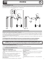 7
7
-
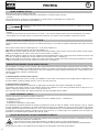 8
8
-
 9
9
-
 10
10
-
 11
11
-
 12
12
-
 13
13
-
 14
14
-
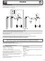 15
15
-
 16
16
-
 17
17
-
 18
18
-
 19
19
-
 20
20
-
 21
21
-
 22
22
-
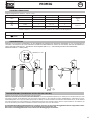 23
23
-
 24
24
-
 25
25
-
 26
26
-
 27
27
-
 28
28
-
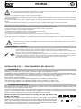 29
29
-
 30
30
-
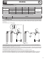 31
31
-
 32
32
-
 33
33
-
 34
34
-
 35
35
-
 36
36
-
 37
37
-
 38
38
-
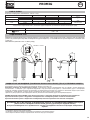 39
39
-
 40
40
-
 41
41
-
 42
42
-
 43
43
-
 44
44
-
 45
45
-
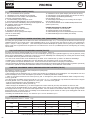 46
46
-
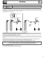 47
47
-
 48
48
-
 49
49
-
 50
50
-
 51
51
-
 52
52
-
 53
53
-
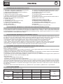 54
54
-
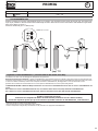 55
55
-
 56
56
-
 57
57
-
 58
58
-
 59
59
-
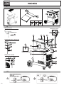 60
60
-
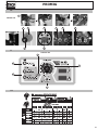 61
61
-
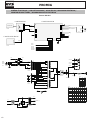 62
62
-
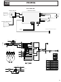 63
63
-
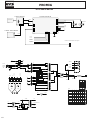 64
64
-
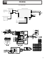 65
65
-
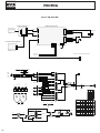 66
66
-
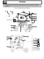 67
67
-
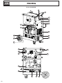 68
68
-
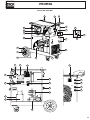 69
69
-
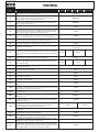 70
70
-
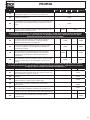 71
71
-
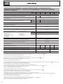 72
72
-
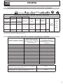 73
73
-
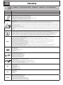 74
74
-
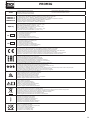 75
75
-
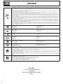 76
76


GYS PROMIG 400 4S El manual del propietario
- Categoría
- Sistema de soldadura
- Tipo
- El manual del propietario
- Este manual también es adecuado para
en otros idiomas
- français: GYS PROMIG 400 4S Le manuel du propriétaire
- italiano: GYS PROMIG 400 4S Manuale del proprietario
- Deutsch: GYS PROMIG 400 4S Bedienungsanleitung
- Nederlands: GYS PROMIG 400 4S de handleiding
Artículos relacionados
-
GYS Separate wire feeder WS-4R El manual del propietario
-
-
GYS UNIVERSAL COOLING UNIT MULTICOOL 1300 El manual del propietario
-
GYS MIG M1 GYS AUTO EQUIPE El manual del propietario
-
-
-
GYS PROMIG 400 4S Ficha de datos
-
-
GYS NEOPULSE 400 G El manual del propietario
-