
STEAM
DRYERStm
TOcontact LG Electronics, 24 hours a day,
7 days a week:
1-800-243-0000
Or visit us on the Web at: us.lge.com
NQmero telef6nico de LG Electronics, las 24
horas del dia, 7 dias a la semana:
1-800=243=0000
O visitenos en la Web en: us.lge.com
USER'SGUIDE&
INSTAllATIONINSTRUcTIoNS
Before beginning installation, read these
instructions carefully. This will simplify installation
and ensure that the dryer is installed correctly and
safely. Leave these instructions near the dryer
after installation for future reference.
STEAMDRYERStM
Secadorcon vapor
GU|ADE[ USUABIOE
INSTBUCCiONESDEINSTA[ACiON
Antes de comenzar la instalacion, lea atentamente
estas instrucciones. Esto simplificara la instalacion
Vasegurara que la secadora esta instalada
en forma correcta V segura. Conserve estas
instrucdones cerca de la secadora luego de la
instalacion para futuras consultas.
Models/Modelos
Eiectric/Electrica Gas/Gas
DLEX3001W
DLEX3001R
DLEX3001P
DLGX3002W
DLGX3002R
DLGX3002P
Protocol P154
Sanitization Performance ot: Residetiai
Clothes dryer
Protoco[o P154
Ejecucion de Saneamiento en [a zona
residential Secadoras
P/No. 3828EL3010N

INTP,ODUCIION
IMPORTANT SAFETY INSTRUCTIONS
Basic Safety Precautions ....................................... 3
What to Do if You Smell Gas .................................. 4
California safe drinking water and toxic
enforcement act .................................................... 4
Grounding Instructions ........................................... 5
Safety Instructions for Installation ...................... 5, 6
Safety Instructions for Steam Functions ................ 6
Safety Instructions for Connecting Electricity ....... 7
PARTS AND FEATURES
Special Features ..................................................... 8
Key Parts and Components ................................... 9
INSTALLATION INSTRUCTIONS
IMPORTANT: Read all installation instructions
completely before installing and operating your
dryer! ................................................................... 10
Choose the Proper Location ................................ 10
Clearances ........................................................... 10
Installation With Optional
Pedestal Base or Stacking Kit .............................. 11
Optional Accessories ......................................... 11
Leveling the Dryer ................................................ 12
Reversing the Door Swing .................................... 12
Changing the Dryer Vent Location ....................... 13
Venting the Dryer ............................................ 14, 15
Connecting Gas Dryers .................................. 16, 17
Connecting Electric Dryers ............................. 18-22
Special Requirements for Manufactured
or Mobile Homes .................................................. 23
Final Installation Check ....................................... 23
Flow Check (Duct condition test) ......................... 24
HOW TO USE
Sorting Loads ....................................................... 25
Loading the Dryer ................................................. 25
Check the Lint Filter Before Every Load ............... 25
Control Panel Features ......................................... 26
Cycle Guide .......................................................... 27
The LCD Display ............................................. 28, 29
Operating the Dryer .............................................. 30
Cycle Setting Buttons .......................................... 30
Cycle Option Buttons .......................................... 31
Special Functions ................................................. 32
Custom Program .................................................. 33
Steam Functions ............................................ 33-35
Steam Cycle Guide .............................................. 35
USER MAINTENANCE INSTRUCTIONS
Regular Cleaning .................................................. 36
f_
THANKYOU!
Oongratulations on your purchase
and welcome to the LG family. Your
new LG Dryer combines the most
advanced drying sensor technology
with simple operation and high
efficiency. By following the
operating and care instructions
in this manual, your dryer will
provide you with many years of
reliable service.
OPTIONAL ACCESSORIES/
SPECIFICATIONS
Optional Accessories ........................................... 40
Pedestal Installation ....................................... 41, 42
Stacking Kit Installation .................................. 43, 44
Key Dimensions and Specifications ..................... 44
_WARRANTY ...................................................45
TROUBLESHOOTING
BeforeCallingforService...............................37-39
2

iMPORTANTSAFETYiNSTRUCTiONS
READ ALL iNSTRUCTiONS BSFORE USE
WARNING For your safety,the information in this manual must be
followed to minimize the risk of fire or explosion, electric shock, or to prevent
property damage, personal injury, or loss of life.
Your Safety and the safety of others is very important.
We have provided many important safety messages in this manual and on your appliance. Always read
and obey all safety messages.
This isthe safety alert symbol.
This symbol alerts you to potential hazards that can kill or hurt you and others.
All safety messages will follow the safety alert symbol and either the word DANGER or WARNING.
These words mean:
_DANGER: You can be killed or seriously injured if you don't immediately follow instructions.
_WARN|_G: You can be killed or seriously injured ifyou don't follow instructions.
All safety messages will tell you what the potential hazard is, tell you how to reduce the chance of
injury, and tell you what can happen if the instructions are not followed.
BASIC SAFETY PRECAUTIONS
WARNING=
appliance, follow basic precautions, including the following:
• Read all instructions before using the dryer.
Before use, the dryer must be properly installed
as described in this manual.
Do not place items exposed to cooking oils in
your dryer. Items contaminated with cooking
oils may contribute to a chemical reaction that
could cause a load to catch fire.
Do not dry articles that have been previously
cleaned in, washed in, soaked in, or spotted
with gasoline, dry-cleaning solvents, or other
flammable or explosive substances as they give
off vapors that could ignite or explode.
• Do not reach intothe dryer if the drum or any
other part is moving.
Do not repair or replace any part of the dryer
or attempt any servicing unless specifically
recommended in this Use and Care Guide or
in published user-repair instructions that you
understand and have the skills to carry out.
• Do not tamper with controls.
Before the dryer is removed from service or
discarded, remove the door to the drying
compartment.
To reduce the risk of fire, electric shock, or injury to persons when using this
Do not allow children to play on or in the dryer.
Close supervision of children is necessary when
the dryer is used near children.
Do not use fabric softeners or products to
eliminate static unless recommended by the
manufacturer of the fabric softener or product.
Do not use heat to dry articles containing
foam rubber or similarly textured rubber-like
materials.
Keep area around the exhaust opening and
adjacent surrounding areas free from the
accumulation of lint, dust, and dirt.
The interior of the dryer and exhaust vent
should be cleaned periodically by qualified
service personnel.
Do not install or store the dryer where it will be
exposed to the weather.
Always check the inside of the dryer for foreign
objects.
Clean lint screen before or after each load.
5

I PORTANTSAFETYiNSTRUcTiONS
R_:AD ALL iNSTRUCTiONS BI=FORI: USS
_WARNING For your safety,the information in this manual must be
followed to minimize the risk of fire or explosion, electric shock, or to prevent
property damage, personal injury, or loss of life.
• Do not store or use gasoline or other
flammable vapors and liquids in the
vicinity of this appliance or any other
appliances.
• installation and service must be
performed by a qualified installer,
service agency, or the gas supplier.
WHAT TO DO IF YOU SMELL GAS:
1. Do not try to light a match or cigarette,
or turn on any gas or electrical
appliance.
2. Do not touch any electrical switches.
Do not use any phone in your building.
3. Clear the room, building, or area of all
occupants.
4. Immediately call your gas supplier
from a neighbor's phone. Follow the
gas supplier's instructions carefully.
5. It=you cannot reach your gas
supplier, call the fire department.
CALiFORNiA SAFE DRINKING WATER AND TOXIC ENFORCEMENT ACT
This act requires the governor of California to publish a list of substances known to the state to cause
cancer, birth defects, or other reproductive harm and requires businesses to warn customers of potential
exposure to such substances.
Gas appliances can cause minor exposure to four of these substances, namely benzene, carbon monoxide,
formaldehyde, and soot, caused primarily by the incomplete combustion of natural gas or LP fuels.
Properly adjusted dryers will minimize incomplete combustion. Exposure to these substances can be
minimized further by properly venting the dryer to the outdoors.
4

iMPORTANTSAFETYiNSTRUCTiONS
READ ALL iNSTRUCTiONS BSFORE USE
,WARNING For your safety,the information in this manual must be
followed to minimize the risk of fire or explosion, electric shock, or to prevent
property damage, personal injury, or loss of life.
GROUNDING iNSTRUCTiONS
This appliance must be grounded. In the event
of malfunction or breakdown, grounding will
reduce the risk of electric shock by providing
a path of least resistance for electric current.
This appliance must be equipped with a cord
having an equipment-grounding conductor and
a grounding plug. The plug must be plugged into
an appropriate outlet that is properly installed and
grounded in accordance with all local codes and
ordinances.
WARNING-Improper
connection of the equipment=grounding
conductor can result in a risk of electric shock.
Check with a qualified electrician or service
person if you are in doubt as to whether the
appliance is properly grounded.
Do not modify the plug provided with the
appliance. If it will not fit the outlet, have a proper
outlet installed by a qualified electrician.
This appliance must be connected to a grounded
metal, permanent wiring system or an equipment-
grounding conductor must be run with the circuit
conductors and connected to the equipment-
grounding terminal or lead on the appliance.
Electrical shock can result if the dryer is not
properly grounded.
SAFETY iNSTRUCTiONS FOR iNSTALLATiON
WARNING: To reduce the risk of fire, electric shock, or injury to persons when using this
appliance, follow basic precautions, including the following:
• Properly ground dryer to conform with all
governing codes and ordinances. Follow
details in the installation instructions. Electrical
shock can result if the dryer is not properly
grounded.
• Before use, the dryer must be properly
installed as described in this manual.
Electrical shock can result if the dryer is not .
properly grounded.
• install and store the dryer where it will not be
exposed to temperatures below freezing or
exposed to the weather.
, All repairs and servicing must be performed
by an authorized servicer unless specifically ,
recommended in this Owner's Guide. Use
only authorized factory parts. Failure to follow
this warning can cause serious injury, fire,
electrical shock, or death.
• To reduce the risk of electric shock, do not
install the dryer in humid spaces. Failure to
follow this warning can cause serious injury, fire,
electrical shock, or death.
Connect to a properly rated, protected,
and sized power circuit to avoid electrical
overload, improper power circuit can melt,
creating electrical shock and/or fire hazard.
Remove all packing items and dispose of all
shipping materials properly. Failure to do so
can result in death, explosion, fire, or burns.
Place dryer at least 18 in. above the floor
for a garage installation. Failure to do so can
result in death, explosion, fire, or burns.
Keep all packaging from children. Packaging
material can be dangerous for children. There is
a risk of suffocation.
Do not install nearby heat item. Such as
stove, cooking oven. Failure to do so can cause
deform, smoke and fire.
Do not place candle and cigarettes on top of
the product. Failure to do so can cause deform,
smoke and fire.
Remove all protective vinyl film from the
product. Failure to do so can cause deform,
smoke and fire.
5

I PORTANTSAFETYiNSTRUcTiONS
R :AD ALL iNSTRUCTiONS BI=FORI= USS
WARNING For your safety,the information in this manual must be
followed to minimize the risk of fire or explosion, electric shock, or to prevent
property damage, personal injury, or loss of life.
SAFETY iNSTRUCTiONS FOR iNSTALLATiON
Exhaust/Ducting:
• Gas dryers MUST be exhausted to the
outside. Failure to follow these instructions
can result in fire or death.
• The dryer exhaust system must be exhausted
to the outside of the dwelling, if the dryer is
not exhausted outdoors, some fine lint and
large amounts of moisture will be expelled
into the laundry area. An accumulation of
lint in any area of the home can create a health
and fire hazard.
• Use only rigid metal or flexible metal 4=in.
diameter ductwork inside the dryer cabinet
or for exhausting to the outside. Use of
plastic or other combustible ductwork can
cause a fire. Punctured ductwork can cause
a fire if itcollapses or becomes otherwise
restricted in use or during installation.
• Ductwork is not provided with the dryer, and
you should obtain the necessary ductwork
locally. The end cap should have hinged
dampers to prevent backdraft when the dryer
is not in use. Failure to follow these instructions
can result in fire or death.
• The exhaust duct must be 4 in. (10 cm) in
diameter with no obstructions. The exhaust
duct should be kept as short as possible.
Make sure to clean any old ducts before
installing your new dryer. Failure to follow
these instructions can result in fire or death.
• Rigid or semi rigid metal ducting is
recommended for use between the
dryer and the wall. in special installations
when it is impossible to make a connection
with the above recommendations, a UL-
listed flexible metal transition duct may be
used between the dryer and wall connection
only. The use of this ducting will affect drying
time. Failure to follow these instructions can
result in fire or death.
• DO NOT use sheet metal screws or other
fasteners which extend into the duct that
could catch lint and reduce the efficiency
of the exhaust system. Secure all joints with
duct tape. For complete details, follow the
installation Instructions. Failure to follow these
instructions can result in fire or death.
SAFETY INSTRUCTIONS FOR STEAM FUNCTIONS
WARNING: To reduce the risk of fire, electric shock, or injury to persons when using this
appliance, follow basic precautions, including the following:
Do not open the dryer door during steam
cycles. Failure to follow these instructions can
result in a burn hazard.
Do not dry articles that have been previously
cleaned in, washed in, soaked in, or spotted
with gasoline, dry=cleaning solvents, or other
flammable or explosive substances as they
give off vapors that could ignite or explode.
Failure to follow these instructions can result in
fire or death.
• Do not fill the steam feeder with gasoline,
dry=cleaning solvents, or other flammable or
explosive substances. Failure to follow these
instructions can result in fire or death.
• Do not touch the steam nozzle in the drum
during or after the steam cycle. Failure to
follow these instructions can result in a burn
hazard.
• Do not fill the steam feeder with hot water
(over 86°F/30°0). Failure to follow these
instructions can result in a burn hazard.
6

iMPORTANTSAFETYiNSTRUCTiONS
READ ALL INSTRUCTIONS BEFORE USE
WARNING For your safety,the information in this manual must be
followed to minimize the risk of fire or explosion, electric shock, or to prevent
property damage, personal injury, or loss of life.
SAFETY iNSTRUCTiONS FOR CONNECTING ELECTRiCiTY
WARNING: To reduce the risk of fire, electric shock, or injury to persons when using this
appliance, follow basic precautions, including the following:
, Do not, under any circumstances, cut or
remove the ground prong from the power
cord. To prevent personal injury or damage to
the dryer, the electrical power cord must be
plugged into a properly grounded outlet.
, For personal safety, this dryer must be
properly grounded. Failure to do so can result
in electrical shock or injury.
• Refer to the installation instructions in this
manual for specific electrical requirements
for your model. Failure to follow these
instructions can create an electrical shock
hazard and/or a fire hazard.
• This dryer must be plugged into a properly
grounded outlet. Electrical shock can result if
the dryer is not properly grounded. Have the
wall outlet and circuit checked by a qualified
electrician to make sure the outlet is properly
grounded. Failure to follow these instructions
can create an electrical shock hazard and/or a
fire hazard.
• The dryer should always be plugged into
its own individual electrical outlet which
has a voltage rating that matches the rating
plate. This provides the best performance
and also prevents overloading house wiring
circuits which could cause a fire hazard from
overheated wires.
, Never unplug your dryer by pulling on the
power cord. Always grip plug firmly and pull
straight out from the outlet. The power cord
can be damaged, resulting in a risk of fire and
electrical shock.
• Repair or replace immediately all power
cords that have become frayed or otherwise
damaged. Do not use a cord that shows
cracks or abrasion damage along its length
or at either end. The power cord can melt,
creating electrical shock and/or fire hazard.
• When installing or moving the dryer, be
careful not to pinch, crush, or damage
the power cord. This will prevent injury and
prevent damage to the dryer from fire and
electrical shock.
SAVE THESE INSTRUCTIONS
7

PARTSAND FEATU ES
SPECIAL FEATURES
O EASY-TO-USE CONTROL PANEL
Rotate the Cycle Selector Knob to select the
desired dry cycle. Add cycle options or adjust
settings with the touch of a button.
EASY=ACCESS REVERSIBLE DOOR
Wide-opening door provides easy access for
loading and unloading. Door swing can be
reversed to adjust for installation location.
ULTRA=CAPACITY STAINLESSSTEEL DRUM
WITH DRUM LIGHT
The ultra-large stainless steel drum offers
superior durability. The drum is equipped with a
yellow light that illuminates when the dryer door
is open and turns off when the door is closed.
O
O
O
HELPFUL STEAM FUNCTIONS
LG's new steam technology allows you to inject
fabrics with a swirling jet of hot steam to refresh
clothes, reduce static, and make ironing easier.
Simply select the STEAMFRESH TM cycle, or you
can add a Steam option to selected cycles.
LCD DISPLAY SCREEN
The easy-to-read LCD screen shows cycle
options and information and provides status
messages during operation.
FLOWSENSE TM DUCT/FILTER BLOCKAGE
SENSING SYSTEM
The FLOWSENSE TM duct/filter blockage sensing
system detects and alerts you to blockages in the
filter and ductwork that reduce exhaust flow from
the dryer. This improves operating efficiency and
help minimize service calls, saving you money.
8

PARTSANDFEATURES
KEY PARTS AND COMPONENTS
Inadditiontothespecialfeaturesandcomponentsoutlinedin
theSpecialFeaturessection,thereareseveralotherimportant
componentsthatarereferencedinthismanual.
O
FRONT-MOUNT LINT FILTER
Front-mounted lint filter allows for easy access
and cleaning after every load.
O LEVELING FEET
Four leveling feet (two in the front, and two in the back)
adjust to improve dryer stability on uneven floors,
O
DRYING RACK
Usethe dryingrack with the RACKDRYcycle option. The
dryingrack allows items,such assweaters,delicates,and
gym shoes,to be placedina flat position fordrying.
Power Cord Location
(Gas Models)
Terminal Block
Access Panel
(Electric Models)
Gas
Connection
Location
(Gas Models)
Exhaust Duct
Outlet
Rear of Dryer
Included Accessories
O
Drying Rack
9

INSTA[[ATIONINST UcTIONS
IMPORTANT: Read all installation instructions completely before
installing and operating your dryer!
It is important that you review this entire manual before installing and using your dryer. Detailed instructions
concerning electrical connections, gas connections, and exhaust requirements are provided on the
following pages.
CHOOSE THE PROPER LOCATION
• Store and install the dryer where it will not be
exposed to temperatures below freezing or
exposed to outdoor weather conditions.
• Choose a location with a solid, level floor.
If the dryer is being installed in a garage,
place the dryer at least 18 in. (46 cm) above
the floor.
• Properly ground dryer to conform with all
governing codes and ordinances.
To reduce the risk of electric shock, do not
install the dryer in damp or wet locations.
If you are installing your dryer in a manufactured
or mobile home, please refer to the section
Special Requirements for Manufactured or
Mobile Homes.
CLEARANCES
_22.4"_
(56.8 mm)
(76.1 cm) (10 cm)
51"_
(129.7mm)
olo
1"-_1I-._ 27"_ _1"
(2.54 cm) (68.6 cm) (2.54 cm)
3"
(7.6 cm)
48 in. 2
(310 cm 2)
24 in.2
(155 cm 2)
....
0
T Closet Door Vent
3"
(7.6 crn) Requirements
• Most installations require a minimum 51/2in.
(14 cm) clearance behind the dryer for the
exhaust ducting.
Allow minimum clearances of at least 1 in.
(2.5 cm) on the sides and back to minimize
vibration and noise.
Allowing additional clearance for installation and
servicing is recommended.
Be sure to allow for wall, door, or floor moldings
that may increase the required clearances.
Allow at least 24 in. (61 cm) in front of the dryer
to open the door.
Additional Instructions for closet installations:
The closet door must allow for sufficient airflow.
Refer to the diagram above for minimum vent
opening requirements. A Iouvered door is also
acceptable.
Make sure that there isat least 18 in. (46 cm) of
clearance above the dryer.
10

iNSTALLATiONINSTRU€TIONS
iNSTALLATiON WITH OPTIONAL
PEDESTAL BASE OR STACKING KiT
iMPORTANT: If you are installingyour dryer
using an optional pedestal base or stacking
kit, please refer to Optional Accessories in this
manual or to the instructions for your pedestal
or stacking kit before proceeding with the
installation.
Required Dimensions for Installation
With Pedestal
Required Dimensions for Installation
With Stacking Kit
iiii
i i /_
m |'
I_ 30"_1 I-._4"
(76.1 cm) (10 cm)
771/2''
(196.8 cm)
1"-_1I_ 27" _ _t-l"
(2.54 cm) (68.6 cm) (2.54 cm)
OPTIONAL ACCESSORIES
For these and other LG products, contact your local LG dealer, or visit our Web site at us.lge.com.
S
Pedestal (sold separatelW
i _
Stacking Kit (sold separatelW
11

INSTAllATION INST UcTIONS
LEVELING THE DRYER
, ,WARNING
• Weargloves during installation.
• Failureto follow these instructions can result in injury.
To ensure that the dryer provides optimal drying
performance, it must be level. To minimize
vibration, noise, and unwanted movement, the
floor must be a perfectly level, solid surface.
NOTE: Adjust the leveling feet only as far as
necessary to level the dryer. Extending the
leveling feet more than necessary can cause
the dryer to vibrate.
• All four leveling feet must rest solidly on the
floor. Gently push on the top corners of the
dryer to make sure that the dryer does not
rock from corner to corner.
If you are installing the dryer on the optional
pedestal, you must use the leveling feet on the
pedestal to level the dryer. The dryer leveling feet
should be fully retracted.
Leveling Feet
Position the dryer in the final location. Place
a level across the top of the dryer.
Use an adjustable wrench to turn the leveling
feet. Turn clockwise to raise the dryer or
counterclockwise to lower it. Raise or lower
the leveling feet until dryer is level from
side to side and front to back.
Make sure that all 4 leveling feet are in firm
contact with the floor.
12
REVERSING THE DOOR SWING
The swing of the dryer door can be reversed to fit your installation location.
Latch Screws
\
\_\ \\ \
\\
/%
tinge "_
Screws
_,,,J
Open the dryer door. Using a Phillips
screwdriver, remove the 4 screws that secure
the door hinge to the dryer door opening.
Remove the 6 screws from the latch side of the
dryer door opening, and remove the door latch.
\\
,/Hinge
Screws
Turn the door around so the hinge is
reversed, and reattach the door using the
4 screws previously removed. Reinstall the
door latch and the 6 screws.
Test the door swing to make sure the door
moves freely and latches securely.

INSTALLATIONINSTRU€TIONS
CHANGING THE DRYER VENT LOCATION
WARNING
• Use a heavy metal vent.
• Do not use plastic or thin foil duct.
• Clean old ducts before installing this dryer.
• Weargloves during installation.
• Failureto follow these instructions can result in death
or fire.
Your new dryer is shipped to vent to the rear.
it can also be configured to vent to the bottom
or side (right-side venting is not available on
gas models).
An adapter kit, part number 383EEL9001B,
may be purchased from your LG retailer. This
kit contains the necessary duct components
to change the dryer vent location.
Retaining
Screw
Rear
Exhaust Duct
...... J
Remove the rear exhaust duct retaining
screw. Pull out the exhaust duct.
OPTION 1: Side venting
Adapter _,.
Duct _
Pressthetabsonthe knockoutandcarefullyremovethe
knockoutforthedesiredventopening(right-sideventing
is notavailableongasmodels).Presstheadapterduct
ontothe blowerhousingandsecuretothebaseofthe
dryerasshown.
Plate
Elbo_
Preassemblea4-in.(10cm)elbowtothenext4-in.(10cm)
ductsection,andsecurealljointswithducttape.Besure
thatthemaleendoftheelbowfacesAWAYfromthedryer.
Inserttheelbow/ductassemblythroughthesideopening
andpressitontotheadapterduct.Securein placewith
ducttape.
Besurethatthemaleendd theductprotrudes11/2in.(3.8
cm)toconnecttheremainingductwork.
Attachcoverplatetothebackofthedryerwithincluded
screw,
OPTION 2: BOttOm venting
Adapter
Bracket
Press the adapter duct onto the blower
housing and secure to the base of the dryer
as shown.
Plate
............................................................................................................................................................................................................................................................................................................................................................................................................................j
insert the 4-in. (10 cm) elbow through the
rear opening and press it onto the adapter
duct. Be sure that the male end of the elbow
faces down through hole in the bottom of the
dryer. Secure in place with duct tape.
Attach the cover plate to the back of the
dryer with included screw.
15

INSTAllATION INST UcTIONS
VENTING THE DRYER
WARN|NG: To reduce the risk of fire, electric shock, or injury to persons when using this
appliance, follow basic precautions, including the following:
• Do not crush or collapse ductwork. Failure
to follow these instructions can result in fire
or death.
• Do not allow ductwork to rest on or
contact sharp objects. Failure to follow these
instructions can result in fire or death.
• if connecting to existing ductwork, make
sure it is suitable and clean before installing
the dryer. Failure to follow these instructions
can result in fire or death.
Venting must conform to local building
codes. Failure to follow these instructions can
result in fire or death.
Gas dryers MUST exhaust to the outdoors.
Failure to follow these instructions can result
in fire or death.
• Use only 4=in. (10 cm) rigid or flexible metal
ductwork inside the dryer cabinet and
for venting outside. Failure to follow these
instructions can result in fire or death.
To reduce the risk of fire, combustion, or
accumulation of combustible gases, DO
NOT exhaust dryer air into an enclosed and
unventilated area, such as an attic, wall,
ceiling, crawl space, chimney, gas vent, or
concealed space of a building. Failure to
follow these instructions can result infire
or death.
To reduce the risk of fire, DO NOT exhaust
the dryer with plastic or thin foil ducting.
Failure to follow these instructions can result
in fire or death.
• The exhaust duct must be 4 in. (10 cm) in
diameter with no obstructions. The exhaust
duct should be kept as short as possible.
Make sure to clean any old ducts before
installing your new dryer. Failure to follow
these instructions can result in fire or death.
• Rigid or semirigid metal ducting is
recommended for use between the dryer
and the wall. in special installations when
it is impossible to make a connection with
the above recommendations, a UL=listed
flexible metal transition duct may be used
between the dryer and wall connection only.
The use of this ducting will affect drying
time. Failure to follow these instructions can
result in fire or death.
DO NOT use sheet metal screws or other
fasteners which extend into the duct that
could catch lint and reduce the efficiency
of the exhaust system. Secure all joints
with duct tape. Failure to follow these
instructions can result in fire or death.
• TOmaximize operating results, please
observe the duct length limitations noted in
the chart on page 15. Failure to follow these
instructions can result in fire or death.
• Ductwork is not provided with the dryer.
You should obtain the necessary ductwork
locally. The end cap should have hinged
dampers to prevent backdraft when the
dryer is not in use. Failure to follow these
instructions can result in fire or death.
14

INSTALLATIONINSTRU€TIONS
VENTING THE DRYER (cont.)
DuCtwOrk
0 65 ft. (19.8 m) 45 ft. (13.7 m)
Recommended
1 55 ft. (16.8 m) 35 ft. (10.7 m)
_---_ 2 47 ft. (13.7 m) 30 ft. (9.1 m)3 36 ft. (11.0 m) 25 ft. (7.6 m)
/_o_om/ /_o_om/ 4 28 ft. (8.5 m) 20 ft. (6.1 m)
Use Only for Short 0 55 ft. (16.8 m) 35 ft. (10.7 m)
Run Installations 1 47 ft. (13.7 m) 27 ft. (8.1 m)
__ 2 41 ft. (12.5 m) 21 ft. (6.4 m)
3 30 ft. (9.1 m) 17 ft. (5.2 m)
(6.35 ore)
,,,, 4 22 ft. (6.7 m) 15 ft. (4.5 m)
.y
NOTE: Deduct 6 ft. (1.8 m) for each additional elbow. It is not recommended to use more than four 90° elbows.
ROuting and Connecting Ductwork
Follow the guidelines below to maximize drying
performance and reduce lint buildup and
condensation in the ductwork.
NOTE: Ductwork and fittings are NOT included
and must be purchased separately.
• Use 4-in. (10 cm) diameter rigid or semirigid
metal ductwork.
The exhaust duct run should be as short as
possible.
Use as few elbow joints as possible.
The male end of each section of exhaust duct
must point away from the dryer.
Use duct tape on all duct joints.
Insulate ductwork that runs through unheated
areas in order to reduce condensation and lint
buildup on duct surfaces.
iMPORTANT: Failure to exhaust the dryer
correctly will void the dryer's warranty.
Correct Venting
incorrect Venting
15

INSTAllATION INST UcTIONS
CONNECTING GAS DRYERS
_I_WARN|NG: To reduce the risk of fire, electric shock, or injury to persons when using this
appliance, follow basic precautions, including the following:
= Gas supply requirements:
As shipped from the factory, this dryer is
configured for use with natural gas. It can be
converted for use with LP (Liquefied Propane)
gas. Gas pressure must not exceed 13 in.
water column.
= A qualified service or gas company technician
must connect the dryer to the gas service.
Failure to do so can result in fire, explosion,
or death.
, Isolate the dryer from the gas supply system
by closing its individual manual shutoff valve
during any pressure testing of the gas supply.
Failure to do so can result in fire, explosion,
or death.
, Supply line requirements:
Your laundry room must have a rigid gas
supply line to your dryer, in the United States,
an individual manual shutoff valve MUST be
instafled within at least 6 ft. (1.8 m) of the dryer,
in accordance with the National Fuel Gas Code
ANS! Z223.1 or Canadian gas installation code
CSA B149.1. A 1/8-in. NPT pipe plug must
be installed. Failure to do so can result in fire,
explosion, or death.
, If using a rigid pipe, the rigid pipe should be
1/2-in. IPS. If acceptable under local codes
and ordinances and when acceptable to your
gas supplier, 3/8-in. approved tubing may be
used where lengths are less than 20 ft. (6.1
m). Larger tubing should be used for lengths
in excess of 20 ft. (6.1 m). Failure to do so can
result in fire, explosion, or death.
, Connect the dryer to the type of gas shown on
the nameplate. Failure to do so can result in fire,
explosion, or death.
, To prevent contamination of the gas valve,
purge the gas supply of air and sediment
before connecting the gas supply to the dryer.
Before tightening the connection between the
gas supply and the dryer, purge remaining air
until the odor of gas is detected. Failure to do
so can result in fire, explosion, or death.
, DO NOT use an open flame to inspect for gas
leaks. Use a noncorrosive leak-detection fluid.
Failure to do so can result in fire, explosion, or
death.
, Use onJy a new AGA- or CSA-certified gas
suppJy line with flexible stainless steel
connectors. Failure to do so can result in fire,
explosion, or death.
, Securely tighten all gas connections. Failure
to do so can result in fire, explosion, or death.
, Use Teflon ®tape or a pipe-joint compound that
is insoluble in Liquefied Petroleum (LP) gas on
all pipe threads. Failure to do so can result in fire,
explosion, or death.
, DO NOT attempt any disassembly of the dryer;
any disassembly requires the attention and
tools of an authorized and qualified service
person or company. Failure to do so can result
in fire, explosion, or death.
Electrical Requirements for Gas MOdelS Only
,WARN|NG" To reduce the risk of fire, electric shock, or injury to persons when using this
appliance, follow basic precautions, including the following:
o Do not, under any circumstances, cut or
remove the third (ground) prong from the power
cord. Failure to follow this warning can result in
fire, explosion, or death.
o For personal safety, this dryer must be properly
grounded. Failure to follow this warning can result
in fire, explosion, or death.
The power cord of this dryer is equipped with
a 3-prong (grounding) plug which mates with
a standard 3-prong (grounding) wall outlet
to minimize the possibility of electric shock
hazard from this appliance. Failure to follow this
warning can result in fire, explosion, or death.
, This dryer must be plugged into a
120-VAC, 60=Hz. grounded outlet protected by
a 15-ampere fuse or circuit breaker. Failure to
follow this warning can result in fire, explosion,
or death.
, Where a standard 2-prong waft outlet is
encountered, it is your personal responsibility
and obligation to have it replaced with a
properly grounded 3-prong wall outlet. Failure
to follow this warning can result in fire, explosion,
or death.
16

INSTALLATIONINSTRU€TIONS
CONNECTING GAS DRYERS (cont.)
WARNING:
appliance, follow basic precautions, including the following:
• installation and service must be performed •
by a qualified installer, service agency, or the
gas supplier. Failure to do so can result in fire,
explosion, or death.
Use only a new stainless steel flexible
connector and a new AGA=certified
connector. Failure to do so can result in fire, =
explosion, or death.
A gas shutoff valve must be installed within
6 ft. (1.8 m) of the dryer. Failure to do so can
result in fire, explosion, or death.
• The dryer is configured for Natural Gas when
shipped from the factory. Make sure that the
dryer is equipped with the correct burner
nozzle for the type of gas being used (Natural
Gas or Liquefied Petroleum). Failure to do so
can result in fire, explosion, or death.
To reduce the risk of fire, electric shock, or injury to persons when using this
If necessary, the correct nozzle (for the LP
nozzle kit order part number 4948EL4002B)
should be installed by a qualified technician
and the change should be noted on the dryer.
Failure to do so can result in fire, explosion,
or death.
All connections must be in accordance with
local codes and regulations. Failure to do so
can result in fire, explosion, or death.
Gas dryers MUST exhaust to the outdoors.
Failure to do so can result in fire, explosion,
or death.
Connecting the Gas Supply
O Make sure that the gas supply to the laundry
room is turned OrE Confirm that the type
of gas available in your laundry room is
appropriate for the dryer. The dryer is
prepared for Natural Gas with a 3/8-in. NPT
gas connection.
O Remove the shipping cap from the gas
connection at the back of the dryer. Be
careful not to damage the threads of the gas
connector when removing the shipping cap.
t_ Connect the dryer to your laundry room's gas
supply using a new flexible stainless steel
connector with a 3/8-in. NPT fitting.
_ Securely all connections between the
tighten
dryer and your laundry room's gas supply.
Turn on your laundry room's gas supply and
check all pipe connections (both internal and
external) for gas leaks with a noncorrosive
leak-detection fluid.
Electrical Connection
Plug dryer into a
120=VAC, 60-Hz.
grounded 3-prong
outlet.
Stainless Steel
Flexible Connector
J
Hig#-Altitude Installations
The BTU rating of this dryer is AGA-certified for
elevations below 10,000 feet.
If your gas dryer is being installed at an elevation
above 10,000 feet, it must be derated by a
qualified technician or gas supplier.
17

INSTALLATIONINSTRUCTIONS
CONNECTING ELECTRIC DRYERS
• I_WARN|_II!_G -= To help prevent fire, electdc shock, serious injury,or death, the wiring and
grounding must conform to the latest edition of the National Electrical Code, ANSVNFPA 70 and all
applicable local regulations. Please contact a qualified electrician to check your home's wiring and
fuses to ensure that your home has adequate electrical power to operate the dryer.
Electrical Requirements for Electric MOdelS Only
WARNING: To reduce the risk of fire, electric shock, or injury to persons when using this
appliance, follow basic precautions, including the following:
• This dryer must be connected to a grounded •
metal, permanent wiring system, or an
equipment-grounding conductor must
be run with the circuit conductors and
connected to the equipment-grounding
terminal or lead on the dryer. Failure to do
so can result in fire, explosion, or death.
• The dryer has its own terminal block that
must be connected to a separate 240 VAC,
60-Hertz, single-phase circuit, fused at 30
amperes (the circuit must be fused on both
sides of the line). ELECTRICAL SERVICE
FOR THE DRYER SHOULD BE OF THE
MAXIMUM RATE VOLTAGE LISTED ON THE
NAMEPLATE. DO NOT CONNECT DRYER TO
110=, 115-, OR 120-VOLT CIRCUIT. Heating
elements are available for field installation
in dryers which are to be connected to an •
electrical service of a different voltage than
that listed on the rating plate. Failure to follow
these instructions can result in fire, explosion,
or death.
If branch circuit to dryer is 15 ft. (4.5 m)
or less in length, use UL (Underwriters
Laboratories) listed No.-10 AWG wire
(copper wire only), or as required by local
codes, if over 15 ft. (4.50 m), use UL-listed
No.-8 AWG wire (copper wire only), or as
required by local codes. Allow sufficient
slack in wiring so dryer can be moved from
its normal location when necessary. Failure
to do so can result in fire, explosion, or death.
The power cord (pigtail) connection between
wall receptacle and dryer terminal block
IS NOT supplied with dryer. Type of pigtail
and gauge of wire must conform to local
codes and with instructions on the following
pages. Failure to follow these instructions can
result in fire, explosion, or death.
A 4-wire connection is required for all mobile
and manufactured home installations, as
well as all new construction after January
1, 1996. A 4-wire connection must be used
where local codes do not permit grounding
through the neutral wire. Failure to do so can
result in fire, explosion, or death.
WARNING" To reduce the risk of fire, electric shock, or injury to persons when using this
appliance, follow basic precautions, including the following:
• DO not modify the plug and internal wire
provided with the dryer.
•The dryer should be connected to 4-hole outlet.
• If it does not fit the outlet, a proper outlet will
need to be installed by a qualified electrician.
Special Electrical Requirements for Mobile or Manufactured Homes
,WARNING" To reduce the risk of fire, electric shock, or injury to persons when using this
appliance, follow basic precautions, including the following:
• Any installation in a manufactured or mobile
home must comply with the Manufactured
Home Construction and Safety Standards
Title 24 CFR, Part 32-80 or Standard CAN/
CSA0Z240 MH and local codes and ordinances.
• A 4-wire connection is required for all mobile
and manufactured home installations, as well
as all new construction after January 1, 1996.
Failure to do so can result infire, explosion,
or death.
18

INSTAllATIONiNSTRUCTiONS
cONNEcTiNG ELEcTRic DRYERS {cont.)
USA ONLY
WARN|NG:
= Connect the power cord to the terminal block. Each colored wire should be connected
to same color screw. Wire color indicated on manual is connected to the same color
screw in block. Failure to follow these instructions may result in a short or overload.
= Grounding through the neutral conductor is prohibited for: (1) new branch-circuit
installations, (2) mobile homes, (3) recreational vehicles, and (4) areas where local
codes prohibit grounding through the neutral conductor.
Four-wire Connection for Electric Dryers: Power Cord
• A 4-wire connection is required for all mobile
and manufactured home installations, as well
as all new construction after January 1, 1996.
A UL-listed strain relief is required.
Use a 30-amp, 240V, UL=listed power cord
with #10 AWG=minimurn copper conductor
and closed loop or forked terminals with
upturned ends.
Terminal
Block
UL-Listed
Strain Relief
i UL-Listed
4-Wire
Power Cord
Remove the terminal block access cover
on the upper back of the dryer. Install a
UL-Iisted strain relief into the power cord
through-hole; then thread a UL-Iisted, 30A,
240V, 4-wire, #10 AWG=minirnurn copper
conductor power cord through the
strain relief.
J
Hot -- Neutral Hot
(Black) (White) (Red)
Ground Screw
Power
Ground Wire
Transfer the dryer's ground wire from behind
the green ground screw to the center screw
of the terminal block. Attach the two hot
leads of the power cord to the outer terminal
block screws. Attach the white neutral wire
to the center terminal block screw. Attach the
power cord ground wire to the green ground
screw. TIGHTEN ALL SCREWS SECURELY.
Reinstall the terminal block access cover.
19

INSTALLATIONINSTRUCTIONS
CONNECTING ELECTRIC DRYERS (cont.)
USA ONLY
WARN|NG:
. Connect the power cord to the terminal block. Each colored wire should be connected
to same color screw. Wire color indicated on manual is connected to the same color
screw in block. Failure to follow these instructions may result in a short or overload.
, Grounding through the neutral conductor is prohibited for: (1) new branch=circuit
installations, (2) mobile homes, (3) recreational vehicles, and (4) areas where local
codes prohibit grounding through the neutral conductor.
FOur-Wire Connection for Electric Dryers: Direct wire
• A 4-wire connection is required for all mobile
and manufactured home installations, as well
as all new construction after January 1, 1996.
• A UL-listed strain relief is required.
• Use UL-listed 4=wire #10 AWG=minimum
copper conductor cable.
• Allow at least 5 ft (1.5 m) length to allow for
removal and reinstallation of the dryer.
1" (2.5 cm)
I-4
Remove 5 inches (12.7 cm) of the outer
covering from the wire. Remove 5 inches
of insulation from the ground wire. Cut off
approximately 11/2inches (3.8 cm) from the
other three wires and strip 1 inch (2.5 cm)
insulation from each wire. Bend the ends of
the three shorter wires into a hook shape.
_J
Terminal
Block
UL-Listed
Strain Relief
"-,n
UL-Listed
4-Wire
Power Cord
Remove the terminal block access cover
on the upper back of the dryer. Install a
UL-listed strain relief into the power cord
through-hole; then thread the power cable
prepared in Step 1 through the strain relief.
Hot
(Black) (White) (Red)
Ground Wire
20
Transfer the dryer's ground wire from behind
the green ground screw to the center screw
of the terminal block. Attach the two hot
leads of the power cable to the outer terminal
block screws. Attach the white neutral wire
to the center terminal block screw. Attach the
power cable ground wire to the green ground
screw. TIGHTEN ALL SCREWS SECURELY.
Reinstall the terminal block access cover.

INSTALLATIONINSTRUCTIONS
CONNECTING ELECTRIC DRYERS {cont.)
USA ONLY
WARN|NG:
• Connect the power cord to the terminal block. Each colored wire should be connected
to same color screw. Wire color indicated on manual is connected to the same color
screw in block. Failure to follow these instructions may result in a short or overload.
• Grounding through the neutral conductor is prohibited for: (1) new branch-circuit
installations, (2) mobile homes, (3) recreational vehicles, and (4) areas where local
codes prohibit grounding through the neutral conductor.
_ Three-wire Connection for Electric Dryers: Power Cord
= A 3-wire connection is NOT permitted on new = Use a 30=amp, 240V, UL=listed power cord
construction after January 1, 1996. with #10 AWG=rninirnurn copper conductor
= A UL-listed strain relief is required, and closed loop or forked terminals with
upturned ends.
Terminal
Block
UL-Listed
Strain Relief
......... iii 3-Wi e
Power Cord
Remove the terminal block access cover
on the upper back of the dryer. Install a
UL-listed strain relief into the power cord
through-hole; then thread a UL-listed, 30A,
240V, 3=wire, #10 AWG-minirnurn copper
conductor power cord through the strain
relief.
...................... Hot
(Black) (White) (Red)
o
Ground Wire /
Attach the two hot leads of the power cord
to the outer terminal block screws. Attach
the neutral wire to the center terminal block
screw. Connect the external ground (if
required by local codes) to the green ground
screw. TIGHTEN ALL SCREWS SECURELY.
Reinstall the terminal block access cover.
21

INSTALLATIONINSTRUCTIONS
CONNECTING ELECTRIC DRYERS (cont.)
USA ONLY
WARN|NG:
. Connect the power cord to the terminal block. Each colored wire should be connected
to same color screw. Wire color indicated on manual is connected to the same color
screw in block. Failure to follow these instructions may result in a short or overload.
. Grounding through the neutral conductor is prohibited for: (1) new branch=circuit
installations, (2) mobile homes, (3) recreational vehicles, and (4) areas where local
codes prohibit grounding through the neutral conductor.
Three-wife Connection for Electric Dryers: Direct wire
• A 3-wire connection is NOT permitted on new • Use UL-listed 3=wire #10 AWG=rninimum
construction after January 1, 1996. copper conductor cable.
• A UL-listed strain relief is required. • Allow at least 5 ft (1.5 m) length to allow for
removal and reinstallation of the dryer.
1" (2.5 cm)
I-4
_J
Remove 31/2inches (8.9 cm) of the outer
covering from the wire. Strip 1 inch (2.5 cm)
insulation from each wire. Bend the ends of
the three wires into a hook shape.
Terminal
Block
UL-Listed
Relief
UL-Listed
3-Wire
Power Cord
Remove the terminal block access cover
on the upper back of the dryer. Install a
UL-listed strain relief into the power cord
through-hole; then thread the power cable
prepared in Step 1 through the strain relief.
............: 1:_:::: Hot Neutral Hot "_
Black) (White) (Red)
Ground Screw _ ..__1
......
Attach the two hot leads of the power cord
to the outer terminal block screws. Attach
the neutral wire to the center terminal block
screw. Connect the external ground (if
required by local codes) to the green ground
screw. TIGHTEN ALL SCREWS SECURELY.
Reinstall the terminal block access cover.
22

INSTAllATION INSTRUCTIONS
SPEciAL REQUIREMENTS FOR MANUFACTURED OR MOBILE HOMES
Any installation in a manufactured or mobile
home must comply with the Manufactured Home
Construction and Safety Standards Title 24 CFR,
Part 32-80 or Standard CAN/CSAOZ240 MH and
local codes and ordinances. If you are uncertain
whether your proposed installation will comply
with these standards, please contact a service
and installation professional for assistance.
• A gas dryer must be permanently attached to
the floor.
The electrical connection for an electric dryer
must be a 4-wire connection. More detailed
information concerning the electrical connection
is provided in the section Connecting Electric
Dryers.
To reduce the risk of combustion and fire, the
dryer must be vented to the outside.
DO NOT vent the dryer under a manufactured
home or mobile home.
Electric dryers may be vented to the outside
using the back, left, right, or bottom panel.
Gas dryers may be vented to the outside using
the back, left, or bottom panel. Gas dryers may
not be vented to the outside using the right side
panel because of the burner housing.
• The dryer exhaust duct must be affixed securely
to the manufactured or mobile home structure,
and the exhaust duct must be made of a
material that will resist fire and combustion.
It is recommended that you use a rigid or
flexible metal duct.
DO NOT connect the dryer exhaust duct
to any other duct, vent, chimney, or other
exhaust duct.
• Make sure the dryer has adequate access to
outside fresh air to ensure proper operation.
The opening for outside fresh air must be at
least 25 in2(163 cm2).
It is important that the clearance of the duct
from any combustible construction be at least
2 in. (5 cm), and when venting the dryer to
the outdoors, the dryer can be installed with a
clearance of 1 in. (2.5 cm) at the sides and back
of the dryer.
Please be aware that venting materials are
not supplied with the dryer. You should obtain
the venting materials necessary for proper
installation.
FINAL INSTALLATION CHECK
Once you have completed the installation of the dryer and it is in its final location, confirm proper operation
with the following tests and Duct Condition Testing on the following page.
Testing Dryer Heating
GAS MODELS
Close the dryer door, press the ON/OFF switch
to turn the dryer on, and start the dryer on a heat
setting. When the dryer starts, the igniter should
ignite the main burner.
NOTE: If all air is not purged from the gas line,
the gas igniter may turn off before the main
burner ignites. If this happens, the igniter will
reattempt gas ignition after approximately
two minutes.
ELECTRIC MODELS
Close the dryer door, press the ON/OFF switch
to turn the dryer on, and start the dryer on a heat
setting. The exhaust air should be warm after the
dryer has been operating for 3 minutes.
Checking Airflow
Effective dryer operation requires proper airflow.
The adequacy of the airflow can be measured
by evaluating the static pressure. Static pressure
in the exhaust duct can be measured with
a manometer, placed on the exhaust duct
approximately 2 ft. (60.9 cm) from the dryer.
Static pressure in the exhaust duct should not
exceed 0.6 in. (1.5 cm). The dryer should be
checked while the dryer is running with no load.
Checking Levelness
Once the dryer is in its final location, recheck
the dryer to be sure it is level. Make sure it is
level front to back and side to side, and that
all 4 leveling feet are firmly on the floor.
25

INSTAllATION INST UcTIONS
FLOW CHECK (DUCT CONDITION TEST)
Your dryer features FlowSense TM , an innovative
sensing system that automatically detects blockages
and restrictions in dryer ductwork. Keeping ductwork
clean of lint buildup and free of restrictions allows
clothes to dry faster and reduces energy use.
NOTE: When the dryer is first installed, this test
should be performed to alert you to any existing
problems with the exhaust duct in your home.
However, since the test performed during normal
operation provides more accurate information on
the condition of the exhaust duct than does the
installation test, the number of bars displayed during
the two tests may not bethe same.
To activate the flow check (Duct condition test} :
NOTE: Dryer heating test must be performed before
proceeding. Then perform the duct condition test
below:
t_ Press and hold the DAMP DRY BEEP and
TEMR CONTROL buttons at the same time.
While holding these buttons, press POWER
ON/OFR
O The display will show the FLOW CHECK start
screen.
O
Press START/PAUSE. The dryer
will run for approximately 2
minutes to test
for blockages
or restrictions
to air flow in the
ductwork.
COMPLETEDFLOWCHECK
If no bars are shown in
the display, the ductwork
is free from blockages
or restrictions.
NEEDFLOWCHECK
if all bars are lit, the
dryer ductwork has a
blockage that needs to
be removed immediately.
iMPORTANT: Do NOT interrupt the test cycle!
Correct Venting [_
Restricted or Blocked Airflow _=l
Avoid long runs or runs with multiple elbows
or bends.
Check for blockages and lint buildup.
Make sure the ductwork is not crushed
or restricted.
24 J

OWTO USE
Following are instructions for starting and using your new dryer. Please refer to specific sections of this
manual for more detailed information. Important warning: To reduce the risk of fire, electric shock,
or injury to persons, read this entire manual, including the important safety instructions, before
operating this dryer.
SORTING LOADS
FaDric Care LaDels
Most articles of clothing feature fabric care labels
that include instructions for proper care.
Grouping Similar Items
For best results, sort clothes into loads that can
be dried with the same drying cycle.
Different fabrics have different care
requirements, and some fabrics will dry
more quickly than others.
Fabric Care Labels
'u 'eFq D D
dry
Dry Normal PermanentPress/
wrinkle resistant
Donot dry
Gentle/ Donot tumble dry (usedwith
delicate do notwash)
,eat ® ®®
setting
High Medium Low No heat!air
LOADING THE DRYER
WARN|NG" To reduce the risk of fire, electric shock, or injury to persons when using this
appliance, follow basic precautions, including the following:
• Check all pockets to make sure that they are
empty. Items such as clips, pens, coins, and
keys can damage both your dryer and your
clothes. Flammable objects such as lighters
or matches could ignite, causing a fire.
Failure to do so can result in fire, explosion,
or death.
• Never dry clothes that have been exposed to
oil, gasoline, or other flammable substances.
Washing clothes will not completely remove
oil residues. Failure to obey this warning can
result in fire, explosion, or death.
Combine large and small items in a load.
Damp clothes will expand as they dry. Do not
overload the dryer; clothes require room to
tumble dry properly.
Close zippers, hooks, and drawstrings to
prevent these items from snagging or tangling
on other clothes.
CHECK THE LINT FILTER BEFORE EVERY LOAD
Always make sure the lint filter is clean before
starting a new load; a clogged lint filter will
increase drying times.
To clean, pull the lint filter straight up and roll any
lint off the filter with your fingers. Do not rinse or
wash the filter to remove tint. Push the lint filter
firmly back into place. See "Care and Cleaning"
for more information.
Always ensure the lint filter is properly installed
before running the dryer. Running the dryer with
a loose or missing lint filter may damage the
dryer and articles in the dryer.
f ....
Lint Filter
25

HOWTO USE
CONTROL PANEL FEATURES
Following are instructions for starting and using your new dryer. Please refer to specific sections
of this manual for more detailed information, important Warning: To reduce the risk of fire,
electric shock, or injury to persons, read this entire manual, including the important Safety
instructions, before operating this dryer.
e
0
26
O POWER ON/OFF BUTTON
Press to turn the dryer ON. Press again to
turn the dryer OrE
O
O
O
NOTE: Pressing the ON/OFF button during
a cycle will cancel that cycle and any load
settings will be lost.
CYCLE SELECTOR KNOB
Turn this knob to select the desired cycle.
Once the desired cycle has been selected, the
standard presets will be shown in the display.
On MANUAL DRY cycles, these settings can
be adjusted using the cycle settings buttons
anytime before starting the cycle.
START/PAUSE BUTTON
Press this button to START the selected
cycle. If the dryer is running, use this button
to PAUSE the cycle without losing the
current settings.
NOTE: if you do not press the START/PAUSE
button to resume a cycle within 4 minutes,
the dryer automatically turns off.
MORE TIME/LESS TiME BUTTONS
To adjust the drying time, use these buttons with
MANUAL DRY, TIME DRY, and STEAMFRESH TM
cycles, as well as the REDUCE STATIC and
EASY IRON options. Press the MORE TIME
button to increase the selected manual cycle
time by a minute; press LESS TIME to decrease
the cycle time by a minute.
O
O
O
CYCLE SETTING BUTTONS
Use these buttons to select the desired cycle
settings for the selected cycle. The current
settings are shown in the display. Press the
button for that option to view and select
other settings.
LCD DISPLAY
The display shows the settings, estimated
time remaining, options, and status
messages for your dryer.
OPTION BUTTONS
The OPTION buttons allow you to select
additional cycle options. Certain buttons
feature a special function (see the following
pages for details) that can be activated by
pressing and holding that option button.
HELPFUL STEAM FUNCTIONS
LG's new steam technology allows you
to inject fabrics with a swirling jet of hot
steam to refresh clothes, reduce static,
and make ironing easier. Simply select the
STEAMFRESH TM cycle, or you can add a
STEAM option to selected cycles.
For detailed information about the individual
options, please see the following pages.

OWTO USE
CYCLE GUIDE
The cycle guide below shows the options and recommended fabric types for each cycle.
STEAM
FRESHTM
STEAM
SANITARYTM
HEAVYDUTY
COTTON/
TOWELS
NORMAL
PERM.PRESS
DELICATES
SPEEDDRY
AIRDRY
TIMEDRY
RACKDRY
Comforter,Shirts, 20
Trousers(except Off MIDHIGH
especiallydelicatefabrics Adjustable
Comforter,Bedding, Off HiGH 39
children'sclothing
Jeans, Normal
heavyweightitems Adjustable
HiGH 54
Denims,towels, Normal
MIDHIGH 55
heavycottons Adjustable
Normal
Workclothes, MEDIUM 41
corduroys,etc. Adjustable
Permanentpress, Normal
LOW 36
syntheticitems Adjustable
Lingerie,sheets, Normal
blouses Adjustable
LOW 32
Forsmall loads HIGH 25
with short Off
dryingtimes Adjustable Adjustable
Foriremsthat 30
requireheat-free Off NoHeat
dryingsuchas
31asticsor rubber Adjustable
Forgeneraldrying; HIGH 40
time,temperature, Off
andoptionscanbe Adjustable Adjustable
setmanually
Off 50
Woolsweaters,
silk,lingerie Off ULTRALOW Adjustable
LOW
J
Sensor Dry Cycles
Sensor Dry cycles utilize LG's unique dual sensor
system to detect and compare the moisture level
in clothes and in the air and adjust the drying
time as needed to ensure superior results. The
dryer automatically sets the dryness level and
temperature at the recommended setting for
each cycle. The estimated time remaining will
be shown in the display.
Manual Dry Cycles
Use Manual Dry cycles to select a specific
amount of drying time and a drying temperature.
When a Manual Dry cycle is selected, the
ESTIMATED TIME REMAINING display shows
the actual time remaining in your cycle. You can
change the actual time in the cycle by pressing
MORE TIME or LESS TIME.
NOTE: To protect your garments, not every dry level, temperature, or option is available
with every cycle.
27

HOWTO USE
THE LCD DISPLAY
The display shows the settings, estimated time remaining, options, and status messages for your
dryer. When the dryer is turned on, the light in the display will illuminate.
CHILD LOCK ADD WATERi ICHECK RLTER
20%
=_ ) REMAINING_
O
STATUS/CYCLE DISPLAY
This portion of the display shows the
selected cycle, operating status, and special
messages. If a cycle has special instructions,
they will also be displayed in this area.
O
ESTIMATED TiME REMAiNiNG
When the START/PAUSE button is pressed,
the dryer will display the estimated (SENSOR
DRY) or set time (TIME DRY) remaining, and
begin tumbling.
NOTE: The cycle time on SENSOR
DRY cycles may fluctuate as the dryer
recalculates drying time for optimal results.
_t CYCLE SETTING iNDiCATORS
These indicators show the current cycle
settings for DRY LEVEL, TEMR CONTROL,
TIME DRY, and BEEPER. To change these
settings, press the appropriate settings
button.
O CYCLE COMPLETION iNDiCATOR
Shows how much of the current drying cycle
has been completed.
CHILD LOCK iNDiCATOR
When CHILD LOCK is set, the Child Lock
indicator will appear and all buttons are
disabled except the ON/OFF button. This
prevents children from changing settings
while the dryer is operating.
ADD WATER iNDiCATOR
If the steam feeder is lack for water, this
error may be displayed. Fill the feeder and
restart the cycle.
O
LiNT FILTER iNDiCATOR
The dryer automatically detects reduced
air flow caused by a full lint filter. The LINT
FILTER indicator will light before each load
as a reminder to check the lint filter before
starting each load. If the lint filter becomes
clogged during a load, the indicator will
come on to let you know that the filter
should be cleaned immediately for maximum
efficiency. Always clean the lint filter before
every cycle.
28

OWTO USE
THE LCD DISPLAY (cont.)
0
FLOW SENSE TM DUCT BLOCKAGE
SENSING SYSTEM iNDiCATOR
The FLOW SENSETM duct blockage sensing
system detects and alerts you to blockages
in the ductwork that reduce exhaust flow
from the dryer. This improves operating
efficiency and helps minimize service calls,
saving you money.
lf no bars are shown in the
display, the ductwork is free from
blockages.
If two bars in the display are
lighted, examine the dryer
exhaust system for lint build up
or other restrictions, including
damage, excess length, foreign
objects, etc. See note below.
If all bars are lit, the dryer
ductwork has a blockage
that needs to be removed
immediately.
NOTE: If the duct has been checked and
cleaned and two bars are still displayed after
several cycles, then there is some restriction
in the duct due to length, condition, etc. In
this case, no further action is necessary and
the dryer can be used normally. However,
drying times may be increased and there may
be some reduction in operating efficiency
• 2 bars are displayed In the LCD screen.
1. Possible causes
• Ductwork is slightly too long or has too
many turns/restrictions.
Partial blockage of the ductwork due to lint
buildup.
2. Solutions
Install a shorter or straighter duct run. See
the Installation Instructions.
Ductwork should be checked/cleaned soon.
Dryer can be used in this condition, but
drying times may be longer.
If "END OF CYCLE" is displayed after the
end of cycle, it will be off in 4 minutes. If
POWER button is pressed or the door is
opened, power will be off immediately.
• 4 bars are displayed in the LCD screen.
NEEDFLOWCHECK
1. Possible causes
Ductwork istoo long or has too many turns/
restrictions.
Significant blockage of the ductwork due to
lint buildup or debris.
2. Solutions
Install a shorter or straighter duct run. See
the Installation Instructions.
Ductwork should be checked/cleaned soon.
Dryer can be used in this condition, but
drying times may be longer.
If "NEED FLOW CHECK" is displayed after
the end of cycle, it will be off in 2 hours. If
POWER button is pressed or the door is
opened, power will be off immediately.
29

HOWTO USE
30
OPERATING THE DRYER
once you have loaded the dryer:
_ Press the ON/OFF button to turn the
on
dryer. The lights around the cycle
selector knob will illuminate.
_t Turn the selector knob to the desired
cycle
cycle. The display will show
the preset Dry Level,
Temperature, Time, and
Option settings for that cycle.
O If you to change settings
Would like the
for that cycle, press the option button(s)
to display additional settings for that option. Press
the button againto cycle through the settings until
the desired setting is highlighted.
NOTE:Toprotectyourgarments,noteverydry level,
temperature,or option isavailablewith everycycle.
_ Select any cycle options, as
additional such ANTI-
BACTERIAL,DAMP DRYBEER
WRINKLE CARE,or RACK DRY
by pressing the button for that
option.
O Press the START/PAUSE button to begin the
cycle. The display will change,
and the dryer will display the
estimated (SENSOR DRY) or set
time (MANUAL DRY) remaining
and start tumbling. To pause the cycle at
any time, press PAUSE. To resume the cycle
where it was stopped, press START/PAUSE
again.
O
NOTE: If the dryer has been stopped for
more than 8 minutes, the dryer will turn
off automatically.
When the load is finished, the beeper (if
set) will sound. If you have set the WRINKLE
CARE option, the dryer will tumble the load
periodically for up to 3 hours.
To prevent wrinkling, remove items from the
dryer immediately after the end of the cycle.
O
Always clean the lint filter after every cycle.
To clean, pull the lint filter straight up and
roll any lint off the filter with your fingers.
Do not rinse or wash the filter to remove lint.
Push the lint filter firmly back into place.
CYCLESETTINGBUTTONS
SENSOR DRY cycles have preset settings
that are selected automatically. MANUAL DRY
cycles have default settings, but you may also
customize the settings using the cycle setting
buttons. Press the button for that option to
view and select other settings.
NOTE: To protect your garments, not every
dryness level, temperature, or option is
available with every cycle. See the Cycle
Guide for details.
DRY LEVEL
Selects the level of dryness for
the cycle. Press the DRY LEVEL
button repeatedly to scroll through
available settings.
• This option is only available with SENSOR
DRY cycles.
• The dryer will automatically adjust the cycle
time. Selecting VERY DRY or MORE DRY
will increase the cycle time, while LESS
DRY or DAMP DRY will decrease the cycle
time.
• Use a LESS DRY or DAMP DRY setting for
items that you wish to iron.
TEMP. CONTROL
Adjusts the temperature setting
from ULTRA LOW to HIGH. This
allows precise care of your fabrics
and garments. Press the TEMR
CONTROL button repeatedly to scroll through
available settings.
TIME DRY
Allows you to manually select the
drying time, from 20 to 60 minutes,
in 10-minute increments. Use
this for small loads or to remove
wrinkles. Use the MORE TIME/LESS TIME
buttons to add or reduce the drying time in 1-
minute increments.
BEEPER
Adjusts the volume of the end-
of-cycle beeper, or turns off the
beeper.

OWTO USE
CYCLE OPTION BUTTONS
Your dryer features several additional cycle
options to customize cycles to meet your
individual needs. Certain option buttons also
feature a special function (see the following page
for details) that can be activated by pressing and
holding that option button for 3 seconds.
TOAdd Cycle Options to a Cycle:
_! Turn on the dryer and turn the cycle selector
knob to select the desired cycle.
I_I Use cycle settings to adjust
the buttons the
settings for that cycle.
0) Press the cycle option button(s) for the
option you would like to add. A confirmation
message will be shown in the display.
O Press the button to start the
START/PAUSE
cycle. The dryer will start automatically.
ANTi BACTERIAL
This option will add a high heat setting
to reduce bacteria. It can only be used
with the HEAVY DUTY, Co-IrON/
TOWELS, and NORMAL cycles.
NOTE: Do not use this cycle with delicate fabrics.
Certified by NSF
NSFInternational (formerly the National Sanitation Foundation),
certifies that ANTIBACTERIALOption reduces 99.9%of bacteria on
laundry, and none of bacteria will carry over onto the next laundry load.
WRINKLE CARE
Selecting this option will tumble the
load periodically for up to 3 hours after
the selected cycle, or until the door
is opened. This is helpful in preventing wrinkles
when you are unable to immediately remove
items from the dryer.
DAMP DRY BEEP
With this option, the dryer will beep
when the load is approximately 80%
dry. This allows you to remove
faster- drying lightweight items or
items that you would like to iron or hang while still
slightly damp.
5t

HOWTO USE
SPECIAL FUNCTIONS
The option buttons also activate special
functions, including CHILD LOCK, RACK DRY
and LANGUAGE. Press and hold the option
button marked with the special function
for 3 seconds to activate.
RACK DRY
Use RACK DRY with items, such as
wool sweaters, silk, and lingerie, that
should dry flat. RACK DRY can also be
used with items that should not be tumbled dry,
such as gym shoes or stuffed animals. Press and
hold the WRINKLE CARE button for 3 seconds to
activate or deactivate the RACK DRY function.
NOTE: NEVER use the rack with a tumble
dry cycle.
TO InStall the Drying Rack
O With the dryer door open, slide the rack into
the dryer drum.
CHILD LOCK
Use this option to prevent unwanted
use of the dryer or to keep cycle
settings from being changed while
the dryer is operating. Press and hold the ANTI
BACTERIAL button for 3 seconds to activate or
deactivate the CHILD LOCK function.
The lock icon will be shown in the display, and all
controls are disabled except the ON/OFF button.
LANGUAGE
You may change the language shown
in the display from English to French
or Spanish. Press and hold the DAMP
DRY BEEP button for 3 seconds until the display
changes. Then select the desired language by
pressing the DAMP DRY BEEP button.
Once set, the selected language will remain
in memory, even if the Dryer is turned off or
unplugged.
O Make sure it is seated evenly on the edge
of the inner door rim and resting flat on the
inside of the dryer.
NOTE: Be sure to remove the drying rack
after using the RACK DRY cycle.
52

OWTO USE
cUSTOM PROGRAM
If you have a special combination of settings that
you use frequently, you can save these settings
as a CUSTOM PROGRAM.
TO Save a Custom Program:
O urn on the dryer and turn the cycle selector
knob to select the desired cycle.
e se the cycle setting buttons to adjust the
settings for that cycle.
Press the cycle option button(s) for the option
you would like to add. A confirmation message
will be shown in the display.
Press and hold the CUSTOM PROGRAM button
for 3 seconds.
STEAM FUNCTIONS
TO Fill tile Steam Feeder
Pull out the drawer.
_! Lift out the steam feeder.
NOTE: You may only save one custom
program at a time. Pressing and holding the
CUSTOM PROGRAM button will overwrite
any previously saved custom program.
TORecall a Custom Program:
Turn on the dryer.
Press the CUSTOM PROGRAM button.
_ ress the START/PAUSE button to start
the cycle.
! Fill the steam feeder to MAX with water.
f Water
ONLY _ /,,. _ \
Steam _ [ _,.44 _'_ /
Feeder bl_ L __.._/
_ ,,_
t Place the steam feeder in the drawer; then
push in the drawer until it clicks into place.
IMPORTANT NOTES ABOUT STEAM CYCLES
&E,,0, I Before using a Steam Cycle, the steam feeder must be filled with water up to the
IIREFRESH MAX line. If not, an Error message or ADD WATER will be displayed. Make sure that
I I_'_I I.... the steam feeder is filled with water and the drawer is completely closed. Turn the
dryer off then restart the Steam Cycle.
• Only use water. Do not fill the steam feeder with foreign substances, rinse agents, or detergents.
Before moving the dryer, make sure the steam feeder is empty.
Do not use distilled water; the water level sensor in the steam generator will not work.
Be careful to put the Steam Feeder otherwise water will be overflow.
Wipe up any spilled water around the Steam Feeder and the drawer before starting the dryer.
, WARNING:
= Do not fill the steam feeder with liquids such as gasoline, dry-cleaning solvents, or other flammable or explosive
substances. They give off vapors that could explode.
Do not fill the steam feeder with hot water (over 86°F/30°C).
Do not drink water from the steam feeder. 33

HOWTO USE
STEAM FUNCTIONS (cont.)
LG's new steam technology allows you to inject
fabrics with a swirling jet of hot steam to refresh
clothes, reduce static, and make ironingeasier.
Simply select the STEAMFRESH TM cycle, or you
can add a Steam option to selected cycles.
Using the STEAMFRESff MCycle
STEAMFRESH TM uses the power of steam alone
to quickly reduce wrinkles and odor in fabrics. It
brings new life to wrinkled clothes that have been
stored for an extended time and makes heavily
wrinkled clothes easier to iron. STEAMFRESW °
can also be used to help reduce odors in fabrics.
NOTES:
• REDUCE STATIC or EASY iRON options can
also be used during the STEAMFRESH TM cycle.
• Depending on the load (quantity of items), you
may change the amount of time for the cycle by
pressing the MORE TIME or LESS TIME button.
The display will show 3, 5, or BULKY LOAD. 3
means 3 or fewer items, 5 is for 4 or 5 items,
and BULKY LOAD indicates a large load such
as a comforter.
TO USe the STEAMFRESH TM Cycle:
O Turn on the dryer and turn the cycle selector
knob to select the STEAMFRESH TM cycle.
_To an option function,
add select REDUCE
STATIC, EASY IRON, or WRINKLE CARE.
Depending on the load (quantity of items),
steam time can be changed by pressing the
MORE TIME or LESS TIME buttons.
O Press button to start the cycle.
START/PAUSE
Using t#e Steam Options:
This option injects steam late in
the drying cycle to reduce the
static electricity caused by dry
fabrics rubbing together. Change the amount of
time for the cycle by pressing the MORE TIME
or LESS TIME button, depending on the load
(quantity of items). The display will show the
recommended number of items, such as 7, 9, 11,
14, 16, or 18.
The EASY iRON option provides
uniform, properly dampened
fabrics for ironing, which can save
time and make ironing easier. Change the amount
of time for the cycle by pressing the MORE TIME
or LESS TIME button, depending on the load
(quantity of items). The display will show the
recommended number of items, such as 1, 2, 3,
4, or5.
The REDUCE STATIC and EASY IRON options
can only be used with the HEAVY DUTY,
CoIrON/TOWELS, NORMAL and PERM.
PRESS, DELICATES and TIME DRY cycles.
NOTES:
When SENSOR DRY is selected with the
REDUCE STATIC option, a DRY LEVEL of LESS
or DAMP cannot be selected.
The REDUCE STATIC or EASY IRON option
may also be selected during TIME DRY cycles.
After the Steam option is selected in TIME DRY,
the MORE TIME or LESS TIME buttons will
change the steam time ONLY.
After pressing START/PAUSE, the MORE TIME
or LESS TIME buttons will be disabled.
TO Add STEAM tO a Standard Cycle:
Turn on the dryer and turn the cycle selector
knob to select the desired cycle.
O
Use the cycle setting buttons to adjust the
settings for that cycle.
Press the Steam option button for the Steam
option you would like to add. Then adjust for
the load size using the MORE TIME or LESS
TIME buttons.
Press START/PAUSE button to start the cycle.
Using the STEAMSANITARF Mcycle
New STEAMSANITARY rMcycle is ideal for
sanitizing non washable items quickly and easily
using the power of steam alone. Recommend to
use this cycle for cotton and polyester material.
(Do NOT use for urethane foam, Down feathers or
delicates items)
54

OWTO USE
STEAM FUNcTiONS (cont.)
WARN|NG:
• Do not open the dryer door during Steam
Cycles. Steam can cause severe burns.
• Do not fill the steam feeder with gasoline,
dry-cleaning solvents, or other flammable or
explosive substances. They give off vapors
vapors that could explode.
Do not drink water from the steam feeder.
Do not fill the steam feeder with hot water (over
86°F/30°C).
Do not touch the steam nozzle in the drum
during or after the STEAM cycle.
STEAM CYCLE GUIDE
iMPORTANT NOTES ABOUT STEAM CYCLES:
Steam may not be clearly visible during the
Steam Cycles. This is normal.
Do not use STEAMFRESH TMwith items such as
wool, wool balnket, leather jackets, silk, wet
clothes, lingerie, foam products, or electric
blankets.
For best results, load articles of similar size and
fabric type. Do not overload.
When the filter/duct is clogged, the Steam
option may not have optimal results.
When the Steam function is operating,
the drum will stop to allow steam to stay
in the drum.
The steam feeder must be filled with water up
to the MAX fine. Otherwise, an Error message
will be displayed.
z
L_J
Z
Da..J
Ld
m
N...-
\
+
REDUCE
STATIC
÷
EASY
iRON
÷
REDUCE
STATIC
+
EASY
iRON
÷
REDUCE
STATIC
÷
EASY
iRON
STEAMSANITARYTM
(39 minutes)
STEAMFRESHTM
(20 minutes)
STEAMFRESHTM
(10 minutes)
STEAMFRESHTM
(12 minutes)
HEAVYDUTY
COTTON/TOWELS
NORMAL
PERM.PRESS
DELICATES
TIMEDRY
(45 minutes)
TIMEDRY
(47 minutes)
Dry
Dry
Dry
Dry
Wet
Wet
Wet
Wet
Comforter
Bedding
Children's clothing
Comforter
Shirts*
Shirts*
Follow selected
cycle
Follow selected
cycle
Follow selected
temp
Follow selected
temp
*Shirt: 70% cotton/30% poly blend. Except especially delicate fabrics.
When the lint filter or exhaust duct is clogged, steam options will not give proper results.
For best results, load articles of similar size and fabric type. Do not overload.
Single (1 each)
3 Ibs.
Single (1 each)
5 each
8 Ibs.
(18 Items.)
Shirts* (5 each)
8 Ibs.
(18 items.)
Shirts* (5 each)
8 Ibs.
(18 items.)
Shirts* (5 each)
/.,
55

USER- AINTENANCEINSTRUCTIONS
REGULAR CLEANING
WARN|NG"
[] To reduce the risk of fire, electric shock, or injury to persons when using this
appliance, follow basic precautions, including the following:
• Unplug the dryer before cleaning to avoid the risk of electric shock. Failure to follow this warning can
cause serious injury, fire, electrical shock, or death.
• Never use harsh chemicals, abrasive cleaners, or solvents to clean the washer.
They will damage the finish.
Cleaning the Exterior
Proper care of your dryer can extend its life.
The outside of the machine can be cleaned with
warm water and a mild, nonabrasive household
detergent.
immediately wipe off any spills with a soft,
damp cloth.
IMPORTANT: Do not use methylated spirits,
solvents, or similar products.
Never use steel wool or abrasive cleansers; they
can damage the surface.
Cleaning the Lint Filter
Lint
Cleaning the Interior
Wipe around the door opening and seal with a
soft, damp cloth to prevent lint and dust buildup
that could damage the door seal.
Clean the window with a soft cloth dampened
with warm water and a mild, nonabrasive
household detergent; then wipe dry.
The stainless steel drum can be cleaned with
a conventional stainless steel cleaner, used
according to the manufacturer's specifications.
Never use steel wool or abrasive cleansers; they
can scratch or damage the surface.
Cleaning Around and Under the Dryer
Vacuum lint and dust from around the dryer and
underneath it regularly. Vent ductwork should be
checked for lint buildup and cleaned at least once
per year. If any noticeable reduction in airflow or
drying performance occurs, immediately check
ductwork for obstructions and blockages.
Maintaining Ductwork
Vent ductwork should be checked for lint
buildup and cleaned at least once per year. If
any noticeable reduction in airflow or drying
performance occurs, immediately check ductwork
for obstructions and blockages. Contact a
qualified technician or service provider.
Always clean the lint filter after every cycle.
To clean, open the dryer door and pull the lint
filter straight up. Then:
El) Roll any lint off the filter with
your fingers, or
0 Vacuum the lint filter, or
O Wash the lint filter in warm,
soapy water and allow to dry
thoroughly before reinstalling.
NOTE: NEVER operate the dryer without the lint
filter in place.
56

TflOU LESHOOTINfi
BEFORE CALLING FOR SERVICE
Your dryer is equipped with an automatic error-monitoring system to detect and diagnose problems at an
early stage, If your dryer does not function properly or does not function at all, check the following before
you call for service,
Dryer will not
turn on
Dryer does not heat
Greasy or dirty spots
on clothes
Power cord is not properly • Make sure that the plug is plugged securely into a
o
plugged in.
House fuse is blown, circuit
breaker has tripped, or
power outage has occurred.
House fuse is blown, circuit
breaker has tripped, or
power outage has occurred.
Gas supply or service turned
off (gas models only).
grounded outlet matching the dryer's rating plate.
Reset circuit breaker or replace fuse. Do not increase
fuse capacity. If the problem is a circuit overload,
have it corrected by a qualified electrician.
Reset circuit breaker or replace fuse. Do not
increase fuse capacity. If the problem is a
circuit overload, have it corrected by a qualified
electrician.
Confirm that the house gas shutoff and the dryer
gas shutoff are both fully open.
Fabric softener used
incorrectly.
Clean and dirty clothes being
dried together.
Clean and dirty clothes being
dried together.
Confirm and follow the instructions provided with
your fabric softener.
Make sure to use your dryer to dry only clean
items, because dirty items can soil clean clothes
placed in the same or subsequent loads.
Stains on dried clothes are actually stains that
weren't removed during the washing process.
Make sure that clothes are being completely
cleaned according to the instructions for your
washer and detergent.
Display shows error • Thermistor is malfunctioning. • Turn off the dryer and call for service.
code tel or tE2
Lint on clothes =
Lint filter not cleaned
properly.
Laundry not sorted properly.
Excess static in clothes.
Excess static in
clothes after drying
Dryer isoverloaded.
Tissue, paper, etc., left
in pockets.
Make sure the lint filter is cleaned before every
load. With some loads that produce high amounts
of lint, it may be necessary to clean the filter
during the cycle.
Some fabrics are lint producers (i.e., a fuzzy white
cotton towel) and should be dried separately from
clothes that are lint trappers (i.e., a pair of black
linen pants).
See the Excess static in clothes after drying
section below.
Divide larger loads into smaller loads for drying.
Check pockets thoroughly before washing and
drying clothes.
Use a fabric softener to reduce static electricity.
Be sure to follow the manufacturer's instructions.
Overdrying a load of laundry can cause a buildup
of static electricity. Adjust settings and use a
shorter drying time, or use SENSOR DRY cycles.
These materials can cause static buildup. Try
using a fabric softener.
o
o
o
Fabric softener not used or
used incorrectly.
Clothes dried too long
(overdried).
Drying synthetics, permanent
press, or synthetic blends.
J
37

T OU [ES OOTING
BEFORE CALLING FOR SERVICE (cont.)
Drying time is not
consistent
Clothes take too
long to dry
Clothes are wrinkled
Clothes are shrinking
The display shows:
=
IREFRESH !
I I.,0°j
Water drips from
nozzle when Steam
Cycle starts.
• Heat settings, load size, or
dampness of clothing is not
consistent.
• Load is not properly sorted.
• Large load of heaw fabrics.
• Dryer controls are not set
properly.
• Lint filter needs to be
cleaned.
• Exhaust ducts blocked, dirty,
or duct run is too long.
• House fuse is blown, circuit
breaker has tripped, or
power outage has occurred.
• Dryer is overloaded.
• Dryer is underloaded.
Clothes dried too long
(overdried).
Clothes left in dryer too long
after cycle ends.
• Garment care instructions
are not being followed.
• Water supply error.
o This is normal.
The drying time for a load will vary depending on the
heat setting, the type of heat used (electric, natural,
or LP gas), the size of the load, the type of fabrics,
the wetness of the clothes, and the condition of the
exhaust ducts and lint filter.
• Separate heavy items from lightweight items. Larger
and heavier items take longer to dry.
• Heavy fabrics take longer to dry because they tend
to retain more moisture. To help reduce and maintain
more consistent drying times for large and heavy
fabrics, separate these items into smaller loads of
a consistent size.
• Use the appropriate control settings for the type of
load you are drying.
• Make sure the lint filter is cleaned before every load.
With some loads that produce high amounts of lint, it
may be necessary to clean the filter during the cycle.
• Confirm that the exhaust ductwork is properly
configured and free of debris, lint, and obstructions.
Make sure that outside wall dampers can open
properly and are not blocked, jammed, or damaged.
• Reset circuit breaker or replace fuse. Do not increase
fuse capacity. If the problem is a circuit overload, have
it corrected by a qualified electrician.
• Divide larger loads into smaller loads for drying.
• If you are drying a very small load, add a few extra
items to ensure proper tumbling action.
• Overdrying a load of laundry can lead to wrinkled
clothes. Try a shorter drying time, and remove items
while they still retain a slight amount of moisture.
• Remove items from the dryer immediately at the end of
the cycle. Use the WRINKLE CARE option to continue
tumbling clothes atthe end of the cycle, for up to 3 hours.
o
o
o
To avoid shrinkage, please carefully follow the fabric
care instructions for your garment, because some
fabrics will naturally shrink when washed. Other fabrics
can be washed but will shrink when dried in a dryer. Use
a low or no heat setting and/or the RACK DRY option.
Check steam feeder drawer:
(1) Make sure steam feeder is filled with water to
MAX line.
(2) Make sure steam feeder is seated properly and
drawer is fully closed.
(3) Turn the dryer off then restart the Steam cycle.
Do not use distilled water; the water level sensor
in steam generator will not work.
Pump not working. Unplug dryer and call for service.
This is steam condensation. The dripping water
will stop after a short time.
58

fflOU LESHOOTING
BEFORE CALLING FOR SERVICE {cont.)
Steam doesn't • Water level error. • Unplug dryer and call for service.
generate but no error
code is shown.
Garments still • Too many or too different • Small loads of 1 to 5 items work best.
wrinkled after types of garments in dryer.
STEAMFRESH,M • Load fewer garments. Load similar-type garments.
There are no creases • The function of this cycle • Use an iron to make creases.
left on garment after is to remove wrinkles from
STEAMFRESH'°. fabric.
Garments have • This is normal. • Depends on individual moisture level in skin.
static after REDUCE
STATIC.
Garments are too • Correct drying options not • Select load weight manually before starting
damp or too dry after selected. REDUCE STATIC option.
REDUCE STATIC.
Garments are not • This is normal. = Depends on the amount or type of garments.
uniformly damp after
EASY iRON.
• This is normal. • This is steam condensation on door surface.
This is normal. • Steam vapor is difficult to see when the door is
closed.
• This is normal. • The drum is turned off so that the steam vapor
remains in the drum.
• This is normal. • Steam is released at different stages of the cycle
for each option.
• MORE TiME button pressed. • Pressing the MORE TIME button several times will
set the cycle for a large load such as a comforter.
• STEAMFRESH 'Mdid not • Fabrics containing strong odors should be
remove odor completely, washed in a normal cycle.
• Lint filter is almost clogged • Pause the drying cycle and clean the lint filter.
or full.
• • Install a shorter or straighter duct run. See the
Installation Instructions.
Water drips from door
during Steam Cycle.
Steam is not visible
during Steam Cycle.
Drum does not turn
during Steam Cycle.
Cannot see steam
vapor at the
beginning of cycle.
The display shows
BULKY LOAD.
Odors remain in
clothing after
STEAMFRESH".
CHECK FILTER light
is on during the
drying cycle
2 bars are displayed
in the LOD
screen.
4 bars are displayed
In the LCD screen.
Ductwork is slightly too
long or has too many
turns/restrictions.
Partial blockage of the
ductwork due to lint buildup.
Ductwork is too long or has
too many turns/restrictions.
Significant blockage of the
ductwork due to lint buildup
or debris.
Ductwork should be checked/cleaned soon.
Dryer can be used in this condition, but drying times
may be longer.
If "END OF CYCLE" is displayed after the end of
cycle, it will be off in 4 minutes. If POWER button
is pressed or the door is opened, power will be off
immediately.
Install a shorter or straighter duct run. See the
Installation Instructions.
Ductwork should be checked/cleaned soon.
Dryer can be used in this condition, but drying times
may be longer.
If "NEED FLOW CHECK" is displayed after the end
of cycle, it will be off in 2 hours. If POWER button
is pressed or the door is opened, power will be off
immediately.
59

OPTIONALACCESSOIES
OPTIONAL AcCESSORiES
For these and other LG products, contact your local LG dealer, or
visit our Web site at us.lge.com.
Pedestal
Give your LG washer
and dryer a boost with
matching 14-inch high
pedestals. They feature
a storage drawer for
added convenience.
14" Pedestal Color
Stacking Kit
If space is at a premium,
use this kit to securely
stack your LG front-load
washer and dryer.
Stacking Kit Color
WSTK1 White
RSTK1 Wild Cherry Red
PSTK1 Platinum
WDP3W White
WDP3R Wild Cherry Red
WDP3P Platinum
40

OPTIONALACCESSORIES
PEDESTAL iNSTALLATiON
T#e pedestal accessory includes:
• Drawer divider (1) • Wrench (1)
• Screws (18) 1- • Retainers (4) 1-1-
Dryer installation only uses 8 screws
11 For dryer only
TOOLSNeeded for Installation:
• Phillips-head screwdriver
• Wrench (supplied)
To ensure safe and secure installation, please
thoroughly follow the instructions below.
,WARNING
• incorrect installation can cause serious
accidents.
• The appliances are heavy. Two or more
people are required when installing the
pedestal. There is a risk of serious back injury
or other injuries.
• Do not allow children to play in or on the
drawer. There is a risk of suffocation or injury.
• Do not step on the handle. There is a risk of
serious injury.
• If appliances are already installed,
disconnect them from all power, water, or
gas lines and from draining or venting
connections. Failure to do so can result in
electrical shock, fire, explosion, or death.
• When installing, gloves must be put on.
I
Retract fully
J
Make sure the leveling feet of the dryer
are fully retracted.
NOTE: The appliance and pedestal assembly
must be placed on a solid, sturdy, level floor
for proper operation.
\
Retainer
insert the T-clip of the 4 retainers into the
dryer base as shown. Press up on the
back of the clip and pull outward to lock
into place.
41

OPTIONAl_ACCESSOIES
PEDESTAL INSTALLATION {cont.)
For dryer
For washer/combo
Place the dryer on the pedestal. Make sure
the front and back feet are in the correct
positions. The dryer feet will fit into the
innermost positions as shown.
: @@
Make sure the screws on the pedestal align
with the holes in the retainers, then install 4
screws on each side to securely attach the
appliance to the pedestal.
NOTE: If the screws are not installed
properly, noise and vibration may result.
Move the appliance to the desired location.
Raise
Lower
Loosen the Iocknuts on all 4 leveling feet
of the pedestal until you can turn them
with the wrench. Turn clockwise to raise or
counterclockwise to lower until the pedestal
is level and all 4 feet are solidly against
the floor.
Locknut
Securely tighten all Iocknuts by hand.
NOTE: Noise and vibration may result if
Iocknuts are not tightened.
Be sure to connect the appliances to all
water, power, or gas lines and draining or
venting connections before operation.
If there is excessive vibration during the
first operation after installation, slightly
adjust the leveling feet.
42

OPTIONALACCESSORIES
STACKING KIT iNSTALLATiON
This stacking kit includes:
=Two (2) side rails
= One (1)front rail
= Four (4) screws
TOOLSNeeded for Installation:
= Phillips-head screwdriver
To ensure safe and secure installation, please
observe the following instructions.
WARN|NG
= incorrect installation can cause serious
accidents.
= The weight of the dryer and the height of
installation make this stacking procedure too
risky for one person. Two or more people are
required when installing the stacking kit.
There is a risk of serious back injury or other
injuries.
• Do not use the stacking kit with a gas dryer
in potentially unstable conditions such as a
mobile home. Failure to follow this warning can
result in serious injury.
• Place the washer on a solid, stable, level
floor capable of supporting the weight of
both appliances. Failure to follow this warning
can result in serious injury.
Do NOT stack the washer on top of the dryer.
Failure to follow this warning can result in
serious injury.
• if appliances are already installed,
disconnect them from all power, water, or
gas lines and from draining or venting
connections. Failure to do so can result in
electrical shock, fire, explosion, or death.
Make sure the surface of the washer isclean
and dry. Remove paper backing from the
tape on one of the stacking kit side brackets.
__JJ
Fit the side bracket to the side of the washer
top as shown in the above illustration. Firmly
press the adhesive area of the bracket to the
washer surface. Secure the side bracket to
the washer with a screw on the back side of
the bracket. Repeat steps 1 and 2 to attach
the other side bracket.
45

OPTIONAl_ACCESSOIES
STACKINGKiT INSTALLATION ccont.
Washer
Place the dryer on top of the washer by
fitting the dryer feet into the side brackets as
illustrated. Avoid finger injuries; do not allow
fingers to be pinched between the washer
and dryer. Slowly slide the dryer toward the
back of the washer until the side bracket
stoppers catch the dryer feet.
Insert the front rail between the bottom of
the dryer and the top of the washer. Push the
front rail toward the back of the washer until it
comes in contact with the side rail stoppers.
Install the two remaining screws to secure the
front rail to the side rails.
SPECIFICATIONS
KEY DIMENSIONS AND SPECIFICATIONS
The appearance and specifications listed in this guide may vary due to constant product improvements.
Description Steam Dryer
Electrical Requirements* Please refer to the rating label regarding detailed information.
Gas Requirements* NG: 10-13 in. WC/LP: 10-13 in. WC (Gas Models only)
Dimensions 27" (W) X 30" (D) X 3811/10'' (H), 51" (D with door open)
68.6 cm (W)X 76.1 cm (D)X 98.3 cm (H), 129.7 cm (D with door open)
Net Weight 136.6 Ibs. (62 kg)
Drying Capacity
=Normal Cycle IEC 7.4 cu.ft. (22.5 Ibs./10.2 kg)
\._ Steam Cycle IEC 7.4 cu.ft. (8 Ibs./3.6 kg)
*Refer to the rating plate on your dryer.
44

Your LG Dryer will be will repaired or replaced, at LG's option, if it proves to be defective in material or workmanship under
normal use, during the warranty period ("Warranty Period") set forth below, effective from the date ("Date of Purchase") of
original consumer purchase of the product. This warranty is good only to the original purchaser of the product and
effective only when used in the United States, including Alaska, Hawaii, and U.S. Territories.
WARRANTY PERIOD:
LABOR: One Year from the Date of Purchase.
PARTS: One Year from the Date of Purchase.
Replacement Units and Repair Parts may be new or
remanufactured.
Replacement Units and Repair Parts are warranted for the
remaining portion of the original unit's warranty period.
HOW SERVICE iS HANDLED:
In=Home Service:
Please retain dealer's dated bill of sale or delivery
ticket as evidence of the Date of Purchase for proof of
warranty, and submit a copy of the bill of sale to the
service person at the time warranty service is provided.
Please call 1=800=243=0000 and choose the
appropriate option to locate your nearest LG
Authorized Service Center.
Or visit our Web site at: http://www.lgservice.com.
THIS WARRANTY IS IN LIEU OF ANY OTHER WARRANTY, EXPRESS OR IMPLIED, INCLUDING WITHOUT LIMITATION,
ANY WARRANTY OF MERCHANTABILITY OR FITNESS FOR A PARTICULAR PURPOSE. TO THE EXTENT ANY IMPLIED
WARRANTY IS REQUIRED BY LAW, IT IS LIMITED IN DURATION TO THE EXPRESS WARRANTY PERIOD ABOVE.
NEITHER THE MANUFACTURER NOR ITS U.S. DISTRIBUTOR SHALL BE LIABLE FOR ANY INCIDENTAL, CONSEQUENTIAL,
INDIRECT, SPECIAL, OR PUNITIVE DAMAGES OF ANY NATURE, INCLUDING WITHOUT LIMITATION, LOST REVENUES OR
PROFITS, OR ANY OTHER DAMAGE WHETHER BASED IN CONTRACT, TORT, OR OTHERWISE. Some states do not allow
the exclusion or limitation of incidental or consequential damages or limitations on how long an implied warranty lasts, so the above
exclusion or limitation may not apply to you. This warranty gives you specific legal rights and you may also have other rights that vary
from state to state.
THIS LIMITED WARRANTY DOES NOT APPLY TO:
= Service trips to your home to deliver, pick up, and/or install the product, instruct, or replace house fuses or correct wiring, or
correction of unauthorized repairs.
• Damages or operating problems that result from misuse, abuse, operation outside environmental specifications or contrary to the
requirements of precautions in the Operating Guide, accident, vermin, fire, flood, improper installation, acts of God, unauthorized
modification or alteration, incorrect electrical current or voltage, or commercial use, or use for other than intended purpose.
The cost of repair or replacement under these excluded circumstances shall be borne by the consumer.
CUSTOMER INTERACTIVE CENTER NUMBERS
To obtain Customer Assistance, Product
information, or Dealer or Authorized Service
Center location:
Call 1=800=243=0000 (24 hours a day, 365 days per
year), and select the appropriate option from the menu.
Or visit our Web site at: http://wwwJgservice.com.
TO CONTACT LG ELECTRONICS
BY MAIL:
LG Customer Interactive Center
R O. Box 240007
201 James Record Road
Huntsville, Alabama 35824
A-N-N: CIC
Product Registration Information
Model:
Serial Number:
Date of Purchase:
The model and serial number can be located on the rating
plate inside the front door.
45

INI
ODUCCION
46
INSTRUCCIONES INIPORTANTE DE
SEGURIDAD
Precauciones basicas de seguridad .................... 47
Qu6 hacer si huele gas ......................................... 48
Ley ejecutiva para la seguridad del agua potable y
los toxicos de California (California Safe Drinking
Water and Toxic Enforcement Act) ....................... 48
Instrucciones de conexi6n a tierra ....................... 49
Instrucciones importante para
la instalaci6n ................................................... 49, 50
Instrucciones de seguridad para
funciones de vapor .............................................. 50
Instrucciones importante para conectar
la electricidad ....................................................... 51
PIEZAS Y CARACTER|STICAS
Caracteristicas especiales .................................... 52
Piezas y componentes clave ................................ 53
INSTRUCCIONES PARA LA INSTALACION
IMPORTANTE: iLea todas las instrucciones de in-
stalacion completamente antes de instalar y hacer
funcionar su secadora! ......................................... 54
Escoja el lugar adecuado ..................................... 54
Espacios de instalaci6n ........................................ 54
Instalaciones con la base pedestal
o kit de apilado opcionales .................................. 55
Accesorios Opcionales ........................................ 55
Nivelaci6n de la secadora .................................... 56
C6mo invertir el sentido de la puerta ................... 56
C6mo cambiar la ubicaci6n del conducto
de ventilaci6n de la secadora ............................... 57
Conexi6n del conducto de ventilaci6n de la
secadora ......................................................... 58, 59
Conexi6n de secadoras a gas ........................ 60, 61
C6mo conectar las secadoras el6ctricas ........ 62-66
Requisitos especiales para viviendas
m6viles o prefabricadas ....................................... 67
Revisi6n de instalaci6n final ................................. 67
Revison de flujo (Sistema de evaluacion
del estado del conducto) ...................................... 68
C0MO USAR
Clasificaci6n de cargas ........................................ 69
C6mo cargar la secadora ..................................... 69
Revise el filtro de pelusa antes
de cada uso .......................................................... 69
Caracteristicas del panel de control ..................... 70
Guia de ciclos ....................................................... 71
La pantalla LCD .............................................. 72, 73
Funcionamiento de la secadora ........................... 74
Botones de ajuste de ciclos ................................. 74
Botones de opci6n de ciclo ................................. 75
Funciones especiales ........................................... 76
Programa personalizado ...................................... 77
Funciones de vapor ......................................... 77-80
Guia de ciclo de vapor ......................................... 80
INSTRUCCIONE$DEL MANTENIMENTO
PARAELUSARIO
Limpieza regular ................................................... 81
f_
iGP, CIAS!
Felicitaciones por su compra y
bienvenido a la familia LG. Su
nueva Secadora LG combina la
tecnologia de sensor de secado mas
avanzada con un funcionamiento
sencillo y muy eficiente. AI seguir las
instrucciones de funcionamiento y
mantenimiento de este manual, su
secadora le brindara muchos ahos
de servicio fiable.
RESOLUCl0N DE PROBLEIVlAS
Antes de Ilamar a
mantenimiento ................................................ 82-85
ACCESORIS OPClONALES/ESPEClFI =
CAClONES
Accesorios opcionales ......................................... 86
Instalaci6n del pedestal ................................. 87, 88
Instalaci6n del kit de apilado .......................... 89, g0
bimensiones y especificaciones clave ................. 90
GARANT|A ......................................................91

INST UcclONES IMPOBTANTEDE SEGUBIDAD
I.SA TODAS LA INSTRUCCIONSS ANTSS DS USAR
ADVERTENCiA Por su seguridad, debe seguir la informaci6n indicada
en este manual para minimizar el riesgo de incendio o e×plosi6n, descarga el_ctrica,
o para prevenir dahos a la propiedad, lesiones personales o muerte.
Su Seguridad y la de los dem;_s son de suma importancia.
En este manual yen su electrodomestico figuran muchos mensajes importantes de seguridad. Lea y
cumpla siempre con todos los mensajes de seguddad.
I_ste es el s_mboio de alerta de seguridad.
El mismo alerta sobre potenciales riesgos de muerte o heridas tanto para usted como para
otras personas.
Todos los mensajes de seguridad estaran a continuaci6n del simbolo de alerta de seguridad y con la
palabra PELIGRO o ADVERTENCIA. Estas palabras significan:
_P_L|GR_): Corre riesgo de muerte o de sufrir heridas serias si no sigue ias instrucciones
inmediatamente.
ADVlERTIENCIA: Corre riesgo de muerte o de sufrir heridas serias si no sigue las
instrucciones.
Todos los mensajes de seguridad le indicaran cual es el riesgo potencial, le diran c6mo reducir las
posibilidades de sufrir heridas y que puede suceder si no se siguen las instrucciones.
J
PRECAUClONES BASiCAS DE SEGURIDAD
ADVERTENCIA Para minimizar el riesgo de incendio o explosi6n, descarga electrica,
o para prevenir lesiones personales cuando use electrodomesticos, se deben seguir precauciones
basicas de seguridad, incluyendo las siguientes:
• Lea todas las instrucciones antes de usar la
secadora.
• Antes de usar, la secadora debe estar correctamente
instalada como se describe en este manual.
• No coloque articulos que hayan sido expuestos
a aceites, incluyendo aceites comestibles, en su
secadora. Los articulos contaminados con aceites
comestibles podrian contribuir a la generaci6n de
una reacci6n quimica que podria ocasionar que una
carga se incendie.
• No seque articulos que hayan sido limpiados,
lavados, remojados o salpicados previamente con
gasolina, disolventes de limpieza en seco u otras
substancias inflamables o explosivas, ya que emanan
vapores que podrian encenderse o explotar, incluso
despu6s del lavado.
• No introduzca las manos en la secadora cuando el
tambor o las otras partes est6n en movimiento.
• No repare o reemplace ninguna parte de la secadora
ni intente reparar la misma a menos que esto se
recomiende en forma especifica en esta Guia de
Uso y Cuidado o en instrucciones de reparaci6n
publicadas las cuales comprende y sabe aplicar.
• No altere los controles.
• Antes de poner la secadora fuera de servicio o de
tirarla, quite la puerta para prevenir que los nifios se
metan dentro.
• No deje que los nifios jueguen en la secadora ni
dentro de ella. Cuando se usa la secadora cerca de
los ni_os, se necesita una supervisi6n estricta.
• Use suavizadores de tela o productos para eliminar
est_tica Onicamente del modo recomendado por el
fabricante.
• No use calor para secar articulos que contienen
caucho espumoso, pl_sticos o materiales de textura
similar al caucho.
• Evite la acumulaci6n de pelusa, polvo o tierra
alrededor del _rea de la apertura de ventilaci6n y
_reas adyacentes.
• La parte interior de la secadora y el conducto de
ventilaci6n se deber_n limpiar peri6dicamente, y la
misma deber_ ser realizada por personal calificado
del servicio.
• No instale ni coloque esta secadora en lugares donde
pueda estar expuesta a variables clim_ticas.
• Antes de cargar la secadora, siempre revise que no
haya objetos extra_os en su interior.
• Retire la pelusa del filtro antes de cada carga.
47

INST UccIONES I POP,TANTEDE SEGURIDAD
LEA TODAS LA |NSTRUCCiONES ANTES DE USAR
_ADVERTENCiA po__u_gurid_d,_ d_b__g_,iri_infor_oi6n
indicada en este manual para rninirnizar el riesgo de incendio o explosi6n, descarga
el_ctrica, o para prevenir dahos a la propiedad, lesiones personales o rnuerte.
• No alrnacene o use gasolina ni
ning_n otto tipo de vapores o
liquidos inflarnables cerca de este
electrodorn_stico ni de ning_n otto
electrodorn_stico.
• Unicarnente un t_cnico calificado
de rnantenirniento, agencia de
rnantenirniento o cornpa_ia de gas
deber_n realizar el rnantenirniento
y la instalaci6n.
QUE HACER S! HUELE GAS:
1. No intente encender un cigarrillo o
f6sforo, ni encender ning_n
electrodom_stico a gas o ei_ctrico.
2. No toque ning_n interruptor ei_ctrico.
No use ning_n tel_fono en su edificio.
3. No perrnita que ninguna persona
se encuentre en la habitaci6n,
edificio o _rea.
4. Liame a su compahia de gas
inmediatamente desde el tel_fono de
un vecino. Siga ias instrucciones de su
cornpa_ia de gas al pie de la letra.
5. Si no puede comunicarse con su
compa_ia de gas, llame ai
departamento de bomberos.
LEY EJECUTIVA PARA LA SEGURIDAD DEL AGUA POTABLE Y LOS
TOXICOS DE CALiFORNiA (CALiFORNiA SAFE DRiNKiNG WATER AND
TOXIC ENFORCEMENT ACT)
Esta ley requiere que el gobernador de California publique un listado de sustancias conocidas en el estado
que causan cancer, defectos congenitos u otras lesiones reproductivas, y obliga a los negocios a alertar a
los clientes sobre la posible exposici6n a tales sustancias.
Los electrodomesticos a gas pueden causar exposici6n leve a cuatro de estas sustancias, principalmente
benceno, mon6xido de carbono, formaldehido y hollin, generado principalmente pot la combusti6n parcial
del gas natural o los combustibles LP (petr61eo ffquido).
Las secadoras calibradas adecuadamente minimizaran la combusti6n parcial. Para minimizar incluso mas la
exposici6n a estas sustancias, se puede dotar a la secadora de la ventilaci6n adecuada al exterior.
48

INST UcclONES IMPOBTANTEDE SEc,UBIDAD
LSA TODAS LA INSTRUCCIONES ANTSS DS USAR
ADVERTENCiA i.fo oi6.
indicada en este manual para minimizar el riesgo de incendio o e×plosi6n, descarga
el_ctrica, o para prevenir dahos a la propiedad, lesiones personales o muerte.
INSTRUCClONES DE CONEXION A TIERRA
Este electrodomestico deber_, estar conectado a
tierra. En caso de averia o mal funcionamiento,
la conexi6n a tierra reducir_, el riesgo de
descargas electricas al brindar un camino con una
resistencia menor para la corriente electrica. Este
electrodom6stico debe estar equipado con un
cable con un conductor para la conexi6n a tierra
del equipo y un enchufe con conexi6n a tierra.
El enchufe deber_, estar conectado a una toma
de corriente instalada en forma adecuada y con
conexi6n a tierra de acuerdo con todos los c6digos
y ordenanzas locales.
ADVERTENCiA -- no
cone×i6n inapropiada del conductor de cone×i6n
a tierra del equipo puede provocar riesgos de
descargas el_ctricas. Consulte a un electricista
calificado o personal del servicio si tiene dudas de
que el electrodom6stico se encuentre conectado a
tierra apropiadamente.
No modifique el enchufe que se entrega con el
electrodom6stico. Si no coincide con la toma
de corriente, contrate a un electricista calificado
para que instale una toma de corriente en forma
adecuada.
Este electrodom6stico debe estar conectado a un
sistema de cableado de metal permanente con
conexi6n a tierra o se debe tender un conducto
para la conexi6n a tierra del equipo con los
conductores del circuito y conectado al terminal de
tierra del equipo o al conductor de suministro del
electrodom6stico.
Si la secadora no se encuentra adecuadamente
conectada a tierra se pueden producir descargas
electricas.
INSTRUCClONES IMPORTANTE PARA LA INSTALAClON
ADVERTENCIA Parareduci el.esgodei°ce°dio,desca g el ct.c o
heridas al usar su electrodom_stico, siga las precauciones b,_sicas, incluyendo Io siguiente:
• Conecte iasecadora adecuadamente a tierra seg_n
todos los c6digos y las regulaciones vigentes. Siga
los detalles en las instrucciones de instalaci6n. Si la
o
secadora no seencuentra adecuadamente conectada a
tierra se pueden producir descargas electricas.
• Antes de usar, la secadora debe estar correctamente
o
instalada como se describe en este manual. Si la
secadora no seencuentra adecuadamente conectada a
tierra se pueden producir descargas electricas.
• Todas las reparaciones y controles deberan set
e
realizados por un centro de servicio autorizado a
menos que se den otras recomendaciones especfficas
en el Manual del Usuario. Utiiice s61opiezas de f&brica
autorizadas. Si no secumple con esta advertencia se
podran producir heridas graves, incendios, descargas
electricas o muerte,
• Instale y almacene la secadora en un lugar no expuesto
atemperaturas inferioresal punto de congelaci6n
ni expuesto a la intempede. Si no se cumple con esta
advertencia se podran producir heridas graves, incendios,
descargas electricas o muerte.
• NOIo instale cerca de un elemento que genera calor,
como una cocina u homo de cocci6n. No hacerlo
puede provocar una deformaci6n, humo o un incendio.
= No coloque velas o cigarrillos sobre el producto. No
hacerlo puede provocar una deformaci6n, humo o un
incendio.
Quite la pelicula de vinilo protectora del producto. No
hacerlo puede provocar una deformaci6n, humo o un
incendio.
Con el fin de reducir el riesgo de descargas el_ctricas
no instale la secadora en espacios h_medos. Si no se
cumpie con esta advertencia se podran producir heridas
graves, incendios, descargas electricas o muerte.
Conecte un circuito el_ctrico clasificado, protegido y
adecuado para evitar sobrecarga el_ctrica. Uncircuito
electrico inadecuado se puede fundir, creando descargas
electricas y/o riesgo de incendio.
Quitetodos loselementos de embalaje y deseche
adecuadamente todos los materiales de envio. Si no
secumple con esto se podra producir una explosi6n,
incendio, quemaduras o muerte.
Coloque la secadora a un altura minima de 18 pulgadas
encima del piso para una instalaci6n en el garaje. Si
no se cumple con esto se podra producir una explosi6n,
incendio, quemaduras o muerte.
Mantenga todos los envoltorios alejados de los niSos. Los
materiales de los envoltorios pueden resuitar peligrosos
para los niSos. Existe riesgo de asfixia.
49

INST UccIONES I PORTANTEDE SEGUP,IDAD
LEA TODAS LA |NSTRUCC|ONSS ANTSS DS USAR
indicada en este manual para minimizar el riesgo de incendio o explosi6n, descarga
el_ctrica, o para prevenir dafios a la propiedad, lesiones personales o muerte.
50
INSTRUCCIONES IMPORTANTE PARA LA INSTALACi0N
Conducto de escape/Tuberia:
Las secadoras a gas DEBEN tener un
conducto de ventilaci6n al exterior. Si no se
siguen estas instrucciones se podra producir
incendio o muerte.
Para prevenir el ingreso de grandes
cantidades de hurnedad y pelusa a la
habitaci6n, se recomienda enf_ticamente
dotar las secadoras el_ctricas de un
conducto de ventilaci6n al exterior. La
acumulaci6n de pelusa en cualquier parte de la
casa puede crear desgos de salud e incendio.
Use Qnicamente sistemas de ventilaci6n
de metal rigido o flexible de 4 pulgadas de
di_metro dentro del gabinete de la secadora
o para ventilaci6n al exterior. Los sistemas de
ventilaci6n de plastico u otto material pueden
causar incendios. Los sistemas de ventilaci6n
agujereados pueden causar incendios si
se colapsan o bloquean durante el uso o la
instalaci6n.
No se provee el sistema de ventilaci6n con
la secadora; el mismo deber& obtenerse
Iocalmente. La tapa terminal deber& tenet
reguladores de tiro con bisagras para
prevenir el retorno de descarga cuando no
se usa la secadora. Si no se siguen estas
instrucciones se podra producir incendio
o muerte.
El conducto de escape deber& tenet 10 cm
(4 pulg.) de di&metro sin obstrucciones. El
conducto de escape deber& mantenerse
Io m&s corto posible. Aseg_rese de limpiar
cualquier tipo de conducto antiguo antes de
instalar su secadora nueva. Si no se siguen
estas instrucciones se podra producir incendio
o muerte.
Se recomiendan conductos rigidos o
semingidos para usar entre la secadora
y la pared. En instalaciones particulates
cuando es imposible realizar una conexi6n
siguiendo las recomendaciones antes
indicadas, _nicamente se puede utilizar un
conducto met&lico de transici6n aprobado
pot UL entre la secadora y la conexi6n de
pared. Usar este tipo de conducto afectar&
el tiempo de secado. Si no se siguen estas
instrucciones se podra producir incendio
o muerte.
NO utilice tornillos de I&mina de metal ni
otto tipo de aseguradores que extiendan
dentro del conducto y puedan atrapar
pelusa y reducir la eficiencia del sistema de
escape. Asegure todas las uniones con cinta
adhesiva impermeable. Para mas detailes,
siga las Instrucciones de Instalaci6n. Si no se
siguen estas instrucciones se podra producir
incendio o muerte.
INSTRUCCIONES DE SEGURIDAD PARA FUNCIONES DE VAPOR
&ADVIERTENC|A Para reducir el riesgo de incendio, descarga electrica o lesiones a
personas cuando utilice este artefacto, deben seguirse precauciones basicas de seguridad, incluyendo las
siguientes:
No abra la puerta de la secadora durante los
ciclos de vapor. No seguir estas instrucciones
puede provocar un peligro de quemaduras.
No seque articulos que previamente se hayan
limpiado, lavado, sumergido o manchado con
gasolina, solventes para limpieza en seco u
otras sustancias inflamables o explosivas ya
que emanan vapores que podnan prenderse
fuego o explotar. No seguir estas instrucciones
puede provocar un incendio o la muerte.
No llene el alirnentador de vapor con
gasoiina, solventes para limpieza en seco u
otras sustancias inflamables o explosivas.
No seguir estas instrucciones puede provocar
un incendio o la muerte.
• NO toque la boquilla de vapor del tambor
durante o despu_s del ciclo de vapor. No
seguir estas instrucciones puede provocar un
peligro de quemaduras.
• No Ilene el alimentador de vapor con agua
caliente {m&s de 86° F / 30° C). No seguir
estas instrucciones puede provocar un peligro
de quemaduras.

INSTBUcclONESIMPOBTANTEDE SEGUBIDAD
LSA TODAS LA INSTRUCCIONES ANTSS DS USAR
_ADVERTENC|A po__,_g,_id_d._ d_b__g,i_I_i,fo_oi6,
indicada en este manual para minimizar el riesgo de incendio o e×plosi6n, descarga
el_ctrica, o para prevenir dahos a la propiedad, lesiones personales o muerte.
INSTRUCClONES IMPORTANTE PARA CONECTAR LA ELECTRlClDAD
_ADVERTENC|A Parareducirelriesgodeincendio,descargasel_ct.caso
heridas al usar su electrodom_stico, siga las precauciones basicas, incluyendo Io siguiente:
• Bajo ninguna circunstancia, corte o quite
la tercera pata (puesta a tierra) del cable
el_ctrico. Para evitar heridas a nivel personal o
dados sobre la secadora, el cable de corriente
electrica debe estar conectado en una conexi6n
a tierra en condiciones adecuadas.
• Pot motivos de seguridad personal, este
electrodom_stico debe estar conectado a
tierra adecuadamente. Si esto no se cumple
se podran producir descargas electricas o
heridas.
• Consulte las instrucciones de instalaci6n
de este manual para obtener los requisitos
el6ctricos especificos de su modelo. Siestas
instrucciones no se cumplen se podran producir
descargas electricas y/o riesgo de incendio.
• Esta secadora debe estar enchufada
a un tomacorriente conectado a tierra
adecuadamente. Si la secadora no se
encuentra adecuadamente conectada
a tierra se pueden producir descargas
el_ctricas. Contrate a un electricista
calificado para que controle el tomacorriente
y el circuito el_ctrico para asegurarse que
el enchufe est,_ correctamente conectado
a tierra. Esto evitara riesgos de descargas
y asegurara la estabilidad durante el
funcionamiento.
• La secadora siempre debe estar enchufada
a su tomacorriente individual, con la
clasificaci6n de tensi6n correspondiente
a la placa de datos de servicio. Esto
proporciona el mejor desempedo y previene a
la vez sobrecarga de los circuitos de cableado
del hogar, Io que podr[a producir un incendio
debido a los cables sobrecalentados.
• Nunca desenchufe su secadora empujando
el cable de corriente. Siempre tome su
enchufe firmemente y empuje el mismo
hacia fuera para retirarlo. El cable de corriente
se puede cortar debido a cualquier movimiento
de su parte central, resultando en una descarga
electrica.
• Repare o reemplace de inmediato todos
los cables de corriente pelados o con
cualquier tipo de daho. No use un cable con
cortaduras o abrasion sobre su extensi6n
o extremos. Este cable de corriente se puede
fundir, creando descargas electricas y/o riesgo
de incendio.
• AI instalar o cambiar de lugar la secadora,
evite todo tipo de cortes u otros da_os en
el cable de corriente. Esto evitara heridas
o dados debido a incendios o descargas
electricas sobre la secadora.
GUARDS IESTAS |NSTRUCCIONES
51

PIEZASY cAP,AcTE
[STICAS
CARACTER|STiCAS ESPECiALES
O
PANEL DE CONTROL FAClL PARA USAR
Gire la perilla selectora de ciclos al ciclo de
secado deseado. A_ada los ajustes de ciclo o
programe las opciones con el toque de un bot6n.
O
PUERTA REVERSIBLE DE FAClL ACCESO
La amplia puerta provee acceso para carga
y descarga. Se puede invertir el sentido de la
puerta para adaptarlo al lugar de la instalaci6n.
O TAMBOR DE ACERO INOXIDABLE DE
CAPAClDAD SUPERIOR ILUMINADO
El tambor de acero inoxidable de gran capacidad
ofrece durabilidad superior. El tambor esta
equipado con una luz amarilla que se ilumina al
abrir la puerta de la secadora y se apaga cuando
se cierra.
O
FUNClONES DE VAPOR 0TILES
La nueva tecnologia de vapor de LG le permite
inyectar las telas con un chorro giratorio de vapor
caliente para refrescar las prendas, reducir la
estatica y facilitar el planchado. Simplemente
seleccione el ciclo STEAMFRESH TM o agregue la
opci6n Steam (vapor) a los ciclos seleccionados.
O
PANTALLA DE LCD
La pantalla LCD de facil lectura muestra las
opciones e informaci6n de ciclo e indica
mensajes de estado durante el funcionamiento.
O
SISTEMA DE SENSOR DE BLOOUEO DE
CONDUCTO/FILTRO FLOWSENSETM
El sistema de sensor de bloqueo de conducto/
filtro FlowSense TM detecta y Io alerta sobre
bloqueos en el filtro y la tuberia, Io cual reduce
el flujo de escape de la secadora. Esto puede
mejorar el funcionamiento y ayudar a minimizar
el nOmero de Ilamadas al servicio tecnico,
ahorrandole dinero.
52

PIET_ASY CARACTER[STICAS
PIEZAS Y COMPONENTES CLAVE
Ademisdelascaracteristicasyc0mp0nentesdescrit0senlasecci6n
deCaracterLsticasespeciales,hayvari0sc0mp0nentesimportantes
adicionalesa10scualessehacereferenciaenestemanual.
O
FILTRO DE PELUSA MONTADO AL FRENTE
El filtro de pelusa montado al frente permite un
facil acceso y limpieza despues de cada carga.
PATAS NIVELADORAS
Cuatro patas niveladoras (dos en la parte frontal
y dos en la trasera) ajustables para mejorar la
estabilidad de la secadora en pisos desnivelados.
O
ESTANTE DE SECADO
Useel estantedesecadoconlaopci6ndeciclo RACKDRY
(SECADOENPARRILLA).Elestantedesecadopermite
colocarlosarticuloscomosacos,prendasdelicadas,calzado
deportivo,en unaposici6nhorizontalparasecarlos.
Ubicacion del cable
el6ctrico (Modelos a gas)
Panel de
acceso del
bloque terminal
(Modelos
el6ctricos)
Ubicaci6n de
la toma de
gas (Modelos
a gas)
Salida del
conducto de
escape
Parte trasera de
la secadora
_Accesorios incluidos '''
O
SECADO EN
PARRILLA
55

INST UCCIONESPA A [A INSTA[ACION
IMPORTANTE:iLea todas ias instrucciones de instalacion
completamente antes de instalar y hater funcionar su secadora!
Es importante que revise todo este manual antes de instalar y usar su secadora. Se proporcionan
instrucciones detalladas pertinentes alas conexiones electricas, de gas y los requisitos de escape
en las siguientes paginas.
ESCOJAELLUGAR ADECUADO
• Almacene e instale la secadora en un lugar no
expuesto a temperaturas inferiores alas de
congelaci6n ni a la intemperie.
• Escoja una ubicaci6n con un piso rigido y
nivelado.
Siva a instalar la secadora en el garaje,
col6quela a una altura minima de 18 pulgadas
(46 cm) por encima del piso.
• Conecte la secadora adecuadamente a tierra
segOn todos los c6digos y las regulaciones
vigentes.
Para reducir el riesgo de descarga electrica,
no instale la secadora en sitios hQmedos ni
mojados.
Si instala la secadora en una vivienda m6vil o
prefabricada, pot favor consulte la secci6n de
Requisitos especiales para viviendas mdviles o
prefabricadas.
54
ESPACIOSDE INSTALACi0N
®
_22.4"_
(56.8 mm)
_==============_
......iX
I_ 30"_ I-_4"
(76.1 cm) (10 cm)
(129.7mm)
oL
1"-_11--_27"_1 _1
(2.54 cm) (68.6 cm) (2.54 cm)
La mayoda de instalaciones requieren un
espacio minimo de 5 1/2 pulgadas (14 cm)
detras de la secadora para la instalaci6n del
conducto de escape.
Deje espacios minimos de por Io menos
1 pulgada (2,5 cm) a los lados y parte trasera
para minimizar la vibraci6n y el ruido.
Se recomienda disponer de espacio adicional
para la instalaci6n y el mantenimiento.
No olvidar prever espacio para las molduras de
pared, puerta o piso que podrian aumentar los
espacios de instalaci6n requeridos.
Deje por Io menos 24 pulgadas (61 cm) al frente
de la secadora para abrir la puerta.
3"
(7,6 cm)
48 in.2
(310 cm 2)
24 in.2
(155 cm _)
........t I
0
"i "_" I
3"
(7,6 cm)
Requisitos de ventilaci6n
de la puerta del armario
J
Instrucciones adicionales para las instalaciones
en armarios:
La puerta del armario debe disponer de flujo de
aire suficiente. Consulte el diagrama indicado
mas arriba para obtener los requisitos minimos
de abertura para ventilaci6n. Tambien es
aceptable una puerta tipo persian&
AsegQrese que se dispone de pot Io menos
18 pulgadas (46 cm) de espacio de instalaci6n
sobre la secadora.

INSTflUcclONESPARAIA INSTAIAclON
INSTALACIONES CON LA BASE PEDESTAL
O KiT DE APILADO OPCIONALES
IMPORTANTE: Si esta instalando su secadora
con una base de pedestal o un kit de apilado
opcionales, consulte la secci6n de Accesorios
opcionales incluida en este manual o las
instrucciones de su )edestal o kit de apilado
antes de continuar con la instalaci6n.
Dimensiones requeridas para
la instalaci6n con pedestal
Dimensiones requeridas para
la instalaci6n con el kit de apilado
iiii
i i /_
_ |,
I_ 30"_1 I-._4"
(76.1 cm) (10 cm)
771/2''
(196.8 cm)
1"_1b,-- 27" _ _'1-1"
(2.54 cm) (68.6 cm) (2.54 cm)
ACCESORIOS OPCIONALES
Para estos y otros productos LG, Ilame a su distribuidor LG local, o visite nuestro sitio Web en usJge.com.
gg3
G
Pedestal (Adcluirido por separado)
Kit de apilado
(Adcluirido pot separado)
55

INST UcclONES PA
A /A INSTA/AclON
NIVELACi0N DE LA SECADORA
ADVERTENCIA
=Use guantes durante lainstalaci6n.
=Si no se cumple con esta advertencia se podran
producir heridas.
Para asegurar que la secadora brinde un
desempe_o 6ptimo de secado, debe estar
nivelada. Para minimizar la vibraci6n, el ruido y
movimiento no deseados, el piso debera set una
superficie perfectamente nivelada y s61ida.
NOTA: Fije las patas niveladoras solo en la medida
necesaria para nivelar la secadora. La extensi6n
de las patas niveladoras mas de Io necesario
puede causar vibraci6n de la secadora.
'atas niveladoras
Coloque la secadora en la posici6n final.
Coloque un nivelador sobre la secadora.
• Las 4 patas niveladoras deberan apoyarse
firmemente en el piso. Empuje suavemente
las esquinas superiores de la secadora para
asegurarse de que su secadora no se mece de
esquina a esquina.
Siesta instalando la secadora sobre el accesorio
de pedestal opcional, debera usar las patas
niveladoras del pedestal para nivelarla. Las
patas niveladoras de la secadora deberan estar
completamente retraidas.
J
Use una Ilave de tuercas ajustable para girar
las patas niveladoras. Gire en la direcci6n
de las manecillas del reloj para levantar
la secadora o en direcci6n contraria para
bajarla. Suba o baje las patas niveladoras
hasta que la secadora este nivelada de lado
a lado y de adelante hacia arras.
Aseg0rese de que las 4 patas niveladoras
se encuentran haciendo contacto firme
con el piso.
COMO INVERTIR EL SENTIDO DE LA PUERTA
Se puede invertir el sentido de la puerta para que se adapte a su lugar de instalaci6n.
_\_ _ ----,, _
Tornillos de
Tornillos del pasadol __ la bisagra
Abra la puerta de lasecadora. Utilizando un
destornillador Phillips, quite los 4 tornillos que
aseguran la bisagra de la puerta a la abertura
de la puerta de la secadora. Quite los 6 tornillos
del lado del pasador de la abertura de la puerta
de la secadora, y quite el pasador.
56
Tornillos
del
pasador
\
\\\
De vuelta a la puerta de modo que se invierta
la bisagra, y vuelva a colocar la puerta usando
los dos tornillos que quit6 anteriormente.
Reinstale el pasador de la puerta y los cuatro
tornillos.
Pruebe el movimiento de la puerta
asegurandose de que se mueve libremente
y se asegura correctamente.

INSTRUcclONESPARAIA INSTAIAclON
C0MO CAMBIAR LAUBICACl0N DEL CONDUCTO
DE VENTILACI0N DE LA SECADORA
ADVERTENClA
• Utilice material para ventilaci6n de metal pesado.
• No utilice conductos de plb.stico o aluminio delgado.
Nettoyer les anciens donduits avant la instalacion de
la s6cheus.
Use guantes durante la instalaci6n.
Si no cumple con estas instrucciones puede resultar
en muerte o incendio.
Su secadora esta equipada de f_.bricapara ventilar
en la parte trasera.Tambien puede configurarse para
ventilar en la parte inferior o lateralmente (no esta
disponible la ventilacion del lado derecho en los
modelos a gas).
Puede adquirirse el kit adaptador, nQmerode pieza
383EEL9001B, de su distribuidor LG. Este kit contiene
los componentes de conducto necesarios para
cambiar la ubicacion de la ventilacion de la secadora.
Tornillo de
seguridad
OPCION 1: ventilacion lateral
f3 C°nduct°
adaptador_......
Abrazadera
Dispositivo de
lengL)etaseneldispositivodeexpulsi6nyretirelo
cuidadosamenteparaobtenerlaventilaci6nadecuada(noesta
disponibleventilaci6nlateralenlosmodelosagas).Aprieteel
conductoadaptadorenlacarcasadelventiladoryasegurelabase
delasecadoracomoseindica.
f_ ........................................ / _%
Placa
de cubierta
Conecteuncodode4pulgadas(10cm)alasiguientesecci6nde
conductode4pulgadas(10cm),yaseguretodaslasconexionescon
cintaadhesivaimpermeable.Aseg0resedequeelextremomachodel
codoapuntehaciaAFUERAdelasecadora.
Inserteelmontajedecodo/conductoatravesdelaaberturalateraly
presi6neloenelconductoadaptador.Aseg0reloensulugarconcinta
adhesivaimpermeable.
AsegLiresedequeelextremomachodelconductosobresalga11/2
pulgadas(3,8cm)paraconectarelrestodelsistemadeventilaci6n.
Conectelaplacadecubiertaalapartetraseradelasecadoraconel
tornilloprovisto.
Parte trasera
Conducto de escape __._.-.-_
...... J
Quite el tornillo de seguridad del conducto
de ventilaci6n trasero. Tire del conducto de
ventilaci6n hacia afuera.
OPCiON 2: ventilation inferior
Conducto
adaptador
Aprietelasleng@taseneldispositivodeexpulsi6ny retirelo
cuidadosamenteparaobtenerlaventilaci6nadecuada(noesta
disponibleventilaci6nlateralenlosmodelosagas).Aprieteel
conductoadaptadorenlacarcasadelventiladoryasegurelabase
delasecadoracomoseindica.
de cubierta
Codo
J
Inserte el codo de 4 pulgadas (10 cm) a
traves de la abertura trasera y apri6telo en
el conducto adaptador. AsegQrese de que el
extremo macho y el codo apunten hacia abajo
pot el orificio ubicado en la parte inferior de
la secadora. AsegQrelo en su lugar con cinta
adhesiva impermeable.
Conecte la placa de cubierta a la parte trasera
de la secadora con el tomillo provisto.
57

INST UcclONES PA
A LA INSTALAclON
CONEXI0N DEL CONDUCTO DE VENTILA¢i(SN DE LA SECADORA
ADVERTIENC|A Pararodocirolriosgodeincendio, descargas el_ctricas 0
heridas al usar su eiectrodom6stico, siga las precauciones b&sicas, inciuyendo Io siguiente:
• NO aplaste ni doble el sistema de conducto.
Si no se siguen estas instrucciones se podra
producir incendio o muerte.
• No permita que el sistema de conducto se
asiente sobre objetos puntiagudos ni entre
en contacto con los mismos. Si no se siguen
estas instrucciones se podra producir incendio
o muerte.
Si conecta a un sistema de conducto
existente, asegQrese de que sea adecuado
y de que est_ limpio antes de instalar la
secadora. Si no se siguen estas instrucciones
se podra producir incendio o muerte.
• El sistema de ventilaci6n debe seguir los
c6digos de construcci6n. Si no se siguen
estas instrucciones se podra producir incendio
o muerte.
Las secadoras de gas DEBEN ventilar hacia
el exterior. Si no se siguen estas instrucciones
se podra producir incendio o muerte.
Unicamente use un sistema de conducto
ngido y de metal flexible de 10 cm (4 pulg.)
dentro del gabinete de la secadora y para
ventilaci6n al exterior. Si no se siguen estas
instrucciones se podra producir incendio
o muerte.
Para reducir el riesgo de incendio,
combusti6n o acumulaci6n de gases
combustibles, NO descargue el escape
de la secadora en un Area cerrada o no
ventilada, tal como un desv&n, pared, cielo
raso, espacio entre el cimiento y la tierra,
chimenea, conducto de gas o espacios
ocultos de un edificio. Si no se siguen estas
instrucciones se podra producir incendio
o muerte.
Para reducir el riesgo de incendio, NO
descargue el escape de la secadora usando
conductos de pl&stico ni de I&mina met&lica.
Si no se siguen estas instrucciones se podra
producir incendio o muerte.
• El conducto de escape deber& tenet 10 cm
(4 pulg.) de di_rnetro sin obstrucciones. El
conducto de escape deber_ mantenerse
Io m&s corto posible. AsegQrese de limpiar
cualquier tipo de conducto antiguo antes de
instalar su secadora nueva. Si no se siguen
estas instrucciones se podra producir incendio
o muerte.
Se recomiendan conductos #gidos o
semingidos para usar entre la secadora
y la pared. En instalaciones particulates
cuando es imposible realizar una conexi6n
siguiendo las recomendaciones antes
indicadas, Qnicamente se puede utilizar un
conducto met,'_lico de transici6n aprobado
pot UL entre la secadora y la conexi6n de
pared. Usar este tipo de conducto afectar&
el tiempo de secado. Si no se siguen estas
instrucciones se podra producir incendio
o muerte.
• NO utilice tornillos de I&mina de metal ni
otto tipo de aseguradores que extiendan
dentro del conducto y puedan atrapar
pelusa y reducir la eficiencia del sistema de
escape. Asegure todas las uniones con cinta
adhesiva impermeable. Si no se siguen estas
instrucciones se podra producir incendio
o muerte.
Para maximizar los resultados de
funcionamiento, siga las limitaciones de
Iongitud del conducto indicadas en el cuadro
de arriba. Si no se siguen estas instrucciones
se podra producir incendio o muerte.
No se provee el sistema de ventilaci6n con
la secadora; el raising deber& obtenerse
Iocalmente. La tapa terminal deber& tenet
reguladores de tiro con bisagras para
prevenir el retorno de descarga cuando no
se usa la secadora. Si no se siguen estas
instrucciones se podra producir incendio o
muerte.
58

INSTRUcclONESPARA[A INSTALAclON
CONEXION DEL CONDUCTO DE VENTILACION DE LA SECADORA (cont.)
Sistema de conducto
Recomendado 0 65 pies (19,8 m) 45 pies (13,7 m)
1 55 pies (16,8 m) 35 pies (10,7 m)
(. I_ 2 47 pies (13,7 m) 30 pies (9,1 m)
3 36 pies (11,0 m) 25 pies (7,6 m)
(10.2 cm) (10.2 cm)
4 28 pies (8,5 m) 20 pies (6,1 m)
Solamente por el uso en 0 55 pies (16,8 m) 35 pies (10,7 m)
los instalaciones de 1 47 pies (13,7 m) 27 pies (8,1 m)
conducto cortos
2 41 pies (12,5 m) 21 pies (6,4 m)
3 30 pies (9,1 m) 17 pies (5,2 m)
.... _635om_ 4 22 pies (6,7 m) 15 pies (4,5 m) _i
NOTA: Reste 6 pies (1,8 m) por cada codo adicional. No se recomienda usar mAs de cuatro codos de 90°.
Direccionamiento y conexion del
sistema de conducto de escape
Siga las pautas indicadas mas abajo para
maximizar el desempe_o de secado y reducir
la acumulaci6n de pelusa en el sistema de
conducto.
NOTA" El sistema de conducto y las conexiones
NO estan incluidas y deben adquirirse pot
separado.
• Use un sistema de conducto metalico rigido o
semirigido de 10 cm (4 pulg.).
El conducto de escape deber,_ tenderse Io mas
corto posible.
Use la menor cantidad de conexiones de codo
que sea posible.
El extremo macho de cada secci6n del
conducto de escape debera apuntar hacia
afuera de la secadora.
Use cinta adhesiva impermeable en todas las
conexiones de conducto.
Aisle el sistema de conducto que se tiende a
traves de Areas sin calefacci6n para reducir la
condensaci6n y acumulaci6n de pelusa en las
superficies del conducto.
IMPORTANTE: Si no se instala correctamente
la ventilaci6n de escape de la secadora, se
anulara la garantia.
Ventilaci6n de escape
correcta
i j
Ventilaci6n de escape
incorrecta
59

INST UCCIONESPA A i_AINSTAI_ACION
CONEXION DE SECADORAS A GAS
60
heridas al usar su electrodom_stico, siga las precauciones b_sicas, incluyendo Io siguiente:
, Requisitos de suministro de gas:
Como enviado de f_brica, si configura la secadora
para uso con gas natural. Puede convertirse para
usar con gas LP (propano liquido). La presi6n de
gas no debe sobrepasar la coiumna de agua
de 13 pulgadas.
, Un t_cnico calificado de mantenimiento o de la
compahia de gas debe conectar la secadora al
suministro de gas. Si no se cumple con esto se
podr& producir una explosi6n, incendio o muerte.
. Aisle la secadora del sistema de surninistro
de gas cerrando su v_lvula de corte individual
manual durante cuaiquier tipo de prueba de
presi6n del suministro de gas. Si no se cumple
con esto se podr& producir una explosi6n, incendio
o muerte.
Requisitos de ia linea de suministro: Su cuarto
de lavado debe tenet una linea rigida de
suministro de gas para la secadora. En los
EE. UU., se debe instalar una v_lvula de corte
rnanual individual a una distancia de por Io
menos 6 pies (1,8 m) de la secadora, de acuerdo
con el C6digo Nacional de Gas Combustible
ANSi Z223.1. Se debe instalar un tap6n de
tuberia de 1/8 pulgadas NPT. Si no se cumple
con esto se podr& producir una explosi6n, incendio
o muerte.
Si se usa tuberia rigida, la tuberia rigida deber_
set de 1/2 pulgadas IPS. Si es aceptable segQn
los c6digos y las regulaciones locales, y cuando
sea aceptable segQn su compaSia proveedora
de gas, se puede usar tuberia de 3/8 pulgadas
aprobada, cuando las longitudes sean menores
de 20 pies (6,1 m). Se debe usar tuberia m_s
larga en caso de longitudes que exceden los 20
pies (6,1 m). Si no se cumple con esto se podr&
producir una explosi6n, incendio o muerte.
Conecte la secadora al tipo de gas indicado en
la piaca del hombre. Si no se cumple con esto se
podr& producir una explosi6n, incendio o muerte.
Para prevenir la contaminaci6n de la v_ivula de
gas, elirnine el aire sedimento del suministro de
gas antes de conectar el suministro de gas a la
secadora. Antes de ajustar la conexi6n entre el
suministro de gas y la secadora, purgue el aire
hasta que se detecte olor a gas. Si no se cumple
con esto se podr& producir una explosi6n, incendio
o muerte.
, NO use una llama abierta para inspeccionar las
fugas de gas. Use un fluido anticorrosivo para
detecci6n de fugas. Si no se cumple con esto se
podr& producir una explosi6n, incendio o muerte.
, Utilice Qnicamente una ffnea de suministro de
gas nueva certificada pot AGA o CSA, con
conectores flexibles de acero inoxidable. Si
no se cumple con esto se podr& producir una
explosi6n, incendio o muerte.
, Ajuste bien todas las conexiones de gas.
Si no se cumple con esto se podr& producir una
explosi6n, incendio o muerte.
. Use cinta de Tefl6n ®o un compuesto para
conexiones de tuberia insoluble en gas de
petr61eo ffquido (LP) en todas las roscas de
tuberia. Si no se cumple con esto se podr&
producir una explosi6n, incendio o muerte.
, NO intente desmontar ning_n componente de
la secadora; cualquier desmontaje requiere
de la atenci6n y herramientas de un t_cnico
o compaSia de mantenirniento autorizado y
calificado. Si no se cumple con esto se podr&
producir una explosi6n, incendio o muerte.
RequisitOS electri¢os para modelos a gas unicamente
&ADVERTI NCiA Pararodooi ol.osgodoincendio, descargas el_ctricas o
heridas al usar su electrodom6stico, siga las precauciones b&sicas, incluyendo Io siguiente:
. Bajo ninguna circunstancia, corte o quite
la tercera pata (puesta a tierra) del cable
el_ctrico. Si no se cumple con esto se podr&
producir una explosi6n, incendio o muerte.
. Pot motivos de seguridad personal, la
secadora debe estar conectada a tierra
adecuadamente. Si no se cumple con esto
se podr& producir una explosi6n, incendio
o muerte.
El cable ei_ctrico de esta secadora est_
equipado con un enchufe de 3 paras
(conexi6n a tierra) que se conecta a un
tomacorriente de pared de tres patas
(con conexi6n a tierra) para minimizar la
posibilidad de peligro de descarga el_ctrica
de este electrodorn_stico. Si no se cumple con
esto se podr& producir una explosi6n, incendio o
muerte.
. Se debe enchufar esta secadora a un
tomacorriente conectado a tierra de 120
V CA, 60 Hz protegido pot un fusible o
cortacircuitos de 15 amperios. Tambi_n
se recomienda que esta secadora cuente
con un circuito el_ctrico individual. Si no
se cumple con esto se podr& producir una
explosi6n, incendio o muerte.
. En caso de disponer de un tomacorriente de
pared est&ndar de 2 patas, debe cambiarlo
pot uno de 3 paras conectado a tierra
adecuadamente. Si no se cumple con esto
se podr& producir una explosi6n, incendio o
muerte.

UccIONES PARA/A INSTALAclON
CONEXION DE SECADORASA GAS (cont.)
ADVERTENCiA Parareduci el.esgodeincendio,desca ga el ct.ca o
heridas al usar su electrodom_stico, siga las precauciones basicas, induyendo Io siguiente:
La instalaci6n y el mantenimiento deben
proveerse pot un instalador calfficado, agencia
de mantenimiento o compahia de gas. Si no se
cumple con esto se podr_ producir una explosi6n,
incendio o muerte.
Use Qnicamente un conector de acero
inoxidable nuevo y un conector certificado pot
AGA nuevo. Si no se cumple con esto se podr_
producir una explosi6n, incendio o muerte.
Se debe instalar una valvula de corte de gas
a una distancia minima de 6 pies (1,8 m) de la
secadora. Si no se cumple con esto se podr&
producir una explosi6n, incendio o muerte.
La secadora esta configurada para gas natural
cuando se envia de fabrica. AsegQrese de que
la secadora est_ equipara con la boquilla de
quemador correcta para el tipo de gas que
se usara (gas natural o petr61eo liquido, LP).
Si no se cumple con esto se podr& producir una
explosi6n, incendio o muerte.
• De set necesario, un t_cnico calificado debe
instalar la boquilla correcta (para el kit de
boquilla LP, ordene la pieza de pedido NUm.
4948EL4002B) y se debe anotar el cambio en
la secadora. Si no se cumple con esto se podr&
producir una explosi6n, incendio o muerte.
• Se deben realizar todas las conexiones seg_n
los c6digos y las regulaciones locales. Si no se
cumple con esto se podr_ producir una explosi6n,
incendio o muerte.
Las secadoras de gas DEBEN ventilar hacia
el exterior. Si no se cumple con esto se podr_
producir una explosi6n, incendio o muerte.
Conexion del suministro de gas
AsegQrese de que el suministro de gas al
cuarto de lavado se encuentre APAGADO.
Confirme que el tipo de gas disponible en
su cuarto de lavado sea el adecuado para
la secadora. La secadora esta lista para la
conexi6n de gas natural de 3/8 pulgadas NPT.
O Quite la de envio de la conexi6n de
tapa gas
Iocalizada de la parte trasera de la secadora.
AsegOrese de no dadar la rosca del conector
de gas al quitar la tapa de envio.
O Conecte la secadora al suministro de gas
de su cuarto de lavado usando un conector
de acero inoxidable flexible nuevo con una
conexi6n de 3/8 pulgadas NPT.
O Ajuste bien todas las conexiones la
entre
secadora y el suministro de gas de su cuarto
de lavado. Abra el suministro de gas de su
cuarto de lavado y verifique que no haya
fugas en todas las conexiones de tuberia
(tanto interiores como exteriores) usando un
fiuido anticorrosivo para detecci6n de fugas.
Conexion electrica
Enchufe la secadora
en un tomacorriente
de 120=VAC, 60=Hz.
de tres patas
conectado a tierra.
suministro de gas
Conector flexible de acero
inoxidable certificado por
AGA/CSA
Instalaciones en lugares de gran altitud
La clasificaci6n BTU para esta secadora es
certificaci6n AGA para elevaciones por debajo de
los 10.000 pies.
Si va a instalar su secadora a mas de 10.000
pies, debe ser desclasificada por un tecnico
calificado o compa_ia de gas.
6t

INST UCCIONESPA A i_AINSTAI_ACION
COMO CONECTAR LASSECADORAS ELI CTRICAS
ADVERTENC|A: Para ayudar a evitar incendios, descargas electricas, heridas
graves o muerte, el cableado e instalaci6n a tierra deben cumplir con la 61tima edici6n del C6digo Electrico
Nacional, ANSI/NFPA 70 y todas las regulaciones locales aplicables. Per favor comunfquese con un electri-
cista calificado para que controle el cableado y los fusibles y asf asegurar que su casa posee energfa elec-
trica adecuada para operar la secadora.
RequisitOS electricos unicamente para modelos electricos
ADVERTENC|A - Para reducir el riesgo de incendio, descargas electricas o heridas
al usar su electrodomestico, siga las precauciones basicas, incluyendo Io siguiente:
o Esta secadora debe estar conectada a un
sistema de cableado met_lico permanente
conectado a tierra, o se debe tender un
conductor de conexi6n a tierra de equipo con
los conductores de circuito y conectado a
la terminal de cone×i6n a tierra del equipo o
conductor de la secadora. Si no se cumple con
esto se podr& producir una explosi6n, incendio o
muerte.
= La secadora tiene su propio bloque terminal,
el cual debe conectarse a un circuito de una
sola fase de 240 V CA, de 60 Hz, protegido con
fusible de 30 amperios (el circuito debe tener
protecci6n de fusible a ambos terminales de
la Ifnea). EL SUMINISTRO ELE_CTRlCO DE LA
SECADORA DEBERA SER DE LA M_0(IMA
CLASIFICACION DE VOLTAJE LISTADA EN LA
PLACA DE CARACTER|STICAS. NO CONECTE
LA SECADORA A UN ClRCUITO DE 110, 115
6 120 VOLTIOS. Se dispone de elementos
de calentamiento para instalaci6n de campo
en secadoras que deben conectarse a un
suministro el_ctrico de voltaje diferente al
listado en la placa de dates de servicio. Si
no se cumple con esto se podr& producir una
explosi6n, incendio o muerte.
= Si un circuito de ramal a la secadora es de 15
pies (4,5 m) o menos de Iongitud, use alambre
listado per UL (Underwriters Laboratories)
N_m.-10 AWG (_nicamente alambre de cobre),
= Seg_n io requieran ias ieyes locales. Si es m_s
largo de 15 pies (4,50 m), use alambre listado
per UL (Underwriters Laboratories) N_m.-8
AWG (_nicamente alambre de cobre), o seg_n
Io requieran las leyes locales. Disponga de
suficiente dotaci6n de cableado, de manera
de poder mover la secadora de su ubicaci6n
normal cuando sea necesario. Si no se cumple
con esto se podr& producir una explosi6n,
incendio o muerte.
= NO se provee la conexi6n en espiral del cable
el_ctrico entre la caja de pared y el bloque
terminal de la secadora con la misma. El
ripe de cone×i6n en espiral y el calibre del
alambre deben seguir los cbdigos locales y
las instrucciones indicadas en las siguientes
p_ginas. Si no se cumple con esto se podr_
producir una explosi6n, incendio o muerte.
o Se requiere una cone×i6n de 4 hilos en
todas las instalaciones de viviendas m6viles
y prefabricadas, asf come en todas las
construcciones nuevas posteriores al 1 de
enero de 1996. Se debe usar una cone×i6n de
4 hilos si los c6digos locales no permitan la
conexi6n a tierra utilizando el alambre neutro.
Si no se cumple con esto se podra producir
una explosi6n, incendio o muerte.
RequisitOS electricos especiales para viviendas moviles o prefabricadas
ADVERTENC|A - Para reducir el riesgo de incendio, descargas electricas o heridas
al usar su electrodomestico, siga las precauciones basicas, incluyendo Io siguiente:
• Cualquier instalaci6n en una vivienda m6vil o
prefabricada debe realizarse de conformidad
con los Estandares de seguridad y construcci6n
de viviendas prefabricadas, Tftulo 24 CFR, Parte
32-80 o estandar CAN/CSA0Z240 MH y con los
c6digos y regulaciones locales.
Se requiere una cone×iSn de 4 hilos en
todas las instalaciones de viviendas m6viles
y prefabricadas, asi come en todas las
construcciones nuevas posteriores al
1 de enero de 1996. Si no se cumple con
esto se podra producir una explosi6n,
incendio o muerte.
62

UcclONES PARA/A INSTALAclON
C0MO CONECTAR LASSECADORASELECTRlCAS(cont.)
SOL 0 EEoUUo
ADVERTI NC|A:
= Conecte el cable de suministro de corriente al bloque terminal. Cada cable se debe
conectar al tornillo dei mismo color. El color dei cable que figura en el manual se
conecta el tornillo del mismo color en el bloque. De otro modo se podra producir
un flujo de corriente corto o excesivo.
= Contacto por conductor meutro esta prohibido por: (1) nuevas instalaciones de
branch=circuito, (2) las casas mobiles, (3) vehiculos recreacionales, y (4) areas
donde los codigos prohibe una cone×i6n a tierra por el conductor neutro.
_ Conexi6n de cuatro #ilos para secadoras electricas: Cable electrico con enchufe
• Se requiere una conexi6n de 4 hilos en
todas las instalaciones de viviendas m6viles
y prefabricadas, asi como en todas las
construcciones nuevas posteriores al
1 de enero de 1996.
Se requiere un protector de tensi6n listado por UL
Instale un cable electrico de 30 amp, 240 V,
listado por UL con un conductor de cobre
Nurn.-lO AWG como minirno y terminales
de bucle cerrado o de horquilla con extremos
doblados hacia arriba.
Bloque
terminal
Quite la cubierta de acceso al bloque
terminal Iocalizado en la parte superior
trasera de la secadora. Instale un protector
de tensi6n listado por UL en el orificio de
pase del cable electrico; luego pase un
cable electrico conductor de cobre NL_m.10
AWG de pot Io menos 4 hilos, 30 A listado
pot UL pot el protector de tensi6n.
:Caliente Neutro Caliente
(negro) (blanco) (rojo)
Tornillo de
conexi6n a tierra
Alambre de conexi6n a
tierra del cable
Transfiera el alambre de conexi6n a tierra de
la secadora detras del tornillo de conexi6n
a tierra de color verde al tornillo central del
bloque terminal. Conecte los dos conductores
calientes del cable electrico a los tornillos
del bloque terminal exterior. Conecte el cable
neutro de color blanco al tornillo del bloque
terminal central. Conecte el alambre de
conexi6n a tierra del cable electrico al tornillo
de conexi6n a tierra de color verde. AJUSTE
BIEN TODOS LOS TORNILLOS. Reinstale la
cubierta de acceso del bloque terminal.
65

INSTRUcclONESPARA[A INSTA[AclON
C0MO CONECTAR LASSECADORAS ELECTRICAS(cont.)
SOLO EE.UU.
ADVERTENCIA:
, Conecte el cable de suministro de corriente ai bioque terminal. Cada cable se debe
conectar ai torniilo del mismo color. El color del cable que figura en ei manual se
conecta el tomillo del mismo color en el bioque. De otto modo se podr_ producir
un flujo de corriente corto o excesJvo.
, Contacto pot conductor meutro esta prohJbido pot: (1) nuevas instaiaciones de
branch=circuito, (2) las casas mobiles, (3) vehicuios recreacionales, y (4) areas
donde los codJgos prohibe una conexJ6n a tierra pot el conductor neutro.
Conexidn de cuatro #ilos para secadoras electricas: Conexion directa
• Se requiere una conexi6n de 4 hilos en
todas las instalaciones de viviendas m6viles
y prefabdcadas, asi como en todas las
construcciones nuevas posteriores al
1 de enero de 1996.
• Se requiere un protector detensi6n listado por UL
1" (2,5 cm)
I-4
Alambre de
conexi6n a
(12,7cm) "_
Despegue pulg. (12,7 cm) de la cubierta
del cable del final. Descubra 5 pulg. del
cable de tierra. Corte 11/2pulg. (3,8 cm) de
los otros 3 cables y despuega 1 pulg. (2,5
cm) del aislamiento del cado uno. Haga los
finales del 3 cables en forma de gancho.
• Instale un cable electrico listado pot UL con 4
conductores de cobre N_m.=lO AWG como
rninimo.
• Prepare un minimo de 5 pies (1,5 m) de Iongitud
para poder quitar y reemplazar la secadora.
Bloque 'X
terminal
Protector de tensi6n
listado por UL
de cuatro hilos
listado por UL i i ,_/
Quite la cubierta de acceso al bloque
terminal Iocalizado en la parte superior
trasera de la secadora. Instale un protector
de tensi6n listado por UL en el orificio de
pase del cable electrico; luego pase el cable
electrico fabricado en el Paso 1 pot
el protector de tensi6n.
_........ ..:::--Caliente Neutro Caliente
(negr, (blanco) (rojo)
Tornillo de
conexi6n a tierra
64
Alambre de conexi6n a
tierra del cable el6ctrico
Transfiera el alambre de conexi6n a tierra de
la secadora detras del tornillo de conexi6n
a tierra de color verde al tornillo central del
bloque terminal. Conecte los dos conductores
calientes del cable electrico a los tornillos del
bloque terminal exterior. Conecte el cable neutro
de color blanco al tornillo del bloque terminal
central. Conecte el alambre de conexi6n a tierra
del cable electrico al tornillo de conexi6n a tierra
de color verde. AJUSTE BIEN TODOS LOS
TORNILLOS. Reinstale la cubierta de acceso
del bloque terminal.

INSTRUcciONESPARA[A INSTA[AciON
C0MO CONECTAR LASSECADORASELECTRlCAS(cont.)
SOL 0 EEoUUo
AI::)VERTENClA:
• Conecte el cable de suministro de corriente al bloque terminal. Carla cable se debe
conectar al tornillo del mismo color. El color del cable que figura en el manual se
conecta el tornillo del mismo color en el bloque. De otro modo se podra producir
un flujo de corriente co[to o excesivo.
• Contacto por conductor meutro esta prohibido por: (1) nuevas instalaciones de
branch-circuito, (2) las casas mobiles, (3) vehiculos recreacionales, y (4) areas
donde los codigos prohibe una conexi6n a tierra por el conductor neutro.
Conexion de tres #ilos para secadoras electricas: Cable electrico con enchufe
• NO se permite una conexi6n de 3 hilos en
construcciones nuevas despues del 1 de
enero de 1996.
Se requiere un protector de tensi6n listado
pot UL
• Instale un cable electrico de 30 amp, 240
V, listado pot UL con un conductor de
cobre Num. 10 AWG como rninirno y
terminales de bucle cerrado o de horquilla
con extremos doblados hacia arriba.
Bloque
terminal
Protector de tensi6n
listado por UL
tres hilos
Quite la cubierta de acceso al bloque
terminal Iocalizado en la parte superior
trasera de la secadora. Instale un protector
de tensi6n listado por UL en el orificio de
pase del cable electrico; luego pase un
cable electrico conductor de cobre NL_m.10
AWG de pot Io rnenos 3 hilos, 30 A, 240 V,
listado por UL por el protector de tensi6n.
.................. Caliente Neutro Caliente
................. (negro) (blanco) (rojo)
_ -- -- ...... J
Conecte los dos conductores calientes del
cable electrico a los tornillos del bloque
terminal exterior. Conecte el cable neutro
al tornillo del bloque terminal central.
Conecte la conexi6n a tierra exterior (de ser
requerido pot los c6digos locales) al tornillo
de color verde. AJUSTE BIEN TODOS LOS
TORNILLOS. Reinstale la cubierta de
acceso del bloque terminal.
65

INSTRUcclONESPARA[A INSTA[AclON
C0MO CONECTAR LASSECADORASELECTRICAS(cont.)
SOLO EE.UU.
ADVERTENCIA:
, Conecte el cable de suministro de corriente ai bioque terminal. Cada cable se debe
conectar ai torniilo del mismo color. El color del cable que figura en ei manual se
conecta el tornillo del mismo color en el bioque. De otto modo se podr_ producir
un flujo de corriente corto o excesivo.
, Contacto pot conductor meutro esta prohibido pot: (1) nuevas instaiaciones de
branch=circuito, (2) las casas mobiles, (3) vehicuios recreacionales, y (4) areas
donde los codigos prohibe una conexi6n a tierra pot el conductor neutro.
Conexidn de tres hilos para secadofas electficas: Conexidn directa
• NO se permite una conexi6n de 3 hilos en • Instale un cable electdco listado pot UL con 4
construcciones nuevas despues del 1 de enero conductores de cobre NOra.=10 AWG como
de 1996. rninirno.
• Se requiere un protector de tension listadopor UL. • Prepare un minimo de 5 pies (1,5 m) de Iongitud
para poder quitar y reemplazar la secadora.
1" (2,5 cm)
I-4
Bloque
terminal
listado por UL
66
Despegue 31/2pulg. (8,9 cm) de la cubierta
del cable del final. Despuega 1 pulg. (2,5
cm) del aislamiento de los tres alambres.
Haga los finales del 3 cables en forma de
gancho.
los dos conductores calientes del
cable electrico a los tornillos del bloque
terminal exterior. Conecte el cable neutro
al tornillo del bloque terminal central.
Conecte la conexi6n a tierra exterior (de ser
requerido pot los c6digos locales) al tornillo
de color verde. AJUSTE BIEN TODOS LOS
TORNILLOS. Reinstale la cubierta de
acceso del bloque terminal.
Quite la cubierta de acceso ai bloque
terminal Iocalizado en la parte superior
trasera de la secadora. Instale un protector
de tensi6n listado por UL en el orificio de
pase del cable electrico; luego pase el cable
electrico fabricado en el Paso 1 pot
el protector de tensi6n.

INSTRUcclONESPARA[A INSTA/AclON
REOUISITOS ESPEClALES PARA VIVlENDAS MOVlLES O PREFABRlCADAS
Cualquier instalaci6n en una vivienda m6vil o
prefabricada debe realizarse de conformidad con
los Estandares de seguridad y construcci6n de
viviendas prefabricadas, Titulo 24 CFR, Parte
32-80 o estandar CAN/CSAOZ240 MH y con los
c6digos y regulaciones locales. Si no esta seguro
de si la instalaci6n que ha propuesto cumple
con estos estandares, Ilame a un tecnico de
mantenimiento e instalaci6n para obtener ayuda.
• Una secadora de gas debeda fijarse
permanentemente sobre el piso.
La conexi6n electrica de una secadora electrica
debe set una conexi6n de 4 hilos. Se provee
informaci6n mas detallada pertinente a la
conexi6n electrica en la secci6n Cdmo conectar
las secadoras el6ctricas.
o
o
o
Para reducir el riesgo de combusti6n e incendio,
se debe ventilar la secadora hacia el exterior.
NO ventile la secadora debajo de una vivienda
m6vil o prefabricada.
Las secadoras electricas deben ventilarse hacia
el exterior usando el panel trasero, izquierdo,
derecho o inferior.
Las secadoras a gas deben ventilarse al exterior
usando el panel trasero, izquierdo o inferior. Las
secadoras a gas no deben ventilarse hacia el
exterior usando el panel derecho debido a la
carcasa del quemador.
REVISION DE INSTALACl0N FINAL
Una vez que haya completado la instalaci6n
de la secadora y la misma se encuentre en
su ubicaci6n final, confirme que funcione
correctamente realizando las siguientes pruebas.
Comprobacidn del calentamiento
de ia secadora
MODELOS A GAS
Cierre la puerta de la secadora, apriete el
interruptor ON/OFF para encender la secadora,
e iniciar la secadora en un ajuste de calor.
Cuando inicia la secadora, el encendedor debera
encender el quemador principal.
NOTA: Si no se purga todo el aire de la ffnea de
gas, el encendedor de gas podria apagarse antes
de que se encienda el quemador. Si esto sucede,
el encendedor volvera a intentar encender el gas
despues de aproximadamente dos minutos.
MODELOS ELC:CTRICOS
Cierre la puerta de la secadora, apriete el
interruptor ON/OFF para encender la secadora, e
iniciar la secadora en un ajuste de calor. El escape
de aire debera estar caliente despues de que la
secadora haya funcionado durante 3 minutos.
El conducto de escape de la secadora debe
estar bien fijado a la estructura de la vivienda
m6vil o prefabricada, y el conducto de escape
debe estar fabricado de un material resistente al
fuego y la combustion. Se recomienda el uso de
un conducto de metal rigido o flexible.
NO conecte el conducto de escape de la
secadora a ningOn otro conducto, respiradero,
chimenea ni a ningOn otro tipo de conducto
de escape.
AsegOrese de que la secadora disponga de
acceso adecuado al aire fresco del exterior
para garantizar un funcionamiento adecuado.
La abertura para la toma de aire fresco
exterior debe ser de por Io menos
25 pulgadas 2(163 cm2).
Es importante que el espacio libre del conducto
con respecto a cualquier material combustible
de construcci6n sea de pot Io menos 2
pulgadas (5cm) y que, cuando se ventile
la secadora al exterior, se pueda instalar la
secadora dejando un espacio libre de
1 pulgadas (2,5 cm) a los lados y la parte
trasera de la secadora.
Tenga en cuenta que los materiales de
ventilaci6n no se proveen con la secadora.
Debe obtener los materiales de ventilaci6n
necesarios para una instalaci6n adecuada.
Revision del flujo de aire
El funcionamiento efectivo de la secadora
requiere de un flujo de aire adecuado. La
correcci6n del flujo de aire puede medirse
evaluando la presi6n estatica. La presi6n estatica
del conducto del escape se puede medir con un
man6metro, colocado en el conducto de escape
aproximadamente a 2 pies (60,9 cm) de distancia
de la secadora. La presi6n estatica del conducto
de escape no deberia exceder las 0,6 pulgadas
(1,5 cm). Se debe revisar la secadora mientras
esta funcionando sin carga.
Revision del nivelado
Una vez que la secadora se encuentra en su
ubicaci6n final, vuelva a revisar que la misma
se encuentre nivelada. AsegOrese de que este
nivelada de adelante hacia atras y de lado a
lado, y de que las cuatro patas niveladoras se
encuentren asentadas en el piso firmemente.
67

INSTRUcclONESPARA[A INSTA/AclON
REVISION DE FLUJO (SISTEMA DE EVALUACION DEL ESTADO DEL ¢ONDUCTO)
La secadora incluye FIowSense TM, un sistema
de sensor innovador que detecta en forma
automatica bloqueos y restricciones en la
tubeda de su secadora. Mantener la tubeda sin
acumulaci6n de pelusa y libre de restricciones
hace posible que la ropa se seque mas rapido,
reduce el uso de cordente.
NOTA: Cuando recien se instala la secadora,
debe realizarse esta prueba para alertarlo sobre
cualquier clase de problemas con el conducto de
extracci6n de su hogar. Sin embargo, puesto que
la prueba realizada durante un funcionamiento
normal ofrece una informaci6n mas precisa
sobre el estado del conducto de extracci6n que
la prueba de instalaci6n, la cantidad de barras
visualizadas durante las dos pruebas puede no
ser la misma.
Para activar el ciclo de evaluaci6n del
estado del conducto:
NOTA: La comprobaci6n del calentamiento
de la secadora debe estan ejucatado antes
de continuar. Luego, complete la siguiente
evaluaci6n del estado del conducto:
O Presione los botones DAMP DRYY
sostenga
BEEP y TEMR CONTROL al mismo tiempo.
AI sostener estos botones, presione el bot6n
ENCENDIDO/APAGADO.
O El visor mostrara la pantalla de inicio FLOW
CHECK (REVISION DE FLUJO.)
O
PresioneINICI0/PAUSA(START/PAUSE).
Lasecadoraevaluara
duranteaproximadamente_
2 minutos,bloqueos
orestriccioneshaciendo .........
circularaireporlatuberia.
FINALIZADALAREVISIONDELFLUJO
Si no aparecen barras en
la pantalla, significa que
la tubeda esta Iibre de
bloqueos o restricciones.
PRECISAUNAREVISIONDELFLLIJ0
Si todas las barras estan
encendidas, la tubeda
de la secadora posee un
bloqueo que deber_ ser
eliminado de inmediato.
IMPORTANTE: iNo interrumpa el ciclo de
evaluaci6n!
Ventilaci6n
Correcta
Flujo de Aire Restringido
o BIoqueado
Evite funcionamientos prolongados o
funcionamientos con mOltiples formaciones
de torceduras o codos.
Controle los bloqueos y la acumulaci6n
de pelusa.
--I
AsegQrese que la tuberia no posea cortes
ni restricciones.
68 J

cOmousa
A continuaci6n encontrara instrucciones para comenzar a usar su secadora nueva. Para m&s
informaci6n por favor consulte las secciones especfficas de este manual. Advertencia importante:
Para reducir el riesgo de incendios, descargas el_ctricas o heridas, lea este manual en su totalidad,
incluyendo las Instrucciones Importantes de Seguridad, antes de operar la secadora.
CLASIFICACl0N DE CARGAS
Etiquetas de mantenimiento de las telas
La mayoria de las prendas de vestir tienen etiquetas
de mantenimiento de las telas para Iograr un
mantenimiento adecuado.
Agrupamiento de prendas similares
Para obtener los mejores resultados, clasifique
las prendas en cargas que puedan secarse con
el mismo ciclo de secado.
Los diferentes tipos de telas tienen diferentes
requisitos de cuidado, y algunas telas se
secaran mas rapido que otras.
Etiquetas de cuidado de las telas
Secadoa [_ _ r_
maqulna
Seco Normal Planchadopermanentd
antiarrugas
Suave/ No seear Nosecar
delicsdo a mgguina (utilizado junto
a "no lavar"}
Ajuste (_ (_ QO
decalor
Alto Mediano Bajo Sin calor/aire
COMO CARGAR LA SECADORA
ADVERTENCiA Parared.cirel.esgodeincendio,descargasel c,.caso
heridas al usar su electrodom_stico, siga las precauciones b&sicas, incluyendo Io siguiente:
• Revise todos los bolsillos para asegurarse
de que est_n vacios. Los articulos como
clips, f6sforos, plumas, monedas y Ilaves
pueden da5ar su secadora o sus prendas.
Los objetos inflamables tales como
encendedores o f0sforos podrian encenderse
y provocar un incendio. Si no se cumple con
esto se podra producir una explosi6n, incendio
o muerte.
• Nunca seque prendas que hayan sido
e×puestas a aceite, gasolina u otras
substancias inflamables. Lavar las prendas
no eliminar& completamente los residuos
de aceite. Si no se cumple con esto se podra
producir una explosi6n, incendio o muerte.
• Combine prendas grandes y pequedas en una
carga.
• Las prendas hOmedas se extenderan mientras
se secan. No sobrecargue ia secadora; ias
prendas necesitan de espacio para girar y secar
adecuadamente.
• Cierre las cremalleras, ganchos y cordones para
prevenir que estos articulos se enganchen o
enreden en otras prendas.
REVISE EL FILTRO DE PELUSA ANTES DE CADA USO
Aseg0rese siempre de que el filtro de pelusa este
limpio antes de iniciar una carga nueva; un fiitro
de peiusa bloqueado incrementara los tiempos
de secado.
Para iimpiario, tire del filtro de peiusa
verticalmente y, con los dedos, enroile cualquier
pelusa para retiraria dei filtro. No enjuague ni lave
ei filtro para eiiminar la pelusa. Empuje el filtro de
pelusa firmemente en su iugar. Para informacai6n
adicional, vea la secci6n "lnstrucciones del
mantenimento para el usario'.
AsegOrese siempre de que ei filtro de pelusa
este instalado adecuadamente antes de poner
en funcionamiento ia secadora. Hacer funcionar
la secadora sin o con un filtro de peiusa suelto
podria da_ar la secadora y los articulos en el
interior de la misma.
Filtro de
pelusa
J
69

COmouSAfl
¢ARACTER|STICAS DEL PANEL DE CONTROL
A continuaci6n encontrara instrucciones para comenzar a usar su secadora nueva. Para mas informaci6n
por favor consulte las secciones especificas de este manual. Advertencia importante: Para reducir el
riesgo de incendios, descargas el_ctricas o heridas, lea este manual en su totalidad, incluyendo las
Instrucciones Importantes de Seguridad, antes de operar la secadora.
70
BOTON DE MARCHA/APAGADO
(ON/OFF)
O
O
Apriete el bot6n para encender la secadora.
Apriete nuevamente para apagar la secadora.
NOTA" Apretar el bot6n de MARCHA/APAGADO
durante un ciclo cancelara ese cicIo y borrara
cualquier ajuste de carga.
PERILLA SELECTORA DE el€LOS
Gire esta perilla para seleccionar el ciclo deseado.
Una vez que se haya seleccionado el ciclo
deseado, los preajustes estandar se mostraran
en la pantalla. En los ciclos de secado manual
(MANUAL DRY) se pueden programar estos
ajustes usando los botones de ajuste de ciclos en
cualquier momento antes de iniciar el ciclo.
BOTON DE INICIO/PAUSA (START/PAUSE)
Apriete este bot6n para iniciarel ciclo
seleccionado. Si la secadora esta funcionando,
utilice este bot6n para hacer una PAUSA en el
ciclo, sin perder los ajustes actuales.
NOTA: Si no aprieta el bot6n INICIO/PAUSA
para detener un ciclo en 4 minutos, la secadora
se apagara automaticamente.
BOTONES DE MAS TIEMPO/MENOS
TIEMPO (MORE TIME/LESS TIME)
Use estos botones con los ciclos de secado
manual (MANUAL DRY) y de SECADO DE
TIEMPO (TIME DRY) para programar el tiempo
de secado. Apdete el bot6n MORE TIME
para aumentar el tiempo del ciclo manual
seleccionado en intervalos de un minuto; apriete
LESS TIME para disminuir el tiempo del ciclo en
intervalos de un minuto.
O
O
O
O
BOTONES DE AJUSTE DE ClCLOS
Utilice estos botones para seleccionar los ajustes
de ciclo deseados para el ciclo seleccionado.
Los ajustes actuales se muestran en la
pantalla. Apriete el bot6n para vet esa opci6n y
seleccionar otros ajustes.
PANTALLA LCD
La pantalla muestra los ajustes, el tiempo
restante estimado, las opciones y los
mensajes de estado correspondientes a su
secadora.
BOTONES DE OPCIONES Los botones de
OPCIONES le permiten seleccionar opciones
de ciclo adicionales. Ciertos botones tambi_n
le permitirAn activar funciones especiales al
apretar y mantener apretado el bot6n durante 3
segundos.
Para obtener informaci6n detallada sobre las
opciones individuales, consulte las siguientes
pAginas.
FUN¢IONES UTILES (:;ON VAPOR
La nueva tecnologfa con vapor de LG le
permite inyectar a la ropa un chorro de
vapor caliente en forma de remolino, el
cual permite refrescar la misma, reducir la
estatica y facilitar el planchado. Simplemente
seleccione el ciclo VAPOR FRESCO
(STEAMFRESH TM) o puede agregar la opci6n
VAPOR (STEAM) a ciclos seleccionados.
Para obtener informaci6n detallada sobre
opciones individuales, lea las siguientes
paginas.

COreDusaR
GU|A DE ClCLOS
La guia de ciclos indicada mas abajo muestra las opciones y tipos de telas recomendadas para cada ciclo.
-dred6,camisas, 20
STEAM _antalones (excepto Off -- _ _ _
FRESHTM :elasespecialmente(apagado)MEDIAN0ALTOAjustable
Jelicadas)
STEAM Camisas,R0pade Off
_'ama,R0pade (apagad0) ALTO 39 @
SANITARYrm_ifios
HEAVYDUTY Jeans, Normal
(IVlUYPOTENTE)3rendaspesadas ALTO 54 _ @ @ @ @
Ajustable
COTTON/ [eladejean, Normal
TOWELS Loallas,algodones MEDIAN0ALTO 55
(ALGODON/
TOALLAS) 3easdos Ajustable
Ropade Normal
NORMAL [rabajo, MEDIANO 41
)ana,etc. Ajustable
PERM.PRESS31anchado Normal
3ermanente,
BAJO 36
(PRENSAR _roductos
PERM.) _int_ticos Ajustable
@ @ @ @ @
@ @ @ @ @
@ @ @ @
DELICATES Lenceria, Normal
3_tbanas, BAJO 32
(DELICADO) blusas Ajustable
SPEEDDRY Paracargas ALTO 25
peque_ascon Off
(SEDADO [iemposcortos (apagado)
RAPI£O) desecado Ajustable Ajustable
3araitemsque 30
AIRDRY requierenun Off
(SECADO _ecadolibrede (apagado) Sincalor
_'alorcomo
DONAIRE) 31asticosogoma Ajustable
40
3arasecad0
ALTO
TiMEDRY jeneral;eltiempo, Off
(SECABOBE atemperatura,y (apagado)
TEMPO) asopcionespueden
_justarmanualmente Ajustable
Ajustable
RACKDRY Off(apagado) 50
Lana,sweaters, Off
(SECADOEN seda,lenceria (apagado) ULTRABAJO Ajustable
PARRILLA BAJO
@ @ @ @
@
Ciclo$ de SECADO CON SENSOR
(SENSOR DRY)
CIC10$ de SECADO MANUAL
(MANUAL DRY)
Los ciclos de SECADO POR SENSOR utilizan
el sistema exclusivo de sensor doble de LG
para detectar y comparar el nivel de humedad
en ias prendas yen el aire, y programar el
tiempo de secado del modo necesario para
asegurar resultados superiores. La secadora
ajusta automaticamente el nivel de sequedad y
temperatura del ajuste recomendado para cada
cicio. Ei tiempo restante estimado se mostrara en
la pantalla.
NOTA: Para proteger sus prendas, no todos los niveles, temperatura u opciones estan
disponible con cada ciclo.
Use los cicios de SECADO MANUAL para
seieccionar una cantidad especifica de tiempo y
temperatura de secado. Cuando se seiecciona
el ciclo de SECADO MANUAL, ia pantalla de
TIEMPO RESTANTE ESTIMADO (ESTIMATED
TIME REMAINING) muestra el tiempo restante
real en su cicio. Puede cambiar el tiempo real en
el ciclo apretando MAS TIEMPO (MORE TIME) o
MENOS TIEMPO (LESS TIME).
71
J

COmOUSAfl
LA PANTALLA LCD
La pantalla muestra los ajustes, el tiempo restante estimado, las opciones y los mensajes de
estado correspondientes a su secadora. Cuando se gira el secador, la luz en la exhibici6n iluminar&
iANADIR AGUA
20% EST.TIEMPO."
=_ -) RESTANTE !
NORMAL MEDIAN0 "" ALTO
e
O
e
PANTALLA DE ESTADO/CICLO
Esta porci6n de la pantalla muestra el ciclo
seleccionado, el estado de funcionamiento
y los mensajes especiales. Si el ciclo
tiene instrucciones especiales, tambien se
mostraran en esta area.
TIEMPO RESTANTE ESTIMADO
(ESTIMATED TIME REMAINING)
Cuando se presiona el boton INICIO/PAUSA
(START/PAUSE), la pantalla indicara el
tiempo restante estimado para el ciclo de
secado seleccionado.
NOTA: El tiempo de ciclo en los ciclos
SECADO CON SENSOR (SENSOR DRY)
podrian fluctuar a medida que la secadora
vuelve a calcular el tiempo de secado para
obtener resultados optimos.
INDICADORESDE PROGRAMAClON DE ClCLO
Estos indicadores muestran los ajustes de
ciclo actual para el NIVEL DE SECADO (DRY
LEVEL),CONTROL DE TEMPERATURA (rEMR
CONTROL), TIEMPO DE SECADO (TIME DRY),
y ALARMA (BEEPER). Para cambiar estos
ajustes, apriete el boton de ajustes adecuado.
O
O
O
INDICADOR DE CERRADURA A
PRUEBA DE NINOS (CHILD LOCK)
Cuando se ha fijado el seguro infantil,
aparecera el indicador de seguro infantil y
se desactivaran todos los botones excepto
el bot6n de MARCHA/APAGADO (ON/OFF).
Esto previene que los nifios cambien los
ajustes mientras la secadora se encuentra
en funcionamiento.
INDICADOR DE ANADIR AGUA
Si el alimentador de vapor no tiene suficiente
agua, se visualizara el correspondiente
mensaje de error. Rellene el alimentador y
reinicie el ciclo.
INDICADOR DEL F:ILTRODE PELUSA
La secadora detecta en forma automatica
la reduccion del flujo de aire producida por
un filtro de pelusa completo. El indicador
de CONTROL DEL FILTRO (LINT FILTER)
se encendera, permitiendole saber que el
filtro se debe limpiar de inmediato para una
maxima eficiencia. Siempre Iimpie el filtro de
pelusa antes de cada ciclo.
_) INDICADOR DE FINALiZAClON DE ClCLO
Muestra la porci6n del ciclo de secado
actual que se ha completado.
72

cOmousaR
LA PANTALLA LeD (cont.)
O
INDICADOR DEL SISTEMA DE SENSOR
DE BLOOUEO DE CONDUCTO FLOW
SENSE TM
El sistema de sensor de bloqueo de conducto/
filtro FlowSense TM detecta y Io alerta sobre
bloqueos en el filtro y la tuberia, Io cual
reduce el fiujo de escape de la secadora. Esto
puede mejorar el funcionamiento y ayudar a
minimizar el nOmero de Ilamadas al servicio
tecnico, ahorrandole dinero.
Si no aparecen barras en la
pantalla, significa que la tuberia
esta libre de bloqueos.
Si dos barras aparecen iluminadas
en la pantalla, controle que no
haya acumulaci6n de pelusa en el
sistema de ventilaci6n del secador
u otras restricciones, incluyendo
da_os, exceso de duraci6n,
objetos extra_os, etc. Lea la nota a
continuacion.
Si todas las barras estan
encendidas, la tuberia de la
secadora posee un bloqueo que
debera ser eliminado de inmediato.
• 2 barras aparecen en la pantaila de LCD.
1. Causas posibles
= La tuberia es un poco larga y posee muchos
giros/restricciones.
• Bloqueo parcial de la tuberia pot
acumulaci6n de pelusa.
2. Soluciones
• Instale un conducto mas corto o mas
derecho. Lea las Instrucciones de
Instalaci6n.
La tuberia se debera controlar/limpiar Io
antes posible. La secadora se puede usar
en estas condiciones, pero es posible
que los tiempos de secado sean mas
prolongados.
• Si aparece "FIN DEL CICLO" al concluir el
mismo, este se apagara en 4 minutos. Si se
presiona el bot6n ENCENDIDO (POWER) o
se abre la puerta, el encendido se apagara
de forma inmediata.
• 4 barras aparecen en la pantalla de LCD.
NOTA: Si control6 y limpi6 el conducto y
aOn aparecen las dos barras luego de varios
ciclos, entonces existe cierta restricci6n en
el conducto debido a la duraci6n, condici6n,
etc. En este caso, ninguna otra acci6n
es necesaria y el secador se podra usar
normalmente. Sin embargo, los tiempos
de secado se podran incrementar y podra
haber cierta reducci6n en la eficacia del
funcionamiento.
1. Causas posibles
• La tuberia es demasiado larga o posee
muchos giros/restricciones.
• Bloqueo significativo de la tuberia por
acumulaci6n de pelusa o escombros.
2. Soluciones
o
o
Instaleun conducto mas corto o mas derecho.
Lea las Instrucciones de Instalaci6n.
La tuberia se debera controlar/limpiar de
inmediato para eliminar la pelusaacumulada y
otros bloqueos. La secadora se puede usar, pero
su funcionamiento y eficacia se veran reducidos
de forma importante.
, Si aparece "NECESITACONTROLDEFLUJO"
("NEEDFLOW CHECK") alconcluir el mismo,
este se apagaraen 2 horas. Si se presiona el
boton ENCENDIDO(POWER)o se abre la puerta,
el encendido se apagara de forma inmediata.
75

cOmo uSA£
FUN¢IONAIVIIENTODE LASECADORA BOTONES DE AJUSTE DE ¢iCLOS
74
Una vez que ha cargado la secadora:
O Aprieteel botonMARCHA/APAGADO
(ON/OFF)paraencenderlasecadora.Las
lucesalrededordeJaperiJlaselectorade
ciclosseiluminaran.
Girela periJlaselectoraalciclodeseado.Lapantal-
lamostraralosajustespreseleccionados
de NIVELDESECADO(DRYLEVEL),
TEMPERATURE(TEMPERATURE),TIEMPO
(TIME),y OPCION(OPTION)paraeseciclo.
O Si ajustesparaeseciclo,apriete
deseacambiarlos
el(los)bot6n(es)paramostrarajustesadicionalespara
esaopci6n.Aprieteelbot6nnuevamenteparaalter-
narentrelosajusteshastaquesehayaresaltadoel
deseado.
NOTA:Paraprotegersusprendas,notodoslosniveles
de secado,temperaturau opci6nestandisponiblesen
todoslosciclos.
O Seleccioneopciones adicionales, como
deciclo tales
ANTIBACTERIAL,TIMBREDE
SECADOHOMEDO(DAMPDRY
DEEP),CUIDADODEARRUGAS
(WRINKLECARE),y SECADO
ENPARRILLA(RACKDRY)
presionandoel botchparadichaopcion.
O Aprieteel botchde INICIO/PAUSA(START/PAUSE)
para
iniciarelciclo.Lapantallacambiara,y
lasecadoramostraraelSECADOCON
SENSOR(SENSORDRY)estimadoo el
tiempoprogramadodeSECADOMANUAL
(MANUALDRY)restantee iniciarael giro.Paradetener
el cicloencualquiermomento,aprietePAUSA(PAUSE).
Paracontinuarconelciclo,desdeel puntoenque
sedetuvo,aprieteINICIO/PAUSA(START/PAUSE)
nuevamente.
O
O
NOTA:Si se ha detenidola secadorapor mas de 8
minutos,lasecadoraseapagaraautomaticamente.
Cuandosehaterminadolacarga,sonaralaalarma(de
haberseprogramado).Sihaprogramadolaopcionde
CUIDADODEARRUGAS(WRINKLECARE),lasecadora
giraralacargademaneraperiodicaporunplazodehasta
3 horas.Paraprevenirlasarrugas,retirelosarticulosdela
Secadorainmediatamentedespuesdelterminodeunciclo.
Limpiesiempreelfiltrodepelusadespuesdecadaciclo.
Paralimpiarlo,tiredelffltrode pelusaverticalmentey,con
los dedos,enrollecualquierpelusapararetirarladel filtro.
Noenjuagueni laveelfiltroparaeliminarlapelusa.Empuje
elfiltrodepelusafirmementeensulugar.
Los ciclos de SECADO POR SENSOR
(SENSOR DRY) tienen ajustes preprogramados
que se seleccionan automaticamente. Los
ciclos de SECADO MANUAL (MANUAL DRY)
tienen ajustes predeterminados, pero pueden
Personalizarse usando los botones de ajustes
de ciclos. Apriete el boton de esa opcion para
very seleccionar otros ajustes.
NOTA: Para proteger las prendas, no todos los
niveles de secado, temperatura u opci6n estan
disponibles en todos los ciclos. Vea la Guia de
cicIos para obtener mas detafles.
NIVEL DE SECADO (DRY" LEVEL)
Selecciona el nivel de sequedad para
el ciclo. Apriete el boton de NIVEL
DESECADO (DRYLEVEL)varias
veces para navegar pot los ajustes
disponibles.
• Estaopcionesta disponibleunicamenteen los
ciclos de SECADOCONSENSOR(SENSORDRY).
La secadora ajustara eltiempo deciclo
automaticamente. AI seleccionar MUY SECO
(VERYDRY)o M,&SSECO (MOREDRY)se
incrementara eltiempo del ciclo, mientras que
MENOSSECO (LESSDRY)o HUMEDO SECO
(DAMPDRY)disminuira el tiempo del ciclo.
Use unajuste MENOS SECO(LESSDRY)o
HUMEDO SECO(DAMP DRY)enlos articulos
que desee planchar.
CONTROL DEL TEMPERATURA
(TEMP. CONTROL)
Regulael ajuste detemperaturadesde
ULTRABAJO(ULTRALOW)a ALTO
(HIGH).Estopermite elcuidado preciso
de sustelasy prendas.Aprieteel boton
CONTROLDELTEMPERATURA(TEMRCONTROL)
variasveces paranavegarpor losajustesdisponibles.
SECADO DE TIEMPO (TIME DRY)
Le permiteseleccionarel tiempo de
secado manualmente,de 20a 60
minutos,en incrementosde 10 minutos.
Useesta opcion encargas pequenas
o paraeliminararrugas.Use losbotonesde M_,S
TIEMPO/MENOSTIEMPO(MORETIME/LESS
TIME)para anadiro reducirel tiempo de secadoen
incrementosde 1 minuto.
ALARMA (BEEPER)
_ justa el volumen de la alarma de
finalizaci6n de ciclo o Io apaga.

cOmousa
BOTONES DE OPCION DE ClCLO
Su secadora dispone de varias opciones de ciclo
adicionales, las cuales personalizan los ciclos
para satisfacer sus necesidades individuales.
Ciertos botones de opci6n tambien incorporan
una funci6n especial (vea la siguiente pagina para
obtener mayor informaci6n) que puede activarse
apretando y manteniendo apretado ese bot6n de
opci6n pot 3 segundos.
Para atfadir opciones de ciclo al ciclo:
O Encienda la secadora y gire la
perilla
selectora de ciclos para seleccionar el ciclo
deseado.
O Use los botones de programaci6n de ciclo
para fijar los ajustes para ese ciclo.
Apriete el(los) bot6n(es) de opci6n de ciclo
para la opci6n que desea adadir. Aparecera
en la pantalla un mensaje de confirmaci6n.
O Apriete el bot6n inicio/pausa (START/PAUSE)
para iniciar el ciclo. La secadora iniciara
automaticamente.
ANTi BACTERIAL
Esta opci6n adadira un ajuste de calor
alto para eliminar bacterias. Puede
utilizarse con los ciclos de uso industrial
(HEAVY DUTY), algod6n/toallas
(CO-N-ON/TOWELS) y NORMAL.
NOTA: No use este ciclo con telas delicadas.
Certificado pot NSF
LaNSFInternacional (anteriormente denominada National Sanitation
Foundation), certifica que el Opcion ANTIBACTERIANOreduce en un
99,9%el numero de bacterias contenidas en la ropa, Vque ninguna
bacteria residual se trasladara alas prendas de la siguiente colada.
CUIDADO DE ARRUGAS (WRINKLE CARE)
AI seleccionar esta opci6n, hara girar
la carga peri6dicamente pot un plazo
de hasta 3 horas despues del ciclo
seleccionado, o hasta que se abra la puerta.
Esto es de ayuda para prevenir la formaci6n
de arrugas cuando no le sea posible retirar las
prendas de la secadora inmediatamente.
BIP DE SECADO NUMEDO
(DAMP DRY BEEP)
Con esta opci6n, la secadora hara
sonar la alarma cuando la carga esta
80% seca. Esta funci6n le permite
retirar el(los) articulo(s) liviano(s) que seca(n)
rapidamente o que desea planchar o colgar
mientras a0n se encuentran h0medos.
75

cOmo USAR
FUNCiONES ESPECIALES
Los botones de opcion tambien activan las
funciones especiales, incluyendo, CERRADURA A
PRUEBA DE NIKIOS (CHILD LOCK), SECADO EN
PARRILLA (RACK DRY) y IDIOMA (LANGUAGE).
Para activar, presione y sostenga el boton
marcado con la funcion especial durante 3
segundos.
SECADO EN PARRILLA (RACK DRY)
Use el ciclo RACK DRY con articulos
tales como sueteres de lana, sedas,
y lenceda, que se debedan secar en
posici6n horizontal. Tambien se puede usar RACK
DRY con articulos que no deben secarse girando,
tales como calzado deportivo o animales de
peluche. Presione y sostenga el bot6n WRINKLE
CARE (cuidado de arrugas) durante 3 segundos
para activar o desactivar la funci6n RACK DRY
(SECADO EN PARRILLA).
NOTA: NUNCA use el este ciclo en combinaci6n
con un ciclo de secado giratorio.
CERRADURA A PRUEBA DE NIl[lOS
(CHILD LOCK)
Utilice esta opcion para evitar un
uso no deseado de la secadora o
para evitar modificaciones en las
configuraciones de ciclo mientras la secadora
esta funcionando. Presione y sostenga los
botones ANTI BACTERIAL al mismo tiempo
durante 3 segundos para activar o desactivar
la funcion CERRADURA A PRUEBA DE NIIqOS
(CHILD LOCK). El icono de bloqueo podra verse
en la pantalla y todos los controles quedaran
desactivados.
Para instalar el estante de secado
O Manteniendo abierta la puerta de la
secadora, deslice el estante en el
tambor de la secadora.
AsegOrese de que este asentado
uniformemente sobre el borde interior de la
puerta y descanse horizontalmente sobre el
interior de la secadora.
NOTA: AsegOrese de quitar el estante de
secado despues de usar el ciclo RACK DRY.
IDIOMA (LANGUAGE)
Puede cambiar el idioma que aparece
en la pantalla de ingles a frances o
espa_ol. Mantenga presionado el
bot6n OPCION (DAMP DRY BEEP) durante 3
segundos hasta que la pantalla se modifique.
Luego seleccione el idioma deseado presionando
el bot6n OPCION (DAMP DRY BEEP).
Una vez configurado, el idioma seleccionado
permanecera en la memoria, incluso una vez que
la secadora se haya apagado o desenchufado.
76

COmousaR
PROGRAMA PERSONAMZADO
Si tiene una combinacion especial de ajustes que usa
con frecuencia, puede guardar estos ajustes
a manera de PROGRAMA PERSONALIZADO
(CUSTOM PROGRAM).
Para guardar un programa personalizado:
_) Encienda la secadora y gire la perilla selectora
de ciclos para seleccionar el ciclo deseado.
O Use los botones de programaci6n de ciclo para
fijar los ajustes para ese ciclo.
O Apriete el(los) bot6n(es) de opci6n de ciclo para
la opcion que desea a_adir. Aparecera en la pantalla
un mensaje de confirmacion.
O Apriete y mantenga apretado el bot6n CUSTOM
PROGRAM durante 3 segundos.
FUNCIONES DE VAPOR
Para ilenar el alimentador de vapor
Abra el caj6n.
NOTA: Puede guardar solo un programa
personalizado a la vez. AI apretar y
mantener apretado el bot6n CUSTOM
PROGRAM, reemplazara cualquier
programa personalizado que haya guardado
anteriormente.
Para recuperar un programa
personalizado:
Encienda la secadora.
O Apriete el bot6n CUSTOM PROGRAM.
Apriete el boton INICIO/PAUSA (START/
PAUSE) para iniciar el ciclo.
O Llene el alimentador de vapor con agua.
SOLO agua
J
Alimentado
de vapor
Quite el alimentador de vapor.
.... J
NOTAS IMPORTANTES SOBRE ClCLOS DE VAPOR
O Coloque el alimentador de vapor en el
caj6n y presione el caj6n hasta que se
trabe en su lugar,
f_
Antes de usar el ciclo de vapor, debe Ilenarse el alimentador de vapor con
agua hasta la linea MAX. Si no Io hace, se mostrar_ un mensaje de Error o la
indicadora ANADIR AGUA (ADD WATER).
. Aseg0rese de que el alimentador de vapor est_ Ilenado con agua y el caj6n
est_ cerrado completamente. Apague la secadora, luego vuelva a iniciar el ciclo de vapor.
• $61o use agua. No Ilene el alimentador de vapor con sustancias extrafias, agentes para enjuague, o detergentes.
• Antes de mover la secadora, verifique que el alimentador de vapor este vacio.
• No use agua destiladal el sensor de nivel de agua del generador de vapor no funcionar_.
• Aseg0rese de instalar el Alimentador de VapoK si el mismo no se instala se producir_n desbordes de agua.
Limpie cualquier derrame de agua alrededor del Alimentador de Vapor y del caj6n antes de encender el secador.
ADVERTENCiA:
• No Ilene el alimentador de vapor con liquidos tales como gasolina, solventes para limpieza en seco,
u otras sustancias inflamables o explosivas. Emiten vapores que podrian explotar.
• No Ilene el alimentador de vapor con agua caliente (m_s de 86° F / 30 ° C).
• No beba agua del alimentador de vapor. 77
,oJ

cOmo USAR
FUNCiONES DE VAPOR (cont.)
La nueva tecnologia de vapor de LG le permite
inyectar las telas con un chorro giratorio de vapor
caliente para refrescar las prendas, reducir la
estatica, y facilitar el planchado. Simplemente
seleccione el ciclo STEAMFRESH TM o agregue la
opcion Vapor (Steam) a los ciclos seleccionados.
Como usar el ciclo STEAMFRESH "M
STEAMFRESH TM utiliza sOlo el poder del vapor
para rapidamente reducir arrugas y olores de
las telas. Da nueva vida alas prendas arrugadas
que han estado guardadas pot mucho tiempo
y facilita el planchado en ropa muy arrugada.
STEAMFRESH TM tambien puede usarse para
reducir los olores en las telas.
NOTAS:
• Las opciones REDUCCION ESTATICA
(REDUCE STATIC) o PLANCHADO FACE (EASY
IRON) tambien pueden usarse durante el ciclo
STEAMFRESH TM.
Dependiendo de la carga (cantidad de
prendas), puede modificarse el ti.empo del
cicIo presionando los botches MAS TIEMPO
(MORE TIME) o MENOS TIEMPO (LESS TIME).
En la pantalla podra verse 3, 5, o CARGA
VOLUMINOSA (BULKY LOAD). 3 significa 3
o menos prendas, 5 es para 4 o 5 prendas, y
CARGA VOLUMINOSA (BULKY LOAD) indica
una carga grande, como un edredon.
Para agregar VAPOR (STEAM) a Un CiClO
estandar:
O Encienda la secadora y gire la perilla
selectora al ciclo deseado.
Utilice los botches de configuraciOn de ciclo
para ajustar las configuraciones para ese
ciclo.
Presione el botch Vapor (Steam) para la
opcion que le gustaria agregar. Luego ajuste
el tamano de carga utilizando los botches
MAS TIEMPO (MORE TIME) o MENOS
TIEMPO (LESS TIME).
O Presione el boton de INICIO/PAUSA (START/
PAUSE) para iniciar el cicIo.
Para usar el ciclo STEAMFRESH'_..
E_ Encienda la secadora y gire la perilla
selectora al ciclo STEAMFRESN TM.
O
O
Para agregar una funcion opc!onal,
seleccione REDUCCION ESTATICA (REDUCE
STATIC), PLANCHADO F/_ClL (EASY IRON), o
CUIDADO DE ARRUGAS (WRINKLE CARE).
Dependiendo de la carga (cantidad de
prendas), puede modificarse el tiempo de
vapor presionando los botones MAS TIEMPO
(MORE TIME) o MENOS TIEMPO (LESS
TIME)
Presione el boton de INICIO/PAUSA (START/
PAUSE) para iniciar el cicIo.
78

COmousaR
FUNClONES DE VAPOR {cont.)
Como usar las opciones de vapor
La opcion REDUCCION
ESTATICA (REDUCE STATIC)
nyecta vapor al final del ciclo
de secado para reducir la electricidad estatica
producida por la friccion de telas. Modifique
el tiempo del ciclo presionando el boton MAS
TIEMPO (MORE TIME) o MENOS TIEMPO
(LESS TIME). La pantalla muestra la cantidad de
prendas recommendadas, par ejemplo, 7, 9, 11,
14, 16, o 18.
La opcion PLANCHADO F_,CIL
(EASY IRON) deja las telas
adecuadamente humedas para
planchado, Io que puede ahorrar tiempo y facilitar
el planchado. Modifique el tiempo del ciclo
presionando el boton M_,S TIEMPO (MORE TIME)
o MENOS TIEMPO (LESS TIME). La pantalla
muestra la cantidad de prendas recommendadas,
par ejemplo, 1,2, 3,4, o 5.
Solo puede utilizarse las opciones REDUCE
STATIC y EASY IRON con los ciclos MUY
POTENTE(HEAVY DUTY), ALGODON/TOALLAS
(CO-IrON/TOWELS), NORMAL y PRENSAR
PERM.(PERM. PRESS), DELICADO (DELICATES)
y SECADO DE TIEMPO (TIME DRY).
NOTAS:
,, Cuando se selecciona SECADO CON SENSOR
(SENSOR DRY) con la opcion REDUCE STATIC,
no puede seleccionarse NIVEL DE SECADO
(DRY LEVEL) de MENOS (LESS) o HUMEDO
(DAMP).
• Las opciones REDUCE STATIC o EASY IRON
tambien puede seleccionarse durante los ciclos
SECADO TEMPORIZADO (TIME DRY).
Cuando la opcion de vapor esta seleccionarse
durante los ciclos TIME DRY, los botones
MORE TIME o LESS TIME cambiar el tiempo de
vapor solamente.
Despues de presionar INICIO/PAUSA (START/
PAUSE), los botones MORE TIME o LESS TIME
no funcionar.
Como usar el ciclo STEAMSANITARYrM
El nuevo ciclo STEAMSANITARY TM (vapor
sanitario) es id6neo para la higienizaci6n
rapida y sencilla de elementos que no pueden
lavarse, utilizando s61o el poder del vapor.
Recomendamos utilizar este ciclo para tejidos de
algod6n y poliester.
79

cOMoUSAR
FUNCiONES DE VAPOR (cont.)
ADVERTENCIA:
• No abra la puerta de la secadora durante ciclos
de vapor. El vapor puede provocar quemaduras
graves.
• No Ilene el alimentador de vapor con gasolina,
solventes para limpieza en seco, u otras
sustancias inflamables o explosivas. Emiten
vapores que podrian explotar.
• No beba agua del alimentador de vapor.
• No Ilene el alimentador de vapor con agua caliente
(m_.sde 86° F / 30° C).
• No toque la boquilla de vapor del tambor durante
o despues del ciclo de vapor.
GU|A DE CiCLO DE VAPOR
NOTAS IMPORTANTES SOBRE LOS CICLOS
DE VAPOR:
• Puede que el vapor no sea claramente visible
durante los ciclos de vapor. Esto es normal.
• No use el ciclo STEAMFRESHTM con elementos
como lana, manta de lana, camperas de cuero,
seda, ropa homed& lenceria, productos de
espuma o mantas electricas.
• Para mejores resultados, las prendas deben
set de tama_os y de tipos de tela similares. No
sobrecargue la secadora.
• Cuando se tapa el filtro/conducto, la opciOn
Steam (vapor) puede no tenet resultados 6ptimos.
• Cuando lafunciOn Steam (vapor) esta siendo
utilizada, el tambor se detendra para permitir que
el vapor permanezca en el tambor.
• El alimentador de vapor debe Ilenarse con agua
hasta la linea MAX. De otro modo, se mostrar_, un
mensaje de Error.
STEAMSANITARYTM
(39 Min.)
STEAMFRESHTM
(20 Min.)
_rb
+
REDUCCl0N STEAMFRESHTM
ESTATICA (10 Min.)
+
PLANCHADO STEAMFRESHTM
FAClL (12 Min.)
+ MUY POTENTE
REDUCClON
ESTATICA ALGODON/TOALLAS
NORMAL
Z
,_ + PRENSARPERM.
PLANCHADO DELICADO
FACIL
+
REDUCCION SECADODETIEMPO
<:_=== ESTATICA (45 Min.)
_=,..=.
\3
+
PLANCNADO SECADODETEMPO
FACIL (47 Min.)
@
@
Sega
Seca
Seca
Seca
Mojada
Mojada
Mojada
Mojada
Camisas,Ropa
decama
Ropade ni_os
Edredon
Camisas*
Camisas*
Siga el ciclo
seleccionado
Siga el ciclo
seleccionado
Siga la
temperatura
seleccionada
Siga la
temperatura
seleccionada
iCamisas(1 cada
3 Ibs.
iCamisas(1 cada
5 cada
8 Ibs.
i(18 ARTiCULOS)
iCamisas*(5cada
8 Ibs.
(18 ARTiCULOS
iCamisas*(5cada
8 Ibs.
(18 ARTiCULOS
iCamisas*(5cada
/
8O
* Camisa: mezcla de 70% algod6n/30% poliester. Excepto telas especialmente delicadas
. Cuando se tapan el filtro de pelusas o el conducto de salida, las opciones de vapor no daran los
resultados adecuados.
. Para mejores resultados, las prendas deben set de tamahos y de tipos de tela similares.
No sobrecargue la secadora.

INSTRUCCIONESDE[ MANTEIMIENTOPARAE[ USARIO
LilVlPIEZA REGULAR
ADVERTENCiA
al usar su electrodomestico, siga las precauciones basicas, incluyendo Io siguiente:
• Desenchufe la secadora antes de lirnpiar la misma para evitar el riesgo de descargas el_ctricas.
Si no se cumple con esta advertencia se podran producir heridas graves, incendios, descargas
electricas o muerte.
• AI limpiar la secadora nunca utilice quimices de corte, limpiadores abrasivos o solventes.
m Para reducir ei riesgo de incendio, descargas electricas o heridas
Los mismos dadaran su aspecto.
Limpieza del exterior
El mantenimiento adecuado de su secadora
podria prolongar su vida LXil.Ei exterior de la
unidad puede limpiarse con agua tibia y un
detergente de jab6n medio, no abrasivo.
Limpie inmediatamente cualquier clase de fuga,
con un trapo suave y h0medo.
IMPORTANTE: No use alcohol desnaturalizado,
disolventes o productos similares.
Nunca use limpiadores abrasivos o de lana
metalica; pueden dadar la superficie.
Limpieza del interior
Limpie con un pado alrededor de la abertura y el
seilo de la puerta con un pado suave h0medo para
prevenir la acumulaci6n de pelusa y polvo que
podrian dadar el sello de la puerta.
Limpie laventanilla con un pado suave humedecido
con agua caliente y un detergente suave no
abrasivo para el hogar; luego seque con un pado.
Se puede limpiarel tambor de acero inoxidabie
con un limpiador de acero inoxidable convencional,
usado segOn las especificaciones del fabricante.
Nunca use limpiadores abrasivos ni de lana
metalica; pueden raspar o dadar la superficie.
Limpieza alrededor y debajo de la
secadora
Aspire la pelusa y polvo alrededor de la secadora
y debajo de ella con regularidad. Se debe revisar
que el sistema de conductos de ventilaci6n no
tenga acumulaci6n de pelusa y se debe limpiar
una vez pot ado. Si se percibe una reducci6n del
flujo de aire o desempedo del secado notorios,
revise que el sistema de conductos no este
bloqueado ni tenga obstrucciones.
Limpieza del filtro de pelusa
Filtro de
pelusa
LJJ).
Limpie siempre el filtro de pelusa despues de
cada ciclo.
Para limpiarlo, tire del filtro de pelusa
verticalmente. Luego:
J
A
V Con los dedos, enroile
cualquier pelusa para retirarla
del filtro, o
O Limpie ei filtro de pelusa con _ .....
un aspirador, o '_
O Lave ei filtro de
pelusa
en una
J_
soiuci6n de agua caliente y
jabonosa y luego deje que se
seque profundamente antes
de reinstalar.
Mantenimiento dei sistema de ¢onductos
Se debe revisar que el sistema de conductos de
ventilaci6n no tenga acumulacion de peiusa y se
debe limpiar una vez pot ado. Si se percibe una
reducci6n del flujo de aire o desempedo del secado
notorios, revise que el sistema de conductos no
este bloqueado ni tenga obstrucciones. Llame a un
tecnico o proveedor de mantenimiento calificados.
NOTA: NUNCA opere la secadora sin haber
colocado antes el filtro de pelusa.
81

ESO[UclON DE PRO
[EMAS
ANTES DE LLAMAR A MANTENIMIENTO
Su secadora esta equipada con un sistema de monitoreo de errores automatico para la detecci6n y el
diagn6stico de problemas en una etapa temprana. Si su secadora no funciona adecuadamente o no
funciona en Io absoluto revise Io siguiente antes de Ilamar a mantenimiento.
La secadora no se
enciende
La secadora no
calienta
o
o
El cable el6ctrico no ester
enchufado adecuadamente.
El fusible del hogar esta
quemado, el cortacircuitos se
ha accionado, o ha ocurrido
una interrupci6n el6ctrica.
• El fusible del hogar esta
quemado, el cortacircuitos se
ha accionado, o ha ocurrido
una interrupci6n el6ctrica.
• Se ha apagado el suministro o
servicio de gas (solo modelos
a gas).
Manchas de grasa =
o suciedad en las
prendas =
o
Suavizador de telas usado
incorrectamente.
Prendas limpias y sucias
secadas juntas.
Prendas limpias y sucias
secadas juntas.
® AsegOrese de que el enchufe est6 conectado de manera
segura en un tomacorriente con conexi6n a tierra, que se
corresponda con la placa de clasificaci6n.
• Reactive el disyuntor o cambie el fusible. No aumente
la capacidad del fusible. Si el problema se debe a una
sobrecarga de circuito, pida a un electricista calificado
que solucione el problema.
• Reactive el disyuntor o cambie el fusible. No aumente
la capacidad del fusible. Si el problema se debe a una
sobrecarga de circuito, pida a un electricista calificado
que solucione el problem&
• Confirme que la vAlvula de corte de gas de la vivienda
y la valvula de corte de gas de la secadora est6n
completamente abiertas.
• Confirme y siga las instrucciones provistas con su
suavizador de telas.
• AsegQrese de usar su secadora solo para secar articulos
limpios, ya que los artfculos sucios pueden ensuciar las
prendas limpias en la misma carga o en las subsiguientes.
• Las manchas en ropas secas son en realidad manchas
que no se eliminaron durante los procesos de lavado.
AsegQrese de que las ropas queden completamente
limpias de acuerdo con las instrucdones de su lavadora
y detergente.
La pantalla muestra • No esta funcionando el • Apague la secadora y Ilame a mantenimiento.
los errores tel o rE2 calefactor.
• No se ha limpiado •
correctamente el filtro de
pelusa.
• Prendas de lavado no
clasificadas adecuadamente.
• Exceso de estAtica en las
prendas.
• La secadora estA
sobrecargada.
• Pa_uelos de papel, papeles,
etc. dejados en los bolsillos.
Pelusa en las
prendas
Exceso de est_tica
en las prendas
despu_s del secado
• No se usa suavizador de tela
o se usa incorrectamente.
• has prendas se secaron
por demasiado tiempo
(excesivamente secas).
• Secado de telas sint6ticas,
planchado permanente o
combinaci6n de materiales
sint6ticos.
AsegOrese de limpiar el filtro de pelusa antes de
cada carga. Con algunas cargas que producen altas
cantidades de pelusa, puede ser necesario limpiar el
filtro durante el ciclo.
• AIgunas telas producen pelusas (por ejemplo: una
toalla de algod6n peluda blanca) y deben secarse
aparte de las prendas que atrapan pelusa (por ejemplo:
un par de pantalones de lino).
• Observe el exceso de estbtica en las prendas despu6s
del secadora indicado de la secci6n mas abajo.
• Divida las cargas grandes en cargas mas peque5as
para realizar el secado.
• Revise los bolsillos minuciosamente antes de lavar y
secar prendas.
• Use un suavizador de telas para reducir la
electricidad estatica. AsegQrese de seguir las
instrucciones del fabricante.
• Sobrecargar una carga de lavado puede causar la
acumulacion de electricidad estatica. Programe
los ajustes y use un tiempo de secado menos
prolongado; o use los ciclos SECADO CON
SENSOR (SENSOR DRY).
• Estos materiales pueden causar acumulaci6n de
estAtica. Intente usar un suavizador de telas.
J
82

ESOLUCIONDE PROBIEMAS
ANTES DE LLAMAR A MANTENIMIENTO {cont.)
El tiempo de
secado rio es
constante
Las preridas
tardari demasiado
tiempo eri
secarse
Las prendas
est_ri arrugadas
Las preridas
ericogeri
Los ajustes de calor, el
tamar]o de la carga o la
humedad de las prendas
no son constantes.
• La carga no esta
correctamente
clasificada.
Carga grande de telas
pesadas.
No se han programado
adecuadamente los
controles de la secadora.
Se necesita limpiar el
filtro de pelusa.
o
o
Los conductos de escape
est&n bloqueados, sucios
o el tendido de los conductos
es demasiado largo.
El fusible del hogar est&
quemado, el cortacircuitos se
ha accionado, o ha ocurrido
una interrupci6n el6ctrica.
La secadora est_
sobrecargada.
Hay muy poca carga en
la secadora.
Las prendas se secaron
por demasiado tiempo
(excesivamente secas).
Se han dejado las
prendas en lasecadora
por demasiado tiempo
una vez finalizado el ciclo.
No se siguen las
instrucciones de la
etiqueta de la prenda.
El tiempo de secado para una carga variar& dependiendo
del ajuste de calor, tipo de calor utilizado (el6ctrico,
natural, o gas LP), el tama_o de la carga, el tipo de tela,
el nivel de humedad de las prendas y la condici6n de los
conductos de escape y el filtro de pelusa.
Separe los articulos pesados de los livianos. Los articulos
mas grandes y pesados requieren de mayor tiempo de
secado.
Las telas pesadas requieren de mayor tiempo de secado
ya que tienden a retener mayor humedad. Para ayudar a
reducir y mantener tiempos de secado m&s constantes
para telas pesadas y de mayor tama_o, separe estos
articulos en cargas mas peque_as de un tama_o
sistem_tico.
Use los ajustes de control adecuados para el tipo de
carga que est6 secando.
AsegQrese de limpiar el filtro de pelusa antes de
cada carga. Con algunas cargas que producen altas
cantidades de pelusa, puede ser necesario limpiar el filtro
durante el ciclo.
Confirme que el sistema de conducto de escape se
encuentre configurado correctamente y no tenga
desechos, pelusa ni obstrucciones. AsegQrese de que los
reguladores de tiro exteriores abran adecuadamente y no
est6n bloqueados, atascados ni da_ados.
Reactive el disyuntor o cambie el fusible. No aumente
la capacidad del fusible. Si el problema se debe a una
sobrecarga de circuito, pida a un electricista calificado
que solucione el problema.
Divida las cargas grandes en cargas m&s peque_as para
realizar el secado.
Si est& secando una carga muy peque_a, a_ada algunos
articulos adicionales para asegurar una acci6n de giro
apropiada.
• Secar excesivamente una carga de lavandeda puede
provocar arrugas en las prendas. Intente secar por un
periodo menos prolongado y retire los articulos mientras
aOn retienen una cantidad leve de humedad.
• Retire inmediatamente todos los articulos de la
secadora al final del ciclo. Use la opcion CUIDADO DE
ARRUGAS (WRINKLE CARE) para continuar girando las
prendas al final de un ciclo, por un plazo maximo de 3
horas.
Para evitar que las prendas encojan, siga cuidadosamente
las instrucciones de cuidado de telas correspondiente a su
prenda, ya que algunas telas encogen naturalmente cuando
se lavan. Otras telas se pueden lavar, pero encogen cuando
se secan en una secadora. Use un ajuste de calor bajo o sin
calor y/o la opcion SECADO EN PARRILLA (RACK DRY).
85

[E AS
BESOLUCIONDE P 0
ANTES DE LLAMARA MANTENIMIENTO (cont.)
La pantalla muestra:
• Error de entrada de agua.
Gotea agua de la
boquilla cuando
comienza el ciclo
de vapor.
No se produce vapor
pero no aparece
ning_n cbdigo de
error.
Las prendas
siguen arrugadas
despu_s del cicIo
STEAMFRESH".
No quedan rayas en
la ropa despu_s de
ST EAM FRESH".
Las prendas tienen
estatica despues de
REDUCCION ESTATICA
(REDUCE STATIC).
Las prendas estan
muy humedas o muy
secas despues de
REDUCCION ESTATICA
(REDUCE STATIC).
Las prendas
no quedan
uniformemente
hurnedas despues de
PLANCHADO FACIL
(EASY IRON).
Gotea agua de la
puerta durante el
ciclo de vapor,
• Esto es normal.
• Error de nivel de agua.
• Demasiadas prendas o
prendas muy diferentes
en la secadora.
• La funci6n de este ciclo es
quitar las arrugas de las
telas.
• Esto es normal.
• Opciones correctas de
secado no seleccionadas.
• Esto es normal.
• Esto es normal.
• Verifique el caj6n del alimentador de vapor:
(1) El alimentador de vapor debe estar Ileno de agua
hasta la linea MAX.
(2) Constate que el alimentador de vapor est6 bien
colocado y que el caj6n est6 completamente
cerrado.
(3) Apague la secadora, luego vuelva a iniciar el
ciclo de vapor.
• No use agua destilada; el sensor de nivel de agua del
generador de vapor no funcionar&
• No funciona la bomba. Desenchufe la secadora y
Ilame al servicio t6cnico.
Esto es condensaci6n de vapor. El agua pararA de
gotear despu6s de un tiempo.
• Desenchufe la secadora y Ilame al servicio
t6cnico.
• Cargas peque_as de 1 a 5 prendas funcionan
mejor.
• Cargue menos prendas. Cargue prendas de clase
similar.
• Use una plancha para hacer las rayas.
• Depende del nivel individual de humedad de la
piel.
• Seleccione el peso de la carga manualmente
antes de comenzar la opcion REDUCCION
ESTATICA (REDUCE STATIC).
• Depende de la cantidad o clase de prendas.
• Esto es condensaci6n de vapor sobre la superficie
de la puerta.
84

ESOLUCIONDE PROBLEMAS
ANTES DE LLAMAR A MANTENIMIENTO (cont.)
No se ve vapor
durante el ciclo de
vapor.
El tambor no gira
durante el ciclo de
vapor.
No se ve vapor al
comienzo del ciclo.
La pantalla muestra
CARGA VOLUMINOSA
(BULKY LOAD}.
OIores restantes en
la ropa despu_s de
STEAMFRESH'".
La luz de REVISE
EL FILTRO (CHECK
FILTER) esta
encendida durante el
ciclo de secado.
2 barras aparecen en
la pantalla de LCD.
[r_:FINDEL CICL0 i
4 barras aparecen en
la pantalla de LCD.
• Esto es normal.
• Esto es normal.
• Esto es normal.
• El boton MAS TEMPO
(MORE TIME) esta
presionado.
STEAMFRESH 'Mno elimino
completamente el olor.
El filtro de pelusa est& casi
atascado o Ileno.
La tuberia es un poco larga
y posee muchos giros/
restricciones.
Bloqueo parcial de la tuberia
por acumulaci6n de pelusa.
• La tuberia es demasiado
larga o posee muchos giros/
restricciones.
Bloqueo significativo de la
tuberia por acumulaci6n de
pelusa o escombros.
Es dificil ver el vapor con la puerta cerrada.
El tambor est& apagado para que el vapor
permanezca en el tambor.
El vapor se libera en diferentes etapas del ciclo
para cada opci6n.
• Presionando el boton MAS TIEMPO (MORE TIME)
varias veces configurara el ciclo para una carga
grande, como un edredon.
Lave las telas que contienen los olores en un ciclo
de lavado normal.
Pause el ciclo de secado y limpie el filtro de pelusa.
• Instale un conducto m&s corto o mas derecho. Lea
las Instrucciones de Instalaci6n.
La tuberia se deber& controlar/limpiar Io antes
posible. La secadora se puede usar en estas
condiciones, pero es posible que los tiempos de
secado sean mas prolongados.
Si aparece "FIN DEL CICLO" al concluir el mismo,
6ste se apagar& en 4 minutos. Si se presiona el
bot6n ENCENDIDO (POWER) o se abre la puerta, el
encendido se apagar& de forma inmediata.
• Instale un conducto m&s corto o mas derecho. Lea
las Instrucciones de Instalaci6n.
La tuberia se deber& controlar/limpiar de inmediato
para eliminar la pelusa acumulada y otros bloqueos.
La secadora se puede usar, pero su funcionamiento
y eficacia se ver&n reducidos de forma importante.
• Si aparece "PRECISA UNA REVISION DEL FLUJO"
al concluir el mismo, 6ste se apagar& en 2 horas.
Si se presiona el bot6n ENCENDIDO (POWER) o se
abre la puerta, el encendido se apagar& de forma
inmediata.
85

ACCESOfllOSOPCIONALES
ACCESORIOSOPCIONALES
Para estos y otros productos LG, Ilame a su distribuidor LG local,
o visite nuestro sitio Web en usJge.com.
Pedestal
Incremente el desempe_o
de su lavadora LG con los
pedestales de 35,5 centimetros
(14 pulgadas) de alto
correspondientes. Proveen un
cajon de almacenamiento para
brindar mayor comodidad.
Pedestal 14" Color
WDP3W Blanco
WDP3R Rojo Cereza
WDP3P Platino
Kit de apilado
Si no se dispone de espac[o,
utilice este kit para apiiar de
manera segura su lavadora de
carga frontal y secadora LG.
Kit de
apilado Color
WSTK1 Bianco
RSTK1 Rojo Cereza
PSTK1 Platino
86

ACCESOfllOSOPCIONALES
INSTALACION DEL PEDESTAL
El accesorio de pedestal in¢luye:
• Divisor de caj6n (1) • Llave (1)
• Tornillos (18) 1- • Sujetadores (4) 1-1-
Se necesita 8 tornillos para la secadora
11 Para secadora solamente
Herramientas necesarias para la
instalacion:
• Destornillador Phillips
• Llave (provista)
Para asegurar la instalaciOn segura, siga
cuidadosamente las siguientes instrucciones.
,ADVERTENCIA
,, La instalaciOn incorrecta puede causar
accidentes graves.
• Los electrodom_sticos son muy pesados.
Se requiere de dos o mas personas para
instalar del pedestal. Si esto no se cumple se
podran sufrir dados en la espalda u otras
heridas.
• No permita que los nifios jueguen en el
cajOn. Existe riesgo de asfixia y heridas.
• Nunca se debe parar sobre la manija. Si Io
hace se podran producir heridas graves.
• Si los electrodomOsticos ya se encuentran
instalados, descon_ctelos de cualquier fuente
de alimentaciOn, tuberias de gas o agua y de
las conexiones de drenaje o ventilaciOn. Si no
se cumple con esta advertencia se podran
producir incendios, explosion, descargas
electricas o muerte.
• Use guantes durante la instalaciOn.
Replagade
completamente
AsegOrese de que los pies de nivelaci6n de
la secadora estan totalmente replegados.
NOTA: El conjunto del electrodomestico y el
pedestal deben estar colocados en un piso
sONdo, resistente y nivelado para btener
I funcionamiento adecuado.
en T
Sujetador
Inserte el extremo en T de los 4 sujetadores
dentro de la base de la secadora como se
muestra. Presione el extremo trasera hacia
arriba y tire hacia el exterior para asegurar
en su lugar.
87

ACCESORIOSOPCIONAI_ES
INSTALACION DEL PEDESTAL (cont.)
Para la lavadora/combinaci6n
Coloque el electrodomestico encima del
pedestal. Aseg0rese que los pies frentes y
traseros se encuentren en las posiciones
correctas. Las patas de la secadora
coincidiran con las posiciones extremas
interiores como indicado.
:@@
AsegOrese de que los orificios del
pedestal se alinean con los orifiicios de los
sujetadores, luego instale 4 tornillos en cada
esquina para ajustar en forma segura el elec-
trodomestico al pedestal.
NOTA. Si los tornillos no se instalan de
manera adecuada, es posible que se
produzcan ruidos y vibraciones.
Mueva el electrodomestico hacia
la ubicaci6n deseada.
88
Raise Bajar
J
Afloje las tuercas en las 4 patas niveladoras
del pedestal hasta que pueda girarlos con la
Ilave. Gire en el sentido de las manecillas del
reloj o al contrario para bajar hasta vez que
el pedestal este nivelado y todas las 4 patas
esten apoyadas firmemente en el piso.
Cdmo Usar las Almohadillas
para Piso
Si instalara el pedestal en un piso de madera,
coloque las almohadillas para piso debajo
de las patas del pedestal. Esto ayudara a
reducir la vibraci6n cuando la lavadora este
en funcionamiento.
Tuerca
Asegure de manera segura las tuercas
manualmente.
NOTA: Puede haber ruido y vibraci6n si las
tuercas no estan aseguradas.
AsegOrese de conectar los electrodomesticos
a todas las tuberias de agua o gas o a la
fuente de poder o conexiones de ventilaci6n
antes de poner en funcionamiento.
Si hay vibraci6n excesiva durante el primer
ciclo de funcionamiento despues de la
instalaci6n, ajuste levemente las patas
niveladoras.

ACCESO lOS OPCIONALES
INSTALA¢ION DEL KiT DE APILADO
Este kit de apilado incluye:
• Dos (2) deles laterales.
Un (1) riel frontal.
Cuatro (4) torniHos.
Herramientas necesarias para la
instala¢idn:
Destorniflador Phillips
Para asegurar la instalaci6n segura, siga las
siguientes instrucciones.
ADVERTENCiA
• La instalaci6n incorrecta puede causar
accidentes graves.
= El peso de la secadora y la altura de la
instalaci6n hacen que el procedimiento de
apilado sea demasiado riesgoso para que Io
realice una sola persona. Si esto no se cumple
se podran sufrir dados en la espalda u otras
heridas.
• No utilizar el kit de apilado con un secadora
a gas en condiciones potencialmente
inestables tales como una casa rodante. Si Io
hace se podran producir heridas graves.
Nunca coloque una lavadora sobre la
secadora. Si no se cumple con esta
advertencia se podran producir heridas graves
• Coloque la lavadora sobre un piso s61ido,
estable y nivelado para soportar el peso de
ambos electrodom_sticos. Si Io hace se
podran producir heridas graves.
• Si los electrodom_sticos ya se encuentran
instalados, descon_ctelos de cualquier
fuente de alimentaci6n, tuberias de gas o
agua y de las conexiones de drenaje o
ventilaci6n. Si no se cumple con esta
advertencia se podran producir incendios,
explosi6n, descargas electricas o muerte.
Use guantes durante la instalaci6n.
Aseg0rese de que la superficie de la
lavadora este Nmpia y seca. Quite el papel
de respaldo de la cinta ubicado en una de
las abrazaderas laterales del kit de apilado.
iii
como se indica en la ilustraci6n anterior.
Apriete firmemente el area adhesiva de la
abrazadera a la superficie de la lavadora.
Asegure la abrazadera lateral a la lavadora
con un tornillo en su lado trasero. Repita los
pasos 1 y 2 para conectar la abrazadera del
otto lado.
89

ACCESOBIOSOPCIONAI_ES
INSTALACION DEL KIT DE APILADO (cont.)
1
C
Secadora
I Lavadora
J
__,9_ adOra
haciendo coincidir las patas en las
abrazaderas laterales como se indica.
Evite lesionarse los dedos; no deje que los
dedos queden atrapados entre la lavadora
y [a secadora. Deslice despacio [a secadora
hacia la parte trasera de la lavadora hasta
que los topes de la abrazadera lateral
coincidan con las patas de la secadora.
ESPECIFICACIONES,
Insterte el riel frontal entre la parte inferior
de la secadora y la parte superior de la
lavadora. Empuje el riel frontal hacia la parte
trasera de la lavadora hasta que entre en
contacto con los topes del riel lateral. Instale
los dos tomillos restantes para asegurar el
riel frontal a los laterales.
DIMENSIONES Y ESPECIFICACIONESCLAVE
El aspecto y las especificaciones enumeradas en esta guia podrian variar debido a mejoras constantes
del producto.
9O
Descripci6n
Requisitos el_ctricos*
Requisitos de gas*
Dimensiones
Peso nero
Capacidad de secado
=Ciclo de normal
=Ciclo de vapor
Secadora con vapor
Consulte la placa de clasificaciOn para informaciOn en detalles.
NG: 10 a 13 pulgadas WC/LP: 10 a 13 pulgadas WC (Solo modelos a gas)
27"(ancho) X 30"(profundidad) X 3811/10"(alto),51" (Dcon la puerta abierta)
68,6 cm (ancho) X 76,1 cm (profundidad) X 98,3 cm (alto), 129,7 cm (con
la puerta abierta)
136.6 Ibs. (62 kg)
IEC 7,4 pies cubicos (22,5 lb./10,2 kg)
IEC 7,4 pies cubicos (8 Ib./3.6 kg)
*Consulte la placa de clasificaci6n colocada en su secadora.

Su secadora LG sera reparada o reemplazada, a discreci6n de LG, si se comprueba que existe un defecto en el material
o la mano de obra bajo condiciones de uso normales, durante el perfodo de garantfa ("Perfodo de garantfa') establecido
mas abajo, vigente desde la fecha ("Fecha de compra') de la compra del cliente original de producto. Esta garantfa es
valida 0nicamente para el comprador original del producto y cuando se usa en EE. UU., incluyendo Alaska, Hawaii, y los
territorios de los EE. UU., exclusivamente.
PERIODO DE GARANTIA:
MANO DE OBRA: Un aSo desde la Fecha de compra.
PIEZAS: Un a_o desde la Fecha de compra.
Las unidades de reemplazo y piezas de reparacidn
podrfan ser nuevas o refabricadas.
Las unidades de reemplazo o piezas de reparaci6n
estan garantizadas por la porci6n restante del periodo
de garantfa de la unidad original.
C6MO SE ADIVIINISTRA EL MANTENIMIENTO:
Mantenimiento en el hogar "in=Home":
Guarde la factura fechada del distribuidor o la boleta de
entrega como evidencia de la Fecha de compra como
prueba para la garantfa, y entregue una copia de la
factura al tecnico de mantenimiento al momento que se
3resta el mantenimiento.
Llame al 1=800-243-0000 y escoja la opci6n adecuada
para ubicar a su Centro de Mantenimiento Autorizado
LG m,t_scercano.
O visite nuestro sitio Web en: http://www.lgservice.com.
ESTA GARANTJA REEMPLAZA CUALQUIER OTRA, EXPRESA O IMPLJCITA, INCLUYENDO SIN UMITACI6N, CUALQUIER
GARANTJA DE COMERCIAUZACION O ADECUACION PARA UN PROPOSITO DETERMINADO. EN LA MEDIDA REQUERIDA
POR LA LEY, CUALQUIER GARANTJA IMPLJCITA SE UMITA EN SU VIGENCIA AL PERJODO DE GARANTJA EXPRESA INDICADO
MAS ARRIBA. NI EL FABRICANTE NI EL DISTRIBUIDOR DE LOS EE. UU. SERAN RESPONSABLES POR DA_IOS INCIDENTALES,
CONSECUENCIALES, INDIRECTOS, ESPECIALES O PUNITIVOS DE CUALQUIER NATURALEZA INCLUYENDO SIN LIMITACION,
PERDIDA DE GANACIAS O INGRESOS, O CUALQUIER OTRA CLASE DE DA_IOS, CONTRACTUALES, EXTRACONTRACTUALES,
O DE CUALQUIER TIPO. Algunos estados no permiten la exclusi6n o limitaci6n de da_os incidentales o consecuenciales o limitaci6n
en la duracidn de una garantia implicita, de modo que la exclusidn o limitacidn indicada anteriormente podria no aplicar en su caso. Esta
garantia le brinda derechos legales especificos y podria tambi6n tener otros derechos que varian segOn el estado.
ESTA GARANTIA UMITADA NO APUOA A:
• Viajes de mantenimiento desde su hogar para entrega, recepci6n y/o instalacidn del producto, instrucci6n o reemplazo de fusibles
del hogar o cableado adecuado o correccidn de reparaciones no autorizadas.
Los dados o problemas operativos que resulten de la negligencia en el uso, el abuso, el funcionamiento fuera de las especificacio-
nes medioambientales o inconsistentes con los requisitos de precauciones establecidos en la Guia de funcionamiento, accidente,
insectos, incendio, inundacidn, instalacidn inadecuada, casos de fuerza mayor, modificaci6n o alteraci6n no autorizada, corriente o
voltaje incorrectos, o uso comercial, o uso diferente al indicado.
El costo de reparaci6n o reemplazo bajo estas circunstancias excluidas ser& responsabilidad del cliente.
NUMEROS DE CENTROS INTERACTIVOS DE CUENTE
Para obtener Asistencia para el cliente,
informaci6n del producto o mantenimiento o
distribuidor autorizado:
PARA CONTACTAR A LG ELECTRONICS
POR CORREO:
LG Customer Interactive Center
R O. Box 240007
201 James Record Road
Huntsville, Alabama 35824
A-FrN: CIC
Llame al 1=800=243=0000 (24 horas al dfa, 365 dfas al ado),
y seleccione la opci6n adecuada a partir del men&
O visite nuestro sitio Web en: http://wwwJgservice.com.
Informa¢idn de registro del producto
Modelo:
Numero de serie:
Fecha de compra:
El modelo y nOmero de serie figuran en la placa de
clasificaci6n en la parte interna de la puerta del frente.
91
-
 1
1
-
 2
2
-
 3
3
-
 4
4
-
 5
5
-
 6
6
-
 7
7
-
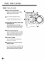 8
8
-
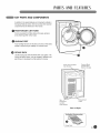 9
9
-
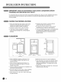 10
10
-
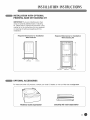 11
11
-
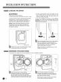 12
12
-
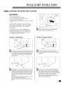 13
13
-
 14
14
-
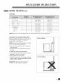 15
15
-
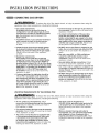 16
16
-
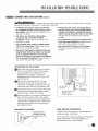 17
17
-
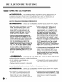 18
18
-
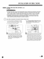 19
19
-
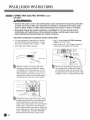 20
20
-
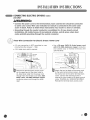 21
21
-
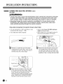 22
22
-
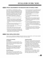 23
23
-
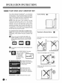 24
24
-
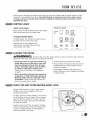 25
25
-
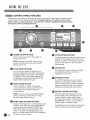 26
26
-
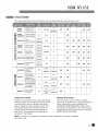 27
27
-
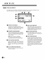 28
28
-
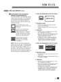 29
29
-
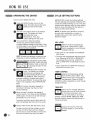 30
30
-
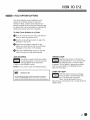 31
31
-
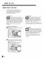 32
32
-
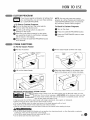 33
33
-
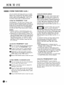 34
34
-
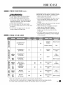 35
35
-
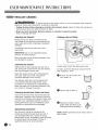 36
36
-
 37
37
-
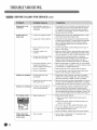 38
38
-
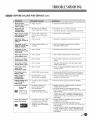 39
39
-
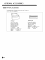 40
40
-
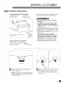 41
41
-
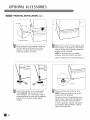 42
42
-
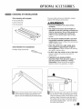 43
43
-
 44
44
-
 45
45
-
 46
46
-
 47
47
-
 48
48
-
 49
49
-
 50
50
-
 51
51
-
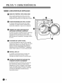 52
52
-
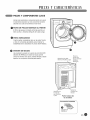 53
53
-
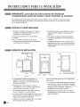 54
54
-
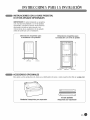 55
55
-
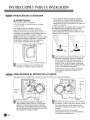 56
56
-
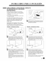 57
57
-
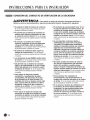 58
58
-
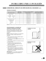 59
59
-
 60
60
-
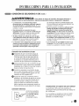 61
61
-
 62
62
-
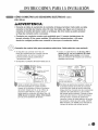 63
63
-
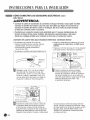 64
64
-
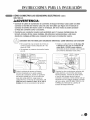 65
65
-
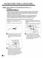 66
66
-
 67
67
-
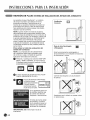 68
68
-
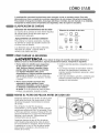 69
69
-
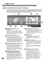 70
70
-
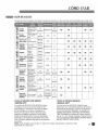 71
71
-
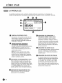 72
72
-
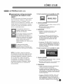 73
73
-
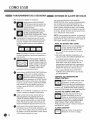 74
74
-
 75
75
-
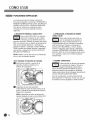 76
76
-
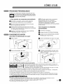 77
77
-
 78
78
-
 79
79
-
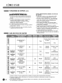 80
80
-
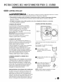 81
81
-
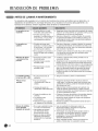 82
82
-
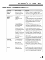 83
83
-
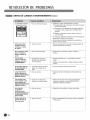 84
84
-
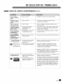 85
85
-
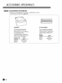 86
86
-
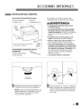 87
87
-
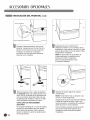 88
88
-
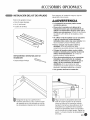 89
89
-
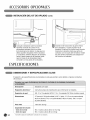 90
90
-
 91
91


en otros idiomas
- English: LG DLEX3001P Owner's manual
Artículos relacionados
-
LG DLGX2802W El manual del propietario
-
LG DLGX8388NM El manual del propietario
-
-
LG DLG1320W El manual del propietario
-
-
-
LG DLGX7188RM El manual del propietario
-
LG DLE2301W El manual del propietario
-
-
LG DLEX2501V El manual del propietario