
6.0 Horse Power
YARD VACUUM
Sears, Roebuck and Co., Hoffman Estates, IL 60179, U.S.A.
Printed in U.S.A.
Operator’s Manual
ES
•Safety
• Assembly
• Operation
• Maintenance
•Parts
• Español, p. 39
Visit our Sears website: www.sears.com/craftsman
Model No. 247.770550
CAUTION: Before using
this product, read this
manual and follow all
Safety Rules and
Operating Instructions.
FORM NO.
769-00407D.fm
(8/4/2004)

2
WARRANTY
TABLE OF CONTENTS
Content Page
Warranty 2
Safety 3
Assembly 6
Operation 9
Maintenance 13
Content Page
Service and Adjustments 15
Storage 17
Troubleshooting 18
Parts List 19
Español 39
Model Number.........................................................
Serial Number...........................................................
Date of Purchase......................................................
Record both serial number and date of purchase and
keep in a safe place for future reference.
PRODUCT SPECIFICATION
One Year Full Warranty on Craftsman Yard Vacuum
This equipment is covered by a one-year warranty, provided that it is maintained, lubricated, and tuned up
according to the instructions in the operator’s manual. During the warranty year, if this equipment experiences any
failure due to defects in material or workmanship, RETURN IT TO YOUR NEAREST SEARS PARTS & REPAIR
CENTER, and Sears will repair it, free of charge. In-home warranty service is available, but you will have to pay a
trip charge.
This Warranty does not cover:
• Expendable items which become worn during normal use, such as spark plugs, air cleaners, belts, and oil
filters.
• Tire replacement or repair caused by punctures from outside objects, such as nails, thorns, stumps, or glass.
• Repairs necessary because of operator abuse, including but not limited to, damage caused by objects, such
as stones, metal debris or oversized pieces of wood, or impacting objects that bend the frame or crankshaft,
or over-speeding the engine.
• Repairs necessary because of operator negligence, including but not limited to, electrical and mechanical
damage caused by improper storage, failure to use the proper grade and amount of engine oil, or failure to
maintain the equipment according to the instructions contained in the operator’s manual.
• Engine (fuel system) cleaning or repairs caused by fuel determine to be contaminated or oxidized (stale). In
general, fuel should be used within 30 days of its purchase date.
• Equipment if used for commercial or rental purposes.
TO LOCATE THE NEAREST SEARS PARTS & REPAIR CENTER OR TO SCHEDULE SERVICE, SIMPLY
CONTACT SEARS AT 1-800-4-MY-HOME®.
This warranty gives you specific legal rights and you may also have other rights, which vary from state to state.
Sears, Roebuck and Co., Dept. 817WA, Hoffman Estates, IL 60179
Horsepower: 6.0 Horse Power
Engine Oil Type SAE 30
Engine Oil Capacity 18 Ounces
Fuel Capacity: 1 1/2 Quarts
Spark Plug Champion RJ-19LM
Spark Plug Gap .030"
247.770550

3
WARNING: This symbol points out important safety instructions which, if not followed, could
endanger the personal safety and/or property of yourself and others. Read and follow all
instructions in this manual before attempting to operate this machine. Failure to comply with these
instructions may result in personal injury. When you see this symbol - heed its warning.
WARNING: Engine Exhaust, some of its constituents, and certain vehicle
components contain or emit chemicals known to State of California to cause cancer
and birth defects or other reproductive harm.
DANGER: This machine was built to be operated according to the rules for safe operation in this
manual. As with any type of power equipment, carelessness or error on the part of the operator can
result in serious injury. This machine is capable of amputating hands and feet and throwing objects.
Failure to observe the following safety instructions could result in serious injury or death.
TRAINING
1. Read, understand, and follow all instructions on
the machine and in the manual(s) before
attempting to assemble and operate. Keep this
manual in a safe place for future and regular
reference and for ordering replacement parts.
2. Be familiar with all controls and their proper
operation. Know how to stop the machine and
disengage them quickly.
3. Never allow children under 16 years old to
operate this machine. Children 16 years old and
over should read and understand the operation
instructions and safety rules in this manual and
should be trained and supervised by a parent.
4. Never allow adults to operate this machine
without proper instruction.
5. Keep bystanders, helpers, pets, and children at
least 75 feet from the machine while it is in
operation. Stop machine if anyone enters the
area.
6. Never run an engine indoors or in a poorly
ventilated area. Engine exhaust contains carbon
monoxide, an odorless and deadly gas.
7. Do not put hands and feet near rotating parts or in
the feeding chambers and discharge opening.
Contact with the rotating impeller can amputate
fingers, hands, and feet.
8. Never attempt to unclog either the feed intake or
discharge opening, remove or empty vacuum
bag, or inspect and repair the machine while the
engine is running. Shut the engine off and wait
until all moving parts have come to a complete
stop. Disconnect the spark plug wire and ground
it against the engine.
PREPARATION
1. Thoroughly inspect the area where the
equipment is to be used. Remove all rocks,
bottles, cans, or other foreign objects which could
be picked up or thrown and cause personal injury
or damage to the machine.
2. Always wear safety glasses or safety goggles
during operation or while performing an
adjustment or repair, to protect eyes. Thrown
objects which ricochet can cause serious injury to
the eyes.
3. Wear sturdy, rough-soled work shoes and close-
fitting slacks and shirts. Loose fitting clothes or
jewelry can be caught in movable parts. Never
operate this machine in bare feet or sandals.
Wear leather work gloves when feeding material
in the chipper chute.
4. Before starting, check all bolts and screws for
proper tightness to be sure the machine is in safe
working condition. Also, visually inspect machine
for any damage at frequent intervals.
5. Maintain or replace safety and instructions labels,
as necessary.
6. To avoid personal injury or property damage use
extreme care in handling gasoline. Gasoline is
extremely flammable and the vapors are
explosive. Serious personal injury can occur
when gasoline is spilled on yourself or your
clothes which can ignite. Wash your skin and
change clothes immediately.
a. Use only an approved gasoline container.
b. Extinguish all cigarettes, cigars, pipes, and
other sources of ignition.
c. Never fuel machine indoors.
d. Never remove gas cap or add while the
engine is hot or running.
e. Allow engine to cool at least two minutes
before refueling.
f. Never over fill fuel tank. Fill tank to no more
than 1/2 inch below bottom of filler neck to
provide space for fuel expansion.
g. Replace gasoline cap and tighten securely.
h. If gasoline is spilled, wipe it off the engine
and equipment. Move machine to another
area. Wait 5 minutes before starting the
engine.
SAFETY

4
i. Never store the machine or fuel container
inside where there is an open flame, spark,
or pilot light (e.g. furnace, water heater,
space heater, clothes dryer, etc.)
j. To reduce a fire hazard, keep machine free
of grass, leaves, or other debris build-up.
Clean up oil fuel spillage and remove any fuel
soaked debris.
k. Allow machine to cool at least 5 minutes
before storing.
OPERATION
1. Do not put hands and feet near rotating parts or in
the feeding chambers and discharge opening.
Contact with the rotating impeller can amputate
fingers, hands, and feet.
2. Before starting the machine, make sure the chipper
chute, feed intake, and cutting chamber are empty
and free of all debris.
3. Thoroughly inspect all material to be shredded and
remove any metal, rocks, bottles, cans, or other
foreign objects which could cause personal injury
or damage to the machine.
4. If the impeller strikes a foreign object or if your
machine should start making an unusual noise or
vibration, immediately shut the engine off. Allow the
impeller to come to a complete stop. Disconnect
the spark plug wire, ground it against the engine
and perform the following steps:
a. Inspect for damage.
b. Repair or replace any damaged parts.
c. Check for any loose parts and tighten to
assure continued safe operation.
5. Do not allow an accumulation of processed
material to build up in the discharge area. This can
prevent proper discharge and result in kickback of
material through the feed opening.
6. Do not attempt to shred or chip material larger than
specified on the machine or in this manual.
Personal injury or machine damage could result.
7. Never attempt to unclog either the feed intake or
discharge opening while the engine is running.
Shut the engine off, wait until all moving parts have
stopped, disconnect the spark plug wire and
ground it against the engine before clearing debris.
8. Never operate without vacuum bag and discharge
chute properly attached to the machine. Never
empty or change vacuum bag while the engine is
running. Rear end of vacuum bag must be kept
closed at all times during operation.
9. Never operate without either the inlet nozzle or
optional hose attachment properly attached to the
machine. Never attempt to attach or change either
attachment while the engine is running.
10. Keep all guards, deflectors and safety devices in
place and operating properly.
11. Keep your face and body back and to the side of
the chipper chute while feeding material into the
machine to avoid accidental kickback injuries.
12. Never operate this machine without good visibility
or light. Always be sure of your footing and keep a
firm hold on the handles.
13. Do not operate this machine on a gravel surface.
14. Do not operate this machine while under the
influence of alcohol or drugs.
15. Muffler and engine become hot and can cause a
burn. Do not touch.
16. Never pick up or carry machine while the engine is
running.
MAINTENANCE AND STORAGE
1. Never tamper with safety devices. Check their
proper operation regularly.
2. Check bolts and screws for proper tightness at
frequent intervals to keep the machine in safe
working condition. Also, visually inspect machine
for any damage and repair, if needed.
3. Before cleaning, repairing, or inspecting, stop the
engine and make certain the impeller and all
moving parts have stopped. Disconnect the spark
plug wire and ground it against the engine to
prevent unintended starting.
4. Do not change the engine governor settings or
overspeed the engine. The governor controls the
maximum safe operating speed of the engine.
5. Maintain or replace safety and instruction labels, as
necessary.
6. Follow this manual for safe loading, unloading,
transporting, and storage of this machine.
7. Never store the machine or fuel container inside
where there is an open flame, spark or pilot light
such as a water heater, furnace, clothes dryer, etc.
8. Always refer to the operator’s manual for proper
instructions on off-season storage.
9. If the fuel tank has to be drained, do this outdoors.
10. Observe proper disposal laws and regulations for
gas, oil, etc. to protect the environment.

5
Look For Relevant Emissions Durability Period and
Air Index Information On Your Engine Emissions Label
Engines that are certified to meet the California Air Resources Board (CARB)Tier 2 Emission Standards must display
information regarding the Emissions Durability Period and the Air Index. Sears, Roebuck and Co., U.S.A. makes this
information available to the consumer on our emission labels.
The Emissions Durability Period describes the number of hours of actual running time for which the engine is certified to be
emissions compliant, assuming proper maintenance in accordance with the Operating & Maintenance Instructions. The
following categories are used:
Moderate: Engine is certified to be emission compliant for 125 hours of actual engine running time.
Intermediate: Engine is certified to be emission compliant for 250 hours of actual engine running time.
Extended: Engine is certified to be emission compliant for 500 hours of actual engine running time.
For example, a typical walk-behind lawn mower is used 20 to 25 hours per year. Therefore, the Emissions Durability Period
of an engine with an intermediate rating would equate to 10 to 12 years.
The Air Index is a calculated number describing the relative level of emissions for a specific engine family. The lower the Air
Index, the cleaner the engine. This information is displayed in graphical form on the emissions label.
After July 1, 2000, Look For Emissions Compliance Period On
Engine Emissions Compliance Label
After July 1, 2000 certain Sears, Roebuck and Co., U.S.A. engines will be certified to meet the United States Environmental
Protection Agency (USEPA) Phase 2 emission standards. For Phase 2 certified engines, the Emissions Compliance Period
referred to on the Emissions Compliance label indicates the number of operating hours for which the engine has been shown
to meet Federal emission requirements. For engines less than 225 cc displacement, Category C = 125 hours, B = 250 hours
and A = 500 hours. For engines of 225 cc or more, Category C = 250 hours, B = 500 hours and A = 1000 hours.
The displacement engines of Model Series 210000 is 344 cc, 280000 is 465 cc, 310000 engines is 501 cc.
This is a generic representation of the
emission label typically found on a
certified engine.
Congratulations on making a smart purchase.Your new
Craftsman® product is designed and manufactured for years of
dependable operation. But like all products, it may require repair
from time to time. That’s when having a Repair Protection
Agreement can save you money and aggravation.
Here’s what’s included in the Agreement:
Expert service by our 12,000 professional repair
specialists
Unlimited service and no charge for parts and labor
on all covered repairs
Product replacement if your covered product can’t be
fixed
Discount of 10% from regular price of service and
service-related parts not covered by the agreement;
also, 10% off regular price of preventive maintenance
check
Fast help by phone - phone support from a Sears
technician on products requiring in-home repair, plus
convenient repair scheduling
Once you purchase the Agreement, a simple phone call is all
that it takes for you to schedule service. You can call anytime
day or night, or schedule a service appointment online.
Sears has over 12,000 professional repair specialists, who have
access to over 4.5 million quality parts and accessories. That’s
the kind of professionalism you can count on to help prolong the
life of your new purchase for years to come. Purchase your
Repair Protection Agreement today!
Some limitations and exclusions apply. For prices and
additional information call 1-800-827-6655.
Sears Installation Service
For Sears professional installation of home appliances, garage
door openers, water heaters, and other major home items, in the
U.S.A. call 1-800-4-MY-HOME®
REPAIR PROTECTION AGREEMENT

6
Figure 1
IMPORTANT: This unit is shipped without gasoline or
oil in the engine. After assembly, see OPERATION
section of this manual for proper fuel and engine oil
fill-up.
NOTE: Reference to right and left hand side of the
Yard Vacuum is observed from the operating
position.
This Yard Vacuum has been completely assembled
at the factory, except for the handle, bag, and blower
chute. These parts are shipped loose in the carton.
A pair of safety glasses, a bottle of engine oil, and
the operator’s manual are also included in the car-
ton. See Figure 1.
OPENING CARTON
• Cut each corner of the carton vertically from top
to bottom.
• Remove all loose parts.
• Remove loose packing material.
REMOVING UNIT FROM CARTON
• Lift unit from the rear to detach it from underlying
carton material and roll unit out of carton.
• Check carton thoroughly for any other loose
parts.
NOTE: Make sure not to crimp cables while
removing loose parts or the entire unit from the
carton.
LOOSE PARTS IN CARTON (See Figure 1)
• Upper and Lower Handle
• Hose Assembly
•Bag
• Blower Chute
• Safety Glasses
• A Bottle of Engine Oil (may be located in bag)
• Operator’s Manual
DISCONNECTING SPARK PLUG
Before proceeding with assembly of your new Yard
Vacuum, disconnect the spark plug wire from the
spark plug and ground onto the retaining post on the
engine. This will prevent accidental starting of the
engine. See Figure 2.
Figure 2
Blower Chute
Upper
Handle
Lower
Handle
Rope
Guide
Handle
Knobs
Operator’s
Manual
Lower
Hose
Handle
Bracket
Carriage
Screw
Wing
Nuts
Wing
Nut
Upper
Hose
Handle
Bracket
Hose
Assembly
Bag
Bottle of
Engine Oil
Safety Glasses
Spark
Plug Wire
Retaining Post
Disconnect and Ground to Post
ASSEMBLY

7
ATTACHING THE HANDLE
• Remove the hairpin clips from the handle
brackets and remove the carriage screws and
wing nuts from the lower handle. See Figure 3A.
Figure 3
• Place the bottom holes in lower handle over the
pins on the handle brackets and secure with
hairpin clips.
• Insert carriage screws through upper hole in
lower handle from the inside and secure with
wing nuts.
• Unfold the upper handle until it aligns with lower
handle. Make sure the rope guide is on the right
side of upper handle. See Figure 3B.
IMPORTANT: Make sure the cables are routed outside
the lower handle. Also, do not crimp the cables while
lifting up the handles.
• Secure the two handles by tightening the handle
knobs (carriage bolts must be seated properly
into the handle). See Figure 3B.
• Pull the two cable ties attached to the cables tight
approximately 8 inches from each cable end and
place the cables into the cable guide. See Figure
3A and B.
• Loosen the wing nut that secures the rope guide
to the right side of upper handle.
• Pull the starter rope out of the engine slowly and
slip the starter rope into the rope guide. Tighten
the wing nut. See Figure 5A.
B
A
Wing Nuts
Carriage Bolt
Hairpin Clip
Handle
Bracket
Rope
Guide
Handle
Knobs
Lower
Handle
Carriage
Bolts
Wing
Nut
Attaching The Hose Assembly
• Slide hose adapter of hose assembly into the
base adapter located on the left front of the Yard
Vacuum. See Figure 4.
Figure 4
• Pull spring loaded pin out on the base and align
pin with the first hole (closest to the end of the
tube) in the hose adapter.
• Release the pin to lock the hose in place.
• Snap the hose handle first into the upper hose
handle bracket and then into the lower hose
handle bracket. Refer to Figure 5A.
Figure 5
• Lay hose tubing on hanger bracket next to
chipper chute. Refer to Figure 5B.
Spring
Loaded Pin
Hose
Adapter
Upper
Hose
Lower
Hose
Handle
Hose
Handle
A
B
Hanger
Bracket
Hose
Starter
Rope
Rope
Guide
Bracket
Handle
Bracket
Chipper
Chute

8
ATTACHING THE BAG
• Grasp bag handle with one hand and slide locking
rod on mounting bracket with other hand toward
engine. Use the end of mounting bracket as
leverage when sliding the locking rod. See Figure 6.
Figure 6
• Slip bag over the rim of the discharge opening and
release locking rod to secure bag in place.
• Snap bag clip to the top of the lower handle.
• Place the lower straps on the bag over the top of
lower handle, hooking them on the studs.
NOTE: The bag/chute switch button attached to the
mounting bracket must be fully depressed by the tip of
front tab on bag handle when securing the bag or
engine will not start.
ATTACHING THE BLOWER CHUTE
NOTE: The bag must be removed before installing the
blower chute.
• Grasp blower chute with one hand and slide lock-
ing rod on mounting bracket with other hand
toward engine. Use the end of mounting bracket
as leverage when sliding the locking rod.
See Figure 7.
• Slip blower chute over rim of discharge opening
and release locking rod to secure chute in place.
• Raise the nozzle height to the highest setting
when using the blower chute. Refer to nozzle
height adjustment in the ADJUSTMENT section
on page 15.
NOTE: The bag/chute switch button attached to the
mounting bracket must be fully depressed by the tip of
front tab on the blower chute or engine will not start.
Figure 7
Bag Handle
Straps
Stud
Front Tab
Stud
Locking Rod
Front
Tab
Locking
Rod
Locking
Rod
Blower
Chute
Front
Tab
Bag/Chute
Switch
Button

9
Know Your Yard Vacuum
Read this operator’s manual and safety rules before operating your Yard Vacuum. Compare the illustrations
below with your equipment to familiarize yourself with the location of various controls and adjustments. Save
this manual for future reference.
The operation of any Yard Vacuum can result in foreign objects being thrown into the eyes,
which can result in severe eye damage. Always wear safety glasses, provided with the
Yard Vacuum, for operating this equipment or while performing any adjustments or repairs on
it.
OPERATING CONTROLS (See Figure 8)
Chipper Chute
Allows twigs and small branches up to 1 1/2" in
diameter to be fed into the impeller for chipping.
Nozzle
Yard waste such as leaves and pine needles can be
vacuumed up through the nozzle for shredding.
Bag
Collects shredded material fed in through the chipper
chute or vacuumed in through the nozzle.
Blower Chute
When attached to unit, the blower chute is used to
blow or scatter yard waste such as leaves, pine
needle, or small twigs across yard.
Bag Handle
Used to grasp bag in order to assist in attaching,
removing, and emptying bag.
Nozzle Height Adjustment Lever
Used to adjust the nozzle ground clearance ranging
from 5/8" to 4 1/8".
Throttle Control
This lever controls the engine speed and stop
function. Through three separate positions on the
lever from left to right, the operation is as follows:
Choke Control
The choke control is used to choke of the carburetor
and assist in starting the engine.
Starter Handle
Used to start the engine.
WEAR YOUR
FORESIGHT IS BETTER
THAN NO SIGHT
SAFETY GLASSES
Figure 8
Nozzle
Starter
Bag Handle
Bag
Chipper
Chute
Nozzle Height
Spark Plug Wire
Choke Control
Meets ANSI safety standards
Craftsman Yard Vacuums conform to the safety standard of the American National Standards Institute (ANSI).
Throttle Control
Adjustment Lever
Blower Chute
Stop
Engine
Off
Slow/
Start/
OPERATION
Handle
Idle
Run
Lower Hose Handle
Hose Handle
Nozzle/Hose
Vac Lever
Hanger
Bracket
Hose
Assembly
Bracket

10
Hose Assembly
Used as an alternative to the nozzle to vacuum yard
waste such as leaves or pine needles in hard to
reach places.
Hose Handle
Used to guide hose assembly when vacuuming.
Nozzle/Hose Vac Lever
The nozzle/hose vac handle is located on top of the
nozzle. Use it to switch vacuum suction between the
nozzle and the hose assembly.
GAS AND OIL FILL-UP
Oil (one bottle shipped with unit)
First Time Use
• Remove oil fill dipstick.
• With the Yard Vacuum on level ground, use a
funnel to empty entire contents of oil bottle
provided into the engine.
• Replace oil fill dipstick and tighten.
Subsequent Uses
Only use high quality detergent oil rated with API
service classification SF, SG, or SH. Select the oil’s
SAE viscosity grade according to the expected
operating temperature. Follow the chart below.
Although multi-viscosity oils (5W30, 10W30, etc.)
improve starting in cold weather, they will result in
increased oil consumption when used above 32°F.
Check your engine oil level more frequently to avoid
possible engine damage from running low on oil.
• Check the oil level making certain not to rub the
dipstick along the inside walls of the oil fill tube.
This would result in a false dipstick reading. Refill
to FULL mark on dipstick, if necessary. Capacity
is approximately 18 oz. Overfilling will cause the
engine to smoke profusely and will result in poor
engine performance.
• Replace oil fill dipstick and tighten.
• Keep oil level at FULL. Running the engine with
too little oil can result in permanent engine
damage.
Gasoline
• Remove fuel cap from the fuel tank.
• Make sure the container from which you will pour
the gasoline is clean and free from rust or foreign
particles. Never use gasoline that may be stale
from long periods of storage in its container.
Gasoline that has been sitting for any period
Warmer
Colder
32
°F
5W30 SAE 30
Oil Viscosity Chart
longer than four weeks should be considered
stale.
• Fill fuel tank with clean, fresh, unleaded regular
gasoline only. Do not use gasoline containing
METHANOL. Replace fuel cap.
• To avoid engine problems, the fuel system should
be emptied before storage for 30 days or longer.
Drain the fuel from the tank by running the engine
until the fuel tank is empty. Use fresh fuel next
season. See STORAGE section for additional
information.
WARNING: Use extreme care when
handling gasoline. Gasoline is extremely
flammable and the vapors are explosive.
Never fuel machine indoors or while the
engine is hot or running. Extinguish
cigarettes, cigars, pipes, and other
sources of ignition.
• Check the fuel level periodically to avoid running
out of gasoline while operating the Yard Vacuum.
If the unit runs out of gas as it is chipping, it may
be necessary to unclog the discharge area before
it can be restarted. Refer to SERVICE AND
ADJUSTMENT section on page 15.
TO STOP ENGINE
• Move throttle control lever to STOP or OFF
position.
• Disconnect spark plug wire and ground it to the
post to prevent accidental starting while the
equipment is unattended.
WARNING: When moving throttle control
lever, be careful of heated surfaces and
sharp edges on muffler guard.
TO START ENGINE
1. Attach spark plug wire and rubber boot to spark
plug.
2. The bag/chute switch button must be fully
depressed by the tip of front tab on bag handle
or blower chute for engine to start.
3. Make sure bag/chute switch wire is connected to
engine and grounded to mounting bracket.
4. Gas tank should be filled 3/4 to full before start-
ing.
5. Move throttle control to START/RUN (Rabbit)
position. See Figure 9.
6. Move the choke control toward the throttle
control to choke the engine’s carburetor. (A
warm engine may not require choking.) See
Figure 9.

11
Figure 9
7. Standing behind the unit, grasp starter handle
and pull rope out until you feel a drag.
8. Pull the rope with a rapid, continuous, full arm
stroke. Keep a firm grip on the starter handle.
Let the rope rewind slowly.
9. Repeat, if necessary, until engine starts. When
engine starts, move choke control gradually
away from the throttle control.
10. If engine falters, move choke control back
toward the throttle control and repeat steps 7-9.
11. ALWAYS keep the throttle control in the START/
RUN position when operating the Yard Vacuum.
TO EMPTY BAG
• Unhook bag straps from the lower handle and
unsnap bag clip from top of the lower handle. See
Figure 10.
• Grasp bag handle with one hand and pull lock rod
on mounting bracket with other hand toward
engine to release.
• Lift bag off back of unit. Refer to .
• Twist the two buttons on the back of the bag to
unlock and empty contents. See Figure 10.
• Hold bag handle and bag clip while emptying the
contents.
• Compress bag opening and fold inner flap over
opening.
• Fold outer flap over inner flap and insert buttons
on the bag through metal outlets.
• Twist the buttons to lock bag.
Figure 10
TO REMOVE BLOWER CHUTE
• Grasp blower chute with one hand and pull lock
rod on mounting bracket with other hand toward
engine to release. Refer to Figure 7.
• Remove blower chute from over the rim of the
discharge opening.
Using the Nozzle Vacuum
Place nozzle/hose vac handle in the top position on
the nozzle to vacuum through nozzle. See Figure 11.
Figure 11
Choke Control
Throttle Control
Buttons
Inner Flap
Outer Flap
Bag Handle
Strap
Bag
Clip
Nozzle/Hose
Vac Lever
Spring Loaded Pin
(First Hole)
(Top Position)
Nozzle
Hose
Adapter

12
• The spring loaded pin must be in the first hole
(closest to the end of the tube) of the hose adapter
to operate the nozzle vac.
• Place both hands on top of upper handle to push
unit over yard waste.
Yard waste such as leaves and pine needles can be
vacuumed up through the nozzle for shredding. After
material has been shredded by the flail blades on the
impeller assembly, it will be discharged into catcher bag
or through blower chute. Do not attempt to shred or chip
any material other than vegetation found in a normal
yard (i.e. branches, leaves, twigs, etc.) Avoid fibrous
plants such as tomato vines until they are thoroughly
dried out. Materials such as stalks or heavy branches
up to 1 1/2” in diameter may be fed into the chipper
chute.
WARNING: Do not attempt to shred, chip,
or vacuum any material larger than
specified on the machine or in this
manual. Personal injury or damage to the
machine could result.
IMPORTANT: The flail screen is located inside the
housing in the discharge area. If the flail screen
becomes clogged, remove and clean as instructed in
“Service and ADJUSTMENTS” on page 15 . For best
performance, it is also important to keep the chipper
blade sharp.
WARNING: Do not at any time make any
adjustments without first stopping engine
and disconnecting spark plug wire.
Using the Hose Assembly
• Place nozzle/hose vac handle in the bottom
position on the nozzle to redirect vacuum to the
hose assembly. See Figure 12.
• The spring loaded pin must be in the second hole of
the hose adapter to operate the hose assembly.
• Unhook the hose from upper and lower hose
handle brackets and grasp the hose handle to
guide the hose while vacuuming yard waste such
as leaves or pine needles in hard to reach places.
Figure 12
Nozzle Height Adjustment
The nozzle can be adjusted to any six positions,
ranging from 5/8” to 4 1/8” ground clearance. The
nozzle height has to be adjusted according to yard
conditions. Move the height adjustment levers forward
or backward to adjust the nozzle upwards or
downwards. See Figure 13.
NOTE: In general, raise the nozzle height to vacuum
a thick layer of leaves or to operate with the blower
chute. Lower the nozzle height for smoother surfaces.
Figure 13
Nozzle/Hose
Vac Handle
Spring Loaded Pin
(Second Hole)
(Bottom Position)
Nozzle
Nozzle Height
Adjustment
Lever

13
GENERAL RECOMMENDATIONS
• Always observe safety rules when performing any
maintenance.
• The warranty on this Yard Vacuum does not
cover items that have been subjected to operator
abuse or negligence. To receive full value from
the warranty, operator must maintain the
equipment as instructed in this manual.
• Some adjustments will need to be made
periodically to maintain your equipment properly.
• Follow the maintenance schedule.
• Periodically check all fasteners and make sure
they are tight.
WARNING: Always stop the engine and
disconnect and ground the spark plug
wire before performing any maintenance
or adjustments.
LUBRICATION
• Wheels- Place a few drops of SAE 30 oil on each
shoulder screw once a season. Refer to Figure 19
on page 16.
• Nozzle height adjustment levers- Lubricate
nozzle height adjustment levers with light oil.
Refer to Figure 8.
• Locking Rod- Lubricate the lock rod and
compression springs which attach to the
mounting bracket. Refer to Figure 7.
CLEAN EQUIPMENT
• Clean the Yard Vacuum thoroughly after each
use.
• Wash the bag periodically with water. Allow to
dry thoroughly in the shade.
• If the flail screen becomes clogged, remove and
clean as instructed in the SERVICE AND
ADJUSTMENT section.
NOTE: Cleaning with a forceful spray of water is not
recommended as it could contaminate the fuel
system.
CHECK ENGINE OIL
• Stop engine and wait several minutes before
checking oil level. With engine on level ground,
the oil must be to FULL mark on dipstick.
• Remove oil fill dipstick.
• Check oil level on dipstick. Level should be at
FULL mark. (If not, see “Subsequent Uses” on
page 10).
• Replace oil fill dipstick and tighten.
CHANGE ENGINE OIL
• Only use high quality detergent oil rated with API
service classification SF, SG, or SH. Select the
oil’s SAE viscosity grade according to the
expected operating temperature. Refer to
operation section for viscosity chart.
MAINTENANCE
Maintenance Schedule
Maint. Tasks
Before
each use
After
each use
After first
5 hours
operation
Every 25
hours
operation
Every 50
hours
operation
Once a
season
Before
storage
Service Dates
Product:
Lubrication
Clean Equipment
Engine:
Check engine oil
Change engine oil
Service Air Cleaner
Service spark plug
Service Muffler
Clean Engine

14
• Change engine oil after the first five hours of
operation, and every twenty-five hours thereafter.
TO DRAIN OIL
Drain oil while engine is warm. Follow the instructions
given below.
• Drain the fuel from the tank by running the engine
until the fuel tank is empty.
• Remove oil fill dipstick.
• Tip unit on its side to drain through the oil fill tube.
• When engine is drained of all oil, refill with
approximately 18 oz. of fresh oil. Refer to Gas
And Oil Fill-up in OPERATION section.
• Replace oil fill dipstick and tighten.
SERVICE AIR CLEANER
The air cleaner prevents damaging dirt, dust, etc.,
from entering the carburetor and being forced into the
engine and is important to engine life and
performance. The air cleaner consists of a pleated
filter. Never run the engine without an air cleaner
completely assembled.
To Service Air Cleaner:
• Loosen screw and tilt plastic housing cover on
side of engine down. See Figure 14.
• Remove pleated filter from plastic housing cover
and replace with clean or new filter.
• Tilt cover up into place and tighten screw.
Figure 14
NOTE: If the filter is torn or damaged in any way,
replace it.
WARNING: Temperature of muffler and
nearby areas may exceed 150
o
F (65
o
C).
Avoid these areas.
Air Cleaner
Housing
SERVICE SPARK PLUG
• Clean the spark plug and reset the gap to.030" at
least once a season or every 50 hours of
operation. See Figure 15. Spark plug
replacement is recommended at the start of each
season. Refer to engine parts list for correct
spark plug type.
NOTE: Do not sandblast spark plug. Spark plug
should be cleaned by scraping or wire brushing and
washing with a commercial solvent.
Figure 15
SERVICE MUFFLER
• Inspect muffler periodically, and replace if
necessary.
• If your engine is equipped with a spark arrester
screen assembly, remove after every 50 hours of
use for cleaning and inspection. Replace if
damaged.
WARNING: Do not operate the Yard
Vacuum without a muffler or tamper with
the exhaust system. Damaged mufflers
or spark arresters could create a fire
hazard.
CLEAN ENGINE
• Clean engine by removing dirt and debris with a
cloth or brush.
• Frequently remove grass clippings, dirt, and
debris from cooling fins, air intake screen, levers,
and linkage. This will help ensure adequate
cooling and engine speed.
Spark Plug
.030" Gap Gauge

15
WARNING: Do not at any time make any
adjustment to the unit without first
stopping engine and disconnecting
spark plug wire.
Nozzle Height Adjustment
The nozzle can be adjusted to any six positions,
ranging from 5/8” to 4 1/8” ground clearance. The
nozzle height has to be adjusted according to yard
conditions. Move the height adjustment levers
forward or backward to adjust the nozzle upwards or
downwards. See Figure 16.
NOTE: In general, raise the nozzle height to
vacuum a thick layer of leaves or to operate with the
blower chute. Lower the nozzle height for smoother
surfaces.
Figure 16
CARBURETOR ADJUSTMENT
WARNING: If any adjustments (e.g.
carburetor) are made to the engine
while the engine is running, keep clear
of all moving parts. Be careful of heated
surfaces and muffler.
The carburetor has been pre-set at the factory and
should not require adjustment. If your engine does
not operate properly due to suspected carburetor
problems, take your Yard Vacuum to a Sears Parts &
Repair Center for repair and adjustment.
ENGINE SPEED
The engine speed on your Yard Vacuum has been
set at the factory. Do not attempt to increase the
engine RPM. If you think that the engine is running
too fast or too slow, take your Yard Vacuum to the
nearest Sears Parts & Repair Center for repair and
adjustment.
WARNING: Do not attempt to alter the
engine speed by tampering with the
engine’s governor linkage. Doing so
could result in serious personal injury
and damage to the engine. The engine
RPM has been set at the factory.
REMOVING THE FLAIL SCREEN
If the discharge area becomes clogged, remove the
flail screen and clean area as follows.
• Stop the engine. Make certain the chipper
shredder vacuum has come to a complete stop.
• Before unclogging the discharge chute,
disconnect and ground the spark plug wire to
retaining post..
• Remove the vacuum bag or blower chute from
the unit as instructed in the OPERATION section
to obtain access to flail screen. See Figure 17.
Figure 17
• Remove self-tapping screw on right side of unit
that attaches to the flail screen. See Figure 18.
Figure 18
• Remove hex screw on top of rear housing near
mounting bracket and the flange lock nut that
secures flail screen. See Figure 17.
• Remove and clean the screen by scraping or
washing with water. Reinstall the screen.
Nozzle
Nozzle Height
Adjustment
Lever
Flail Screen
Flange
Hex Screw
REAR VIEW
Lock Nut
Remove
Self-Tapping
Screw
SERVICE AND ADJUSTMENTS

16
SHARPENING OR REPLACING CHIPPER
BLADE
Because the engine on this unit has a tapered
crankshaft, a special impeller removal tool (part
number 753-0900) is required to remove the impeller
assembly. For further assistance, contact your Sears
Service Center.
NOTE: When tipping the unit, empty the fuel tank
and keep engine spark plug side up.
• Disconnect and ground the spark plug wire to
retaing post.
• Remove hose assembly and bag assembly.
• Remove the front hubcaps, flange lock nuts, front
wheels, and wave washers that attach to the pivot
arm assemblies. See Figure 19.
Figure 19
• Remove the shoulder screws, thrust washers,
and bell washers that go through the pivot arms
to the front support brace. The front support
brace and lock nut can be removed at this time as
well.
• Remove the three screws on the upper housing
that secure the nozzle cover and the nine screws
that secure the lower housing to the upper
housing. See Figure 20.
Figure 20
• Remove flange lock nut that secures flail screen
to the lower housing. The flail screen does not
have to be removed. Refer to Figure 17.
• Remove the hex bolt, lock washer, and flat
washer that secure the impeller assembly to the
crankshaft. See Figure 21.
Figure 21
• Apply lubricant to the threads of impeller removal
tool and then thread the tool into the crankshaft.
Stop when the impeller assembly can move on
the crankshaft.
• Remove the impeller assembly from the
crankshaft. Unthread the impeller removal tool
from the impeller assembly.
• Remove the chipper blade using a 3/16" allen
wrench on the outside of the blade and 1/2"
wrench on the underside of impeller assembly.
• Replace or sharpen chipper blade. The blade can
be sharpened with a file or on a grinding wheel.
• When sharpening blade, protect hands by using
gloves and follow the original angle of grind.
• Reassemble by performing the previous steps in
the opposite order and manner of removal.
• Tighten blade screws to 210 - 250 in-lbs.
• Tighten impeller bolt to 375 - 425 in-lbs.
NOTE: Make certain chipper blade is reassembled
with the sharp edge facing upward. See Figure 22.
Figure 22
Hubcap
Flange Lock Nut
Wave Washer
Shoulder
Screw
Bell Washer
Pivot Arm Assembly
Thrust Washer
Front Support
Brace & Lock Nut
Bell Washer
Height Adj. Bearing
Nozzle
Screws
Lower Housing
Screws
Housing
Screws
Upper
Housing
Impeller
Assembly
Hex Bolt
Lock Washer
Flat Washer
BOTTOM VIEW
Chipper
Blade
Flail
Blade
Flail
Blade
Chipper
Blade
Impeller
Assembly

17
STORAGE
Prepare your Craftsman Yard Vacuum for storage at
the end of the season or if the unit will not be used for
30 days or longer. A yearly check-up by your local
Sears Parts & Repair Center is a good way to ensure
that the unit runs properly next season.
Yard Vacuum
• Clean the equipment thoroughly.
• Wipe equipment with an oiled rag to prevent rust.
Use a light oil or silicone to wipe.
• Service the engine following instructions below.
• Store unit in a clean, dry area. Do not store next to
corrosive materials such as fertilizer.
Engine
IMPORTANT: It is important to prevent gum deposits
from forming in essential fuel system parts such as
the carburetor, fuel filter, fuel hose, or tank during
storage. Also, alcohol blended fuels (called gasohol or
using ethanol or methanol) can attract moisture which
leads to separation and formation of acids during
storage. Acidic gas can damage the fuel system of an
engine while in storage.
NOTE: Fuel stabilizer is an acceptable alternative to
emptying the tank of fuel in minimizing the formation
of fuel gum deposits during storage.
• Add stabilizer to gasoline in fuel tank or storage
container.
• Do not drain the gas tank and carburetor if using
fuel stabilizer.
In all cases, drain all the oil from the crankcase (this
should be done after the engine has been operated
and is still warm) and refill the crankcase with fresh
oil.
If you do not use a fuel stabilizer, follow these
instructions:
• Drain the fuel from the tank by running the
engine until the fuel tank is empty.
• Remove spark plug, pour approximately 1/2
ounce (approximately one tablespoon) of engine
oil into cylinder and crank slowly to distribute oil.
• Replace spark plug.
Other
• Do not store gasoline from one season to
another.
• Replace the gasoline can if it starts to rust. Rust
and/or dirt in the gasoline will cause problems.
• Store unit in a clean, dry area. Do not store next
to corrosive materials, such as fertilizer.
NOTE: If storing in an unventilated or metal storage
shed, be certain to rustproof the equipment by coat-
ing with a light oil or silicone.

18
NOTE: For repairs beyond the minor adjustments listed above, please contact your local Sears Parts & Repair
Center.
Problem Possible Cause(s) Corrective Action
Engine fails to start 1. Fuel tank empty or stale fuel.
2. Spark plug wire disconnected.
3. Cannot pull recoil cord.
4. Choke not in ON position.
5. Faulty spark plug.
6. Safety switch not depressed.
7. Safety switch wire is not
connected to engine or not
properly grounded.
1. Fill tank with clean, fresh gasoline. Fuel will not
last over thirty days unless a fuel stabilizer is
added.
2. Connect wire to spark plug.
3. Obstruction lodged in impeller. Disconnect
spark plug wire and remove lodged object.
4. Move CHOKE to ON position.
5. Clean, adjust gap or replace.
6. Safety switch must be depressed by the front
tab on the bag handle when securing the bag.
7. Connect safety switch wire to engine connector
and ground to mounting bracket.
Loss of power;
operation erratic
1. Spark plug wire loose.
2. Unit running on CHOKE.
3. Blocked fuel line or stale fuel.
4. Water or dirt in fuel system.
5. Carburetor out of adjustment.
6. Low engine RPM.
1. Connect and tighten spark plug wire.
2. Move choke lever to OFF position.
3. Disconnect fuel line at carburetor to drain fuel
tank; fill tank with clean fresh gasoline. Fuel will
not last over thirty days unless a fuel stabilizer is
used.
4. Disconnect fuel line at carburetor to drain fuel
tank. Refill with fresh fuel.
5. Contact your Sears Parts & Repair Center.
6. Always run engine at full throttle.
Too much vibration 1. Loose parts or damaged
impeller.
1. Stop engine immediately and disconnect spark
plug wire. Have unit serviced by a Sears Parts &
Repair Center.
Engine overheats 1. Carburetor not adjusted
2. Engine oil level low
1. Contact your Sears Parts & Repair Center.
2. Fill crankcase with proper selection of oil.
Unit does not
discharge
1. Discharge area clogged.
2. Foreign object lodged in
impeller.
3. Low engine RPM.
4. Vacuum bag is full.
1. Stop engine immediately and disconnect spark
plug wire. Clean flail screen and inside of
discharge opening. See Maintenance section of
this manual.
2. Stop engine immediately and disconnect spark
plug wire. Remove lodged object.
3. Always run engine at full throttle.
4. Empty bag.
Rate of discharge
slows considerably or
composition of
discharged material
changes
1. Low engine RPM.
2. Chipper blade dull.
1. Always run engine at full throttle.
2. Replace chipper blade or see your Sears Parts
& Repair Center.
TROUBLESHOOTING

19
Sears Craftsman 6.0 H.P. Yard Vacuum Model 247.770550
PARTS LIST
2
3
5
6
7
8
9
7
12
13
14
15
16
17
18
19
20
21
11
23
25
26
22
27
28
29
30
4
32
33
34
35
37
38
39
37
7
42
7
45
46
47
48
50
51
50
52
53
54
31
49
55
56
1
36
29

20
Sears Craftsman 6.0 H.P. Yard Vacuum Model 247.770550
Ref.
No.
Part No. Part Description
1. 736-0451 Saddle Washer,.320 x.93
2. 749-04172 Upper Handle
3. 720-0279 Knob
4. 710-0599 Screw, 1/4-20 x.500
5. 710-1205 Eye Bolt
6. 781-1056 Upper Handle Bracket
7. 710-0726 Hex Cap Screw 5/16-12 x.750
8. 720-0241 Handle Knob 5/16-18
9. 710-1174 Carriage Bolt
12. 731-04911 Nozzle Handle Clip
13. 749-04165 Lower Handle
14. 711-1293 Studs
15. 710-0703 Carriage Screw 1/4-20 x.75
16. 712-0397 Wing Nut 1/4-20
17. 751B699860 Shroud
18. 725-1700 Switch Cover
19. 725-3166 Safety Switch
20. 731-1613 Safety Switch Cover
21. 710-0224 Hex Washer Screw #10-16 x.50
22. 629-0920A Wire Harness
23. 714-0104 Cotter Pin
25. 732-0962 Compression Spring
26. 781-0778A Mounting Bracket
27. 747-1153 Lock Rod
28. 710-3195 Hex Cap Screw 5/16-18 x 4.5
29. 710-3025 Hex Cap Screw 5/16-18 x.625
30. 710-0502A Hex Washer Screw 3/8-16 x 1.25
31. 710-0751 Hex Cap Screw 1/4-20 x.620
32. 731-2484 Hose Base Adapter
33. 716-0104 E Ring.500 Dia
34. 732-3035 Compression Spring
35. 711-1571 Clevis Pin
36. 736-3020 Flat Washer.271 ID x.630 OD
37. 710-1220 Screw, #12-16 x.750
38. 710-0351 Screw #10 - 16 x.500
39. 781-04071 Upper Flail Housing
42. 681-0122 Chipper Chute Assembly
45. 781-1058 Hose Hanger Bracket
46. 712-04064 Flange Lock Nut, 1/4-20
47. 748-0457 Spacer
48. 731-2478 Hose Nozzle
49. 710-3288 Hex Cap Screw 1/4-20 x 2.625
50. 723-0295 Adjustment Clamp
51. 749-1270 Nozzle Handle
52. 764-0648 Vacuum Hose
53. 07071 Handle Grip
54. 731-2292 Hose Adapter
55. 736-0607 External L-Washer 5/16
56. 726-0139 Speed Nut
Ref.
No.
Part No. Part Description
NOTE: For painted parts, please refer to the list of color codes below. Please add the applicable color code, wherever needed,
to the part number to order a replacement part. For instance, if a part, numbered 700-xxxx, is painted Sears Red, the part num-
ber to order would be 700-xxxx-0721.
Sears Red: 0721
Oyster Grey: 0662
Powder Black: 0637

21
Sears Craftsman 6.0 H.P. Yard Vacuum Model 247.770550
1
2
3
4
5
6
8
9
62
63
64
13
14
15
19
20
21
22
23
24
27
28
29
30
31
33
35
36
37
38
61
40
53
42
43
44
58
59
60
47
48
49
50
51
52
42
53
55
44
11
10
12
55
7
16
13
15
57
55

22
Sears Craftsman 6.0 H.P. Yard Vacuum Model 247.770550
Ref.
No.
Part No. Part Description
1. 664-0094 Bag Assembly
2. 681-0154 Screen Assembly
3. 710-1054 Hex Screw 5/16-24 x 1.0
4. 781-0490 Chipper Blade
5. 719-0530A Impeller
6. 781-0735 Pin Clip
7. 719-0329 Flail
8. 715-0166 Spiral Pin
9. 711-1401 Clevis Pin
10. 712-0411 Lock Nut, 5/16-24
11. 736-0119 Lock Washer, 5/16
12. 681-0152 Impeller Assembly
(Incl. Ref 3 – Ref. 11)
13. 710-1650 Shoulder Screw, #12-24 x.30 x.46
14. 781-0721B Lower Flail Housing
15. 712-04063 Flange Lock Nut 5/16-18
16. 710-0607 Screw, 5/16-18 x.500
19. 747-04297 Hinge Pin
20. 731-2293A Nozzle
21. 781-1064 Base Adapter Door
22. 732-1156 Torsion Spring
23. 726-0106 Cap Speed Nut 1/4
24. 711-1551 Pivot Rod
27. 731-2485A Nozzle Door Lever
28. 710-1256 Hex Screw, #8-18 x 1.25
29. 750-1294 Shoulder Spacer
30. 732-3118 Extension Spring
31. 732-1151A Nozzle Door Torsion Spring
33. 731-2294A Nozzle Door
35. 781-04082 Front Wheel Support Brace
36. 781-04081 Rear Wheel Support Brace
37. 681-0156A Handle Bracket Ass’y RH
681-0155A Handle Brkt Ass’y LH (Not Shown)
38. 714-0104 Cotter Pin
40. 736-0105 Bell Washer.401 ID x.870 OD
42. 736-0232 Wave Washer.531 ID x.781 OD
43. 738-1015 Shoulder Screw 3/8-16
44. 731-0981A Hubcap
47. 741-0751 Height Adjustment Bearing
48. 687-02094 Pivot Arm Assembly
49. 720-0426 Height Adjustment Knob
50. 732-1026 Spring Lever
51. 736-0741 Bell Washer.760 ID x.25 OD
52. 738-1172 Shoulder Screw,.750 x.500
53. 734-2004A Wheel 8 x 2.125
55. 712-04065 Flange Lock Nut, 3/8-16
57. 736-0314 Thrust Washer.375 ID x.70 OD
58. 631-0090 Blower Chute
59. 764-0631A Bag
60. 631-0083 Chute Assembly
61. 710-0726 Hex Index Screw, 5/16-12 x.750
62. 736-0247 Flat Washer.375 ID x 1.25 OD
63. 736-0217 Lock Washer 3/8
64. 710-0818 Hex Cap Screw 3/8-24 x 2.0
— 723-0400 Safety Glasses (Not Shown)
Ref.
No.
Part No. Part Description
NOTE: For painted parts, please refer to the list of color codes below. Please add the applicable color code, wherever needed,
to the part number to order a replacement part. For instance, if a part, numbered 700-xxxx, is painted Sears Red, the part num-
ber to order would be 700-xxxx-0721.
Sears Red: 0721
Oyster Grey: 0662
Powder Black: 0637

Sears Craftsman 6.0 H.P. Engine Model No. 123K02
Illustrations cover a range of engines. Parts shown without corresponding text may not be used on your specific engine.
0990–2 Assemblies include all parts shown in frames.
23
10
3
1058 OWNER’S MANUAL
1019 LABEL KIT
1
2
8
9
684
585
584
718
307
306
383
635
337
14
13
6
5
7
51
54
50
11
33
36
40
15A
20A
20
15
22
1102
20
15
12
12
4A
4
847
523
287
524
525
842
9
883
1095 VALVE GASKET SET
7
45
34
35
40
45
12
9
7
3
358 ENGINE GASKET KIT
883
842
617
524
163
51
20
20A
585
668
32
32A
27
26
27
25
29
28
83
743
101
721
715
24
146
741
357A
357
16
43
46
374
46A
374
870
869
871
868

Sears Craftsman 6.0 H.P. Engine Model No. 123K02
Illustrations cover a range of engines. Parts shown without corresponding text may not be used on your specific engine.
0990–3 Assemblies include all parts shown in frames.
24
97
117
975
133
134
94
98
617
95
130
130A
633
127A
163
276
137
104
365
276
118
276
94
134
97
975
133
134
125
94
98
CHOKE SYSTEM
PRIMER SYSTEM
108
633
217
692
633A
217
617
95
130
130A
633
127
163
276
137
104
365
276
276
125A
109
109A
127
121 CARBURETOR OVERHAUL KIT
977 CARBURETOR GASKET SET
163
137
276
104
127
137
163
633
617
633A
276
617
633
633A
127A
117A
118A

Sears Craftsman 6.0 H.P. Engine Model No. 123K02
Illustrations cover a range of engines. Parts shown without corresponding text may not be used on your specific engine.
0990–4 Assemblies include all parts shown in frames.
25
346
677
836
613
81
883
163
529
970
159
443A
445A
967A
968B
425A
163
11A
259
443
445
967
968A
425
968
966A
976
966
976
425
300 300A
676
832
994A
676E676D676C676B676A
832D832C
832B832A
300B
994
613A
81
613B
81
836A
836B
836
836
836
836B
677
677677677677
836

Sears Craftsman 6.0 H.P. Engine Model No. 123K02
Illustrations cover a range of engines. Parts shown without corresponding text may not be used on your specific engine.
0990–5 Assemblies include all parts shown in frames.
26
670
190
930C
1040
930
957
240
601A
209
616
404
615
505
562
202
410
624A
489
624
188
843A
843
265
267
270
271
268
621
227
222F
98A
222
222E222D
222C
222B
222A
668
621
621
668
668
668
668
668
668
601
269
265B
267A
265A
267
209B209A
958
187C187 187B
187A
601
601A
601
601
972 972A
972B
972C
1059
972D
957
957
957
957A
957A

Sears Craftsman 6.0 H.P. Engine Model No. 123K02
Illustrations cover a range of engines. Parts shown without corresponding text may not be used on your specific engine.
0990–6 Assemblies include all parts shown in frames.
27
703
949
563
930C
930A
930
921E
921D
969
921C
969A
604A
564A
921B
969A
921
564
604
1229
304A
925
305
304
78
37
1036 EMISSION LABEL
986
921A
997
921F

Sears Craftsman 6.0 H.P. Engine Model No. 123K02
Illustrations cover a range of engines. Parts shown without corresponding text may not be used on your specific engine.
0990–7 Assemblies include all parts shown in frames.
28
73
455
101A
1134
276A
57
678
60
58
592
65
597
456
689
459
1210
1211
55
59
455A
946
363
23A
73A
23
73
455
332
608
60A
60B
608A
776
459A
144
946
59A
55A
689A
456A
592
65
58

Sears Craftsman 6.0 H.P. Engine Model No. 123K02
Illustrations cover a range of engines. Parts shown without corresponding text may not be used on your specific engine.
0990–8 Assemblies include all parts shown in frames.
29
922A
923A
942
1208
621
922
745
236
923
373
359
520
507
990A
990
664
500
940
259
1160
497
347
627
851
334
910
474
1119
789
578
356
935
892
333
356F
356E
356D
356B
356C
356A
789B789A
310
802
853
697
803
544
801
783A
651
513
785
784
783
937
742
309
545
510
1236
1009

Sears Craftsman 6.0 H.P. Engine Model No. 123K02
Illustrations cover a range of engines. Parts shown without corresponding text may not be used on your specific engine.
0990–9 Assemblies include all parts shown in frames.
30
1 493260 Cylinder Assembly
2 399269 Kit–Bushing/Seal
(Magneto Side)
3 K299819 Seal–Oil
(Magneto Side)
4 493279 Sump–Engine
––––––– Note –––––
498983 Sump–Engine
Used on Type No(s).
1167, 1715, 1955,
2320, 2324, 2331,
2367, 2673, 2681,
3182.
696294 Sump–Engine
Used on Type No(s).
1717, 1718, 1719,
1754, 2326, 3181.
4A 493365 Sump–Engine
(Auxilliary PTO)
5 691160 Head–Cylinder
7 K∅692249 Gasket–Cylinder Head
8 495786 Breather Assembly
9 K∅272481 Gasket–Breather
10 94650 Screw
(Breather Assembly)
11 691781 Tube–Breather
12 K692232 Gasket–Crankcase
13 690912 Screw
(Cylinder Head)
15 691680 Plug–Oil Drain
(Square Socket)
15A 691093 Plug–Oil Drain
(Hex Socket)
16 691451 Crankshaft
(Used After Code Date
97011200).
––––––– Note –––––
493362 Crankshaft
(Used Before Code
Date 97011300).
691450 Crankshaft
(Used After Code Date
97011200).
Used on Type No(s).
0823, 1520, 1530,
1531, 1532, 1533,
1567, 1718, 1769,
1923, 1939, 1940,
1950, 1951, 1952,
1979, 1980, 1987,
2375. 2376, 2379,
2380, 2609, 2610,
2611, 2612, 2630,
2631, 2667, 2677,
2678, 2679, 3120,
3123, 3167, 3176.
493282 Crankshaft
(Used Before Code
Date 97011300).
Used on Type No(s).
0823, 1520, 1530,
1531, 1532, 1533,
1567, 2630, 2631.
691452 Crankshaft
(Used After Code Date
97011200).
Used on Type No(s).
0664, 0665, 0666,
0670, 0671, 0672,
0840, 0866, 0868,
0873, 0877, 1150,
1166, 1170, 1171,
1332, 1366, 1368,
1370, 1371, 1372,
1544, 1559, 1569,
1770, 1771, 1784,
1919, 1920, 1926,
1932, 1935, 1936,
1941, 1942, 1943,
1947, 1966, 1973,
1976, 1977, 1983,
1985, 1988, 1991,
1992, 2350, 2644,
2669, 2676, 3130,
3132, 3166, 3169,
3181, 3313, 3314,
3315.
694059 Crankshaft
(Used Before Code
Date 97011300).
Used on Type No(s).
0866, 0868, 0873,
0877, 1166, 1170,
1332, 1366, 1368,
1370, 1371, 1544,
1559, 1569, 1977.
691455 Crankshaft
(Used After Code Date
97011200).
Used on Type No(s).
1149, 1548, 1925,
2312, 2313, 2314,
2315, 2316, 2324,
2328, 2349, 2352,
2360, 2370, 2373,
2381, 2383, 2384,
2394, 2395, 2396,
3172, 3173.
691375 Crankshaft
(Used Before Code
Date 97011300).
Used on Type No(s).
1149, 1548.
692980 Crankshaft
(Used After Code Date
97011200).
Used on Type No(s).
0658, 0660, 1570,
1758, 1760, 1763,
2634, 2670.
692005 Crankshaft
(Used Before Code
Date 97011300).
Used on Type No(s).
0658, 0660, 1758,
2634.
692822 Crankshaft
Used on Type No(s).
1766.
691482 Crankshaft
Used on Type No(s).
2329, 3183.
694079 Crankshaft
Used on Type No(s).
1717, 1767, 1768,
1775.
692717 Crankshaft
Used on Type No(s).
1955, 1986, 3178.
694478 Crankshaft
Used on Type No(s).
1777.
694849 Crankshaft
Used on Type No(s).
1714, 2349, 2383,
2391, 2635, 2683.
694850 Crankshaft
Used on Type No(s).
2331, 2681.
696009 Crankshaft
Used on Type No(s).
1720, 1776, 1778.
696290 Crankshaft
Used on Type No(s).
2320.
K Included in Engine Gasket Set–Ref. No.358.
D Included in Carburetor Overhaul Kit–Ref. No. 121.
z Included in Carburetor Gasket Set–Ref. No. 977.
∅ Included in Valve Gasket Set–Ref. No 1095.
REF. PART REF. PART REF. PART
NO. NO. DESCRIPTION NO. NO. DESCRIPTION NO. NO. DESCRIPTION

Sears Craftsman 6.0 H.P. Engine Model No. 123K02
Illustrations cover a range of engines. Parts shown without corresponding text may not be used on your specific engine.
0990–10 Assemblies include all parts shown in frames.
31
20 K399781 Seal–Oil
(PTO Side)
20A K691952 Seal–Oil
(PTO Side)
(Auxilliary PTO)
22 691092 Screw
(Crankcase Cover/
Sump)
23 692315 Flywheel
(Rewind Start)
23A 691987 Flywheel
(Electric Start)
––––––– Note –––––
691992 Flywheel
(Electric Start)
Used on Type No(s).
0667, 1149, 1167,
1369, 1548, 1559,
1569, 1714, 1715,
1919, 1932, 1941,
1942, 1955, 2320,
2324, 2331, 2349,
2367, 2383, 2391,
2635, 2669, 2673,
2681, 3133, 3178,
3179, 3183.
696291 Flywheel
(Electric Start)
Used on Type No(s).
1717, 1718, 1719,
1754, 2326, 3181.
24 222698 Key–Flywheel
25 499429 Piston Assembly
(Standard)
(Used After Code Date
97011200).
––––––– Note –––––
493262 Piston
Assembly
(Standard)
(Used Before Code
Date 97011300).
499430 Piston
Assembly
(.010” Oversize)
(Used After Code Date
97011200).
493385 Piston
Assembly
(.010” Oversize)
(Used Before Code
Date 97011300).
499431 Piston
Assembly
(.020” Oversize)
(Used After Code Date
97011200).
493386 Piston
Assembly
(.020” Oversize)
(Used Before Code
Date 97011300).
499432 Piston
Assembly
(.030” Oversize)
(Used After Code Date
97011200).
493387 Piston
Assembly
(.030” Oversize)
(Used Before Code
Date 97011300).
26 499425 Ring Set
(Standard)
(Used After Code Date
97011200).
––––––– Note –––––
493261 Ring Set
(Standard)
(Used Before Code
Date 97011300).
499426 Ring Set
(.010” Oversize)
(Used After Code Date
97011200).
493388 Ring Set
(.010“ Oversize)
(Used Before Code
Date 97011300).
499427 Ring Set
(.020” Oversize)
(Used After Code Date
97011200).
493389 Ring Set
(.020” Oversize)
(Used Before Code
Date 97011300).
499428 Ring Set
(.030” Oversize)
(Used After Code Date
97011200).
493390 Ring Set
(.030” Oversize)
(Used Before Code
Date 97011300).
27 691866 Lock–Piston Pin
(Used After Code Date
97011200).
––––––– Note –––––
691588 Lock–
Piston Pin
(Used Before Code
Date 97011300).
K Included in Engine Gasket Set–Ref. No.358.
D Included in Carburetor Overhaul Kit–Ref. No. 121.
z Included in Carburetor Gasket Set–Ref. No. 977.
∅ Included in Valve Gasket Set–Ref. No 1095.
REF. PART REF. PART REF. PART
NO. NO. DESCRIPTION NO. NO. DESCRIPTION NO. NO. DESCRIPTION

Sears Craftsman 6.0 H.P. Engine Model No. 123K02
Illustrations cover a range of engines. Parts shown without corresponding text may not be used on your specific engine.
0990–11 Assemblies include all parts shown in frames.
32
28 499423 Pin–Piston
(Standard)
(Used After Code Date
97011200).
––––––– Note –––––
298909 Pin–Piston
(Standard)
(Used Before Code
Date 97011300).
298908 Pin–Piston
(.005” Oversize)
(Used Before Code
Date 97011300).
29 499424 Rod–Connecting
(Standard)
(Used After Code Date
97011200).
––––––– Note –––––
490566 Rod–
Connecting
(Standard)
(Used Before Code
Date 97011300).
490743 Rod–
Connecting
(.020” Undersize)
(Used Before Code
Date 97011300).
32 691664 Screw
(Connecting Rod)
32A 695759 Screw
(Connecting Rod)
(Used After Code Date
00042200).
33 262651 Valve–Exhaust
34 262652 Valve–Intake
35 691270 Spring–Valve
(Intake)
36 691270 Spring–Valve
(Exhaust)
37 694086 Guard–Flywheel
40 692194 Retainer–Valve
43 691997 Slinger–Governor/Oil
––––––– Note –––––
691486 Slinger–
Governor/Oil
Used on Type No(s).
1167, 1715, 2367,
2673, 3183.
45 690548 Tappet–Valve
46 691449 Camshaft
(Used After Code Date
96060200).
––––––– Note –––––
492830 Camshaft
(Used Before Code
Date 96060300).
46A 691460 Camshaft
(Clockwise)
(Used After Code Date
96060200).
Used on Type No(s).
0823, 1923.
––––––– Note –––––
493740 Camshaft
(Clockwise)
(Used Before Code
Date 96060300).
Used on Type No(s).
0823.
691459 Camshaft
(Counterclockwise)
(Used After Code Date
96060200).
Used on Type No(s).
0662, 1315, 1367,
1538, 1762, 1934,
1947, 1949, 1982,
1989, 2312, 2313,
2314, 2315, 2316,
2330, 2351, 2352,
2360, 2378, 2385,
2394, 3115, 3173.
493738 Camshaft
(Counterclockwise)
(Used Before Code
Date 96060300).
Used on Type No(s).
1538
50 497465 Manifold–Intake
51 K272199 Gasket–Intake
54 691650 Screw
(Intake Manifold)
55 691421 Housing–Rewind
Starter
58 280399 Rope–Starter
(Cut To Required
Length)
60 281434 Grip–Starter Rope
65 690837 Screw
(Rewind Starter)
78 691108 Screw
(Flywheel Guard)
81 691740 Lock–Muffler Screw
83 691778 Shaft–Auxiliary Drive
Used on Type No(s).
0823, 1923, 1947,
1949, 1989.
––––––– Note –––––
690527 Shaft–Auxiliary
Drive
Used on Type No(s).
0662, 1315, 1538,
1762, 2312, 2313,
2314, 2315, 2316,
2351, 2352, 2360,
2378, 2385, 2394,
3115, 3173.
690521 Shaft–Auxiliary
Drive
Used on Type No(s).
1934, 1982, 2330.
95 691636 Screw
(Throttle Valve)
97 493267 Shaft–Throttle
––––––– Note –––––
696565 Shaft–Throttle
(Primer System)
(Used After Code Date
01040800).
98A 493280 Kit–Idle Speed
101 691623 Pin–Shaft
104 D691242 Pin–Float Hinge
108 691182 Valve–Choke
109A 498593 Shaft–Choke
K Included in Engine Gasket Set–Ref. No.358.
D Included in Carburetor Overhaul Kit–Ref. No. 121.
z Included in Carburetor Gasket Set–Ref. No. 977.
∅ Included in Valve Gasket Set–Ref. No 1095.
REF. PART REF. PART REF. PART
NO. NO. DESCRIPTION NO. NO. DESCRIPTION NO. NO. DESCRIPTION

Sears Craftsman 6.0 H.P. Engine Model No. 123K02
Illustrations cover a range of engines. Parts shown without corresponding text may not be used on your specific engine.
0990–12 Assemblies include all parts shown in frames.
33
117 494870 Jet–Main
(Standard)
––––––– Note –––––
497466 Jet–Main
(Standard)
Used on Type No(s).
1538.
498977 Jet–Main
(Standard)
Used on Type No(s).
0664, 0665, 0666,
0667, 0671, 0672,
1149, 1167, 1170,
1368, 1369, 1370,
1373, 1548.
117A 498978 Jet–Main
(Standard)
118 497315 Jet–Main
(High Altitude)
496495 Jet–Main
(High Altitude)
Used on Type No(s).
1538.
498978 Jet–Main
(High Altitude)
Used on Type No(s).
0664, 0665, 0666,
0667, 0671, 0672,
1149, 1167, 1170,
1368, 1369, 1370,
1373, 1548.
118A 498975 Jet–Main
(High Altitude)
121 498260 Kit–Carburetor
Overhaul
125 498170 Carburetor
(Primer System)
(Used After Code Date
95102900).
––––––– Note –––––
498254 Carburetor
(Primer System)
Used on Type No(s).
1538.
125A 499059 Carburetor
(Choke System)
Used on Type No(s).
1714, 1715, 1777,
1926, 1932, 1942,
1955, 2329, 2331,
2349, 2367, 2383,
2391, 2635, 2673,
2681, 3178, 3183.
––––––– Note –––––
498965 Carburetor
(Choke System)
Used on Type No(s).
0664, 0665, 0666,
0667, 0671, 0672,
1149, 1167, 1170,
1368, 1369, 1370,
1373, 1548.
127 D694468 Plug–Welch
130 691203 Valve–Throttle
––––––– Note –––––
696564 Valve–Throttle
(Primer System)
(Used After Code Date
01040800).
133 398187 Float–Carburetor
134 D398188 Kit–Needle/Seat
137 Dz693981 Gasket–Float Bowl
146 690979 Key–Timing
159 691753 Bracket–Air Cleaner
Primer
163KD
z272653 Gasket–Air Cleaner
187 691050 Line–Fuel
(15” Long)
(Cut to Required
Length)
187A 691371 Line–Fuel
(Molded)
187B 692042 Line–Fuel
(Included Filter)
(1 1/3” And 4 5/8”
Long) (Cut to Required
Length)
187C 696292 Line–Fuel
(Molded)
Used on Type No(s).
1717, 1718, 1719,
1754, 2326, 3181.
188 690877 Screw
(Control Bracket)
190 690940 Screw
(Fuel Tank)
202 691829 Link–Mechanical
Governor
K Included in Engine Gasket Set–Ref. No.358.
D Included in Carburetor Overhaul Kit–Ref. No. 121.
z Included in Carburetor Gasket Set–Ref. No. 977.
∅ Included in Valve Gasket Set–Ref. No 1095.
REF. PART REF. PART REF. PART
NO. NO. DESCRIPTION NO. NO. DESCRIPTION NO. NO. DESCRIPTION

Sears Craftsman 6.0 H.P. Engine Model No. 123K02
Illustrations cover a range of engines. Parts shown without corresponding text may not be used on your specific engine.
0990–13 Assemblies include all parts shown in frames.
34
209 691864 Spring–Governor
(Light Blue)
Used on Type No(s).
2329, 2349.
––––––– Note –––––
690242 Spring–
Governor
(Orange)
Used on Type No(s).
1932.
690241 Spring–
Governor
Used on Type No(s).
3183.
209A 690567 Spring–Governor
(Platinum)
Used on Type No(s).
1167.
––––––– Note –––––
690568 Spring–
Governor
(Navajo White)
Used on Type No(s).
1149, 1548.
691835 Spring–
Governor
(Meadow Green,
365 Load)
Used on Type No(s).
0664, 0665, 0666,
0667, 1170, 1368,
1369, 1370, 1373.
262663 Spring–
Governor
(Purple)
Used on Type No(s).
0671, 0672.
209B 691851 Spring–Governor
(Yellow)
––––––– Note –––––
691290 Spring–
Governor
(Meadow Green,
436 Load)
Used on Type No(s).
1714, 2367, 2673,
2635, 2681.
691291 Spring–
Governor
(Red)
Used on Type No(s).
1715, 1777. 1942,
1955, 1986, 2320,
2324, 2331, 2349,
2391, 3178.
690319 Spring–
Governor
(White)
Used on Type No(s).
0652, 0656, 0661,
0662, 0822, 0824,
0828, 0837, 0838,
0839, 0877, 1148,
1315, 1316, 1322,
1324, 1325, 1332,
1534, 1540, 1544,
1547, 1569, 1570,
1571, 1721, 1752,
1754, 1756, 1761,
1762, 1764, 1770,
1771, 1784, 1922,
1928, 1934, 1937,
1938, 1947, 1949,
1977, 1978, 1982,
1983, 1987, 1989,
1990, 2312, 2314,
2316, 2319, 2323,
2326, 2328, 2330,
2348, 2351, 2371,
2372, 2378, 2381,
2384, 2385, 2386,
2387, 2388, 2389,
2390, 2394, 2395,
2396, 2632, 2634,
2641, 2642, 2643,
2644, 2645, 2646,
2647, 2348, 2670,
2671, 2672, 2675,
2676, 2680, 2682,
2684, 2685, 3115,
3116, 3122, 3124,
3127, 3128, 3129,
3132, 3172, 3173,
3174, 3180, 3306,
3307, 3308, 3312,
3509, 6699.
691292 Spring–
Governor
(Black)
Used on Type No(s).
0658, 0840, 0866,
0868, 0873, 1150,
1166, 1171, 1365,
1366, 1367, 1371,
1372, 1520, 1559,
1717, 1718, 1719,
1758, 1760, 1763,
1764, 1765, 1766,
1767, 1768, 1775,
1778, 1925, 1926,
1936, 1940, 1943,
1966, 1974, 1976,
1985, 1991, 1992,
2352, 3125, 3130,
3165, 3179, 3181,
3314, 3315.
691852 Spring–
Governor
(Purple)
Used on Type No(s).
0670, 1720, 2379,
2380, 3169.
693187 Spring–
Governor
(Silver)
Used on Type No(s).
2383, 2683.
K Included in Engine Gasket Set–Ref. No.358.
D Included in Carburetor Overhaul Kit–Ref. No. 121.
z Included in Carburetor Gasket Set–Ref. No. 977.
∅ Included in Valve Gasket Set–Ref. No 1095.
REF. PART REF. PART REF. PART
NO. NO. DESCRIPTION NO. NO. DESCRIPTION NO. NO. DESCRIPTION

Sears Craftsman 6.0 H.P. Engine Model No. 123K02
Illustrations cover a range of engines. Parts shown without corresponding text may not be used on your specific engine.
0990–14 Assemblies include all parts shown in frames.
35
217 690354 Spring–Choke Return
222 692031 Bracket–Control
(Remote/Manual
Friction)(Primer)
222A 692021 Bracket–Control
(Remote,
Choke A Matic,
Non Compliance)
––––––– Note –––––
690839 Bracket–
Control
(Manual Friction)
(Choke A Matic)
Used on Type No(s).
1149, 1167, 1548.
222B 693006 Bracket–Control
(Fixed Speed Auto
Primer Control)
222C 692150 Bracket–Control
(Variable Speed)
(5 Position Manual
Choke)
222D 692467 Bracket–Control
(Fixed Speed)
222E 692982 Bracket–Control
(Manual Friction,
5 Position Manual
Choke)
227 690783 Lever–Governor
Control
236 691826 Link–Lockout
240 298090 Filter–Fuel
259 691223 Bracket–Casing Clamp
(Control Wire Casing)
265 690798 Clamp–Casing
267 691044 Screw
(Casing Clamp)
268 691072 Casing–Control Wire
(48” Long) (Cut to
Required Length)
269 691589 Wire–Control
(54” Long) (Cut to
Required Length)
270 691027 Nut
(Control Wire Casing)
271 691028 Lever–Control
276 Dz271716 Washer–Sealing
(Main Jet)
287 690940 Screw
(Dipstick Tube)
300 692038 Muffler
(Super Lo Tone)
300A 494343 Muffler
(Square Lo Tone)
300B 497681 Muffler
(Catalyst)
304 493293 Housing–Blower
––––––– Note –––––
493294 Housing–
Blower
Used on Type No(s).
0666, 0667, 0868,
1149, 1150, 1167,
1171, 1369, 1548,
1559, 1569, 1714,
1715, 1766, 1777,
1919, 1926, 1932,
1941, 1942, 1955,
1988, 2320, 2324,
2329, 2331, 2349,
2350, 2367, 2383,
2391, 2635, 2669,
2673, 2681, 3110,
3120, 3123, 3133,
3167, 3176, 3178,
3179, 3183.
695892 Housing–
Blower
Used on Type No(s).
1721, 1784, 1989,
2320, 2360, 2370,
2384, 2385, 2386,
2389, 2390, 2394,
2395, 2641, 2643,
2646, 2684, 2685,
3129, 3180, 3182,
3308, 3509.
696298 Housing–
Blower
Used on Type No(s).
1717, 1718, 1719,
1754, 2326, 3181.
305 691108 Screw
(Blower Housing)
306 690450 Shield–Cylinder
307 690345 Screw
(Cylinder Shield)
309 695550 Motor–Starter
(Used After Code Date
00040600).
––––––– Note –––––
691376 Motor–Starter
(Used Before Code
Date 00040700).
310 692327 Bolt
(Starter Motor)
332 690662 Nut
(Flywheel)
333 802574 Armature–Magneto
334 691061 Screw
(Magneto Armature)
337 802592 Plug–Spark
346 690661 Screw
(Spark Arrestor)
347 691396 Switch–Rocker
356 692390 Wire–Stop
356A 690650 Wire–Stop
356B 693010 Wire–Stop
356D 496381 Wire–Stop
356F 494250 Wire–Stop
358 497316 Gasket Set–Engine
359 691077 Washer
(Ground Terminal)
363 19069 Flywheel Puller
365 692524 Screw
(Carburetor)
373 691612 Nut
(Ground Terminal)
374 691074 Washer
(Camshaft)
383 89838 Wrench–Spark Plug
404 690272 Washer
(Governor Crank)
425A 690670 Screw
(Air Cleaner Cover)
443A 692523 Screw
(Air Cleaner Primer
Base)
K Included in Engine Gasket Set–Ref. No.358.
D Included in Carburetor Overhaul Kit–Ref. No. 121.
z Included in Carburetor Gasket Set–Ref. No. 977.
∅ Included in Valve Gasket Set–Ref. No 1095.
REF. PART REF. PART REF. PART
NO. NO. DESCRIPTION NO. NO. DESCRIPTION NO. NO. DESCRIPTION

Sears Craftsman 6.0 H.P. Engine Model No. 123K02
Illustrations cover a range of engines. Parts shown without corresponding text may not be used on your specific engine.
0990–15 Assemblies include all parts shown in frames.
36
445A 491588 Filter–Air Cleaner
Cartridge
455 695161 Cup–Flywheel
456 692299 Plate–Pawl Friction
459 281505 Plate–Ratchet
474 691991 Alternator
497 690664 Screw
(Stop Switch Bracket)
500 691086 Washer
(Key Switch)
505 691251 Nut
(Governor Control
Lever)
507 691972 Insulator
510 494147 Drive–Starter
513 692358 Clutch–Drive
520 691084 Terminal–Ground
523 495264 Dipstick
––––––– Note –––––
499621 Dipstick
Used on Type No(s).
1720.
524 K692296 Seal–Dipstick Tube
525 495265 Tube–Dipstick
529 691923 Grommet
544 690786 Armature–Starter
545 492919 Washer Set
(Starter Motor)
562 92613 Bolt
(Governor Control
Lever)
564 690664 Screw
(Control Cover)
––––––– Note –––––
691132 Screw
(Control Cover)
564A 691142 Screw
(Control Cover)
584 692342 Cover–Breather
Passage
585 K691879 Gasket–Breather
Passage
592 690800 Nut
(Rewind Starter)
597 691696 Screw
(Pawl Friction Plate)
601 95162 Clamp–Hose
604 691757 Cover–Control
604A 691344 Cover–Control
608 497680 Starter–Rewind
613 691340 Screw
(Muffler)
613A 691653 Screw
(Muffler)
613B 691114 Screw
(Muffler)
615 690340 Retainer–Governor
Shaft
616 691308 Crank–Governor
617KDz270344 Seal–O Ring
(Intake Manifold)
621 692310 Switch–Stop
627 692872 Bracket–Stop Switch
633 D
z691321 Seal–Choke/Throttle
Shaft
(Throttle)
633A Dz693867 Seal–Choke/Throttle
Shaft
(Choke)
635 66538 Boot–Spark Plug
651 93490 Screw
(Starter Gear Cover)
664 691087 Nut
(Key Switch)
668 K493823 Spacer
(Includes 2)
670 692294 Spacer–Fuel Tank
676 396548 Deflector–Muffler
(Louvered)
676A 393756 Deflector–Muffler
(Side Out)
676B 397931 Deflector–Muffler
(Direct Out)
676C 493871 Deflector–Muffler
(Side Out) (Extended)
677 690661 Screw
(Muffler Deflector)
684 690345 Screw
(Breather Passage
Cover)
689 691855 Spring–Friction
692 690572 Spring–Detent
697 691127 Screw
(Drive Cap)
715 691693 Screw
(Shaft Stop)
718 690959 Pin–Locating
721 690449 Stop–Shaft
741 691830 Gear–Timing
742 93941 Retainer–E Ring
743 691772 Gear–Drive
(Counterclockwise)
––––––– Note –––––
690516 Gear–Drive
(Clockwise)
Used on Type No(s).
0823.
745 691648 Screw
(Brake)
783 691918 Gear–Pinion
(19 Teeth)
(Starter Drive)
783A 691269 Gear–Pinion
(12 Teeth)
784 692341 Cover–Starter Gear
785 692352 Gasket–Starter Cover
789 695551 Harness–Wiring
Used on Type No(s).
3179.
789A 695552 Harness–Wiring
(Used After Code Date
00040600).
––––––– Note –––––
691372 Harness–
Wiring
(Used Before Code
Date 00040700).
789B 696547 Harness–Wiring
Used on Type No(s).
0665, 0672, 1373,
1936, 1990, 1991,
2388, 2396, 2648,
3127, 3130, 3312,
3315.
K Included in Engine Gasket Set–Ref. No.358.
D Included in Carburetor Overhaul Kit–Ref. No. 121.
z Included in Carburetor Gasket Set–Ref. No. 977.
∅ Included in Valve Gasket Set–Ref. No 1095.
REF. PART REF. PART REF. PART
NO. NO. DESCRIPTION NO. NO. DESCRIPTION NO. NO. DESCRIPTION

Sears Craftsman 6.0 H.P. Engine Model No. 123K02
Illustrations cover a range of engines. Parts shown without corresponding text may not be used on your specific engine.
0990–16 Assemblies include all parts shown in frames.
37
801 690782 Cap–Drive
802 695267 Cap–End
(Used After Code Date
00040600).
––––––– Note –––––
695975 Cap–End
(Used Before Code
Date 00040700).
803 695266 Housing–Starter
(Used After Code Date
00040600).
––––––– Note –––––
695975 Housing–
Starter
(Used Before Code
Date 00040700).
832 499034 Guard–Muffler
832A 691424 Guard–Muffler
832B 497683 Guard–Muffler
836 690664 Screw
(Muffler Guard)
836A 690661 Screw
(Muffler Guard)
836B 691147 Screw
(Muffler Guard)
842 K691031 Seal–O Ring
(Dipstick Tube)
843 691884 Sleeve–Lever
(Speed Control)
843A 691895 Sleeve–Lever
(Choke)
847 692017 Dipstick/Tube
Assembly
––––––– Note –––––
692047 Dipstick/Tube
Assembly
Used on Type No(s).
1720.
851 493880 Terminal–Spark Plug
853 695268 Adapter–Wire
869 691155 Seat–Valve
(Intake)
870 690380 Seat–Valve
(Exhaust)
871 262001 Bushing–Valve Guide
(Exhaust)
––––––– Note –––––
63709 Bushing–Valve
Guide
(Intake)
883 K∅691881 Gasket–Exhaust
892 690646 Switch–Key
910 691094 Stud
(Alternator)
921 497233 Cover–Blower Housing
(Static Guard) (5.5)
––––––– Note –––––
692933 Cover–Blower
Housing
Used on Type No(s).
1520, 1530, 1531,
1567, 2611, 2612,
2630, 2631, 2667,
2678.
921A 695886 Cover–Blower Housing
(Black)
921B 692931 Cover–Blower Housing
(Static Guard) (XTE)
Used on Type No(s).
2320, 2331, 2626,
2391, 2396.
921C 695889 Cover–Blower Housing
(Static Guard)
(Satin Black)
Used on Type No(s).
2324, 2384, 2385,
2386, 2387, 2388,
2389, 2390, 2394,
2395.
921E 696262 Cover–Blower Housing
921F 697343 Cover–Blower Housing
922 691831 Spring–Brake
922A 692135 Spring–Brake
923 691994 Brake
923A 695891 Brake
925 690595 Cover–Linkage
930 691919 Guard–Rewind
(Round)
930A 691345 Guard–Rewind
(Teardrop)
935 499421 Switch–Interlock
(Used After Code Date
92100600).
––––––– Note –––––
398758 Switch–
Interlock
(Used Before Code
Date 92100700).
937 691325 Spline–Starter
940 690664 Screw
(Casing Clamp
Bracket)
957 397974 Cap–Fuel Tank
(Plastic)
(Black)
––––––– Note –––––
692662 Cap–Fuel
Tank
(Plastic)
(Red)
Used on Type No(s).
2384, 3312.
957A 692046 Cap–Fuel Tank
(Plastic)
966A 496116 Base–Air Cleaner
Primer
967A 493537 Filter–Pre Cleaner
968B 692298 Cover–Air Cleaner
969 690700 Screw
(Blower Housing
Cover)
969A 691138 Screw
(Blower Housing
Cover)
K Included in Engine Gasket Set–Ref. No.358.
D Included in Carburetor Overhaul Kit–Ref. No. 121.
z Included in Carburetor Gasket Set–Ref. No. 977.
∅ Included in Valve Gasket Set–Ref. No 1095.
REF. PART REF. PART REF. PART
NO. NO. DESCRIPTION NO. NO. DESCRIPTION NO. NO. DESCRIPTION

Sears Craftsman 6.0 H.P. Engine Model No. 123K02
Illustrations cover a range of engines. Parts shown without corresponding text may not be used on your specific engine.
0990–17 Assemblies include all parts shown in frames.
38
970 691669 Screw
(Air Cleaner Primer
Bracket)
972B 495224 Tank–Fuel
(Plastic)
––––––– Note –––––
499618 Tank–Fuel
(Plastic)
Used on Type No(s).
1720, 2384.
695960 Tank–Fuel
(Plastic)
Used on Type No(s).
1717, 1718, 1719,
1754, 2326, 3181.
975 493640 Bowl–Float
976 694395 Primer–Carburetor
(Used After Code Date
99051200).
––––––– Note –––––
496115 Primer–
Carburetor
(Used Before Code
Date 99051300).
977 498261 Gasket Set–Carburetor
986 693514 Filter–Debris Foam
990 691959 Key Set
990A 695951 Key Set
(Touch N Mow)
994 398067 Arrestor–Spark
1009 696255 Screw
(Starter Motor)
1019 494256 Kit–Label
1036 695111 Emission Label
(Used After Code Date
99093000).
––––––– Note –––––
694458 Emission
Label
(Used After Code Date
98123100 and Before
Code Date 99100100).
499341 Emission
Label
(Used After Code Date
97052500 and Before
Code Date 99010100).
499340 Emission
Label
(Used Before Code
Date 97052600).
697378 Emission
Label
(Used on Engines with
Trim D1)
1058 275177 Owner’s Manual
––––––– Note –––––
274940 Owner’s
Manual
Used on Type No(s).
1717, 1718, 1719,
1754, 2326.
1059 692311 Kit–Screw/Washer
––––––– Note –––––
696293 Kit–Screw/
Washer
Used on Type No(s).
1717, 1718, 1719,
1754, 2326.
1095 498528 Gasket Set–Valve
1102 691266 Pilot–Guide
Used on Type No(s).
1167, 1715, 2367,
2673.
––––––– Note –––––
691255 Pilot–Guide
Used on Type No(s).
1955, 2681, 3183.
1119 691648 Screw
(Alternator)
1160 691627 Screw
(Interlock Switch)
1210 498144 Pulley/Spring
Assembly
(Pulley)
1211 498144 Pulley/Spring
Assembly
(Spring)
1236 695959 Starter–Mechanical
(Touch N Mow)
(Do Not Service
Individual Parts,
Only As A Whole)
K Included in Engine Gasket Set–Ref. No.358.
D Included in Carburetor Overhaul Kit–Ref. No. 121.
z Included in Carburetor Gasket Set–Ref. No. 977.
∅ Included in Valve Gasket Set–Ref. No 1095.
REF. PART REF. PART REF. PART
NO. NO. DESCRIPTION NO. NO. DESCRIPTION NO. NO. DESCRIPTION

39
GARANTIA
CONTENIDO
Contenido Página
Garantía 39
Seguridad 40
Montaje 42
Operación 45
Mantenimiento 49
Contenido Página
Servicio y ajustes 51
Almacenamiento 53
Localización de averías 54
Lista de repuestos 19
Número de modelo .............................................
Número de serie..................................................
Fecha de compra.................................................
Anote el número de serie y la fecha de compra y
guárdelos en un lugar seguro para usar de
referencia en el futuro.
ESPECIFICACIONES DEL PRODUCTO
Garantía de un año sobre la aspiradora para jardines Craftsman
Por un período de un año a partir de la fecha de compra, Sears reparará gratis cualquier defecto en el material o
fabricación de esta aspiradora para jardines Craftsman, siempre y cuando haya sido mantenida, lubricada y
afinada de acuerdo a las instrucciones de manejo y mantenimiento dadas en el manual del operador.
Esta garantía excluye las cuchillas, cuchillas astilladoras, flagelos, filtros de aire, bujías, recolectores y
neumáticos, consideradas piezas consumibles que se gastan durante el uso normal.
LA GARANTIA DE SERVICIO ESTA DISPONIBLE PONIENDOSE EN CONTACTO CON EL CENTRO DE
SERVICIO SEARS MAS CERCANO EN EE.UU. ESTA GARANTIA TIENE VALIDEZ SOLAMENTE MIENTRAS
EL PRODUCTO SE ENCUENTRA EN USO EN LOS ESTADOS UNIDOS.
Esta garantía le da derechos legales específicos, y usted puede tener otros derechos los cuales varían de un
estado a otro.
Sears, Roebuck and Co., D/817WA, Hoffman Estates, Il 60179
Potencia: 6.0 caballos de fuerza
Tipo de aceite de motor SAE 30
Capacidad de aceite de motor 20 onzas
Capacidad de combustible: 1 1/2 cuartos de galón
Bujía Champion RJ-19LM
Distancia entre electrodos
de bujía 0.030"
247.770550
ATENCION: Antes de usar este producto, lea este manual y respete todas
las reglas de seguridad e instrucciones de manejo.
ASPIRADORA PARA JARDINES

40
ADVERTENCIA: Este símbolo indica instrucciones de seguridad muy importantes las que, si no
se siguen, podrían poner en peligro la seguridad personal y/o causar daños físicos. Antes de
intentar manejar esta aspiradora para jardines, se debe leer y seguir todas las instrucciones que
aparecen en este manual. Si no se cumplen estas instrucciones se corre el riesgo de sufrir lesiones.
Cuando en el manual aparece este símbolo, respetar su advertencia.
ADVERTENCIA: El gas de escape emitido por el motor de esta máquina contiene componentes
químicos que en el Estado de California son considerados como causantes de cáncer, defectos de
nacimiento u otros daños a los órganos de la reproducción.
ADVERTENCIA: La aspiradora para jardines fue fabricada para ser manejada de acuerdo a las reglas
de seguridad descritas en este manual. Como sucede con cualquier tipo de equipo motorizado, el descuido
o error de parte del operador puede tener como resultado graves lesiones. Esta máquina es capaz de
amputar dedos y manos y lanzar objetos con fuerza. Si no se siguen las instrucciones de seguridad
siguientes se está expuesto a sufrir graves lesiones o la muerte.
OPERACION EN GENERAL
• Leer todo este manual del operador
cuidadosamente antes de intentar armar la
máquina. Leer, comprender y seguir todas las
instrucciones que se encuentran en la máquina y
en el manual (manuales) antes de manejarla.
Aprender completamente el manejo de los
controles y el uso correcto de la máquina antes de
manejarla. Guardar este manual en un lugar
seguro para usarlo como un libro de consulta en el
futuro y cuando sea necesario pedir piezas de
repuesto.
• La aspiradora para jardines es una herramienta
muy potente, no es un juguete. Por lo tanto, actuar
con sumo cuidado en todo momento. La máquina
fue diseñada para astillar, triturar, aspirar y soplar
(cuando está equipada con el accesorio) la
vegetación encontrada en un jardín o patio normal.
No se debe usar para ningún otro propósito.
• No dejar nunca que niños menores de 16 años de
edad manejen esta máquina. Los niños mayores
de 16 años siempre deben manejarla bajo la
supervisión de un adulto. Solamente debe
permitírseles manejar esta máquina a las personas
responsables que conozcan bien estas reglas de
seguridad de manejo.
• Mantener el lugar de trabajo despejado de
personas, especialmente niños pequeños. Apagar
el motor cuando se encuentren cerca de la
máquina.
• Cuando se esté introduciendo material a este
equipo, tener mucho cuidado de no incluir pedazos
de metal, rocas, botellas, latas u otros objetos
extraños. Se podría causar lesiones personales o
dañar la máquina.
• Siempre usar anteojos o gafas de seguridad,
durante el manejo y mientras se hacen ajustes o
reparaciones, para protegerse los ojos contra
objetos extraños que puedan ser lanzados por la
máquina.
• Usar zapatos de trabajo gruesos y con suela
áspera, y pantalones y camisa bien ceñidos. Se
recomienda usar camisas y pantalones que cubran
los brazos y las piernas, y zapatos con puntas de
acero. No usar ropa suelta o joyas, y atarse el
cabello más arriba de los hombros. Pueden quedar
atrapados en las piezas en movimiento. Nunca
manejar la máquina descalzo, con sandalias o
zapatillas. Ponerse guantes para introducir el
material en el tubo de triturado.
• No manejar la máquina si se ha ingerido alcohol o
drogas.
• No tratar de alcanzar más lejos de lo normal.
Mantener bien apoyado los pies y buen equilibrio
en todo momento.
• No poner nunca las manos ni ninguna parte del
cuerpo o indumentaria cerca de las piezas que
están girando. Siempre mantenerse alejado de las
bocas de descarga. Nunca meter las manos ni
ninguna parte del cuero o indumentaria en la
boquilla, tubo de triturar o boca de descarga, pues
el rotor giratorio puede causar graves lesiones.
• Si por cualquier razón es necesario desatascar la
toma de alimentación o la boca de descarga o
inspeccionar o reparar alguna pieza de la máquina
en una parte donde una pieza en movimiento
podría quedar en contacto con el cuerpo o
indumentaria, apagar el motor, esperar hasta que
se enfríe, desconectar el cable de la bujía y
apartarlo de la bujía antes de intentar desatascar,
inspeccionar o reparar.
• Nunca manejar la máquina sin que tenga instalado
el recolector de la aspiradora o, si está equipada
con tubo soplador, bien conectado a la máquina. El
extremo abierto grande del recolector (bolsa) debe
estar cerrado para impedir que salgan objetos
soplados por la parte trasera del recolector.
• Cuando se trabaje con la función de soplador (esta
máquina puede tener incluido el accesorio de tubo
de soplado opcional):
• No situarse ni caminar delante de la boca de
descarga del soplador ni apuntársela a las
personas, animales, vehículos, etc. que se
encuentren cerca. Los objetos que salen
lanzados por la boca de descarga puede
causar lesiones personales o daños a la
propiedad.
• No dirigir la descarga del soplador contra una
pared u otra obstrucción vertical. El material
descargado puede rebotar hacia el operador.
• Ajustar la altura de la boquilla de aspiración a
la posición más alta para reducir la posibilidad
de que aspiren objetos más pesados (por ej.,
SEGURIDAD

41
piedras, pedazos de vidrio o de metal) y sean
lanzados por la boca de descarga. Al elevar la
boquilla a la posición más alta también
incrementa la admisión de aire para lograr
mejor funcionamiento del soplador.
• No intentar nunca retirar o vaciar el recolector
mientras el motor está funcionando. Apagar el
motor y esperar hasta que el rotor esté detenido
antes de retirar el recolector (bolsa). El rotor
continúa girando por algunos segundos después
de apagar el motor. Nunca acercar ninguna parte
del cuerpo al área del rotor sin antes asegurarse
de que ha parado de girar.
• Mantener todos los protectores y dispositivos de
seguridad en su lugar y en buen estado de
funcionamiento.
• No dejar que se acumule material tratado en el
área de descarga, pues impedirá la descarga
adecuada.
• Cuando se introduzca material en la astilladora, no
situarse con la cara o el cuerpo directamente
delante del tubo de la astilladora. Situarse a un
lado. El material que se está introduciendo puede
rebotar fuera del tubo.
• Si el mecanismo de corte choque con un objeto
extraño o si la máquina empieza a hacer un ruido o
vibración inusual, apagar inmediatamente el motor,
desconectar el cable de la bujía y apartarlo de la
bujía. Dejar que la máquina se pare y proceder de
la manera siguiente:
• Buscar si hay daño
• Reparar o cambiar las piezas dañadas.
• Buscar piezas flojas y apretarlas para asegurar
un buen funcionamiento.
• El silenciador y el motor se calientan y puede
causar quemaduras. No tocarlos.
• No dejar que las hojas u otros desechos se
acumulen en el silenciador del motor. Los desechos
pueden encenderse y causar un incendio.
• No hacer funcionar el motor si el filtro de aire o la
tapa encima de la toma de aire del carburador no
está colocada. El retiro de dichas piezas puede
crear un peligro de incendio.
NIÑOS
Pueden ocurrir accidentes de trágicas consecuencias si el
operador no está alerta a la presencia de niños pequeños.
Los niños son frecuentemente atraídos a los lugares
donde se está astillando y aspirando hojas, ramas, etc.
Nunca suponer que los niños van a permanecer en el
lugar donde se les vio la última vez.
• No dejar que los niños se acerquen al lugar de
trabajo y mantenerlos vigilados por un adulto
aparte del operador.
• Estar alerta y apagar el motor si un niño se
aproxima al lugar.
• Nunca permitir que niños menores de 16 años de
edad manejen la aspiradora para jardines.
SERVICIO
• Tener sumo cuidado cuando se maneje gasolina y
otros combustibles. Son muy inflamables y sus
vapores son explosivos.
• Guardar el combustible y el aceite en
contenedores aprobados, lejos del calor y
llamas expuestas, y lejos del alcance de los
niños.
• Revisar el nivel y cargar combustible antes de
arrancar el motor. Nunca quitar la tapa del
tanque de combustible ni añadir combustible
mientras el motor está funcionando. Siempre
dejar que el motor se enfríe por lo menos
durante dos minutos antes de cargar
combustible.
• Antes de arrancar el motor, colocar la tapa del
tanque de gasolina bien apretada y limpiar con
un trapo la gasolina que pueda haberse
derramado ya que podría causar un incendio o
explosión.
• Apagar los cigarrillos, cigarros, pipas y otras
fuentes de ignición.
• Nunca cargar combustible en el interior de
edificios porque pueden acumularse vapores
inflamables en el área.
• Nunca guardar la máquina o el contenedor de
combustible en interiores donde haya una
llama expuesta o chispas, como por ejemplo,
un calentador de agua caliente, secadora de
ropa o un calefactor de gas.
• No hacer funcionar nunca la máquina en un lugar
cerrado pues el gas de escape del motor contiene
monóxido de carbono, el cual es un gas inodoro,
insípido y mortalmente venenoso.
• Para reducir el peligro de incendio, mantener el
motor y el silenciador libres de hojas, pasto y otra
acumulación de desechos. Limpiar el combustible y
aceite derramado. Dejar que la máquina se enfríe
durante por lo menos 5 minutos antes de guardarla.
• Antes de limpiar reparar o inspeccionar, cerciorarse
de que el rotor y todas las piezas móviles se hayan
detenido. Desconectar el cable de la bujía y
apartarlo de la bujía para impedir el arranque
accidental del motor. No usar soluciones
inflamables para limpiar el filtro de aire.
• Mantener todas las tuercas, pernos y tornillos
apretados para asegurar que el equipo esté en
buenas condiciones de funcionamiento.
• Nunca estorbar los dispositivos de seguridad.
Probar su funcionamiento periódicamente.
• Después de chocar con un objeto extraño, apagar
inmediatamente el motor, desconectar el cable de
la bujía y hacer una inspección minuciosa de la
máquina en busca de algún daño. Reparar el daño
antes de arrancar el motor y manejar la máquina.
• No alterar ni estorbar el ajuste del gobernador del
motor. El gobernador controla la velocidad máxima
segura del motor. El hacer funcionar el motor a
sobrevelocidad es peligroso y se dañará el motor y
las otras piezas móviles de la máquina.
• Revisar el recolector (bolsa) de la aspiradora
frecuentemente. Cambiarlo si está desgastado o
dañado.
• Mantener el recolector sin desechos cuando no
esté en uso.

42
Figura 1
IMPORTANT:
Esta máquina salió de fábrica sin
gasolina y sin aceite en el motor. Después de
armarla, ver la sección OPERACION en este manual
para informarse sobre el llenado de aceite del motor y
el tipo de combustible.
NOTE: Para determinar los lados derecho e
izquierdo de la aspiradora para jardines, situarse
detrás de la máquina, en posición de manejarla. Ver
la figura 1.
La aspiradora para jardines fue armada en la fábrica,
con la excepción del manillar, recolector y tubo de
soplado. Estos componentes se envían sueltos en la
caja de cartón. En la caja también se incluyen
anteojos de seguridad y una botella de 20 onzas de
aceite para motor. Ver la figura 1.
DESEMBALAJE
• Cortar las esquinas de la caja.
• Quite todas las piezas flojas.
• Quite el material de embalaje.
• Levante la unidad de la parte posterior para
desechar el material de embalaje de la unidad
inferior y de la unidad del rodillo de cartón.
• Controle el cartón a conciencia para saber si hay
cualquier otra pieza floja.
PIEZAS SUELTAS
Ver la figura 1
• Montaje del manillar
• Recolector (bolsa)
• Montaje del tubo de soplado
• Anteojos de seguridad (no se muestran)
• Botella de 20 onzas de aceite para motor
• Manual del operador
DESCONEXION DE LA BUJIA
Antes de comenzar a armar la nueva aspiradora para
jardines, desconectar el cable de la bujía y conectarlo
a tierra en el pilar retenedor en el motor. Esto
impedirá el arranque accidental del motor. Ver la
figura 2.
Figura 2
INSTALACION DEL MANILLAR
• Plegar el manillar superior hasta que quede
alineado con el manillar inferior. Ver la figura 1.
• Fijarlo bien apretando las tuercas de mariposa
superiores, las cuales conectan juntos los dos
manillares.
Bolsa
Tubo de
soplado
Guía de
la cuerda
Manillar
superior
Tuerca de
mariposa
Botella de 20 oz.
aceite para
motor
Tuercas de
mariposa
Manillar
inferior
Tuercas de
mariposa
Tornillo de
carruaje
Manija
Montaje
Cable
Pilar retenedor
de bujía
MONTAJE

43
• Retirar las chavetas de las escuadras del
manillar y los tornillos de carruaje (cabeza de
hongo y cuello cuadrado) y tuercas de mariposa
del manillar inferior. Ver la figura 3.
• Colocar el manillar inferior sobre los pasadores
en las escuadras y fijarlos con las chavetas,
tornillos de carruaje y tuercas de mariposa.
Figura 3
• En el lado derecho del manillar superior se
encuentra una guía para la cuerda. Aflojar la
tuerca de mariposa que sujeta la guía.
• Tirar la cuerda de arranque fuera del motor
lentamente y deslizarla a través de la guía.
Apretar la tuerca de mariposa. Tolva de Soplador
Instalación del montaje de la manguera
• Deslice el adaptador para manguera del montaje
de la misma hacia el interior del adaptador base
ubicado a la izquierda y al frente de la aspiradora
para patios. Ver Figure 4.
• Tire del perno con resorte del lado exterior de la
base y ponga el perno en línea con el primer
agujero del adaptador para manguera.
• Suelte el perno para ajustar la manguera en su
lugar.
• Conecte la manija de la manguera ubicada cerca
del extremo con pico de la misma al soporte
lateral de la manija superior. Consulte Figure 4.
Figure 4
Tuercas de
mariposa
Tornillo de
carruaje
Chaveta
Pasador
Resorte
Perno con
Manguera
Adaptador
• Una a presión la manija de la manguera con el
soporte de la manija inferior para ajustarla en su
lugar y coloque el caño de la manguera en el
gancho del soporte lateral que se encuentra
próximo al canal de la cortadora. Consulte
Figura 7.
INSTALACION DEL RECOLECTOR
• Asir el mango del recolector con una mano y, con
la otra mano, tirar de la varilla de fijación en la
escuadra de montaje hacia el motor. Use el final
de soporte de montaje como el apalancamiento
deslizando la barra que se cierra.
Ver la Figura 5.
• Deslizar el recolector por encima del borde de la
boca de descarga y soltar la varilla de fijación
para sujetar el recolector en su lugar.
• Colocar las correas inferiores del recolector
sobre el manillar inferior, enganchándolas en los
espárragos.
• Encajar el clip del recolector en la parte superior
del manillar inferior.
Figura 5
NOTE: Cuando se coloque el recolector en la
máquina, el botón interruptor de seguridad adosado
a la escuadra de montaje debe quedar totalmente
oprimido por la lengüeta delantera ubicada en el
mango del recolector, de lo contrario el motor no
arrancará.
INSTALACION DEL TUBO DE SOPLADO
NOTE: Antes de instalar el tubo de soplado se debe
retirar el recolector.
Manija de
Bolso
Tachon
Correas
Etiqueta
Delantera
Tachon
Cierre de
Barra

44
• Asir el tubo de soplado con una mano y, con la otra
mano, tirar de la varilla de fijación en la escuadra
de montaje hacia el motor. Use el final de soporte
de montaje como el apalancamiento deslizando la
barra que se cierra.
Ver la Figura 6.
• Deslizar el tubo de soplado por encima del borde
de la boca de descarga y soltar la varilla de fijación
para sujetar el tubo en su lugar.
• Cuando se va a usar el tubo de soplado, elevar la
boquilla a la posición más alta. Ver el ajuste de la
boquilla en la sección AJUSTES.
NOTE: El botón interruptor de seguridad adosado a la
escuadra de montaje debe quedar totalmente oprimido
por la lengüeta delantera ubicada en tubo de soplado,
de lo contrario el motor no arrancará.
Figura 6
Tolva de
Soplador
Etiqueta
Delantera
Etiqueta
Delantera
Cierre de
Barra
Cierre de
Barra

45
Conozca su aspiradora para jardines
Lea este manual del operador y las reglas de seguridad antes de manejar su aspiradora para jardines.
Compare las ilustraciones presentadas más abajo con su equipo para que conozca bien la ubicación de los
distintos controles y ajustes. Guarde este manual para consultarlo en el futuro.
El manejo de cualquier aspiradora para jardines sopladora puede causar el lanzamiento de
objetos extraños contra los ojos y lesionarlos gravemente. Use siempre los anteojos de
seguridad, suministrados con la aspiradora para jardines Craftsman, para manejar este
equipo o mientras le hace trabajos de ajuste o reparación.
CONTROLES DE OPERACION
Tubo de astillado
Permite introducir ramillas y ramas pequeñas de
hasta 1-1/2" de diámetro en el rotor para astillarlas.
Boquilla
Los desechos del jardín tal como hojas y agujas de
pino pueden aspirarse a través de la boquilla para
luego triturarlos.
Recolector
Junta todo el material triturado que fue introducido a
través del tubo de astillado o que fue aspirado a
través de la boquilla.
Tubo de soplado
Cuando está instalado en la máquina, este tubo se
usa para soplar o esparcir los desechos del jardín tal
como hojas, agujas de pino o ramillas pequeñas.
Mango del recolector
Se usa para agarrar el recolector y poderlo instalar,
retirar y vaciar.
Palanca de ajuste de altura de la boquilla
Se usa para ajustar la altura entre la boquilla y el
suelo, variando de 5/8" a 4 1/8”.
Palanca de control del acelerador
Esta palanca única controla la velocidad del motor.
Pasando por cuatro posiciones separadas en la
palanca, de izquierda a derecha, el funcionamiento
es el siguiente:
USE SUS
MAS VALE PREVENIR
QUE CURAR
ANTEOJOS DE
Figura 7
Stop
Motor
apagado
Lento
Rápido
OPERACION
SEGURIDAD
SEGURIDAD
NOTE: De conformidad con las normas de seguridad de ANSI
NOTE: Las máquinas aspiradoras para jardines Craftsman cumplen con las normas de seguridad del
Instituto de Normalización Nacional de EE.UU. (ANSI).
Canal de soplado
Pico / Manguera
Manija de la aspiradora
Manija del arrancador
Manija de la bolsa
Bolsa
Canal de
Altura del pico
Palanca de ajuste
Pico
Manija de
Montaje de la manguera
Soporte
Soporte de
Gancho lateral
Soporte
lateral
la manija
la manguera
la cortadora
Control
del Acelerador
Palanca de
Estrangulador

46
Montaje de la manguera
Se usa como alternativa del uso del pico para aspirar
los desechos que se acumulan en los patios como
por ejemplo las hojas o las agujas de los pinos que
se encuentran en lugares de difícil acceso.
Manija de la manguera
Se utiliza para guiar el montaje de la manguera
mientras se aspira.
Manija del pico / manguera de la aspiradora
La manija del pico / manguera de la aspiradora se
encuentra en la parte superior del pico y se utiliza
para regular la aspiración entre el pico y el montaje
de la manguera.
Mango de arranque
Se usa para arrancar el motor.
LLENADO DE GASOLINA Y ACEITE
Aceite (una botella de 20 onzas enviada
con la máquina)
Usar únicamente aceite detergente de buena calidad
clasificado con la clasificación de servicio SF, SG o
SH de la API. Escoger el grado de viscosidad SAE
del aceite de acuerdo con la temperatura de trabajo
anticipada. Guiarse por el gráfico siguiente.
NOTE: Aunque los aceites de múltiple viscosidad
(5W30, 10W30, etc.) mejoran el arranque del motor
en climas fríos, causarán un mayor consumo de
aceite cuando se usan a temperaturas sobre 32°F.
(0°C). Revisar el nivel de aceite del motor
frecuentemente para evitar el posible daño del motor
en caso de funcionar con muy poco aceite.
• Retirar la varilla de medición de aceite.
• Con la aspiradora para jardines en suelo plano,
usar un embudo para llenar el motor con aceite
hasta la marca FULL (LLENO) en la varilla. La
capacidad es de aproximadamente 20 onzas.
Tener cuidado de no llenar demasiado. El
exceso de aceite puede hacer humear el motor y
reducir su buen funcionamiento. La botella de
aceite incluida con la aspiradora para jardines
contiene 20 onzas de aceite.
• Revisar el nivel de aceite asegurándose de no
frotar la varilla a lo largo de las paredes interiores
del tubo de llenado de aceite. Esto produciría
una indicación errónea del nivel en la varilla.
Más
Más
32
°
F
5W30 SAE 30
Gráfico de viscosidad
caluroso
frío
Llenar hasta la marca FULL, si es necesario.
Volver a colocar la varilla de medición y apretarla.
• Revisar el nivel de aceite tres veces antes de
arrancar el motor para cerciorarse de que se
obtiene una indicación correcta en la varilla. Si se
hace funcionar el motor con muy poco aceite se
puede dañar para siempre.
Gasolina
• Quitar la tapa del tanque de gasolina.
• Asegurarse de que el contenedor del cual se
verterá gasolina esté limpio y sin óxido o
partículas extrañas. Nunca usar gasolina vieja
que haya estado mucho tiempo guardada en el
contenedor. La gasolina que ha estado en el
contenedor por más de cuatro semanas deberá
considerarse vieja.
• Llenar el tanque únicamente con gasolina para
automóviles regular sin plomo, superior sin
plomo o reformulada. NO usar etilo o gasolina de
alto octanaje. No usar gasolina que contenga
METANOL. Volver a colocar la tapa.
• Para evitar problemas en el motor, vaciar el
sistema de combustible antes de guardar la
máquina por 30 días o más tiempo. Vaciar el
tanque de gasolina, arrancar el motor y dejar que
funcione hasta que la tubería de combustible y el
carburador estén vacíos. En la próxima
temporada, usar combustible fresco. Para más
información, ver la sección ALMACENAMIENTO.
• Nunca usar productos limpiadores del motor o
carburador en el tanque de combustible, se
puede causar daño permanente.
ADVERTENCIA: Nunca llenar el tanque
de gasolina en el interior de un edificio,
con el motor funcionando o mientras el
motor está caliente. No fumar mientras
se llena el tanque de gasolina. Para
evitar derrames y permitir la expansión
del combustible, llenar solamente hasta
1/2 pulgada de la parte superior del
tanque de gasolina.
• Revisar el nivel de combustible periódicamente
para evitar que se acabe la gasolina mientras la
aspiradora para jardines está funcionando. Si a la
máquina se le agota el combustible mientras está
astillando, será necesario desatascar la máquina
antes de volver a arrancar el motor. Ver la
sección SERVICIO Y AJUSTES.
PARA APAGAR EL MOTOR
• Mover la palanca de control del acelerador a la
posición STOP (APAGAR).

47
• Desconectar el cable de la bujía y conectarlo a
tierra en el pilar retenedor para impedir el
arranque accidental mientras la máquina está
sola.
ADVERTENCIA: Al mover la palanca de
mando de válvula reguladora, tenga
cuidado de superficies calentadas y de
bordes sostenidos del silenciador
guarde.
PARA ARRANCAR EL MOTOR
1. Asocie el cargador del programa inicial del
alambre y del caucho del enchufe de chispa al
enchufe de chispa.
2. El botón del interruptor de bag/chute se debe
presionar completamente por la extremidad de la
tabulación delantera en la manija del bolso o el
canal inclinado del soplador para que el motor
comience.
3. Cerciórese de que alambre del interruptor de
bag/chute esté conectado con el motor y que
puesto a tierra al corchete de montaje.
4. El depósito de gasolina se debe llenar 3/4 por
completo antes a empezar.
5. Mover la palanca de control del acelerador a la
posición RAPIDO.
6. Mover la palanca de estrangulador a la palanca
de control del acelerador. Véase El Cuadro 8.
Figura 8
7. Estando parado detrás de la unidad, agarre la
manija del arrancador y saque la cuerda hasta
que usted siente una fricción.
8. Tire de la cuerda con un movimiento rápido,
continuo, completo del brazo. Guarde un
apretón firme en la manija del arrancador. Deje
la cuerda rebobinar lentamente.
9. Repetición, en caso de necesidad, hasta que el
motor comienza. Cuando el motor comienza,
mueva la palanca de la válvula reguladora / de
la estrangulación gradualmente a la posición de
START/run.
10. Si el motor vacila, mueva la palanca de mando a
la posición de la ESTRANGULACIÓn, entonces
de nuevo a la posición de START/run.
11. Mantenga SIEMPRE el control de válvula
reguladora la posición de START/run al
funcionar el vacío de la yarda.
Descarga de la bolsa
• Desenganche las tiras de la bolsa de la manija
inferior y desabroche el broche de la bolsa de la
parte superior de la manija inferior. Ver Figure 9.
• Tome la manija de la bolsa con una mano y tire
de la varilla de seguridad del soporte de montaje
hacia el motor con la otra mano para soltarla.
• Saque la bolsa del borde de la abertura de
descarga. Consulte Figura 4.
• Gire los dos botones de la parte posterior de la
bolsa para abrirla y vaciar el contenido. Ver
Figure 9.
Figure 9
• Sostenga la manija y el broche de la bolsa
mientras vacía el contenido.
• Comprima la abertura de la bolsa y doble la aleta
interior sobre la abertura.
• Doble la aleta exterior sobre la aleta interior e
inserte los botones de la bolsa a través de las
salidas metálicas.
• Gire los botones para cerrar la bolsa.
Extracción del canal de soplado
• Tome el canal de soplado con una mano y tire de
la varilla de seguridad del soporte de montaje
Palanca de
control del acelerador
Palanca de
estrangulador
Botones
Aleta interior
Aleta exterior
Manija de
Tira
Broche de
la bolsa
la bolsa

48
hacia el motor con la otra mano para soltarlo.
Consulte Figura 6.
• Saque el canal de soplado del borde de la
abertura de descarga.
Uso del pico de la aspiradora
• Coloque la manija del pico / manguera de la
aspiradora en la posición superior del pico para
aspirar a través del mismo. Ver Figure 10.
• El perno con resorte debe estar en el primer
agujero de la adaptación de la manguera para
operar el pico de la misma.
• Coloque ambas manos en la parte superior de la
manija superior para desplazar la unidad por
encima de los desechos acumulados en el patio.
El desecho que se acumula en los patios como por
ejemplo las hojas y las agujas de los pinos pueden
aspirarse a través del pico para triturarlos. Después
que ha triturado el material con las hojas de
desgranar del montaje del motor, el mismo será
descargado a la bolsa colectora o a través del canal
de soplado. Sólo utilice la máquina para triturar o
picar el material integrante de la vegetación que se
encuentra en un patio normal (es decir, ramas, hojas,
ramas pequeñas, etc.) Evite las plantas fibrosas
como por ejemplo las de tomates hasta que estén
totalmente secas. Se pueden introducir materiales
como por ejemplo troncos o ramas pesadas de hasta
1 1/2” de diámetro en el canal de la cortadora.
Figure 10
IMPORTANTE:
La pantalla de desgranado está
ubicada dentro de la caja en la zona de descarga. Si
se tapa la pantalla de desgranado, sáquela y límpiela
como se indica en SECCIÓN 5: MANTENIMIENTO
DE LA ASPIRADORA PARA PATIOS. Para obtener
el mejor resultado es importante también mantener
afilada la hoja de la cortadora
.
ADVERTENCIA: Siempre detenga el motor
y desconecte el cable de la bujía antes de
realizar cualquier ajuste.
Pico / manguera
Manija de la aspiradora
Perno con resorte
(Primer agujero)
(Posición superior)
Uso del montaje de la manguera
• Coloque la manija del pico / manguera de la
aspiradora en la posición de la base del pico
para volver a dirigir la aspiración al montaje de la
manguera. Ver Figure 11.
• Para operar el ensamblado de la manguera, el
perno con resorte debe estar en el segundo
agujero del adaptador de la misma.
• Desenganche la manguera del soporte de la
manija superior y tome la manija de la manguera
para dirigirla mientras aspira los desechos que
se acumulan en los patios como por ejemplo
hojas o agujas de pinos que se encuentran en
lugares de difícil acceso.
Figure 11
Ajuste de la altura del pico
Puede ajustar el pico en seis posiciones que varían
desde 5/8” a 4 1/8” de distancia del suelo. Debe
ajustar la altura del pico según las condiciones.
Mueva las palancas para ajustar la altura hacia
adelante o hacia atrás para ajustar el pico hacia
arriba o hacia abajo. Ver Figure 11.
Pico / manguera
Manija de la aspiradora
Perno con resorte
(Segundo agujero)
(Posición de la base)

49
RECOMENDACIONES GENERALES
• Siempre respetar las reglas de seguridad durante
los trabajos de mantenimiento.
• La garantía de esta máquina no cubre los
componentes que han estado sujetos a maltrato o
descuido. Para recibir todo el valor de la garantía,
el operador debe conservar el equipo tal como se
indica en este manual.
• Será necesario hacer algunos ajustes
periódicamente para mantener el equipo en buen
estado.
• Seguir el programa de mantenimiento.
• Revisar periódicamente todos los pernos, tornillos,
tuercas, etc. y asegurarse que estén bien
apretados.
ADVERTENCIA: Siempre apagar el motor,
desconectar el cable de la batería y
conectarlo a tierra antes de ejecutar el
mantenimiento o los ajustes.
LUBRICACION
• Ruedas - Una vez en la temporada, colocar unas
pocas gotas de aceite SAE 30 en cada tornillo de
reborde. Ver la Figura 7.
• Palancas de ajuste de altura de la boquilla -
Lubricar estas palancas con aceite ligero. Ver la
Figura 7.
• Varilla de fijación - Lubricar la varilla y los resortes
de compresión que se encuentra fijados a la
escuadra de montaje. Ver la Figura 5.
LIMPIEZA DEL EQUIPO
• Limpiar a fondo la aspiradora para jardines
después de cada uso.
• Lavar el recolector periódicamente con agua. Dejar
secar a la sombra.
• Si la rejilla se obstruye, retirarla y limpiarla como se
indica en la sección SERVICIO Y AJUSTES.
NOTE: No se recomienda limpiar la máquina con un
chorro fuerte de agua ya que se podría contaminar el
sistema de combustible.
REVISION DEL ACEITE DEL MOTOR
• Retirar la varilla de medición de nivel de aceite.
• Revisar el nivel de aceite en la varilla. Debe estar
hasta la marca FULL (LLENO).
• Volver a colocar la varilla y apretarla.
CAMBIO DE ACEITE DEL MOTOR
• Usar únicamente aceite detergente de buena
calidad clasificado con la clasificación de servicio
SF, SG o SH de la API. Escoger el grado de
viscosidad SAE del aceite de acuerdo con la
temperatura de trabajo anticipada. Guiarse por el
gráfico de viscosidad.
• Apagar el motor y dejar pasar varios minutos antes
de revisar el nivel de aceite. Con la máquina en
suelo nivelado, el aceite debe estar en la marca
FULL (LLENO) en la varilla de medición.
• Cambiar el aceite después de las primeras cinco
horas de funcionamiento, y de allí en adelante
hacerlo cada veinticinco horas.
MANTENIMIENTO
PROGRAMA DE
MANTENIMIENTO
P
R
O
D
U
C
T
O
M
O
T
O
R
Lubricación
Limpiar el equipo
Revisar nivel aceite
Campiar aceite motor
Limpiar la bujía
Limpiar filtro de aire
Limpiar el silenciador
Limpiar el motor
P
r
i
m
e
r
a
s
5
h
o
r
a
s
C
a
d
a
2
5
h
o
r
a
s
C
a
d
a
5
0
h
o
r
a
s
A
n
t
e
s
d
e
l
a
l
m
a
c
e
n
a
m
i
e
n
t
o
A
n
t
e
s
d
e
l
a
l
m
a
c
e
-
n
a
m
i
e
n
t
o
D
e
s
p
u
é
s
d
e
c
a
d
a
u
s
o

50
PARA VACIAR EL ACEITE
Vaciar el aceite mientras el motor está caliente.
Seguir las instrucciones siguientes.
• Vaciar el tanque de gasolina, arrancar el motor y
dejarlo funcionando hasta que la tubería de
combustible y el carburador estén vacíos.
• Retirar la varilla de medición de llenado de
aceite.
• Inclinar la máquina sobre su costado para vaciar
el aceite por el tubo de llenado.
• Una vez que se ha vaciado todo el aceite del
motor, volver a llenar con aproximadamente 20
onzas de aceite fresco. Ver el párrafo sobre
Llenado de gasolina y aceite en la sección
OPERACION.
• Volver a colocar la varilla de medición.
SERVICIO DEL FILTRO DE AIRE
El filtro de aire impide la tierra, polvo, etc. dañinos
entren al carburador y sean empujados al interior del
motor, y es importante para la duración y
funcionamiento del motor. El filtro de aire es un filtro
de espuma de uretano. Nunca hacer funcionar el
motor sin tener el filtro de aire totalmente armado.
Para limpiar el filtro de aire:
• Retirar el filtro de espuma de la caja de plástico
ubicada encima del motor.
• Lavar en una solución de agua y detergente, y
exprimirlo (sin estrujarlo) hasta quitarle todas las
impurezas.
• Enjuagar completamente en agua limpia.
• Envolverlo en un paño limpio y exprimirlo (sin
estrujar) hasta que esté completamente seco, o
dejar secar al aire.
• Saturar con aceite para motor y exprimirlo para
distribuir el aceite y eliminar el aceite sobrante.
• Colocar el filtro de espuma dentro de la caja de
plástico.
NOTE: Si el filtro de espuma está desgarrado o tiene
cualquier daño, cambiarlo.
ADVERTENCIA: La temperatura del
silenciador y las áreas cercanas puede
sobrepasar de 150°F (65°C). Evitar tocar
esas áreas.
SERVICIO DE LA BUJIA
• Limpiar la bujía y ajustar la distancia entre
electrodos a 0.030 pulgada por lo menos una vez
en la temporada o cada 50 horas de
funcionamiento. Ver la Figura 12. Se recomienda
cambiar la bujía al comienzo de cada temporada
o estación. Consultar la lista de repuestos del
motor para determinar el tipo correcto de bujía.
NOTE: No limpiar la bujía con un chorro de arena.
Hacerlo con un cepillo de alambre o una rasqueta y
lavarla con un solvente comercial.
Figura 12
SERVICIO DEL SILENCIADOR
• Inspeccionar el silenciador periódicamente y
reemplazarlo cuando sea necesario.
• Si el motor tiene un chispero, retirarlo cada 50
horas de uso para limpieza e inspección.
Reemplazarlo si está dañado.
WARNING: No manejar la aspiradora
para jardines sin que tenga instalado el
silenciador. No estorbar el sistema de
escape. El silenciador o chispero dañado
puede crear un peligro de incendio.
LIMPIEZA DEL MOTOR
• Para limpiar el motor, quitarle la tierra y residuos
con un paño o cepillo.
• Quitar frecuentemente los restos de pasto, tierra
y residuos de las aletas de enfriamiento, tamiz de
la toma de aire, palancas y varillaje. Esto
ayudará a asegurar el enfriamiento adecuado y
la velocidad del motor.
Bujía
Calibrador de separaciones de 0.030"

51
ADVERTENCIA: Nunca hacer ningún
ajuste a la máquina sin primero apagar el
motor y desconectar el cable de la bujía.
Ajuste de la altura del pico
Puede ajustar el pico en seis posiciones que varían
desde 5/8” a 4 1/8” de distancia del suelo. Debe
ajustar la altura del pico según las condiciones.
Mueva las palancas para ajustar la altura hacia
adelante o hacia atrás para ajustar el pico hacia
arriba o hacia abajo. Ver Figure 13.
Figure 13
AJUSTE DEL CARBURADOR
ADVERTENCIA: Si al motor se le hace
cualquier ajuste (por ej., carburador)
mientras está funcionando, mantenerse
alejado de todas las piezas en
movimiento. Tener cuidado de no tocar
el silenciador y todas las superficies
calientes.
El carburador fue preajustado en la fábrica y no
debería necesitar ningún ajuste. Si el motor no
funciona debidamente debido a posibles problemas
en el carburador, llevar la máquina a un centro de
servicio Sears para reparación y ajuste.
NOTE: El filtro de aire sucio causará el
funcionamiento irregular del motor. Asegurarse de
limpiar el filtro de aire y que esté conectado al
carburador antes de proceder a ajustar el carburador.
VELOCIDAD DEL MOTOR
La velocidad del motor de la aspiradora para
jardinesaspiradora para jardines fue ajustada en la
fábrica. No intentar aumentar las revoluciones por
minuto del motor. En el caso de que el motor esté
funcionando demasiado rápido o lento, llevar la
Pico
Altura del pico
Ajuste
Palanca
máquina a un centro de servicio Sears para
reparación y ajuste.
WARNING: No intentar alterar la
velocidad del motor moviendo el
varillaje del gobernador del motor. El
hacerlo podría resultar en graves
lesiones personales y daño al motor.
La velocidad (rpm) del motor fue
ajustada en la fábrica.
RETIRO DE LA REJILLA DE FLAGELOS
En el caso de que el área de descarga está obstruida,
retirar la rejilla de flagelos y limpiar el área de la
manera siguiente.
• Apagar el motor. Asegurarse que la máquina
está totalmente detenida.
• Desconectar el cable de la bujía y conectarlo
a tierra antes de desatascar el tubo de descarga.
• Ver tener acceso a la rejilla de trituración, retirar
el recolector o el tubo de soplado de la máquina
como se indica en la sección OPERACION. Ver
la Figura 14.
Figura 14
• En el lado derecho de la máquina, quitar el
tornillo hexagonal que sujeta la rejilla de flagelos.
Ver la Figura 15.
Figura 15
Rejilla de flagelos
Contratuerca
Tornillo hexagonal
VISTA POSTERIOR
Tornillo
hexagonal lateral
SERVICIO Y AJUSTES

52
• Retirar el tornillo hexagonal ubicados encima de
la carcasa trasera cerca de la escuadra de
montaje y la contratuerca que sujeta la rejilla de
flagelos. Ver las Figura 14.
• Retirar y limpiar la rejilla con una rasqueta o
lavarla con agua. Volver a instalar la rejilla.
AFILADO O REEMPLAZO DE LA
CUCHILLA ASTILLADORA
Debido a que el motor de esta máquina tiene el
cigüeñal cónico, se necesita un extractor especial
(número de pieza 753-0900) para retirar el impulsor.
Para asistencia técnica, comunicarse con el centro
de servicio Sears.
NOTE: Cuando se vaya a inclinar la máquina, vaciar
el tanque de combustible y mantener el lado con la
bujía del motor hacia arriba.
• Desconectar el cable de la bujía y conectarlo a
tierra.
• Quite los tapacuboss delanteros, ciérrese
chiflado, ruedas delanteras, y las arandelas de
onda(ola) que atan a las asambleas de brazo de
pivote. Ver la Figura 16.
Figura 16
• Quite los tornillos de hombro y las arandelas de
campana que examinan las armas(brazos) de
pivote a la abrazadera de apoyo delantera.
• Quitar los tres tornillos en la carcasa superior que
sujetan la cubierta de la boquilla y los nueve
tornillos que sujetan la carcasa inferior a la
superior. Ver la Figura 17.
• Quitar la contratuerca que sujeta la rejilla de
trituración a la carcasa inferior. No es necesario
retirar la rejilla. Ver las Figura 14.
Figura 17
• Quitar el perno hexagonal, la arandela de
seguridad y la arandela plana que sujetan el
conjunto rotor al cigüeñal. Ver la Figura 18.
Figura 18
• Aplicar lubricante a las roscas del extractor del
rotor y luego enroscar el extractor en el cigüeñal.
Parar cuando el rotor se pueda mover en el
cigüeñal.
• Retirar el rotor del cigüeñal. Desenroscar el
extractor del rotor.
• Retirar la cuchilla astilladora utilizando para ello
una llave allen de 3/16" en el exterior de la
cuchilla y una llave de 1/2" en el lado inferior del
rotor.
• Reemplazar o afilar la cuchilla astilladora.
• Para afilar la cuchilla, protegerse las manos con
guantes y seguir el ángulo original de afilado.
• Volver a ensamblar ejecutando los pasos
previosos en orden inverso.
Tapa del cubo
Tuerca de
Arandela
Con reborde
Tornillo
Arandela de campana
Montaje del brazo giratorio
ondulatoria
seguridad
Pico
Tornillos
Caja inferior
Tornillos
Caja
Tornillos
Carcasa
Conjunto
Perno
VISTA DE ABAJO ARRIBA
Cuchilla
Cuchilla
astilladora
superior
rotor
Arandela de
Arandela
hexagonal
seguridad
plana
de flagelos

53
• Apretar los tornillos de la cuchilla a 210 - 250
pulg-lbs.
• Apretar el perno del rotor a 375-425 pulg-lbs.
NOTE: Asegurar de instalar la cuchilla astilladora con
el filo hacia arriba. Ver la Figura 19.
Figura 19
Cuchilla de
Cuchilla
Rotor
flagelos
astilladora
ALMACENAMIENTO
Preparar la aspiradora para jardines Crafstman para su
almacenamiento al final de la temporada o si la
máquina va a estar sin usar durante 30 días o más.
Una revisión anual por el centro de servicio Sears local
es una buena manera de asegurar que la máquina
funcione perfectamente la temporada siguiente.
Aspiradora para jardines
• Limpiar el equipo completamente.
• Frotarlo con un trapa aceitado para impedir que se
oxide. Frotar con aceite ligero o silicona.
• Preparar el motor de acuerdo a las instrucciones
siguientes.
• Guardar la máquina en un lugar limpio y seco. No
hacerlo cerca de materiales corrosivos tal como los
fertilizantes.
Motor
IMPORTANT:
Es importante impedir la formación de
depósitos gomosos en las piezas del sistema de
combustible tales como el carburador, filtro, manguera
y tanque de combustible durante el almacenamiento.
Además, los combustibles mezclados con alcohol
(llamados gasohol o el uso de etanol o metanol)
pueden atraer humedad la que conduce a la
separación y formación de ácidos durante el
almacenamiento. El gas ácido puede dañar el sistema
de combustible del motor durante el almacenamiento.
Para evitar problemas en el motor, vaciar el sistema de
combustible antes de guardar la máquina por 30 días o
más. Proceder de la manera siguiente:
• Vaciar el tanque de combustible.
• Arrancar el motor y dejarlo funcionar hasta que la
tubería de combustible y el carburador estén
vacíos.
• Vaciar el carburador.
• Nunca usar productos para limpiar motores o
carburadores en el tanque de combustible pues
podría ocurrir un daño permanente.
NOTE: El uso de un estabilizador de combustible es
una alternativa aceptable para reducir la formación de
depósitos gomosos de combustible durante el
almacenamiento.
• Añadir estabilizador a la gasolina en el tanque o en
el contenedor de almacenamiento.
• Siempre seguir la relación de mezcla indicada en el
envase del estabilizador.
• Hacer funcionar el motor durante por lo menos 10
minutos después de añadir el estabilizador para
que éste llegue al carburador.
• No vaciar el tanque de combustible y el carburador
si se usa estabilizador de combustible. Vaciar el
aceite del cárter (hacerlo después de haber hecho
funcionar el motor y que todavía esté caliente) y
llenar el cárter con aceite fresco.
• Si se vació el tanque de combustible, proteger el
interior del motor de la manera siguiente:
• Retirar la bujía, verter aproximadamente 1/2 onza
(aprox. una cucharada) de aceite de motor en el
cilindro y hacer girar lentamente el motor para
distribuir el aceite.
• Colocar la bujía.
Otros
• No guardar la gasolina de una temporada a otra.
• Reemplazar la gasolina si comienza a oxidarse. El
óxido y/o impurezas en la gasolina causarán
problemas.
• Guardar la máqina en un lugar limpio y seco. No
hacerlo cerca de materiales corrosivos, tal como
los fertilizantes.
NOTE: Si se va a guardar la máquina en un galpón sin
ventilación o de metal, asegurarse de protegerla contra
oxidación aplicándole una capa de aceite ligero o
silicona.

54
NOTE: Para otros tipos de reparaciones aparte de los ajustes menores indicados más arriba, rogamos dirigirse al
centro de servicio Sears de la localidad.
Problema Causas posibles Solución
El motor no arranca 1. El tanque de combustible está
vacío o combustible está viejo.
2. El cable de la bujía está
desconectado.
3. No se puede tirar de la cuerda
de arranque.
4. El estrangulador está en la
posición ON (conectado).
5. La bujía está mala.
6. No se oprimió el interruptor de
seguridad.
7. El alambre del interruptor de
seguridad no está conectado al
motor o está mal conectado a
tierra.
1. Llenar el tanque con gasolina limpia y fresca.
El combustible no durará más de treinta días
a menos que se le añada un estabilizador.
2. Conectar el cable de la bujía.
3. Hay una obstrucción atascada en el rotor.
Desconectar el cable de la bujía y quitar el
objeto atascado.
4. Mover de la posición CHOKE a la posición
ON.
5. Limpiar y ajustar la distancia entre electrodos
o cambiar la bujía.
6. El interruptor de seguridad debe estar
oprimido por la lengüeta delantera ubicada
en el mango del recolector cuando se instala
este último.
7. Conectar el alambre del interruptor de
seguridad al conector del motor y conectarlo
a tierra en la escuadra de montaje.
Pérdida de potenica;
funcionamiento
irregular
1. El cable de la bujía está suelto.
2. La máquina está funcionando
en CHOKE (estrangulador).
3. La manguera de combustible
está obstruida o el combustible
está viejo.
4. Hay agua o tierra en el sistema
de combustible.
5. El carburador está desajustado.
1. Conectar el cable de la bujía y apretarlo.
2. Mover la palanca de estrangulación a la
posición OFF (desconectado).
3. Limpiar la manguera de combustible; llenar
el tanque con gasolina limpia y fresca. El
combustible no durará más de treinta días a
menos que se le añada un estabilizador.
4. Desconectar la manguera de combustible al
carburador y vaciar el tanque. Llenar con
combustible fresco.
5. Contactar al centro de servicio Sears.
Demasiada vibración 1. Piezas sueltas o rotor dañado. 1. Apagar el motor inmediatamente y
desconectar el cable de la bujía. Llevar la
máquina a un centro de servicio Sears.
El motor se
sobrecalienta
1. Carburador mal ajustado.
2. Bajo nivel de aceite del motor.
1. Conctactar al centro de servicio Sears.
2. Llenar el cárter con el tipo correcto de aceite.
La máquina no
descarga
1. El tubo de descarga está
obturado.
2. Hay un objeto extraño atascado
en el rotor.
3. Baja velocidad (rpm) del motor.
4. El recolector está lleno.
5.
La cuchilla astilladora está
desafilada.
1. Apagar el motor inmediatamente y
desconectar el cable de la bujía. Limpiar la
rejilla de trituración y el interior de la boca de
descarga. Ver la sección Mantenimiento en
este manual.
2. Apagar el motor inmediatamente y
desconectar el cable de la bujía. Quitar el
objeto atascado.
3. Siempre hacer funcionar el motor con el
acelerador a fondo.
4. Vaciar el recolector.
Cambiar la cuchilla astilladora o contactar al centro de
servicio Sears.
LOCALIZACION DE AVERIAS

Repair Protection Agreements
Congratulations on making a smart purchase.Your new
Craftsman® product is designed and manufactured for
years of dependable operation. But like all products, it
may require repair from time to time. That’s when
having a Repair Protection Agreement can save you
money and aggravation.
Purchase a Repair Protection Agreement now and
protect yourself from unexpected hassle and expense.
Here’s what’s included in the Agreement:
Expert service by our 12,000 professional repair
specialists
Unlimited service and no charge for parts and
labor on all covered repairs
Product replacement if your covered product
can’t be fixed
Discount of 10% from regular price of service
and service-related parts not covered by the
agreement; also, 10% off regular price of
preventive maintenance check
Fast help by phone – phone support from a
Sears technician on products requiring in-home repair,
plus convenient repair scheduling
Once you purchase the Agreement, a simple phone call
is all that it takes for you to schedule service. You can
call anytime day or night, or schedule a service
appointment online.
Sears has over 12,000 professional repair specialists,
who have access to over 4.5 million quality parts and
accessories. That’s the kind of professionalism you can
count on to help prolong the life of your new purchase
for years to come. Purchase your Repair Protection
Agreement today!
Some limitations and exclusions apply. For prices and
additional information call 1-800-827-6655.
Sears Installation Service
For Sears professional installation of home appliances,
garage door openers, water heaters, and other major
home items, in the U.S.A. call 1-800-4-MY-HOME®
Acuerdo De Protección Para Reparaciones
Felicitaciones por haber realizado una adquisición
inteligente. El producto Craftsman® que ha adquirido
está diseñado y fabricado para brindar muchos años de
funcionamiento confiable. Pero como todos los
productos a veces puede requerir de reparaciones. Es
en ese momento cuando el disponer de un Acuerdo de
protección para reparaciones le puede ahorrar dinero y
problemas. Adquiera ahora un Acuerdo de protección
para reparaciones y protéjase de problemas y gastos
inesperados. A continuación se detallan los puntos
incluidos en el Acuerdo:
Servicio experto prestado por nuestros 12.000
especialistas en reparaciones profesionales
Servicio ilimitado sin cargo para las piezas y
la mano de obra en todas las reparaciones
cubiertas
Reemplazo del producto isi no es posible
reparar el producto cubierto
Descuento de 10% del precio normal del
servicio y de las piezas relacionadas con el
mismo que no estén cubiertas por el acuerdo;
además, 10% del precio normal de la
verificación de mantenimiento preventivo
Ayuda rápida por teléfono – asistencia telefónica a
cargo de un técnico de Sears para los productos que
requieren reparación a domicilio además de una
programación conveniente para la reparación
Una vez adquirido el Acuerdo, puede programar el
servicio con tan sólo realizar una llamada telefónica.
Puede llamar en cualquier momento del día o de la
noche o programar un servicio en línea.
Sears dispone de más de 12.000 especialistas en
reparaciones profesionales que tienen acceso a más
de 4.5 millones de piezas y accesorios de buena
calidad. Este es el tipo de profesionalismo en el que
puede confiar para que le ayude a prolongar la vida útil
del producto recientemente adquirido en los años por
venir. ¡Adquiera hoy su acuerdo de protección para
reparaciones!
Se aplican determinadas limitaciones y exclusiones.
Por precios e información adicional llame al 1-800-827-
6655. Sears Installation Service (servicio de
instalaciones de Sears). Si desea solicitar la instalación
profesional de Sears de aparatos domésticos,
dispositivos para abrir portones, calentadores de agua
y otros artículos domésticos importantes, en los
Estados Unidos llame al 1-800-4-MY-HOME®

® Registered Trademark /
TM
Trademark /
SM
Service Mark of Sears, Roebuck and Co.
® Marca Registrada /
TM
Marca de Fábrica /
SM
Marca de Servicio de Sears, Roebuck and Co.
MC
Marque de commerce /
MD
Marque déposée de Sears, Roebuck and Co. © Sears, Roebuck and Co.
Get it fixed, at your home or ours!
Your Home
For repair – in your home – of all major brand appliances,
lawn and garden equipment, or heating and cooling systems,
no matter who made it, no matter who sold it!
For the replacement parts, accessories and
owner’s manuals that you need to do-it-yourself.
For Sears professional installation of home appliances
and items like garage door openers and water heaters.
1-800-4-MY-HOME
®
(1-800-469-4663)
Call anytime, day or night (U.S.A. and Canada)
www.sears.com www.sears.ca
Our Home
For repair of carry-in items like vacuums, lawn equipment,
and electronics, call or go on-line for the location of your nearest
Sears Parts & Repair Center.
1-800-488-1222
Call anytime, day or night (U.S.A. only)
www.sears.com
To purchase a protection agreement (U.S.A.)
or maintenance agreement (Canada) on a product serviced by Sears:
1-800-827-6655 (U.S.A.) 1-800-361-6665 (Canada)
Para pedir servicio de reparación
a domicilio, y para ordenar piezas:
1-888-SU-HOGAR
SM
(1-888-784-6427)
Au Canada pour service en français:
1-800-LE-FOYER
MC
(1-800-533-6937)
www.sears.ca
-
 1
1
-
 2
2
-
 3
3
-
 4
4
-
 5
5
-
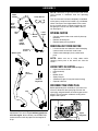 6
6
-
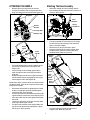 7
7
-
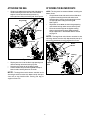 8
8
-
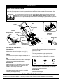 9
9
-
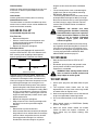 10
10
-
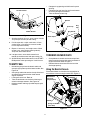 11
11
-
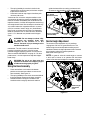 12
12
-
 13
13
-
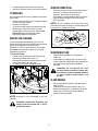 14
14
-
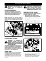 15
15
-
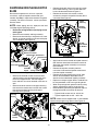 16
16
-
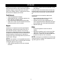 17
17
-
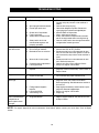 18
18
-
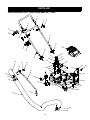 19
19
-
 20
20
-
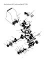 21
21
-
 22
22
-
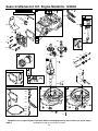 23
23
-
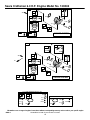 24
24
-
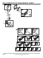 25
25
-
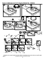 26
26
-
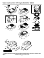 27
27
-
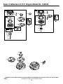 28
28
-
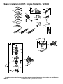 29
29
-
 30
30
-
 31
31
-
 32
32
-
 33
33
-
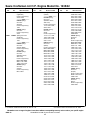 34
34
-
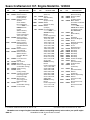 35
35
-
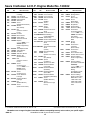 36
36
-
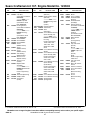 37
37
-
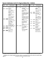 38
38
-
 39
39
-
 40
40
-
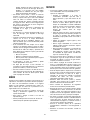 41
41
-
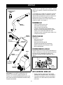 42
42
-
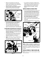 43
43
-
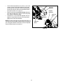 44
44
-
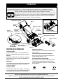 45
45
-
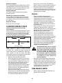 46
46
-
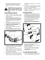 47
47
-
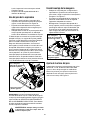 48
48
-
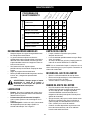 49
49
-
 50
50
-
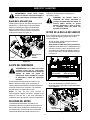 51
51
-
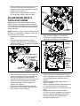 52
52
-
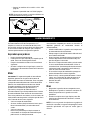 53
53
-
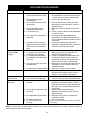 54
54
-
 55
55
-
 56
56


Sears 247.77055 Manual de usuario
- Tipo
- Manual de usuario
- Este manual también es adecuado para
En otros idiomas
- English: Sears 247.77055 User manual
Documentos relacionados
Otros documentos
-
Bolens 769-00407 Manual de usuario
-
Craftsman 247.770990 Manual de usuario
-
-
-
-
Craftsman Yard Vacuum 247.77012 Manual de usuario
-
-
-
-
Yard-Man 247.770380 Manual de usuario