HoMedics EnviraStation DWS-110 Instruction Manual And Warranty Information
- Categoría
- Relojes de mesa
- Tipo
- Instruction Manual And Warranty Information
Este manual también es adecuado para

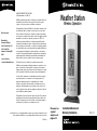
Weather Station
Wireless Operation
Instruction Manual and
Warranty Information
DWS-110
©2003 HoMedics, Inc. y sus compañías afiliadas, reservados todos los derechos. Envirastation™ es una
marca registrada de HoMedics Inc. y sus compañías afiliadas. Reservados todos los derechos.
IB-DWS110
GARANTÍA LIMITADA POR DOS AÑOS
(Válida únicamente en los EE.UU.)
HoMedics, garantiza este producto contra defectos en material y mano de
obra durante el período de dos años a partir de la fecha de compra
original, con las excepciones que se detallan a continuación.
Esta garantía de producto de HoMedics no cubre daños causados por un
uso inadecuado, abuso, accidente, la conexión de accesorios no autor-
izados, la alteración del producto o cualquier otra condición sin importar
cual sea que se encuentre fuera de nuestro control. Esta garantía es válida
únicamente si el producto es comprado y operado en los EE.UU. Un
producto que requiera modificación o adaptación para habilitar su fun-
cionamiento en cualquier país que no sea aquel para el que fue diseñado,
fabricado, aprobado y/o autorizado, o la reparación de productos dañados
por estas modificaciones no está cubierta bajo esta garantía. HoMedics no
será responsable de ningún tipo de daños incidentales, consecuentes o
especiales. Todas las garantías implícitas, incluyendo entre otras aquellas
garantías implícitas de idoneidad y comerciabilidad, están limitadas a la
duración total de dos años a partir de la fecha de compra original.
Para obtener un servicio cubierto por la garantía para su producto
HoMedics, puede entregar la unidad personalmente o enviarla por correo
junto con su recibo de compra fechado (como prueba de la compra), el
franqueo pagado, junto con un cheque o una orden de pago por el monto
de $5,00, pagadero a HoMedics, para cubrir los gastos de manipulación.
Una vez recibido, repararemos o reemplazaremos su producto, según lo
que sea apropiado y se lo enviaremos con el franqueo pagado. Si es
apropiado remplazar su producto, lo remplazaremos por el mismo
producto o un producto similar de acuerdo con nuestras opciones. La
garantía es válida únicamente a través de nuestro Centro de servicio. El
servicio realizado a este producto por cualquier otro diferente al Centro de
servicio HoMedics anulará la garantía.
Esta garantía le proporciona derechos legales específicos. Es posible que
usted tenga derechos adicionales que pueden variar de un estado a otro.
Debido a las regulaciones de ciertos estados, es posible que algunas de
las limitaciones y exclusiones no se apliquen en su caso.
Dirección postal:
Envirastation
Consumer Relations
Service Center Dept. 168
3000 Pontiac Trail
Commerce Township, MI
48390
correo electrónico:
El manual en
español
empieza a la
página 14

BEFORE YOU BEGIN:
1. IMPORTANT: Insert alkaline batteries into the home receiver unit first,
then the remote sensor.
2. Place the home unit as close as possible to the remote unit. This will
help with synchronization between the remote sensor and the home unit.
3. REMEMBER: Once you are ready to position your remote sensor and
home unit, ensure that the distance is not outside the effective
transmission range (100 feet). Some building materials and location
of the home unit or remote sensor can affect transmission quality and
range. Try various locations for best results.
BATTERY INSTALLATION
Home Receiver:
Lift off the battery cover on the back of the unit. Install 2 alkaline
AA batteries according to the polarity indicated. Close the battery cover.
Remote Sensor
:
Remove the attached bracket stand. Loosen the 2 screws securing the
battery cover with a small screwdriver and remove. Insert 2 alkaline AA
batteries according to the polarity direction indicated. Replace the cover
and tighten the 2 screws.
NOTE: There are no consumer serviceable parts. All questions or
service request should directed to our consumer relations department.
(See Warranty section for contact information.)
SETTING UP THE WIRELESS
THERMOMETER:
If you encounter any difficulties in setting up your wireless thermometer
system, please contact Consumer Relations.
• For the first installation, always insert alkaline batteries to the
home unit FIRST and then the remote sensor(s). (See BATTERY
INSTALLATION section)
• Your new RF Thermometer is built with random security code technology,
the home unit will learn the random code of the first remote sensor and
log it in as channel 1. Channel 2 and Channel 3 will be registered in the
same way if additional sensors are used. This unit can monitor up to 3
separate sensors.
• Once a channel is registered, it will not accept any new sensors.
However, registered channels can be erased by removing the batteries
in the remote sensor or the home unit.
• When replacing batteries for the remote sensor- Remember to clear the
corresponding channel of the home unit by removing the batteries. –OR–
Select the respective channel of the sensor by pressing the CHANNEL
button. Hold the CHANNEL button for 3 seconds to clear the registration.
• When replacing batteries for the home receiver- Please remove the
batteries of all remote sensors. Once you have replaced the home
receiver batteries, re-install the batteries to the sensors according to the
desired channel sequence. This will ensure that the unit and the remote
sensors are properly synchronized.
• Press the Tx button on the back of remote sensor to verify the RF reception.
• It is recommended to test the units next to each other to ensure that both
the remote sensor and home receiver are properly synchronized.
NOTE: Keep the remote sensor out of direct sunlight and rain.
Do not mount on metal surface.
2
3

5
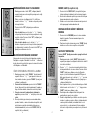
SNOOZE/ LIGHT
1. Press the SNOOZE/ LIGHT button for an
extended backlight.
2. In snooze alarm mode, press this button to trigger
a repetitive snooze alarm.
3. When normal alarm mode is selected, press the button to
turn off alarm for one day.
MAX/MIN MEMORY SETTINGS
1. Press ”MAX/ MIN“ button to view the maximum values for
5 seconds. Press again to view the minimum values.
2. To clear the memory record, press “CLEAR” while the
respective values displaying on screen.
TEMPERATURE ALERT
Press “ALERT” to turn temperature alert on and off.
1. Hold “ALERT” button for 3 seconds to enter the alert
setting mode. The indoor icon will flash.
2. Press “ +, - ” to select the between indoor temperature or
remote sensor reading to be alerted to. Press “ALERT” to
confirm your selection. The Upper pointer and the value on
the LCD display will flash. Enter the desired upper limit
with the “ +, - ” buttons, press “ALERT” to confirm your
selection and then go to the lower limit setting.
3. Now the Lower pointer and value will be flashing. Enter the
desired lower limit with “ +, - ” buttons, then press
“ALERT” to confirm and exit.
4. You may enter an alert setting for the indoor temp and for
the remote sensor.
5. When temperature hits the limit of your preset levels,
the Upper/Lower pointers and the temperature of the
respective channel (indoor or remote sensor) will flash with
an audible alarm. Press any button on the home receiver
to acknowledge and stop the alarm.
SETTING CLOCK & CALENDAR
1. Hold “SET ” button for 3 seconds until you hear a beep
to enter clock set.
2. First, select 12 hour or 24 hour setting using the “ + , - ”
buttons located on the back of the home receiver.
Press “ SET ” button to confirm your selection.
3. Select Hour - Use the “ + , - ” buttons located on the
back of the home receiver to adjust hour setting.
Press “ SET ” button to confirm your selection.
4. Select Minute - Use the “ + , - ” buttons located on the
back of the home receiver to adjust minute setting.
Press “ SET ” button to confirm your selection.
CENTIGRADE/FAHRENHEIT SELECTION
You can now select either Centigrade or Fahrenheit
temperature readings. Use the “ - “ button located on the
back of the home receiver to select between Centigrade or
Fahrenheit readings.
SETTING ALARM TIME
1. Hold the “CLEAR” button for 3 seconds. Press “ + , - “
to enter the desired Hr/ Min values and press “CLEAR”
to confirm setting.
2. To view alarm time - Press “CLEAR” button. Alarm time
will display for 5 seconds and then resume to normal
clock thereafter.
3. To select between daily alarm and snooze alarm -
Press “ + “ button on the back of the unit.
4. The home receiver will provide either a daily alarm, which
last for 2 minutes or a snooze mode where the alarm will
repeat every 8 minutes until manually cleared
(see SNOOZE/LIGHT section below.)
4

LOW BATTERY INDICATION
Low battery indication is available for the home receiver and the remote
sensor. Replace the batteries and follow the setup procedure as mentioned
in this instruction manual.
MAINTENANCE AND CARE INSTRUCTIONS
• Extreme temperatures, shock or areas of unusual vibration should be
avoided to prevent damage to the units.
• Clean the units using only a soft, damp cloth to wipe.
Do not use solvents, abrasives, detergents or other strong cleaning
agents. After cleaning, wipe surfaces with a dry cloth.
• Do not submerge units in water or other liquids.
• Do not subject the units to extremely severe temperatures - DO NOT
PLACE UNITS INTO OVENS, FREEZERS or MICROWAVE UNITS.
NOTE: Opening the housing of either the Remote Sensor or the Home
Unit will invalidate your warranty. Do not attempt to repair this unit –
There are no consumer serviceable parts.
6
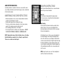
MOUNTING INSTRUCTIONS
Both the Home Unit and Remote Sensor come with a table
stand or they can be wall mounted.
Table Top -
For the home unit, simply attach the stand provided.
For the remote sensor, simply fold out the attached stand
from the mounting bracket.
Wall Mounting -
For the Home Unit - Remove the table top stand from the
bottom of the unit. Fix a screw (not included) into the
desired wall and place the home unit onto the screw using
the back side hanging hole.
For the Remote Sensor - Fix two screws (not included) into
the desired hanging location using the mounting bracket
holes on the remote sensor as a template. Ensure that the
screws are placed vertically (in a straight line up/down) along
the surface and that there is proper distance between each
screw to hang the mounting bracket. Align the hanging holes
of the mounting bracket with the two screws and place unit
onto the screws.
NOTE: Keep the remote sensor out of direct sunlight and
rain. Do not mount on a metal surface.
7

TROUBLE SHOOTING
Indoor and Outdoor temperatures do not match when
placed next to each other -
Each sensor is manufactured to be +/- 1 degree in accuracy under normal
conditions. So it is possible to have up to two degrees difference shown on
the separate temperature sensors (one could be “+1 degree” and the other
“-1 degree”. Additionally, the calibration curve is different between the two
units because of the greater temperature range of the outdoor sensor. Errors
are usually noted on the extreme ends of the temperature ranges.
Base unit is not accepting remote transmissions -
The units may not be properly synchronized or the batteries may need to be
replaced. See “SETTING UP THE WIRELESS THERMOMETER” section
beginning on page 2 of the instructions for detailed instructions. With the
two units next to each other, attempt synchronization. Remember to always
place the remote sensor within the effective transmission range and away
from large metal surfaces.
What is the recommended battery type?
Your units will come with 4 “AA” alkaline batteries (2 “AA” batteries required
for each unit). We recommend using only alkaline batteries for replacements.
Where can I mount the remote sensor?
To get accurate readings and to prolong the life of your sensor, we
recommend that you mount it out of direct sunlight and rain. Fog and mist
will not affect the sensor, but large volumes of soaking rain may. To guard
against this, we recommend that you mount it under the eve of your house,
your garage or any other suitable place that will keep it out of direct sun
and rain. Do not mount on a metal surface.
8 9
SPECIFICATIONS
Range of temperature/humidity measurement:
Indoor temp.: +32 F to +122 F (-5 C to + 50 C)
Remote sensor: -4 F to +140 F (-20 C to +60 C)
Channel: max. 3 remote sensors
Temp. alert: Indoor Temp and Ch 1
Transmission: max. 100 ft. (30 m) open area, RF434 MHz
Resolution: 0.1 degree for temperature
Clock: Quartz
Batteries: AA x 2 pcs for main unit, AA x 2 pcs for
remote sensor

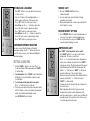
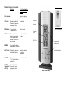
Remote Sensor/
Channel Indicator
Indoor
Temperature
Reading
LCD Clock
Snooze Button/
Backlight
Outdoor
Temperature
Reading
REMOTE SENSOR
HOME RECEIVER
Name and Functions of Buttons:
Functions
If button is held
down for 3 seconds
SET - - Enter clock & calendar
setting
UP+ 1 step forward Alarm, Fast advance
Snooze Alarm on/ off
DOWN -/ 1 step backward Fast backward
C/F Setting
CLEAR Clear memory at Max/ Min Alarm time setting
display Read alarm time 5
sec at normal mode
MAX/MIN Read maximum/ minimum
record 5 sec
ALERT Temp alert on/ off Enter temp alert setting
CHANNEL Select Channel 1,2,3, Delete current channel
auto scroll
SNOOZE/ Backlight on 5 seconds,
LIGHT Trigger snooze alarm,
stop alarm
10 11

©2003 HoMedics, Inc. and its affiliated companies, all rights reserved. Envirastation™ is a trademark of
HoMedics, Inc. and its affiliated companies. All rights reserved.
IB-DWS110
TWO YEAR LIMITED WARRANTY
(Valid in USA only)
HoMedics guarantees this product free from defects in material and work-
manship for a period of two years from the date of original purchase,
except as noted below.
This HoMedics product warranty does not cover damage caused by
misuse or abuse; accident; the attachment of any unauthorized
accessory; alteration to the product; or any other conditions whatsoever
that are beyond our control. This warranty is effective only if the product is
purchased and operated in the USA. A product that requires modification
or adaptation to enable it to operate in any country other than the country
for which it was designed, manufactured, approved and/or authorized, or
repair of products damaged by these modifications is not covered under
warranty. HoMedics shall not be responsible for any type of incidental,
consequential or special damages. All implied warranties, including but
not limited to those implied warranties of fitness and merchantability, are
limited in the total duration of two years from the original purchase date.
To obtain warranty service on your HoMedics product, either hand deliver
or mail the unit and your dated sales receipt (as proof of purchase),
postpaid, along with check or money order in the amount of $5.00
payable to HoMedics to cover handling.
Upon receipt, we will repair or replace, as appropriate, your product and
return it to you, postpaid. If it is appropriate to replace your product, we
will replace the product with the same product or a comparable product
at our option. Warranty is solely through our Service Center. Service of
this product by anyone other than HoMedics Service Center voids
warranty.
This warranty provides you with specific legal rights. You may have
additional rights which may vary from state to state. Because of indi-
vidual state regulations, some of the above limitations and exclusions
may not apply to you.
Mail To:
Envirastation
Consumer Relations
Service Center Dept. 168
3000 Pontiac Trail
Commerce Township, MI
48390
e-mail:
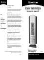
Estación meteorológica
Funcionamiento inalámbrico
Manual de instrucciones e
Información de garantía
DWS-110
Garantía limitada por dos años

ANTES DE COMENZAR:
1. IMPORTANTE: Introduzca las pilas alcalinas en la unidad receptora interior, y
luego en el sensor exterior.
2. Coloque la unidad interior tan cerca de la unidad exterior como sea posible.
Esto ayudará a la sincronización entre el sensor exterior y la unidad interior.
3. RECUERDE: Una vez que esté listo para colocar su sensor exterior y su
unidad interior en el lugar, asegúrese de que la distancia no esté fuera del
ámbito de transmisión efectivo (100 pies/ 30,5 m). Algunos materiales de con-
strucción y la ubicación de la unidad interior o del sensor exterior pueden
afectar la calidad y el ámbito de la transmisión. Para obtener mejores
resultados, pruebe con varias ubicaciones.
INSTALACIÓN DE LAS PILAS
Receptor interior:
Levante la tapa del compartimiento de las baterías en la parte posterior de la
unidad. Instale 2 pilas alcalinas AA de acuerdo a la polaridad que se indica.
Cierre la tapa del compartimiento de las pilas.
Sensor exterior
:
Retire el pie de soporte que se adjunta. Afloje los 2 tornillos que aseguran la tap
a del compartimiento de las baterías con un destornillador pequeño, y retírela.
Introduzca 2 pilas alcalinas AA de acuerdo con la dirección de la polaridad que
se indica. Vuelva a colocar la tapa y ajuste los 2 tornillos.
ATENCIÓN: No hay piezas que necesiten servicio. Todas las preguntas o
solicitudes de servicio deberán ser dirigidas a nuestro departamento de rela-
ciones con el consumidor. (Vea la información de contacto en la sección de
Garantía.
14
15
CÓMO INSTALAR EL TERMÓMETRO INALÁMBRICO:
Si usted tiene alguna dificultad para instalar su sistema de termómetro
inalámbrico, sírvase ponerse en contacto con Relaciones con el consumidor.
• Para la primera instalación, siempre coloque las pilas alcalinas PRIMERO en la
unidad interior y luego en el (los) sensor(es) exterior(es). (Vea la sección
INSTALACIÓN DE LAS PILAS)
• Su nuevo termómetro de RF (frecuencia de radio) está construido con tec-
nología de códigos de seguridad aleatorios, la unidad interior captará el
código aleatorio del primer sensor exterior y lo registrará en él como canal 1.
Los canales 2 y 3 se registrarán del mismo modo en caso de usar sensores
adicionales. Esta unidad puede monitorear hasta 3 sensores diferentes.
• Una vez que se registra un canal, no aceptará ningún sensor nuevo. Sin
embargo, los canales registrados pueden borrarse retirando las pilas del
sensor exterior o de la unidad interior.
• Cuando cambie las pilas del sensor exterior - recuerde borrar el canal corre-
spondiente de la unidad interior retirando también las pilas. O seleccione el
canal del sensor respectivo presionando el botón CHANNEL (canal). Mantenga
presionado el botón CHANNEL (canal) durante 3 segundos para borrar el
registro.
•Cuando cambie las baterías del receptor interior - sírvase retirar las pilas de
todos los sensores exteriores. Una vez que haya cambiado las pilas del
receptor interior, vuelva a instalar las baterías de los sensores, de acuerdo a la
secuencia de canales deseada. Esto asegurará que la unidad y los sensores
exteriores estén sincronizados de manera adecuada.
• Presione el botón Tx en la parte posterior del sensor exterior para verificar la
recepción de RF.
• Se recomienda probar las unidades una junto a la otra para asegurarse de que
ambas, el sensor exterior y el receptor interior, estén sincronizadas de manera
adecuada.
ATENCIÓN: Mantenga el sensor exterior protegido de la luz solar directa y
de la lluvia. No lo instale sobre superficies metálicas.

16
CONFIGURACIÓN DEL RELOJ Y EL CALENDARIO
1. Mantenga presionado el botón “SET” (configurar) durante 3
segundos hasta que escuche un pitido para ingresar la config-
uración del reloj.
2. Primero, seleccione la configuración de 12 0 de 24 horas
usando los botones “ + ” y “ - ” ubicados en la parte posterior
del receptor interior.
Presione el botón “SET” (configurar) para confirmar su
selección.
3. Selección de la hora - use los botones “ + ” y “ - ” ubicados
en la parte posterior del receptor interior para ajustar la config-
uración de la hora. Presione el botón “SET” (configurar) para
confirmar su selección.
4. Selección de los minutos - use los botones “ + ” y “ - ”
ubicados en la parte posterior del receptor interior para ajustar
la configuración de los minutos. Presione el botón “SET” (con-
figurar) para confirmar su selección.
SELECCIÓN DE CENTÍGRADOS/ FAHRENHEIT
Ahora puede seleccionar la lectura de la temperatura en grados
Centígrados o en grados Fahrenheit. Use el botón “ - ” ubicado en
la parte trasera del receptor interior para seleccionar entre lecturas
en Centígrados o en Fahrenheit.
CÓMO CONFIGURAR LA HORA DE LA ALARMA
1. Mantenga presionado el botón “CLEAR” (borrar) durante 3
segundos. Presione “ + ” y “ - “ para ingresar los valores de
horas/ minutos deseados y presione "CLEAR” (borrar) para
confirmar la configuración.
2 Para ver la hora de la alarma - presione el botón “CLEAR”
(borrar). Aparecerá la hora de la alarma durante 5 segundos y
luego, de ahí en adelante, retomará la hora del reloj normal.
3. Para seleccionar entre la alarma diaria y la alarma de
repetición - presione el botón “ + ” en la parte posterior de la
unidad.
4. El receptor interior proporcionará ya sea una alarma diaria,
que dura 2 minutos, o un modo de alarma de repetición, en el
cual la alarma se repetirá cada 8 minutos hasta que sea
detenida manualmente (vea la sección SNOOZE/ LIGHT (de
repetición/ luz) a continuación).
17
SNOOZE/ LIGHT (de repetición/ luz)
1. Presione el botón SNOOZE/LIGHT (de repetición/ luz) para
obtener un tiempo de iluminación de fondo más prolongado.
2. En el modo de alarma de repetición, presione este botón para
disparar una alarma de sonidos reiterados.
3. Cuando se selecciona el modo de alarma normal, presione el
botón para apagar la alarma durante un día.
CONFIGURACIÓN DE MÁXIMO Y MÍNIMO DE
MEMORIA
1. Presione el botón “MAX/ MIN”para ver los valores máximos
durante 5 segundos. Presione nuevamente para ver los
valores mínimos.
2. Para borrar el registro de memoria, presione “CLEAR” (borrar)
mientras se vean los valores respectivos en la pantalla.
ALERTA DE TEMPERATURA
Presione “ALERT” (alerta) para encender o apagar la alerta de
temperatura.
1. Mantenga presionado el botón “ALERT” (alerta) durante 3
segundos para ingresar la configuración del modo de alerta. El
ícono interior destellará.
2. Presione “ + ” y “ – “ para seleccionar entre alerta de lectura
de temperatura interior o de sensor exterior. Presione el botón
“ALERT” (alerta) para confirmar su selección. El puntero
superior y el valor destellarán en la pantalla LCD. Ingrese el
límite superior deseado con los botones “ + ” y “ - ”, presione
“ALERT” (alerta) para confirmar su selección y luego vaya a
configurar el límite inferior.
3. Ahora el puntero inferior y el valor destellarán. Ingrese el límite
inferior deseado con los botones “ + “ y “ - ”; luego presione
“ALERT” (alerta) para confirmar, y salga.
4. Puede ingresar una configuración de alerta para la tem-
peratura interior y para el sensor exterior.
5. Cuando la temperatura llega a l límite de sus niveles preselec-
cionados, los punteros superior e inferior y la temperatura del
canal respectivo destellarán (en la unidad interior o en el
sensor exterior), y se oirá una alarma. Presione cualquier
botón en el receptor interior para aceptar el aviso y detener la
alarma.

18
SEÑAL DE PILAS DESCARGADAS
La señal de pilas descargadas está disponible tanto para el receptor interior
como para el sensor exterior. Cambie las pilas y siga el procedimiento de ajuste
tal como se explica en este manual de instrucciones.
INSTRUCCIONES DE MANTENIMIENTO Y CUIDADO
• Las temperaturas extremas, las descargas o las áreas de vibración inusual
deberán evitarse para prevenir daños a las unidades.
• Limpie las unidades usando solamente un paño suave y húmedo para
repasarlas. No use solventes, abrasivos, detergentes ni ningún otro agente de
limpieza fuerte. Después de limpiar las superficies, séquelas con un paño
seco.
• No sumerja las unidades en agua ni en ningún otro líquido.
• No someta las unidades a temperaturas extremas - NO COLOQUE LAS
UNIDADES EN HORNOS, CONGELADORES ni UNIDADES DE
MICROONDAS.
ATENCIÓN: Si abre el armazón del sensor exterior o de la unidad interior,
invalidará su garantía. No intente reparar esta unidad – No hay piezas que
necesiten servicio.
19
INSTRUCCIONES DE INSTALACIÓN
Tanto la unidad interior como el sensor exterior vienen con un
soporte de pie, o pueden montarse en la pared.
Para colocar en una mesa:
en el caso de la unidad interior, simplemente colóquele el pie
que se adjunta. En el caso del sensor exterior, simplemente
doble el pie que se adjunta en el soporte de montaje.
Instalación en la pared:
en el caso de la unidad interior, retire el soporte de pie de la
parte de abajo de la unidad. Sujete un tornillo (que no se incluye)
a la pared deseada y coloque la unidad interior sobre el tornillo,
usando el orificio para colgar que tiene en la parte posterior.
En el caso del sensor exterior: sujete dos tornillos (que no se
incluyen) en el lugar donde desea colgarlo, usando los orificios
del soporte para colgar en el sensor exterior como patrón.
Asegúrese de que los tornillos estén colocados verticalmente (en
línea recta, de arriba hacia abajo) a lo largo de la superficie, y
que hay una distancia adecuada entre cada uno de los tornillos
para colgar el soporte de montaje. Alinee los orificios para colgar
del soporte de montar con los dos tornillos y coloque la unidad
sobre los tornillos.
ATENCIÓN: Mantenga el sensor exterior protegido de la luz solar
directa y de la lluvia. No lo instale sobre una superficie metálica.

20 21
DIAGNÓSTICO Y RESOLUCIÓN DE PROBLEMAS
Las temperaturas interiores y exteriores no coinciden cuando se
colocan una junto a la otra –
Cada sensor está fabricado para tener una tolerancia de +/- 1 grado en la pre-
cisión, bajo condiciones normales. Por lo tanto es posible que haya hasta dos
grados de diferencia en los distintos sensores de temperatura (uno puede tener
“+ i grado” y el otro “- 1 grado”. Además, la curva de calibración es diferente
entre las dos unidades debido a la mayor variación de temperatura del sensor
exterior. Generalmente se ven los errores en los extremos de las variaciones de
temperatura.
La unidad base no está aceptando las transmisiones remotas -
Puede que las unidades no estén sincronizadas de manera adecuada o que sea
necesario cambiar las baterías. Vea la sección “CÓMO CONFIGURAR EL
TERMÓMETRO INALÁMBRICO” que comienza en la página 2 de las instruc-
ciones, para obtener más detalles. Con las dos unidades cerca una de otra,
intente la sincronización. Recuerde colocar siempre el sensor exterior dentro del
ámbito de transmisión efectivo y lejos de superficies metálicas grandes.
¿Cuál es el tipo de pila recomendado?
Sus unidades viene con 4 pilas alcalinas AA (se requieren 2 pilas AA para cada
unidad). Recomendamos que únicamente utilice pilas alcalinas cuando las cambie.
¿Dónde puedo instalar el sensor exterior?
Para obtener lecturas precisas y para extender la vida útil de su sensor, sugerimos
que lo instale donde quede a salvo de la luz solar directa y de la lluvia. La niebla y
la bruma no afectarán al sensor, pero puede que sí lo afecten grandes volúmenes
de lluvia. Para protegerlo de esto, recomendamos que lo instale bajo el alero de
su casa, su cochera o cualquier otro lugar adecuado que lo mantenga al reparo
del sol directo y la lluvia. No lo instale sobre una superficie metálica.
ESPECIFICACIONES
Ámbito de medición de temperatura/ humedad:
Temperatura interior: de +32ºF a +122ºF (de -5ºC a 50ºC)
Sensor exterior: de -4ºF a +140ºF (de -20ºC a +60ºC)
Canal: máximo 3 sensores exteriores
Alerta de temperatura: Temp. interior y Canal 1
Transmisión: máximo 100 pies (30 m) de área abierta, RF (fre-
cuencia de radio) 434 MHz
Resolución: 0,1 grado para temperatura
Reloj: de cuarzo
Pilas: 2 unidades de AA para la unidad principal, 2
unidades de AA para el sensor exterior

22 23
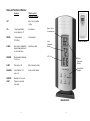
Nombre y funciones de los botones:
Funciones Si el botón se mantiene
presionado durante 3
segundos
SET (configurar) - - Ingrese la configuración
del reloj y del calendario
UP+ (arriba) Alarma, 1 paso adelante, Avance rápido
Encendido y apagado de
la alarma de repetición
DOWN (abajo) -/ 1 paso hacia atrás Retroceso rápido
Configuración en º C/F
CLEAR% (borrar) Borra el máx/mín de la Configuración de hora de
memoria que se muestra. la alarma
Lee el tiempo de alarma
durante 5 segundos en el
modo normal
MÁX/MÍN Lee los registros máximo y
mínimo durante 5 segundos
ALERT (alerta) Encendido y apagado de Ingresa la configuración
la alerta de temperatura de la alerta de
temperatura
CHANNEL (canal) Selecciona los canales Borra el canal actual
1, 2, 3, avance y retroceso
automáticos
SNOOZE Iluminación de fondo en
(de repetición)/ 5 segundos, Dispara
LIGHT (luz) la alarma de repetición,
detiene la alarma
Indicador del
sensor exterior y
del canal
Lectura de la
temperatura
interior
Reloj LCD
Botón de alarma de
repetición/ luz de fondo
Lectura de la tem-
peratura exterior
SENSOR EXTERIOR
RECEPTOR INTERIOR
-
 1
1
-
 2
2
-
 3
3
-
 4
4
-
 5
5
-
 6
6
-
 7
7
-
 8
8
-
 9
9
-
 10
10
-
 11
11
-
 12
12


HoMedics EnviraStation DWS-110 Instruction Manual And Warranty Information
- Categoría
- Relojes de mesa
- Tipo
- Instruction Manual And Warranty Information
- Este manual también es adecuado para
En otros idiomas
- English: HoMedics EnviraStation DWS-110
Documentos relacionados
-
HoMedics DWS-170 Manual de usuario
-
-
-
-
-
-
-
-
-