
1
R. 06/23 815 804
SAMOA Industrial, S.A. · Pol. Ind. Porceyo, I-14 · Camino del Fontán, 831 · 33392 - Gijón - Spain · Tel.: +34 985 381 488 · www.samoaindustrial.com
2023_06_19-11:30
Parts and technical service guide
Guía de servicio técnico y recambio
Guide d’instructions et pièces de rechange
Bedienungsanleitung und Teileliste
Manual de Serviços Técnicos e Reposições.
Список деталей и руководство по техническому обслуживанию
Part No. / Cód. / Réf. / Art. Nr. /
Cód. / Деталь №:
157 000
157 004
FOOT OPERATED GREASE PUMP 2
BOMBA INDUSTRIAL DE ENGRASE A PEDAL 4
COMPRESSEUR A GRAISSE – PEDAL PUMP 6
HOCHDRUCK-FUSSPRESSE 8
BOMBA MANUAL DE PEDAL PARA GRAXA 10
НАСОС С НОЖНЫМ ПРИВОДОМ ДЛЯ КОНСИСТЕНТНОЙ СМАЗКИ 12
EN
ES
FR
PT
RU
DE

2815 804 R. 06/23
SAMOA Industrial, S.A. · Pol. Ind. Porceyo, I-14 · Camino del Fontán, 831 · 33392 - Gijón - Spain · Tel.: +34 985 381 488 · www.samoaindustrial.com
2023_06_19-11:30
EN
DESCRIPTION
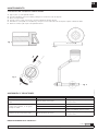
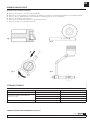
Very solid grease pump, very comfortable foot action. For all types of lubricants, with spring actionned grease compacting piston, to be used with
heavy greases. Maximum pressure 7350 psi (500 bar). Delivery per cycle: 0.07 ounces (2 g).
Very solid and easily transported 11 lb (5 kg), leak proof container. Pump with air purger, high pressure 2 m hose (140200) and nozzle with valve (121020).
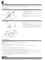
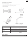
INSTALLATION
Fig. 1
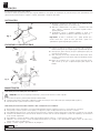
LOADING
Fig. 2
MAINTENANCE
1. With the spring unloaded, turn the grips until the lateral opening is obtained.
2. Lift the top part of the pump and replace the joint in a way that the lips of the said joint remain towards the bottom (fig. 1).
3. Assemble in the opposite way.
1. Screw the high pressure hose (1) to the outlet valve placed on the
bottom part of the pump (2).
2. To distribute grease, charge the container following instructions
stated in the next paragraph.
3. Then adjust the hydraulic nozzle at the greasing point and proceed
with the supply by means of pedal strokes.
Important: When accomplishing this movement let the pedal return to
its original position in order to allow the adequate amount of grease to
be loaded in the piston.
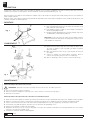
A. Firmly hold the pump on the floor by stepping on the base and
pulling up the rod (1) until the pin (2) surpasses the top opening
(detail).
B. In this position, turn the rod (1) until the pin(2) prevents it from
returning to its original position.
C. Turn the grips (3) until the rod and topo may be removed. Remove
the top part of the pump (4) and proceed to fill the container.
D. After the filling, turn the grips to original position and turn the rod
(1) until the pin crosses the top rut and releases the rod. Pressure is
now on the spring an follower.
WARNING! Before starting any work relieve the spring tension and reduce the pressure!
!
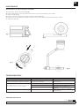
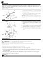
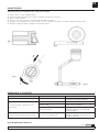
REPLACEMENT OF THE PISTON JOINT
REPLACEMENT OF THE TORSION SPRING AND PINION ASSEMBLY
1. Remove the top part of the pump, and place it upside down.Remove the inside screws and remove the base.
2. In this position, lift the pedal and remove the pin. Remove the torsion spring and/or pignon.
3. To replace the torsion spring, place the new one in its position and the pignon as per indications in fig. 2. Introduce the assembly axe-pedal.
4. Lift the inside end of the spring with the help of a screwdriver until pin bearing is surpassed (fig. 3). Introduce this piece completely.
5. To replace the axe-pinion assembly, dismount following instructions stated in paragraph 1 and 2.
6. Remove the cap nut and separate the axe from the pedal. Replace the axe in a way that the pin bearing is in line with the pedal and the smaller
diameter side of the said conical hole situated on the opposite side of the pedal (fig 4).
7. Mount the set as per paragraph. 3.

3
R. 06/23 815 804
SAMOA Industrial, S.A. · Pol. Ind. Porceyo, I-14 · Camino del Fontán, 831 · 33392 - Gijón - Spain · Tel.: +34 985 381 488 · www.samoaindustrial.com
2023_06_19-11:30
EN
MAINTENANCE
REPLACEMENT OF THE PUMP BODY ASSEMBLY
1. Follow steps 1 and 2 of the previous paragraph.
2. Place the pump with te correct side up and remove the three screws from the bottom of the container.
3. Remove the pump body.
4. Place the new body in position and screw the outlet valve without tightening.
5. Introduce the axe of the pedal in its bearing and screws the three screws situated on the bottom part of the container.
6. Tighten the outlet valve.
Fig. 1
Fig. 2
Fig. 3
Fig. 4
SYMPTOMS POSSIBLE CAUSES SOLUTIONS
Grease exits through the top part of the pump. The piston joint is damaged. Replace as per indications in paragraph:
“technical service”.
When applying pressure on the foot lever, grease
does not come out, or the flow diminishes.
The outlet valve is damaged. Replace the outlet valve.
There is dirt in the outlet valve seat. Cleaning of the seat.
The piston is damaged. Replace body valve assembly as per
indications
The pedal does not return to its original position. The torsion spring is broken. Replace as per indications in paragraph:
“technical service”.
TROUBLESHOOTING
SPARE PARTS SEE PAGE14-16

4815 804 R. 06/23
SAMOA Industrial, S.A. · Pol. Ind. Porceyo, I-14 · Camino del Fontán, 831 · 33392 - Gijón - Spain · Tel.: +34 985 381 488 · www.samoaindustrial.com
2023_06_19-11:30
ES
DESCRIPCIÓN
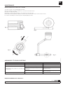
Bomba de engrase muy robusta, accionamiento muy confortable a pedal. Para todo tipo de lubricantes, con pistón de compactación de grasa
empujado por muelle para utilización con las grasas más duras. Presión máx.: 500 bar (7351 psi). Entrega por ciclo de pedal: 2 g (0.07 ounces).
Depósito estanco, muy robusto y fácilmente transportable de capacidad 5 kg (11 lb). Bomba con purgador de aire, flexible de alta presión de 2 m
(140200) y boquilla con válvula (121020).
INSTALACIÓN
Fig. 1
CARGA
Fig. 2
MANTENIMIENTO
1. Con el muelle en reposo, gire las empuñaduras hasta lograr la apertura lateral.
2. Levante la parte superior de la bomba y sustituya la junta de forma que los labios de la misma queden hacia abajo (fig. 1).
3. Monte en orden inverso.
¡ADVERTENCIA!: Antes de iniciar cualquier trabajo debe aliviar la tensión del muelle y reducir la presión.
!
SUSTITUCIÓN DE LA JUNTA DEL ÉMBOLO
SUSTITUCIÓN DEL MUELLE DE TORSIÓN Y DEL CONJUNTO PIÑÓN
1. Enrosque el flexible de alta presión (1) en la válvula de salida situada
en la parte inferior de la bomba (2).
2. Para suministrar grasa, realice la carga del depósito según se indica
en el siguiente apartado.
3. A continuación acople la boquilla hidráulica en el punto de engrase
y proceda al suministro actuando sobre el pedal (3).
Importante: Al realizar este movimiento deje que el pedal retorne
hasta el final de su recorrido para permitir así la carga adecuada de grasa
en el pistón.
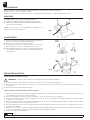
A. Sujete firmemente la bomba al suelo pisando sobre la base y tire de
la varilla (1) hasta que el pasador (2) supere la abertura superior
(detalle).
B. En esta posición, gire la varilla (1) hasta que el pasador (2) le impida
retornar a la posición inicial.
C. Gire las empuñaduras (3) hasta lograr la apertura lateral de las
mismas. Ahora es posible retirar la parte superior de la bomba (4) y
proceda a su llenado.
D. Después del llenado, coloque las empuñaduras en posición inicial y
gire la varilla (1) hasta lograr que el pasador traspase la hendidura
superior.
1. Retire la parte superior de la bomba y colóquela boca abajo. Retire los tornillos interiores y quite la base.
2. En esta posición, levante el pedal y saque el pasador mediante impactos en su cabeza. Extraiga el muelle de torsión y/o el piñón.
3. Para sustituir el muelle de torsión, coloque el nuevo en su posición y el piñón según se indica en fig. 2. Introduzca el conjunto eje-pedal.
4. Levante el extremo interior del muelle haciendo palanca con un destornillador hasta superar el alojamiento del pasador (fig. 3). Introduzca este
a fondo mediante impactos.
5. Para sustituir el conjunto eje-piñón, realice el desmontaje según los apartados 1 y 2. Quite la tuerca sombrerete y separe el eje y el pedal.
6. Sustituya el eje de forma que el alojamiento del pasador quede alineado con el pedal y con el extremo de menor diámetro de dicho taladro
cónico situado en el lado opuesto al pedal (fig. 4).
7. Monte el conjunto según el procedimiento del apartado 3.

5
R. 06/23 815 804
SAMOA Industrial, S.A. · Pol. Ind. Porceyo, I-14 · Camino del Fontán, 831 · 33392 - Gijón - Spain · Tel.: +34 985 381 488 · www.samoaindustrial.com
2023_06_19-11:30
ES
MANTENIMIENTO
SUSTITUCIÓN DEL CONJUNTO CUERPO BOMBA
Fig. 1
Fig. 2
Fig. 3
Fig. 4
ANOMALÍAS Y SOLUCIONES
1. Siga los pasos 1 y 2 del apartado anterior.
2. Coloque la bomba de nuevo boca arriba y extraiga los 3 tornillos del fondo del depósito.
3. Retire el cuerpo bomba.
4. Coloque el nuevo cuerpo en posición y enrosque la válvula de salida sin apretar.
5. Introduzca el eje del pedal en su alojamiento y enrosque los tres tornillos del fondo del depósito. Apriete la válvula de salida.
6. Finalice el montaje según el paso 3 del apartado anterior.
SÍNTOMAS POSIBLES CAUSAS SOLUCIONES
Salida de grasa por la parte superior de la
bomba. Junta de émbolo deteriorada. Sustituya según se indica en el apartado
“Servicio técnico”.
Al actuar sobre la palanca, no sale grasa o
disminuye el caudal.
Deterioro de la válvula de salida. Sustituya válvula de salida.
Impurezas en el asiento de la válvula de salida. Limpie del asiento.
Pistón deteriorado. Sustituya conjunto cuerpo bomba según se
indica en el apartado “Servicio técnico”.
El pedal no retorna a su posición inicial. Rotura del muelle de torsión. Sustituya según se indica en el apartado
“Servicio técnico”.
DIBUJO DE RECAMBIOS EN LA PÁGINA14-16

6815 804 R. 06/23
SAMOA Industrial, S.A. · Pol. Ind. Porceyo, I-14 · Camino del Fontán, 831 · 33392 - Gijón - Spain · Tel.: +34 985 381 488 · www.samoaindustrial.com
2023_06_19-11:30
FR
DESCRIPTION
Compresseur a graisse très robuste, action à pédale très pratique. Pour tous types de lubrifiants, avec piston suiveur poussée par ressort pour
utilisation avec les graisses les plus épaisses. Pression maximum : 500 bar (7350 psi) Débit par cycle : 2 g.
Réservoir étanche, très robuste et facil a transporter. Capacité 5 kg (11 lb). Pompe avec purgeur d’air, flexible haute pression de 2 m (140200) et
agrafe a clapet (121020).
Depósito estanco, muy robusto y fácilmente transportable de capacidad 5 kg (11 lb). Bomba con purgador de aire, flexible de alta presión de 2 m
(140200) y boquilla con válvula (121020).
MONTAGE
Fig. 1
CHARGEMENT
Fig. 2
MAINTENANCE
ATTENTION!: Avant toute intervention à soulager la tension du ressort et de réduire la pression!
!
REMPLACEMENT DU JOINT DU PISTON
REMPLACEMENT DU RESSORT DE TORSION ET ENSEMBLE PIGNO
1. Visser le flexible haute pression (1) sur la valve de sortie située sur la
partie inférieure de la pompe (2).
2. Pour distribuer la graisse, remplir le reservori d’après les instructions
décrites au paragraphe suivant.
3. Puis placer l’agrafe hydraulique sur le point de graissage et proceder
a la distribution en actionnant la pedale (3).
Important: Lorsque cette action est réalisée, laisser la pédale retourner
a sa position initiale afin de permettre un chargement en graisse correct
de la chambre de compression.
A. Maintenir fermement la pompe au sol en montant sur sa base et tirer
de la tige (1) jusqu’à ce que la goupille (2) depasse l’ouverture
superieure (détail).
B. Dans cette poisition, tourner la tige (1) d’un quart de tour pour
verrouillage.
C. Tourner les manettes (3) jusqu’à obtenir l’ouverture. Retirer le
couvercle de la pompe (4) et proceder a son remplissage.
D. Aprés le remplissage, refixer le couvercle et deverrouiller la tige.
1. Avec le ressort relaché, tourner les manettes.
2. Retirer le couvercle et templacer le joint de façon a ce que les lèvres de e-ci restent vers le bas (fig. 1).
3. Remonter en sens inverse.
1. Retirer le couvercle de la pompe et retourner celle-ci. Retirer les vis intérieures et enlever la base.Dans cette position, lever la pédale et retirer la goupille.
2. Extraire le ressort de torsion, mettre le nouveau ressort en position et le pignon selon les indications de la fig. 2. Introduire l’ensemble axe-pedale.
3. Lever le côte interieur du ressort avec l’aide d’un tournevis jusqu’à dépasser le siège de la goupille (fig. 3). Introduire celui ci a fond.
4. Pour changer l’ensemble axe-pignon, démonter selon les instructions des paragraphes 1 et 2.
5. Enlever l’écrou chapeau et séparer l’axe de la pédale.
6. Remplacer l’axe de façon a ce que le siège de la goupille soit en ligne avec la pédale et l’extrémité ave le plus petit diamètre de ce trou conique
situé sur le coté opposé à la pédale (fig. 4).
7. Assembler en suivant les intructions du paragraph 3.

7
R. 06/23 815 804
SAMOA Industrial, S.A. · Pol. Ind. Porceyo, I-14 · Camino del Fontán, 831 · 33392 - Gijón - Spain · Tel.: +34 985 381 488 · www.samoaindustrial.com
2023_06_19-11:30
FR
MAINTENANCE
REMPLACEMENT DU CORPS DE LA POMPE
Fig. 1
Fig. 2
Fig. 3
Fig. 4
ANOMALIES ET LEURS SOLUTIONS
1. Suivre les points 1 et 2 du paragraphe précédent.
2. Placer la pompe sur sa base et extraire les 3 vis situées au fond du réservoir.
3. Enlever le corps de la pompe.
4. Mettre le nouveau corps en position e visser la valve de sortie sans serrer.
5. Introduire l’axe de la pédale en position et visser les trois vis du fond du réservoir. Serrer la valve de sortie.
6. Terminer l’assemblage en suivant le points 3 du paragraphe precedent.
PROBLÈMES CAUSES POSSIBLES SOLUTIONS
Sortie de graisse partie supérieur de la pompe. Joint du piston endommagé. Remplacer. Voir “Donées techniques”.
En actionnant le levier, la graisse ne coule pas ou
le debi diminue.
Agrafe hydraulique endommagé. Substitution de la valve de sortie.
Impuretés dans le siège de l’agraphe
hydraulique. Nettoyage du siège.
Piston endommagé. Substitution ensemble corps pompe. Voir
“Donées techniques”.
La pedale ne retourne pas a sa position initiale. Rupture du ressort de torsion. Remplacer. Voir “Donées techniques”.
DIBUJO DE RECAMBIOS EN LA PÁGINA14-16

8815 804 R. 06/23
SAMOA Industrial, S.A. · Pol. Ind. Porceyo, I-14 · Camino del Fontán, 831 · 33392 - Gijón - Spain · Tel.: +34 985 381 488 · www.samoaindustrial.com
2023_06_19-11:30
DE
BESCHREIBUNG
Robuste Fettpumpe, einfache Handhabung durch Fussbedienung. Geeignet für Fette bis Konsistenzklasse 2.
Druckleistung ca. 500 bar, Förderleistung 2 g/Hub.
Behälter mit 5 kg Inhalt mit Fußpedal und Tragegriff, 2 m Abschmierschlauch (140200) mit 4-Backen-Mundstück (121020).
MONTAGE
Fig. 1
CHARGEMENT
Fig. 2
REPARATURANLEITUNG
WARNUNG!: Vor Beginn jeglicher Arbeiten die Federspannung entlasten und Druck abbauen!
!
ERSETZEN DER KOLBENDICHTUNG
ERSETZEN DER TORSIONSFEDER UND DES RITZELS
1. Abgabeschlauch (1) befestigen an Pumpenausgang (2).
2. Mundstück von Abgabeschlauch auf Schmiernippel befestigen.
3. Fußhebel (3) betätigen um Druck aufzubauen and abzuschmieren.
(siehe auch „Inbetriebnahme“).
Fußhebel (3) soll immer in die Ausgangsposition zurückkehren um
maximale Fett zufuhr zu gewährleisten.
A. Pumpe mit dem Fuß auf Fußplatte kräftig auf den Boden halten und
Hebel (1) hochziehen bis Sperrstift (2) sichtbar wird.
B. Hebel (1) in diese Position drehen und verrriegeln.
C. Tragegriffe (3) drehen bis sie zurück geschoben werden können.
Obere Pumpenteil (4) entfernen und Behälter füllen mit Fett.
D. Nach Befüllung Tragegriffe (3) wieder in Ausgangs-Position zurück
schieben. Hebel (1) entriegeln. Behälter steht jetzt unter Druck und
ist Einsatzbereit.
1. Entlasten Sie die Feder und drehen Sie die seitlichen Griffe auf, bis Sie diese nach unten klappen können.
2. Heben Sie den oberen Teil der Pumpe ab, und ersetzen Sie die Kolbendichtung. Achten Sie darauf, dass die Lippen der Dichtung nach unten
zeigen (Abb. 1).
3. Die Montage erfolgt in umgekehrter Reihenfolge.
1. Entfernen Sie den oberen Teil der Pumpe (siehe Absatz 1) und drehen Sie sie den Behälter um. Entfernen Sie an der Unterseite des Gehäuses die
drei Schrauben und entfernen Sie den Fuß der Pumpe.
2. Heben Sie das Pedal an und entfernen Sie den Stift. Entfernen Sie die Torsionsfeder und / oder das Ritzel.
3. Um die Torsionsfeder zu ersetzen, montieren und positionieren Sie die neue Feder und das Ritzel im Verhältnis zum Kolben entsprechend Abb.
2. Montieren Sie die Pedalwelle.
4. Heben Sie das innere Ende der Feder mit Hilfe eines Schraubendrehers an, bis es die Stift-Bohrung passiert (Abb. 3). Schieben Sie den Stift durch
die genannte Bohrung, um die Torsionsfeder zu arretieren.
5. Um die Pedalwelle zu ersetzen, folgen Sie zuerst den Demontage-Anweisungen aus Absatz 1 und 2. Entfernen Sie die Hutmutter und trennen
die Welle vom Pedalhebel.
6. Richten Sie die neue Welle so aus, dass die Stift-Bohrung mit dem Pedal fluchtet und dass dich die Seite der Welle mit dem kleineren Durchmesser
der konischen Stift-Bohrung auf der gegenüberliegenden Seite des Pedals (Abb. 4) befindet.
7. Montieren Sie das Gerät nach Absatz 3.

9
R. 06/23 815 804
SAMOA Industrial, S.A. · Pol. Ind. Porceyo, I-14 · Camino del Fontán, 831 · 33392 - Gijón - Spain · Tel.: +34 985 381 488 · www.samoaindustrial.com
2023_06_19-11:30
DE
REPARATURANLEITUNG
ERSETZEN DES PUMPENGEHÄUSES
Fig. 1
Fig. 2
Fig. 3 Fig. 4
STÖRUNGSTABELLE
1. Folgen Sie den Schritten 1 und 2 des vorherigen Absatzes.
2. (Entfernen Sie die drei Schrauben an der Unterseite des Behälters und entfernen Sie den Pumpenfuß) Entfernen Sie das Pumpengehäuse.
3. Setzen Sie das neue Pumpengehäuse ein und schrauben Sie das Auslassventil ein, ohne es festzuziehen.
4. Führen Sie die Pedalwelle in die Lagerung.
5. Montieren Sie den Pumpenfuß und ziehen Sie das Auslassventil fest an.
6. Setzen Sie den oberen Teil der Pumpe wieder auf.
SYMPTOME MOGLICHE URSACHE LÖSUNG
Fettverlust am oberen Pumpenteil. Kolben beschädigt. Kolben ersetzen.
Wenn Fußhebel betätigt wird kommt kein
oder nur wenig Fett.
Hydraulikmundstück beschädigt. Mundstück ersetzen.
Auslaufventil verschmutzt. Reinigen.
Kolben beschädigt. Ersetzen.
Fußhebel kommt nicht in original Position zurück. Feder defekt. Ersetzen.
SCHÉMA ÉCLATÉ DES PIÈCES DE RECHANGE, PAGE 14-16

10 815 804 R. 06/23
SAMOA Industrial, S.A. · Pol. Ind. Porceyo, I-14 · Camino del Fontán, 831 · 33392 - Gijón - Spain · Tel.: +34 985 381 488 · www.samoaindustrial.com
2023_06_19-11:30
PT
DESCRIÇÃO
Bomba manual para graxa, muito robusta.
Acionamento através de pedal. Para todo tipo de graxas lubrificantes. Com pistão de compactação de graxa movido por mola, para utilização com
graxas mais densas. Reservatório compacto e robusto, para facilitar o transporte da bomba.
INSTALAÇÃO
Fig. 1
ENCHENDO O RESERVATÓRIO
Fig. 2
MANUTENÇÃO
1. Com a mola em repouso, girar as alças até alcançar a abertura lateral.
2. Levantar a parte superior da bomba e substituir a vedação de forma que a boca da mesma fique virada para baixo (figura 1).
3. Para montar fazer os passos acima em ordem contraria.
ATENÇÃO!: Antes de iniciar qualquer manutenção, retirar a tensão da mola e reduzir a pressão.
!
SUBSTITUIÇÃO DA VEDAÇÃO DO EMBOLO
SUBSTITUIÇÃO DA MOLA DE TORSÃO E DO CONJUNTO DA CATRACA
1. Rosquear a mangueira de alta pressão (1) na válvula de saída,
localizada na parte inferior do reservatório (2).
2. Para fazer o abastecimento com graxa, o reservatório deve estar
cheio, realizar o enchimento do reservatório segundo indica o
próximo paragrafo.
3. Continuando, conecte o acoplador hidráulico no ponto a ser
lubrificado e apertando o pedal fazer a lubrificação do ponto (3).
Importante: Ao fazer o movimento com o pedal, permita que o
mesmo retorne até o ponto de inicio, para assim o pistão ter a
quantidade de graxa adequada para o próximo ciclo.
A. Segurar com firmeza a bomba ao solo pisando sobre a sua base e
retirar a vareta (1) até que a cupilha (2) passe pela abertura superior.
B. Nesta posição, girar a vareta (1) até que a cupilha (2) lhe impeça de
retornar a posição inicial.
C. Girar as alças (3) até alcançar a abertura lateral das mesmas. Neste
momento será possível retirar a parte superior da bomba (4). Encher
o reservatório.
D. Depois do reservatório cheio, colocar as alças na posição inicial e
girar a vareta (1) até que a cupilha transpasse parte superior da
bomba.
1. Retirar a parte superior da bomba e colocar de bomba para baixo. Retirar os parafusos interiores e retirar a base do reservatório.
2. Nesta posição, levantar o pedal e tirar as cupilha, com pequenos golpes na cabeça. Retirar a mola de torsão e a catraca.
3. Para substituir a mola de torsão, colocar uma nova em sua posição e a catraca conforme indica a (fig. 2). Introduzir o conjunto do eixo do pedal.
4. Levantar a extremidade interior da mola fazendo alavanca com uma chave de fenda até ultrapassar o encaixe das cupilhas (fig. 3). Introduzir as
peças ao fundo empurrando.
5. Para substituir o conjunto da catraca, realizar a desmontagem usando os passos 1 e 2. Tirar a porca e separa o eixo do pedal.
6. Substituir o eixo de forma que o encaixe da cupilha fique alinhado com o pedal e com a extremidade de diâmetro menor do orifício cônico,
fique de lado oposto ao pedal (fig. 4).
7. Montar o conjunto segundo o procedimento do paragrafo 3.

11
R. 06/23 815 804
SAMOA Industrial, S.A. · Pol. Ind. Porceyo, I-14 · Camino del Fontán, 831 · 33392 - Gijón - Spain · Tel.: +34 985 381 488 · www.samoaindustrial.com
2023_06_19-11:30
PT
MANUTENÇÃO
SUBSTITUIÇÃO DO CONJUNTO DO CORPO DA BOMBA
Fig. 1
Fig. 2
Fig. 3
Fig. 4
PROBLEMAS E SOLUÇÕES
1. Seguir os passos 1 e 2 do paragrafo anterior.
2. Colocar a bomba de boca para cima e retirar os 3 parafusos do fundo do reservatório.
3. Retirar o corpo da bomba.
4. Colocar o novo corpo na posição e rosquear a válvula de saída sem apertar.
5. Introduzir o eixo do pedal em seu local de encaixe e colocar os 3 parafusos do fundo do reservatório. Apertar a válvula de saída.
6. Finalizar a montagem segundo o paragrafo 3 do paragrafo anterior.
PROBLEMA CAUSAS POSSÍVEIS SOLUÇÃO
Vazamento de graxa na parte superior da bomba. Vedação do embolo está danificada. Fazer a substituição, segundo indica o paragrafo
“ Substituição da Vedação do Embolo”.
Ao acionar a alavanca, a graxa não sai ou a
vazão diminui.
Válvula de saída está danificada. Substituir a válvula de saída.
Existem em impurezas no assento da
válvula de saída. Limpar o assento da válvula.
Pistão está danificado.
Substituir o corpo da bomba, segundo o
paragrafo “Substituição do Conjunto do
Corpo da Bomba”.
O pedal não está retornando a posição inicial. Mola de torsão está danificada.
Substituir a mola de torsão, segundo o
paragrafo “Substituição da mola de torsão e o
Conjunto da Catraca”.
PEÇAS DE REPOSIÇAO, PÁGINA14-16

12 815 804 R. 06/23
SAMOA Industrial, S.A. · Pol. Ind. Porceyo, I-14 · Camino del Fontán, 831 · 33392 - Gijón - Spain · Tel.: +34 985 381 488 · www.samoaindustrial.com
2023_06_19-11:30
RU
ОПИСАНИЕ
Очень надежный насос для консистентной смазки, очень удобный ножной привод. Для всех типов смазочных материалов, с приводимым
в действие пружиной поршнем для уплотнения смазки. Предназначен для использования с тяжелыми консистентными смазками.
Максимальное давление 500 бар (7350 фунтов на кв. дюйм). Подача за цикл: 2 г (0,07 унции).
Очень прочный и легко транспортируемый (масса 5 кг (11 фунтов)). Герметичный контейнер. Насос с воздухоотделителем, шлангом
высокого давления длиной 2 м (140200) и соплом с клапаном (121020).
МОНТАЖ
Рис. 1
ЗАГРУЗКА
Рис. 2
ТЕХНИЧЕСКОЕ ОБСЛУЖИВАНИЕ
1. При ненагруженной пружине следует поворачивать рукоятки до тех пор, пока не появится боковое отверстие.
2. Поднять верхнюю часть насоса и заменить соединение так, чтобы губки соединения оставались направленными вниз (рис.1).
3. Сборка выполняется в обратном порядке.
ВНИМАНИЕ!: перед началом любых работ необходимо уменьшить натяжение пружины и снизить давление!
!
ЗАМЕНА ПОРШНЕВОГО СОЕДИНЕНИЯ
ЗАМЕНА ПРУЖИНЫ КРУЧЕНИЯ И ШЕСТЕРНИ В СБОРЕ
1. Привинтить шланг высокого давления (1) к выпускному
клапану, размещающемуся на нижней части насоса (2).
2. Для распределения смазки зарядить контейнер в соответствии
с инструкциями из следующего параграфа.
3. Затем отрегулировать гидравлическое сопло в точке смазки и
продолжать подачу, нажимая на педаль.
Важно: При выполнении этого движения следует позволить
педали вернуться в исходное положение, чтобы в поршень могло
загрузиться достаточное количество смазки.
A. Следует надежно удерживать насос на полу, наступив на
основание, и потянуть за стержень (1), пока штифт (2) не
достигнет верхнего отверстия.
B. В этом положении поворачивать стержень (1) до тех пор, пока
штифт (2) не воспрепятствует возврату стержня в исходное
положение.
C. Поворачивать рукоятки (3) до тех пор, пока не удастся снять
стержень и верхнюю часть. Снять верхнюю часть насоса (4) и
продолжить наполнение контейнера.
D. После наполнения следует вернуть рукоятки в исходное
положение и поворачивать стержень (1) до тех пор, пока
штифт не пересечет верхнюю выемку и не освободит стержень.
Контейнер теперь находится под давлением и готов к
использованию.
1. Снять верхнюю часть насоса и перевернуть ее вверх дном. Открутить внутренние винты и снять основание.
2. В этом положении поднять педаль и извлечь штифт. Снять торсионную пружину и/или шестерню.
3. Чтобы заменить торсионную пружину, следует поместить на ее место новую, а шестерню установить в соответствии с рис. 2.
Установить вал педали.
4. С помощью отвертки приподнять внутренний конец пружины, так чтобы было пройдено отверстие под штифт (рис. 3). Вставить эту
деталь полностью.
5. Чтобы заменить узел шестерни, необходимо следовать инструкциям по демонтажу, указанным в параграфах 1 и 2.
6. Снять колпачковую гайку и отсоединить вал от педали. Установить новый вал так, чтобы отверстие штифта было заподлицо с педалью, а
сторона вала меньшего диаметра конического отверстия штифта находилась на противоположной стороне педали (рис. 4).
7. Установить комплект согласно параграфу 3.

13
R. 06/23 815 804
SAMOA Industrial, S.A. · Pol. Ind. Porceyo, I-14 · Camino del Fontán, 831 · 33392 - Gijón - Spain · Tel.: +34 985 381 488 · www.samoaindustrial.com
2023_06_19-11:30
RU
ТЕХНИЧЕСКОЕ ОБСЛУЖИВАНИЕ
ЗАМЕНА КОРПУСА НАСОСА
Рис. 1
Рис. 2
Рис. 3
Рис. 4
ПОИСК И УСТРАНЕНИЕ НЕИСПРАВНОСТЕЙ
1. Выполнить шаги 1 и 2 предыдущего параграфа.
2. Установить насос правильной стороной вверх и извлечь три винта из нижней части контейнера.
3. Снять корпус насоса.
4. Установить новый корпус и ввинтить выпускной клапан без затягивания.
5. Вставить вал педали в подшипник и закрутить три винта, расположенные на нижней части контейнера.
6. Затянуть выпускной клапан.
Симптомы Возможные причины Решения
Смазка выходит через верхнюю часть
насоса. Повреждено поршневое соединение.
Заменить в соответствии с указаниями в
параграфе «Техническое
обслуживание».
При приложении давления на ножной
рычаг смазка не выходит или расход
уменьшается.
Поврежден выпускной клапан. Заменить выпускной клапан.
Загрязнения в седле клапана. Очистить седло.
Поврежден поршень. Заменить узел корпуса клапана в
соответствии с указаниями
Педаль не возвращается в исходное
положение. Сломана торсионная пружина.
Заменить в соответствии с указаниями в
параграфе «Техническое
обслуживание».
ЗАПЧАСТИ, СТРАНИЦА14-16

14 815 804 R. 06/23
SAMOA Industrial, S.A. · Pol. Ind. Porceyo, I-14 · Camino del Fontán, 831 · 33392 - Gijón - Spain · Tel.: +34 985 381 488 · www.samoaindustrial.com
2023_06_19-11:30
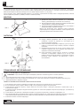
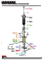
PART LIST / LISTA DE RECAMBIOS / PIÈCES DE RECHANGE /
TEILELISTE / PEÇAS DE REPOSIÇÃO / ПЕРЕЧЕНЬ ДЕТАЛЕЙ
PART LIST / LISTA DE RECAMBIOS / PIÈCES DE RECHANGE /
TEILELISTE / PEÇAS DE REPOSIÇÃO / ПЕРЕЧЕНЬ ДЕТАЛЕЙ
EN ES FR DE PT RU
BP7001.D
Kit Nº
715950
715953
Kit Nº
715951
Kit Nº
Kit Nº
715952
815409
Kit Nº
715955
Kit Nº
715956
Kit Nº
Kit Nº
715954
715208
Part Nº
815300
Part Nº
815301
Part Nº
Kit Nº
715957
For / para: 157000
Part Nº
140200
140400
Part Nº
For / para: 157004
121020
Part Nº
1
2
4
10
11
12
13
6
7
9
14
15
16
26
27
19
20
21
22
23
29
32
31
33
25
24
30
3
28
5
8
1817
REPLACEMENT KITS / KITS DE RECAMBIO
Part nº / Cód
Samoa Industrial, S.A.
P.O. Box 103 E-33200 Gijón (Asturias) Spain www.samoaindustrial.com
1/2
PEDAL ACTION GREASE PUMP
BOMBA DE ENGRASE A PEDAL
157000 157004
BP7001.D
29/05/2023

15
R. 06/23 815 804
SAMOA Industrial, S.A. · Pol. Ind. Porceyo, I-14 · Camino del Fontán, 831 · 33392 - Gijón - Spain · Tel.: +34 985 381 488 · www.samoaindustrial.com
2023_06_19-11:30
PART LIST / LISTA DE RECAMBIOS / PIÈCES DE RECHANGE /
EN ES FR
BP7001.D
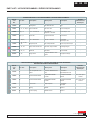
PARTS AVAILABLE SEPARATELY / PIEZAS DISPONIBLES POR SEPARADO /
PIÈCES DISPONIBLES SÉPARÉMENT
Part No.
Cód.
Réf.
Incl. Pos. Description Descripción Description
Remarks
Observaciones
Remarques
121020 17 BH-102 Hydraulic Con-
nector
Conector Hidráulico BH-
102
Connecteur
Hydraulique BH-102
140200 18 F-2000 Flexible Outlet Acoplamiento Flexible
F-2000
Accouplement exible
F-2000
For / para /pour:
157000
140400 18 F-4000 Flexible Outlet Acoplamiento Flexible
F-2000
Accouplement exible
F-4000
For / para /pour:
157004
715208 3 Tank Cover Tapa Depósito Couverture
de Dépôt -
815300 5 Spring Muelle Ressort -
815301 26 Torsion Spring Muelle Torsión Ressort -
SPARE PARTS KITS / KITS DE RECAMBIO / KITS DE REMPLACEMENT
Part No.
Cód.
Réf.
Incl. Pos. Description Descripción Description
Remarks
Observaciones
Remarques
715950 1, 2 Pulling Rod Kit Varilla De Tiro Tige -
715951 10, 11, 12, 2x(13) One Handle Kit Kit de un Asa Kit d’une Poignée -
715952 3x(9), 14 Tank + Screws Kit Kit Conjunto
Depósito + Tornillos Kit du Dépôt + Vis -
715953 5, 6, 7, 8 Piston Kit Conjunto Émbolo Kit du Piston -
715954 22, 3x(23) Foot + Screws Kit Kit Pie + Tornillos Kit du Pied
du Pumpe + Vis -
715955 17, 18, 19, 20,
24, 25 Body Pump Kit Kit Cuerpo Bomba Kit du Corps du Pumpe -
715956 21, 27, 28 Gear, Shaft and Pin Kit Kit Piñón, Eje, Pasador Kit d'Engrenages -
715957 29, 30, 31 Pedal Kit Kit Pedal Kit du Pédale -
815409 15, 16 Purge Valve Conjunto Válvula + Pur-
gador Soupape de Purge -

16 815 804 R. 06/23
SAMOA Industrial, S.A. · Pol. Ind. Porceyo, I-14 · Camino del Fontán, 831 · 33392 - Gijón - Spain · Tel.: +34 985 381 488 · www.samoaindustrial.com
2023_06_19-11:30
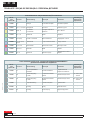
TEILELISTE / PEÇAS DE REPOSIÇÃO / ПЕРЕЧЕНЬ ДЕТАЛЕЙ
DE PT RU
BP7001.D
TEILE SEPARAT ERHÄLTLICH / PEÇAS DISPONÍVEIS SEPARADAMENTE /
ДЕТАЛИ ПОСТАВЛЯЮТСЯ ОТДЕЛЬНО
Art. Nr.
Cód.
Деталь №
Incl. Pos. Beschreibung Descrição Описание
Bemerkungen
Observações
Примечания
121020 17 BH-102 Hydraulischer
Anschluss Conector Hidráulico Гидравлический
соединитель BH-102
140200 18 Flexible Kupplung
F-2000
Acoplamento Flexível
F-2000 Гибкий выход F-2000 Für / Para / Для:
157000
140400 18 Flexible Kupplung
F-4000
Acoplamento Flexível
F-4000 Гибкий выход F-4000 Für / Para / Для:
157004
715208 3 Depot Abdeckung Cobertura Depósito Крышка бака -
815300 5Frühling Spring Большая весна -
815301 26 Frühling Torsion Spring Пружина кручения -
AUSTAUSCHKITS / PEÇAS DE REPOSIÇÃO/ ЗАПЧАСТИ
Art. Nr.
Cód.
Деталь №
Incl. Pos. Beschreibung Descrição Описание
Bemerkungen
Observações
Примечания
715950 1, 2 Strange kit de haste de tração Тяговый стержень -
715951 10, 11, 12, 2x(13) Handgriff Kit sem mãos Комплект ручек -
715952 3x(9), 14 Einsatzsatz
+ Schrauben
Montagem Depósito e
Parafusos Бак + Винты -
715953 5, 6, 7, 8 Kolben Kit Pistão Поршень -
715954 22, 3x(23) Fuß Kit + Schraube Base e Parafusos Поддержка + винты -
715955 17, 18, 19, 20,
24, 25 Gehäuse Kit Corpo central da bomba Корпус насоса -
715956 21, 27, 28 Zahnradsatz Pinhão, Eixo e Pino Шестерня и вал -
715957 29, 30, 31 Pedal Kit Pedal Педаль -
815409 15, 16 Spülventil Válvula de purga Продувочный клапан +
сборка -

17
R. 06/23 815 804
SAMOA Industrial, S.A. · Pol. Ind. Porceyo, I-14 · Camino del Fontán, 831 · 33392 - Gijón - Spain · Tel.: +34 985 381 488 · www.samoaindustrial.com
2023_06_19-11:30
NOTES / NOTAS / NOTES / NOTIZEN / NOTAS / ПРИМЕЧАНИЕ

18 815 804 R. 06/23
SAMOA Industrial, S.A. · Pol. Ind. Porceyo, I-14 · Camino del Fontán, 831 · 33392 - Gijón - Spain · Tel.: +34 985 381 488 · www.samoaindustrial.com
2023_06_19-11:30
NOTES / NOTAS / NOTES / NOTIZEN / NOTAS / ПРИМЕЧАНИЕ

19
R. 06/23 815 804
SAMOA Industrial, S.A. · Pol. Ind. Porceyo, I-14 · Camino del Fontán, 831 · 33392 - Gijón - Spain · Tel.: +34 985 381 488 · www.samoaindustrial.com
2023_06_19-11:30
NOTES / NOTAS / NOTES / NOTIZEN / NOTAS / ПРИМЕЧАНИЕ

20 815 804 R. 06/23
SAMOA Industrial, S.A. · Pol. Ind. Porceyo, I-14 · Camino del Fontán, 831 · 33392 - Gijón - Spain · Tel.: +34 985 381 488 · www.samoaindustrial.com
2023_06_19-11:30
Сертификат соответствия:
№ ТС RU С-ES.АБ58.В.01564/20, срок действия с 14.08.2020 по
13.08.2025, выдан органом по сертификации продукции «М-ФОНД»
ООО «Агентство по экспертизе и испытаниям продукции»; Адрес
125167, Россия, г. Москва, ул. Викторенко, дом 16, стр. 1. Телефон:
№RA. RU.11АБ58 от 07.04.2016 года.
Дата производства указана на маркировке изделия
Транспортировка
Изделие должно транспортироваться в заводской упаковке для
защиты от повреждений и влаги.
Хранение
Изделие должно храниться запакованным, в хорошо
проветриваемом и сухом помещении.
Утилизация
Выполняйте национальные правила утилизации и переработки
отслужившего оборудования, упаковки и принадлежностей.
RU
-
 1
1
-
 2
2
-
 3
3
-
 4
4
-
 5
5
-
 6
6
-
 7
7
-
 8
8
-
 9
9
-
 10
10
-
 11
11
-
 12
12
-
 13
13
-
 14
14
-
 15
15
-
 16
16
-
 17
17
-
 18
18
-
 19
19
-
 20
20


en otros idiomas
- français: Samoa 157000
- português: Samoa 157000
Artículos relacionados
-
Samoa 531430 Instructions Manual
-
-
-
-
-
-
-
-
-