
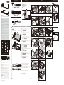
User Manual
Product Code:
A-ITX51-A1B / A-ITX51-M1B & A-ITX52-A1B / A-ITX52-M1B
Power switch
Power LED
Hard drive LED
Mobile tray
USB 2.0 port
USB 3.2 port
Installation VESA Mounting Instructions
2022/04
Internal Layout
❶ CPU thermal module
❷ front panel PCB
❸ M/B mounting standoffs
❹ heatpipes
❺ mobile tray
❻ riser cable mounting standoffs
Internal Cable Connectors
GB
Connect the case internal cable connectors to the corresponding motherboard headers.
NOTE : If the connectors are not apparent on the board consult your motherboard
manual. Connecting the panel to the wrong headers may result in motherboard
damage.
FR
Branchez les connecteurs de câble internes du boîtier aux embases de carte mère
correspondantes.
REMARQUE : Si les connecteurs ne sont pas apparents sur la carte, consultez le manuel
de votre carte mère. Si vous connectez le panneau aux mauvaises embases cela risque
d’endommager la carte mère.
D
Schließen Sie die Gehäuseinternen Kabel-Anschlüsse an die entsprechenden
Motherboard-Anschlüße.
HINWEIS: Wenn die Anschlüsse auf dem Motherboard nicht ersichtlich sind, schauen
Sie bitte in ihren Motherboard-Handbuch nach. Ein Anschluss des Panels an die falschen
Anschlüße kann dazu führen, dass das Motherboard beschädigt wird.
ES
Conecte los conectores de los cables del interior de la carcasa en los correspondientes
cabezales de la placa base.
NOTA: Si los conectores no aparecen en la placa, consulte el manual de la placa base La
conexión del panel en los cabezales equivocados podría dañar la placa base.
PT
Conecte os cabos internos do gabinete, nas entradas correspondentes da placa-mãe.
NOTA : No caso das entradas não estarem marcadas na placa-mãe, consulte o manual
da mesma. Conectar os cabos numa entrada errada, pode danificar a placa-mãe.
RU
Подключите разъемы внутренних кабелей корпуса к соответствующим разъемам
материнской платы.
ПРИМЕЧАНИЕ: Если вы не видите этих разъемов на плате, обратитесь к руководству
пользователя системной платы.
Подключение панели к неверным разъемам может привести к повреждению системной
платы.
JP
CN
根据圖示說明,將机箱線材插在相對應的端子上。
注意: 如果在主板上沒看到相對應的端子,請參考主板之使用說明.如果線材接錯,有可能
造成主板損坏。
POWER LED+
POWER LED-
Power LED
connectors
H.D.D LED
HDD
activity LED
USB 3.2
connector
POWER SW
2-pin Power
Switch
connector
GB
CAUTION
Electrostatic discharge (ESD) can damage system components. If an ESD-controlled workstation is not available, wear an antistatic wrist
strap or touch an earthed surface before handling any PC components.
WARNING
Please be careful when unpacking and setting up this product as metal edges can cause injury if not handled with care. Keep away from
children.
FR
ATTENTION
Une décharge électrostatique (ESD) risque d’endommager les composants du système. Si vous ne disposez pas d’une station de travail avec
protection contre l’ESD, portez un bracelet antistatique ou touchez une surface reliée à la terre avant de manipuler les composants de
l’ordinateur.
AVERTISSEMENT
Faites attention lors du déballage et de l’installation de ce produit car il comporte des coins métalliques coupants qui risquent de vous
blesser s’ils ne sont pas manipulés avec soin.
Garder loin des enfants.
D
Vorsicht:
Elektrostatische Entladungen (ESD – Electrostatic discharge) können Systemkomponenten beschädigen. Sollte ein ESD geschützter
Arbeitsplatz nicht vorhanden sein, tragen Sie ein antistatisches Armband oder berühren Sie eine geerdete Oberfläche bevor Sie mit den
Arbeiten am Computer beginnen.
Warnung
Seien Sie vorsichtig beim Auspacken und beim Aufbau dieses Produktes. Scharfe Metallkanten könnten Verletzungen hervorrufen wenn
ohne die nötige Vorsicht vorgegangen wird.
Von Kindern fernhalten.
ES
CUIDADO
Descargas electrostáticas (ESD) pueden dañar los componentes de su sistema. Si no puede disponer de una estación de trabajo libre de
electrostática, use una muñequera antiestática o toque una superficie que haga tierra antes de manipular los componentes del ordenador.
PELIGRO
Por favor sea cuidadoso cuando desempaquete y ensamble este producto. Los filos de metal pueden causarle cortes o heridas si no son
manipulados adecuadamente.
Aléjate de los niños.
PT
CUIDADO
Descargas Eletroestáticas (ESD) podem danificar componentes do PC. Caso não tenha uma bancada específica disponível, utilize uma
pulseira anti-estática ou toque uma superfície aterrada antes de manusear qualquer componente.
ATENÇÃO
Por favor tenha cuidado ao desembrulhar e montar este produto, as extremidades de metal podem machucar, caso o mesmo não seja
manuseado com cuidado.
Manter fora do alcance das crianças.
RU
ОСТОРОЖНО
Электростатический разряд (ЭСР) может повредить компоненты системы. Если рабочее место с защитой от ЭСР отсутствует,
рекомендуется при работе с компьютерными компонентами надевать антистатический браслет или обеспечить контакт тела с
заземленной поверхностью.
ОПАСНО
Соблюдайте осторожность при распаковке и монтаже этого изделия так как острые края металлических частей могут стать причиной
физической травмы. Не подпускайте к изделию детей.
JP
CN
注意
靜電放電(ESD)可能會損壞系統元件。請使用低ESD工作站。若無法取得此類工作站,請先穿戴防靜電脘帶或碰觸地表面,再拿取任何
電腦組件。
警告
開箱及安裝中請小心取用,避免被金属邊緣割傷。遠離孩童。
USB 2.0
connector
❶
❷
GB
Ensure the installation follows the illustrated instructions for screw removal and
tightening to prevent mis-alignment of the panels.
unfasten screws: ❶�❷�❸�❹
tighten screws: ❹�❸�❷�❶
FR
Assurez-vous l'installation respecte les instructions telles qu'illustrées.
Si les étapes ne sont pas suivies correctement pour le retrait et le serrage des vis,
celles-ci risquent d'être endommagées.
Retrait des vis : ❶�❷�❸�❹
screw lock: ❹�❸�❷�❶
D
Stellen Sie sicher, dass die Installation gemäß der Abbildung verläuft. Falsche
Schritte beim Entfernen und Befestigen der Schrauben werden zu einem Versagen
der Schrauben führen.
Schraube entfernen: ❶�❷�❸�❹
Schraube befestigen: ❹�❸�❷�❶
ES
Asegúrese seguir las instrucciones ilustradas para la instalación.
Si sigue los pasos para quitar los tornillos de manera incorrecta podría dañarlos.
quitar tornillo: ❶�❷�❸�❹
bloquear tornillo: ❹�❸�❷�❶
PT
Certifique-se da instalação de acordo com a sequência das ilustrações.
A Sequência incorreta na remoção e/ou aperto dos parafusos, podem danificar o
parafuso.
Remoção dos parafusos: ❶�❷�❸�❹
Fixação dos parafusos: ❹�❸�❷�❶
RU
Выполните монтаж, следуя указаниям на рисунке.
Неправильный порядок отвинчивания и затягивания винтов может привести к
повреждению винтов.
Отвинчивание винтов: ❶�❷�❸�❹
Затягивание винтов: ❹�❸�❷�❶
JP
ねじの取り外し: ❶�❷�❸�❹
ねじの固定: ❹�❸�❷�❶
CN
務必確認安裝步驟如圖所示。
不正確的卸除螺絲及安裝螺絲順序可能造成螺絲滑牙的毀損。
卸除螺絲:❶�❷�❸�❹
鎖上螺絲:❹�❸�❷�❶
5140265801 V1
Front panel
Rear panel
❹❶
❸
❸
❸
❸❻
❻
❷
❺
17
8
9
10-1
10-2
10-3
USB 3.2 connector
USB 2.0 connector
For PCI-e card installation
PCI-e Card
⑯
❶
❷
I/O Shield
2
3
4
5
6
⑤
⑥
⑥
⑦
⑧
⑨
⑩
⑤
2.5” HDD / SDD
11
12
13
14
15
⑫
⑬
⑮
⑪
SATA power connector SATA connector
1U Rackmount Front Panel
⑯
for A-ITX51
for A-ITX52
Power switch
Power LED
Hard drive LED
Mobile tray
USB 2.0 port
USB 3.2 port
Do not remove the screws indicated in the illustration.
Ne retirez pas les vis indiquées dans l'illustration.
Entfernen Sie nicht die in der Abbildung gezeigten Schrauben.
No quite los tornillos indicados en la illustración.
Não remova os parafusos indicados na ilustração.
Не вынимайте винты, показанные на рисунке.
。
請勿拆除圖中所示的螺絲。
GB
FR
D
PT
ES
RU
JP
CN
Contents
① ②
x4 x4 Retention plate for
LGA 115X/1200
④
⑤
x7
Retention plate for
LGA1700
CPU thermal module for
LGA 115X/1200/1700
③
⑥ ⑦ ⑨⑧
x4x2x2
x4
⑭
x2 x2x14
⑪ ⑫ ⑬
⑩
x1
x1
⑮
x4
⑯
x4
⑱
⑰
x6 Case feet
Front & rear panels
screws (spare part)
10-4
⑤
for A-ITX51
for A-ITX52
Rear Panel
Low profile
PCI-e opening
Antenna fitting hole
M/B I/O shield opening
Kensington lock opening
Antenna fitting hole
Front Panel Layout
⑪
⑭
❸
❹
①
②
③
CPU
④
LGA1700
LGA 115X/1200

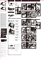
User manual
Product Code:
A-ITX53-A1B / A-ITX53-M1B & A-ITX54-A1B / A-ITX54-M1B
Power switch
Power LED
Hard drive LED
Installation VESA Mounting Instructions
2022/04
Front Panel Layout Internal layout
❶ CPU thermal module
❷ front panel PCB
❸ M/B mounting standoffs
❹ heatpipes
❺ 2.5'' SSD/HDD mounting bracket
❻ riser cable mounting standoffs
Internal Cable Connectors
GB
Connect the case internal cable connectors to the corresponding motherboard headers.
NOTE : If the connectors are not apparent on the board consult your motherboard
manual. Connecting the panel to the wrong headers may result in motherboard
damage.
FR
Branchez les connecteurs de câble internes du boîtier aux embases de carte mère
correspondantes.
REMARQUE : Si les connecteurs ne sont pas apparents sur la carte, consultez le manuel
de votre carte mère. Si vous connectez le panneau aux mauvaises embases cela risque
d’endommager la carte mère.
D
Schließen Sie die Gehäuseinternen Kabel-Anschlüsse an die entsprechenden
Motherboard-Anschlüße.
HINWEIS: Wenn die Anschlüsse auf dem Motherboard nicht ersichtlich sind, schauen
Sie bitte in ihren Motherboard-Handbuch nach. Ein Anschluss des Panels an die falschen
Anschlüße kann dazu führen, dass das Motherboard beschädigt wird.
ES
Conecte los conectores de los cables del interior de la carcasa en los correspondientes
cabezales de la placa base.
NOTA: Si los conectores no aparecen en la placa, consulte el manual de la placa base La
conexión del panel en los cabezales equivocados podría dañar la placa base.
PT
Conecte os cabos internos do gabinete, nas entradas correspondentes da placa-mãe.
NOTA : No caso das entradas não estarem marcadas na placa-mãe, consulte o manual
da mesma. Conectar os cabos numa entrada errada, pode danificar a placa-mãe.
RU
Подключите разъемы внутренних кабелей корпуса к соответствующим разъемам
материнской платы.
ПРИМЕЧАНИЕ: Если вы не видите этих разъемов на плате, обратитесь к руководству
пользователя системной платы.
Подключение панели к неверным разъемам может привести к повреждению системной
платы.
JP
CN
根据圖示說明,將机箱線材插在相對應的端子上。
注意: 如果在主板上沒看到相對應的端子,請參考主板之使用說明.如果線材接錯,有可能
造成主板損坏。
POWER LED+
POWER LED-
Power LED
connectors
H.D.D LED
HDD
activity LED
USB 3.2
connector
POWER SW
2-pin Power
Switch
connector
GB
CAUTION
Electrostatic discharge (ESD) can damage system components. If an ESD-controlled workstation is not available, wear an antistatic wrist
strap or touch an earthed surface before handling any PC components.
WARNING
Please be careful when unpacking and setting up this product as metal edges can cause injury if not handled with care. Keep away from
children.
FR
ATTENTION
Une décharge électrostatique (ESD) risque d’endommager les composants du système. Si vous ne disposez pas d’une station de travail avec
protection contre l’ESD, portez un bracelet antistatique ou touchez une surface reliée à la terre avant de manipuler les composants de
l’ordinateur.
AVERTISSEMENT
Faites attention lors du déballage et de l’installation de ce produit car il comporte des coins métalliques coupants qui risquent de vous
blesser s’ils ne sont pas manipulés avec soin.
Garder loin des enfants.
D
Vorsicht:
Elektrostatische Entladungen (ESD – Electrostatic discharge) können Systemkomponenten beschädigen. Sollte ein ESD geschützter
Arbeitsplatz nicht vorhanden sein, tragen Sie ein antistatisches Armband oder berühren Sie eine geerdete Oberfläche bevor Sie mit den
Arbeiten am Computer beginnen.
Warnung
Seien Sie vorsichtig beim Auspacken und beim Aufbau dieses Produktes. Scharfe Metallkanten könnten Verletzungen hervorrufen wenn
ohne die nötige Vorsicht vorgegangen wird.
Von Kindern fernhalten.
ES
CUIDADO
Descargas electrostáticas (ESD) pueden dañar los componentes de su sistema. Si no puede disponer de una estación de trabajo libre de
electrostática, use una muñequera antiestática o toque una superficie que haga tierra antes de manipular los componentes del ordenador.
PELIGRO
Por favor sea cuidadoso cuando desempaquete y ensamble este producto. Los filos de metal pueden causarle cortes o heridas si no son
manipulados adecuadamente.
Aléjate de los niños.
PT
CUIDADO
Descargas Eletroestáticas (ESD) podem danificar componentes do PC. Caso não tenha uma bancada específica disponível, utilize uma
pulseira anti-estática ou toque uma superfície aterrada antes de manusear qualquer componente.
ATENÇÃO
Por favor tenha cuidado ao desembrulhar e montar este produto, as extremidades de metal podem machucar, caso o mesmo não seja
manuseado com cuidado.
Manter fora do alcance das crianças.
RU
ОСТОРОЖНО
Электростатический разряд (ЭСР) может повредить компоненты системы. Если рабочее место с защитой от ЭСР отсутствует,
рекомендуется при работе с компьютерными компонентами надевать антистатический браслет или обеспечить контакт тела с
заземленной поверхностью.
ОПАСНО
Соблюдайте осторожность при распаковке и монтаже этого изделия так как острые края металлических частей могут стать причиной
физической травмы. Не подпускайте к изделию детей.
JP
CN
注意
靜電放電(ESD)可能會損壞系統元件。請使用低ESD工作站。若無法取得此類工作站,請先穿戴防靜電脘帶或碰觸地表面,再拿取任何
電腦組件。
警告
開箱及安裝中請小心取用,避免被金属邊緣割傷。遠離孩童。
USB 2.0
connector
GB
Ensure the installation follows the illustrated instructions for screw removal and
tightening to prevent mis-alignment of the panels.
unfasten screws: ❶�❷�❸�❹
tighten screws: ❹�❸�❷�❶
FR
Assurez-vous l'installation respecte les instructions telles qu'illustrées.
Si les étapes ne sont pas suivies correctement pour le retrait et le serrage des vis,
celles-ci risquent d'être endommagées.
Retrait des vis : ❶�❷�❸�❹
screw lock: ❹�❸�❷�❶
D
Stellen Sie sicher, dass die Installation gemäß der Abbildung verläuft. Falsche
Schritte beim Entfernen und Befestigen der Schrauben werden zu einem Versagen
der Schrauben führen.
Schraube entfernen: ❶�❷�❸�❹
Schraube befestigen: ❹�❸�❷�❶
ES
Asegúrese seguir las instrucciones ilustradas para la instalación.
Si sigue los pasos para quitar los tornillos de manera incorrecta podría dañarlos.
quitar tornillo: ❶�❷�❸�❹
bloquear tornillo: ❹�❸�❷�❶
PT
Certifique-se da instalação de acordo com a sequência das ilustrações.
A Sequência incorreta na remoção e/ou aperto dos parafusos, podem danificar o
parafuso.
Remoção dos parafusos: ❶�❷�❸�❹
Fixação dos parafusos: ❹�❸�❷�❶
RU
Выполните монтаж, следуя указаниям на рисунке.
Неправильный порядок отвинчивания и затягивания винтов может привести к
повреждению винтов.
Отвинчивание винтов: ❶�❷�❸�❹
Затягивание винтов: ❹�❸�❷�❶
JP
ねじの取り外し: ❶�❷�❸�❹
ねじの固定: ❹�❸�❷�❶
CN
務必確認安裝步驟如圖所示。
不正確的卸除螺絲及安裝螺絲順序可能造成螺絲滑牙的毀損。
卸除螺絲:❶�❷�❸�❹
鎖上螺絲:❹�❸�❷�❶
2.5” HDD / SDD
5140265801 V1
Front panel
Rear panel
1 7 10-4
8 11
9 12
10-1 13
10-2 14
10-3 15
USB 3.2 connector
USB 2.0 connector
For PCI-e card installation
PCI-e Card
⑤ ⑯
⑪ ⑫
⑬
⑭
⑮
⑪
SATA power connector SATA connector
❶
❷
⑩
⑤
1U Rackmount Front Panel
for A-ITX53
for A-ITX54
Do not remove the screws indicated in the illustration.
Ne retirez pas les vis indiquées dans l'illustration.
Entfernen Sie nicht die in der Abbildung gezeigten Schrauben.
No quite los tornillos indicados en la illustración.
Não remova os parafusos indicados na ilustração.
Не вынимайте винты, показанные на рисунке.
。
請勿拆除圖中所示的螺絲。
GB
FR
D
PT
ES
RU
JP
CN
USB 2.0 port
USB 3.2 port
Power switch
Power LED
Hard drive LED
USB 2.0 port
USB 3.2 port
❹❶
❸
❸
❸
❸
❷
❺
⑯
Contents
① ②
x4 x4
④
⑤
x7
③
⑥ ⑦ ⑨⑧
x4x2x2
x4
⑭
x2 x2x14
⑪ ⑫ ⑬
⑩
x1
x1
⑮
x4
⑯⑰
x6 x4
⑱
x4
Case feet
Front & rear panels
screws (spare part)
①
②
③
CPU
④
LGA1700
LGA 115X/1200
for A-ITX53
for A-ITX54
Retention plate for
LGA 115X/1200
Retention plate for
LGA1700
CPU thermal module for
LGA 115X/1200/1700
Rear Panel
Low profile
PCI-e opening
Antenna fitting hole
M/B I/O shield opening
Kensington lock opening
Antenna fitting hole
❻
❻
❶
❷
❸
❹
I/O Shield
2
3
4
5
6
⑤
⑥
⑥
⑦
⑧
⑨
-
 1
1
-
 2
2


en otros idiomas
- français: Akasa A-ITX51-A1B Manuel utilisateur
- português: Akasa A-ITX51-A1B Manual do usuário
- 日本語: Akasa A-ITX51-A1B ユーザーマニュアル
Artículos relacionados
-
Akasa AK-CC4021HP01 Manual de usuario
-
Akasa A-NUC63-A1B Manual de usuario
-
Akasa A-ITX48-A1B Manual de usuario
-
-
Akasa Euler Manual de usuario
-
-
-
-
-
