Notas importantes para el instalador
1. Leatodas lasinstruccionescontenidas en este manual
antes de instalarel combinacion microondas/ homo de
pared.
2. Saquetodo el material usado enel embalaje del
compartimiento del homo antes de conectar el suministro
electrico o de gasa la estufa.
3. Observetodos loscodigos y reglamentos pertinentes.
4. Dejeestasinstrucciones con el consumidor.
5. Lapuerta del homo se puede retirar para facilitar la
instalacion.
6. ESTECOMBINACION MICROONDAS / HORNO DE
PAREDNO ESTAAPROBADO PARA LA INSTALACION
APILABLE O DE LADO A LADO,
Nota importante ai consumidor
Conserve estas instrucciones y el manual del usuario para
referencia futura. No tirar las herramientas para retirar el
homo incluidas en la bolsa de la literatura.
INSTRUCCIONES
IMPORTANTES DE SEGURIDAD
• Asegurese de que su combinacion microondas /
homo de pared sea instalado y puesto a tierra de
forma apropiada pot un instalador calificado o pot
un tecnico de servicio,
• Este homo de pared debe set electricarnente puesto
a tierra de acuerdo con los c6digos locales o, en su
ausencia, con el C6digo Electrico National ANSi/
NFPA No. 70-ultirna edici6n en los Estados Unidos, o
el C6digo Electrico Canadiense CSA Standard C22,1,
Part 1, en Canada,
Pisar, apoyarse, o sentarse sobre la
puerta de este homo de pared puede causar serias
lesiones y da_os al homo de pared,
• Nunca use su homo de pared para calentar una
habitation. El uso prolongado de la estufa sin la
ventilacion adecuada puede set peligroso.
La corriente electrica al homo debe
estar apagada rnientras se hacen las conexiones
de lineas. Si no se apaga, da_os serios o la rnuerte
podrian resultar,
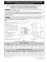
1. Carpinteria
Consulte la Figura 1 para conocer lasdimensiones pertinentes
al modelo de su homo y al espacio necesarioen el que poner
el homo. Lasuperficie donde seva a apoyar el homo debe
de set de madera contrachapada solida u otto material similar
y,sobre todo, la superficie tiene que estar a nivel, de lado a
lado, y de atr_ishaciaadelante.
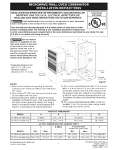
2. Requerirnientos Electricos
Se debe proveer el voltaje y la frecuencia apropiados a
este electrodom_stico, y conectarse a un circuito individual
correctamente puesto a tierra, protegido por un interruptor o
un fusible. Paraconocer el interruptor o fusible que requiere
su modelo, vea la placa serial para encontrar la consumaci0n
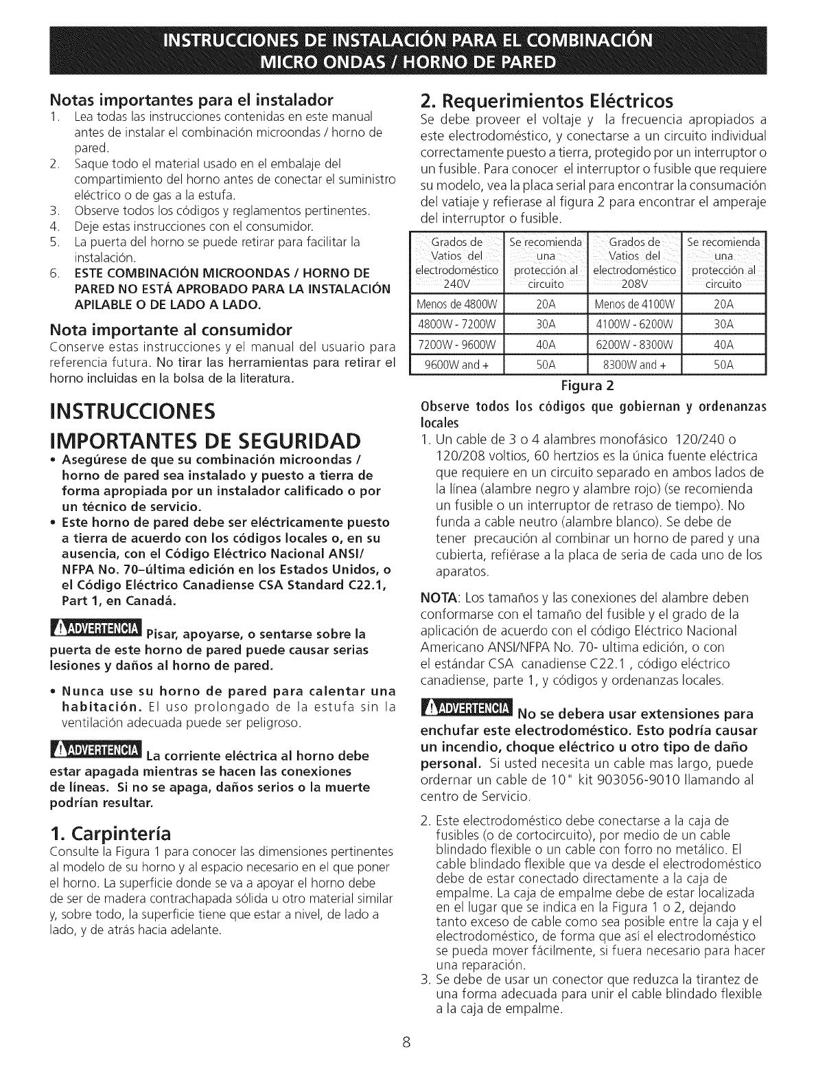
del vatiaje y refierase al figura 2 para encontrar el amperaje
del interruptor o fusible.
Grados de " ' ' "
Se recomlenda Grados de Se recomlenda
Vatios del una Vatios del Una
electrodom_stico iorotea:i6n a! electrodom_stico protecd6n a!
240V circuito 208V- circuito
Menosde4800W 20A Menosde4100W 20A
4800W-7200W 30A 4100W-6200W 30A
7200W-g600W 40A 6200W-8300W 40A
g600Wand+ 50A 8300Wand+ 50A
Figura 2
Observe todos los c6digos que gobiernan y ordenanzas
locales
1. Un cable de 3 o 4 alambres monof_isico 120/240 o
120/208 voltios, 60 hertzios es la Onicafuente el6ctrica
que requiere en un circuito separado en ambos lados de
la linea (alambre negro y alambre rojo) (serecomienda
un fusible o un interruptor de retraso de tiempo). No
funda a cable neutro (alambre blanco). Se debe de
tener precauci6n al combinar un homo de pared y una
cubierta, refi6rase a la placa de seria de cada uno de los
aparatos.
NOTA: Lostamahos y las conexiones del alambre deben
conformarse con el tamaho del fusible y el grado de la
aplicaci6n de acuerdo con el c6digo El#ctrico Nacional
Americano ANSI/NFPANo. 70- ultima edici6n, o con
el est_indarCSA canadiense C22.1 , c6digo el#ctrico
canadiense, parte 1, y c6digos y ordenanzas locales.
No se debera usar extensiones para
enchufar este electrodomestico, Esto podria causar
un incendio, choque electrico u otto tipo de daffo
personal, Si usted necesita un cable mas largo, puede
ordernar un cable de 10" kit 903056-9010 Ilamando al
centro de Servicio.
2. Esteelectrodom#stico debe conectarse a la caja de
fusibles (o de cortocircuito), por medio de un cable
blindado flexible o un cable con forro no met_ilico. El
cable blindado flexible que va desde el electrodom_stico
debe de estar conectado directamente a la caja de
empalme. La caja de empalme debe de estar Iocalizada
en el lugar que se indica en la Figura 1 o 2, dejando
tanto exceso de cable como sea posible entre la caja y el
electrodom_stico, de forma que asiel electrodom_stico
se pueda mover flicilmente, si fuera necesario para hacer
una reparaciOn.
3. Se debe de usar un conector que reduzca la tirantez de
una forma adecuada para unir el cable blindado flexible
a la caja de empalme.
8