Westinghouse 7800100 Guía de instalación
- Categoría
- Ventiladores domésticos
- Tipo
- Guía de instalación

4 5
ETL-ES-Delancey-WH14 ETL-ES-Delancey-WH14
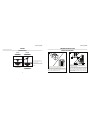
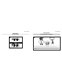
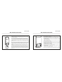
Note: For pitched ceiling installation, please
refer to westinghouselighting.com for specially
designed canopy kit options.
Nota: Para instalación en cielo rasos inclinados,
visite westinghouselighting.com para obtener
información.
FEATURES
CARACTERÍSTICAS
For normal ceilings
Para cielorrasos normales
VAULTED CEILING
INSTALLATION
NSTALACIÓN PARA
CIELORRASOS ABOVEDADOS
DOWNROD
INSTALLATION
INSTALACIÓN CON
VARILLA VERTICAL
May require a longer downrod
(sold separately)
Podría requerir una varilla vertical más larga
(se vende por separado)
Unpack and inspect fan carefully to be certain all contents are included.
Turn off power at fuse box to avoid possible electrical shock.
1
Use metal outlet box suitable for fan support (must support 35 lbs).
Before attaching fan to outlet box, ensure the outlet box is securely
fastened by at least two points to a structural ceiling member (a loose
box will cause the fan to wobble).
2
PREPARING FOR INSTALLATION
ANTES DE LA INSTALACIÓN
Quite el envoltorio e inspeccione detenidamente el ventilador para verificar
que todas las piezas estén incluidas. Apague la alimentación en la caja de
fusibles para evitar la posibilidad de descarga eléctrica.
Use una caja de embutir de metal adecuada para soportar un ventilador
(debe soportar 35 libras). Antes de fijar el ventilador a la caja de embutir
asegúrese de que la misma esté fijada de manera segura en por lo menos
dos puntos a un miembro estructural del cielo raso (una caja suelta haría
que el ventilador oscile).

6 7
ETL-ES-Delancey-WH14 ETL-ES-Delancey-WH14
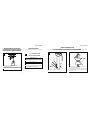
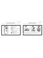
Instale el soporte de montaje a la caja de embutir del cielorraso con la
tornillería suministrada con la caja de embutir.
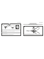
MOUNTING BRACKET INSTALLATION
INSTALACIÓN CON SOPORTE DE MONTAJE
3
4
MOUNTING OPTIONS
OPCIONES DE MONTAJE
Choose a MOUNTING OPTION
Elija una OPCIÓN DE MONTAJE
NORMAL DOWNROD OPTION
If installing downrod supplied with fan, proceed to page 7, step#5.
OPCIÓN CON VARILLA VERTICAL PARA CIELORRASO NORMAL
Si instala la varilla vertical incluida con el ventilador,
proceda a la página 7, paso 5.
EXTENDED DOWNROD OPTION
If installing with longer downrod than supplied with fan, proceed to page 9, step#8.
OPCIÓN CON VARILLA VERTICAL MÁS LARGA
Si instala una varilla vertical más larga que la que se incluye con el
ventilador, proceda a la página 9, paso 8.
Install mounting bracket to outlet box in ceiling using the screws and
washers provided with the outlet box.
6
Place downrod assembly into canopy (1), canopy cover ring (2) and coupling cover (3).
Feed motor wires through the downrod assembly (4).
Coloque el conjunto de la varilla vertical (1) dentro del dosel (1), el anillo de la cubierta
del dosel (2) y la cubierta del acoplamiento (3). Pase los cables del motor a través del
conjunto de la varilla vertical (4).
2
1
3
4
Quite el pasador tipo prensa (1) desde el pasador transversal (2) de la vara (3).
5
Remove clamp pin (1) and cross pin (2) from downrod (3).
1
2
3
NORMAL DOWNROD OPTION
OPCIÓN CON VARILLA VERTICAL PARA CIELORRASO NORMAL

8 9
ETL-ES-Delancey-WH14 ETL-ES-Delancey-WH14
NORMAL DOWNROD OPTION
OPCIÓN CON VARILLA VERTICAL PARA CIELORRASO NORMAL
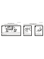
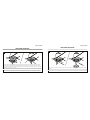
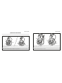
Loosen set screws (1) in downrod coupling (2). Insert downrod into downrod coupling. Make sure to align hole in downrod with the hole in downrod coupling. Install cross pin (4) through
coupling and downrod. Insert keeper pin (5) into cross pin until it snaps into place. Tighten set screws (1) in coupling. Slide coupling cover (3) over the downrod coupling. PROCEED TO
PAGE 11, STEP#12.
Afloje los tornillos prisioneros (1) en el acoplador (2). Inserte la varilla vertical en el acoplamiento de la varilla vertical. Asegúrese de que el orificio de la varilla vertical y el del acoplamiento
de la varilla vertical estén alineados. Instale el pasador transversal (4) pasándolo por el acoplamiento y la varilla vertical. Inserte el pasador de fijación (5) en el pasador transversal hasta que
escuche un chasquido que indique que está en la posición adecuada. Ajuste los tornillos de fijación (1) en el acoplamiento. Deslice la cubierta del acoplamiento (3) sobre el acoplamiento de
la varilla vertical. PASEZ À LA PAGE 11, ÉTA PE 12.
7
4
2
3
1
5
Loosen downrod ball (1) from downrod (2) by removing set screw (3).
Afloje la esfera de la varilla vertical (1) de la varilla vertical (2)
quitando el tornillo (3).
8
2
3
1
EXTENDED DOWNROD OPTION
OPCIÓN CON VARILLA VERTICAL MÁS LARGA
Slide downrod ball (1) off of downrod and remove pin (2).
Deslice la esfera de la varilla vertical (1) hasta separarla de la
varilla vertical y quite el pasador (2).
9
2
1

10 11
ETL-ES-Delancey-WH14 ETL-ES-Delancey-WH14
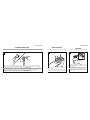
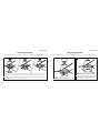
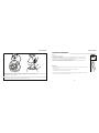
Re-install pin into extended downrod, and slide downrod ball up to the top of the downrod. Re-install set screw to secure ball to downrod. Note: Some extended downrods have
a pre-drilled set-screw hole. If a pre-drilled hole is present in the extended downrod, tighten the set screw into the pre-drilled hole in the extended downrod. If no pre-drilled hole
exists in the extended downrod, tighten the set screw against the downrod to secure the downrod ball. PROCEEDTO PAGE 7, STEP#5.
Vuelva a instalar el pasador en la varilla vertical más larga y deslice la esfera de la varilla hasta el extremo superior de la misma. Vuelva a insertar el tornillo de fijación para asegurar
la esfera a la varilla vertical. Nota: Algunas varillas verticales más largas tienen un agujero previamente perforado para el tornillo. Si la varilla vertical más larga tiene un agujero
previamente perforado, ajuste el tornillo en el agujeropreviamente perforado de la varilla vertical más larga. Si la varilla vertical más larga no tiene un agujero
previamente perforado, ajuste el tornillo sobre la varilla vertical para asegurar la esfera de la misma.
PASEZ À LA PAGE 7, ÉTA PE 5.
EXTENDED DOWNROD OPTION
OPCIÓN CON VARILLA VERTICAL MÁS LARGA
10
12
BLADE INSTALLATION
INSTALACIÓN DE LAS PALETAS
MOUNTING
MONTAJE
11
Install the 3 ABS blades onto the motor by using the motor screws provided,
tighten them securely.
Instale las 3 paletas ABS sobre el motor utilizando los tornillos para el motor
provistos; ajústelos para asegurar las paletas.
Carefully lift fan assembly onto mounting bracket. Rotate fan until notch on
downrod ball (1) engages the ridge on the mounting bracket (2). This will
allow for hands free wiring.
Levante con cuidado el conjunto del ventilador hasta el soporte de montaje.
Gire el ventilador hasta que la muesca de la bola de la varilla vertical (1)
calce sobre la saliente del soporte de montaje (2). De este modo, tendrá
las dos manos libres para hacer el cableado. incluidos. Apriete los tornillos
asegurándolos.
La página se está cargando...

14 15
ETL-ES-Delancey-WH14 ETL-ES-Delancey-WH14
15
The inside canopy cover ring (1) has two keyhole slots that allow it to be mounted onto the screw heads on the two protruding screws from the mounting bracket. Slide the canopy cover ring
up the downrod, and allow the two protruding screw heads from the mounting bracket to go into the keyhole slots on the canopy cover ring. Once engaged, twist the canopy cover ring to
lock it onto the screw heads. Note: Some adjustment of the screws from the mounting bracket may be necessary to allow the canopy cover ring to attach to the screw heads in the appropriate
manner:
1. Loosening of the screw heads may be necessary to allow the canopy cover ring to t onto the screws from the mounting bracket.
2. If the canopy is still loose after installing the canopy cover ring, the canopy cover ring may need to be removed and the mounting bracket screws tightened slightly to allow a more snug t
of the canopy, when the canopy cover ring is installed.
La cubierta interior para el anillo (1) del dosel tiene dos ranuras que permiten montarla en las cabezas de los dos tornillos que sobresalen del soporte de montaje. Deslice la cubierta el anillo
del escudete hacia arriba por la varilla y permita que las dos cabezas sobresalientes de los tornillos penetren en las ranuras de la cubierta del escudete. Una vez penentren, gire la cubierta del
escudete para trabar las cabezas de los tornillos en la parte más estrecha. Nota: Puede ser necesario ajustar los tornillos del soporte de montaje para permitir que la cubierta del escudete se
acople a las cabezas de los tornillos de manera apropiada.
1. Aoje los tornillos si es necesario para permitir que la cubierta del escudete pase sobre los tornillos del soporte de montaje.
2. Si el escudete aún está suelto después de instalar la cubierta el anillo del escudete, puede que sea necesario retirar la cubierta el anillo del escudete y apretar ligeramente los tornillos del
soporte de montaje para lograr un ajuste más preciso del escudete una vez instalada la cubierta el anillo del escudete.
1
LIGHT FIXTURE INSTALLATION
INSTALACIÓN DEL ARTEFACTO LUMINOSO
Remove one screw from the switch housing mounting plate (1) and loosen the other two.
Quite uno de los tornillos de la placa del alojamiento del interruptor (1) y afloje los otros dos.
16
1

16 17
ETL-ES-Delancey-WH14 ETL-ES-Delancey-WH14
Insert the wires from the fan through the middle hole in the metal decorative shade(1). Position both slots on the metal decorative shade directly under and in line
with the two screws in the switch housing mounting plate. Lift the metal decorative shade, allowing the two screws to slide into the mating slots. Rotate the metal
decorative shade until both screws from the switch housing mounting plate drop into the slot recesses. Install the screw removed in step#16 into the closed hole of the
metal decorative shade and tighten all 3 screws securely.
Pase los cables del ventilador a través del orificio central de la pantalla decorativa de metal (1). Coloque las dos ranuras de la pantalla decorativa de metal directamente
debajo y en alineación con los dos tornillos de la placa de montaje del alojamiento del interruptor. Eleve la pantalla decorativa de metal, permitiendo que los dos
tornillos se deslicen dentro de las ranuras. Gire la pantalla decorativa de metal hasta que ambos tornillos de la placa de montaje del alojamiento del interruptor caigan
adentro de las ranuras. Coloque el tornillo que extrajo en el paso 16 en el orificio cerrado de la pantalla decorativa de metal y apriete los 3 tornillos para asegurarlos.
17
1
LIGHT FIXTURE INSTALLATION
INSTALACIÓN DEL ARTEFACTO LUMINOSO
!
LIGHT FIXTURE INSTALLATION
INSTALACIÓN DEL ARTEFACTO LUMINOSO
Remove one of the 3 screws on the metal decorative shade (1), and loosen, (do not remove) the other two. Find the wire plugs from the light kit and from the motor and
slide together.
Extraiga uno de los 3 tornillos de la pantalla decorativa de metal (1) y afloje los otros dos (sin sacarlos del todo). Identifique los conectores para cables de salida del
artefacto luminoso y del motor y deslícelos para unirlos.
18
1

18 19
ETL-ES-Delancey-WH14 ETL-ES-Delancey-WH14
LIGHT FIXTURE INSTALLATION
INSTALACIÓN DEL ARTEFACTO LUMINOSO
The light kit has 2 keyhole slots. Align the slots on the light kit to the protruding screws from the light kit support plate (1). Raise the light kit allowing the protruding
screws from the support plate to enter the keyhole slots on the light kit. Rotate the light kit clockwise to engage the slots, and tighte screws to secure the light kit.
El juego de luces tiene 2 ranuras bocallaves. Alinee las ranuras del juego de luces con los tornillos que sobresalen de la placa de soporte (1) del juego de luces. Levante el
juego de luces permitiendo que los tornillos que sobresalen de la placa de soporte entren en las ranuras bocallaves del juego de luces. Gire el juego de luces en sentido
horario para que enganche en las ranuras y ajuste los tornillos para asegurar el juego de luces.
19
LIGHT FIXTURE INSTALLATION
INSTALACIÓN DEL ARTEFACTO LUMINOSO
20 22
Install light bulbs (13 watt max, included).
Instale las lámparas (13 vatios como máx, incluidas).
Locate the indentations on the neck of the glass and align with the protrusions on
the inside of the light kit. Lift the glass up allowing the protrusions to engage the
indentations of the glass, and twist the glass clockwise to lock into place.
Localice las marcas en el cuello de la pantalla de vidrio y alinéelas con las
protuberancias en el interior del juego de luces. Levante la pantalla permitiendo
que las protuberancias calcen en las marcas de la pantalla de vidrio y gire la
pantalla en sentido horario para asegurarla en su sitio.
1

20 21
ETL-ES-Delancey-WH14 ETL-ES-Delancey-WH14
HOW TO OPERATE YOUR CEILING FAN
INSTRUCCIONES PARA OPERAR SU VENTILADOR DE TECHO
1
Restore electrical power to the outlet box by turning the electricity on at the main fuse box. To make the fan
operational, Open battery door by pressing down and sliding battery door down. Install one 23A 12V battery
(INCLUDED) into the hand-held remote transmitter (if not used for long periods of time, remove the battery to
prevent damage to the transmitter).
Note: Receiver in controllers system features an automatic learning function. There are no frequency switches
on the receiver unit. The receiver will automatically scan the frequency from the hand held control if any
changes are made, the frequency settings should be changed only in the case of interference or if multiple
ceiling fans with the same type of control system are installed in the same structure and are supposed to be
controlled separately. With fan power off, arrange code switches to the desired code setting. Then, turn the fan
power on, and follow the remote code setting process in Page 21. Store the remote away from excessive heat
or humidity.
Restablezca el suministro eléctrico de la caja de embutir conectando la alimentación eléctrica en la caja prin-
cipal de fusibles. Para que el ventilador funcione, abra el compartimiento de la pilas presionando y deslizando
hacia abajo. Coloque una pila 23A de 12 V (INCLUIDA) en el transmisor remoto de mano (en caso de que no
vaya a utilizar el artefacto durante un período de tiempo prolongado, extraiga la pila para evitar dañar el
transmisor).
Nota: El receptor del sistema de controladores incluye una función de aprendizaje automático. No hay inter-
ruptores de frecuencia en la unidad del receptor. En caso de que se realice algún cambio, el receptor leerá
automáticamente la frecuencia del control de mano. Los ajustes de frecuencia deben cambiarse solo en caso
de interferencia o si múltiples ventiladores de techo con el mismo tipo de sistema de control se instalan en la
misma estructura y se desea controlarlos por separado. Con el ventilador apagado, disponga los interruptores
de código según el ajuste de código deseado. Luego apague el ventilador y siga el proceso para ajustar el
código del control remoto en la página 21. Guarde el control remoto en un lugar protegido contra el calor o la
humedad excesivos.
1
3
0
SET
HOW TO OPERATE YOUR CEILING FAN
INSTRUCCIONES PARA OPERAR SU VENTILADOR DE TECHO
2
Remote control setting and speed setting process:
1) After installing the unit and restoring power to your fan, press and hold the "SET" button 1~5 seconds.
NOTE: You must press the "SET" button within 60 seconds of restoring power to the fan.
2) The fan will start to run and begin the control setting process. The fan will run in both directions for a
total of approximately 5 minutes.
3) When the fan stops after approximately 5 minutes the control and speed setting process is completed.
The fan is now ready for normal use.
NOTE: If you need to change the blades: turn the power off ->change the blades->turn the power on
->perform the control setting process again.
Proceso de ajuste del control remoto y la velocidad:
1) Luego de instalar la unidad y restablecer la alimentación eléctrica de su ventilador, presione y man-
tenga presionado el botón "SET" durante 1 a 5 segundos.
NOTA: Debe presionar el botón "SET" dentro de los 60 segundos posteriores al restablecimien-
to de la alimentación eléctrica de su ventilador.
2) El ventilador comenzará a funcionar y se iniciará el proceso de ajuste del control. El ventilador operará
en ambas direcciones durante un total de aproximadamente 5 minutos.
3) Cuando se detenga, después de aproximadamente 5 minutos, el proceso de ajuste del control y la velo-
cidad se habrá completado.
El ventilador está ahora listo para ser usado normalmente.
NOTA: En caso de que necesite reemplazar las paletas: desconecte el suministro eléctrico-> reemplace las
paletas-> vuelva a conectar el suministro eléctrico->realice nuevamente el proceso de ajuste del control.
1
3
0
SET

22 23
ETL-ES-Delancey-WH14 ETL-ES-Delancey-WH14
HOW TO OPERATE YOUR CEILING FAN
INSTRUCCIONES PARA OPERAR SU VENTILADOR DE TECHO
3
The remote buttons function as follows:
(1) Fan speed:
I = minimum speed II = low speed
III = medium low speed IV = medium speed
V = medium high speed VI = high speed
(2) Button: Turn the fan off
(3) Control fan direction
NOTE: When press the reverse button on the remote will result in the motor
first being turned off and allowed to coast to a stop before starting to turn in
the opposite direction.
(4) Control light on/off
Los botones del control remoto funcionan de la siguiente manera:
1) Velocidad del ventilador:
I = velocidad mínima II = velocidad baja
III = velocidad media baja IV = velocidad media
V = velocidad media alta VI = velocidad alta
2) Botón: Apagar el ventilador
3) Controlar el sentido de giro del ventilador
Nota
: Cuando se oprima el botón de reversa el resultado sería que el motor
se apagara y suavemente se parara antes de que empiece a girar en la direc-
ción contraria.
4) Controlar encendido/apagado de la luz
1
3
0
III
I VI
IV
V
II
HOW TO REPLACE YOUR RECEIVER
CÓMO REEMPLAZAR SU RECEPTOR
1
3
4
2
1
2
Take down the fan and take off the down rod assembly by removing the cross pin with clamp pin and unloosing the 2 fixing screws (1) from the down rod coupling (2).
Lift away the upper motor housing (3) off the down rod coupling (2) after unscrewing the six fixing screws (4), save six screws for future usage.
Baje el ventilador y retire el conjunto de la varilla vertical quitando el pasador transversal que tiene un pasador de fijación y aflojando los 2 tornillos de fijación (1) del
acoplamiento de la varilla vertical (2). Levante el alojamiento superior del motor (3) separándolo del acoplamiento de la varilla vertical (2) después de desatornillar los
seis tornillos de fijación (4). Reserve los seis tornillos para su uso posterior.

24 25
ETL-ES-Delancey-WH14 ETL-ES-Delancey-WH14
HOW TO REPLACE YOUR RECEIVER
CÓMO REEMPLAZAR SU RECEPTOR
2
Remove the wire clip (1) by unloosening the screw, and remove the 2 fixing screws (2) at each end of receiver box (3), save them for future usage, remove the grounding
wire (6) from the plate by unscrew the screw, then unplug the signal wire (4) and the 9-pin wire connectors (5) between receiver box (3) and motor. Take away the old
receiver and replace with a new one.
Quite los ganchos para cable (1) aflojando los tornillos correspondientes y saque los 2 tornillos de fijación (2) ubicados en cada extremo de la caja del receptor (3).
Resérvelos para su uso posterior. Quite el cable a tierra (6) de la placa aflojando el tornillo y, luego, desenchufe el cable de señal (4) y los conectores para cables de 9
pines (5) que se encuentran entre la caja del receptor (3) y el motor. Saque el receptor viejo y coloque uno nuevo.
5
4
2
3
2
1
6
3
Fix the new receiver box (1) on to the receiver support plate (2) by using the 2 fixing screws (3) removed in step#2, tighten them securely; Use the wire clip (4) and screw
(5) removed in step#2 to secure the wire, screw the grounding wire (6) from the new receiver onto the metal plate securely. Connect the 9-way plug (7) & the signal wire
(8) from the new receiver to the ones from the motor.
Fije la nueva caja para el receptor (1) a la placa de soporte del receptor (2) utilizando los 2 tornillos de fijación (3) que extrajo en el paso 2; 3. Utilice el gancho para
cables (4) y el tornillo (5) que extrajo en el paso 2 para asegurar el cable, atornille el cable a tierra (6) del receptor nuevo en la placa de metal para asegurarlo. Conecte el
conector de 9 pines (7) y el cable de señal (8) del receptor nuevo a los del motor.
1
2
3
4
6
7
8
5
La página se está cargando...
Transcripción de documentos
ETL-ES-Delancey-WH14 ETL-ES-Delancey-WH14 PREPARING FOR INSTALLATION ANTES DE LA INSTALACIÓN FEATURES CARACTERÍSTICAS DOWNROD INSTALLATION VAULTED CEILING INSTALLATION INSTALACIÓN CON VARILLA VERTICAL NSTALACIÓN PARA CIELORRASOS ABOVEDADOS 1 2 Unpack and inspect fan carefully to be certain all contents are included. Turn off power at fuse box to avoid possible electrical shock. Use metal outlet box suitable for fan support (must support 35 lbs). Before attaching fan to outlet box, ensure the outlet box is securely fastened by at least two points to a structural ceiling member (a loose box will cause the fan to wobble). Use una caja de embutir de metal adecuada para soportar un ventilador (debe soportar 35 libras). Antes de fijar el ventilador a la caja de embutir asegúrese de que la misma esté fijada de manera segura en por lo menos dos puntos a un miembro estructural del cielo raso (una caja suelta haría que el ventilador oscile). Note: For pitched ceiling installation, please refer to westinghouselighting.com for specially designed canopy kit options. Nota: Para instalación en cielo rasos inclinados, visite westinghouselighting.com para obtener información. May require a longer downrod (sold separately) For normal ceilings Para cielorrasos normales Podría requerir una varilla vertical más larga (se vende por separado) 4 Quite el envoltorio e inspeccione detenidamente el ventilador para verificar que todas las piezas estén incluidas. Apague la alimentación en la caja de fusibles para evitar la posibilidad de descarga eléctrica. 5 ETL-ES-Delancey-WH14 MOUNTING BRACKET INSTALLATION INSTALACIÓN CON SOPORTE DE MONTAJE ETL-ES-Delancey-WH14 NORMAL DOWNROD OPTION OPCIÓN CON VARILLA VERTICAL PARA CIELORRASO NORMAL MOUNTING OPTIONS OPCIONES DE MONTAJE 3 4 Choose a MOUNTING OPTION Elija una OPCIÓN DE MONTAJE 5 6 NORMAL DOWNROD OPTION If installing downrod supplied with fan, proceed to page 7, step#5. 1 OPCIÓN CON VARILLA VERTICAL PARA CIELORRASO NORMAL Si instala la varilla vertical incluida con el ventilador, proceda a la página 7, paso 5. 2 3 3 EXTENDED DOWNROD OPTION If installing with longer downrod than supplied with fan, proceed to page 9, step#8. 4 OPCIÓN CON VARILLA VERTICAL MÁS LARGA Si instala una varilla vertical más larga que la que se incluye con el ventilador, proceda a la página 9, paso 8. Install mounting bracket to outlet box in ceiling using the screws and washers provided with the outlet box. Instale el soporte de montaje a la caja de embutir del cielorraso con la tornillería suministrada con la caja de embutir. 1 Place downrod assembly into canopy (1), canopy cover ring (2) and coupling cover (3). Feed motor wires through the downrod assembly (4). 2 Coloque el conjunto de la varilla vertical (1) dentro del dosel (1), el anillo de la cubierta del dosel (2) y la cubierta del acoplamiento (3). Pase los cables del motor a través del conjunto de la varilla vertical (4). Remove clamp pin (1) and cross pin (2) from downrod (3). Quite el pasador tipo prensa (1) desde el pasador transversal (2) de la vara (3). 6 7 ETL-ES-Delancey-WH14 ETL-ES-Delancey-WH14 NORMAL DOWNROD OPTION OPCIÓN CON VARILLA VERTICAL PARA CIELORRASO NORMAL 7 5 EXTENDED DOWNROD OPTION OPCIÓN CON VARILLA VERTICAL MÁS LARGA 9 8 2 3 2 1 4 3 1 1 2 Loosen set screws (1) in downrod coupling (2). Insert downrod into downrod coupling. Make sure to align hole in downrod with the hole in downrod coupling. Install cross pin (4) through coupling and downrod. Insert keeper pin (5) into cross pin until it snaps into place. Tighten set screws (1) in coupling. Slide coupling cover (3) over the downrod coupling. PROCEED TO PAGE 11, STEP#12. Afloje los tornillos prisioneros (1) en el acoplador (2). Inserte la varilla vertical en el acoplamiento de la varilla vertical. Asegúrese de que el orificio de la varilla vertical y el del acoplamiento de la varilla vertical estén alineados. Instale el pasador transversal (4) pasándolo por el acoplamiento y la varilla vertical. Inserte el pasador de fijación (5) en el pasador transversal hasta que escuche un chasquido que indique que está en la posición adecuada. Ajuste los tornillos de fijación (1) en el acoplamiento. Deslice la cubierta del acoplamiento (3) sobre el acoplamiento de la varilla vertical. PASEZ À LA PAGE 11, ÉTA PE 12. 8 Loosen downrod ball (1) from downrod (2) by removing set screw (3). Slide downrod ball (1) off of downrod and remove pin (2). Afloje la esfera de la varilla vertical (1) de la varilla vertical (2) quitando el tornillo (3). Deslice la esfera de la varilla vertical (1) hasta separarla de la varilla vertical y quite el pasador (2). 9 ETL-ES-Delancey-WH14 ETL-ES-Delancey-WH14 EXTENDED DOWNROD OPTION OPCIÓN CON VARILLA VERTICAL MÁS LARGA BLADE INSTALLATION INSTALACIÓN DE LAS PALETAS MOUNTING MONTAJE 11 10 Re-install pin into extended downrod, and slide downrod ball up to the top of the downrod. Re-install set screw to secure ball to downrod. Note: Some extended downrods have a pre-drilled set-screw hole. If a pre-drilled hole is present in the extended downrod, tighten the set screw into the pre-drilled hole in the extended downrod. If no pre-drilled hole exists in the extended downrod, tighten the set screw against the downrod to secure the downrod ball. PROCEEDTO PAGE 7, STEP#5. Vuelva a instalar el pasador en la varilla vertical más larga y deslice la esfera de la varilla hasta el extremo superior de la misma. Vuelva a insertar el tornillo de fijación para asegurar la esfera a la varilla vertical. Nota: Algunas varillas verticales más largas tienen un agujero previamente perforado para el tornillo. Si la varilla vertical más larga tiene un agujero previamente perforado, ajuste el tornillo en el agujeropreviamente perforado de la varilla vertical más larga. Si la varilla vertical más larga no tiene un agujero previamente perforado, ajuste el tornillo sobre la varilla vertical para asegurar la esfera de la misma. PASEZ À LA PAGE 7, ÉTA PE 5. 10 12 Carefully lift fan assembly onto mounting bracket. Rotate fan until notch on downrod ball (1) engages the ridge on the mounting bracket (2). This will allow for hands free wiring. Levante con cuidado el conjunto del ventilador hasta el soporte de montaje. Gire el ventilador hasta que la muesca de la bola de la varilla vertical (1) calce sobre la saliente del soporte de montaje (2). De este modo, tendrá las dos manos libres para hacer el cableado. incluidos. Apriete los tornillos asegurándolos. Install the 3 ABS blades onto the motor by using the motor screws provided, tighten them securely. Instale las 3 paletas ABS sobre el motor utilizando los tornillos para el motor provistos; ajústelos para asegurar las paletas. 11 ETL-ES-Delancey-WH14 ETL-ES-Delancey-WH14 LIGHT FIXTURE INSTALLATION INSTALACIÓN DEL ARTEFACTO LUMINOSO 15 16 1 The inside canopy cover ring (1) has two keyhole slots that allow it to be mounted onto the screw heads on the two protruding screws from the mounting bracket. Slide the canopy cover ring up the downrod, and allow the two protruding screw heads from the mounting bracket to go into the keyhole slots on the canopy cover ring. Once engaged, twist the canopy cover ring to lock it onto the screw heads. Note: Some adjustment of the screws from the mounting bracket may be necessary to allow the canopy cover ring to attach to the screw heads in the appropriate manner: 1. Loosening of the screw heads may be necessary to allow the canopy cover ring to fit onto the screws from the mounting bracket. 2. If the canopy is still loose after installing the canopy cover ring, the canopy cover ring may need to be removed and the mounting bracket screws tightened slightly to allow a more snug fit of the canopy, when the canopy cover ring is installed. La cubierta interior para el anillo (1) del dosel tiene dos ranuras que permiten montarla en las cabezas de los dos tornillos que sobresalen del soporte de montaje. Deslice la cubierta el anillo del escudete hacia arriba por la varilla y permita que las dos cabezas sobresalientes de los tornillos penetren en las ranuras de la cubierta del escudete. Una vez penentren, gire la cubierta del escudete para trabar las cabezas de los tornillos en la parte más estrecha. Nota: Puede ser necesario ajustar los tornillos del soporte de montaje para permitir que la cubierta del escudete se acople a las cabezas de los tornillos de manera apropiada. 1. Afloje los tornillos si es necesario para permitir que la cubierta del escudete pase sobre los tornillos del soporte de montaje. 2. Si el escudete aún está suelto después de instalar la cubierta el anillo del escudete, puede que sea necesario retirar la cubierta el anillo del escudete y apretar ligeramente los tornillos del soporte de montaje para lograr un ajuste más preciso del escudete una vez instalada la cubierta el anillo del escudete. 14 1 Remove one screw from the switch housing mounting plate (1) and loosen the other two. Quite uno de los tornillos de la placa del alojamiento del interruptor (1) y afloje los otros dos. 15 ETL-ES-Delancey-WH14 ETL-ES-Delancey-WH14 LIGHT FIXTURE INSTALLATION INSTALACIÓN DEL ARTEFACTO LUMINOSO LIGHT FIXTURE INSTALLATION INSTALACIÓN DEL ARTEFACTO LUMINOSO ! 18 17 1 Insert the wires from the fan through the middle hole in the metal decorative shade(1). Position both slots on the metal decorative shade directly under and in line with the two screws in the switch housing mounting plate. Lift the metal decorative shade, allowing the two screws to slide into the mating slots. Rotate the metal decorative shade until both screws from the switch housing mounting plate drop into the slot recesses. Install the screw removed in step#16 into the closed hole of the metal decorative shade and tighten all 3 screws securely. Pase los cables del ventilador a través del orificio central de la pantalla decorativa de metal (1). Coloque las dos ranuras de la pantalla decorativa de metal directamente debajo y en alineación con los dos tornillos de la placa de montaje del alojamiento del interruptor. Eleve la pantalla decorativa de metal, permitiendo que los dos tornillos se deslicen dentro de las ranuras. Gire la pantalla decorativa de metal hasta que ambos tornillos de la placa de montaje del alojamiento del interruptor caigan adentro de las ranuras. Coloque el tornillo que extrajo en el paso 16 en el orificio cerrado de la pantalla decorativa de metal y apriete los 3 tornillos para asegurarlos. 16 1 Remove one of the 3 screws on the metal decorative shade (1), and loosen, (do not remove) the other two. Find the wire plugs from the light kit and from the motor and slide together. Extraiga uno de los 3 tornillos de la pantalla decorativa de metal (1) y afloje los otros dos (sin sacarlos del todo). Identifique los conectores para cables de salida del artefacto luminoso y del motor y deslícelos para unirlos. 17 ETL-ES-Delancey-WH14 ETL-ES-Delancey-WH14 LIGHT FIXTURE INSTALLATION INSTALACIÓN DEL ARTEFACTO LUMINOSO 19 LIGHT FIXTURE INSTALLATION INSTALACIÓN DEL ARTEFACTO LUMINOSO 20 22 1 Locate the indentations on the neck of the glass and align with the protrusions on the inside of the light kit. Lift the glass up allowing the protrusions to engage the indentations of the glass, and twist the glass clockwise to lock into place. The light kit has 2 keyhole slots. Align the slots on the light kit to the protruding screws from the light kit support plate (1). Raise the light kit allowing the protruding screws from the support plate to enter the keyhole slots on the light kit. Rotate the light kit clockwise to engage the slots, and tighte screws to secure the light kit. El juego de luces tiene 2 ranuras bocallaves. Alinee las ranuras del juego de luces con los tornillos que sobresalen de la placa de soporte (1) del juego de luces. Levante el juego de luces permitiendo que los tornillos que sobresalen de la placa de soporte entren en las ranuras bocallaves del juego de luces. Gire el juego de luces en sentido horario para que enganche en las ranuras y ajuste los tornillos para asegurar el juego de luces. 18 Localice las marcas en el cuello de la pantalla de vidrio y alinéelas con las protuberancias en el interior del juego de luces. Levante la pantalla permitiendo que las protuberancias calcen en las marcas de la pantalla de vidrio y gire la pantalla en sentido horario para asegurarla en su sitio. Install light bulbs (13 watt max, included). Instale las lámparas (13 vatios como máx, incluidas). 19 ETL-ES-Delancey-WH14 ETL-ES-Delancey-WH14 HOW TO OPERATE YOUR CEILING FAN INSTRUCCIONES PARA OPERAR SU VENTILADOR DE TECHO 1 3 1 0 SET Restore electrical power to the outlet box by turning the electricity on at the main fuse box. To make the fan operational, Open battery door by pressing down and sliding battery door down. Install one 23A 12V battery (INCLUDED) into the hand-held remote transmitter (if not used for long periods of time, remove the battery to prevent damage to the transmitter). Note: Receiver in controllers system features an automatic learning function. There are no frequency switches on the receiver unit. The receiver will automatically scan the frequency from the hand held control if any changes are made, the frequency settings should be changed only in the case of interference or if multiple ceiling fans with the same type of control system are installed in the same structure and are supposed to be controlled separately. With fan power off, arrange code switches to the desired code setting. Then, turn the fan power on, and follow the remote code setting process in Page 21. Store the remote away from excessive heat or humidity. Restablezca el suministro eléctrico de la caja de embutir conectando la alimentación eléctrica en la caja principal de fusibles. Para que el ventilador funcione, abra el compartimiento de la pilas presionando y deslizando hacia abajo. Coloque una pila 23A de 12 V (INCLUIDA) en el transmisor remoto de mano (en caso de que no vaya a utilizar el artefacto durante un período de tiempo prolongado, extraiga la pila para evitar dañar el transmisor). Nota: El receptor del sistema de controladores incluye una función de aprendizaje automático. No hay interruptores de frecuencia en la unidad del receptor. En caso de que se realice algún cambio, el receptor leerá automáticamente la frecuencia del control de mano. Los ajustes de frecuencia deben cambiarse solo en caso de interferencia o si múltiples ventiladores de techo con el mismo tipo de sistema de control se instalan en la misma estructura y se desea controlarlos por separado. Con el ventilador apagado, disponga los interruptores de código según el ajuste de código deseado. Luego apague el ventilador y siga el proceso para ajustar el código del control remoto en la página 21. Guarde el control remoto en un lugar protegido contra el calor o la humedad excesivos. 20 HOW TO OPERATE YOUR CEILING FAN INSTRUCCIONES PARA OPERAR SU VENTILADOR DE TECHO 2 3 1 0 SET Remote control setting and speed setting process: 1) After installing the unit and restoring power to your fan, press and hold the "SET" button 1~5 seconds. NOTE: You must press the "SET" button within 60 seconds of restoring power to the fan. 2) The fan will start to run and begin the control setting process. The fan will run in both directions for a total of approximately 5 minutes. 3) When the fan stops after approximately 5 minutes the control and speed setting process is completed. The fan is now ready for normal use. NOTE: If you need to change the blades: turn the power off ->change the blades->turn the power on ->perform the control setting process again. Proceso de ajuste del control remoto y la velocidad: 1) Luego de instalar la unidad y restablecer la alimentación eléctrica de su ventilador, presione y mantenga presionado el botón "SET" durante 1 a 5 segundos. NOTA: Debe presionar el botón "SET" dentro de los 60 segundos posteriores al restablecimiento de la alimentación eléctrica de su ventilador. 2) El ventilador comenzará a funcionar y se iniciará el proceso de ajuste del control. El ventilador operará en ambas direcciones durante un total de aproximadamente 5 minutos. 3) Cuando se detenga, después de aproximadamente 5 minutos, el proceso de ajuste del control y la velocidad se habrá completado. El ventilador está ahora listo para ser usado normalmente. NOTA: En caso de que necesite reemplazar las paletas: desconecte el suministro eléctrico-> reemplace las paletas-> vuelva a conectar el suministro eléctrico->realice nuevamente el proceso de ajuste del control. 21 ETL-ES-Delancey-WH14 ETL-ES-Delancey-WH14 HOW TO OPERATE YOUR CEILING FAN INSTRUCCIONES PARA OPERAR SU VENTILADOR DE TECHO 3 III IV 3 II 1 V I VI 0 The remote buttons function as follows: (1) Fan speed: I = minimum speed II = low speed III = medium low speed IV = medium speed V = medium high speed VI = high speed (2) Button: Turn the fan off (3) Control fan direction NOTE: When press the reverse button on the remote will result in the motor first being turned off and allowed to coast to a stop before starting to turn in the opposite direction. (4) Control light on/off Los botones del control remoto funcionan de la siguiente manera: 1) Velocidad del ventilador: I = velocidad mínima II = velocidad baja III = velocidad media baja IV = velocidad media V = velocidad media alta VI = velocidad alta 2) Botón: Apagar el ventilador 3) Controlar el sentido de giro del ventilador Nota: Cuando se oprima el botón de reversa el resultado sería que el motor se apagara y suavemente se parara antes de que empiece a girar en la dirección contraria. 4) Controlar encendido/apagado de la luz 22 HOW TO REPLACE YOUR RECEIVER CÓMO REEMPLAZAR SU RECEPTOR 1 2 1 4 2 3 Take down the fan and take off the down rod assembly by removing the cross pin with clamp pin and unloosing the 2 fixing screws (1) from the down rod coupling (2). Lift away the upper motor housing (3) off the down rod coupling (2) after unscrewing the six fixing screws (4), save six screws for future usage. Baje el ventilador y retire el conjunto de la varilla vertical quitando el pasador transversal que tiene un pasador de fijación y aflojando los 2 tornillos de fijación (1) del acoplamiento de la varilla vertical (2). Levante el alojamiento superior del motor (3) separándolo del acoplamiento de la varilla vertical (2) después de desatornillar los seis tornillos de fijación (4). Reserve los seis tornillos para su uso posterior. 23 ETL-ES-Delancey-WH14 HOW TO REPLACE YOUR RECEIVER CÓMO REEMPLAZAR SU RECEPTOR ETL-ES-Delancey-WH14 3 2 1 3 3 2 6 2 5 7 2 6 8 5 1 4 4 Remove the wire clip (1) by unloosening the screw, and remove the 2 fixing screws (2) at each end of receiver box (3), save them for future usage, remove the grounding wire (6) from the plate by unscrew the screw, then unplug the signal wire (4) and the 9-pin wire connectors (5) between receiver box (3) and motor. Take away the old receiver and replace with a new one. Fix the new receiver box (1) on to the receiver support plate (2) by using the 2 fixing screws (3) removed in step#2, tighten them securely; Use the wire clip (4) and screw (5) removed in step#2 to secure the wire, screw the grounding wire (6) from the new receiver onto the metal plate securely. Connect the 9-way plug (7) & the signal wire (8) from the new receiver to the ones from the motor. Quite los ganchos para cable (1) aflojando los tornillos correspondientes y saque los 2 tornillos de fijación (2) ubicados en cada extremo de la caja del receptor (3). Resérvelos para su uso posterior. Quite el cable a tierra (6) de la placa aflojando el tornillo y, luego, desenchufe el cable de señal (4) y los conectores para cables de 9 pines (5) que se encuentran entre la caja del receptor (3) y el motor. Saque el receptor viejo y coloque uno nuevo. Fije la nueva caja para el receptor (1) a la placa de soporte del receptor (2) utilizando los 2 tornillos de fijación (3) que extrajo en el paso 2; 3. Utilice el gancho para cables (4) y el tornillo (5) que extrajo en el paso 2 para asegurar el cable, atornille el cable a tierra (6) del receptor nuevo en la placa de metal para asegurarlo. Conecte el conector de 9 pines (7) y el cable de señal (8) del receptor nuevo a los del motor. 24 25-
 1
1
-
 2
2
-
 3
3
-
 4
4
-
 5
5
-
 6
6
-
 7
7
-
 8
8
-
 9
9
-
 10
10
-
 11
11
-
 12
12


Westinghouse 7800100 Guía de instalación
- Categoría
- Ventiladores domésticos
- Tipo
- Guía de instalación
en otros idiomas
Artículos relacionados
-
Westinghouse 52-inch Manual de usuario
-
Westinghouse 7800200 Manual de usuario
-
-
Westinghouse 7800000 Guía de instalación
-
-
-
-
-
-