
Page 1
MODELS 744L • 744RL • 744RNL
WARNING
TO REDUCE THE RISK OF FIRE, ELECTRIC SHOCK, OR IN-
JURY TO PERSONS, OBSERVE THE FOLLOWING:
1. Use this unit only in the manner intended by the manufacturer.
If you have questions, contact the manufacturer at the address
or telephone number listed in the warranty.
2. Before servicing or cleaning unit, switch power off at service
panel and lock the service disconnecting means to prevent
power from being switched on accidentally. When the service
disconnecting means cannot be locked, securely fasten a
prominent warning device, such as a tag, to the service panel.
3. Installation work and electrical wiring must be done by a
qualified person(s) in accordance with all applicable codes
and standards, including fire-rated construction codes and
standards.
4. Sufficient air is needed for proper combustion and exhausting
of gases through the flue (chimney) of fuel burning equip-
ment to prevent backdrafting. Follow the heating equipment
manufacturer’s guideline and safety standards such as those
published by the National Fire Protection Association (NFPA),
and the American Society for Heating, Refrigeration and Air
Conditioning Engineers (ASHRAE), and the local code authori-
ties.
5. When cutting or drilling into wall or ceiling, do not damage
electrical wiring and other hidden utilities.
6. Ducted fans must always be vented to the outdoors.
7. Never place a switch where it can be reached from a tub or
shower.
8. A dimmer switch may be used to operate the light in this unit.
Refer to the list of compatible dimmer switches on broan.com.
9. Install this unit in a flat ceiling only.
10. For use in non fire rated installations only.
11. Not for use in environmental air handling spaces.
12. If this unit is to be installed over a tub or shower, it must be
marked as appropriate for the application and be connected
to a GFCI (Ground Fault Circuit Interrupter) - protected branch
circuit.
13. Do not install in a ceiling thermally insulated to a value greater
than R60.
14. This unit must be grounded.
CAUTION
!
1. For general ventilating use only. Do not use to exhaust
hazardous or explosive materials and vapors.
2. To avoid motor bearing damage and noisy and/or unbalanced
impellers, use the cardboard protector (provided) to keep
drywall spray, construction dust, etc. off power unit.
3. Please read specification label on product for further
information and requirements.
RECESSED
LED FAN / LIGHT
READ AND SAVE THESE INSTRUCTIONS
To clean trim ring / baffle: Vacuum with a soft brush attachment
or remove trim ring / baffle and clean with a soft cloth and mild
soap or detergent. Dry thoroughly before reinstalling.
To clean inside of housing: Remove trim ring / baffle and
vacuum inside of housing with a soft brush attachment.
OPERATION
The fan and light can be operated using various combinations of
on/off switches and controls:
• Fan and light controlled with single on/off switch
• Fan and light controlled with separate on/off switches
• Fan controlled with timer control
• Selectable fan CFM - 50 or 80
See “Connect Wiring” section for various wiring options.
CLEANING
MAINTENANCE
Motor is permanently lubricated. Do not oil or disassemble motor.
For Warranty Statement, Service Parts, Technical
Support, or to Register your product, please visit our
website or call:
In the United States - Broan.com 800-637-1453 or
NuTone.com 888-336-6151. In Canada - Broan.ca or
NuTone.ca 877-896-1119

Page 2
MODELS 744L • 744RL • 744RNL
Installer: Leave this manual with
the homeowner.
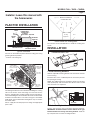
HOUSING
MOUNTING
BRACKET
CEILING
JOIST
POWER
CABLE
TRIM RING / BAFFLE
FINISHED CEILING
4" ROUND
DAMPER/DUCT
CONNECTOR &
4” ROUND
DUCTWORK
PLAN THE INSTALLATION
The unit can be installed anywhere between ceiling joists using
mounting brackets provided.
* Install in a flat ceiling only.
Typical Installation
The ducting from this fan to the outside of the building has a strong
effect on the air flow, noise and energy use of the fan. Use the
shortest, straightest duct routing possible for best performance,
and avoid installing the fan with smaller ducts than recommended.
Insulation around the ducts can reduce energy loss and inhibit
mold growth. Fans installed with existing ducts may not achieve
their rated airflow.
Plan to supply the unit with proper line voltage and appropriate
power cable.
INSTALLATION
2. Mark mounting location.
Position unit between joists and extend mounting brackets.
IMPORTANT: Position brackets so there will be an 1/8” gap
between bottom of housing and ceiling material. Mark the
top of keyhole slot on all four mounting brackets.
COOKING AREA
Do not install above
or inside this area
Cooking
Equipment
Floor
45
45
The unit must not be installed above or inside the cooking area
shown.
Do not install in a cooking area.
*
1/8" GAP
1. Install mounting brackets.
Slide the adjustable mounting brackets into the bracket channels
on the housing.
Bend the tabs on the cardboard protector and insert protector
into opening in housing.
NOTE: The cardboard protector shields the inside of the housing
from drywall spray and construction dust. Do not remove it until
after construction is completed.
CARDBOARD PROTECTOR
*Purchase
separately.
INSULATION*
(Place around and
over Fan Housing.)
ROOF CAP*
(with built-in
damper)
FAN
HOUSING
POWER
CABLE*
4-IN. ROUND
DUCT*
4-IN.
ROUND
ELBOWS*
Seal gaps
around
Housing.
Seal duct
joints with
tape.
OR
Keep duct
runs short.
WALL CAP*
(with built-in
damper)

Page 3
MODELS 744L • 744RL • 744RNL
HORIZONTAL POWER
CABLE CONNECTION
VERTICAL
POWER CABLE
CONNECTION
WIRING PLATE
WHITE
TO
WHITE
BLUE (FAN)
TO
BLACK
TOP / BACK
OF HOUSING
3-WIRE PLUS
GROUND
POWER
CABLE
GROUND TO
WIRING PLATE
Fan operated with separate on/off switch,
speed control or timer.
Light operated with separate on/off switch.
6. Choose power cable direction.
Remove wiring plate. When re-attached, the wiring plate allows
the power cable to enter unit horizontally or vertically.
7. Connect wiring.
Unit can be wired from outside of housing as shown. Use UL
approved connectors to wire per local codes.
Fan and Light operated with single on/off switch
BLACK (LAMP)
TO RED
WIRING PLATE
WHITE
TO
WHITE
BLUE AND
BLACK
TO BLACK
TOP / BACK
OF HOUSING
2-WIRE PLUS
GROUND
POWER
CABLE
GROUND TO
WIRING PLATE
3. Pound in nails.
Remove unit temporarily, and pound nails partially into joists at
all four marked locations.
4. Hang and secure housing.
Hang unit from nails. Check to make sure that there will be a 1/8”
gap between bottom of housing and ceiling material. Pound nails
tight. For wide joist centers: A #8 x 3/8 self-tapping screw can be
used to join extended brackets together and create a rigid mount.
To ensure a noise-free mount, crimp the bracket channels tightly
around mounting brackets.
FLUSH
5. Attach damper/duct connector.
Snap the damper/duct connector onto housing. Make sure that
tabs on the connector lock in housing slots. (Top of damper/duct
connector will be flush with top of housing.) Install ductwork.
NOTE: Make sure damper flap is in place inside of duct
connector. If it is not:
Squeeze top and bottom of connector
to
snap flap back into place.

Page 4
MODELS 744L • 744RL • 744RNL
80 CFM 50
80 CFM 50
1100709B
10. Attach trim ring / baffle to housing.
Remove the cardboard protector from inside the housing collar.
Use a pencil to insert one end of each spring into the holes on the
lamp bracket. Center trim ring / baffle in ceiling opening.
12. Install bulb. (Bulb not included with Model 744L.)
FINISHED
CEILING
MATERIAL
HOUSING
COLLAR
9. Finish ceiling.
Cut an opening in finished ceiling material for housing collar.
SPRINGS
TRIM RING / BAFFLE
LAMP
BRACKET
CAUTION: Disconnect power at service entrance
before cleaning, servicing, or selecting motor
speed.
CAUTION - RISK OF FIRE: 75W MAX. LAMP
Use R30, BR30, PAR30L, or PAR30LN lamps only (75W
Max.).
For wet locations (tub or shower) - use PAR30L or
PAR30LN (75W Max.) lamp only. Use no other lamp
types.
Do not install a lamp indentified for use only in enclosed
luminaries.
!
8. Select motor speed.
Use rocker switch to select 50 or 80 CFM, based on room size
and desired sound level.
MOTOR
SPEED
SELECTION
SWITCH
CLEARANCE
HOLE
11. Install optional trim ring. (Trim rings not included
with Model 744L.)
If desired, choose either brushed bronze or brushed
nickel trim ring and snap it over the white trim ring/baffle.

Página 5
MODELOS 744L • 744RL • 744RNL
ADVERTENCIA
PARA REDUCIR EL RIESGO DE INCENDIOS, DESCARGAS
ELÉCTRICAS O LESIONES PERSONALES, SIGA LAS
SIGUIENTES PRECAUCIONES:
1. Use la unidad solo de la manera indicada por el fabricante.
Sitiene preguntas, comuníquese con el fabricante a la dirección
o al número telefónico que se incluye en la garantía.
2. Antes de dar servicio a la unidad o de limpiarla, interrumpa el
suministro eléctrico en el panel de servicio y bloquee los medios de
desconexión del servicio para evitar que la electricidad se reanude
accidentalmente. Cuando no sea posible bloquear los medios de
desconexión del servicio, fije firmemente una señal de advertencia
(como una etiqueta) en un lugar visible del panel de servicio.
3. El trabajo de instalación y el cableado eléctrico deben estar a
cargo de personal capacitado, de acuerdo con todos los códigos
y normas correspondientes, incluidos los códigos y normas de
construcción específicos sobre protección contra incendios.
4. Es necesario suficiente aire para que se lleve a cabo una
combustión y una extracción adecuadas de los gases a
través del tubo de humos (chimenea) del equipo quemador
de combustible, con el fin de evitar el contratiro. Siga las
directrices y las normas de seguridad del fabricante del equipo
decalefacción, comolas publicadas por la Asociación Nacional de
Protección contra Incendios (National Fire Protection Association,
NFPA), laSociedad Americana de Ingenieros de Calefacción,
Refrigeración y Aire Acondicionado (American Society for Heating,
Refrigeration and Air Conditioning Engineers, ASHRAE) y las
autoridades normativas locales.
5. Al cortar o perforar a través de la pared o del techo, tenga cuidado
de no dañar el cableado eléctrico ni otros servicios ocultos.
6. Los ventiladores con conductos siempre deben ventearse hacia
el exterior.
7. Nunca coloque el interruptor en un lugar en donde se pueda
alcanzar desde la bañera o ducha.
8. Se puede utilizar un reductor de intensidad a fin de hacer funcionar
la lámpara en esta unidad. Consulte la lista de reductores de
intensidad compatibles en broan.com.
9. Instale esta unidad únicamente en un techo plano.
10. Para usarse únicamente en instalaciones sin clasificación
contraincendios.
11. No se debe usar en espacios que manejen aire ambiental.
12. Si se va a instalar esta unidad sobre una tina o ducha, debe estar
marcada como apropiada para esta aplicación y conectarse a
unGFCI (interruptor accionado por pérdida de conexión a tierra)
enun circuito de derivación protegido.
13. No se debe instalar en un techo que tenga un valor de aislamiento
térmico superior a R60.
14. Esta unidad debe estar conectada a tierra.
PRECAUCIÓN
!
1. Solo para usarse como medio de ventilación general. No debe usarse
para la extracción de materiales o vapores peligrosos o explosivos.
2. Para evitar daños a los cojinetes del motor y rotores ruidosos o
desbalanceados, use el protector de cartón (incluido) para mantener
alejados de la unidad de accionamiento el rocío de yeso, el polvo
de la construcción, etc.
3. Lea la etiqueta de especificaciones del producto para ver información
y requisitos adicionales.
VENTILADOR CON
LÁMPARA LED
EMPOTRADO
LEA Y CONSERVE ESTAS INSTRUCCIONES
Para limpiar el anillo/deflector: Límpielo con una aspiradora que
tenga un cepillo suave como accesorio. También puede sacar el anillo/
deflector y limpiarlo con un trapo suave y detergente o jabónsuave.
Séquelo muy bien antes de volver a instalarlo.
Para limpiar el interior de la cubierta: Saque el anillo/deflector
y aspire el interior de la cubierta con una aspiradora que tenga un
cepillo suave como accesorio.
FUNCIONAMIENTO
El ventilador y la lámpara pueden funcionar con varias combinaciones
de interruptores de encendido/apagado y controles:
• Ventilador y lámpara controlados con un solo interruptor de
encendido/apagado
• Ventilador y lámpara controlados con interruptores de
encendido/apagado separados
• Ventilador controlado con un temporizador
• Ventilador seleccionable PCM - 50 o 80
En la sección “Conexión eléctrica” se describen varias opciones
decableado.
LIMPIEZA
MANTENIMIENTO
El motor está permanentemente lubricado. No lubrique ni desarme el motor.
Si desea consultar la declaración de garantía,
repuestos de servicio, apoyo técnico o para
registrar su producto, visite nuestro sitio web o
llame:
En Estados Unidos: - Broan.com 800-637-1453
o NuTone.com 888-336-6151. En Canadá -
Broan.ca o NuTone.ca 877-896-1119

Página 6
MODELOS 744L • 744RL • 744RNL
Aviso al instalador: Deje este
manual con el dueño de la casa.
CUBIERTA
SOPORTE
DE MONTAJE
VIGUETA
DE TECHO
CABLE ELÉCTRICO
ANILLO/DEFLECTOR
TECHO ACABADO
CONECTOR DEL
REGULADOR DE
TIRO/CONDUCTO
REDONDO DE
4 PULG. (10.2 CM)
Y CONDUCTO
REDONDO DE
4 PULG. (10.2 CM)
PLANEACIÓN DE
LA INSTALACIÓN
Esta unidad se puede instalar en cualquier lugar entre las vigas del
techo usando los soportes de montaje que se proporcionan.
* Instale únicamente en un techo plano.
Instalación típica
Los conductos desde este ventilador hacia el exterior del edificio
tienen un gran efecto sobre el flujo de aire, el ruido y el uso de energía
del ventilador. Utilice el tramo de conductos más corto y recto posible
para obtener un desempeño óptimo y evite instalar el ventilador con
conductos menores que los recomendados. El aislamiento alrededor
de los conductos puede reducir la pérdida de energía e inhibir el de-
sarrollo de moho. Los ventiladores instalados en conductos existentes
podrían no obtener el flujo de aire nominal.
Haga los preparativos para alimentar la unidad con el voltaje de línea
y el cable eléctrico apropiados.
INSTALACIÓN
2. Marque el sitio de montaje.
Coloque la unidad entre las vigas y extienda los soportes de montaje.
IMPORTANTE: Coloque los soportes de tal manera que exista una
separación de 1/8 pulg. (3 mm) entre la parte inferior de la cubierta
y el material del techo. Marque la parte superior de la ranura tipo
bocallave en los cuatro soportes de montaje.
ÁREA DE COCINA
No instale el equipo
sobre o dentro de
estaárea.
Equipo
decocina
Piso
45
45
No se debe instalar la unidad sobre, ni dentro, del área de co-
cinamostrada.
No instale el equipo en un área donde cocine.
*
SEPARACIÓN DE
1/8 pulg. (3 mm)
1. Instale los soportes de montaje.
Deslice los soportes de montaje ajustables en los canales del soporte
de la cubierta.
Doble las lengüetas en el protector de cartón e inserte el protector
en la abertura de la cubierta.
NOTA: El protector de cartón protege el interior de la cubierta contra
el rocío de yeso y el polvo de la construcción. No lo quite hasta que
la construcción esté completa.
PROTECTOR DE CARTÓN
TAPA DE
TECHO*
(con regulador
de tiro integrado)
TAPA DE PARED*
(con regulador
de tiro integrado)
CODOS
REDONDOS
DE 10 CM (4 PULG.)*
CONDUCTO REDONDO
DE 10 CM (4 PULG.)
*
CUBIERTA DEL
VENTILADOR
Selle las
separaciones
alrededor de
la cubierta.
Selle con cinta
las uniones de
los conductos.
Mantenga
cortos los
tramos de
conductos.
AISLAMIENTO
(Coloque alrededor y sobre
la cubierta del ventilador.)
CABLE
ELÉCTRICO*
*Se compra
por separado.
O

Página 7
MODELOS 744L • 744RL • 744RNL
CONEXIÓN DEL
CABLE ELÉCTRICO
HORIZONTAL
CONEXIÓN
DEL CABLE
ELÉCTRICO
VERTICAL
PLACA DE CABLEADO
BLANCO
ABLANCO
AZUL
(VENTILADOR)
ANEGRO
PARTE SUPERIOR/
PARTE POSTERIOR
DE LA CUBIERTA
CABLE ELÉCTRICO
DE TRES HILOS
YCONEXIÓN
A TIERRA
TIERRA A PLACA
DE CABLEADO
Ventilador controlado mediante un interruptor de
encendido/apagado separado, control de velocidad
o temporizador.
Lámpara controlada mediante un interruptor de
encendido/apagado separado.
6. Elija la dirección del cable eléctrico.
Quite la placa de cableado. Una vez reinstalada, la placa de cableado
permite al cable eléctrico entrar a la unidad en sentido horizontal
overtical.
7. Conecte el cableado.
El cableado de la unidad puede hacerse desde afuera de la cubierta,
tal como se muestra. Realice el cableado con conectores aprobados
por UL y en cumplimiento de los códigos locales.
Ventilador y lámpara controlados mediante un
interruptor único de encendido/apagado
ROJO (LÁMPARA)
A ROJO
PLACA DE CABLEADO
BLANCO
ABLANCO
AZUL Y NEGRO
ANEGRO
PARTE
SUPERIOR/PARTE
POSTERIOR DE
LACUBIERTA
CABLE ELÉCTRICO
DEDOS HILOS
YCONEXIÓN
A TIERRA
TIERRA A PLACA
DE CABLEADO
3. Martille los clavos.
Quite temporalmente la unidad y clave parcialmente los clavos
en las vigas en los cuatro lugares marcados.
4. Cuelgue la unidad y asegúrela.
Cuelgue la unidad en los clavos. Compruebe para cerciorarse de
que haya un 3,2 mm (1/8 po) abra entre el fondo de la cubierta y
el material del techo. Clave los clavos firmemente. Para centros
de vigas anchas: Se puede usar un tornillo autorroscante #8 x
3/8 para unir entre sí los soportes extendidos y crear un montaje
rígido. Para lograr un montaje silencioso, doble los canales del
soporte ajustadamente alrededor de los soportes de montaje.
AL RAS
5. Acople el conectador del regulador de tiro/
conducto.
Conecte a presión el conector del regulador de tiro/conducto en
la cubierta. Asegúrese de que las lengüetas del conector queden
fijas en las ranuras de la cubierta. (La parte superior del conector
del regulador de tiro/conducto quedará al ras con la parte superior
de la cubierta.) Instale los conductos.
NOTA: Asegúrese de que la tapa del regulador de tiro esté
colocada dentro del conector del conducto. Si no lo está:
Comprima la parte superior e inferior del conector para
volver a colocar la tapa en su lugar.

Página 8
MODELOS 744L • 744RL • 744RNL
1100709B
10. Acople el anillo/deflector a la cubierta.
Quite el protector de cartón del interior del collar de la cubierta.
Utilice un lápiz para insertar un extremo de cada resorte en los
agujeros que están en el soporte de la lámpara. Centre el anillo/
deflector en la abertura del techo.
12. Instale la bombilla. (Bombilla no incluida con el
modelo 744L.)
MATERIAL
ACABADO
DETECHO
COLLARÍN
DE LA
CUBIERTA
ORIFICIO
DEHOLGURA
9. Termine el techo.
Corte una abertura en el techo terminado para el collarín de
lacubierta.
RESORTES
ANILLO/DEFLECTOR
SOPORTE DE
LALÁMPARA
PRECAUCIÓN: Gire la bombilla para instalarla
o quitarla.
PRECAUCIÓN - RIESGO DE INCENDIO:
LÁMPARA MÁXIMO DE 75 VATIOS
Use únicamente lámparas R30, BR30, PAR30L, o PAR30LN
(máximo de 75 vatios).
Para sitios expuestos a agua (tinas o duchas): use
únicamente la lámpara PAR30L o PAR30LN (máximo de 75
vatios). No utilice ningún otro tipo de lámpara.
No instale una lámpara identificado para el uso solamente
en lumbreras incluidas.
!
80 CFM 50
80 CFM 50
8. Seleccione la velocidad del motor.
Use el interruptor basculante para seleccionar 50 u 80 CFM, según
el tamaño de la habitación y el nivel de sonido deseado.
INTERRUPTOR DE
SELECCIÓN DE
VELOCIDAD DEL
MOTOR
11. Instale el anillo de ajuste opcional. (Anillos de
ajuste no incluidos con el modelo 744L.)
Si lo desea, elija un anillo de bronce cepillado o níquel cepil-
lado y colóquelo sobre el anillo / deflector blanco.
-
 1
1
-
 2
2
-
 3
3
-
 4
4
-
 5
5
-
 6
6
-
 7
7
-
 8
8


