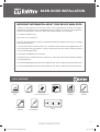
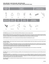
EnVivo 048118071628 Instrucciones de operación
- Tipo
- Instrucciones de operación

ENVIVO BARN DOOR
IMPORTANT INFORMATION ABOUT YOUR ENVIVO BARN DOOR
BARN DOOR INSTALLATION
• Wood is a natural product and can warp, swell, or shrink if exposed to moisture or changes in
temperature. To reduce the risk of damage due to warp, swelling, or shrinking, avoid installing in
areas that are exposed to moisture or where the relative humidity is not controlled.
• For indoor installation only.
• Do not trim or cut the doors.
• Caution: barn door product is heavy and should be lifted by two people to avoid injury or damage
when installing the door.
• To clean the surface of this barn door, use a mild dish soap and warm water applied with a soft
cloth. Always test cleaning products in a small, inconspicuous area, rst. Do not utilize any abrasive
or corrosive cleaning products.
• Clean spills immediately with a soft cloth.
• This barn door kit includes either a 37” x 84” door or a 43” x 84” door and the necessary hardware
to install the product.
• The recommended opening size for the 37” wide door is 28” to 36” in width and up to 83” without trim.
• The recommended opening size for the 43” wide door is 34” to 42” in width and up to 83” without trim.
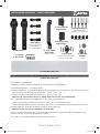
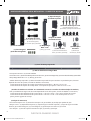
TOOLS REQUIRED:
RESIDENTIAL WOOD DOORS
RESIDENTIAL WOOD DOORS
R
ESIDE
N
TIA
L
W
O
O
D
D
O
O
R
S
RESIDENTIAL WOOD DOORS
RESIDENTIAL WOOD DOORS
R
ESIDE
N
TIA
L
W
O
O
D
D
O
O
R
S
Measuring
Tape
Pencil Stud Finder
(for drywall installation only)
Drill Set of
Drill Bits
13 mm & 16 mm
Wrench
13 mm Socket
Wrench
#2 Phillips
Screw Driver
Level
1
Envivo Barn Door Info & Install (E&S) Guide.indd 1 7/26/19 9:37 AM

ENVIVO BARN DOOR
- Strap Hardware – (2) Bent Straps
- Strap Bolts – (4 ) 2-3/8” Strap Mounting Bolts, (4) Hex Nuts, (4) Cap Nuts, (8) Washers
- 7-1/2 ” Matte Black Handle – (1) Handle, (2) Screws
- Primed Mounting Board – (1) Primed Wood Board for drywall installation only (size dependent on door width, see details below)
• The 37” Door Primed Mounting Board Dimensions = 78-3/4” x 3-1/2 ” x 1/2 ”
• The 43” Door Primed Mounting Board Dimensions = 90-3/4” x 3-1/2 ” x 1/2 ”
- Rail – (1) Matte Black Sliding Rail (size dependent on door width, see details below)
• The 37” Door Sliding Rail Dimensions = 78-3/4” x 1-9/16” x 1/4 ” and has 5 mounting holes
• The 43” Door Sliding Rail Dimensions = 90-3/4” x 1-9/16” x 1/4 ”. It is two pieces with a splice and has 5 mounting holes.
- Rail Mounting Bolts – (5) Rail Mounting Bolts, (5) Washers, (5) Drywall Anchors
- Common Hardware – (5) Wall Spacers, (1) Left Cushioned Angle Stopper, (1) Right Cushioned Angle Stopper, (4) Hex
Screws, (1) Hex Key, (2) Anti-Jump Bumpers with (2) Screws
- Floor Guide – (1) Floor Mounted Door Guide, (2) Screws, (2) Anchors
INSTALLATION OVERVIEW - WHAT’S INCLUDED
RESIDENTIAL WOOD DOORS
RESIDENTIAL WOOD DOORS
R
ESIDE
N
TIA
L
W
O
O
D
D
O
O
R
S
(2) Bent Straps
(1) Hex Key
(4) Hex Screws
(2) Anti-Jump
Bumpers
(2) Screws
(5) Wall Spacers
(1) Left Cushioned
Angle Stopper
(1) Right Cushioned
Angle Stopper
(4) Strap Bolts
(4) 2-3/8” Strap Mounting
Bolts, (4) Hex Nuts,
(4) Cap Nuts, (8) Washers
(1) 7-1/2” Matte
Black Handle
(1) Handle, (2) Screws
(1) Floor Guide
(1) Floor Mounted Door Guide,
(2) Screws, (2) Anchors
(5) Rail Mounting Bolts
(5) Rail Mounting Bolts,
(5) Washers, (5) Drywall Anchors
(1) Primed Mounting Board
(1) Matte Black Sliding Rail
(Wood screws not provided. 10# 2-1/2” Phillips head wood screws are recommended.)
(Masonry anchors for concrete installation not provided)
2
Envivo Barn Door Info & Install (E&S) Guide.indd 2 7/26/19 9:37 AM

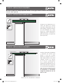
ENVIVO BARN DOOR
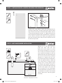
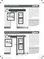
PASO 1 – INSTALACION DE LA PUERTA DE BARRA CINTA DOBLADA
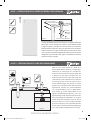
STEP 2 - ANTI-JUMP BUMPER INSTALLATION
The barn door comes ready to install, with pre-drilled holes for
mounting the bent strap. To install the bent strap, place the bent
strap on the front of the door and install the bolts, washers, and nuts
in the order demonstrated in (Figure 1-1). Tighten and secure the
2-3/8” strap bolts and washers using a socket wrench. It’s important
to use a wrench to hold the nuts in place as you tighten the strap
bolts with the socket wrench. Also, be sure to install the hex nuts
rst and the cap nuts last.
Measure 10” on the top of the door
panel from both ends and mark
lightly with a pencil (Figure 2-1). Place
the anti-jump bumpers on top of the
door so they are centered on the pencil
mark. Rotate the bumpers so that the
offset screw hole is facing the side of the
door that has the bent strap hardware
attached to it (Figure 2-2). Drill 1/8”
pilot hole through the anti-jump bumper’s
screw hole approximately ½” deep and
use a screw driver to install the screw
making sure to not fully tighten (Figure
2-3). Rotate the bumpers, pivoting on
the screw, so that the bumpers overhang
the door face (Figure 2-4). Once the
door is placed on the rail, the bumpers
can be rotated back into position so that
it is centered on the door and centered
directly under the rail. Then fully tighten
the screws.
Figure 2-1 Figure 2-2
Figure 2-3
Figure 1-1
RESIDENTIAL WOOD DOORS
RESIDENTIAL WOOD DOORS
R
ESIDE
N
TIA
L
W
O
O
D
D
O
O
R
S
RESIDENTIAL WOOD DOORS
RESIDENTIAL WOOD DOORS
R
ESIDE
N
TIA
L
W
O
O
D
D
O
O
R
S
10” 10”
Figure 2-4
3
Figure 1-1 Front Door Face
CAP NUT
STRAP BOLT
HEX NUT
WASHER
WASHER
Envivo Barn Door Info & Install (E&S) Guide.indd 3 7/26/19 9:37 AM

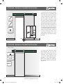
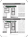
ENVIVO BARN DOOR
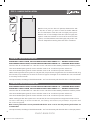
Based on how your barn door will operate, determine the side
of the door on which you want to install the handle. Measure
40” from the bottom of the door and mark lightly with a pencil.
Measure over 2” from the edge of the door and mark lightly with
a pencil. Center the hardware on the axis of the marks and with
a pencil, mark the hardware screw holes lightly and pre-drill 1/8”
hole 1/2” deep before installing the screws with a screwdriver.
40”
STEP 3 - HANDLE INSTALLATION
RESIDENTIAL WOOD DOORS
RESIDENTIAL WOOD DOORS
R
ESIDE
N
TIA
L
W
O
O
D
D
O
O
R
S
DRYWALL INSTALLATION NOTES:
CONCRETE INSTALLATION NOTES:
• This barn door kit includes either a 37” x 84” door or a 43” x 84” door and the necessary hardware to install the product.
• The recommended opening size for the 37” wide door is 28” to 32” in width and up to 83” without trim.
• The recommended opening size for the 43” wide door is 34” to 38” in width and up to 83” without trim.
• When installing the barn door system into a drywall wall, the primed mounting board and rail must be secured using
wood screws (not provided) into the studs of the wall to support the weight of the installed door. Use a stud nder
to accurately locate the studs.
• For optimal results, the sliding rail should be centered 1-1/2” from the nearest jamb when the door is in the open position.
• This barn door kit includes either a 37” x 84” door or a 43” x 84” door and the necessary hardware to install the product.
• The recommended opening size for the 37” wide door is 28” to 32” in width and up to 83” without trim.
• The recommended opening size for the 43” wide door is 34” to 38” in width and up to 83” without trim.
• When installing the barn door system into a concrete wall, do not use the primed mounting board include in this kit.
• To secure the sliding rail to the concrete wall, use masonry wall anchors (not provided) in conjunction with
the rail mounting bolts.
Note: masonry wall anchors are not provided with this kit. 5/16” x 1-3/4” zinc alloy masonry wall anchors are
recommended.
• For optimal results, the sliding rail should be centered 1-1/2” from the nearest jamb when the door is in the open position.
4
FOR DRYWALL INSTALLATION, FOLLOW INSTRUCTIONS STEPS LABELED “A” – DRYWALL INSTALLATION.
FOR CONCRETE INSTALLATION, FOLLOW INSTRUCTIONS STEPS LABELED “B” – CONCRETE INSTALLATION.
FOR CONCRETE INSTALLATION, FOLLOW INSTRUCTIONS STEPS LABELED “B” – CONCRETE INSTALLATION.
FOR DRYWALL INSTALLATION, FOLLOW INSTRUCTIONS STEPS LABELED “A” – DRYWALL INSTALLATION.
Envivo Barn Door Info & Install (E&S) Guide.indd 4 7/26/19 9:37 AM

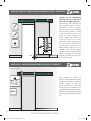
ENVIVO BARN DOOR
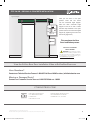
STEP 4A/4B – DRYWALL & CONCRETE INSTALLATION
A C
B
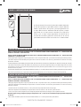
85-3/4” 85-3/4” 85-3/4”
Figure 4-1
Figure 4-2
Installation Line
Figure 4-3
To achieve the correct amount of
clearance for the barn door, measure
85-3/4” from the floor with a
measuring tape in three different
locations equal distance apart
spanning the length of your rail as
shown in image (a, b, c) and mark
with a pencil (Figure 4-1). Then,
using a level, determine which
measurement is the highest
(Figure 4-2). With a pencil, mark a
horizontal installation li n e tha t
extends beyond the opening
on both sides (Figure 4-3).
The installation line represents the
center of the sliding rail.
RESIDENTIAL WOOD DOORS
RESIDENTIAL WOOD DOORS
R
ESIDE
N
TIA
L
W
O
O
D
D
O
O
R
S
STEP 5A - DRYWALL INSTALLATION
Figure 5-1Figure 5-1
Figure 5-5 Figure 5-5
Figure 5-4
1-1/2”
Locate the studs near the opening
by using a stud nder. With a pencil,
mark where the studs intersect the
horizontal installation line on either
side of the opening (Figure 5-1).
Next, nd the center of the primed
mounting board and mark it lightly
with pencil (Figure 5-2). Position the
mounting board so that the center is
1-1/2” from the interior edge of the
jamb (Figure 5-3). Ensure the primed
mounting board is level along the
installation line at center (Figure
5-4). Pre-drill a pilot hole (size of
drill bit dependent on size of wood
screw) into the mounting board then
secure the mounting board to the wall
by screwing wood screws into the studs
with a screw driver or cordless screw
driver (Figure 5-5).
RESIDENTIAL WOOD DOORS
RESIDENTIAL WOOD DOORS
R
ESIDE
N
TIA
L
W
O
O
D
D
O
O
R
S
Figure 5-2
Figure 5-3
5
Note: Wood screws are sold separately. For additional support, drywall anchors can also
be utilized in conjunction with the wood screws but are also sold separately.
Envivo Barn Door Info & Install (E&S) Guide.indd 5 7/26/19 9:37 AM

ENVIVO BARN DOOR
STEP 6A - DRYWALL INSTALLATION
STEP 5B – CONCRETE INSTALLATION
Figure 6-2
Figure 6-1
1-1/2”
RESIDENTIAL WOOD DOORS
RESIDENTIAL WOOD DOORS
R
ESIDE
N
TIA
L
W
O
O
D
D
O
O
R
S
RESIDENTIAL WOOD DOORS
RESIDENTIAL WOOD DOORS
R
ESIDE
N
TIA
L
W
O
O
D
D
O
O
R
S
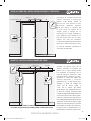
Position the sliding rail in the center
of the primed mounting board
making certain it is level and mark
the holes in the sliding rail using a
pencil (Figure 6-1). Pre-drill 3/8”
holes through the mounting board
and into the drywall (Figure 6-2).
Do not use the primed mounting board included in this kit when installing into a concrete wall. Skip to Step 6B.
6
STEP 6B - CONCRETE INSTALLATION
1-1/2”
Locate the center of the sliding
rail and position it so that it is
1-1/2” from the jamb (Figure 6-1).
Position the rail in place ensuring
that it is level, mark the holes on the
rail using a pencil (Figure 6-2) and
pre-drill holes in masonry with
suitable bit for 5/16” concrete
anchors (not provided).
Note: When purchasing masonry
wall anchors, 5/16” x 1-3/4” zinc
alloy anchors are recommended.
Figure 6-2
Figure 6-2
RESIDENTIAL WOOD DOORS
RESIDENTIAL WOOD DOORS
R
ESIDE
N
TIA
L
W
O
O
D
D
O
O
R
S
Installation Line
Envivo Barn Door Info & Install (E&S) Guide.indd 6 7/26/19 9:37 AM

ENVIVO BARN DOOR
7
14 5 32
STEP 7A - DRYWALL INSTALLATION
When installing the sliding rail,
rst insert the drywall anchors, wall
spacers, the sliding rail, and secure
on the primed mounting board
using the rail mounting bolts (with
washers) provided, securing with
a socket wrench (Figure 7-1). For
ease, secure in the order shown in
the diagram (starting with number
1 through 5).
Note: You may need to pre-insert
the left and right cushioned angle
stoppers inside the outer holes on
the rail, depending on where you
want your barn door to stop (Figure
7-2). The cushioned angle stoppers’
hex screws will be tightened later
in the installation process.
RESIDENTIAL WOOD DOORS
RESIDENTIAL WOOD DOORS
R
ESIDE
N
TIA
L
W
O
O
D
D
O
O
R
S
Figure 7-2 (Left)
Figure 7-2 (Right)
Figure 7-2
Figure 7-2
Figure 7-1
WALL SPACER
DRYWALL ANCHOR
WASHER
RAIL MOUNTING BOLT
STEP 7B - CONCRETE INSTALLATION
1-1/2”
14 5 32
When installing the sliding rail, rst
install the masonry anchors. Next,
place the wall spacers on top of the
anchors. Then secure the sliding
rail directly to the wall with the rail
mounting bolts and washers. Be sure
the rail mounting bolts pass through
the washer, mounting rail, wall spacers
and into the masonry anchors (Figure
7-1). For ease, secure in the order
shown in the diagram (starting with
number 1 through 5).
Note: You may need to pre-insert
the left and right cushioned angle
stoppers inside the outer holes on
the rail, depending on where you
want your barn door to stop (Figure
7-2). The cushioned angle stoppers’
hex screws will be tightened later in
the installation process.
RESIDENTIAL WOOD DOORS
RESIDENTIAL WOOD DOORS
R
ESIDE
N
TIA
L
W
O
O
D
D
O
O
R
S
Figure 7-2 Figure 7-2
Figure 7-1
WALL SPACER
MASONRY ANCHOR
WASHER
RAIL MOUNTING BOLT
Figure 7-2 (Left)
Figure 7-2 (Right)
Envivo Barn Door Info & Install (E&S) Guide.indd 7 7/26/19 9:37 AM

ENVIVO BARN DOOR
8
STEP 8A/8B – DRYWALL & CONCRETE INSTALLATION
Floor Guide
Figure 8-1
To install the oor-mounted guide,
place the door on the sliding rail
by centering the wheels of the bent
straps on the sliding rail. Then open
the door. Place the guide 1-1/2”
from the edge of the door frame
and insert the oor-mounted guide
into the groove at the bottom of the
door. Mark the holes of the guide on
the oor with a pencil (Figure 8-1)
and pre-drill with 1/8” drill bit prior
to screwing the guide into place with
a screw driver (Figure 8-2). The oor
guide anchors should be used with
all types of ooring except hard-
wood. When installing into hard-
wood ooring, use only the screws
provided.
RESIDENTIAL WOOD DOORS
RESIDENTIAL WOOD DOORS
R
ESIDE
N
TIA
L
W
O
O
D
D
O
O
R
S
1-1/2”
Figure 8-1
STEP 9A/9B – DRYWALL & CONCRETE INSTALLATION
Figure 9-1 Closed
To secure the cushioned angle
door stoppers, rst start with the
door in the closed position. Place a
cushioned angle stopper on the
rail so that it meets the bent strap
hardware in the closed position.
Secure the stopper by tightening
the internal screw with the hex key
(Figure 9-1).
Figure 9-1
RESIDENTIAL WOOD DOORS
RESIDENTIAL WOOD DOORS
R
ESIDE
N
TIA
L
W
O
O
D
D
O
O
R
S
Figure 8-2
Envivo Barn Door Info & Install (E&S) Guide.indd 8 7/26/19 9:37 AM

Figure 9-2 Open
STEP 9A/9B – DRYWALL & CONCRETE INSTALLATION
RESIDENTIAL WOOD DOORS
RESIDENTIAL WOOD DOORS
R
ESIDE
N
TIA
L
W
O
O
D
D
O
O
R
S
9
Figure 9-2
Next, put the door in the open
position. Insert two hex screws
into the cushioned angle stopper.
Place the other cushioned angle
stopper on the rail so that it meets
the bent strap hardware in the open
position. Secure the cushioned angled
stopper by tightening the screw with
the hex key (Figure 9-2).
This completes the Barn
Door Installation process.
TSCA TITLE VI COMPIANT
PROP 65 WARNING
WARNING: This product can expose
you to chemicals including respirable wood
dust which is known in the State of California
to cause cancer. For more information go to
www.P65Warnings.ca.gov/wood
©2019 VT Industries, Inc. All rights reserved.
All trademarks and registered trademarks are the property of their respective owners.
RESIDENTIAL WOOD DOORS
RESIDENTIAL WOOD DOORS
RESIDENTIAL WOOD DOORS
HOLSTEIN, IOWA FACILITY
1000 INDUSTRIAL PARK
P.O. BOX 490
HOLSTEIN, IA 51025
SAN ANTONIO, TEXAS FACILITY
1732 UNIVERSAL CITY BLVD.
UNIVERSAL CITY, TX 78148
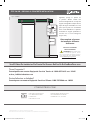
View the EnVivo Barn Door Installation Video at EnVivoBarnDoor.com
VTINDUSTRIES.COM
Have Questions?
Contact our Technical Service Team at 1-800-827-1615 ext.10345 or [email protected]
Missing or Damaged Parts?
Contact our Customer Service Team at 1-888-787-2366 ext. 18239
Envivo Barn Door Info & Install (E&S) Guide.indd 9 7/26/19 9:37 AM

Envivo Barn Door Info & Install (E&S) Guide.indd 10 7/26/19 9:37 AM

Envivo Barn Door Info & Install (E&S) Guide.indd 11 7/26/19 9:37 AM

PUERTA DE GRANERO ENVIVO
INFORMACION IMPORTANTE DE SU PUERTA DE GRANERO ENVIVO
INSTALACION DE
PUERTA DE GRANERO
• La madera es un producto natural y puede deformarse, hincharse o encogerse si se expone a la
humedad o cambios en la temeratura. Para reducer el riesgo de daños debidos a la deformacion,
hinchazon o encogimiento, evite la instalacion en areas que estan expuestas a la humedad o donde
la humedad relative no esta controlada.
• Solo para instalacion en interiores
• No recorte ni corte las puertas
• Precaucion: el producto de la puerta de granero es pesado y debe ser levantado por dos personas
para evitar lesions o daños.
• Para limpiar la supercie de esta puerta de granero, use un jabon suave y agua tibia aplicada con
un paño suave. Siempre pruebe los productos de limpieze en un area pequeña y discrete, primero.
No utilize ningun abrasivo o productos de limpieza corrosivos.
• Limpie los derrames inmediatamente con un paño suave.
• Este juego de puerta de granero incluye una puerta de 37” x 84” o una puerta de 43” x 84” y los
accesorios necesarios para instalar el producto.
• El tamaño de aperture recomendado para la puerta de 37” de ancho es de 28” a 36” de ancho y
de hasta 83” sin molduras.
• El tamaño de aperture recomendado para la puerta de 43” de ancho es de 34” a 42” de ancho y
de hasta 83” sin molduras.
HERRAMIENTAS NECESARIAS:
RESIDENTIAL WOOD DOORS
RESIDENTIAL WOOD DOORS
R
ESIDE
N
TIA
L
W
O
O
D
D
O
O
R
S
RESIDENTIAL WOOD DOORS
RESIDENTIAL WOOD DOORS
R
ESIDE
N
TIA
L
W
O
O
D
D
O
O
R
S
Cinta Metrica Lapiz Buscador De Viga
(solo para instalacion de pared de yeso)
Taladro Juego De Brocas
Para Taladro
13mm & 16 mm
Llave Inglesa
13 mm Llave
De Tubo
Destornillador
Phillips #2
Nivelador
1
Envivo Barn Door Info & Install (E&S) Guide.indd 20 7/26/19 9:37 AM

PUERTA DE GRANERO ENVIVO
- Herrajes Para Correas – (2) Correas Dobladas
- Pernos de Correa – (4) Pernos de Montaje de Correa de 2-3/8”, (4) Tuercas Hexagonales, (4) Tuercas de Sombrerete, (8) Arandelas
- Manija Negra Mate de 7-1 / 2 ” – (1) Manija, (2) Tornillos
- Tablero de Montaje Imprimado: (1) Tablero de madera imprimado solo para instalacion en paneles de yeso (el tamaño
depende de ancho de la puerta, consulte los detalles a continuacion)
• Las dimensiones de la placa de montaje imprimada para puerta de 37”= 78-3/ 4” x 3-1 / 2 ” x 1 / 2 ”
• Las dimensiones de la placa de montaje de 43” con imprimacion para puerta = 90-3/ 4” x 3-1 / 2 ” x 1 / 2 ”
- Riel- (1) Riel desilizante negro mate (el tamaño depende del ancho de la puerta, consulte los detalles a continuacion)
• Las dimensiones del riel deslizante de la puerta de 37” = 78-3/ 4” x 1-9/16” x 1 / 4 ” y tiene 5 oricios de montaje.
• Las dimensiones del riel deslizante de la puerta de 43” = 90-3/ 4” x 1-9/16” x 1 / 4 ”. Es dos piezas con un em
palme y tiene 5 agujeros de montaje.
- Pernos de montaje en riel – (5) Pernos de montaje en riel, (5) Arandelas, (5) Anclajes para paneles de yeso.
- Manijas comun – (5) Separadores de pared, (1) Tope de angulo acolchado izquierdo, (1) Tope de angulo acolchado
derecho, (4) Tornillos Hexagonal, (1) Llave hexagonal, (2) parachoques anti-salto con (2) tornillos
- Guia del piso – (1) Guia de la puerta montada en el piso, (2) Tornillos, (2) Anclajes.
DESCRIPCION GENERAL DE LA INSTALACION – LO QUE ESTA INCLUIDO
RESIDENTIAL WOOD DOORS
RESIDENTIAL WOOD DOORS
R
ESIDE
N
TIA
L
W
O
O
D
D
O
O
R
S
(2) Correas Dobladas
(1) Llave Hexagonal
(4) Tornillos Hexagonales
(2) Parachoques
Anti-saltos
(2) Parachoques
Anti-saltos, (2) Tornillos
(5) Separadores de Pared
(1) Tapon de Angulo
Acolchado Izquierdo
(1) Tapon de AnGulo
Acolchado Derecho
(4) Tornillos de Correa
(4) Pernos de Montaje de Correa 2-3/8”,
(4) Tuercas Hexagonales,
(4) Tuercas de Tapa, (8) Arandelas
(1) Manija Negra
Mate 7-1/2”
(1) Manija, (2) Tornillos
(1) Guia de Piso
(1) Guia de Puerta Montada en
el Piso, (2) Tornillos, (2) Anclajes
(5) Tornillos de Montaje en Carril
(5) Tornillos de Montaje en Carril,
(5) Arandelas, (5) Anclajes Para Pared de Yeso
(1) Placa de Montaje Imprimada
(1) Riel de Deslizamiento Negro Mate
(Tornillos de madera no incluidos. Se recomiendan 10# 2-1/2” tornillos de cabeza Phillips de madera.)
(Anclajes de masoneria)
2
Envivo Barn Door Info & Install (E&S) Guide.indd 19 7/26/19 9:37 AM

PUERTA DE GRANERO ENVIVO
3
PASO 1 – INSTALACION DE LA PUERTA DE BARRA CINTA DOBLADA
PASO 2 – INSTALACION ANTI-JUMP DE PARACHOQUES
La puerta del establo viene lista para instalarse, con agujeros perforados
para montar la correa doblada. Para instalar la correa doblada, apriete
y asegure los pernos y arandelas d la correa de 2-3/8” con una llave de
tubo para apretar y asegurar la manija. Es importante usar una llave para
sujetar las tuercas en su lugar mientras aprieta los pernos de la correa
con la llave de tubo. Ademas asegurese de instalar primero las tuercas
hexagonales y las tuercas de la tapa. (Figura 1-1) demuestra el orden de
los pernos tuercas y arandelas.
Mida 10” en la perte superior de l panel de la
puerta desde ambos extremos y marque liger-
amente con un lapiz (Figura 2-1). Coloque los
protectors contra saltos en la parte superior de
la puerta para que esten centrados. Gire los
topes de manera que el oricio del tornillo de
compensacion este orientado hacia el lado de
la puerta que tiene la pieza de sujecion de la
correa doblada (Figura 2-2). Perfore un oricio
pilot de 1/8” a traves del oricio del tornillo del
parachoques anti-salto de aproximadamente
1/2” de profundidad y use un destornillador
para instalar el tornillo asegurandose de no
apretar completamente (Figura 2-3). Gire los
parachoques girando sobre el tornillo de modo
que los parachoques sobresalgan de la parte
frontal de lapuerta (Figura2-4). Una vex que la
puerta se coloca en el riel, los topes se pueden
girar hacia su posicion para que quede centrado
en la puerta y centrado directamente debajo del
riel. Luego apriete completamente los tornillos.
Figura 2-1 Figura 2-2
Figura 2-3
Figure
RESIDENTIAL WOOD DOORS
RESIDENTIAL WOOD DOORS
R
ESIDE
N
TIA
L
W
O
O
D
D
O
O
R
S
RESIDENTIAL WOOD DOORS
RESIDENTIAL WOOD DOORS
R
ESIDE
N
TIA
L
W
O
O
D
D
O
O
R
S
10” 10”
Figura 2-4
3
Figura 1-1 Cara De La Puerta Delantera
TUERCAS
DE TAPA
TORNILLOS DE CORREA
TUERCAS HEXAGONALES
ARANDELAS
ARANDELAS
Envivo Barn Door Info & Install (E&S) Guide.indd 18 7/26/19 9:37 AM

PUERTA DE GRANERO ENVIVO
En function de como funcionara la puerta de su establo, determine
el lado de la puerta en el que desea instalar la manija. Mida 40”
desde la parte inferior de la puerta y marque ligeramente con
un lapiz. Mida mas de 2” desde el borde de la puerta y marque
ligeramente con un lapis. Centre la cerradura en el eje de las
marcas y con un lapiz, marque ligeramente los oricios de los
tornillos de la cerradura y perfore un oricio de 1/8” de 1/2” de
profundidad antes de instalar los tornillos con un destornillador.
40”
PASO 3 – INSTALACION DE MANIJA
RESIDENTIAL WOOD DOORS
RESIDENTIAL WOOD DOORS
R
ESIDE
N
TIA
L
W
O
O
D
D
O
O
R
S
NOTAS DE INSTALACION DE PARED DE YESO:
NOTAS DE INSTALACION DE CONCRETO
• Este juego de puerta de granero incluye una puerta de 37” x 84” o una puerta de 43”x 84” y los accesorios necesarios para instalar el producto.
• El tamaño de aperture recomendado para la puerta de 37” de ancho es de 28” a 32” de ancho y de hasta 80-1/2” de altura con borde y
de hasta 83” sin borde.
• El tamaño de aperture recomendado para la puerta de 43” de ancho es de 34” a 38” de ancho y de hasta 80-1/2” de altura con borde y 83” sin borde.
• Al instalar el sistema de la puerta del establo en el panel de yeso, la placa de montaje imprimada y el riel deben asegurarse con tornillos
para madera (no provistos) en los pernos de la pared para soportar el peso de la puerta instalada. Utilice un buscador de viga para locali
ocalizerrecision los pernos.
• Para obtener resultados optimos, el riel deslizante debe estar centrado a 1-1/2” de la jamba mas cercana cuando la puerta esta en la posicion abierta.
• Al instalar en paneles de yeso, la placa de montaje imprimada debe usarse junto con los pernos y anclajes de montaje del riel
• Este juego de puerta de granero incluye una puerta de 37” x 84” o una puerta de 43” x 84” y la cerradura necesaria para instalar el producto.
• El tamaño de aperture recomendado para la puerta de 37” de ancho es de 28” a 32” de ancho y de hasta 80-1/2” en altura con recorte y
hasta 83” sin recortar.
• Cuando instale en una pared de concreto, no use la placa de montaje imprimada incuida en este juego.
• El tamaño de aperture recomendado para la puerta de 43” de ancho es de 34” a 38” de anch oy hasta en altura.
• Junto con los pernos de montaje del riel, use anclajes de pared de mamposteria para asegurar el riel al pared de concreto.
Nota: Este juego no incluye anclajes de pared para mamposteria. 5/16” x 1-3/4” zinc Se recomiendad anclajes de pared de mamposteria
de aleacion.
• Para obtener resultados optimos el centro del riel debe instalarse a 1-1/2” de la posicion de la jamba abierta
4
PARA LA INSTALACION DE CONCRETO, SIGA LAS INSTRUCCIONES PASOS ETIQUETADOS “A” – INSTALACION EN
PARED DE SECADO A CONTINUACION
PARA LA INSTALACION DE PAREDES DE YESO, SIGA LA INSTRUCCIONES PASOS ETIQUETADOS “B” – INSTALACION DE
CONCRETO A CONTINUACION
PARA LA INSTALACION DE PAREDES DE YESO, SIGA LA INSTRUCCIONES PASOS ETIQUETADOS “B” – INSTALACION
DE CONCRETO A CONTINUACION
PARA LA INSTALACION DE CONCRETO, SIGA LAS INSTRUCCIONES PASOS ETIQUETADOS “A” – INSTALACION EN
PARED DE SECADO A CONTINUACION
Envivo Barn Door Info & Install (E&S) Guide.indd 17 7/26/19 9:37 AM

PUERTA DE GRANERO ENVIVO
PASO 4A /PASO 4B – INSTALACION DE PARED Y CONCRETO
A C
B
85-3/4” 85-3/4” 85-3/4”
Figura 4-1
Figura 4-2
Linea De Instalacion
Figura 4-3
Para lograr la cantidad correcta de
espacio libre para la puerta del
establo, mida 85-3/4” desde el
piso con una cinta metrica en tres
ubicaciones diferentes distancia
igual que abarca la longitud de
su carril como se muestra en la
imagen (a,b,b) y marque con un
lapiz (Figura 4-1). Luego utilizando un
nivel, determine que medida es la
mas alta (Figura 4-2). Con un lapiz,
marque una linea de instalacion
horizontal que se extienda mas alla de la
abertura en ambos lados (Figura 4-3).
La linea de instalacion representa el
centro del riel deslizante.
RESIDENTIAL WOOD DOORS
RESIDENTIAL WOOD DOORS
R
ESIDE
N
TIA
L
W
O
O
D
D
O
O
R
S
PASO 5A – INSTALACION DE PARED DE YESO
Figura 5-1Figura 5-1
Figura 5-5 Figura 5-5
Figura 5-4
1-1/2”
Localisce los pernos cerca de la
abertura utilizando un buscador de
pernos. Con un lapiz, marque donde
los montantes se intersecan con la
linea de instalacion horizontal a cada
lado de la abertura (Figura 5-1). Luego,
encuentre el centro del tablero de
montaje imprimado y marquelo
igeramente con un lapiz (Figura 5-2).
Coloquee la placa de montaje de
modo que el centro quede a
1-1/2” de el interior del borde
jamba (Figura 5-3). Asegurese de que
la placa de montaje imprimada este
nivelada a lo largo de la linea de instalacion
en el centro (Figura 5-4). Perfore previa-
mente un oricio piloto (el tamaño de la
broca depende del tamaño del tornillo de
madera) en la placa de montaje y luego
asegure la placa de montaje a la pared
atornillando los tornillos de madera en
los pernos con un destornillador o un
destornillador inalambrico (Figura 5-5).
RESIDENTIAL WOOD DOORS
RESIDENTIAL WOOD DOORS
R
ESIDE
N
TIA
L
W
O
O
D
D
O
O
R
S
Figura 5-2
Figura 5-3
5
Nota: Los tornillos para madera se venden por separado. Para soporte adicional,
los anclajes para paneles de yeso tambien pueden se utilizara junto con los.
Envivo Barn Door Info & Install (E&S) Guide.indd 16 7/26/19 9:37 AM

PUERTA DE GRANERO ENVIVO
PASO 6A – INSTALACION DE PARED DE YESO
PASO 5B – INSTALACION DE CONCRETO
Figura 6-2
Figura 6-1
1-1/2”
RESIDENTIAL WOOD DOORS
RESIDENTIAL WOOD DOORS
R
ESIDE
N
TIA
L
W
O
O
D
D
O
O
R
S
RESIDENTIAL WOOD DOORS
RESIDENTIAL WOOD DOORS
R
ESIDE
N
TIA
L
W
O
O
D
D
O
O
R
S
Coloque el riel deslizante en el
centro de laplaca de montaje
imprimada asegurandose de que
este nivelada y marque los oricios
en el riel deslizante con un lapiz
(Figura 6-1). Taladre previamente
agujeros de 3/8” a traves de la
placa de montaje y en el panel de
yeso (Figura 6-2).
No utilice el tablero de montaje imprimado incluido en este juego cuando lo instale en una instalacion de
conrecto. Salta al paso 6B.
6
PASO 6B – INSTALACION DE CONCRETO
1-1/2”
Localice el centro del riel deslizante
y colóquelo de manera que
quede a 1-1/2” de la jamba
(Figura 6-1). Coloque el riel en su
lugar asegurándose de que esté
nivelado, marque los orificios
en el riel con un lápiz (Figura
6-2) y perfore previamente los
agujeros en la mampostería con una
broca adecuada para anclajes de
concreto de 5/16”(no se proporciona).
Nota: Al comprar anclajes de pared
de mampostería, se recomiendan
anclajes de aleación de zinc de
5/16“ x 1-3/4”
Figura 6-2
Figura 6-2
RESIDENTIAL WOOD DOORS
RESIDENTIAL WOOD DOORS
R
ESIDE
N
TIA
L
W
O
O
D
D
O
O
R
S
Linea De Instalacion
Envivo Barn Door Info & Install (E&S) Guide.indd 15 7/26/19 9:37 AM

PUERTA DE GRANERO ENVIVO
7
14 5 32
PASO 7A – INSTALACION DE PARED DE YESO
RESIDENTIAL WOOD DOORS
RESIDENTIAL WOOD DOORS
R
ESIDE
N
TIA
L
W
O
O
D
D
O
O
R
S
Figura 7-2
(Izquierdo)
Figura 7-2
(Derecho)
Figura 7-2
Figura 7-2
Figura 7-1
SEPARADORES DE PARED
ANCLAJES PARA PARED DE YESO
ARANDELAS
TORNILLOS DE MONTAJE EN CARRIL
PASO 7B – INSTALACION DE CONCRETO
1-1/2”
14 5 32
Al instalar el riel deslizante,
primero instale los anclajes de
mamposteria. A continuacion,
coloque los separadors de
pared en la parte superior de los
anclajes. Luego asegure el riel
deslizante directamente a la pared
con los pernos y arandelas de
montaje del riel. Asegurese de
que los pernos de montaje del riel
pasan a traves de la arandela, el
riel de montaje, los espaciadores
de pared y hacia los anclajes de
mamposteria (Figura 7-1). Para
mayor facilidad, asegurelo en el
orden que se muestra en el diagram
(comenzando con el numer 1 al 5).
Nota: Es possible que deba inserter
previamente los topes de ang lo
acochoados a la ezquierda y a la
derecha dentro de los orificios
Al instalar el riel deslizante,
primero inserte los anclajes
para paneles de yeso, los
separadores de pared, el riel
deslizante y asegú los en el tablero
de montaje imprimado utilizando
los pernos de montaje del riel (con
arandelas) provistos, asegurándolos
con una llave de tubo (Figura 7-1).
Para mayor facilidad, asegúrelo en
el orden mostrado en el diagrama
(comenzando con el número 1 al 5).
Nota: Es possible que deba
inserter previamente los topes de
angulo acolchados a la izquierda y
a la derecha dentro de los oricios
externos del riel, dependiendo de
donde desea que se detenga la
puerta de su establo ( Figura 7-2).
RESIDENTIAL WOOD DOORS
RESIDENTIAL WOOD DOORS
R
ESIDE
N
TIA
L
W
O
O
D
D
O
O
R
S
Figura 7-2 Figura 7-2
Figura 7-2
(Izquierdo)
Figura 7-2
(derecho)
Figura 7-1
SEPARADORES DE PARED
ANCLAJES PARA PARED DE YESO
ARANDELAS
TORNILLOS DE MONTAJE EN CARRIL
Envivo Barn Door Info & Install (E&S) Guide.indd 14 7/26/19 9:37 AM

PUERTA DE GRANERO ENVIVO
8
PASO 8A/ PASO 8B – INSTALACION DE PARED DE YESO Y CONCRETO
Guia de piso
Figura 8-1
Para instalar la guia montada en el
piso, coloque la puerta en el riel
desllizante y abra la puerta.
Coloque la guia 1-1/2” del borde
del marco de la puerta y inserte
la guia montada en el piso en la
ranura en la parte inferior de la
puerta. Marque los oricios de
la guia en el piso con un lapiz
(Figura 8-1) y perfore previamente
con una broca de 1/8” antes de
atornillar la guia en su lugar con un
destornillador (Figura 8-2). Los
anclajes de guia de piso deben
usarse con todos los tipos de pisos
exepto la madera dura. Al instalar
en pisos de mader dura, use solo
los tornillos provistos.
RESIDENTIAL WOOD DOORS
RESIDENTIAL WOOD DOORS
R
ESIDE
N
TIA
L
W
O
O
D
D
O
O
R
S
1-1/2”
Figura 8-1
PASO 9A/9B – INSTALACION DE PARED DE YESO Y CONCRETO
Figura 9-1 Cerrado
Para asegurar los topes de
puerta con angulo acolchado, primero
comience con la puerta en la posicion
cerrada. Coloque un tope de
angulo acolchado en el riel para
que se junte con el hardware de la
correa doblada en la posicion cerrada.
Asegure el tope apretando el tornillo
interno con la llave hexagonal (Figura
9-1).
Figura 9-1
RESIDENTIAL WOOD DOORS
RESIDENTIAL WOOD DOORS
R
ESIDE
N
TIA
L
W
O
O
D
D
O
O
R
S
Figura 8-2
externos de riel, dependiendo
de donde esea que se detenga la
puerta de su establo (Figura 7-2).
Envivo Barn Door Info & Install (E&S) Guide.indd 13 7/26/19 9:37 AM

Figura 9-2 Abrió
STEP 9A/9B – DRYWALL & CONCRETE INSTALLATION
RESIDENTIAL WOOD DOORS
RESIDENTIAL WOOD DOORS
R
ESIDE
N
TIA
L
W
O
O
D
D
O
O
R
S
9
Figure 9-2
Siguiente, ponga la puerta en
la posicion abierta. Inserte dos
tornillos hexagonales en el tope de
angulo amortiguado. Coloque el otro
tope de angulo acolchado en el riel
para que se junte con el hardware
de la correa doblada en la posicion
acolchado en angulo apretando el
tornilllo con la llave hexagonal
(Figura 9-2).
Esto complete el proceso
de instalacion de Puerta
de Granero
TSCA TITLE VI COMPIANT
PROP 65 ADVERTENCIA
ADVERTENCIA: Este producto puede
exponerte a sustancias químicas, incluso
aserrin que el estado de California reconoce
como causante de cáncer. Para más información,
visita www.P65Warnings.ca.gov/wood
©2019 VT Industries, Inc. Todos los derechos reservados.
Todas las marcas comerciales y marcas registradas son propiedad de sus respectivos dueños.
RESIDENTIAL WOOD DOORS
RESIDENTIAL WOOD DOORS
RESIDENTIAL WOOD DOORS
HOLSTEIN, IOWA FACILITY
1000 INDUSTRIAL PARK
P.O. BOX 490
HOLSTEIN, IA 51025
SAN ANTONIO, TEXAS FACILITY
1732 UNIVERSAL CITY BLVD.
UNIVERSAL CITY, TX 78148
Vea El Video De Instalacion De Puerta De Granero EnVivo En EnVivoBarnDoor.com
VTINDUSTRIES.COM
Tiene Preguntas?
Comuniquese con nuestro Equipo de Servicio Tecnico al 1-800.827.1615 ext. 10345
Partes faltantes o dañadas?
Comuniquese con nuestro Equipo de Servicio al Cliente 1-888-787-2366 ext. 18239
Envivo Barn Door Info & Install (E&S) Guide.indd 12 7/26/19 9:37 AM
-
 1
1
-
 2
2
-
 3
3
-
 4
4
-
 5
5
-
 6
6
-
 7
7
-
 8
8
-
 9
9
-
 10
10
-
 11
11
-
 12
12
-
 13
13
-
 14
14
-
 15
15
-
 16
16
-
 17
17
-
 18
18
-
 19
19
-
 20
20


EnVivo 048118071628 Instrucciones de operación
- Tipo
- Instrucciones de operación
En otros idiomas
Documentos relacionados
Otros documentos
-
ZTE Light Guía del usuario
-
ReliaBilt 07-2892 Guía de instalación
-
 TRUporte NL52-W9-GY1-36 Guía de instalación
-
ReliaBilt 07-3045 Manual de usuario
-
-
-
JELD-WEN JW226900021 Guía de instalación
-
 connexx KIT M-Core R-Li 80 Guía del usuario
-
 Educational Insights Design & Drill® Flower Power Studio™ Product Instructions


