


1
Thank you for purchasing a Rogue XP or XPe wheelchair!
Please do not use this wheelchair without first reading this entire manual. BEFORE
riding, you should be trained in the safe use of this chair by an Assistive Technology
Practitioner (ATP) or clinical professional.
If you have any questions or concerns about any aspect of this wheelchair, this manual,
or the service provided by us or your retail supplier, please do not hesitate to contact
us by telephone at:
715-254-0991
In writing at:
Ki Mobility
5201 Woodward Drive
Stevens Point, WI 54481
U.S.A
Or via email at:
Or via our Authorized EU Representative:
James Leckey Design
19C Ballinderry Road
Lisburn
BT28 2SA
Phone: 0800 318265 (UK) or 1800 626020 (ROI)
www.leckey.com
I. INTRODUCTION

2
I. INTRODUCTION
II. TABLE OF CONTENTS
III. NOTICE - READ BEFORE USE
A. Your Safety and Stability ...................................................................... 4
IV. WARNINGS
A. Signal Words........................................................................................ 5
B. General Warnings................................................................................. 6
C. Positioning Belts .................................................................................. 7
D. Riding Your Wheelchair........................................................................ 8
E. Power Drives........................................................................................ 9
F. Ascending Stairs.................................................................................. 9
G. Descending Stairs................................................................................ 9
H. Transfers............................................................................................. 10
I. Your Wheelchair and the Environment................................................. 10
J. Modifying your Wheelchair .................................................................. 11
K. Wheelchair Stability............................................................................. 11
V. SET UP & USE OF YOUR WHEELCHAIR
A. Your Rogue XP & It’s Parts ................................................................. 14
B. Transit Use.......................................................................................... 15
C. Height-Adjustable T-Arms ................................................................... 18
D. Padded Swing-Away Adjustable Armrests .......................................... 19
E. Pediatric T-Arm Adjustment ................................................................ 20
F. Armrest Warnings ............................................................................... 21
G. Center of Gravity Adjustment .............................................................. 21
H. Wheel Camber.................................................................................... 23
I. Wheelbase Width Adjustment ............................................................. 24
J. Setting Toe to Zero ............................................................................. 25
K. Replacing the Camber Tube................................................................ 26
L. Front Seat Height Adjustments............................................................ 30
M. Rear Seat Height Adjustment .............................................................. 31
N. Caster Angle Adjustment..................................................................... 32
O. Wheel Installation & Removal............................................................... 33
P. Adjusting the Footrest ......................................................................... 34
Q. Optional Angle Adjustable Footplate.................................................... 35
R. Folding Backrest ................................................................................. 36
S. Backrest Angle Adjustment ................................................................. 37
T. Adjusting Backrest Height................................................................... 39
U. Adjusting, Removing and Replacing Backrest Release Cable for Width
Growth................................................................................................ 40
II. TABLE OF CONTENTS

3
V. Adjusting Backrest Position................................................................. 41
W. Replacing Adjustable Backrest Rigidizer Bar ....................................... 42
X. Wheel Locks ....................................................................................... 43
Y. Growing Your Rogue XP in Width........................................................ 44
Z. Anti-Tips ............................................................................................. 45
AA. Cushion Installation ............................................................................. 46
BB. Upholstery Fabric ................................................................................ 47
CC. Adjusting and/or Growing Seat Upholstery.......................................... 47
DD. Rogue XP Standard 5th Wheel (Optional) ............................................ 49
EE. Rogue XP Dynamic 5th Wheel (Optional)............................................. 50
FF. Inserting Growth Spacer into Cross Tube............................................ 52
VI. MAINTENANCE
A. Inspecting Your Rogue XP Wheelchair ................................................ 53
B. Cleaning Your Rogue XP Wheelchair................................................... 55
C. Storage............................................................................................... 55
VII. WARRANTY ................................................................................................. 56
II. TABLE OF CONTENTS

4
III. NOTICE - READ BEFORE USE
A. Your Safety and Stability
Ki Mobility manufactures many different wheelchairs that might meet your needs. You should
consult an Assistive Technology Professional when selecting which model would best meet your
particular requirements and how the wheelchair should be set up and adjusted. Final selection of
the type of wheelchair, options and adjustments rests solely with you and your medical
professional. The options you choose and the set-up and adjustment of the wheelchair have a
direct impact on its stability. Factors to consider that affect your safety and stability are:
a. Your personal abilities and capabilities including strength, balance and coordination.
b. The types of hazards and obstacles you might encounter during your day.
c. The specific dimensions, options and set up. In particular, the seat height, seat depth, seat
angle, back angle, size and position of the rear wheels and size and position of the front
casters. Any change to any of these items will change the stability of your wheelchair. You
should only make changes after consulting with a qualified professional.

5
IV. WARNINGS
A. Signal Words
Within this manual you will find what are referred to as “Signal” words. These words are used to
identify and convey the severity of varying hazards. Before using this chair you, and each person
who may assist you, should read this entire manual. Please note the Signal word and consider any
warnings, cautions or dangers. Make sure to follow all instructions and use your chair safely. The
Signal word refers to a hazard or unsafe practice that may cause severe injury or death to you or
to other persons. The “Warnings” are in three main categories, as follows:
DANGER – Danger indicates an imminently hazardous situation which, if not avoided, will result in
serious injury or death.
WARNING – Warning indicates a potentially hazardous situation which, if not avoided, could
result in serious injury or death.
CAUTION – Caution indicates a potentially hazardous situation which, if not avoided, could result
in injury or damage to your wheelchair.
These signal words will be placed throughout the manual, where appropriate to highlight the
hazardous situation. Refer to the following list for hazardous situations that will apply to the general
use of this wheelchair.

6
IV. WARNINGS
B. General Warnings
WARNING: Do not exceed the weight limit of 200 pounds for the Rogue XP. This is the
combined weight of user and all items carried. Exceeding the weight limit can cause
damage to your chair or increase the likelihood of a fall or tip back resulting in severe injury
or death to the user or others.
DANGER: Do not use this chair for weight training.The movement of the additional weight
will alter the center of gravity of the wheelchair increasing the likelihood of a tip-over which
can cause damage to your chair or cause severe injury or death to the user or others.
WARNING: If your wheelchair is equipped with inflatable tires, make sure the tires have
been inflated to the correct tire pressure as indicated on the side wall of the tire. Your
wheelchair provider can determine if you have inflatable tires. Using your wheelchair without
properly inflated tires can have an effect on the stability of the wheelchair causing it to tip over
resulting in death or injury to the user or others.
DANGER: Do not attempt to push your wheelchair up or down ramps or traverse across a
slope of greater than 9 degrees. This is dangerous and increases the likelihood of a fall or tip
back resulting in severe injury or death to the user or others.
WARNING: Do not attempt to push your wheelchair up an incline that is slick or coated
with ice, oil or water. This can cause an unstable situation resulting in death or injury to the
user or others.
DANGER: Do not lean over the side or back of the wheelchair to extend your reach. This
may cause you to fall out of the wheelchair or the wheelchair to tip over resulting in injury or death.

7
IV. WARNINGS
B. General Warnings
DANGER: Do not attempt to the lift the wheelchair by holding on to removable parts such
as the arms or footrests. Only lift the wheelchair by holding on to the frame. This may cause a fall
or loss of control and result in serious injury or death.
CAUTION: Do not over tighten the bolts and hardware that attaches various components
together on the frame.
This could cause serious damage and affect the safety and durability of
the wheelchair.
C. Positioning Belts
Positioning belts are designed to assist with proper positioning within the wheelchair. They are
not designed as seat belts. Use positioning belts ONLY to help support the user’s posture.
Misuse of positioning belts may cause severe injury to or death of the user.
• Ensure the user does not slide underneath the positioning belt in the wheelchair seat. If this
occurs, the user’s breathing may be hampered causing death or serious injury.
• The positioning belt should have a snug fit; tight enough to hold their position, but not so
tight as to restrict breathing. Y o u s h o u l d b e a b l e t o s l i d e y o ur hand between the positioning
belt and the user.
• NEVER Use Positioning Belts:
a. As a restraint. A restraint requires a doctor’s order.
b. On a user who is unconscious.
c. As an occupant restraint in a motor vehicle. A positioning belt is not designed to
replace a seat belt that is attached to the frame of a vehicle, which would be required
of an effective seat belt. During a sudden stop, with the force of the stop, the user
would be thrown forward. Wheelchair seat belts will not prevent this, and further
injury may result from the belts or straps.
DANGER: Failure to comply with the instruction above could result in serious injury or death.

8
IV. WARNINGS
D. Riding Your Wheelchair
Your chair is designed for use on solid, flat surfaces such as concrete, asphalt and flooring. Use
caution if you push your wheelchair on a wet or slick surface.
WARNING: Do not push your chair in sand, loose soil or over rough terrain. This may cause
a loss of stability and result in a fall or loss of control and cause serious injury or death.
DANGER: In most states, wheelchairs are not legal for use on public roads. If you find you must
push on a public road, be alert to the danger of motor vehicles. Use of a wheelchair on a public
road can cause serious injury or death.
WARNING: Obstacles and road hazards (such as potholes and broken pavement) can
damage your chair and may cause a fall, tip-over or loss of control. Failure to comply with
this instruction could result in serious injury or death.
DANGER: Do not ride your wheelchair on an escalator. Use of a wheelchair on an escalator can
cause serious injury or death.
To minimize these risks:
1) Keep a lookout for danger-scan the area well ahead of your chair as you ride.
2) Make sure the floor areas where you live and work are level and free of obstacles.
3) Remove or cover threshold strips between rooms.
4) Install a ramp at entry or exit doors. Make sure there is not a drop off at the bottom
of the ramp.
5) To Help Correct Your Center of Balance:
a. Lean your upper body FORWARD slightly as you go UP over an obstacle.
b. Press your upper body BACKWARD as you go DOWN from a higher to a
lower level.
6) If your chair has anti-tip tubes, lock them in place before you go UP over an obsta-
cle.
7) Keep both of your hands on the handrims as you go over an obstacle.
8) Never push or pull on an object (such as furniture or a doorjamb) to propel your
chair.
9) Do not operate your wheelchair on roads, streets or highways.
10) Do not attempt to push over obstacles without assistance.

9
IV. WARNINGS
E. Power Drives
Ki Mobility does not recommend the installation of power drive systems on any Rogue XP
wheelchair.
Rogue XP wheelchairs have not been designed or tested as power wheelchairs. If you add a
power drive system to a Rogue XP wheelchair, be sure the manufacturer of the power drive
system has validated and approved the combination of the power drive system and Rogue XP
wheelchair as safe and effective.
WARNING: Use of a power drive system that has not been properly validated could result
in serious injury or death.
F. Ascending Stairs
• Have at least two people, who have sufficient strength and skill to handle the weight of the
user and wheelchair, assist when trying to go up a set of stairs in this wheelchair.
• Move the wheelchair and user backwards up the stairs.
• Position one person behind the user, one person in front. The person in front must hold
onto a non-removable part of the wheelchair.
• The rear attendant tilts the chair back and they both lift together. Take one step at a time.
• This may require the anti-tips be flipped up or removed. Make sure the anti-tips are
reattached or flipped back down before using the wheelchair.
DANGER: Failure to comply with the instructions above could result in serious injury or death.
G. Descending Stairs
• When descending a set of stairs the user should be facing forward.
• A person behind the user, who has sufficient strength and skill to handle the weight of the
user and the wheelchair, should tilt the chair backward and let the chair down the stairs
one step at a time on the rear wheels.
• This may require that anti-tips be flipped up or removed. Make sure the anti-tips are
reattached or flipped back down before using the wheelchair.
DANGER: Failure to comply with the instructions above could result in serious injury or death.

10
IV. WARNINGS
H. Transfers
A transfer requires good balance and stability. You should receive training from your therapist
before attempting to do a transfer on your own.
• Before transferring out of your wheelchair every caution should be taken to reduce the gap
between the two surfaces.
• Engage the wheel locks to lock the rear wheels.
• Rotate the casters forward to increase the wheelbase of the wheelchair.
• Remove or swing away the footrests.
• Have someone assist you unless you are well experienced in transfers.
It is dangerous to transfer on your own. It requires good balance and agility. Be aware there is a
point during every transfer when the wheelchair seat is not below you.
WARNING: Failure to comply with the instructions above may cause a fall or loss of
control, which may result in serious injury or death.
I. Your Wheelchair and the Environment
• Your wheelchair is made of many different materials including metal and fabric.
Exposure to water or excessive moisture may cause the metal in the wheelchair to rust
or corrode and the fabric to tear. Dry your chair as soon as possible if exposed to water.
• DO NOT USE YOUR WHEELCHAIR IN A SHOWER, POOL OR BODY OF WATER. This will
cause your wheelchair to rust or corrode and eventually fail.
• Do not operate your wheelchair in sand. Sand can get into the wheel bearings and moving
parts. This will cause damage and eventually will cause the wheelchair to fail.
• Make sure any ramp, slope or curb cut you may attempt to ride on is compliant with ADA
guidelines. Riding across, up or down any slope that is too great may cause a loss of
stability.
ADA Guidelines and more information about accessible design are available at:
http://www.ada.gov/
WARNING: Failure to comply with the instructions above may cause a fall or loss of
control, which may result in serious injury or death.

11
IV. WARNINGS
J. Modifying your Wheelchair
Your wheelchair was engineered and manufactured under s t r i c t d e s i g n c o n t r o l s . A n i n t e g r a l p a r t o f
this process is ensuring the various components work together correctly; they have been tested to
various standards to ensure quality and are approved to work together.
YOU SHOULD NOT CHANGE, ADD OR REMOVE COMPONENTS OR OTHERWISE MODIFY
THIS WHEELCHAIR. NO ONE SHOULD MODIFY THIS WHEELCHAIR EXCEPT BY
ASSEMBLING APPROVED OPTIONS. THERE ARE NO APPROVED OPTIONS THAT INVOLVE
DRILLING OR CUTTING THE FRAME BY ANYONE OTHER THAN A TRAINED KI MOBILITY
ASSOCIATE. Contact Ki Mobility or an authorized Ki Mobility supplier before adding any
accessories or components not provided by Ki Mobility.
DANGER: Failure to comply to these instructions may cause the wheelchair to fail and result in
serious injury or death.
K. Wheelchair Stability
To ensure proper stability of your wheelchair, you must make sure the center of gravity and the
wheelchairs base of support is correct for your balance and abilities. Many factors can affect these
two elements;
Generally, the most important factor is the position of the rear wheels for rearward stability. There
are other actions than can have an adverse effect on your stability. You should consult with your
wheelchair provider and clinicians familiar with your needs and capabilities in determining how this
affects your use.
WARNING: Moving the rear wheels forward increases the likelihood of the wheelchair
tipping backwards. Make small adjustments and proceed slowly until you learn the new balance
point of your wheelchair. Failure to comply with the instruction above could result in serious injury
or death.
WARNING: The farther rearward you place the front casters the greater the likelihood of
the wheelchair tipping forwards. If possible, have your casters mounted forward and whenever
doing a static activity which involves shifting your weight, rotate the casters forward to increase
your wheel base. Failure to comply with this instruction above could result in serious injury or
death.
• Seat height
• Size and position of rear wheels
• Size and position of front casters
• Any seating system components
•Seat depth
•Back angle

12
IV. WARNINGS
K. Wheelchair Stability
WARNING: Always have a qualified technician set up your wheelchair with the accessories
you plan to use daily.
Changes to how you sit or changes in your weight require your chair to be readjusted by a
qualified technician. Always use anti-tips while you acclimate to any changes in your chair set
up. Failure to comply with the instruction above could result in serious injury or death.
WARNING: Changes to your Center of Gravity during your daily activities may occur many
times a day, changing and affecting the stability of your wheelchair. You should be aware of
these activities and take precautions to minimize the risk of a fall. Failure to comply with
the instruction above could result in serious injury or death.
WARNING: Dressing in your wheelchair produces movements and momentary positions that
can reduce stability. Ensure that your anti-tips are in place and rotate your casters forward.
Failure to comply with the instruction above could result in serious injury or death.
WARNING: Be very careful when reaching for objects if this movement requires you to shift
in your seat. This changes your center of gravity. Ensure that your anti-tips are in place.
Failure to comply with the instruction above could result in serious injury or death.
WARNING: Pushing up an incline shifts your center of gravity rearward and can reduce
stability. Ensure your anti-tips are in place. Failure to comply with the instruction above
could result in serious injury or death.
WARNING: If attempting a wheelie to get over a curb or obstacle, ensure your anti-tips are in
place and lean forward. Do not attempt a wheelie unless you have been trained and always
have an attendant behind you to provide assistance if needed. Failure to comply with the
instruction above could result in serious injury or death.

13
IV. WARNINGS
K. Wheelchair Stability
WARNING: Placing items on the back or front of your wheelchair, such as a backpack or
briefcase, alters the balance and center of gravity of the wheelchair. Since the weight of
these items can vary greatly at each use do not assume you are accustomed to the balance
point. Failure to comply with the instruction above could result in serious injury or death.
BE AWARE THAT CARRYING HEAVY OBJECTS ON YOUR WHEELCHAIR CAN HAVE AN
ADVERSE EFFECT ON THE BALANCE WHICH MAY CAUSE A TIP-OVER WHICH MAY
RESULT IN SERIOUS INJURY OR DEATH TO THE USER.
WARNING: Ensure your anti-tips are in place. You should discuss how you plan to use your
wheelchair or any changes you are planning with your clinician. Failure to comply with this
instruction may create a potential hazardous situation which, if not avoided, could result in
serious injury or death.

14
V. SET UP & USE OF YOUR WHEELCHAIR
A. Your Rogue XP & It’s Parts
1. Inspect and maintain this chair. See MAINTENANCE on page 53.
2. If you detect a problem, make sure to service or repair the chair before use.
3. Have a complete inspection, safety check and service of your chair performed by an
authorized supplier annually.
WARNING: Failure to read or comply with these instructions may result in damage to your
wheelchair, a fall, or loss of control causing severe injury to the user or others.

15
V. SET UP & USE OF YOUR WHEELCHAIR
B. Transit Use
It is always safest to transfer out of your wheelchair onto a seat in a motor vehicle with appropriate
seat and shoulder belts. Never use this wheelchair as a seat in a motor vehicle unless it has
been equipped with the Transit Option.
The Rogue XP Series wheelchair equipped with the Transit Option has been tested to and passed
the RESNA WC-4:2012, Section 19: Wheelchairs used as seats in motor vehicles and ISO
7176-19:2008 Wheelchairs -- Part 19: Wheeled mobility devices for use as seats in motor
vehicles. RESNA and ISO standards are designed to test the structural integrity of the wheelchair
as a seat for use in a motor vehicle. These standards are also designed to create compatibility with
Wheelchair Tie-down and Occupant Restraint Systems (WTORS).
Not all configurations of the Rogue XP Series wheelchairs are compatible with the Transit Option. Ki
Mobility manages the configuration and does not offer the Rogue XP Series wheelchair except in
compatible configurations. If you make changes to your Rogue XP Series wheelchair after your
receive it, you should contact your wheelchair provider or Ki Mobility to make sure it is appropriate to
continue to use your wheelchair as a seat in a motor vehicle.
If your Rogue XP Series wheelchair is equipped with the Heavy Duty Option and the Transit Option
you should not use it as a seat in a motor vehicle if you weigh more than 200 lbs.
Aftermarket seating may have replaced the original equipment seat and back support designed and
tested as part of the Transit Option. Your wheelchair provider should tell you if the seating they
provided is original equipment or replacement aftermarket seating. A complete system of wheelchair
frame, seating, Wheelchair Tie-down and Occupant Restraint Systems and a properly equipped
motor vehicle, that have all complied with the standards mentioned in this section, should be in place
before using a Rogue XP Series wheelchair equipped with the Transit Option as a seat in a motor
vehicle.
When using your wheelchair as a seat in a motor vehicle you should always observe the following
instructions:
• The rider must be in a forward-facing position.
• The rider and all items carried must not weigh more than 200 lbs.
• Backpacks and pouches should be removed and secured separately in the motor vehicle. In
the event of an accident these items can become dangerous projectiles, which may injure or
kill you or other occupants of the motor vehicle.
• The rider must use a Wheelchair Tie-down and Occupant Restraint System that complies with
RESNA WC-4:2012, Section 18: Wheelchair tie-down and occupant restraint
systems for use in motor vehicles or ISO 10542-1:2012 Technical systems and aids
for disabled or handicapped persons -- Wheelchair tie-down and occupant-restraint
systems -- Part 1: Requirements and test methods for all systems.
• Attach wheelchair tie-downs to the four securement points (two front, two rear) on the Rogue
XP Series wheelchair with the Transit Option (Fig. 1) in accordance with the wheelchair tie-
down manufacturer’s instructions and RESNA WC-4:2012, Section 18 or ISO 10542-
1:2012 - Part 1.
• Attach occupant restraints in accordance with the occupant restraint manufacturer’s
instructions and RESNA WC-4:2012, Section 18 or ISO 10542-1:2012, Part 1.

16
V. SET UP & USE OF YOUR WHEELCHAIR
B. Transit Use
• Use of lap belts, chest straps, shoulder
harnesses, any other positioning strap system
or positioning accessory should not be used,
or relied on as an occupant restraint, unless it
is marked as such by the manufacturer in
accordance with RESNA WC-4:2012,
Section 18 or ISO 10542-1:2012, Part 1.
• Use of headrests, lateral supports or other
positioning accessories should not be used,
or relied on as an occupant restraint, unless it
is marked as such by the manufacturer in
accordance with RESNA WC-4:2012,
Section 18 or ISO 10542-1:2012, Part 1 or RESNA WC-4:2012, Section 20:
Wheelchair seating systems for use in motor vehicles or ISO 16840-4:2009
Wheelchair seating -- Part 4: Seating systems for use in motor vehicles.
• After being fitted and adjusted, the top of the original equipment back upholstery should be
within 3 inches of the top of your shoulder.
• Any aftermarket seating should be tested to comply with RESNA WC-4:2012, Section 20
or ISO 16840-4:2009 - Part 4.
• Attach the seating to the wheelchair frame in accordance with the seating manufacturer’s
instructions and RESNA WC-4:2012, Section 20 or ISO 16840-4:2009 - Part 4.
• Use of lap belts, chest straps, shoulder harnesses, any other positioning strap system or
positioning accessory should not be used, or relied on as an occupant restraint, unless it is
marked as such by the seating manufacturer in accordance with RESNA WC-4:2012,
Section 20 or ISO 16840-4:2009 - Part 4.
• Use of headrests, lateral supports or other positioning accessories should not be used, or
relied on as an occupant restraint, unless it is marked as such by the seating manufacturer
in accordance with RESNA WC-4:2012, Section 20 or ISO 16840-4:2009 - Part 4.
• Aftermarket accessories such as trays, oxygen tank holders, oxygen tanks, IV poles, back
packs, pouches and other items not manufactured by Ki Mobility should be removed and
secured separately in the motor vehicle. In the event of an accident, these items can
become dangerous projectiles which may injure or kill you or other occupants of the motor
vehicle.
• If the wheelchair has been involved in an accident, you should not continue to use it, as it
may have suffered fatigue that may not be visible.
Fig. 1

17
V. SET UP & USE OF YOUR WHEELCHAIR
B. Transit Use
DANGER: Failure to comply with transit use instructions, on pages 15 and 16, could result in
severe injury or death!
NOTE: To obtain copies of RESNA or ISO standards please contact the standards organizations
below:
RESNA
1700 North Moore St., Suite 1540
Arlington, VA 22209
Phone: 703-524-6686
Fax: 703-524-6630
Email: technicalst[email protected]
ANSI/RESNA Standards:
RESNA WC-4:2012, Section 18:
Wheelchair tie-down and occupant restraint systems for use in motor vehicles.
RESNA WC-4:2012, Section 19:
Wheelchairs used as seats in motor vehicles.
RESNA WC-4:2012, Section 20:
Wheelchair seating systems for use in motor vehicles.
International Organization for Standardization (ISO)
ISO Central Secretariat
1, ch. de la Voie-Creuse
CP 56
CH-1211 Geneva 20 Switzerland
Phone: +41 22 749 01 11
Fax: +41 22 733 34 30
Email: [email protected]
ISO Standards:
ISO 10542-1:2012 Technical systems and aids for disabled or handicapped person --
Wheelchair tie-down and occupant-restraint systems -- Part 1:
Requirements and test methods for all systems.
ISO 16840-4:2009 Wheelchair seating -- Part 4:
Seating systems for use in motor vehicles.
ISO 7176-19:2008 Wheelchairs -- Part 19:
Wheeled mobility devices for use as seats in motor vehicles.

18
V. SET UP & USE OF YOUR WHEELCHAIR
C. Height-Adjustable T-Arms
1. Installation
a. Slide the outer armpost into the receiver mounted to the wheelchair frame.
b. The armrest will automatically lock into place. Check to make sure the locking lever is as
shown (Fig. 2:C).
2. Height Adjustment
a. Rotate release lever (Fig. 2:A).
b. Slide armrest pad up or down to desired height.
c. Return lever to locked position against arm post.
d. Push arm pad until upper arm post locks firmly into place. Check to make sure the locking
lever is shown (Fig. 2:A).
3. Removing Armrest
a. Squeeze release lever (Fig. 2:B) and remove the armrest.
4. Replacing Armrest
a. Slide armrest back into receiver.
b. The armrest should lock back into place.
DANGER: Failure to comply with the instructions above may result in the armrest accidentally
disconnecting from the wheelchair and result in a fall or loss of control and may cause serious
injury or death.
DANGER: Never attempt to lift the chair by the armrests; they may break or disconnect resulting
in a fall or loss of control and may cause serious injury or death.
Fig. 2
A
B
C

19
V. SET UP & USE OF YOUR WHEELCHAIR
D. Padded Swing-Away Adjustable Armrests
1. Installation
a. Slide armrest into receiver tube on rear of frame.
Ensuring the pin engages the receiver.
2. Swinging Away
a. Lift armrest up until pin disengages from receiver and
rotate to the side.
3. Removing Armrest
a. Pull armrest straight out of receiver.
4. Adjusting Arm Height
a. Remove armrest from receivers.
b. From inside of backrest mount, remove 6mm screw
(Fig. 3:A) and remove threaded barrel (Fig. 3:B).
c. Select desired height and replace threaded barrel
(Fig. 3:B).
d. Reinsert 6mm screw (Fig. 3:A) into threaded barrel and tighten.
e. Reinsert arm into receiver.
f. Retighten 6mm screw (Fig. 3:A).
g. Repeat on other armrest.
5. Adjusting Receiver Angle
a. From inside of backrest mount, loosen 6mm screw
(Fig. 4:A) and remove M5 screw (Fig. 4:B). You can
now adjust armrest to desired angle.
b. Once desired armrest angle is achieved realign
holes in pivot bracket (Fig. 4:C).
c. Reinsert M5 screw (Fig. 4:B) through locating holes
and tighten.
d. Retighten 6mm screw (Fig. 4:A).
DANGER: These arms offer only a lock against rotation and are designed to bear a downward
force only. They will remove completely if pulled up on and cannot be used to lift or otherwise
handle the chair. Failure to comply with the instructions above may result in the armrest
accidentally disconnecting from the wheelchair and result in a fall or loss of control and may cause
serious injury or death.
Fig. 3
A
B
C
Fig. 4
A
B
C

20
V. SET UP & USE OF YOUR WHEELCHAIR
E. Pediatric T-Arm Adjustment
1. Installation
a. Slide armrest post into receiver on side frame.
Ensuring the pin in lever engages the receiver
(Fig. 5).
2. Removing Armrest
a. Push lever (Fig. 6:A) in towards side guard panel
to release pin from receiver.
b. Pull armrest straight out of receiver.
3. Adjusting Arm Height in Receiver
a. Remove armrest from chair.
b. Remove two 6mm screws from side guards
(Fig. 7:A).
c. Remove M4 screw (Fig. 7:B) from side guard
post stop through side guard post but do not
pull entirely out. Screw can stay in the lever
assembly. Repeat on other arm.
d. Reset the post stop and lever assembly on side
guard post to desired position. Retighten M4 screw (Fig. 7:B). Repeat on other arm.
e. Place side guard in desired position and replace two 6mm screws (Fig. 7:A) to secure side
guard in place. Tighten two 6mm screws. Repeat on opposite arm.
f. Replace armrest assemblies into receiver (Fig. 5).
Fig. 5
Fig. 6
A
Fig. 7
A
B

21
V. SET UP & USE OF YOUR WHEELCHAIR
F. Armrest Warnings
• All Ki Mobility armrests are designed to detach from the chair and will not bear the weight
of this chair.
• NEVER lift this chair by its armrests. The armrests will release and the user may fall.
• Lift this chair only by non-detachable parts of the main frame.
WARNING: Failure to heed these instructions may result in a fall, tip-over or loss of control
causing severe injury to the user or others.
G. Center of Gravity Adjustment
The most important adjustment on your Rogue XP wheelchair is the position of the rear axle.
You can adjust your center of gravity by moving the two camber mount clamps (Fig. 8:A) forward
or rearward on the seat tube (Fig. 8:B).
Moving the camber mount clamps forward shortens the wheelbase and lightens the front end,
making your chair more maneuverable. Moving the camber mounts rearward makes the chair
more stable and less likely to tip over rearward.
NOTE: Changes to the center of gravity may affect the rear seat height (see Rear Seat Height
Adjustment on page 31), toe-in / toe-out of the rear wheels (see Setting Toe to Zero on page 25)
and the squareness of the casters (see Caster Angle Adjustment on page 32). If you change your
center of gravity position, readjust all of these settings if necessary.
NOTE: Adjusting your chair’s center of gravity will require readjusting the location of the wheel
locks (if provided). See Wheel Locks on page 43 for instructions on adjusting the wheel locks.
Fig. 8
B
A

22
V. SET UP & USE OF YOUR WHEELCHAIR
G. Center of Gravity Adjustment
To adjust the center of gravity location:
a. Remove both rear wheels.
b. Loosen the two screws (Fig. 9:C) and nuts that secure the camber mounts (Fig. 9:A and B)
to the seat tubes on each side of the frame.
c. Grasp both sides of the camber tube and move the camber mounts forward or rearward
along the seat tube, aligning holes on frame with holes on camber mount (Fig. 9:D).
d. Make sure the mounts on both sides of the frame are adjusted equally on both sides of the
frame before reinserting screws and nuts. Tighten until secure.
e. Once the camber mount clamps are secured, attach the rear wheels, occupy the chair and
manuever it with a spotter to get a feel for the new adjustment.
WARNING: The more you move your rear wheels forward, the more likely your chair will tip over
backwards. Always make adjustments in small increments and check the stability of your chair
with a spotter to prevent a tip over. We recommend that you use anti-tip tubes until you adapt to
the change and are sure you are not at risk to tip over.
DANGER: Failure to heed these warnings may cause serious injury or death.
Fig. 9
B
C
A
D

23
V. SET UP & USE OF YOUR WHEELCHAIR
H. Wheel Camber
Wheel camber, shown as an angular relationship (Fig. 10) and (Fig. 11), provides greater side-to-
side stability due to the increased width and angle of the wheelbase. It also allows for quicker
turning and greater access to the top of the handrims.
Wheel camber is determined by pairs of interchangeable camber adapters (Fig. 12:B) which are
available from your authorized supplier in 0°, 2°, 4°, 6°, and 8° angles.
X°
Fig. 11
A
Fig. 10
Fig. 12
B

24
V. SET UP & USE OF YOUR WHEELCHAIR
I. Wheelbase Width Adjustment
Adjusting the wheelbase width allows the rider the option to move the wheels closer or further
away from the hips. It also compensates for camber adjustment and gives the proper wheel
spacing to maximize pushing efficiency.
Adjust the wheelbase width:
1. Loosen the nut (Fig. 13:A) with a 24mm wrench and turn the threaded axle sleeve (Fig. 13:B) in
or out to the desired width.
2. Retighten nut.
3. Repeat on opposite side.
Fig. 13
A
B

25
V. SET UP & USE OF YOUR WHEELCHAIR
J. Setting Toe to Zero
NOTE: A wheelchair equipped with 0° camber adapter cannot have a toe-in-toe-out condition.
This adjustment is only required when using 2°, 4°, 6° and 8° camber adapters.
Toe refers to how well the rear wheels of the chair are aligned relative to the ground. It affects how
well the chair will roll. Drag or rolling resistance is optimally minimized when the wheel toe is set to
zero.
Setting the toe to zero:
1. Loosen the two cap screws (Fig. 14:A) (1 per side) that secure the camber tube clamp. Then
loosen set screws (Fig. 14:E), 2 per side.
2. Rotate the camber tube (Fig. 14:C) until the screws (Fig. 14:D) that secure the camber
adapters are level with the ground. The toe is now set at zero.
3. Before tightening the screws (Fig. 14:A and B), make certain that the camber tube is centered
left-to-right relative to the wheelchair frame. There should be an equal gap on both sides or
none at all.
4. Tighten one screw to 80 in/lb (Fig. 14:A) then tighten the screw on the opposite side to 80
in/lbs.
5. Tighten set screws (Fig. 14:B) until securely in place.
Fig. 14
C
A
D
E
B

26
V. SET UP & USE OF YOUR WHEELCHAIR
K. Replacing the Camber Tube
1. To uninstall the camber tube on your Rogue XP wheelchair:
a. Remove rear wheels.
b. Using two 4mm hex (Allen) wrenches, remove 6mm button head screw (Fig. 15:D).
c. Gently press threaded barrel with remaining button head screw (Fig. 15:E) through camber
tube using hex (Allen) wrench.
d. Using a 4mm hex wrench and a 8mm wrench, loosen 5mm socket head screw (Fig. 15:A)
to release clamp.
e. Using a 2.5mm hex wrench, loosen set screws (Fig. 15:B).
f. Slide camber adapter (Fig. 15:G) from end of camber tube (Fig. 15:C)
g. Repeat steps b – f on other side.
h. Slide camber tube to left or right to remove from camber tube clamps. If you have a 5th
wheel receiver it needs to be removed from the camber tube before removing the camber
tube.
Fig. 15
A
C
D
E
B
G

27
V. SET UP & USE OF YOUR WHEELCHAIR
K. Replacing the Camber Tube
2. Instructions for removal with STANDARD 5th wheel (Fig. 16):
a. Remove 5th wheel from receiver and set aside.
b. Using a 3mm hex wrench and 8mm wrench, remove 5mm button head screw from receiver
(Fig. 16:A).
c. Using a 4mm hex wrench, loosen the two 5mm socket head screws (Fig. 16:B) until receiver
slides freely on camber tube.
3. Instructions for removal with DYNAMIC 5th wheel (Fig. 17):
a. Remove 5th wheel from receiver and set aside.
b. Using a 4mm hex wrench and 10mm wrench, remove the two 6mm socket head screws,
washers and locknuts from receiver (Fig. 17:A).
Fig. 16
A
B
Fig. 17
A

28
V. SET UP & USE OF YOUR WHEELCHAIR
K. Replacing the Camber Tube
4. To install the camber tube on your Rogue XP wheelchair:
a. Starting on either left or right side of chair slide end of new camber tube through camber
clamp. If your chair does not have a Standard or Dynamic 5th wheel to skip step c on next
page.
b1.) Instructions for installing Standard 5th wheel receiver on camber tube.
1. Slide 5th wheel receiver onto end of camber tube that has already been inserted
through the camber tube clamp. Receiver should be below camber tube with notched
face towards rear of chair.
2. Slide camber tube into the opposite side camber clamp.
3. Slide receiver to center of camber tube and align hole in tube and receiver.
4. Insert 5mm bolt (Fig. 18:A) into aligned hole. Secure with 5mm nut using a 3mm hex
wrench and 8mm wrench to tighten securely.
5. Using a 4mm hex wrench, tighten the 2.5mm socket head screws securely (Fig. 18:B).
Move to step c on the next page.
b2.) Instructions for installing Dynamic 5th wheel receiver on camber tube.
1. Slide 5th receiver onto end of camber tube that has already been inserted through the
camber tube clamp. 5th wheel receiver should be below camber tube with threaded
barrel facing front of chair.
2. Slide camber tube into the opposite side camber clamp.
3. Slide receiver to center of camber tube and align two holes in tube and two holes in
receiver (Fig. 18:A).
4. Insert 6mm socket head screws (Fig. 18:A) into aligned holes. Secure with 6mm lock-
nuts and flat washers and tighten securely using a 4mm hex wrench and 10mm
wrench. Move to step c on the next page.
Fig. 18
A
C
E
D
B

29
V. SET UP & USE OF YOUR WHEELCHAIR
K. Replacing the Camber Tube
5. To install the camber tube on your Rogue XP wheelchair:
a. Center camber tube in camber clamps.
b. Insert camber adapter into end of camber tube. If using 2°, 4°, or 6° camber adapters,
rotate thin wall of threaded end until it is pointing up and through holes align with through
holes in camber tube.
c. Press threaded barrel (Fig. 19:E) into through holes in camber tube.
d. Using two 4mm hex wrenches, insert 6mm screws (Fig. 19:D) into threaded barrel and
tighten securely.
e. Repeat steps 3 – 5 on opposite side of chair.
f. Reinstall rear wheels. See Setting Toe to Zero on page 25 to ensure wheels are properly set
up and to finish installation of camber tube.
Fig. 19
C
A
D
E
B

30
V. SET UP & USE OF YOUR WHEELCHAIR
L. Front Seat Height Adjustments
The front seat height can be adjusted in ½" increments by repositioning the caster wheel within
the fork.
1. Use two 4mm Allen wrenches to remove the cap screws and push the internally threaded
axle from one hole location and move up or down to desired location.
2. Reposition the two 6mm screws and tighten to 80 in./lbs.
3. Re-square caster wheels as noted, see Caster Angle Adjustment on page 32.
Fig. 20

31
V. SET UP & USE OF YOUR WHEELCHAIR
M. Rear Seat Height Adjustment
Rear seat height can be adjusted by repositioning the Tubular Component System (TCS).
1. Remove your wheels by depressing the buttons on the quick release axle.
2. Use a 4mm Allen wrench and 8mm open end wrench to remove the two bolts (A) holding
the upper and lower mounting brackets together (see Fig. 21). Reposition the mounting
brackets to the desired height and replace the two M5 bolts.
3. Repeat on both sides of the wheelchair.
NOTE: Height adjustments are in ¼ increments.
NOTE: A front caster adjustment should be made to correspond with any change in seat angle.
WARNING: Lowering the seat height at the rear of the seat .5" or 2 positions of .25" increments
will decrease the rearward stability by ½ degree. The more you move your rear wheels forward,
the more likely your chair will tip over backwards.
Always make adjustments in small increments and check the stability of your chair with a spotter
to prevent a tip-over. We recommend that you use anti-tip tubes until you adapt to the change and
are sure you are not at risk to tip over.
DANGER: Failure to heed these warnings may cause serious injury or death.
Fig. 21
A

32
V. SET UP & USE OF YOUR WHEELCHAIR
N. Caster Angle Adjustment
To maintain optimal performance of your Rogue XP, the front caster housing should always be
aligned perpendicular to the ground. Your Rogue XP is shipped aligned. Many of the adjustments
made in properly setting up the wheelchair, however, will result in the caster housing getting out of
alignment.
After all other adjustments are made, you should check your caster housing alignment and realign
if the housing is not perpendicular to the ground.
Adjusting the Caster Angle:
For optimum performance, the caster housing should always be at a 90° angle to the floor
(perpendicular to the ground).
1. To change the angle you will need an M5 Allen wrench.
2. Loosen the M8 button head cap screw (A) on the bottom of the caster housing win
(Fig. 22). Then turn the screw on the top of the caster housing wing (B). Loosening will
begin to tilt the caster forward. By tightening you will turn rearward.
3. Turn until you have aligned the caster stem so it is perpendicular to the floor.
4. Place a large right triangle against the flat surface of the fork as shown (Fig. 23).
5. With the rack and pinion system of the Rogue XP, the casters should always be able to be
square.
Fig. 22
B
A
Fig. 23

33
V. SET UP & USE OF YOUR WHEELCHAIR
O. Wheel Installation & Removal
1. Installing Wheels (Fig. 24)
a. Push in the axle release button on the axle
to allow the locking balls to retract. Make
note of the difference between the
extended and depressed position of the
axle release button and its effect on the
locking balls on the other end of the axle.
b. Insert the axle into the bearing housing on
the wheel if it is separate.
c. Push on quick release button again and slide axle into axle sleeve.
d. Release the button to lock axle in sleeve. If release button does not fully extend and the
locking balls do not move into the locked position after releasing the button, the axle length
needs to be adjusted.
2. Removing Wheels (Fig. 25)
a. Hold the wheel close to the hub and push in the button on the outside end of the axle.
b. While still holding the button, pull the wheel and axle out of the axle sleeve.
NOTE: Review and understand Section O. Wheel Installation & Removal before attempting an
axle adjustment!
3. Adjusting Axles (Fig. 25)
a. To adjust the axle, you will need a 19mm wrench to
turn the adjustment nut. You will also need an 11mm
wrench to securely hold the ball detent end of the axle
to prevent it from turning.
b. If the wheel and axle will not lock into the camber
adapter, the axle requires adjustment. Turn the nut
counter-clockwise approximately ¼ revolution and try to lock the axle into the camber plug.
If it doesn’t lock, continue making small nut adjustments until it securely locks.
c. If the wheel is locked on the chair but there is excessive wheel play (the wheel hub can be
pushed back and forth on the axle), adjust the nut clockwise until there is no perceptible
gap between the wheel and camber tube and the axle is securely locked onto the chair.
DANGER: Make sure the axle push buttons are completely extended and the locking balls on
the inside of the chair are fully engaged before operating the wheelchair. Failure to do so may
result in the wheel falling off and may cause serious injury or death.
Fig. 24
Axle Sleeve
Axle
Axle Release Button
Fig. 25
Turn
Hold

34
V. SET UP & USE OF YOUR WHEELCHAIR
P. Adjusting the Footrest
1. Height Adjustment of Your Footrest:
a. Locate the set screw on each side of the frame (A).
b. Loosen the set screw on each side of the frame using an M3 Allen wrench. Do not remove.
c. Adjust footrest tube up or down to achieve the desired height (B).
d. Ensure both sides are adjusted equally.
e. Retighten each set screw to 40 in./lbs.
Fig. 26

35
V. SET UP & USE OF YOUR WHEELCHAIR
Q. Optional Angle Adjustable Footplate
1. To adjust the angle of the optional angle adjustable footplates:
a. Loosen, but do not remove, the two M6 screws securing the footplate to the footplate
clamp with a 4mm Allen wrench.
b. Once loose, the footplate will easily rotate around the footrest extension tube.
c. Select the desired position and retighten the two M6 screws to 80 in./lbs.
2. Changing Position of the Optional Aluminum Flip-Up Footplate:
a. Remove both M6 screws from the footplate. There are M6 nylock nuts recessed on the
underside of the clamp. Be sure to prevent these from falling as you loosen the screws.
b. Relocate the footplate once the screws are loose by rotating either forward or rearward
depending on the desired angle. Once position is achieved, reinsert the screws in the
appropriate holes.
c. Fit the nuts into the slot underneath the clamp and tighten the screws securely.
Fig. 27

36
V. SET UP & USE OF YOUR WHEELCHAIR
R. Folding Backrest
1. To fold down the backrest on your Rogue XP:
a. Pull the release cable (Fig. 28:A) that is behind the back frame, outward to release the latch.
Fold downward towards the seat frame (Fig. 29).
b. To latch back into place, pull the release cable outward and the back will release and can be
pushed back into the upright position. The backrest will automatically latch onto the side frame.
c. Ensure a solid engagement onto the latches by pulling back on the backrest frame into the
upright position.
WARNING: Do not occupy or operate chair when backrest is not latched. This may result in a
fall, tip-over or loss of control causing severe injury to the user or others.
Fig. 28
A
Fig. 29

37
V. SET UP & USE OF YOUR WHEELCHAIR
S. Backrest Angle Adjustment
1. Relax Back Feature:
This chair can be adjusted for a slight recline upon releasing the back release cable (Fig. 30:A).
This is referred to as the "relax back feature." 1°, 3° and 6° are available.
2. To Adjust:
a. Use a 3mm Allen key to disassemble the backrest stop (Fig. 30:B) and (Fig. 30:C) and reas-
semble in the desired position on both sides.
Fig. 30
C
A
B
6°
3°
1°

38
V. SET UP & USE OF YOUR WHEELCHAIR
S. Backrest Angle Adjustment
3. To adjust the backrest angle:
a. Loosen 6mm screw (Fig. 31:A) on outside of backrest plate. Do this to each side of back-
rest.
b. Remove 5mm screw (Fig. 31:B) on outside of backrest plate. Do this to each side of back-
rest.
c. Once desired backrest angle is achieved, realign holes in pivot bracket (Fig. 31:C).
d. Reinsert 5mm screw through locating holes and tighten. Repeat on other side of backrest.
e. Retighten 6mm screw (Fig. 31:A). Repeat on other side of backrest.
WARNING: Adjusting the relaxed position or changing the back angle may decrease rearward
stability. Always make adjustments in small increments and check the stability of your chair with a
spotter to prevent a tip-over. Failure to heed these instructions may result in a fall, tip-over or loss
of control causing severe injury to the user or others.
Fig. 31
A
B
C

39
V. SET UP & USE OF YOUR WHEELCHAIR
T. Adjusting Backrest Height
1. To adjust the height of backrest:
a. Remove two 5mm screws from each side of backrest rigidizer bar (Fig. 32:A). (Use of two
3mm Allen wrenches for this adjustment is required.)
b. Using Allen wrench, push the two threaded barrels on each side of backrest rigidizer bar
through screw holes.
c. Grasp upper backrest tube (Fig. 32:B) and move in desired direction of backrest adjust-
ment. Repeat on opposite side.
d. Once desired height is achieved, realign holes in rigidizer bar, upper and lower backrest
tubes. Repeat on opposite side.
e. Reinsert two threaded barrels into aligned holes on each side. Threaded barrels need to
pass through aligned holes in rigidizer bar, lower and upper backrest tubes in order to
secure backrest into place.
NOTE: Rigidizer bar is height adjustable along lower backrest tube.
f. Reinsert two 5mm screws into threaded barrels (Fig. 32:A) on each side and tighten.
WARNING: Secure backrest to avoid injury or bodily harm.
WARNING: Lowering backrest height may decrease rearward stability. Always make
adjustments in small increments and check the stability of your chair with a spotter to prevent a
tip-over. Failure to heed these instructions may result in a fall, tip-over or loss of control causing
severe injury to the user or others.
Fig. 32
A
A
B

40
V. SET UP & USE OF YOUR WHEELCHAIR
U. Adjusting, Removing and Replacing Backrest
Release Cable for Width Growth
1. To adjust the length of the backrest release cable:
a. Hold cable end (Fig. 33:B) securely in place.
b. Turn locking pin (Fig. 33:A) clockwise to tighten (shorten) and counterclockwise to loosen
(lengthen) cable. Cable has been adjusted to optimize function when cable is straight from
end to end. Do not overtighten. Locking pin must engage backrest plate pin housing fully
on each side.
c. Adjust evenly on each end of cable.
2. To remove backrest release cable:
a. Hold cable end (Fig. 33:B) securely in place.
b. Turn locking pin (Fig. 33:A) counterclockwise to unthread cable from pin.
c. Repeat on opposite end of cable.
3. To replace backrest release cable:
a. Remove existing cable. See instructions above in step 2.
b. Align cable end with locking pin (Fig. 33:B).
c. Hold cable end (Fig. 33:B) securely in place while turning locking pin (Fig. 33:A) clockwise to
thread cable into pin. Thread until approximately half of threaded end has been screwed
into locking pin. Repeat on opposite end of cable.
d. Adjust length as needed. See instructions above in step 1.
WARNING: Failure to read or comply with these instructions may result in a fall or loss of control
causing severe injury to the user or others.
Fig. 33
A
B

41
V. SET UP & USE OF YOUR WHEELCHAIR
V. Adjusting Backrest Position
1. To move the location of your Rogue XP backrest:
a. Loosen and remove two M6 flathead screws that attach the backrest plate to the frame.
Repeat on other side.
b. Grasp backrest clamp on each side and move to desired location.
NOTE: Holes in backrest bracket are in ½" increments. It is important to move both sides equally.
c. Replace bolts in backrest bracket, spacing bolts as far from one another as possible (Fig.
34:A). Tighten bolts through bracket and frame until secure. Repeat on other side.
NOTE: When backrest has been moved, adjustments to COG (see Center of Gravity Adjustment
on page 21) and seat upholstery (see Adjusting and/or Growing Seat Upholstery on page 47)
may be required. Always check rearward stability of the wheelchair after adjusting and before use.
WARNING: Moving the backrest rearward can decrease rearward stability of the chair. Always
make adjustments in small increments and check the stability of your chair with a spotter to
prevent a tip-over. We recommend that you use anti-tip tubes.
Fig. 34
A

42
V. SET UP & USE OF YOUR WHEELCHAIR
W. Replacing Adjustable Backrest Rigidizer Bar
1. To remove your adjustable backrest rigidizer bar:
a. Note the back height setting before disassembly.
b. Using two 3mm hex (Allen) wrenches, remove 5mm button head screws from the upper and
lower fasteners in the adjustable backrest rigidizer bar (Fig. 35:A).
c. Using the hex wrench, push the two threaded barrels on each side of adjustable backrest
rigidizer bar through screw holes.
d. Remove the upper back canes and upholstery. If an aftermarket back is used, follow the
instructions provided by the back manufacturer to remove the back.
e. Slide rigidizer bar off backrest tubes.
2. To install the replacement adjustable height backrest rigidizer bar onto the backrest tubes
to complete width adjustment.
a. Slide adjustable rigidizer bar over lower backrest tubes to desired location.
b. Insert upper back tubes with (or without) back upholstery to original or desired height.
c. Align holes in adjustable rigidizer bar with the desired holes in upper and lower back tubes.
d. Reinsert two threaded barrels into aligned holes on each side. Threaded barrels need to
pass through aligned holes in adjustable rigidizer bar, lower and upper backrest tubes in
order to secure backrest into place.
e. Reinsert two 5mm screws into threaded barrels (Fig. 35:A) on each side and tighten with
two 3mm hex wrenches to secure.
DANGER: Do not use or operate wheelchair when adjustable backrest rigidizer is not installed.
Failure to heed this instruction may result in severe injury or death.
Fig. 35
A
A
B

43
V. SET UP & USE OF YOUR WHEELCHAIR
X. Wheel Locks
Rogue XP wheelchairs are shipped with one of several different types of wheel locks pre-installed.
The clamp assembly works the same for all wheel locks.
a. Using a 5mm Allen wrench, turn one of the screws in the clamp until it runs easily (less than
one turn).
b. Repeat the same process with the second of the two screws so the clamp can be adjusted
on the frame.
c. Adjust the clamp toward the rear wheel so when engaged, the wheel lock compresses the
tire and prevents any wheel movement (Fig. 36).
d. Ensure wheel lock arms embed in tires at least 1/8 inch when locked. If you fail to do so, the
locks may not work (Fig. 37).
e. Retighten the screws.
Rear wheel locks are NOT designed to slow or stop a moving wheelchair. Use them only to
keep the rear wheels from rolling when your chair is at a complete stop.
• NEVER use rear wheel locks to try to slow or stop your chair when it is moving. Doing so
may cause you to veer out of control.
• To keep the rear wheels from rolling, always set both rear wheel locks when you transfer to
or from your chair.
• Low pressure in a rear tire may cause the wheel lock on that side to slip and may allow the
wheel to turn when you do not expect it.
• Ensure lock arms embed in tires at least 1/8 inch when locked. If you fail to do so, the locks
may not work.
DANGER: Do not use or operate wheelchair when adjustable backrest rigidizer is not installed.
Failure to heed this instruction may result in severe injury or death.
•Push to lock
•Pull to lock
• Push to lock (flush mount)
• Short thro scissor
• Push to lock with extension handle
• Pull to lock with extension handle
•Grade aids
• Low profile scissor lock
Fig. 36
Fig. 37

44
V. SET UP & USE OF YOUR WHEELCHAIR
Y. Growing Your Rogue XP in Width
It is recommended that you follow the below sequence of adjustments when growing your Rogue
XP in width.
Remove the following assemblies from chair in order listed:
1. Upholstery - (see Upholstery Fabric on page 47).
2. Backrest Release Cable - (see Adjusting, Removing and Replacing Backrest Release
Cable for Width Growth on page 40).
3. Rigidizer Bar - (see Replacing Adjustable Backrest Rigidizer Bar on page 42).
4. Footrest Assembly - Adjusting the Footrest (see Adjusting the Footrest on page 34) or
Rogue XP High Mount Flip Under Footrest (see Optional Angle Adjustable Footplate
on page 35). Use section that corresponds with the footrest style found on your chair.
5. Camber Tube - (see Replacing the Camber Tube on page 26).
Replace new assemblies for width adjustment in reverse of order listed above. Reference removal
and replacement instructions.

45
V. SET UP & USE OF YOUR WHEELCHAIR
Z. Anti-Tips
Anti-tip tubes help prevent your wheelchair from tipping over backwards. When adjusted properly,
they provide a significant increase in rearward stability. Your stability can be affected by traversing
uneven ground, a ramp, slope or other surface that changes your relationship to gravity. Your
stability can also be affected by other forces acting on you and your wheelchair such as someone
pushing down or leaning on your push handles or other parts of your chair. This can happen to
even the most experienced wheelchair user. People in your environment do not necessarily
understand that they are impacting your stability.
Ki Mobility strongly recommends the use of Anti-Tip tubes!
WARNING: Anti-tips must be used at all times. Whether traversing uneven ground or sitting in a
crowded room, the unexpected may occur and your weight can dramatically shift causing a fall
which could cause serious injury or death.
1. Installing anti-tips (Fig. 38)
a. Press the rear anti-tip release pin on the anti-tip
tube so both release pins are drawn inside.
b. Insert the anti-tip tube into receiver mounted on the
camber tube.
c. Turn the anti-tip tube down until release pin is posi-
tioned through the receiver mounting hole.
d. Insert second anti-tip tube the same way.
2. Adjusting height of wheel extension (Fig. 39)
The anti-tip tube wheels may have to be raised or lowered to
achieve proper clearance of 1 ½" to 2".
a. Press the anti-tip wheel release pin so the release pin is
drawn inside.
b. Raise or lower to any of the pre-drilled holes.
c. Release pin.
d. Adjust the second anti-tip tube wheel the same way. Both
wheels should be at exactly the same height.
DANGER: Do not use or operate wheelchair when adjustable backrest rigidizer is not installed.
Failure to heed this instruction may result in severe injury or death.
Fig. 38
Fig. 39

46
V. SET UP & USE OF YOUR WHEELCHAIR
Z. Anti-Tips
3. Turning anti-tip tubes up (Fig. 40)
Turn anti-tip tubes up when being pushed by an
attendant, overcoming obstacles or climbing curbs.
a. Press the rear anti-tip tube release pin.
b. Hold pin in and turn anti-tip tube up.
c. Release pin.
d. Repeat with second anti-tip tube.
e. Remember to return anti-tip tubes to down
position after completing maneuver.
DANGER: Do not use or operate wheelchair when adjustable backrest rigidizer is not installed.
Failure to heed this instruction may result in severe injury or death.
AA. Cushion Installation
a. The Rogue XP was designed to be used with a proper wheelchair cushion.
DANGER: Sitting for long periods of time without a proper wheelchair cushion can cause
pressure ulcers which can be serious in nature and result in death.
b. The standard sling upholstery or seat pan is provided with loop Velcro type fastener strips.
The cushion being used should have hook Velcro type fasteners that can engage the loop
of the seat sling to keep the cushion from sliding out from under you. Ensure the cushion is
securely attached before transferring or sitting in the wheelchair.
c. A standard seat sling may not have been provided with your chair. Check with your wheel-
chair provider if an aftermarket replacement to the original equipment sling has been pro-
vided. If so, ensure you follow the instructions for use provided by the aftermarket
manufacturer.
d. Before every use, always check that the cushion is securely adhered to the hook and loop
on the seat sling to avoid cushion slipping or moving unexpectedly. If cushion is not properly
attached to the seat sling it could slide backwards into the backrest release cable causing
the backrest to release and fold and/or move unexpectedly.
DANGER: Failure to properly secure a cushion can cause it to slide out during use or transfers
and could result in a fall, loss of control, severe injury or death.
Fig. 40

47
V. SET UP & USE OF YOUR WHEELCHAIR
BB. Upholstery Fabric
a. You must immediately replace seat and back upholstery that has worn through and shows
signs of failing. If you fail to do so, the seat or back may fail.
b. The seat sling material will weaken over time. Look for fraying, thin spots, or stretching of
fabrics, especially at edges and seams. This should be done weekly.
c. The repeated action of transferring to your wheelchair will weaken sling material and result in
the need to inspect and replace the seat more often.
d. Be aware that laundering or excess moisture will reduce flame retardation of the fabric.
e. Contact your wheelchair provider if you have concerns about your seat, back or feel it needs
to be replaced.
WARNING: Failure to comply with these instructions may result in damage to your wheelchair, a
fall or loss of control causing severe injury to the user or others.
CC. Adjusting and/or Growing Seat Upholstery
1. Seat upholstery tension adjustment
a. Reach under seat upholstery to find the tension adjustable hook and loop flap. This should
be located on the bottom, right side of seat upholstery.
b. Loosen Phillips head screws (Fig. 41:A) on same side of seat upholstery as tension adjust-
able flap.
c. Separate hook from loop on tension adjustable flap by pulling apart.
d. To tighten seat upholstery, pull the tension adjustable flap towards opposite side of chair. To
loosen seat upholstery, apply pressure from top of seat upholstery towards ground.
e. When seat upholstery has reached desired level of tension, press hook and loop back
together.
f. Retighten Phillips head screws (Fig. 41:A).
Fig. 41
A

48
V. SET UP & USE OF YOUR WHEELCHAIR
CC. Adjusting and/or Growing Seat Upholstery
2. Seat upholstery replacement
a. Remove 5mm Phillips head screws (Fig. 42:A) from seat rails on each side of frame and set
aside.
b. Remove seat upholstery from seat rails.
c. Slide new seat upholstery onto seat rails.
d. Line up holes in seat rails with threaded inserts in frame.
e. Replace 5mm Phillips head screws (Fig. 42:A) by partially threading into place. Once all
screws have been started, go back and tighten to secure.
Fig. 42
A

49
V. SET UP & USE OF YOUR WHEELCHAIR
DD. Rogue XP Standard 5th Wheel (Optional)
Ki Mobility recommends anti-tip tubes or 5th wheel for all wheelchairs.
1. Inserting and removing the standard 5th wheel
a. Press the two release buttons (Fig. 43:A) on the support tube so that both buttons are
drawn inside.
b. Insert into the support tube receiver (Fig. 43:B).
c. Rotate the support tube down until release pin buttons are positioned through the receiver
mounting holes.
2. Adjusting the position from the floor
a. The caster housing is adjustable within the support tube.
b. Remove wing nut (Fig. 44:A) from bolt holding caster housing into the support tube.
c. Slide housing to desired height and replace bolt and secure wing nut.
If the caster touches the ground, it is possible that the large rear wheels might not touch the
ground. Ki Mobility recommends setting the standard 5th wheel at least ½" above the ground.
Consider a higher position if the wheelchair is being used outdoors.
Fig. 43
A
B
Fig. 44
A

50
V. SET UP & USE OF YOUR WHEELCHAIR
EE. Rogue XP Dynamic 5th Wheel (Optional)
Ki Mobility recommends anti-tip tubes or 5th wheel for all wheelchairs.
1. Inserting and removing the dynamic 5th wheel
a. To remove, pull the release knob (Fig. 45:A) to disengage the locking pin and slide assembly
out of the tubular receiver.
b. To insert assembly, pull release knob (Fig. 45:A) and insert assembly into tubular receiver
(Fig. 45:B).
c. Rotate the assembly in receiver to align slot (Fig. 45:C) and cross pin (Fig. 45:D).
d. Release knob (Fig. 45:A).
2. Adjusting the position from the floor
a. The caster stem is adjustable within the dynamic 5th wheel arm.
b. Loosen 6mm bolt in clamping ring (Fig. 46:A).
c. Grasp caster fork assembly and move up or down to desired position (Fig. 46:B). Take care
to not rotate caster stern within housing while repositioning.
d. Retighten 6mm bolt in clamping ring (Fig. 46:A).
Fig. 45
A
D
C
B
Fig. 46
A
B

51
V. SET UP & USE OF YOUR WHEELCHAIR
EE. Rogue XP Dynamic 5th Wheel (Optional)
3. Adjusting spring force
a. Remove dynamic 5th wheel assembly from chair. See Rogue XP Dynamic 5th Wheel
(Optional) on page 50.
b. Loosen 6mm screw located on the underside of assembly (Fig. 47:A).
c. To decrease spring rate, slide screw and elastomer away from caster fork assembly. To
increase spring rate, slide screw and elastomer towards caster fork assembly.
d. Retighten 6mm screw (Fig. 47:A). Take care to not overtighten.
4. Changing or replacing elastomer
a. Remove dynamic 5th wheel assembly from chair. See Rogue XP Dynamic 5th Wheel
(Optional) on page 50.
b. Remove 6mm screw from side of dynamic 5th wheel arm (Fig. 48:A). (Two 4mm Allen
wrenches are needed for this step)
c. Using Allen wrench, push threaded barrel (Fig. 48:B) out of arm assembly.
d. Slide tubular receiver (Fig. 48:C) out of assembly.
e. Remove 6mm screw located on the underside of assembly. This will release the elastomer
(Fig. 48:D). Remove elastomer and set aside.
f. Insert elastomer into opening on arm assembly with threaded insert facing down backwards
slot, aligned with slot in arm.
g. Thread 6mm screw and washer (Fig. 48:D) through slot and into threaded insert in elasto-
mer.
h. Retighten 6mm screw (Fig. 48:D). Take care to not overtighten.
i. Reinsert tubular receiver (Fig. 48:C) into arm. Take care to place flat arm of tubular receiver
over the top of elastomer.
j. Align holes on arm and tubular receiver to insert threaded barrel (Fig. 48:B) and 6mm (Fig.
48:A).
k. Tighten 6mm screws (Fig. 48:A). (Two 4mm Allen wrenches are needed for this step)
Fig. 47
A
Fig. 48
A
B
A
C
D

52
V. SET UP & USE OF YOUR WHEELCHAIR
FF. Inserting Growth Spacer into Cross Tube
Reference Section Y, Growing Your Rogue XP in Width, prior to starting this step.
a. Loosen and remove M6 button head screws located on both sides of the cross tube.
b. Remove existing spacer.
c. Insert new spacer for desired width growth into either the left or right side of the cross tube.
d. Align holes in spacer with holes in cross tube and insert M6 screws into aligned holes.
Loosely tighten screw.
e. Repeat above step on opposite side of spacer.
f. Fully tighten M6 screws.

53
VI. MAINTENANCE
A. Inspecting Your Rogue XP Wheelchair
Regular and routine maintenance will extend the life of your wheelchair while improving its
performance. Wheelchair repairs and the replacement of parts should be done by a qualified
technician or an authorized Ki Mobility supplier.
1. General Inspections:
a. Clean your chair at least once per month. You may need to clean your chair more frequently
if you operate it in dirty environments, such as a worksite.
b. Check to be sure that all fasteners are tight. Unless otherwise noted, fasteners should be
tightened to 40 in./lbs.
c. Check tires and casters:
• Check the tire for tread wear. Replace the tires if they have flat spots, visible cracks or
if the tread is worn off.
• If you have inflatable tires with a valve stem, check the pressure and set to the
pressure listed on the tire sidewall.
DANGER: Replace worn tires. The wheel locks will not grip properly if you fail to maintain the air
pressure shown on tire sidewall. This could result in a fall or loss of control and cause severe injury
or death.
d. Check spoke wheels for loose spokes.
e. Check your wheel locks. As tires wear, the wheel locks should be adjusted. See Section X -
Wheel Locks.
f. Check your upholstery for tears or sagging. Your upholstery is designed to be tightened
because it will stretch over time. See Adjusting and/or Growing Seat Upholstery on
page 47.
2. Weekly Inspections:
a. Check wheel locks to be sure they are adjusted correctly.
b. Check axle sleeves to ensure the axle sleeve nuts are tight.
c. Check for broken, bent or loose spokes.
d. Check that casters can spin freely.
e. Inspect tires and casters for wear spots.
f. Check pneumatic tires for proper inflation.

54
VI. MAINTENANCE
A. Inspecting Your Rogue XP Wheelchair
3. Monthly Inspections:
a. Inspect rear wheel axles and tighten if necessary.
b. Inspect caster housing bearings for hair build-up and remove if necessary.
c. Inspect wheel locks to be sure assembly is tight. Make sure wheel locks properly engage
the tires.
d. Check that all fasteners are tight and secure.
e. Inspect hand grips to ensure they are not loose.
f. Inspect frame for any deformities, defects, cracks or bends. These could be signs of fatigue
in the frame which could result in a failure of the chair. Discontinue use of the wheelchair
immediately and contact your authorized Ki Mobility dealer.
4. Annual Inspections
a. Have wheelchair checked and adjusted by a qualified technician.
DANGER: Do not continue to use wheelchair with broken or worn components. This could
result in a fall or loss of control and cause severe injury or death.
WARNING: After adjustments and before using this wheelchair, ensure all fasteners are tight and
secure or injury or damage may occur.
CAUTION: Do not overtighten fasteners as this could damage the frame tubing.
DANGER: Failure to read and comply with these instructions may result in a fall or loss of control
causing severe injury or death to the user or others.

55
VI. MAINTENANCE
B. Cleaning Your Rogue XP Wheelchair
1. Axles and Wheels:
a. Clean around the axles and wheels WEEKLY with a damp rag.
b. Hair and lint will lodge in the caster housing. Disassemble the caster housing every six
months to remove entangled hair.
NOTE: Do not use WD-40 or any other penetrating oil on this wheelchair. This will destroy the
sealed bearings.
NOTE: Do not use any chemical cleaning agents on casters or tires.
2. Upholstery:
a. Hand-wash only (machine washing can cause damage to the fabric).
b. Line dry only. DO NOT machine dry; heat from the dryer will damage fabric.
WARNING: Failure to read and comply with these instructions may result in damage to your
wheelchair, a fall or loss of control causing severe injury to the user or others.
C. Storage
a. When not in use, keep your chair in a clean, dry area. Failure to do so may result in your
chair rusting and/or corroding.
b. If your chair has been in storage for more than a few weeks, you should make sure it is
working properly. You should inspect and service, if necessary, all items in Section VI. A.
Inspecting Your Wheelchair.
c. If your chair has been in storage for more than two months, it should be serviced and
inspected by your authorized supplier before you use it.
WARNING: Failure to read and comply with these instructions may result in damage to your
wheelchair, a fall, or loss of control causing severe injury to the user or others.

56
VII. WARRANTY
Ki Mobility warrants the frame and quick-release axles of this wheelchair against defects in
materials and workmanship for the life of the original purchaser. All other Ki Mobility-made parts
and components of this wheelchair are warranted against defects in materials and workmanship
for one year from the date of first consumer purchase.
The expected life of the frame is five years.
Limitations to the Warranty
1. We do not warrant:
a. Wear items: Upholstery, tires, armrest pads, tubes, armrests and push-handle grips.
b. Damage resulting from neglect, misuse or from improper installation or repair.
c. Damage from exceeding weight limit.
2. This warranty is VOID if the original chair serial number tag is removed or altered.
3. This warranty is VOID if the original chair has been modified from its original condition and it is
determined the modification resulted in failure.
4. This warranty applies in the USA only. Check with your supplier to find out if international
warranties apply.
Ki Mobility’s Responsibility
Ki Mobility’s only liability is to replace or repair, at our discretion, the covered parts. There are no
other remedies, expressed or implied.
Your Responsibility
a. Notify Ki Mobility, via an authorized supplier, prior to the end of the warranty period and get
a return authorization (RA) for the return or repair of the covered parts.
b. Have the supplier send the authorized return, freight pre-paid, to:
Ki Mobility
5201 Woodward Drive
Stevens Point, WI 54481
c. Pay any charges for labor to repair or install parts.

57
Page not in use

58
Page not in use


60
Page not in use

61
Gracias por comprar una silla de ruedas Rogue XP o
Rogue XPe!
Por favor, no use esta silla de ruedas sin antes leer completamente este manual.
ANTES de conducir, debe estar capacitado en el uso seguro de esta silla por un
practicante de Tecnología Asistencial (ATP) o profesional clínico.
Si usted tiene alguna pregunta o inquietud acerca de cualquier aspecto de esta silla de
ruedas, en este manual, o el servicio prestado por Ki Mobility o su proveedor minorista,
por favor no dude en ponerse en contacto con nosotros por teléfono al:
715-254-0991
Por escrito a:
Ki Mobility
5201 Woodward Drive
Stevens Point, WI 54481
U.S.A
O por correo electrónico a:
sales @kimobility.com
O a través de nuestro Representante EU Autorizado:
James Leckey Design
19C Ballinderry Road
Lisburn
BT28 2SA
Phone: 0800 318265 (UK) or 1800 626020 (ROI)
www.leckey.com
I. INTRODUCCIÓN

62
I. INTRODUCCIÓN
II. TABLA DE CONTENIDOS
III. AVISO - LEA ANTES DE USAR
A. Su Seguridad y Estabilidad ................................................................. 64
IV. ADVERTENCIAS
A. Palabras de Advertencia ..................................................................... 65
B. Advertencias Generales....................................................................... 66
C. Cinturones de Posicionamiento........................................................... 67
D. Andar en Silla de Ruedas .................................................................... 68
E. Motores .............................................................................................. 69
F. Ascender Escaleras............................................................................. 69
G. Descender Escaleras .......................................................................... 69
H. Transferencias..................................................................................... 70
I. Su Silla de Ruedas y el Medio Ambiente ............................................. 70
J. Modificación de su Silla de Ruedas ..................................................... 71
K. Estabilidad en su Silla de Ruedas........................................................ 71
V. CONFIGURACIÓN Y USO
A. Su Rogue XP y Sus Partes.................................................................. 74
B. Uso Tránsito........................................................................................ 75
C. Brazos-T de Altura Ajustable............................................................... 78
D. Apoyabrazos Ajustables, Acolchados, Swing Away............................. 79
E. Ajuste del Brazo T Pediátrico .............................................................. 80
F. Advertencias de Apoyabrazos............................................................. 81
G. Ajuste de Centro de Gravedad............................................................ 81
H. Camber de Rueda............................................................................... 83
I. Ajuste del Ancho de la Base de Ruedas.............................................. 84
J. Seteando la Orientación de la Rueda Posterior a Cero ........................ 85
K. Reemplazando el Tubo Camber.......................................................... 86
L. Ajuste de Altura Delantera del Asiento................................................. 90
M. Ajuste de Altura Trasera del Asiento.................................................... 91
N. Ajuste de Angulo de la Rueda Pivotante.............................................. 92
O. Instalación y Extracción de la Rueda ................................................... 93
P. Ajustar el Apoyapies............................................................................ 94
Q. Opcional Reposapiés de Ángulo Ajustable .......................................... 94
R. Espaldar Plegable ............................................................................... 95
S. Ajuste de Angulo de Espaldar ............................................................. 96
T. Adjustando la Altura del Espaldar........................................................ 98
U. Adjustando, Removiendo y Reemplazando el Cable de Liberación de
Espaldar para Crecimiento.................................................................. 99
II. TABLA DE CONTENIDOS

63
V. Adjustando la Posicion del Espaldar...................................................100
W. Reemplazando la Barra Estabilizadora Ajustable del Espaldar ............101
X. Seguros de Ruedas ...........................................................................102
Y. Creciendo su Rogue XP en Ancho .....................................................103
Z. Anti-Vuelcos.......................................................................................104
AA. Instalación del Cojin ...........................................................................105
BB. Tela del Tapizado...............................................................................106
CC. Adjustando y/o Creciendo su Tapizado de Asiento ............................107
DD. Rogue XP 5ta. Rueda Estándar (Opcional) .........................................109
EE. Rogue XP - 5ta. Rueda Dinámica (Opcional) ......................................110
FF. Insertando el Distanciador de Crecimiento el la Cruceta.....................112
VI. MANTENIMIENTO
A. Inspeccionando su Silla de Ruedas Rogue XP ...................................113
B. Limpiando su Silla de Ruedas Rogue XP............................................ 115
C. Almacenamiento ................................................................................ 115
VII. GARANTIA ................................................................................................. 116
II. TABLA DE CONTENIDOS

64
III. AVISO - LEA ANTES DE USAR
A. Su Seguridad y Estabilidad
Ki Mobility fabrica muchas sillas diferentes que pueden satisfacer sus necesidades. Debe
consultar con un Profesional de Asistencia Tecnologíca al seleccionar el modelo que mejor se
adapta a sus necesidades particulares y la forma en que la silla de ruedas se debe instalar y
ajustar. La selección final del tipo de silla de ruedas, las opciones y ajustes corresponde
únicamente en usted y su profesional médico. Las opciones que elija, la instalación y el ajuste
de la silla de ruedas tienen un impacto directo en su estabilidad. Los factores a considerar que
afectan su seguridad y la estabilidad son:
a. Sus habilidades y capacidades, incluyendo fuerza, equilibrio y coordinacción personal.
b. Los tipos de peligros y obstáculos que pueden surgir durante el día.
c. Las dimensiones especifícas, opciones y configuración. En particular, la altura del
asiento, la profundidad del asiento, ángulo del asiento, ángulo del respaldo, el tamaño
y la posición de las ruedas traseras y el tamaño y la posición de las ruedas pivotantes.
Cualquier cambio en cualquiera de estos elementos va a cambiar la estabilidad de la
silla de ruedas. Sólo debe hacer cambios después de consultar con un profesional
calificado.

65
IV. ADVERTENCIAS
A. Palabras de Advertencia
En este manual se incluye lo que se conoce como palabras “Señal”. Estas palabras se usan
para identificar y transmitir la gravedad de los diferentes riesgos. Antes de usar esta silla de
ruedas, usted y cada persona que pueda ayudarle, debe leer todo el manual. Por favor, tenga
en cuenta las palabras de advertencia y considere las advertencias, precausiones y peligros.
Asegúrese de seguir todas las instrucciones y usar su silla de ruedas con seguridad. La
Palabra de advertencia indica un riesgo o uso peligroso que puede provocar lesiones graves o
la muerte de usted o otras personas. Las “Advertencias” se dividen en tres categorías
principales, de la siguiente manera:
PELIGRO – Peligro indica una situación inminentemente peligrosa que, de no evitarse, puede
ocasionar lesiones graves o la muerte.
ADVERTENCIA – Advertencia indica una situación potencialmente peligrosa que, de no
evitarse, puede ocasionar lesiones graves o la muerte.
PRECAUSIÓN – Precausión indica una situación potencialmente peligrosa que, de no evi-
tarse, puede provocar lesiones o daños a la silla de ruedas.
Estas palabras de señalización se colocarán a lo largo del manual, en su caso, para resaltar la
situación de peligro. Consulte la siguiente lista para situaciones peligrosas que se aplicarán
en la utilización general de esta silla de ruedas.

66
IV. ADVERTENCIAS
B. Advertencias Generales
ADVERTENCIA: No exceda el límite de peso de 200 libras para la Rogue XP. Este es el
peso combinado del usuario y todos los objetos que lleven consigo. Exceder el límite de
peso puede causar daño a su silla o aumentar la probabilidad de una caída o volcadura
hacia atrás y causar lesiones graves o la muerte para el usuario o para otros.
PELIGRO: No use esta silla para el entrenamiento con pesas. El movimiento del peso
adicional alterará el centro de gravedad de la silla de ruedas que aumenta la probabilidad de
un vuelco, que puede causar daño a su silla o causar lesiones graves o la muerte para el
usuario o los demás.
ADVERTENCIA: Si su silla está equipada con neumáticos inflables, asegúrese de que los
neumáticos hayan sido inflados a la presión correcta de los neumáticos como se indica en
la pared lateral del neumático. Su proveedor de silla de ruedas puede determinar si usted
tiene neumáticos inflables. El uso de la silla de ruedas sin neumáticos inflados correctamente
puede tener un efecto en la estabilidad de la silla de ruedas haciendo que se vuelque con
resultado de muerte o lesiones al usuario o a otras personas.
PELIGRO: No trate de empujar su silla de ruedas hacia arriba o bajo rampas o recorrer a
través de un pendiente de más de 9 grados. Esto es peligroso y aumenta la probabilidad de
una caída o volcadura hacia atrás y causar lesiones graves o la muerte para el usuario o para
otros.
ADVERTENCIA: No trate de empujar su silla de ruedas por un pendiente que es liso o
cubierto con hielo, aceite o agua. Esto puede causar una situación inestable que resulta
en la muerte o lesiones al usuario o a otras personas.
ADVERTENCIA: No se incline sobre la parte lateral o posterior de la silla de ruedas para
ampliar su alcance. Esto puede ocasionar que cayera de la silla, o que la silla de ruedas
pueda volcarse y causar lesiones o la muerte.

67
IV. !$6%24%.#)!3
B. Advertencias Generales
PELIGRO: No intente levantar la silla de ruedas aferrandose a las piezas desmontables,
como los brazos o los reposapiés. Sólo levante la silla aferrandose al marco. Esto puede
provocar una caída o pérdida del control y provocar lesiones graves o la muerte.
PRECAUSIÓN: No apriete demasiado los tornillos y hardware que conecta varios compo-
nentes juntos en el marco. Esto podría causar daños graves y afectar la seguridad y la dura-
bilidad de la silla de ruedas.
C. Cinturones de Posicionamiento
Los cinturones de posicionamiento, están diseñados para ayudar en la colocación apropiada
dentro de la silla de ruedas. No están diseñados como cinturones de seguridad. Use el
cinturón de posicionamiento SOLAMENTE para ayudar a apoyar la postura del usuario. El mal
uso de los cinturones de posicionamiento puede causar lesiones graves o la muerte del
usuario.
• Asegúrese de que el usuario no se deslize por debajo del cinturón de posición en el
asiento de la silla de ruedas. Si esto ocurre, la respiración del usuario puede verse
obstaculizado y causar la muerte o lesiones graves.
• El cinturón de posicionamiento debe tener un ajuste perfecto; apretado lo suficiente
para mantener su posición, pero no tan fuerte como para restringir la respiración.
Usted debe ser capaz de deslizar la mano entre el cinturón de posicionamiento y el
usuario.
• NUNCA utilice el Cinturon de Posicionamiento:
a. Como un sistema de retención. Un restrictor de movimiento requiere la orden de un
médico.
b. En un usuario que está inconsciente.
c. Como una de retención de ocupantes en un vehículo. Un cinturón de posicionamiento
no está diseñado para reemplazar un cinturón de seguridad que está unido al bastidor
de un vehículo, que se requiere para que un cinturón de seguridad sea efectiva. Durante
una parada repentina, con la fuerza de la parada, el usuario será arrojado hacia
adelante. Cinturones de seguridad para sillas de ruedas no prevendrán esto y más
lesiones pueden resultar de los cinturones o correas.
PELIGRO: El incumplimiento de las instrucciones anteriores puede resultar en lesiones
graves o la muerte.

68
IV. ADVERTENCIAS
D. Andar en Silla de Ruedas
Su silla está diseñada para su uso en superficies sólidas, planas, tal como concreto, asfalto y
suelos. Tenga cuidado si usted empuja su silla de ruedas en una superficie mojada o
resbaladiza.
ADVERTENCIA: No empuje su silla en arena, tierra suelta o sobre terreno áspero. Esto
puede causar una pérdida de estabilidad y provocar una caída o pérdida del control y
provocar lesiones graves o la muerte.
PELIGRO: En la mayoría de los estados, las sillas de ruedas no son legales para su uso en la
vía pública. Si usted encuentra que usted tiene que empujar en la vía pública, esté alerta
sobre el peligro de los vehículos. El uso de una silla de ruedas en la vía pública puede causar
lesiones graves o la muerte.
ADVERTENCIA: Los obstáculos y los peligros del camino (como baches y pavimento roto)
pueden dañar su silla y pueden causar una caída, un vuelco o pérdida de control. No
cumplir con estas instrucciones podría resultar en lesiones graves o la muerte.
PELIGRO: No use su silla de ruedas en una escalera mecánica. El uso de una silla de ruedas en
una escalera mecánica puede causar lesiones graves o la muerte.
Para minimizar estos riesgos:
1) Mantenga un puesto de observación para el peligro - escanea el área mucho antes de
que su silla pase.
2) Asegúrese de que los pisos donde usted vive y trabaja estén a nivel y sin obstácu-
los.
3) Retira o cubra las tiras de los umbrales entre las habitaciones.
4) Instale una rampa en las puertas de entrada o salida. Asegúrese de que no hay una
caída en la parte inferior de la rampa.
5) Para Ayudar a Corregir su Centro de Equilibrio:
a. Incline la parte superior del cuerpo ligeramente hacia ADELANTE a medida
que AVANZA a lo largo de un obstáculo.
b. Presione la parte superior del cuerpo hacia ATRÁS a medida que AVANZA
por debajo de un nivel superior a uno inferior.
6) Si su silla tiene tubos contra volcaduras, colocarlos en su sitio antes de ir a lo largo
de un obstáculo.
7) Mantenga ambas manos sobre los aros de empuje a medida que avanza sobre un
obstáculo.
8) Nunca empuje o jale de un objeto (como muebles o una jamba de la puerta) para
propulsar su silla.
9) No haga funcionar su silla de ruedas en las carreteras o calles.
10) No trate de empujar por encima de obstáculos sin ayuda.

69
IV. ADVERTENCIAS
E. Motores
Ki Mobility no recomienda la instalación de sistemas de motores en cualquier silla de
ruedas Rogue XP.
Sillas de ruedas Rogue XP no han sido diseñadas o probadas como sillas de ruedas
eléctricas. Si se agrega un sistema de motor de potencia a una silla de ruedas Rogue XP,
asegúrese de que el fabricante del sistema de motor de potencia se ha validado y aprobado la
combinación del sistema de motor de potencia y su silla de ruedas Rogue XP como seguro y
eficaz.
ADVERTENCIA: El uso de un sistema de motor que no ha sido validado adecuadamente
podría causar lesiones graves o la muerte.
F. Ascender Escaleras
• Tener por lo menos dos personas, que tengan fuerza y habilidad suficiente para
soportar el peso del usuario y la silla de ruedas, ayudar cuando se trata de subir un
tramo de escaleras en esta silla de ruedas.
• Mueva la silla de ruedas y el usuario hacia atrás por las escaleras.
• Una persona detrás del usuario, y una persona adelante. La persona frente debe
mantenerse en una parte inamovible de la silla de ruedas.
• El encargado de la parte trasera se inclina la silla hacia atrás y ambos levantan juntos.
Dando un paso a la vez.
• Esto puede requerir que los tubos contra volcaduras sean volteados hacia arriba o
retirados. Verifique que los tubos contra volcaduras se vuelven a unir o volteadas hacia
abajo antes de usar la silla de ruedas.
PELIGRO: El incumplimiento de las instrucciones anteriores puede resultar en lesiones
graves o la muerte.
G. Descender Escaleras
• Al descender por unas escaleras el usuario debe estar mirando hacia adelante.
• Una persona detrás del usuario, que tenga suficiente fuerza y habilidad para manejar el
peso del usuario y la silla de ruedas, debe inclinar la silla hacia atrás y dejar que baje la
silla por las escaleras un paso a la vez en las ruedas traseras.
• Esto puede requerir que los tubos contra volcaduras sean volteados hacia arriba o
retirados. Verifique que los tubos contra volcaduras se vuelven a unir o volteadas hacia
abajo antes de usar la silla de ruedas.
PELIGRO: El incumplimiento de las instrucciones anteriores puede resultar en lesiones
graves o la muerte.

70
IV. ADVERTENCIAS
H. Transferencias
Una transferencia requiere buen equilibrio y estabilidad. Usted debe recibir entrenamiento de
su terapeuta antes de intentar hacer una transferencia por su cuenta.
• Antes de transferir fuera de su silla de ruedas se debe tener cuidado para reducir el
espacio entre las dos superficies.
• Emplear los frenos de las ruedas para bloquear las ruedas traseras.
• Gire las ruedas pivotantes hacia adelante para aumentar la distancia entre ejes de la
silla de ruedas.
• Retire o abatir los reposapiés.
• Consiga que alguen lo asista al menos que tenga mucha experiencia en las
transferencias.
Es peligroso transferirse usted solo. Se requiere de buen equilibrio y agilidad. Tenga en cuenta
que hay un punto en cada transferencia en que el asiento de la silla de ruedas no esta por
debajo de usted.
ADVERTENCIA: Si no se realiza una transferencia adecuada puede dar lugar a una caída y
puede causar lesiones graves o la muerte.
I. Su Silla de Ruedas y el Medio Ambiente
• Su silla de ruedas está hecha de muchos materiales diferentes, incluyendo metal y tela.
La exposición al agua o humedad excesiva puede hacer que el metal en la silla de
ruedas se oxide y la tela se rasgué. Seque la silla tan pronto como sea posible si se
expone al agua.
• NO UTILICE LA SILLA DE RUEDAS EN UNA DUCHA, ALBERCA O CUERPO DE AGUA.
Esto hará que su silla de ruedas se oxide o corroe y eventualmente falle.
• No utilice su silla de ruedas en la arena. La arena puede entrar en los valeros de las
ruedas y partes móviles. Esto puede causar daños y, finalmente, hará que la silla de
ruedas falle.
• Asegúrese de que cualquier rampa, pendiente o bordillo que pueda intentar montar
cumpla con las directrices de la ADA. El montar a través, hacia arriba o hacia abajo de
cualquier pendiente que es demasiado grande puede causar una pérdida de
estabilidad.
Lineamientos de ADA y más información sobre el diseño accesible están disponibles en
http://www.ada.gov/
ADVERTENCIA: El incumplimiento de las instrucciones anteriores puede provocar una
caída o pérdida del control, lo que puede provocar lesiones graves o la muerte.

71
IV. ADVERTENCIAS
J. Modificación de su Silla de Ruedas
Su silla de ruedas fue diseñada y fabricada bajo estrictos controles de diseño. Una parte
integral de este proceso es asegurar que los diversos componentes funcionen juntos
correctamente; ellos han sido testeados bajo diversos estándares para asegurar su calidad y
están aprobados para funcionar juntos.
USTED NO DEBERIA ALTERAR, AGREGAR O REMOVER COMPONENTES O MODIFICAR
ESTA SILLA DE RUEDAS. NADIE DEBERIA MODIFICAR ESTA SILLA DE RUEDAS
EXCEPTO POR OPCIONES DE ENSAMBLE APROBADAS. NO EXISTEN OPCIONES
APROBADAS QUE INVOLUCREN PERFORAR O CORTAR EL CUADRO, A MENOS QUE
SEA REALIZADO POR UN ASOCIADO ENTRENADO DE KI MOBILITY. Contacte Ki
Mobility o a un proveedor autorizado de Ki Mobility antes de agregar cualquier
accesorio o componente no provisto por Ki Mobility.
PELIGRO: El no cumplimiento de estas instrucciones puede causar fallas en la silla de ruedas
y resultar en lesiones severas o muerte.
K. Estabilidad en su Silla de Ruedas
Para asegurar la estabilidad adecuada de la silla de ruedas se debe asegurar el centro de
gravedad y la base de las sillas de ruedas de apoyo es correcta para su equilibrio y
habilidades. Hay muchos factores que pueden afectar a estos dos elementos;
En general, el factor más importante es la posición de las ruedas traseras para la estabilidad
posterior. Hay otras acciones que puedan tener un efecto adverso en su estabilidad. Usted
debe consultar con su proveedor de sillas de ruedas y los médicos que están familiarizados con
sus necesidades y capacidades en la determinación de cómo esto afectan a su uso.
ADVERTENCIA: Moviendo las ruedas traseras hacia adelante aumenta la probabilidad de que
la silla de ruedas de un vuelco hacia atrás. Haga pequeños ajustes y proceda lentamente hasta
que aprenda el nuevo punto de equilibrio de su silla de ruedas. El incumplimiento de las
instrucciones anteriores puede resultar en lesiones graves o la muerte.
ADVERTENCIA: Cuanto más atrás se coloca las ruedas pivotantes mayor es la probabilidad de
que la silla de ruedas de un vuelco hacia adelante. Si es posible, haga que sus ruedas
pivotantes sean montadas hacia adelante y, cada vez que hace una actividad estática que
implica desplazar el peso, gire las ruedas hacia adelante para aumentar su distancia entre ejes.
El incumplimiento de las instrucciones anteriores puede resultar en lesiones graves o la muerte.
• Altura del asiento • El tamaño y la posición de las ruedas
traseras
• El tamaño y la posición de las ruedas
pivotantes
• Cualquier componente del sistema de
asientos
• Profundidad del asiento
• Ángulo del respaldo

72
IV. ADVERTENCIAS
K. Estabilidad en su Silla de Ruedas
ADVERTENCIA: Siempre tenga a un técnico calificado configurar su silla de ruedas con los
accesorios que va a utilizar todos los días.
Los cambios en la forma en que usted se sienta o cambios en su peso requieren que su silla
sea ajustada por un técnico calificado. Siempre use tubos contra volcaduras mientras se
aclimata a los cambios en su silla de ruedas. El incumplimiento de las instrucciones anteriores
puede resultar en lesiones graves o la muerte.
ADVERTENCIA: Cambios en su Centro de Gravedad durante sus actividades diarias pueden
ocurrir varias veces al día y cambiar y afectar la estabilidad de la silla de ruedas. Usted debe
ser consciente de estas actividades y tomar las precauciones para minimizar el riesgo de una
caída. El incumplimiento de las instrucciones anteriores puede resultar en lesiones graves o la
muerte.
ADVERTENCIA: Vestirse en su silla de ruedas produce movimientos y posiciones
momentáneas que pueden reducir la estabilidad. Asegurarse de que sus tubos contra
volcaduras están en su lugar y gire sus ruedas pivotantes hacia adelante. El incumplimiento
de las instrucciones anteriores puede resultar en lesiones graves o la muerte.
ADVERTENCIA: Tenga mucho cuidado cuando trate de alcanzar objetos si este movimiento
requiere que se cambie en su asiento. Esto cambia el centro de gravedad. Asegurarse de que
sus tubos contra volcaduras están en su lugar. El incumplimiento de las instrucciones
anteriores puede resultar en lesiones graves o la muerte.
ADVERTENCIA: Empujando por un pendiente desplaza su centro de gravedad hacia atrás y
puede reducir la estabilidad. Asegurarse de que sus tubos contra volcaduras están en su lugar.
El incumplimiento de las instrucciones anteriores puede resultar en lesiones graves o la muerte.
ADVERTENCIA: Si intenta un caballito para superar un bordillo o obstáculo, procure que los
tubos contra volcaduras están en su lugar y se inclina hacia adelante. No intente un caballito
al menos que haya sido entrenado y siempre tenga un asistente detrás de usted para
proporcionar ayuda si es necesario. El incumplimiento de las instrucciones anteriores puede
resultar en lesiones graves o la muerte.

73
IV. ADVERTENCIAS
K. Estabilidad en su Silla de Ruedas
ADVERTENCIA: La colocación de artículos en la parte trasera o delantera de su silla de ruedas,
como una mochila o maletín, altera el equilibrio y el centro de gravedad de la silla de ruedas.
Dado que el peso de estos artículos puede variar mucho en cada uso, no asuma que está
acostumbrado al punto de equilibrio. El incumplimiento de las instrucciones anteriores puede
resultar en lesiones graves o la muerte.
TENGA EN CUENTA QUE LLEVA OBJETOS PESADOS SOBRE LA SILLA DE RUEDAS
QUE PUEDE TENER UN EFECTO ADVERSO SOBRE SU BALANCE QUE PUEDE CAUSAR
UN VUELCO Y RESULTE EN LESIONES GRAVES O LA MUERTE DEL USUARIO.
ADVERTENCIA: Asegúrese de que sus tubos contra volcaduras están en su lugar. Usted
debe discutir cómo va a utilizar su silla de ruedas o cualquier cambio que se está planeando
con su médico. El incumplimiento de esta instrucción puede crear una situación
potencialmente peligrosa que, de no evitarse, puede ocasionar lesiones graves o la muerte.

74
V. CONFIGURACIÓN Y USO
A. Su Rogue XP y Sus Partes
1. Inspeccione y mantenga esta silla. Ver Mantenimiento en la página 110.
2. Si detecta algún problema, asegúrese de dar servicio o reparar la silla antes de su uso.
3. Tener una inspección completa, control de seguridad y el servicio de la silla realizada por un
proveedor autorizado anualmente.
ADVERTENCIA: La falta de lectura o el incumplimiento de estas instrucciones puede resultar
en daños a su silla de ruedas, una caída o pérdida del control y provocar lesiones severas al
usuario o a otras personas.

75
V. CONFIGURACIÓN Y USO
B. Uso Tránsito
Siempre es más seguro para la transferencia de su silla de ruedas al asiento en un vehículo con
asiento apropiado y cinturones de seguridad. Nunca use esta silla de ruedas como asiento en
un vehículo, a menos que ha sido equipada con la Opción de Tránsito.
La silla de ruedas de la serie Rogue XP equipada con la Opción de Tránsito ha sido probada y
aprobada con RESNA WC-4: 2012, Sección 19: Las Sillas de Ruedas utilizadas como asientos
en vehículos de motor y ISO 7176-19:2008 Sillas de ruedas -- Parte 19: Dispositivos de
movilidad de ruedas para su uso como asientos de los vehículos de motor. Normas ISO y
RESNA están diseñadas para probar la integridad estructural de la silla de ruedas como un asiento
para su uso en un vehículo de motor. Estas normas también se han diseñado para crear
compatibilidad con los Sujetadores de Silla de Ruedas y de los Sistemas de Sujeción del Ocupante
(WTORS).
No todas las configuraciones de las sillas de ruedas de la serie Rogue XP son compatibles con la
Opción de Tránsito. Ki Mobility administra la configuración y no ofrece la silla de ruedas de la serie
Rogue XP, excepto en configuraciones compatibles. Si realiza cambios a su silla de ruedas Serie
Rogue XP después de que la reciban, debe comunicarse con su proveedor de silla de ruedas o Ki
Mobility para asegurarse de que es conveniente seguir utilizando su silla de ruedas como asiento en
un vehículo de motor.
Si su silla de Series Rogue XP está equipada con la Opción Heavy Duty y la Opción p/Vehículos,
usted no debería utilizarla como asiento en un vehículo motorizado, si usted pesa más de 200
libras.
Asientos aftermarket pueden haber sustituido el asiento original del equipo y apoyo para la
espalda diseñado y probado como parte de la Opción de Tránsito. Su proveedor de silla de
ruedas debe decirle si el asiento es de el equipo original o de asientos de reemplazo aftermarket.
Un sistema completo del marco de la silla, asiento, Sujetadores de Silla de Ruedas y de los
Sistemas de Sujeción del Ocupante y un vehículo de motor equipado adecuadamente, que todos
han cumplido con las normas mencionadas en esta sección, debe estar en su lugar antes de usar
una silla de ruedas de la serie Rogue XP equipada con el Opción de Tránsito como asiento en un
vehículo de motor.
Cuando se utiliza la silla de ruedas como asiento en un vehículo de motor siempre se debe seguir
las siguientes instrucciones:
• El usuario debe estar en una posición orientada hacia adelante.
• El usuario no debe pesar más de 200 libras.
• Las mochilas y las bolsas deben ser removidas y fijadas por separado en el vehículo. En el
caso de un accidente estos artículos pueden convertirse en proyectiles peligrosos, lo que
puede lesionar o matar a usted o los demás ocupantes del vehículo de motor.
• El usuario debe utilizar Sujetadores de Silla de Ruedas y un Sistema de Sujeción del
Ocupante que cumpla con RESNA WC-4: 2012, Sección 18: Sujetadores de Silla de
Ruedas y Sistemas de Sujeción del Ocupante para su uso en vehículos de motor o
ISO 10542-1:2012 Sistemas técnicos y ayudas para las personas con discapacidad
o movilidad reducida - Sujetadores de Silla de Ruedas y Sistemas de Sujeción del
Ocupante -- Parte 1: Requistos y métodos de pruebas para todos los sistemas.
• Adjunte sujetadores para sillas de ruedas a los cuatro puntos de sujeción (dos frontales,
dos traseros) en la silla de ruedas Rogue XP con la Opción de Tránsito (Fig. 49), de
acuerdo con las instrucciones de la silla de ruedas de sujeción del fabricante y RESNA
WC-4:2012, Sección 18 o ISO 10542-1:2012 - Parte 1.
• Fije las restricciones de los ocupantes de acuerdo con las instrucciones del fabricante de
retención de ocupantes y RESNA WC-4:2012, Sección 18 o ISO 10542-1:2012, Parte 1.

76
V. CONFIGURACIÓN Y USO
B. Uso Tránsito
• El uso de cinturones de seguridad, correas
para el pecho, arneses de hombro, cualquier
otro sistema de correa de posicionamiento o
accesorio de posicionamiento no debe
utilizarse, o confiado como retención del
ocupante, a menos que se marque como tal
por el fabricante de acuerdo con RESNA WC-
4:2012, Sección 18 o ISO 10542-1:2012,
Parte 1.
• El uso de apoyos para la cabeza, soportes
laterales o otros accesorios de
posicionamiento no deben utilizarse, o
confiado como retención del ocupante, a
menos que se marque como tal por el fabricante de acuerdo con RESNA WC-4:2012,
Sección 18 o ISO 10542-1:2012, Parte 1. o RESNA WC-4:2012, Sección 20: Sistemas
de asiento para silla de ruedas para su uso en vehículos de motor o ISO 16840-4:2009.
Asientos para sillas de ruedas -- Parte 4: Sistemas de asientos para su uso en
vehículos de motor.
• Después de haber instalado y ajustado, la parte superior del respaldo tapizado del equipo
original, debe estar dentro de 3 pulgadas de la parte superior del hombro.
• Cualquier asiento aftermarket debe ser probado para cumplir con RESNA WC-4:2012,
Sección 20 o ISO 16840-4:2009 - Parte 4.
• Coloque el asiento al marco de silla de ruedas de acuerdo con las instrucciones del fabricante
de asientos y RESNA WC-4:2012, Sección 20 o ISO 16840-4:2009 - Parte 4.
• El uso de cinturones de seguridad, correas para el pecho, arneses de hombro, cualquier
otro sistema de correa de posicionamiento o accesorio de posicionamiento no debe
utilizarse, o confiado como retención del ocupante, a menos que se marque como tal por
el fabricante de acuerdo con RESNA WC-4:2012, Sección 20 o ISO 16840-4:2009 -
Parte 4.
• El uso de apoyos para la cabeza, soportes laterales o otros accesorios de posicionamiento
no deben utilizarse, o confiado como retención del ocupante, a menos que se marque
como tal por el fabricante de acuerdo con RESNA WC-4:2012, Sección 20 o ISO 16840-
4:2009 – Parte 4.
• Los accesorios aftermarket tales como bandejas, soportes de tanques de oxígeno,
tanques de oxígeno, postes IV, mochilas, bolsas y otros artículos no fabricados por Ki
Mobility deben retirarse y asegurarse por separado en el vehículo de motor. En el caso de
un accidente estos artículos pueden convertirse en proyectiles peligrosos, lo que pueden
lesionar o matar a usted o los demás ocupantes del vehículo de motor.
• Si la silla de ruedas ha estado involucrada en un accidente, usted no debe seguir
utilizándola, ya que puede haber sufrido de fatiga que pueden no ser visibles.
Fig. 49

77
V. CONFIGURACIÓN Y USO
B. Uso Tránsito
PELIGRO: El incumplimiento de las instrucciones de uso de tránsito, en las páginas 75 y 76, se
pueden producir lesiones graves o la muerte!
NOTA: Para obtener una copia de las normas de RESNA o ISO póngase en contacto con los
organismos de normalización a continuación:
RESNA
1700 North Moore St., Suite 1540
Arlington, VA 22209
Teléfono: 703-524-6686
Fax: 703-524-6630
Email: technicalst[email protected]
Normas ANSI / RESNA:
RESNA WC-4:2012, Sección 18:
Sujetadores de Silla de Ruedas y Sistemas de Sujeción del Ocupante para su uso en vehículos de
motor.
RESNA WC-4:2012, Sección 19:
Las sillas de ruedas utilizadas como asientos en vehículos de motor.
RESNA WC-4:2012, Sección 20:
Sistemas de asiento para silla de ruedas para su uso en vehículos de motor.
International Organization for Standardization (ISO)
ISO Central Secretariat
1, ch. de la Voie-Creuse
CP 56
CH-1211 Geneva 20 Switzerland
Teléfono: +41 22 749 01 11
Fax: +41 22 733 34 30
Email: [email protected]
Normas ISO:
ISO 10542-1:2012 Sistemas técnicos y ayudas para las personas con discapacidad o
movilidad reducida –Sujetadores de Silla de Ruedas y Sistemas de Sujeción del Ocupante
-- Parte 1:
Requisitos y métodos de prueba para todos los sistemas.
ISO 16840-4:2009 Asientos para sillas de ruedas -- Parte 4:
Sistemas de asientos para su uso en vehículos de motor.
ISO 7176-19:2008 Silla de Ruedas -- Parte 19:
Dispositivos de movilidad de ruedas para su uso como asientos de los vehículos de motor.

78
V. CONFIGURACIÓN Y USO
C. Brazos-T de Altura Ajustable
1. Instalación
a. Deslice el poste del brazo exterior en el receptor montado en el marco de la silla de ruedas.
b. El reposabrazos se bloqueará automáticamente en su lugar. Asegúrese de que la palanca
de bloqueo esta como se muestra en la (Fig. 50:C).
2. Ajuste de la Altura
a. Gire la palanca de liberación (Fig. 50:A).
b. Deslizar reposabrazos hacia arriba o hacia abajo a la altura deseada.
c. Regresar palanca a la posición de bloqueo contra el poste del brazo.
d. Presione el cojín del brazo hasta que el poste superior del brazo se bloqueo firmemente en
su lugar. Asegúrese de que la palanca de bloqueo esta como se muestra en (Fig. 50:A).
3. Quitar Reposabrazos
a. Apretar palanca de liberación (Fig. 50:B) y quitar el reposabrazos.
4. Reemplazar Reposabrazos
a. Deslice el reposabrazos de nuevo en el receptor.
b. El reposabrazos debe bloquear de nuevo en su lugar.
PELIGRO: El incumplimiento de las instrucciones anteriores puede resultar en el reposabrazos
accidentalmente desconectarse de la silla de ruedas y provocar una caída o la pérdida de control y
puede causar lesiones graves o la muerte.
PELIGRO: Nunca intente levantar la silla por los reposabrazos; que pueden romper o
desconectar lo que resulta en una caída o la pérdida de control y pueden causar lesiones graves
o la muerte.
Fig. 50
A
B
C

79
V. CONFIGURACIÓN Y USO
D. Apoyabrazos Ajustables, Acolchados, Swing Away
1. Instalación
a. Deslice el apoyabrazos dentro del tubo receptor
en la parte posterior del cuadro. Asegúrese de
que el vástago encaja en el receptor.
2. Swing Away
a. Levante el apoyabrazos hasta que el vástago se
libere del receptor y rótelo hacia un costado.
3. Removiendo el Apoyabrazos
a. Hale el apoyabrazos directamente fuera del
receptor.
4. Adjustando Altura de Brazo
a. Remueva el apoyabrazos de los receptores.
b. Desde el interior del montaje del espaldar, rem-
ueva los tornillos de 6mm (Fig. 51:A) y remueva
el barril roscado (Fig. 51:B).
c. Seleccione la altura deseada y re-instale el barril
roscado (Fig. 51:B).
d. Reinserte el tornillo de 6mm (Fig. 51:A) en el barri
roscado y ajuste
e. Reinserte el brazo en el receptor.
f. Reajuste el tornillo de 6mm (Fig. 51:A).
g. Repita en el otro apoyabrazos.
5. Ajustando el Angulo Receptor
a. Desde el interior del montaje del espaldar, afloje el
tornillo de 6mm (Fig. 52:A) y retire el tornillo M5 (Fig.
52:B).Usted puede ahora ajustar el apoyabrazos en
el ángulo deseado.
b. Una vez logrado el ángulo deseado en su apoy-
abrazos, vuelva a alinear los orificios en la ménsula
de pivote (Fig. 52:C).
c. Reinserte el tornillo M5 (Fig. 52:B) a través de los
orificios de ubicación y ajuste.
d. Reajuste el tornillo 6mm (Fig. 52:A).
PELIGRO: Estos brazos ofrecen sólo una traba contra la rotación y están diseñados para
soportar solamente la fuerza hacia abajo. Los mismos se desprenderán completamente si se hala
hacia arriba y no pueden ser utilizados para leventar o manipular la silla. El no cumplimiento de las
instrucciones mencionadas podrían ocasionar que el apoyabrazos se desprenda accidentalmente
de la silla de ruedas, resultando en caída o pérdida de control y podría ocasionar lesiones severas
o muerte.
Fig. 51
A
B
C
Fig. 52
A
B
C

80
V. CONFIGURACIÓN Y USO
E. Ajuste del Brazo T Pediátrico
1. Instalación
a. Deslice el poste del apoyabrazos dentro del
receptor al costado del cuadro. Al asegurar el
vastago en la palanca, se encajará el receptor.
Fig. 53.
2. Removiendo el Apoyabrazos
a. Emuje la palanca (Fig. 54:A) hacia el panel de
protector para liberar el vástago del receptor.
b. Hale el apoyabrazos directamente fuera del
receptor.
3. Adjustando la Altura del Brazo en el Receptor
a. Remueva el apoyabrazos de la silla.
b. Remueva los 2 tornillos 6mm de los protectors
laterals (Fig. 55:A).
c. Remueva el tornillo M4 (Fig. 55:B) del tope del
poste del protector lateral a través del poste del
protector lateral, pero no lo retire totalmente. El
tornillo puede permanecer en el ensamble de la palancia. Repita en el otro brazo.
d. Vuelva a setear el tope del poste y el ensamble de la palancia al costado del poste a la
posición deseada. Reajuste el tornillo M4 (Fig. 55:B). Repita en el otro brazo.
e. Coloque el protector lateral en la posición deseada y vuelva a colocar los 2 tornillos 6mm
(Fig. 55:A) para asegurar el protector lateral en su sitio. Ajuste los 2 tornillos 6mm. Repita en
el brazo opuesto.
f. Vuelva a colocar los ensambles del apoyabrazos en el receptor (Fig. 53).
Fig. 53
Fig. 54
A
Fig. 55
A
B

81
V. CONFIGURACIÓN Y USO
F. Advertencias de Apoyabrazos
• Todos los apoyabrazos de Ki Mobility están diseñados para desprenderse de la silla y no
soprtarán el peso de esta silla.
• NUNCA levante esta silla por sus apoyabrazos. Los apoyabrazos se deprenderán y el
usuario podría caer.
• Levante esta silla sólo por sus partes no desmontables en el cuadro principal.
ADVERTENCIA: El no cumplimiento de estas instrucciones podría resultar en caída, vuelco
hacia adelante o pérdida de control, causando lesiones severas o muerte del usuario o terceros.
G. Ajuste de Centro de Gravedad
El ajuste más importante en su silla de ruedas Rogue XP es la posición del eje trasero.
Se puede ajustar el centro de gravedad moviendo las dos abrazaderas de montaje de inclinación
(Fig. 56:A) hacia adelante o hacia atrás en el tubo del asiento (Fig. 56:B).
El movimiento de las abrazaderas del montaje de inclinación hacia adelante acorta la distancia
entre ejes y aligera la parte delantera, por lo que su silla es más maniobrable. Mover los soportes
de inclinación hacia atrás hace que la silla sea más estable y menos propensa a volcarse hacia
atrás.
NOTA: Los cambios en el centro de gravedad pueden afectar la altura trasera del asiento (Ver
Ajuste de Altura Trasera del Asiento en la página 88), dedo-dentro/dedo-fuera de las ruedas
traseras (Ver Seteando la Orientación de la Rueda Posterior a Cero en la página 82) y la
perpendicularidad de las ruedas (Ver Ajuste de Angulo de la Rueda Pivotante en la página 89). Si
cambia de posición del centro de gravedad, vuelva a ajustar todos estos ajustes si es necesario.
NOTA: Ajustar el centro de gravedad de su silla requerirá re-ajuste de la ubicación de los
seguros de las ruedas (si se proporciona). Ver
Seguros de Ruedas en la página 99 para
instrucciones de ajustando las trabas de ruedas.
Fig. 56
B
A

82
V. CONFIGURACIÓN Y USO
G. Ajuste de Centro de Gravedad
Para ajustar la ubicación de centro de gravedad:
a. Retire ambas ruedas traseras.
b. Afloje los 2 tornillos (Fig. 57:C) y las tuercas que aseguran los soportes de inclinación (Fig.
57:A and B) a los tubos del asiento.
c. Deslice los soportes de inclinación hacia adelante o hacia atrás a lo largo del tubo del
asiento a la posición deseada del agujero (Fig. 57:D).
d. Asegúrese de que los soportes a ambos lados del marco se ajustan por igual en ambos
lados del marco antes de apretar todos los tornillos y tuercas.
e. Una vez que las abrazaderas del soporte de inclinación se fijan, fije las ruedas traseras, ocu-
par la silla y maniobrar con un vigilante para conseguir una sensación para el nuevo ajuste.
ADVERTENCIA: Cuanto más mueva las ruedas traseras hacia adelante, es más probable que
la silla vuelque hacia atrás. Siempre realizar ajustes en pequeños incrementos, y comprobar la
estabilidad de la silla con un vigilante para evitar un vuelco. Le recomendamos que use tubos
contra volcaduras hasta que se adapte al cambio y está seguro de que no está en riesgo de
volcarse.
PELIGRO: La inobservancia de estas advertencias puede causar lesiones graves o la muerte.
Fig. 57
B
C
A
D

83
V. CONFIGURACIÓN Y USO
H. Camber de Rueda
El camber de rueda, mostrado como una relación angular, Fig. 58 y Fig. 59, provee mayor
estabilidad lado-a-lado debido a un mayor ancho y ángulo de la base de ruedas. También permite
giros más rápidos y mayor acceso a la parte superior de los aros de propulsión.
El camber de rueda está determinado por pares de adaptadores de camber intercambiables (Fig.
60:B) los que están disponibles de su proveedor autorizado en ángulos de 0°, 2°, 4°, 6° y 8°.
X°
Fig. 59
A
Fig. 58
Fig. 60
B

84
V. CONFIGURACIÓN Y USO
I. Ajuste del Ancho de la Base de Ruedas
Ajustar el ancho de la base de ruedas permite al usuario la opción de desplazar las ruedas más
cerca o más lejos de sus caderas. También compensa por el ajuste de camber y provee un
adecuado espacio de ruedas para maximizar la eficiencia del empuje.
Ajuste el ancho de la base de ruedas:
1. Afloje la tuerca (Fig. 61:A) con una llave de 24mm y gire la manga roscada del eje (Fig. 61:B)
hacia adentro o afuera, hasta lograr el ancho deseado.
2. Vuelva a ajustar la tuerca.
3. Repita en el lado opuesto.
Fig. 61
A
B

85
V. CONFIGURACIÓN Y USO
J. Seteando la Orientación de la Rueda Posterior a Cero
NOTA: Una silla de ruedas equipada con un adaptador camber de 0º, no puede tener una
condición orientación-adentro orientación-afuera. Este ajuste sólo se requiere cuando se utilizan
adaptadores de camber de 2°, 4°, 6° y 8°.
La Orientación indica qué tan bien alineadas están las ruedas de la silla, con relación al piso. Esto
afecta el rodado de la silla. La pesadez o resistencia al rodado es óptimamente minimizada
cuando la orientación de la rueda posterior está seteada a cero.
Seteando la Orientación de la Rueda Posterior a Cero:
1. Afloje los 2 tornillos (Fig. 62:A) (1 por lado) que aseguran la abrazadera de tubo camber.
Luego afloje los tornillos de seteo (Fig. 62:E), 2 por lado.
2. Rote el tubo camber (Fig. 62:C) hasta que los tornillos (Fig. 62:D) que aseguran los
adaptadores de camber estén nivelados con el piso. La orientación está ahora seteado a
cero.
3. Antes de ajustar los tornillos (Fig. 62:A and B), asegúrese de que el tubo camber está
centrado derecha-a-izquierda con relación al cuadro de la silla. Debería haber una distancia
igual en ambos lados, o ninguna.
4. Ajuste un tornillo a 80 in/lb (Fig. 62:A) luego ajuste el tornillo en el lado opuesto a 80 in/lbs.
5. Ajuste los tornillos de seteo (Fig. 62:B) hasta que se hallen en su sitio.
Fig. 62
C
A
D
E
B

86
V. CONFIGURACIÓN Y USO
K. Reemplazando el Tubo Camber
1. Para desinstalar el tubo camber de su silla Rogue XP:
a. Remueva las ruedas posteriores.
b. Utilizando dos llaves hexagonales de 4mm (Allen), retire los tornillos con cabeza plana de
6mm (Fig. 63:D).
c. Suavemente presione el tambor roscado con el tornillo restante (Fig. 63:E) a través del tubo
camber, utilizando una llave hexagonal (Allen).
d. Utilizando una llave hexagonal de 4mm y una llave de 8mm, afloje el tornillo de 5mm (Fig.
63:A) para liberar la abrazadera.
e. Utilizando una llave hexagonal de 2.5mm, afloje los tornillos (Fig. 63:B).
f. Deslice el adaptador de camber (Fig. 63:G) desde el extremo final del tubo camber
(Fig. 63:C).
g. Repita los paso b - f en el otro lado.
h. Deslice el tubo camber hacia la derecha o izquierda para retirar las abrazaderas del tubo
camber. Si usted posee un receptor de 5ta rueda, éste debe ser retirado del tubo camber
antes de retirar el mismo.
Fig. 63
A
C
D
E
B
G

87
V. CONFIGURACIÓN Y USO
K. Reemplazando el Tubo Camber
2. Instrucciones para remoción con 5ta. Rueda ESTANDAR Fig. 64:
a. Remueva la 5ta. Rueda del receptor y coloque a un lado.
b. Utilizando una llave hexagonal de 3mm y una llave de 8mm, retire el tornillo con cabeza
plana de 5mm del receptor (Fig. 64:A).
c. Utilizando una llave hexagonal de 4mm, afloje los dos tornillos de 5mm (Fig. 64:B) hasta que
el receptor se deslice libremente sobre el tubo camber.
3. Instrucciones para remoción con 5ta. Rueda Dinamica Fig. 65:
a. Remueva la 5ta. Rueda del receptor y coloque a un lado.
b. Utilizando una llave hexagonal de 4mm y una llave de 10mm, retire los dos tornillos de
6mm, las arandelas y las tuercas del receptor (Fig. 65:A).
Fig. 64
A
B
Fig. 65
A

88
V. CONFIGURACIÓN Y USO
K. Reemplazando el Tubo Camber
4. Para instalar el tubo camber en su silla Rogue XP:
a. Comenzando en el costado izquierdo o derecho de la silla, deslice un extremo del buto
camber a través de la abrazadera camber. Si su silla no posee una 5ta rueda Dynamic o
Standard, saltee el paso C en la siguiente página.
b1.) Instrucciones para instalar un receptor de 5ta. Rueda Estándar en el tubo camber.
1. Deslice el receptor de la 5ta. Rueda sobre el extremo del tubo camber que ya ha sido
insertado a través de la abrazadera del tubo camber. El receptor debería quedar
debajo del tuvo camber con la muesca enfrentando la parte posterior de la silla.
2. Deslice el tubo camber dentro de la abrazadera camber del lado opuesto.
3. Deslice el receptor hacia el centro del tubo camber y alinee el orificio en el tubo y el
receptor.
4. Inserte el tornillo de 5mm (Fig. 66:A) dentro del orificio alineado. Asegure el tornillo de
5mm utilizando una llave hexagonal de 3mm y una llave de 8mm para ajustar firme-
mente.
5. Utilizando una llave hexagonal de 4mm, ajuste los tornillos de 2.5mm fuertemente (Fig.
66:B). Continúe con el paso C en la siguiente página.
b2.) Instrucciones para instalar el receptor de 5ta. Rueda Dinámica en el tubo camber.
1. Deslice el receptor de la 5ta. Rueda sobre el extremo del tubo camber que ya ha sido
insertado a través de la abrazadera del tubo camber. El receptor debería estar debajo
del tubo camber con el barril roscado enfrentando la parte anterior de la silla.
2. Deslice el tubo camber dentro de la abrazadera camber en el lado opuesto.
3. Deslice el receptor al centro del tubo camber y alinee los 2 orificios en el tubo y los 2 ori-
ficios en el receptor (Fig. 66:A).
4. Inserte los tornillos de 6mm (Fig 66:A) en los orificios alineados. Asegure con las tuercas
de 6mm y las arandelas planas y ajuste furmemente utilizando una llave hexagonal de
4mm. Continúe con el paso C en la siguiente página.
Fig. 66
A
C
E
D
B

89
V. CONFIGURACIÓN Y USO
K. Reemplazando el Tubo Camber
5. Para instalar el tubo camber en su silla Rogue XP:
a. Centre el tubo camber en las abrazaderas camber.
b. Inserte el adaptador camber dentro del tubo camber. Si al utiliza adaptadores de camber
de 2°, 4° o 6°, rote la pared delgada del extremo roscado hasta que apunte hacia arriba y
los orificios en el tubo camber se hallen alineados.
c. Presione el barril roscado (Fig. 67:E) dentro de los orificios en el tubo camber.
d. Utilizando dos llaves hexagonales de 4mm, inserte los tornillos de 6mm (Fig. 67:D) en el
tambor roscado y ajuste firmemente.
e. Repita los Pasos 3 a 5 en el lado opuesto de la silla.
f. Coloque las ruedas posteriores nuevamente en la silla. Ver Ajuste de Centro de Gravedad
en la página 82 para asegurarse de que las ruedas están apropiadamente seteadas y final-
izar la instalación del tubo camber.
Fig. 67
C
A
D
E
B

90
V. CONFIGURACIÓN Y USO
L. Ajuste de Altura Delantera del Asiento
La altura delantera del asiento se puede ajustar en incrementos de 1/2"por el reposicionamiento
de la rueda pivotante en la horquilla.
1. Utilice dos llaves Allen de 4mm para quitar los tornillos de sombrerete y empujar el eje de
rosca interior de un agujero y moverse hacia arriba o hacia abajo hasta la posición
deseada.
2. Reposicione los dos tornillos de 6mm y apriete a 80 in. / lbs.
3. Re-cuadre las ruedas pivotantes como se señaló en la Sección N. Ajuste de Angulo de la
Rueda Pivotante.
Fig. 68

91
V. CONFIGURACIÓN Y USO
M. Ajuste de Altura Trasera del Asiento
Altura trasera del asiento se puede ajustar mediante el reposicionamiento del Sistema
Componente Tubular (TCS).
1. Retire las ruedas presionando los botones en el eje de liberación rapidá.
2. Utilice una llave Allen de 3mm y llave de boca de 8mm para quitar los dos tornillos
(A) que
sostiene los soportes de montaje superior e inferior (see Fig. 69). Vuelva a colocar los
soportes de montaje a la altura deseada y vuelva a colocar los dos tornillos M5.
3. Repita en ambos lados de la silla de ruedas.
NOTA: Ajustes de altura están en incrementos de ¼".
NOTA: Un ajuste de rueda pivotante se debe hacer para que se corresponda con cualquier
cambio en el ángulo del asiento.
ADVERTENCIA: La reducción de la altura del asiento en la parte trasera del asiento en
incrementos de 0.5" o 2 posiciones de 0.25" disminuirá la estabilidad posterior por medio grado.
Cuanto más mueva las ruedas traseras hacia adelante, es mas probable que la silla vuelque hacia
atrás.
Siempre realizar ajustes en pequeños incrementos, y comprobar la estabilidad de la silla con un
vigilante para evitar un vuelco. Le recomendamos que use tubos contra volcaduras hasta que se
adapte al cambio y está seguro de que no está en riesgo de volcarse.
PELIGRO: La inobservancia de estas advertencias puede causar lesiones graves o la muerte.
Fig. 69
A

92
V. CONFIGURACIÓN Y USO
N. Ajuste de Angulo de la Rueda Pivotante
Para mantener un rendimiento óptimo de su Rogue XP el alojamiento de la rueda pivotante
siempre debe estar orientada en perpendicular al suelo. Su Rogue XP se envía alineada. Muchos
de los ajustes realizados en configuración correctamente de la silla de ruedas, sin embargo,
resultarán en el alojamiento de la rueda pivotante a salir de alineación.
Una vez realizados todos los demás ajustes se debe revisar su alineación del alojamiento de la
rueda pivotante y volver a alinear, si el alojamiento no es perpendicular al suelo.
Ajustar el Angulo de la Rueda Pivotante:
Para un rendimiento óptimo, el alojamiento de la rueda pivotante debe estar siempre en un ángulo
de 90° al piso (perpendicular al suelo).
1. Para cambiar el ángulo usted necesitará una llave Allen M5.
2. Afloje el tornillo M8 de botón cabeza (A) de la parte inferior del ala del alojamiento de la
rueda pivotante Fig. 70. Luego gire el tornillo de la parte superior del ala del alojamiento
de la rueda pivotante (B). El aflojamiento comenzará a inclinar la rueda hacia adelante.
Apretando usted dará vuelta hacia atrás.
3. Gire hasta que haya alineado el vástago de la ruedecilla de modo que es perpendicular al
suelo.
4. Coloque un gran triángulo recto contra la superficie plana de la horquilla como se muestra
Fig. 71.
5. Con el sistema de cremallera y piñón de la Rogue XP las ruedas siempre deben ser
capaces de ser cuadrada.
Fig. 70
B
A
Fig. 71

93
V. CONFIGURACIÓN Y USO
O. Instalación y Extracción de la Rueda
1. Instalación de las Ruedas Fig. 72
a. Apriete el botón de liberación del eje en el
eje para permitir que el seguro se libere.
Tome nota de la diferencia entre la
posición extendida y deprimida del botón
de liberación del eje y su efecto sobre el
sistema de seguridad en el otro extremo
del eje.
b. Inserte el eje en la caja del rodamiento de
la rueda si es separada.
c. Empuje el botón de liberación rápida de nuevo y deslice el eje en la manga del eje.
d. Suelte el botón para bloquear el eje en la manga. Si el botón de liberación no se extiende
totalmente y el sistema de seguridad no se movió en la posición de bloqueo después de
soltar el botón, la longitud del eje debe ser ajustado.
2. Extracción de Ruedas Fig. 73
a. Sostenga la rueda cerca al buje y empujar en el botón en el extremo exterior del eje.
b. Mientras mantiene presionado el botón jale la rueda y el eje fuera de la manga del eje.
NOTA: Revisar y entender Instalación y Extracción de Ruedas Sección antes de intentar un
ajuste del aje!
3. Ajuste de Ejes Fig. 73
a. Para ajustar el eje necesitará una llave de 19mm para
girar la tuerca de ajuste. Usted también necesitará una
llave de 11mm para mantener los rodamientos de
bolas en el extremo opuesto del eje, y evitar que el eje
gire.
b. Si la rueda y el eje no se fijan en el tapón de inclinación
el eje requiere un ajuste. Gire la tuerca hacia la izquierda aproximadamente ¼ de vuelta y
tratar de bloquear el eje en el tapón de inclinación. Si no se bloquea, continúe haciendo
ajustes pequeños de tuerca hasta que quede inmovilizada firmemente.
c. Si la rueda se bloquea en la silla, pero hay juego excesivo de las ruedas (el cubo de la rueda
puede ser empujado hacia atrás y adelante en el eje) y luego ajustar la tuerca a la derecha
hasta que no quede espacio perceptible entre la rueda y el tubo de inclinación y el eje esté
bien bloqueado en la silla.
PELIGRO: Asegúerese de que el botón pulsador está completamente extendido y el sistema de
seguridad en el interior de la silla están totalmente ocupado antes de utilizar la silla de ruedas. El
no hacerlo puede resultar en que la rueda pueda desprenderse y causar lesiones graves o la
muerte.
Fig. 72
Manga de eje
Eje
Botón de
extracción de
Eje
Fig. 73
Gire
Sostenga

94
V. CONFIGURACIÓN Y USO
P. Ajustar el Apoyapies
1. Ajuste de Altura de su Apoyapies:
a. Localizar el tornillo a cada lado del marco (A).
b. Aflojar el tornillo a cada lado del marco utilizando una llave Allen M3. No lo extraiga.
c. Ajustar el tubo del apoyapies hacia arriba o hacia abajo para lograr la altura deseada (B).
d. Asegúrese de que ambos lados están igualmente ajustados.
e. Vuelva a ajustar cada tornillo a 40 in./lbs.
Q. Opcional Reposapiés de Ángulo Ajustable
1. Para ajustar el ángulo de los reposapiés ajustables en ángulo opcionales:
a. Afloje, pero no quite, los dos tornillos M6 asegurando el reposapiés a la abrazadera de
reposapiés con una llave Allen de 4mm.
b. Una vez suelto, el reposapiés girará fácilmente alrededor del tubo de extensión del
reposapiés.
c. Seleccione la posición deseada y vuelva a apretar los dos tornillos M6 a 80 in./lbs.
2. Cambiando la posición del reposapiés opcional de aluminio abatible hacia arriba:
a. Retire los dos tornillos M6 del reposapiés. Hay tuercas de nylock M6 rebajadas en la parte
inferior de la abrazadera. Asegúrese de evitar que estos no se caigan a medida que afloja
los tornillos.
b. Reubique el reposapiés una vez que los tornillos están sueltos, girando hacia adelante o
hacia atrás, dependiendo de ángulo deseado. Una vez que se alcanza la posición vuelva a
insertar los tornillos en los agujeros apropiados.
c. Coloque las tuercas en la ranura debajo de la abrazadera y apriete bien los tornillos.
Fig. 74
Fig. 75

95
V. CONFIGURACIÓN Y USO
R. Espaldar Plegable
1. Para plegar hacia abajo el espaldar en su silla de ruedas Rogue XP:
a. Hale el cable de liberación (Fig. 76:A) que se encuentra detrás del cuadro del espaldar hacia
afuera, para liberar el pestillo. Pliegue el cuadro de asiento hacia abajo Fig. 77.
b. Para colocar el pestillo en su sitio, hale el cable de liberación hacia afuera y el espaldar que-
dará liberado y puede ser empujado nuevamente a la posición vertical. El espaldar
automáticamente se trabará sobre el costado del cuadro.
c. Asegure un sólido encastre dentro de los pestillos, halando la parte posterior del cuadro de
espaldar a la posición vertical.
ADVERTENCIA: No ocupe u opere la silla cuando el espaldar no está encastrado. Esto puede
resultar en caída, vuelcos o pérdida de control, causando lesiones severas al usuario o a terceros.
Fig. 76
A
Fig. 77

96
V. CONFIGURACIÓN Y USO
S. Ajuste de Angulo de Espaldar
1. Caracteristica de espaldar de relax:
Esta silla puede ser ajustada para una leve reclinación al liberar el cable de liberación del espaldar
(Fig. 78:A). Esto se refiere a la "caracteristica de espaldar de relax." 1", 3" y 6" disponibles.
2. Para ajustar:
Utilice una llave Allen de 3mm para desarmar el retén del espaldar (Fig. 78:B) and (Fig. 78:C) y
vuelva a ensamblar en la posición deseada a ambos lados.
Fig. 78
C
A
B
6°
3°
1°

97
V. CONFIGURACIÓN Y USO
S. Ajuste de Angulo de Espaldar
3. Para ajustar el ángulo del espaldar:
a. Afloje el tornillo 6mm (Fig. 79:A) el la parte extema del panel del espaldar. Haga esto a cada
lado del espaldar.
b. Remueva el tornillo 5mm (Fig. 79:B) en la parte externa del panel del espaldar. Haga esto a
cada lado del espaldar.
c. Una vez logrado el ángulo de espaldar deseado, vuelva a alinear los orificios en la ménsula
de pivote (Fig. 79:C).
d. Vuelva a insertar el tornillo 5mm a través de los orificios de ubicación y ajuste. Repita al otro
lado del espaldar.
e. Vuelva a ajustar el tornillo 6mm (Fig. 79:A). Repita al otro lado del espaldar.
ADVERTENCIA: Ajustar la posición de relax o cambiar el ángulo del espaldar puede reducir la
estabilidad hacia atrás. Siempre realice los ajsutes en incrementos pequeños y verifique la
estabilidad de la silla con un observador para prevenir vuelcos hacia adelante. El no atender a
estas instrucciones puede resultar en caidas, vuelcos hacia adelante o pérdida de control,
causando lesiones severas a los usuarios o a terceros.
Fig. 79
A
B
C

98
V. CONFIGURACIÓN Y USO
T. Adjustando la Altura del Espaldar
1. Para ajustar la altura del espaldar:
a. Remueva los 2 tornillos 5mm a cada lado de la barra estabilizadora del espaldar (Fig. 80:A).
(Se requiere utilizar 2 llaves Allen 3mm para este ajuste)
b. Utilizando la llave Allen, empuje los dos cilindros roscados a cada lado de la barra estabili-
zadora del espaldar a través de los orificios de los tornillos.
c. Sostenga la parte superior del tubo del espaldar (Fig. 80:B) y muévala en la dirección
deseada de ajuste del espaldar. Repita en el lado opuesto.
d. Una vez lograda la altura deseada, vuelva a alinear los orificios en la barra estabilizadora,
tubos de espaldar superiores e inferiores. Repita en el lado opuesto.
e. Vuelva a insertar los 2 cilindros roscados dentro de los orificios de alineación a cada lado.
Los cilindros roscados necesitan pasar a través de los orificios de alineación en la barra
estabilizadora, tubos de espaldar superiores e inferiores, para asegurar al espaldar en su
sitio.
NOTA: La barra estabilizadora posee altura ajustable junto con el tubo inferior del espaldar.
f. Vuelva a insertar los 2 tornillos 5mm dentro del cilindro roscado (Fig. 80:A) a cada lado y
ajuste.
ADVERTENCIA: Asegure el espaldar para evitar lesiones o daños corporales.
ADVERTENCIA: Bajar la altura del espaldar puede reducir la estabilidad hacia atrás. Siempre
realice los ajustes en incrementos pequeños y verifique la estabilidad de su silla con un
observador para prevenir vuelcos hacia adelante. El no atender a estas instrucciones puede
resultar en una caida, vuelvo hacia adelante o pérdida de cotrol, causando lesiones severas al
usuario o a terceros.
Fig. 80
A
A
B

99
V. CONFIGURACIÓN Y USO
U. Adjustando, Removiendo y Reemplazando el Cable
de Liberación de Espaldar para Crecimiento
1. Para ajustar el largo del cable de liberación de espaldar:
a. Sostenga el extremo del cable (Fig. 81:B) firmemente en su sitio.
b. Gire el vástago de bloqueo (Fig. 81:A) en sentido horario hara ajustar (acortar) y en sentido
anti-horario para aflojar (alargar) el cable. El cable ha sido ajustado para optimizar la función
cuando el cable está extendido de punta a punta. No lo ajuste por de más. El vástago de
bloqueo debe encastrar completamente en su sitio, a cada lado del panel del espaldar.
c. Ajuste de forma pareja a cada extremo del cable.
2. Para remover el cable de liberación del espaldar:
a. Sostenga el extremo del cable (Fig. 81:B) firmemente en su sitio.
b. Gire el vástago de bloqueo (Fig. 81:A) en sentido anti-horario para desenroscar el cable del
vástago.
c. Repita en el extremo opuesto del cable.
3. Para reemplazar el cable de liberación del espaldar:
a. Remueva el cable existente. Ver las instrucciones más arriba.
b. Alinee el extremo del cable dentro del vástago de bloqueo (Fig. 81:B).
c. Sostenga el extremo del cable (Fig. 81:B) firmemente en su sitio mientras gira el vástago de
bloqueo (Fig. 81:A) en sentido horario para enroscar el cable en el vástago. Enrosque hasta
que aproximadamente la mitad del extremo roscado haya sido atornillado dentro del vast-
ago de bloqueo. Repita en el extremo opuesto del cable.
d. Ajuste el largo a su necesidad. Vea las instrucciones más arriba.
ADVERTENCIA: El no leer estas instrucciones en su totalidad podría resultar en caída o
pérdida de control causando lesiones severas al usuario o a terceros.
Fig. 81
A
B

100
V. CONFIGURACIÓN Y USO
V. Adjustando la Posicion del Espaldar
1. Para ajustar la ubicacion del espaldar de su Rogue XP:
a. Afloje los 2 tornillos 6mm en la abrazadera del espaldar. Repita en el otro lado.
b. Sostenga la abrazadera del espaldar a cada lado y deslice hasta la ubicacion deseada.
NOTA: Los orificios en la abrazadera del espaldar se hallan en incrementos de ½". Es importante
mover ambos lados igualmente.
c. Vuelva a colocar los tornillos en la abrazadera del espaldar, espaciando los tornillos tan lejos
uno de otro como sea posible (Fig. 82:A). Ajuste los tornillos a través de la abrazadera hasta
que estén firmes. Repita en el lado opuesto.
NOTA: Cuando el espaldar ha sido movido, podrian requerirse ajustes en el COG (ver Ajuste de
Centro de Gravedad en la página 81) y tapizado de asiento (ver Adjustando y/o Creciendo su
Tapizado de Asiento en la página 107). Siempre verifique la estabilidad de la silla hacia atras
despues de realizar ajustes y antes de utilizarla.
ADVERTENCIA: Desplazar el espaldar hacia atras podria disminuir la estabilidad hacia atras de
la silla. Siempre realice los ajustes en incrementos pequenos y verifique la estabilidad de su silla
ante un observador para evitar vuelcos. Recomendamos que usted utilice los tubos anti-vuelcos.
Fig. 82
A

101
V. CONFIGURACIÓN Y USO
W. Reemplazando la Barra Estabilizadora Ajustable del Espaldar
1. Para remover la barra estabilizadora ajustable del espaldar:
a. Tome nota la altura del espaldar antes de desarmar.
b. Utilizando dos llaves hexagonales de 3mm (Allen), retire los tornillos con cabeza plana de
5mm de los sujetadores superior e inferior y la barra estabilizadora ajustable del espaldar
(Fig. 83:A).
c. Utilizando una llave hexagonal, empuje los dos tambores roscados a cada lado de la barra
estabilizadora ajustable del espaldar a través de los orificios de los tornillos.
d. Retire los tubos superiores del espaldar y el tapizado. Si se está utilizando otro espaldar,
siga las instrucciones provistas por el fabricante para retirar el mismo.
e. Deslice la barra estabilizadora fuera de los tubos del espaldar.
2. Para instalar un reemplazo de la barra estabilizadora ajustable del espaldar sobre los
tubos del espaldar para completar el ajuste de ancho.
a. Deslice la barra estabilizadora ajustable por encima de los tubos inferiores del espaldar
hasta lograr la ubicación deseada.
b. Inserte los tubos superiores del espaldar con (o sin) el tapizado del espaldar a la altura orig-
inal o a la altura deseada.
c. Alinee los orificios en la barra estabilizadora ajustable con los orificios desedos en los tubos
superiores e inferiores del espaldar.
d. Vuelva a insertar los 2 cilindros roscados dentro de los orificios alineados a cada lado. Los
cilindros roscados deben pasar a través de los orificios alineados en la barra estabilizadora
ajustable, tubos de espaldar superiores e inferiores, para asegurar el espaldar en el sitio
correcto.
e. Vuelva a iinsertar los dos tornillos de 5mm dentro de los tambores roscados (Fig. 83:A) a
cada lado y ajuste con dos llaves hexagonales de 3mm para asegurarlos.
PELIGRO: No utilice u opere la silla se ruedas cuando la barra estabilizadora ajustable del
espaldar no está instalada. El no atender a estas instrucciones podria resultar en lesiones severas
o muerte.
Fig. 83
A
A
B

102
V. CONFIGURACIÓN Y USO
X. Seguros de Ruedas
Sillas de ruedas Rogue XP se envian con uno de varios tipos diferentes de frenos de ruedas pre-
instalado.
El conjunto de abrazadera funciona de la misma para todos los seguros de las ruedas.
a. Usando una llave Allen de 5mm, gire uno de los tornillos de la abrazadera hasta que este
flojo (menos de una vuelta).
b. Repetir el mismo proceso con el segundo de los dos tornillos de modo que la abrazadera
se puede ajustar en el marco.
c. Ajustar la abrazadera hacia la rueda trasera para, cuando participan, el seguro de las rue-
das encajen la llanta y evita cualquier movimiento de la rueda Fig. 84.
d. Asegúrese de que los brazos del seguro de la rueda encajen en las llantas al menos 1/8 de
pulgada cuando está bloqueado. Si usted no lo hace, los seguros no pueden trabajar
Fig. 85.
e. Vuelva a apretar los tornillos.
Seguros de las ruedas traseras NO están diseñados para reducir la velocidad o parar una silla
de ruedas en movimiento. Úsalos sólo para mantener las ruedas traseras de rodar cuando su
silla esté
detenida por completo.
• NUNCA use seguros de las ruedas traseras para desacelerar o detener su silla cuando se
está moviendo. Si lo hace, puede causar que usted vire fuera de control.
• Para evitar que las ruedas traseras de rodar, siempre active ambos seguros de las ruedas
traseras cuando se transfiere desde o hacia su silla.
• Baja presión en un neumático trasero puede hacer que el seguro de las ruedas de ese lado
pueda deslizarse y puede permitir que la rueda gire cuando usted no lo espera.
• Asegúrese de que los brazos del seguro de la rueda encajen en las llantas al menos 1/8 de
pulgada cuando está bloqueado. Si usted no lo hace, los seguros no pueden trabajar.
PELIGRO: No utilice u opere la silla de ruedas cuando la barra estabilizadora ajustable del
espaldar no está instalada. El no atender a estas instrucciones podría resultar en lesiones severas
o muerte.
• Empuje para frenar
• Hale para frenar
• Empuje para frenar (montaje nivelado)
• Tijera corta
• Empuje para frenar c/manija de
extensión
• Hale para franar c/manija de extensión
• Asistente para pendientes
• Traba tijera de perfil bajo
Fig. 84
Fig. 85

103
V. CONFIGURACIÓN Y USO
Y. Creciendo su Rogue XP en Ancho
Se recomienda que usted siga la secuencia de ajustes debajo cuando ajuste el ancho de su
Rogue XP:
Remueva los siguientes ensambles de la silla en el siguiente orden:
1. Tapizado - (ver Tela del Tapizado en la página 106).
2. Cable de liberación de espaldar - (ver Adjustando, Removiendo y Reemplazando el
Cable de Liberación de Espaldar para Crecimiento en la página 99).
3. Barra estabilizadora - (ver Reemplazando la Barra Estabilizadora Ajustable del Espal-
dar en la página 101).
4. Ensamble de apoyapiés - Ajustando el Apoyapies (ver Ajustar el Apoyapies en la
página 94) o Apoyapies Rogue XP de Montaje Alto Flip Under (ver Opcional
Reposapiés de Ángulo Ajustable en la página 94). Utilice la sección correspondiente
para el estilo de apoyapiés de su silla.
5. Tubo camber - (ver Reemplazando el Tubo Camber en la página 86).
Reemplace los nuevos ensambles por ajustes en ancho en el orden inverso a la lista mencionada.
Vea las instrucciones de remoción y reemplazos.

104
V. CONFIGURACIÓN Y USO
Z. Anti-Vuelcos
Los tubos anti-vuelcos evitan que su silla de ruedas vuelque hacia atrás. Cuando se ajustan
apropiadamente, los mismos proveen un significativo aumento en la estabilidad hacia atrás. Su
estabilidad puede verse afectada al atravesar un terreno desnivelado, una rampa, una pendiente u
otra superficie que altere su relación con la gravedad. Su estabilidad también puede ser afectada
por otras fuerzas que actúan en usted y en su silla de ruedas, como cuando alguien empuja hacia
abajo o se recuesta sobre sus manijas de empuje u otras partes de su silla. Esto puede sucederle
a casi cualquier usuario de sillas experimentado. Las personas en su medio ambiente no
necesariamente entienden lo mucho que impactan en su estabilidad.
Ki Mobility recomienda enfáticamente que usted utilice los tubos Anti-Vuelcos!
ADVERTENCIA: Los Anti-Vuelcos deben ser utilizados en todo momento. Cuando atraviese un
terreno desnivelado o esté sentado en una habitación atestada de gente, lo inesperado puede
suceder y su peso puede cambiar dramáticamente, causando una caída que podría ocasionarle
lesiones severas o la muerte.
1. Instalando los Anti-Vuelcos Fig. 86
a. Presione el vástago posterior de liberación de los
anti-vuelcos en el tubo anti-vuelcos para que
ambos vástagos de liberación sean empujados
hacia adentro. Inserte el tubo anti-vuelcos en el
receptor montado en el tubo camber.
b. Inserte dentro del receptor de tubo anti-vuelcos.
c. Gire el turbo anti-vuelcos hacia abajo hasta que el
vástago de liberación quede posicionado a través del orificio de montaje del receptor.
d. Inserte el segundo tubo anti-vuelcos de la misma manera.
2. Ajustando la Altura de la Extensión de Rueda Fig. 87
Las ruedas del tubo anti-vuelcos podrían tener que ser elevadas o
bajadas para alcanzar un espacio libre apropiado de 1½" a 2".
a. Presione el vástago liberador de rueda anti-vuelcos para
que el mismo sea empujado hacia adentro.
b. Eleve o baje hasta alguno de los orificios ya perforados.
c. Libere el vástago.
d. Ajuste la segunda rueda de tubo anti-vuelco de la misma
manera. Ambas ruedas deberían quedar exactamente a la
misma altura.
PELIGRO: No utilice u opere la silla de ruedas cuando la barra estabilizadora ajustable del
espaldar no está instalada. El no atender a estas instrucciones podría resultar en lesiones severas
o muerte.
Fig. 86
Fig. 87

105
V. CONFIGURACIÓN Y USO
Z. Anti-Vuelcos
3. Girando los Tubos Anti-Vuelcos hacia Arriba - Fig. 88
Gire los tubos anti-vuelcos hacia arriba cuando esté siendo
empujado por un asistente, superando obstáculos o
montando el cordón de una acera.
a. Presione el vástago de liberación posterior del tubo
anti-vuelcos.
b. Sostenga el vástago hacia adentro y gire el tubo anti-
vuelcos hacia arriba.
c. Libere el vástago.
d. Repita con el segundo tubo anti-vuelcos.
e. Recuerde girar los tubos anti-vuelcos hacia abajo después de completar una maniobra.
PELIGRO: No utilice u opere la silla de ruedas cuando la barra estabilizadora ajustable del
espaldar no está instalada. El no atender a estas instrucciones podría resultar en lesiones severas
o muerte.
AA. Instalación del Cojin
a. La silla Rogue XP ha sido diseñada para ser utilizada con un cojín apropiado para sillas de
ruedas.
PELIGRO: El permanecer sentado durante largos periodos sin un cojín apropiado para sillas de
ruedas puede causar úlceras por presión, las cuales pueden ser serias y resultar en la muerte.
b. El tapizado estándar de la tela o panel de asiento está provisto con correas de sujeción tipo
Velcro. El cojín a ser utilizado deberia tener sujetadores tipo Velcro que puedan enganchar
el lazo de la tela del asiento para evitar que el cojín se deslice debajo de usted. Verifique que
el cojín está colocado de manera segura antes de realizar una transferencia o sentarse en
su silla de ruedas.
c. Una tela de asiento estándar puede no haber sido provista con su silla. Verifique con su
proveedor de silla de ruedas si un reemplazo del mercado para la tela original ha sido pro-
visto. De ser así, asegúrese de seguir las instrucciones de uso provistas por tal fabricante.
d. Antes del uso diario, siempre verifique para asegurarse de que el cojín está sujetado de
manera segura al gancho y lazo en la tela del asiento apra evitar deslizamientos o movi-
mientos inesperados. Si el cojín no está apropiadamente sujetado a la tela del asiento,
podría deslizarse hacia atrás dentro del cable de liberación del espaldar, causando que el
espaldar se libere y pliegue y/o se mueva inesperadamente.
PELIGRO: El no asegurar apropiadamente el cojín puede hacer que el mismo se deslice
durante el uso o transferencias, resultando en caídas o pérdida de control y causar lesiones
severas o muerte.
Fig. 88

106
V. CONFIGURACIÓN Y USO
BB. Tela del Tapizado
a. Usted debe reemplazar inmediatamente el tapizado del asiento y del espaldar cuando se
halle gastado y comience a fallar. Si usted no hace esto, el asiento o el respaldo podrían fal-
lar.
b. El material de la tela del asiento se debilitará con el tiempo. Busque zonas gastadas, delga-
das o estiradas, especialmente en los bordes y las costuras. Esto debería hacerse sema-
nalmente.
c. Las constantes transferencias a su silla de ruedas debilitarán el material de la tela del
asiento, haciendo que usted deba inspeccionarlo án el material de la tela del asiento, haci-
endo que usted deba inspeccionar y reemplazar el asiento más a menudo.
d. Tenga en cuenta de que los lavados o la excesiva humedad reducirán la capacidad de
retardar la ignición de la tela.
e. Contacte a su proveedor de sillas de ruedas si tiene dudas sobre su asiento o espaldar, o
considera que deben ser reemplazados.
ADVERTENCIA: El no cumplir con estas instrucciones podría resultar en daño a su silla de
ruedas, caídas o pérdida de control, causando lesiones severas al usuario o a terceros.

107
V. CONFIGURACIÓN Y USO
CC. Adjustando y/o Creciendo su Tapizado de Asiento
1. Ajuste de Tensión del Tapizado del Asiento
a. Busque debajo del tapizado del asiento hasta encontrar la aleta del gancho y lazo de ten-
sión ajustable. La misma debería estar ubicada en la parte inferior del costado derecho del
tapizado del asiento.
b. Afloje los tornillos Phillips en el mismo lado del tapizado del asiento que la aleta de tensión
ajustable (Fig. 89:A).
c. Separe el gancho del lazo en la aleta de tensión ajustable.
d. Para ajustar el tapizado del asiento hale la aleta de tensión ajustable hacia el lado opuesto
de la silla. Para aflojar el tapizado del asiento, aplique presión sobre el tapizado del asiento
hacia el piso.
e. Cuando el tapizado del asiento ha alcanzado el nivel de tensión deseado, regrese el lazo a
su posición junto con el gancho.
f. Vuelva a ajustar los tornillos Phillips (Fig. 89:A).
Fig. 89
A

108
V. CONFIGURACIÓN Y USO
CC. Adjustando y/o Creciendo su Tapizado de Asiento
2. Reemplazo de Tapizado de Asiento
a. Remueva los tornillos 5mm Phillips de los rieles del asiento a cada lado del cuadro. Reserve
a un lado (Fig. 90:A).
b. Remueva el tapizado de asiento de los rieles del asiento.
c. Deslice el nuevo tapizado de asiento en los rieles del asiento.
d. Alinee los orificios en los rieles del asiento con los insertos roscados en el cuadro.
e. Vuelva a colocar los tornillos Phillips de 5mm, enroscándolos parcialmente en su sitio. Una
vez que todos los tornillos han vuelto a su sitio, ajustelos firmemente (Fig. 90:A).
Fig. 90
A

109
V. CONFIGURACIÓN Y USO
DD. Rogue XP 5ta. Rueda Estándar (Opcional)
Ki Mobility recomienda tubos anti-vuelcos o 5ta. Rueda Estándar para todas las sillas de
ruedas.
1. Insertando y removiendo la 5ta. Rueda Estándar
a. Presione los dos botones de liberación (Fig. 91:A) en el tubo de soporte para que ambos
botones sean empujados hacia adentro.
b. Inserte dentro del receptor del tubo de soporte (Fig. 91:B).
c. Rote el tubo de soporte hacia abajo hasta que los botones del vástago de liberación esten
posicionados a través de los orificios de montaje.
2. Adjustando la posición desde el peso
a. La carcasa de rueda pivotante es ajustable dentro del tubo de soporte.
b. Remueva la tuerca mariposa (Fig. 92:A) del tornillo que sostiene la carcasa de la rueda piv-
otante, dentro del tubo de soporte.
c. Deslice la carcasa hasta la altura deseada y vuelva a colocar el tornillo. Asegure con la
tuerca mariposa.
Si la rueda pivotante toca el piso, es posible que las ruedas posteriores grandes no toquen el
piso. Ki Mobility recomienda setear la 5ta. Rueda Estándar a por lo menos ½" por sobre el
piso. Considere una posición más alta si la silla de ruedas está siendo utilizada en exteriores.
Fig. 91
A
B
Fig. 92
A

110
V. CONFIGURACIÓN Y USO
EE. Rogue XP - 5ta. Rueda Dinámica (Opcional)
Ki Mobility recomienda tubos anti-vuelcos o 5ta. Rueda Rotativa para todas las sillas de
ruedas.
1. Insertando y removiendo la 5ta. Rueda Dinámica
a. Para remover, hale de la perilla de liberación (Fig. 93:A) para liberar el vástago de freno y
deslice el ensamble fuera del receptor tubular.
b. Para insertar el ensamble, hale de la perilla de liberación (Fig. 93:A) e inserte el ensamble
dentro del receptor tubular (Fig. 93:B).
c. Rote el ensamble en el receptor para alinear la ranura (Fig. 93:C) y el vástago en cruz (Fig.
93:D).
d. Libere la perilla (Fig. 93:A).
2. Adjustando la posición desde el piso
a. El tallo de la rueda pivotante es ajustable dentro del brazo de la 5ta. Rueda Dinámica.
b. Afloje el tornillo 6mm en el aro de la abrazadera (Fig. 94:A).
c. Sostenga el ensamble de horquilla de la rueda pivotante y muévalo hacia arriba o hacia
abajo hasta la posición deseada (Fig. 94:B). Tenga cuidado de no rotar el tallo de la rueda
pivotante dentro de la carcasa mientras lo reposicional.
d. Vuelva a ajustar el tornillo 6mm en el aro de la abrazadera (Fig. 94:A).
Fig. 93
A
D
C
B
Fig. 94
A
B

111
V. CONFIGURACIÓN Y USO
EE. Rogue XP - 5ta. Rueda Dinámica (Opcional)
3. Ajustando la Fuerza del Resorte
a. Remueva el ensamble de la 5ta. Rueda Dinámica de la silla. Ver Rogue XP - 5ta. Rueda
Dinámica (Opcional) en la página 110.
b. Afloje el tornillo 6mm ubicado debajo del ensamble (Fig. 95:A).
c. Para disminuir el radio del resorte, deslice el tornillo y elastomero fuera del ensamble de
horquilla de la rueda pivotante. Para aumentar el radio del resorte, deslice el tornillo y el
elastomero hacia el ensamble de horquilla de la rueda pivotante.
d. Vuelva a ajustar el tornillo 6mm (Fig. 95:A). Tenga cuidado de no ajustar demasiado.
4. Cambiando o Reemplazando el Elastómetro
a. Remueva el ensamble de la 5ta. Rueda Dinámica de la silla. Ver Rogue XP - 5ta. Rueda
Dinámica (Opcional) en la página 110.
b. Remueva el tornillo 6mm del lado del brazo de la 5ta. Rueda Dinámica (Fig. 96:A). (necesi-
tará 2 llaves Allen de 4mm para este paso)
c. Utilizando una llave Allen, empuje el cilindro roscado (Fig. 96:B) fuera del ensamble del
brazo.
d. Deslice el receptor tubular (Fig. 96:C) fuera del ensamble.
e. Remueva el tornillo 6mm ubicado debajo del ensamble. Esto liberará el elastómero (Fig.
96:D). Remueva el elastómero y coloque a un lado.
f. Inserte el elastómero dentro de la abertura en el ensamble del brazo con el inserto roscado
mirando hacia abajo, hacia la ranura, alineada con la ranura en el brazo.
g. Enrosque el tornillo de 6mm y la arandela (Fig. 96:D) a través de la ranura dentro del inserto
roscado en el elastómero.
h. Vuelva a ajustar el tornillo 6mm (Fig. 96:D). Tenga cuidado de no ajustar demasiado.
i. Vuelva a insertar el receptor tubular (Fig. 96:C) dentro del brazo. Tenga cuidado de colocar
el brazo plano del receptor tubular sobre la parte superior del elastómero.
j. Alinee los orificios en el brazo y el receptor tubular para insertar los cilindros roscados (Fig.
96:B) y el tornillo 6mm (Fig. 96:A).
k. Ajuste los tornillos 6mm (Fig. 96:A) (necesitará 2 llaves Allen de 4mm para este paso).
Fig. 95
A
Fig. 96
A
B
A
C
D

112
V. CONFIGURACIÓN Y USO
FF. Insertando el Distanciador de Crecimiento el la Cruceta
Vea la Sección Y, Creciendo su Rogue XP en Ancho, antes de comenzar con este paso.
a. Afloje y retire los tornillos con cabeza plana M6 ubicados a ambos lados de la cruceta.
b. Remover distanciador existente.
c. Inserte un nuevo distanciador para lograr el crecimiento en ancho deseado, a izquierda o
derecha de la cruceta.
d. Alinee los orificios en el distanciador con orificios en la cruceta e inserte los tornillos M6
dentro de los orificios alineados. Ajuste el tornillo levemente.
e. Repita el paso anterior en el lado opuesto del distanciador.
f. Ajuste los tornillos M6 firmemente.

113
VI. MANTENIMIENTO
A. Inspeccionando su Silla de Ruedas Rogue XP
El mantenimiento regular extenderá la vida de su silla de ruedas, mejorando su desempeño.
Las reparaciones de su silla de ruedas y el reemplazo de partes debería ser realizado por un
tecnico calificado o un Proveedor de Ki Mobility autorizado.
1. Inspecciones Generales:
a. Limpie su silla al menos una vez al mes. Usted debería limpiar su silla más frecuentemente
si la opera en ambientes poco limpios, tales como ambientes laborales.
b. Verifique para asegurar que todos los tornillos se hallan ajustados. A menos que se indique
lo contrario, todos los tornillos deberían estar ajustados a 40 in./lbs.
c. Verifique las llantas y ruedas pivotantes:
• Verifique las llantas por desgaste en su tejido. Reemplace las llantas si el tejido está
gastado o se visualizan partes planas o grietas.
• Si usted posee llantas inflables con válvula, verifique la presión y establezca la presión
indicada en la pared de la llanta.
PELIGRO: Reemplace las llantas gastadas. Los frenos de ruedas no tendrán el agarre
apropiado si usted no mantiene la presión de aire indicada en la pared de la llanta. Esto podría
resultar en caída o pérdida de control y causar lesiones severas o muerte.
d. Verifique que no hayan rayos faltantes en las ruedas con rayos.
e. Verifique los frenos de sus ruedas. Como las llantas gastan los frenos, éstos deberian ser
ajustados. Ver Seguros de Ruedas en la página 102.
f. Verifique su tapizado por gastaduras o deformaciones. Su tapizado está diseñado para ser
ajustado, puesto que se estirará con el tiempo. Ver Adjustando y/o Creciendo su Tapizado
de Asiento en la página 107.
2. Semanalmente:
a. Verifique los frenos de ruedas para asegurar que están ajustados correctamente.
b. Verifique las mangas del eje para asegurar que las tuercas de las mangas del eje están
ajustadas.
c. Verifique por rayos rotos, doblados o sueltos.
d. Verifique que las ruedas pivotantes rotan con libertad.
e. Inspeccione las llantas y ruedas pivotantes por gastaduras.
f. Verifique las llantas neumáticas para un inflado apropiado.

114
VI. MANTENIMIENTO
A. Inspeccionando su Silla de Ruedas Rogue XP
3. Mensualmente:
a. Inspeccione los ejes de ruedas posteriores y ajústelos de ser necesario.
b. Inspeccione los rodamientos de las carcasas de ruedas pivotantes en caso de haber cabel-
los enredados, remuévalos de ser necesario.
c. Inspeccione los frenos de ruedas para asegurar que los ensambles se hallan ajustados.
Asegúrese de que los frenos de ruedas se afirman adecuadamente sobre las llantas.
d. Verifique que todos los tornillos están ajustados y asegúrelos.
e. Inspeccione los agarres manuales para asegúrar que no están flojos.
f. Inspeccione el cuadro por cualquier deformidad, defecto, rotura o torcedura. Estos podrían
ser signos de fatiga en el cuadro, que podrian resultar en falla de la silla. Discontinúe el uso
de la silla de ruedas inmediatamente y contacte a su agente Ki Mobility autorizado.
4. Anualmente
a. Haga revisar y ajustar su silla de ruedas por un técnico calificado.
PELIGRO: No continúe utilizando su silla de ruedas con componentes gastados o rotos. Esto
podría resultar en caídas o pérdida de control y causar lesiones severas o muerte.
ADVERTENCIA: Luego de realizar ajustes y antes de volver a utilizar esta silla de ruedas,
asegúrese de que todos los tornillos están ajustados o podrían ocurrir lesiones severas o daños.
PRECAUCION: No ajuste demasiado los tornillos pues esto podría dañar los tubos del cuadro.
PELIGRO: El no leer completamente estas instrucciones podría resultar en una caida o pérdida
del control, causando severas lesiones o muerte al usuario o a terceros.

115
VI. MANTENIMIENTO
B. Limpiando su Silla de Ruedas Rogue XP
1. Ejes y Ruedas:
a. Limpie alrededor de ejes y ruedas SEMANALMENTE con un paño húmedo.
b. Cabellos y pelusas se alojarán en las carcasas de ruedas pivotantes. Desarme las carcasas
de ruedas pivotantes cada seis meses para remover los cabellos enredados en ellas.
NOTA: No utilice WD-40 o cualquier típo de aceite penetrante en esta silla de ruedas. Esto
destruirá los rodamientos sellados.
NOTA: No utilice ningún típo de agentes de limpieza quimicos en ruedas pivotantes o llantas.
2. Tapizados:
a. Lávelos a mano solamente (hacerlo en lava-ropas podría causar daños a las telas).
b. Secado al aire libre solamente. NO seque en secadora eléctrica pues el calor dañará la tela.
ADVERTENCIA: El no leer y cumplir con estas instrucciones podría resultar en daño a su silla
de ruedas, caída o pérdida de control, causando lesiones severas o muerte al usuario o a
terceros.
C. Almacenamiento
a. Cuando no la utilice, guarde su silla de ruedas en un área limpia y seca. El no hacerlo así,
podría ocasionar óxido o corrosión.
b. Si su silla de ruedas ha estado en almacenamiento por más de unas pocas semanas, usted
debería asegurarse de que funciona apropiadamente. Usted deberia inspeccionar y reparar,
de ser necesario, todos los items en la Sección VI. A. Inspeccionando su Silla de Ruedas
Rogue XP.
c. Si su silla de ruedas ha estado en almacenamiento por más de dos meses, debería ser
revisada e inspeccionada por su proveedor autorizado antes de proceder a utilizarla nueva-
mente.
ADVERTENCIA: El no leer y cumplir con estas instrucciones podría resultar en daños a su sulla
de ruedas, caídas o pérdida de control, causando lesiones severas al usuario o a terceros.

116
VII. GARANTIA
Ki Mobility garantiza el cuadro y ejes de liberación rápida de esta silla de ruedas contra defectos
en sus materiales o mano de obra, durante la vida del comprador original. Todas las demás partes
fabricadas por Ki Mobility y los componentes de esta silla de ruedas están garantidos contra
defectos en sus materiales y mano de obra por un año desde la fecha de compra del primer
usuario.
La expectativa de vida del cuadro es de cinco años.
Limitaciones de la Garantía
1. No garantizamos:
a. Items gastados: Tapizados, llantas, almohadillas de apoyabrazos, tubos, apoyabrazos y
agarres de manijas de empuje.
b. Daños resultantes por negligencia, uso indebido o inapropiada instalación o reparación.
c. Daño por exceso en el límite de peso.
2. Esta garantía será considerada NULA si la etiquetta del número de serie de esta silla es
removida o alterada.
3. Esta garantía será considerada NULA si la silla original ha sido modificada de su condición
original y se determina que dicha modificación fue la causa de la falla.
4. Esta garantía aplica en USA solamente. Por favor verifique con su proveedor de sillas de
ruedas y averigüe si las garantías internacionales aplican a su silla.
Responsabilidad de Ki Mobility
La única responsabilidad de Ki Mobility es la de reemplazar o reparar, a su sola discreción, las
partes cubiertas por esta garantía. No existen otras soluciones, expresas o implicitas.
Su Responsabilidad
a. Notifique a Ki Mobility a través de un proveedor autorizado, antes de la caducidad de esta
garantía y obtenga una autorizacion de devolución (AD) para el envio o reparación de las
partes cubiertas por esta garantía.
b. Haga que su proveedor envíe la autorización de devolución (AD), envío pre-pago a:
Ki Mobility
5201 Woodward Drive
Stevens Point, WI 54481
c. Realice el pago de cualquier cargo por tareas de reparación o instalación de partes.


Ki Mobility
5201 Woodward Drive
Stevens Point, Wisconsin 54481
715-254-0991
www.kimobility.com
DCN0152.0
-
 1
1
-
 2
2
-
 3
3
-
 4
4
-
 5
5
-
 6
6
-
 7
7
-
 8
8
-
 9
9
-
 10
10
-
 11
11
-
 12
12
-
 13
13
-
 14
14
-
 15
15
-
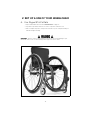 16
16
-
 17
17
-
 18
18
-
 19
19
-
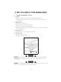 20
20
-
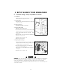 21
21
-
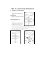 22
22
-
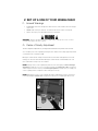 23
23
-
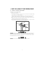 24
24
-
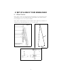 25
25
-
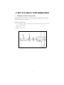 26
26
-
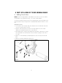 27
27
-
 28
28
-
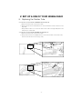 29
29
-
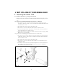 30
30
-
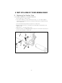 31
31
-
 32
32
-
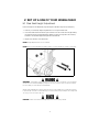 33
33
-
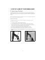 34
34
-
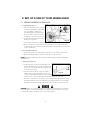 35
35
-
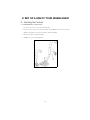 36
36
-
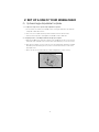 37
37
-
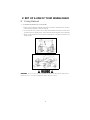 38
38
-
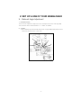 39
39
-
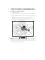 40
40
-
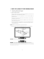 41
41
-
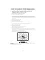 42
42
-
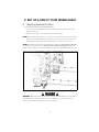 43
43
-
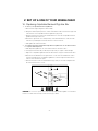 44
44
-
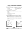 45
45
-
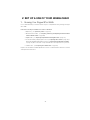 46
46
-
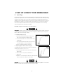 47
47
-
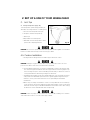 48
48
-
 49
49
-
 50
50
-
 51
51
-
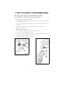 52
52
-
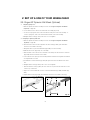 53
53
-
 54
54
-
 55
55
-
 56
56
-
 57
57
-
 58
58
-
 59
59
-
 60
60
-
 61
61
-
 62
62
-
 63
63
-
 64
64
-
 65
65
-
 66
66
-
 67
67
-
 68
68
-
 69
69
-
 70
70
-
 71
71
-
 72
72
-
 73
73
-
 74
74
-
 75
75
-
 76
76
-
 77
77
-
 78
78
-
 79
79
-
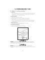 80
80
-
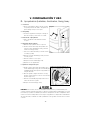 81
81
-
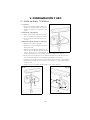 82
82
-
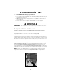 83
83
-
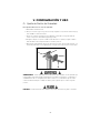 84
84
-
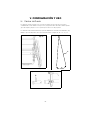 85
85
-
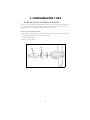 86
86
-
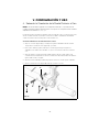 87
87
-
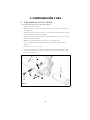 88
88
-
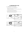 89
89
-
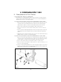 90
90
-
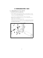 91
91
-
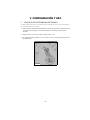 92
92
-
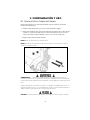 93
93
-
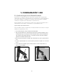 94
94
-
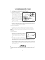 95
95
-
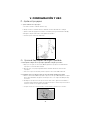 96
96
-
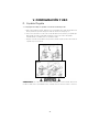 97
97
-
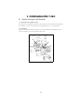 98
98
-
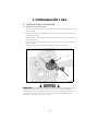 99
99
-
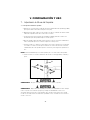 100
100
-
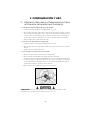 101
101
-
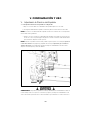 102
102
-
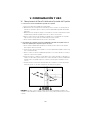 103
103
-
 104
104
-
 105
105
-
 106
106
-
 107
107
-
 108
108
-
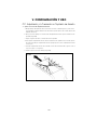 109
109
-
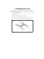 110
110
-
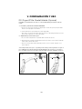 111
111
-
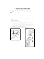 112
112
-
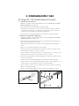 113
113
-
 114
114
-
 115
115
-
 116
116
-
 117
117
-
 118
118
-
 119
119
-
 120
120


Ki Mobility ROGUE XP User Instruction Manual & Warranty
- Tipo
- User Instruction Manual & Warranty
- Este manual también es adecuado para
En otros idiomas
- English: Ki Mobility ROGUE XP
Otros documentos
-
Home Decorators Collection CNF1599 Guía de instalación
-
Quickie EIR5 El manual del propietario
-
 Convaid EZ Rider Manual de usuario
-
-
Invacare Alu Lite Manual de usuario
-
Drive Medical Silver Sport 1 Wheelchair El manual del propietario
-
-
-
-
Insignia NS-HFMOC101 guía de instalación rápida
