
Betriebsanleitung | Operating instructions | Notice d’instruction
Istruzioni per l'uso | Instrucciones de servicio | Bruksanvisning
R412018457-BAL-001-AI
2021-06, Replaces: 2021-01
DE/EN/FR/IT/ES/SV
AVENTICS™ PM1
Elektromechanischer Druckschalter
Electromechanical pressure switch
Manostat électromécanique
Pressostato elettromeccanico
Presostato electromecánico
Elektromekanisk tryckvakt

AVENTICS™ PM1 | R412018457-BAL-001-AI | Deutsch 2
Inhaltsverzeichnis
1 Zu dieser Dokumentation.................................................................................................................................................................................................. 3
1.1 Zusätzliche Dokumentationen.......................................................................................................................................................................................... 3
1.2 Darstellung von Informationen ......................................................................................................................................................................................... 3
1.2.1 Warnhinweise .................................................................................................................................................................................................... 3
1.2.2 Symbole............................................................................................................................................................................................................. 3
2 Sicherheitshinweise........................................................................................................................................................................................................... 3
2.1 Bestimmungsgemäße Verwendung.................................................................................................................................................................................. 3
2.2 Qualifikation des Personals ............................................................................................................................................................................................... 3
2.3 Allgemeine Sicherheitshinweise........................................................................................................................................................................................ 3
2.3.1 Produkt- und technologieabhängige Sicherheitshinweise .................................................................................................................................. 3
3 Lieferumfang..................................................................................................................................................................................................................... 3
4 Zu diesem Produkt ............................................................................................................................................................................................................ 4
4.1 Produktbeschreibung ....................................................................................................................................................................................................... 4
4.2 Leistungsbeschreibung ..................................................................................................................................................................................................... 4
4.3 Übersicht Druckschalter Form A – pneumatischer Anschluss Flansch ................................................................................................................................ 4
4.4 Übersicht Druckschalter Form A – pneumatischer Anschluss Innengewinde G1/4............................................................................................................. 4
4.5 Übersicht Druckschalter M12x1 – pneumatischer Anschluss Flansch................................................................................................................................. 4
4.6 Übersicht Druckschalter M12x1 – pneumatischer Anschluss Innengewinde G1/4 ............................................................................................................. 4
4.7 Übersicht Druckschalter mit Steckanschluss ohne Leitungsdose - pneumatischer Anschluss Innengewinde G1/4............................................................. 4
4.8 Identifikation des Produkts ............................................................................................................................................................................................... 4
5 Montage............................................................................................................................................................................................................................ 4
5.1 Druckschalter montieren und pneumatisch anschließen................................................................................................................................................... 4
5.2 Druckschalter Form A elektrisch anschließen .................................................................................................................................................................... 4
5.3 Druckschalter M12x1 elektrisch anschließen..................................................................................................................................................................... 4
5.3.1 Vorschlag für Funkenlöschung ........................................................................................................................................................................... 4
6 Inbetriebnahme und Betrieb.............................................................................................................................................................................................. 5
6.1 Druckschalter in Betrieb nehmen ...................................................................................................................................................................................... 5
6.2 Schaltpunkt einstellen....................................................................................................................................................................................................... 5
7 Instandhaltung und Instandsetzung .................................................................................................................................................................................. 5
7.1 Reinigung ......................................................................................................................................................................................................................... 5
7.2 Wartung ........................................................................................................................................................................................................................... 5
8 Demontage und Austausch................................................................................................................................................................................................ 5
9 Entsorgung........................................................................................................................................................................................................................ 5
10 Fehlersuche und Fehlerbehebung...................................................................................................................................................................................... 5
10.1 Verhalten bei Störungen ................................................................................................................................................................................................... 5
11 Technische Daten .............................................................................................................................................................................................................. 5
12 Abbildungen...................................................................................................................................................................................................................... 6

1 Zu dieser Dokumentation
Lesen Sie diese Dokumentation vollständig und insbesondere das Kapitel „Sicher-
heitshinweise“ ,bevor Sie mit dem Produkt arbeiten.
Diese Anleitung enthält wichtige Informationen, um das Produkt sicher und sach-
gerecht zu montieren, zu bedienen, zu warten und einfache Störungen selbst zu
beseitigen.
1.1 Zusätzliche Dokumentationen
Neben dieser Dokumentation erhalten Sie weitere Unterlagen zum Produkt oder
zur Anlage bzw. Maschine, in die das Produkt eingebaut wird.
uAlle Unterlagen, die mit der Anlage oder Maschine mitgeliefert werden beach-
ten.
Zusätzlich immer folgende Vorschriften beachten:
• Allgemein gültige, gesetzliche und sonstige verbindliche Regelungen der eu-
ropäischen bzw. nationalen Gesetzgebung.
• Gültige Vorschriften zur Unfallverhütung und zum Umweltschutz.
1.2 Darstellung von Informationen
1.2.1 Warnhinweise
Warnungen vor Personen- und Sachschäden werden in dieser Dokumentation
besonders hervorgehoben. Die beschriebenen Maßnahmen zur Gefahrenabwehr
müssen eingehalten werden.
Darstellung als Hervorhebungskasten
Warnhinweise werden zum einen in Form von Hervorhebungskästen dargestellt
mit folgendem Aufbau:
SIGNALWORT
Art und Quelle der Gefahr
Folgen bei Nichtbeachtung
uMaßnahmen zur Gefahrenabwehr
Darstellung mit hervorgehobenem Signalwort
In Handlungsanweisungen und Auflistungen sind Warnhinweise oftmals in den
Text integriert. Sie werden mit einem fett hervorgehobenen Signalwort eingelei-
tet:
VORSICHT! Zulässige Biegeradien nicht überschreiten.
Bedeutung der Signalwörter
Signalwort Bedeutung
Warnung Möglicherweise drohende Gefahr für das Leben und die Gesundheit
von Personen.
Das Nichtbeachten dieser Hinweise kann schwere gesundheitliche
Auswirkungen zur Folge haben, bis hin zum Tod.
Vorsicht Möglicherweise gefährliche Situation.
Das Nichtbeachten dieser Hinweise kann leichte Verletzungen zur
Folge haben oder zu Sachbeschädigungen führen.
1.2.2 Symbole
Empfehlung für den optimalen Einsatz unserer Produkte.
Beachten Sie diese Informationen, um einen möglichst reibungslosen
Betriebsablauf zu gewährleisten.
2 Sicherheitshinweise
Das Produkt wurde gemäß den allgemein anerkannten Regeln der Technik her-
gestellt. Trotzdem besteht die Gefahr von Personen- und Sachschäden, wenn Sie
die folgenden grundsätzlichen Sicherheitshinweise und die Warnhinweise vor
Handlungsanweisungen in dieser Anleitung nicht beachten.
• Lesen Sie diese Anleitung gründlich und vollständig, bevor Sie mit dem Pro-
dukt arbeiten.
• Bewahren Sie die Anleitung so auf, dass sie jederzeit für alle Benutzer zugäng-
lich ist.
• Geben Sie das Produkt an Dritte stets zusammen mit der Betriebsanleitung
weiter.
2.1 Bestimmungsgemäße Verwendung
Das Produkt darf erst in Betrieb genommen werden, wenn es in die Maschine/die
Anlage, für die es bestimmt ist, eingebaut ist.
• Verwenden Sie den Druckschalter nur, um mittels Druckluft elektrische Kon-
takte zu öffnen und zu schließen.
• Verwenden Sie als Medium ausschließlich Druckluft bzw. Hydrauliköl.
• Halten Sie die in den technischen Daten genannten Betriebsbedingungen und
Leistungsgrenzen ein.
• Setzen Sie den Druckschalter ausschließlich im industriellen Bereich ein.
Die bestimmungsgemäße Verwendung schließt auch ein, dass Sie diese Anlei-
tung und insbesondere das Kapitel Sicherheitshinweise vollständig gelesen ha-
ben.
2.2 Qualifikation des Personals
Alle mit dem Produkt verbundenen Tätigkeiten erfordern grundlegende me-
chanische, pneumatische und elektrische Kenntnisse sowie Kenntnisse der zuge-
hörigen Fachbegriffe. Um die Betriebssicherheit zu gewährleisten, dürfen diese
Tätigkeiten daher nur von einer entsprechenden Fachkraft oder einer unterwiese-
nen Person unter Leitung einer Fachkraft durchgeführt werden.
Eine Fachkraft ist, wer aufgrund seiner fachlichen Ausbildung, seiner Kenntnisse
und Erfahrungen sowie seiner Kenntnisse der einschlägigen Bestimmungen die
ihm übertragenen Arbeiten beurteilen, mögliche Gefahren erkennen und geeig-
nete Sicherheitsmaßnahmen treffen kann. Eine Fachkraft muss die einschlägigen
fachspezifischen Regeln einhalten.
2.3 Allgemeine Sicherheitshinweise
• Beachten Sie die gültigen Vorschriften zur Unfallverhütung und zum Umwelt-
schutz im Verwenderland und am Arbeitsplatz.
• Verwenden Sie AVENTICS Produkte nur in technisch einwandfreiem Zustand.
• Prüfen Sie das Produkt auf offensichtliche Mängel, wie beispielsweise Risse im
Gehäuse oder fehlende Schrauben, Abdeckkappen, Dichtungen.
• Sie dürfen das Produkt grundsätzlich nicht verändern oder umbauen. Die Ge-
währleistung erlischt bei fehlerhafter Montage.
• Warnungen und Angaben zum Produkt dürfen nicht mit Farbe etc. überdeckt
werden, sondern müssen stets gut lesbar sein.
2.3.1 Produkt- und technologieabhängige Sicherheitshinweise
• Verlegen Sie die Kabel und Leitungen so, dass diese nicht beschädigt werden
und niemand darüber stolpern kann.
• Betreiben Sie das Produkt nicht in aggressiver Umgebungsluft (z. B. Lösungs-
mitteldämpfe).
• Setzen Sie das Produkt nicht in spritzwassergefährdeten Umgebungen ein.
• Der Betrieb in explosionsgefährdeter Umgebung ist nicht zulässig. Es besteht
Brand- und Explosionsgefahr!
• Das Produkt darf weder mit flüssigen noch mit dampfförmigen Stoffen in Be-
rührung kommen, die es angreifen. Zu diesen Stoffen zählen Benzol, Azeton,
Nitrodämpfe und Flüssigkeiten, die Weichmacher enthalten.
• Betreiben Sie das Produkt ausschließlich im Bereich der zugelassenen Be-
triebsspannung.
Die M12x1 Versionen nur über Netzgeräte mit Schutzkleinspannung (PELV)
und sicherer elektrischer Trennung der Betriebsspannung gemäß EN 60204
und für Form A Versionen gemäß EN 175301-803 bis 250 V.
• Die Montage im Freien darf nur bei ausreichendem Schutz gegen kritische
Umgebungsbedingungen wie aggressive oder salzhaltige Atmosphäre, starke
Temperaturschwankungen etc. erfolgen.
3 Lieferumfang
• 1x Elektromechanischer Druckschalter, Form A oder M12x1
• 1x Leitungsdose, je nach Ausführung (nur bei Form A)
• 2x Befestigungsschraube, bei Flanschausführung (CNOMO ohne Befesti-
gungsschrauben)
• 1x O-Ring, bei Flanschausführung (CNOMO ohne O-Ring)
• 1x Betriebsanleitung
AVENTICS™ PM1 | R412018457-BAL-001-AI | Deutsch 3

4 Zu diesem Produkt
4.1 Produktbeschreibung
Der Druckschalter wird verwendet, um bei Erreichen eines zuvor eingestellten
Druckwertes einen elektrischen Kontakt zu öffnen bzw. zu schließen.
4.2 Leistungsbeschreibung
Der Druckschalter wird am Anschluss G1/4 bzw. am Flansch mit einem entspre-
chenden Medium beaufschlagt. Bei Erreichen des eingestellten Schaltdrucks be-
tätigt eine Membran über eine Mechanik einen Mikroschalter (Umschalter).
Der Kontakt wechselt (siehe gAbb.6 und gAbb.7)
• bei steigendem Druck von 1-2 nach 1-3 (Form A)/von 1-2 nach 1-4 (M12x1) -
schließend
• bei fallendem Druck von 1-3 bzw. nach 1-2 (Form A)/von 1-4 nach 1-2
(M12x1) - öffnend
Für Vakuumdruckschalter (siehe gAbb.8 und gAbb.9)
• bei steigendem Vakuum von 1–3 nach 1-2 (Form A)/von 1–4 nach 1–2
(M12x1) - (schließend)
• bei fallendem Vakuum von 1–2 nach 1–3 (Form A)/von 1–2 nach 1–4
(M12x1)/ - (öffnend)
4.3 Übersicht Druckschalter Form A – pneumatischer An-
schluss Flansch
Siehe gAbb.1
1O-Ring ø 5x1,5
(außer bei CNOMO-Ausführung im
Lieferumfang enthalten)
2Leitungsdose (je nach Ausführung)
3Leitungsdose Zentralschraube
M3x35; MA=0,4+0,1Nm
(je nach Lieferumfang)
4Zylinderschraube M5x30 ISO1207
(2x); MA=2,5+0,5Nm (außer bei CNO-
MO-Ausführung im Lieferumfang
enthalten)
5Einstellschraube zur Feineinstellung,
selbsthaltend
(Bei CNOMO ist die Einstellschraube
fest eingestellt und mit Siegellack ge-
sichert)
4.4 Übersicht Druckschalter Form A – pneumatischer An-
schluss Innengewinde G1/4
Siehe gAbb.2
1Leitungsdose (je nach Ausführung) 2Anschluss G1/4, MA=12+1Nm
3Leitungsdose Zentralschraube
M3x35; MA=0,4+0,1Nm
(je nach Lieferumfang)
4Einstellschraube zur Feineinstellung,
selbsthaltend
4.5 Übersicht Druckschalter M12x1 – pneumatischer An-
schluss Flansch
Siehe gAbb.3
1O-Ring ø 5x1,5 (im Lieferumfang ent-
halten)
2Zylinderschraube M5x30 ISO 1207
(2x); MA = 2,5+0,5 Nm (im Lieferum-
fang enthalten)
3M12 Anschluss um 90° drehbar und je
30° rastbar, A-Kodierung
4Einstellschraube zur Feineinstellung,
selbsthaltend
4.6 Übersicht Druckschalter M12x1 – pneumatischer An-
schluss Innengewinde G1/4
Siehe gAbb.4
1M12 Anschluss um 90° drehbar und je
30° rastbar, A-Kodierung
2Anschluss G1/4, MA=12+1Nm
3Einstellschraube zur Feineinstellung,
selbsthaltend
INFO: Die Materialnummern entnehmen Sie bitte dem Online-Katalog.
4.7 Übersicht Druckschalter mit Steckanschluss ohne Lei-
tungsdose - pneumatischer Anschluss Innengewinde
G1/4
Siehe gAbb.5
1Steckanschluss 2Anschluss G1/4, MA=12+1Nm
3Gewinde für Zentralschraube M3x35
Zulässiges Anzugsdrehmoment
MA= 0,4 +0,1 Nm
4Einstellschraube zur Feineinstellung,
selbsthaltend
4.8 Identifikation des Produkts
uBeachten Sie die Produktangaben auf dem Produkt und der Verpackung.
5 Montage
uLassen Sie das Produkt vor der Inbetriebnahme einige Stunden akklimatisie-
ren, da sich ansonsten im Gehäuse Kondenswasser niederschlagen kann.
VORSICHT
Verletzungsgefahr durch Montage unter Druck oder Spannung!
Die Montage unter Druck oder anliegender elektrischer Spannung kann zu Ver-
letzungen führen und das Produkt oder Anlagenteile beschädigen.
1. Schalten Sie den relevanten Anlagenteil drucklos und spannungsfrei, bevor
Sie das Produkt montieren.
2. Sichern Sie die Anlage gegen Wiedereinschalten.
5.1 Druckschalter montieren und pneumatisch anschließen
1. Schalten Sie die Anlage drucklos und spannungsfrei.
2. Verbinden Sie den Druckschalter mit dem Drucksystem:
- Anschluss G1/4: MA=12+1Nm
- Flanschanschluss M5: MA=2,5+0,5Nm
5.2 Druckschalter Form A elektrisch anschließen
Siehe gAbb.10
uVerwenden Sie nur Anschlussleitungen, die die erforderliche Lei-
tungsqualität und den Durchmesser der Kabelverschraubung von 6
- 8 mm besitzen.
uVerwenden Sie bei Umgebungstemperaturen von > 70°C ein ent-
sprechend temperaturbeständiges Kabel.
1. Demontieren Sie die Leistungsdose.
2. Verbinden Sie den Anschluss mit den Schraubklemmen (MA=0,4Nm).
Die Klemmen sind für Querschnitte bis 1,5mm2 ausgelegt.
3. Schließen Sie den Schutzleiter an.
4. Klemmen Sie die Leitungsdose an.
5. Stellen Sie sicher, dass die Kabelverschraubung am Stecker montiert ist, um
die Schutzart IP65 sicherzustellen (MA=1,8Nm+0,2Nm).
6. Montieren Sie die Leitungsdose sorgfältig am Druckschalter, um die Schutzart
IP65 sicherzustellen (MA=0,4Nm+0,1Nm).
5.3 Druckschalter M12x1 elektrisch anschließen
Siehe gAbb.11
uBetreiben Sie den Druckschalter nur in einem Stromkreis mit siche-
rer Trennung vom Netz (PELV nach DINVDE0100-410,
IEC364-4-43, HD384.4.41S2, EN60079-14). Der Stromkreis muss
potentialfrei (nicht geerdet) sein.
Elektrischer Anschluss am Druckschalter M12x1 – Pinbelegung
Pin 1 2 3 4
Farbe Braun (BN) Weiss (WH) Blau (BU) Schwarz (BK)
INFO: Das Kabel ist nicht im Lieferumfang enthalten.
Gehen Sie beim Anschließen wie folgt vor:
1. Schrauben Sie das Kabel auf den Rundsteckverbinder.
2. Ziehen Sie die Rändelmutter des Rundsteckverbinder handfest an (die Ras-
tung ist spürbar/hörbar).
5.3.1 Vorschlag für Funkenlöschung
Schutzschaltung Gleichspannung
Siehe gAbb.12
uSchließen Sie die Diode (G) parallel zur Last (Verbraucher) (F) an.
AVENTICS™ PM1 | R412018457-BAL-001-AI | Deutsch 4

Beim Anschluss der Diode auf die richtige Polarität achten! Auswahlbe-
dingung für die Diode: UDiode≥ 1,4xUNetz; IDiode≥ILast
Schutzschaltung Wechselspannung
Siehe gAbb.13
uSchließen Sie das RC-Glied (E) parallel zur Last (Verbraucher) (F) an.
Richtwert für die RC-Auswahl: R[Ω]~0,2RLast[Ω]; C[µF]~ILast[Α]
Es dürfen keine Elektrolytkondensatoren verwendet werden!
6 Inbetriebnahme und Betrieb
WARNUNG
Verletzungsgefahr durch unkontrollierte Bewegungen der Aktoren beim
Einschalten der Pneumatik!
Es besteht Verletzungsgefahr, wenn sich das System in einem undefinierten
Zustand befindet.
uBringen Sie das System in einen definierten Zustand, bevor Sie es einschal-
ten!
VORSICHT
Anlage steht im Betrieb unter Druck!
Bei unsachgemäßer Installation kann es zur Beschädigung des Produkts und
schweren Verletzungen kommen.
uVor Inbetriebnahme alle Verbindungen, Anschlüsse und Wartungsgeräte
auf korrekte Installation prüfen.
6.1 Druckschalter in Betrieb nehmen
Zur Inbetriebnahme des Druckschalters gehen Sie wie folgt vor:
1. Prüfen Sie, ob der Druckschalter richtig montiert ist (siehe Kapitel „g5.Mon-
tage“ und „g2.Sicherheitshinweise“) und stellen Sie sicher, dass alle An-
schlüsse des Druckschalters korrekt verbunden sind.
2. Sichern Sie die zu schaltenden Komponenten vor unbeabsichtigten Reaktio-
nen und legen Sie Spannung an.
3. Beaufschlagen Sie die Anlage mit Druckluft.
4. Überprüfen Sie die Schaltausgänge auf ordnungsgemäße Funktion.
6.2 Schaltpunkt einstellen
Siehe gAbb.14
Stellen Sie den Schaltpunkt auf einen höheren Druck ein, indem Sie die Einstell-
schraube (1) nach rechts drehen (+). Drehmoment für Einstellschraube max.
1Nm.
1. Die Einstellschraube ist selbsthaltend und bleibt auch bei ungünstigen Einsät-
zen, ohne zusätzliche Sicherung, in der eingestellten Position.
Stellen Sie den Schaltpunkt auf einen geringeren Druck ein, indem Sie die Ein-
stellschraube (1) nach links drehen (–).
Angaben zur Werkseinstellung: siehe Online-Katalog und Typenschild.
2. Kontrollieren Sie den Einstellwert (Schaltpunkt) mit einem externen Manome-
ter.
INFO: Der Schaltpunkt ist stufenlos einstellbar, auch während des Betriebes.
Die Bereichsauswahl ist optimal, wenn der Schaltpunkt mittig im Schaltdruck-
bereich liegt. Optional kann ein Manometer zu Hilfe genommen werden.
7 Instandhaltung und Instandsetzung
7.1 Reinigung
Das Produkt muss regelmäßig gereinigt werden.
• Keine Hochdruckreiniger verwenden.
• Niemals Lösemittel oder aggressive Reinigungsmittel verwenden.
• Produkt ausschließlich mit einem leicht feuchten Tuch reinigen und aus-
schließlich Wasser und ggf. ein mildes Reinigungsmittel verwenden.
7.2 Wartung
Das Produkt ist wartungsfrei. Bei technischen Problemen wenden Sie sich bitte an
eine der Kontaktadressen unter www.emerson.com/contactus.
8 Demontage und Austausch
VORSICHT
Verletzungsgefahr durch Montage unter Druck oder Spannung!
Die Montage unter Druck oder anliegender elektrischer Spannung kann zu Ver-
letzungen führen und das Produkt oder Anlagenteile beschädigen.
1. Schalten Sie den relevanten Anlagenteil drucklos und spannungsfrei, bevor
Sie das Produkt montieren.
2. Sichern Sie die Anlage gegen Wiedereinschalten.
1. Schalten Sie die Anlage drucklos und spannungsfrei.
2. Lösen und entfernen Sie den Rundsteckverbinder.
3. Lösen Sie die Befestigungsschrauben des Druckschalters.
4. Entfernen Sie den Druckschalter vom Drucksystem.
9 Entsorgung
Entsorgen Sie das Produkt nach den nationalen Bestimmungen Ihres Landes.
10 Fehlersuche und Fehlerbehebung
Falls Sie den aufgetretenen Fehler nicht beheben konnten, wenden Sie sich bitte
an eine der Kontaktadressen unter www.emerson.com/contactus.
10.1 Verhalten bei Störungen
uTauschen Sie bei Störungen mit unbekannter Ursache den Druckschalter ge-
gen einen Original-Druckschalter aus.
Einzelne Bauteile des Druckschalters können nicht ersetzt oder repa-
riert werden.
Falls Sie den aufgetretenen Fehler nicht beheben konnten, wenden Sie sich bitte
an eine der Kontaktadressen unter www.emerson.com/contactus.
11 Technische Daten
Dieses Kapitel enthält einen Auszug der wichtigsten Technischen Daten. Weitere
Technische Daten finden Sie im Online-Katalog.
Allgemein
Spezifikation
Umgebungstempera-
tur
min. …max.
-20°C…+80°C
UL-Applikation:
Umgebungstempera-
tur max.
+75°C
Pneumatik
Spezifikation
Medium Druckluft nach ISO8573-1:2010, (max. Partikelgröße: 40µm; Druck-
taupunkt: ≤3°C; Ölgehalt: max. 40mg/m3) Hydrauliköl
Schaltdruckbereich -0,9…0bar / -0,9…3bar / 0,2…16bar
Elektrik
Spezifikation
Betriebsspannung
min.…max. Form A
12V…125VDC; 12V…250VAC
Betriebsspannung
min.…max. M12x1
12V…30VDC/VAC
AVENTICS™ PM1 | R412018457-BAL-001-AI | Deutsch 5

Schaltvermögen
Schaltspannung [VAC]
30 48 60 125 250
Typ Stromart Belastungsart max. Schaltstrom [A] 1)
Form A AC Ohmsche Last 5 5 5 5 5
Induktive Last 2) 33333
DC Ohmsche Last 3 1,2 0,8 0,4
Induktive Last 2) 2 0,55 0,4 0,05
M12x1 AC Ohmsche Last 4
Induktive Last 2) 3
DC Ohmsche Last 3
Induktive Last 2) 2
1) Bezugsschaltzahl 30/min. Bezugstemperatur +30°C, M12x1, U=30V
2) Induktive Last: AC=cos~0,7°; DC=L/R~10ms
Elektrische Nennwerte gemäß UL 508 und CSA C22.2 NO. 14-18
Typ Maximaler
Schaltstrom
Verdrahtung
im Feld bei Kabel-Ø
6–8mm
Anzugsmoment
[Nm]
Form A 5A, 250VAC, GP 20-14 AWG Str. 0,4
M12x1 4A, 30VAC, GP - -
12 Abbildungen
Abbildungen: Ansicht variiert je nach Serie.
21
10
30
4,2
0,3
0,2
0,3
3,8
1,5
max. 76
68,1
0,3
ca. 76
5
0,3
20
10
30
5,2
0,3
0,3
0,3
0,3
5
1,3
0,5
30
0,3
40
M16x1,5
1,15 0,05
7,9
5
2
2)
3) 5)
1)
CNOMO
4)
Abb.1: Form A, pneumatischer Anschluss Flansch
M16x1,5
20
15
30 ISO 228
max. 76
5,2
12
73,1
0,3
2
0,5
ca. 81
45
30
9,6
90
13,5
5
2
G1/4
0,3
0,3
5
0,3
0,3
0,2
0,3
2)
1)
3)
4)
Abb.2: Form A, Innengewinde G 1/4
20
10
30 43,5
5,2
68,1
0,3
0,3
0,3
5
0,3
0,3
0,3
5
1,3
0,5
1,15
0,05
7,9
30
0,3
5
2
9,6
M12x1
30
58,6
40
1)
2)
3)
4)
Abb.3: M12x1, pneumatischer Anschluss Flansch
AVENTICS™ PM1 | R412018457-BAL-001-AI | Deutsch 6

20
15
30 ISO 228
43,5
58,6
5,2
9,6
5
2
G1/4
0,3
0,3
5
0,3
0,3
0,2
45
M12x1
45
12
73,1
0,3
2
0,5
30
0,3
2)
1) 3)
Abb.4: M12x1, pneumatischer Anschluss, Innengewinde G 1/4
20
15
30 ISO 228
5,2
12
73,1
0,3
2
0,5
30
9,6
45
5
2
G1/4
0,3
0,3
5
0,3
0,3
0,2
0,3
43,7
45
90
13,5
45
90
13,5
12
73,1
0,3
2
0,5
30
45
0,3
ISO 228
9,6
G1/4
5
0,3
39
3
3
1
4
1
2
2
nur für R412010633
Abb.5: Steckanschluss ohne Leitungsdose, Innengewinde G 1/4
2
1
3
Abb.6: Form A: Schaltfunktionen
Druckschalter
2
1
4
Abb.7: M12x1: Schaltfunktionen
Druckschalter
1
23
Abb.8: Form A: Schaltfunktionen Vaku-
umschalter
1
24
Abb.9: M12x1: Schaltfunktionen Vaku-
umschalter
1
2
3
4
1+UB
2Öffner
3Schließer
4GND
Abb.10: Pin-Belegung für Leitungsdose: Form A
34
1
2
1+UB
2Öffner
3Keine Funktion
4Schließer
Abb.11: Pin-Belegung für Leitungsdose: M12x1
1
23
G
F
Abb.12: Funkenlöschung Gleichspan-
nung
1
23
E
F
Abb.13: Funkenlöschung Wechsel-
spannung
5
2
5
2
1
Abb.14: Schaltpunkt einstellen
AVENTICS™ PM1 | R412018457-BAL-001-AI | Deutsch 7

AVENTICS™ PM1 | R412018457-BAL-001-AI | English 8
Contents
1 About This Documentation................................................................................................................................................................................................ 9
1.1 Additional documentation................................................................................................................................................................................................ 9
1.2 Presentation of information .............................................................................................................................................................................................. 9
1.2.1 Warnings............................................................................................................................................................................................................ 9
1.2.2 Symbols ............................................................................................................................................................................................................. 9
2 Notes on Safety ................................................................................................................................................................................................................. 9
2.1 Intended use..................................................................................................................................................................................................................... 9
2.2 Personnel qualifications .................................................................................................................................................................................................... 9
2.3 General safety instructions................................................................................................................................................................................................ 9
2.3.1 Safety instructions related to the product and technology ................................................................................................................................. 9
3 Scope of Delivery............................................................................................................................................................................................................... 9
4 About This Product ............................................................................................................................................................................................................ 9
4.1 Product description........................................................................................................................................................................................................... 9
4.2 Performance specifications............................................................................................................................................................................................... 9
4.3 Overview of pressure switch form A – pneumatic flange connection................................................................................................................................. 10
4.4 Overview of pressure switch form A – pneumatic connection, internal thread G1/4.......................................................................................................... 10
4.5 Overview of pressure switch M12x1 – pneumatic flange connection................................................................................................................................. 10
4.6 Overview of pressure switch M12x1 – pneumatic connection, internal thread G1/4.......................................................................................................... 10
4.7 Overview of pressure switch with push-in fitting/without electrical connector – pneumatic connection, internal thread G1/4 ......................................... 10
4.8 Product identification ....................................................................................................................................................................................................... 10
5 Assembly........................................................................................................................................................................................................................... 10
5.1 Assembling the pressure switch and connecting the pneumatics...................................................................................................................................... 10
5.2 Electrically connecting pressure switch form A.................................................................................................................................................................. 10
5.3 Electrically connecting pressure switch M12x1.................................................................................................................................................................. 10
5.3.1 Suggestion for spark-quenching......................................................................................................................................................................... 10
6 Commissioning and Operation .......................................................................................................................................................................................... 11
6.1 Commissioning the pressure switch.................................................................................................................................................................................. 11
6.2 Setting the switching point ............................................................................................................................................................................................... 11
7 Service and Repairs............................................................................................................................................................................................................ 11
7.1 Cleaning............................................................................................................................................................................................................................ 11
7.2 Maintenance..................................................................................................................................................................................................................... 11
8 Disassembly and Exchange ................................................................................................................................................................................................ 11
9 Disposal............................................................................................................................................................................................................................. 11
10 Troubleshooting................................................................................................................................................................................................................ 11
10.1 Response to malfunctions................................................................................................................................................................................................. 11
11 Technical Data................................................................................................................................................................................................................... 11
12 Figures .............................................................................................................................................................................................................................. 12

1 About This Documentation
Read this documentation carefully, especially the section “Notes on Safety” , be-
fore working with the product.
These instructions contain important information on the safe and appropriate as-
sembly, operation, and maintenance of the product and how to remedy simple
malfunctions yourself.
1.1 Additional documentation
In addition to this documentation, you will obtain further documents on the
product or the machine/system where it is installed.
uObserve all documents supplied with the system or machine.
Additionally always observe the following regulations:
• General, statutory and other binding rules of the European and national laws.
• Applicable regulations for accident prevention and environmental protection.
1.2 Presentation of information
1.2.1 Warnings
Warnings of personal injury and damage to property are highlighted in this docu-
mentation. The measures described to avoid these hazards must be followed.
Display as highlighted box
Warnings are displayed in the form of highlighted boxes with the following struc-
ture:
SIGNAL WORD
Hazard type and source
Consequences
uPrecautions
Presentation with highlighted signal word
Instructions and lists often contain warnings that are integrated into the text.
They are introduced with a bold signal word:
CAUTION! Do not exceed permissible bending radii.
Meaning of the signal words
Signal word Meaning
Warning Possible danger to the life and health of persons.
Failure to observe these notices can result in serious health conse-
quences, including death.
Caution Possible dangerous situation.
Failure to observe these notices may result in minor injuries or dam-
age to property.
1.2.2 Symbols
Recommendation for the optimum use of our products.
Observe this information to ensure the smoothest possible operation.
2 Notes on Safety
The product has been manufactured according to the accepted rules of current
technology. Even so, there is a risk of injury or damage if the following general
safety instructions and the specific warnings given in this instruction manual are
not observed.
• Please read all these instructions carefully before working with the product.
• Keep these instructions in a location where they are accessible to all users at
all times.
• Always include the operating instructions when you pass the product on to
third parties.
2.1 Intended use
The product may only be commissioned after it has been installed in the ma-
chine/system for which it is intended.
• Only use the pressure switch to open and close electrical contacts using com-
pressed air.
• Only use compressed air or hydraulic oil as the medium.
• Use is permitted only under the operating conditions and within the perfor-
mance limits listed in the technical data.
• The pressure switch is only intended for industrial applications.
Intended use includes having read and understood these instructions completely,
especially the section “Notes on Safety”.
2.2 Personnel qualifications
All tasks associated with the product require basic mechanical, pneumatic and
electrical knowledge, as well as knowledge of the respective technical terms. In
order to ensure operational safety, these tasks may only be carried out by quali-
fied personnel or an instructed person under the direction of qualified personnel.
Qualifiedpersonnel are those who can recognize possible dangers and institute
the appropriate safety measures, due to their professional training, knowledge,
and experience, as well as their understanding of the relevant regulations per-
taining to the work to be done. Qualified personnel must observe the rules rele-
vant to the subject area.
2.3 General safety instructions
• Observe the valid local regulations to protect the environment in the country
of use and to avoid workplace accidents.
• Only use AVENTICS products that are in perfect working order.
• Examine the product for obvious defects, such as cracks in the housing or
missing screws, caps, or seals.
• Do not modify or convert the product. The warranty will not apply if the prod-
uct is incorrectly assembled.
• Product warnings and information must be legible, i.e. not covered by paint,
etc.
2.3.1 Safety instructions related to the product and technology
• Lay cables and lines so that they cannot be damaged and no one can trip over
them.
• Do not operate the product in aggressive ambient air (e.g., solvent vapors).
• Do not use the product in environments that are not splashwater-proof.
• Operation in an explosive atmosphere is not permissible. There is a danger of
fires and explosions!
• The product may not come into contact with aggressive substances in liquid
or vapor form. These substances include benzene, acetone, nitro vapors, and
liquids containing softeners.
• Only operate the product within the approved operating voltage range.
Only operate M12x1 versions via power packs with protective extra-low volt-
age (PELV) and secure electrical isolation from the operating voltage in accor-
dance with EN60204, and form A versions in accordance with EN175301-803
up to 250V.
• Assembly outdoors is only permitted if there is sufficient protection against
critical ambient conditions such as an aggressive or salty atmosphere, large
fluctuations in temperature, etc.
3 Scope of Delivery
• 1x electromechanical pressure switch, form A or M12x1
• 1x electrical connector, depending on the version (only for form A)
• 2x mounting screw, for flange version (CNOMO without mounting screws)
• 1x O-ring, for flange version (CNOMO without O-ring)
• 1x Operating instructions
4 About This Product
4.1 Product description
The pressure switch is used to open or close an electrical contact when a preset
pressure value is reached.
4.2 Performance specifications
An appropriate medium is applied to the pressure switch at the G1/4 connection
or on the flange. A diaphragm actuates a microswitch (change-over switch) via a
mechanism once the preset switching pressure is reached.
AVENTICS™ PM1 | R412018457-BAL-001-AI | English 9

The contact switches (see gFig.6 and gFig.7)
• when pressure increases from 1-2 to 1-3 (form A)/from 1-2 to 1-4 (M12x1) -
make contact (NO)
• on decreasing pressure from 1-3 to 1-2 (form A)/from 1-4 to 1-2 (M12x1) -
break contact (NC)
For vacuum pressure switches (see gFig.8 and gFig.9)
• when the vacuum increases from 1-3 to 1-2 (form A)/from 1-4 to 1-2 (M12x1)
- make contact (NO)
• on decreasing vacuum from 1-2 to 1-3 (form A)/from 1-2 to 1-4 (M12x1) -
break contact (NC)
4.3 Overview of pressure switch form A – pneumatic flange
connection
See gFig.1
1O-ring ø 5x1.5
(included in scope of delivery except
for CNOMO version)
2Electrical connector (depending on
version)
3Electrical connector central screw
M3x35; MA=0.4+0.1Nm
(depending on scope of delivery)
4Cylinder screw M5x30 ISO1207 (2x);
MA=2.5+0.5Nm (included in scope of
delivery except for CNOMO version)
5Adjustment screw for fine adjust-
ment, self-holding
(the adjustment screw is perma-
nently set in the CNOMO version and
secured with sealing compound)
4.4 Overview of pressure switch form A – pneumatic connec-
tion, internal thread G1/4
See gFig.2
1Electrical connector (depending on
version)
2Connection G1/4, MA=12+1Nm
3Electrical connector central screw
M3x35; MA=0.4+0.1Nm
(depending on scope of delivery)
4Adjustment screw for fine adjust-
ment, self-holding
4.5 Overview of pressure switch M12x1 – pneumatic flange
connection
See gFig.3
1O-ring ø 5x1.5 (included in scope of
delivery)
2Cylinder screw M5x30 ISO1207 (2x);
MA=2.5+0.5Nm (included in scope
of delivery)
3M12 connection rotatable by 90° and
30° with detent, A-coding
4Adjustment screw for fine adjust-
ment, self-holding
4.6 Overview of pressure switch M12x1 – pneumatic connec-
tion, internal thread G1/4
See gFig.4
1M12 connection rotatable by 90° and
30° with detent, A-coding
2Connection G1/4, MA=12+1Nm
3Adjustment screw for fine adjust-
ment, self-holding
INFO: For material numbers, please refer to the online catalog.
4.7 Overview of pressure switch with push-in fitting/without
electrical connector – pneumatic connection, internal
thread G1/4
See gFig.5
1Push-in fitting 2Connection G1/4, MA=12+1Nm
3Thread for central screw M3x35
Permissible tightening torque
MA=0.4+0.1Nm
4Adjustment screw for fine adjust-
ment, self-holding
4.8 Product identification
uObserve the product information on the product and packaging.
5 Assembly
uLet the product acclimatize for several hours before commissioning, other-
wise, water may condense in the housing.
CAUTION
Danger of injury if assembled under pressure or voltage!
Assembling when under pressure or electrical voltage can lead to injuries and
damage to the product or system components.
1. Make sure that the relevant system component is not under voltage or
pressure before you assemble the product.
2. Protect the system against being restarted.
5.1 Assembling the pressure switch and connecting the
pneumatics
1. Make sure that the system is not under voltage or pressure.
2. Connect the pressure switch with the pressure system:
- Connection G1/4: MA=12+1Nm
- Flange connection M5: MA=2.5+0.5Nm
5.2 Electrically connecting pressure switch form A
See gFig.10
uOnly use connection cables which fulfill the required cable quality
and the cable fitting diameter of 6 – 8 mm.
uUse a suitable temperature-resistant cable with ambient tempera-
tures of>70°C.
1. Disassemble the electrical connector.
2. Fit the connection with the screw terminals (MA=0.4Nm).
The terminals are intended for cross-sections of up to 1.5mm2.
3. Connect the protective conductor.
4. Connect the electrical connector.
5. Check that the cable fitting is mounted to the plug to ensure the IP65 protec-
tion class (MA=1.8Nm+0.2Nm).
6. Carefully mount the electrical connector to the pressure switch to ensure the
IP65 protection class (MA=0.4Nm+0.1Nm).
5.3 Electrically connecting pressure switch M12x1
See gFig.11
uOnly operate the pressure switch in an electrical circuit with safe
isolation from the mains (PELV in acc. with DINVDE0100-410,
IEC364-4-43, HD384.4.41S2, EN60079-14). The electrical circuit
must be potential-free (not grounded).
Electrical connection on pressure switch M12x1 – pin assignments
Pin 1 2 3 4
Color Brown (BN) White (WH) Blue (BU) Black (BK)
INFO: The cable is not included in the scope of delivery.
Proceed as follows for connection:
1. Thread the cable onto the round plug connector.
2. Hand tighten the knurled nut on the round plug connector (audible/tactile en-
gagement).
5.3.1 Suggestion for spark-quenching
DC voltage protective circuit
See gFig.12
uConnect the diode (G) parallel to the load (consumer) (F).
Pay attention to the correct polarity when connecting the diode! Se-
lection criteria for the diode: UDiode≥ 1.4xUMains; IDiode≥ILoad
AC voltage protective circuit
See gFig.13
uConnect the RC element (E) parallel to the load (consumer) (F).
AVENTICS™ PM1 | R412018457-BAL-001-AI | English 10

Guide value for RC selection: R[Ω]~0.2RLoad[Ω]; C[µF]~ILoad[A]
Do not use electrolytic capacitors!
6 Commissioning and Operation
WARNING
Risk of injury due to uncontrolled actuator movements when the pneumat-
ics are switched on!
There is a danger of personal injury if the system is in an undefined state.
uPut the system in a defined state before switching it on.
CAUTION
System is operating under pressure!
Incorrect installation could damage the product and cause serious injury.
uBefore commissioning, check that all connections, ports and maintenance
equipment have been correctly installed.
6.1 Commissioning the pressure switch
Proceed as follows to commission the pressure switch:
1. Check whether the pressure switch is mounted correctly (see sec-
tions"g5.Assembly" and "g2.Notes on Safety") and make sure that all pres-
sure switch connections are properly connected.
2. Secure the components to be switched to prevent unintentional responses,
and apply voltage.
3. Apply the compressed air to the system.
4. Check that the switch outputs are functioning properly.
6.2 Setting the switching point
See gFig.14
Increase the switching point pressure by turning the adjustment screw (1) to the
right (+). Max. torque for adjustment screw 1Nm.
1. The adjustment screw is self-holding and also remains in the set position with-
out any additional securing, even under unfavorable circumstances.
Reduce the switching point pressure by turning the adjustment screw (1) to
the left (–).
Information on factory settings: see online catalog and name plate.
2. Use an external pressure gauge to check the setting value (switching point).
INFO: The switching point is continuously adjustable, even during operation.
The optimum selection range is when the switching point is in the middle of
the switching pressure range. Optionally, a pressure gauge can be used as an
aid.
7 Service and Repairs
7.1 Cleaning
The product must be cleaned at regular intervals.
• Do not use high-pressure cleaners for cleaning!
• Never use solvents or aggressive detergents!
• Clean the product only with a cloth slightly moistened with water or a mild de-
tergent!
7.2 Maintenance
The product is maintenance-free. In case of technical problems, please contact
one of the addresses found under www.emerson.com/contactus.
8 Disassembly and Exchange
CAUTION
Danger of injury if assembled under pressure or voltage!
Assembling when under pressure or electrical voltage can lead to injuries and
damage to the product or system components.
1. Make sure that the relevant system component is not under voltage or
pressure before you assemble the product.
2. Protect the system against being restarted.
1. Make sure that the system is not under voltage or pressure.
2. Release and remove the round plug connector.
3. Loosen the mounting screws on the pressure switch.
4. Remove the pressure switch from the pressure system.
9 Disposal
Dispose of the product in accordance with the national regulations in your coun-
try.
10 Troubleshooting
If you cannot remedy a malfunction, please contact one of the addresses found
under www.emerson.com/contactus.
10.1 Response to malfunctions
uIf malfunctions occur with unknown causes, exchange the pressure switch
with an original pressure switch.
The individual components of the pressure switch cannot be replaced
or repaired.
If you cannot remedy a malfunction, please contact one of the addresses found
under www.emerson.com/contactus.
11 Technical Data
This section contains an excerpt of the key technical data. Further technical data
can be found in the online catalog.
General
Specifications
Ambient temperature
min.–max
-20–+80°C
UL application:
Max. ambient tem-
perature
+75°C
Pneumatics
Specifications
Medium Compressed air in accordance with ISO8573-1:2010, (max. particle
size: 40µm; medium dew point: ≤3°C; oil content: max. 40mg/m3)
hydraulic oil
Operating pressure
range
-0.9–0bar / -0.9–3bar / 0.2–16bar
Electrics
Specifications
Operating voltage
min.–max., form A
12V–125VDC; 12V–250VAC
Operating voltage
min.–max., M12x1
12V–30VDC/VAC
AVENTICS™ PM1 | R412018457-BAL-001-AI | English 11

Switching capacity
Switching voltage [VAC]
30 48 60 125 250
Type Current
type
Load type Max. switching current [A] 1)
Form A AC Resistive load 5 5 5 5 5
Inductive load 2) 33333
DC Resistive load 3 1.2 0.8 0.4
Inductive load 2) 2 0.55 0.4 0.05
M12x1 AC Resistive load 4
Inductive load 2) 3
DC Resistive load 3
Inductive load 2) 2
1) Reference cycle: 30/min., reference temperature: +30°C, M12x1, U=30V
2) Inductive load: AC=cos~0.7°; DC=L/R~10ms
Electrical nominal values according to UL 508 and CSA C22.2 NO.
14-18
Type Maximum
switching current
Wiring
in the field with ca-
ble Ø 6–8mm
Tightening torque
[Nm]
Form A 5A, 250VAC, BP 20-14 AWG ctrl. 0.4
M12x1 4A, 30VAC, BP - -
12 Figures
Figures: View varies according to the series.
21
10
30
4,2
0,3
0,2
0,3
3,8
1,5
max. 76
68,1
0,3
ca. 76
5
0,3
20
10
30
5,2
0,3
0,3
0,3
0,3
5
1,3
0,5
30
0,3
40
M16x1,5
1,15 0,05
7,9
5
2
2)
3) 5)
1)
CNOMO
4)
Fig.1: Form A, pneumatic flange connection
M16x1,5
20
15
30 ISO 228
max. 76
5,2
12
73,1
0,3
2
0,5
ca. 81
45
30
9,6
90
13,5
5
2
G1/4
0,3
0,3
5
0,3
0,3
0,2
0,3
2)
1)
3)
4)
Fig.2: Form A, internal thread G1/4
20
10
30 43,5
5,2
68,1
0,3
0,3
0,3
5
0,3
0,3
0,3
5
1,3
0,5
1,15
0,05
7,9
30
0,3
5
2
9,6
M12x1
30
58,6
40
1)
2)
3)
4)
Fig.3: M12x1, pneumatic flange connection
AVENTICS™ PM1 | R412018457-BAL-001-AI | English 12

20
15
30 ISO 228
43,5
58,6
5,2
9,6
5
2
G1/4
0,3
0,3
5
0,3
0,3
0,2
45
M12x1
45
12
73,1
0,3
2
0,5
30
0,3
2)
1) 3)
Fig.4: M12x1, pneumatic connection, internal thread G1/4
20
15
30 ISO 228
5,2
12
73,1
0,3
2
0,5
30
9,6
45
5
2
G1/4
0,3
0,3
5
0,3
0,3
0,2
0,3
43,7
45
90
13,5
45
90
13,5
12
73,1
0,3
2
0,5
30
45
0,3
ISO 228
9,6
G1/4
5
0,3
39
3
3
1
4
1
2
2
only for R412010633
Fig.5: Push-in fitting without electrical connector, internal thread G1/4
2
1
3
Fig.6: Form A: Pressure switch switch-
ing functions
2
1
4
Fig.7: M12x1: Pressure switch switch-
ing functions
1
23
Fig.8: Form A: Vacuum switch switch-
ing functions
1
24
Fig.9: M12x1: Vacuum switch switch-
ing functions
1
2
3
4
1+UB
2Break contact (NC)
3Make contact (NO)
4GND
Fig.10: PIN assignment for electrical connector: Form A
34
1
2
1+UB
2Break contact (NC)
3No function
4Make contact (NO)
Fig.11: PIN assignment for electrical connector: M12x1
1
23
G
F
Fig.12: Spark quenching, DC voltage
1
23
E
F
Fig.13: Spark quenching, AC voltage
5
2
5
2
1
Fig.14: Setting the switching point
AVENTICS™ PM1 | R412018457-BAL-001-AI | English 13

AVENTICS™ PM1 | R412018457-BAL-001-AI | Français 14
Sommaire
1 A propos de cette documentation...................................................................................................................................................................................... 15
1.1 Documentations complémentaires................................................................................................................................................................................... 15
1.2 Présentation des informations .......................................................................................................................................................................................... 15
1.2.1 Mises en garde ................................................................................................................................................................................................... 15
1.2.2 Symboles ........................................................................................................................................................................................................... 15
2 Consignes de sécurité ........................................................................................................................................................................................................ 15
2.1 Utilisation conforme ......................................................................................................................................................................................................... 15
2.2 Qualification du personnel ................................................................................................................................................................................................ 15
2.3 Consignes générales de sécurité ....................................................................................................................................................................................... 15
2.3.1 Consignes de sécurité selon le produit et la technique........................................................................................................................................ 15
3 Fourniture ......................................................................................................................................................................................................................... 15
4 A propos de ce produit....................................................................................................................................................................................................... 16
4.1 Description du produit...................................................................................................................................................................................................... 16
4.2 Description des performances .......................................................................................................................................................................................... 16
4.3 Vue d’ensemble du manostat, formeA–Raccord pneumatique à bride ........................................................................................................................... 16
4.4 Vue d’ensemble du manostat, formeA – Raccord pneumatique avec taraudageG1/4...................................................................................................... 16
4.5 Vue d’ensemble du manostat, M12x1–Raccord pneumatique à bride ............................................................................................................................. 16
4.6 Vue d’ensemble du manostat M12x1–Raccord pneumatique avec taraudageG1/4 ........................................................................................................ 16
4.7 Vue d’ensemble du manostat avec raccord instantané sans connecteur–Raccord pneumatique avec taraudageG1/4.................................................... 16
4.8 Identification du produit ................................................................................................................................................................................................... 16
5 Montage............................................................................................................................................................................................................................ 16
5.1 Montage et raccordement pneumatique du manostat...................................................................................................................................................... 16
5.2 Raccordement électrique du manostat formeA................................................................................................................................................................ 16
5.3 Raccordement électrique du manostat M12x1.................................................................................................................................................................. 16
5.3.1 Exemple de dispositif pare-étincelles.................................................................................................................................................................. 17
6 Mise en service et fonctionnement .................................................................................................................................................................................... 17
6.1 Mise en service du manostat ............................................................................................................................................................................................. 17
6.2 Réglage du point de commutation.................................................................................................................................................................................... 17
7 Entretien et maintenance .................................................................................................................................................................................................. 17
7.1 Nettoyage......................................................................................................................................................................................................................... 17
7.2 Maintenance..................................................................................................................................................................................................................... 17
8 Démontage et remplacement............................................................................................................................................................................................ 17
9 Mise au rebut..................................................................................................................................................................................................................... 17
10 Recherche et élimination de défauts .................................................................................................................................................................................. 17
10.1 Procédures en cas de dysfonctionnements ....................................................................................................................................................................... 17
11 Données techniques .......................................................................................................................................................................................................... 17
12 Illustrations ....................................................................................................................................................................................................................... 18

1 A propos de cette documentation
Lire entièrement cette documentation et particulièrement le chapitre
«Consignes de sécurité» avant de travailler avec le produit.
Cette notice d’instruction contient des informations importantes pour monter,
utiliser et entretenir le produit de manière sûre et conforme, ainsi que pour pou-
voir éliminer soi-même de simples interférences.
1.1 Documentations complémentaires
Outre la documentation, d’autres documents relatifs aux produits ou à l’installa-
tion / la machine dans laquelle le produit sera intégré sont fournis.
uRespecter tous les documents qui sont fournis avec l’installation ou la ma-
chine.
Dispositions à respecter systématiquement:
• Les dispositions légales ainsi que toute autre réglementation à caractère obli-
gatoire en vigueur et généralement applicable en Europe ainsi que dans le
pays d’utilisation.
• Les consignes de prévention d’accidents et de protection de l’environnement
applicables.
1.2 Présentation des informations
1.2.1 Mises en garde
Les avertissements relatifs à des dommages corporels ou matériels sont mis en
évidence dans cette documentation. Les mesures décrites pour éviter les dangers
doivent être respectées.
Représentation de l’encadré de mise en évidence
Les avertissements sont mis en évidence par le biais d’un encadré de mise en évi-
dence dont la structure est la suivante:
MOT-CLE
Type et source de danger
Conséquences en cas de non-respect
uMesures préventives contre le danger
Représentation avec mot-clé mis en évidence
Les instructions et les énumérations contiennent souvent des mentions d’avertis-
sement intégrées dans le texte. Ces mentions d’avertissement sont introduites
par un mot-clé en gras:
ATTENTION! Ne pas dépasser les rayons de courbure admissibles.
Signification des mots-clés
MOT-CLE Signification
Avertissement Danger potentiellement imminent menaçant la vie et la santé de
personnes.
Le non-respect de ces consignes peut entraîner de lourdes répercus-
sions sur la santé, voire la mort.
Attention Situation potentiellement dangereuse.
Le non-respect de ces consignes peut entraîner des blessures légères
ou des dommages matériels.
1.2.2 Symboles
Recommandation pour une utilisation optimale de nos produits.
Respecter ces informations afin de garantir le meilleur fonctionne-
ment possible.
2 Consignes de sécurité
Le produit a été fabriqué selon les règles techniques généralement reconnues.
Des dommages matériels ou corporels peuvent néanmoins survenir si les
consignes de sécurité générales suivantes ainsi que les avertissements précédant
les consignes d’utilisation contenus dans la présente notice ne sont pas respec-
tés.
• Lire entièrement et attentivement la notice d’instruction avant de travailler
avec le produit.
• La conserver de sorte qu’elle soit accessible à tout instant à tous les utilisa-
teurs.
• Toujours transmettre le produit à de tierces personnes accompagné de la no-
tice d’instruction respective.
2.1 Utilisation conforme
La mise en service du produit n’est autorisée que lorsque celui-ci est entièrement
monté sur la machine ou l’installation à laquelle il a été destiné.
• N’utiliser le manostat que pour ouvrir et fermer des contacts électriques au
moyen d’air comprimé.
• Comme fluide, utiliser uniquement de l’air comprimé ou de l’huile hydrau-
lique.
• Respecter les conditions de fonctionnement et les limites de puissance figu-
rant dans les données techniques.
• Employer le manostat uniquement dans le domaine industriel.
L’utilisation conforme inclut aussi le fait d’avoir lu et compris la présente notice
dans son intégralité et en particulier le chapitre des consignes de sécurité.
2.2 Qualification du personnel
L’ensemble des activités liées au produit exige des connaissances mécaniques,
électriques et pneumatiques fondamentales, ainsi que la connaissance des
termes techniques correspondants. Afin d’assurer un fonctionnement en toute
sécurité, ces travaux ne doivent par conséquent être effectués que par des tech-
niciens ou par une personne ayant reçu les instructions nécessaires mais restant
sous la direction et la surveillance d’un technicien.
Un technicien est capable d’évaluer les tâches qui lui sont confiées, de recon-
naître d’éventuels dangers et de prendre les mesures de sécurité adéquates
grâce à sa formation spécialisée, ses connaissances et son expérience, ainsi qu’à
ses connaissances des directives en vigueur. Il doit respecter les règles spéci-
fiques en vigueur.
2.3 Consignes générales de sécurité
• Respecter les consignes de prévention d’accidents et de protection de l’envi-
ronnement en vigueur dans le pays d’utilisation et au poste de travail.
• Utiliser les produitsAVENTICS exclusivement lorsque leur état technique est
irréprochable.
• S’assurer de l’absence de vices manifestes ou de dégâts dus au transport sur
le produit, par exemple un boîtier fissuré, des vis, couvercles de protection ou
joints manquants.
• Il est généralement interdit de modifier ou de transformer le produit. La ga-
rantie n’est plus valable en cas de montage incorrect.
• Les avertissements et indications concernant le produit doivent rester lisibles
et ne pas être recouverts par de la peinture ou autre.
2.3.1 Consignes de sécurité selon le produit et la technique
• Poser les câbles et les conduites de sorte que ceux-ci ne soient pas endomma-
gés et que personne ne puisse trébucher dessus.
• Ne pas faire fonctionner le produit dans un air ambiant agressif (par exemple,
des vapeurs de solvants).
• Ne pas utiliser le produit dans des environnements exposés à des projections
d’eau.
• Le fonctionnement dans un environnement à risque d’explosion est interdite.
Il existe un risque d’incendie et d’explosion!
• Le produit ne doit pas entrer en contact avec des substances fluides ou vapo-
reuses, susceptibles de provoquer sa corrosion. Le benzène, l’acétone, les va-
peurs de diluant ainsi que les liquides contenant des plastifiants comptent
parmi ces substances.
• Faire fonctionner le produit uniquement dans la plage de tension de service
autorisée.
De plus, pour les versions M12x1, n’utiliser que des appareils d’alimentation
en très basse tension de protection (PELV) et s’assurer d’avoir une parfaite sé-
paration électrique de la tension de service, conformément à la norme
EN60204; pour les versions de formeA, ces appareils devront être conformes
à la norme EN175301-803 et ne pas dépasser une tension de 250V.
• Le montage en plein air n’est autorisé que si une protection suffisante est pré-
vue contre les conditions ambiantes critiques comme une atmosphère corro-
sive ou salée, des variations de température importantes, etc.
3 Fourniture
• 1manostat électromécanique, formeA ou M12x1
AVENTICS™ PM1 | R412018457-BAL-001-AI | Français 15

• 1connecteur, selon la version (uniquement pour la formeA)
• 2vis de fixation, en cas de version à bride (CNOMO sans vis de fixation)
• 1joint torique, en cas de version à bride (CNOMO sans joint torique)
• 1Notice d’instruction
4 A propos de ce produit
4.1 Description du produit
Le manostat est utilisé afin d’ouvrir ou de fermer un contact électrique lors-
qu’une plage de pression préalablement réglée est atteinte.
4.2 Description des performances
Le manostat est alimenté par un fluide correspondant au raccord G1/4 ou à la
bride. Lorsque la pression de pilotage réglée est atteinte, une membrane ac-
tionne mécaniquement un micro-commutateur (commutateur inverseur).
Le contact s’inverse (voir gFig.6 et gFig.7)
• lorsque la pression augmente de 1–2 à 1–3 (formeA) / de 1–2 à 1–4
(M12x1)–fermeture
• lorsque la pression baisse de 1–3 à 1–2 (formeA) / de 1–4 à 1–2 (M12x1) - ou-
verture
Pour le vacuostat (voirgFig.8 et gFig.9)
• lorsque le vide augmente de 1–3 à 1–2 (formeA) / de 1–4 à 1–2 (M12x1)–
(fermeture)
• lorsque le vide baisse de 1–2 à 1–3 (formeA) / de 1–2 à 1–4 (M12x1) / - (ou-
verture)
4.3 Vue d’ensemble du manostat, formeA–Raccord pneu-
matique à bride
Voir gFig.1
1Joint torique ø 5x1,5
(compris dans la fourniture, sauf pour
la version CNOMO)
2Connecteur (selon la version)
3Connecteur vis centrale M3x35;
MA=0,4+0,1Nm
(compris dans la fourniture)
4Vis de vérin M5x30 ISO1207 (2x);
MA=2,5+0,5Nm (compris dans la
fourniture, sauf pour la version CNO-
MO)
5Vis de réglage pour ajustage précis, à
verrouillage
(en version CNOMO, la vis de réglage
est réglée de manière fixe et proté-
gée par un vernis de scellement)
4.4 Vue d’ensemble du manostat, formeA – Raccord pneu-
matique avec taraudageG1/4
Voir gFig.2
1Connecteur (selon la version) 2Raccord G1/4, MA=12+1Nm
3Connecteur vis centrale M3x35;
MA=0,4+0,1Nm
(compris dans la fourniture)
4Vis de réglage pour l’ajustage précis,
à verrouillage
4.5 Vue d’ensemble du manostat, M12x1–Raccord pneuma-
tique à bride
Voir gFig.3
1Joint torique ø 5x1,5 (contenu dans la
fourniture)
2Vis de vérin M5x30 ISO1207 (2x);
MA = 2,5+0,5Nm (comprise dans la
fourniture)
3Raccord M12 orientable à 90° et en-
clenchable par palier de 30°, co-
dageA
4Vis de réglage pour l’ajustage précis,
à verrouillage
4.6 Vue d’ensemble du manostat M12x1–Raccord pneuma-
tique avec taraudageG1/4
Voir gFig.4
1Raccord M12 orientable à 90° et en-
clenchable par palier de 30°, co-
dageA
2Raccord G1/4, MA=12+1Nm
3Vis de réglage pour l’ajustage précis,
à verrouillage
Pour les références, consulter le catalogue en ligne.
4.7 Vue d’ensemble du manostat avec raccord instantané
sans connecteur–Raccord pneumatique avec tarau-
dageG1/4
Voir gFig.5
1Raccord instantané 2Raccord G1/4, MA=12+1Nm
3Filetage pour vis centrale M3x35
Couple de serrage admissible
MA= 0,4 +0,1Nm
4Vis de réglage pour l’ajustage précis,
à verrouillage
4.8 Identification du produit
uLes indications relatives au produit figurant sur celui-ci et sur l’emballage
doivent être respectées.
5 Montage
uAvant la mise en service du produit, laisser le produit s’acclimater pendant
quelques heures, de l’eau de condensation pouvant sinon se former dans le
boîtier.
ATTENTION
Risque de blessure dû à un montage sous pression ou sous tension!
Le montage sous pression ou sous tension électrique peut provoquer des bles-
sures et endommager le produit ou des parties de l’installation.
1. Mettre la partie pertinente de l’installation hors pression et hors tension
avant de monter le produit.
2. Protéger l’installation de toute remise en marche.
5.1 Montage et raccordement pneumatique du manostat
1. Mettre l’installation hors pression et hors tension.
2. Raccorder le manostat au circuit de pression:
- RaccordG1/4: MA=12+1Nm
- Raccordement sur embase M5: MA=2,5+0,5Nm
5.2 Raccordement électrique du manostat formeA
Voir gFig.10
uN’utiliser que des câbles de raccordement dotés de la qualité né-
cessaire et avec un diamètre de raccord pour câble de 6 - 8 mm.
uPour des températures ambiantes>70°C, utiliser un câble résistant
aux températures élevées.
1. Démonter le connecteur.
2. Connecter le raccord aux bornes à vis (MA=0,4Nm).
Les bornes sont conçues pour des sections de 1,5mm2.
3. Raccorder le conducteur de protection à la terre.
4. Serrer le connecteur.
5. S’assurer que le raccord pour câble est monté sur le connecteur afin de garan-
tir l’indice de protection IP65 (MA=1,8Nm+0,2Nm).
6. Monter soigneusement le connecteur sur le manostat afin de garantir l’indice
de protection IP65 (MA=0,4Nm+0,1Nm).
5.3 Raccordement électrique du manostat M12x1
Voir gFig.11
uExploiter le manostat uniquement dans un circuit électrique pour-
vu d’une mise hors service de sécurité (PELV selon
DINVDE0100-410, CEI364-4-43, HD384.4.41S2, EN60079-14).
Le circuit électrique doit être exempt de potentiel (pas mis à la
terre).
Raccordement électrique du manostat M12x1–Affectation des broches
Broche 1 2 3 4
Couleur Marron (BN) Blanc (WH) Bleu (BU) Noir (BK)
AVENTICS™ PM1 | R412018457-BAL-001-AI | Français 16

Le câble n’est pas compris dans la fourniture.
Pour le raccordement, procéder comme suit:
1. Visser le câble au connecteur rond.
2. Serrer les écrous moletés du connecteur rond à fond (encliquetage audible).
5.3.1 Exemple de dispositif pare-étincelles
Circuit de protection, tension continue
Voir gFig.12
uRaccorder la diode (G) parallèlement à la charge (consommateur) (F).
Lors du raccordement de la diode, respecter les polarités! Condition
de sélection pour la diode: UDiode≥ 1,4xURéseau; IDiode≥ICharge
Circuit de protection, tension alternative
Voir gFig.13
uRaccorder le maillon RC (E) parallèlement à la charge (consommateur) (F).
Valeur de référence pour la sélection du RC: R[Ω]~0,2RCharge[Ω];
C[µF]~ICharge[Α]
Ne jamais utiliser de condensateurs électrolytiques!
6 Mise en service et fonctionnement
AVERTISSEMENT
Risque de blessure dû à des mouvements incontrôlés des actionneurs lors de
la mise en marche de la partie pneumatique!
Un risque de blessure est présent si le système se trouve dans un état indéfini.
uMettre le système dans un état défini avant de le mettre en marche!
ATTENTION
Lors du fonctionnement, l’installation est sous pression!
Une installation réalisée de manière non conforme risque d’endommager le
produit et de provoquer des blessures graves.
uAvant de procéder à la mise en service, vérifier si tous les raccords et appa-
reils de maintenance raccordés sont installés correctement.
6.1 Mise en service du manostat
Pour la mise en service du manostat, procéder comme suit:
1. Vérifier que le manostat est correctement monté (voir chapitre«g5.Mon-
tage» et chapitre«g2.Consignes de sécurité») et s’assurer que tous les rac-
cords du manostat sont correctement reliés.
2. Avant de mettre l’installation sous tension, prémunir les composants à com-
muter contre toute réaction indésirable.
3. Alimenter l’installation en air comprimé.
4. Vérifier que les sorties de commutation sont en état de fonctionnement cor-
rect.
6.2 Réglage du point de commutation
Voir gFig.14
Régler le point de commutation sur une pression plus élevée en tournant la vis de
réglage (1) vers la droite (+). Couple de rotation pour vis de réglage max. 1Nm.
1. La vis de réglage est à verrouillage et reste sur la position réglée même en cas
d’utilisation incorrecte, sans protection supplémentaire.
Régler le point de commutation sur une pression plus basse en tournant la vis
de réglage (1) vers la gauche (–).
Indications sur le réglage d’usine: voir le catalogue en ligne et la plaque signa-
létique.
2. Contrôler la valeur de paramétrage (point de commutation) à l’aide d’un ma-
nomètre externe.
Le point de commutation est réglable en continu, même en fonctionnement.
La sélection de la plage est optimale lorsque le point de commutation se
trouve au centre de la plage de pression de commutation. En option, se servir
d’un manomètre.
7 Entretien et maintenance
7.1 Nettoyage
Le produit doit être nettoyé à intervalles réguliers.
• Ne pas utiliser de nettoyeurs haute pression!
• Ne jamais utiliser de solvants ou de détergents agressifs!
• Nettoyer le produit uniquement avec un chiffon légèrement humide et uni-
quement à l’eau additionnée, si nécessaire, d’un détergent doux!
7.2 Maintenance
Ce produit ne nécessite aucun entretien. En cas de problèmes techniques,
s’adresser à l’un des centres mentionnés sous www.emerson.com/contactus.
8 Démontage et remplacement
ATTENTION
Risque de blessure dû à un montage sous pression ou sous tension!
Le montage sous pression ou sous tension électrique peut provoquer des bles-
sures et endommager le produit ou des parties de l’installation.
1. Mettre la partie pertinente de l’installation hors pression et hors tension
avant de monter le produit.
2. Protéger l’installation de toute remise en marche.
1. Mettre l’installation hors pression et hors tension.
2. Desserrer et retirer le connecteur rond.
3. Desserrer les vis de fixation du manostat.
4. Retirer le manostat du circuit de pression.
9 Mise au rebut
Eliminer le produit selon les dispositions nationales du pays concerné.
10 Recherche et élimination de défauts
Au cas où le défaut survenu s’avérerait insoluble, s’adresser à l’un des contacts
énumérés sur le site www.emerson.com/contactus.
10.1 Procédures en cas de dysfonctionnements
uEn cas de dysfonctionnements sans cause connue, remplacer le manostat par
un manostat d’origine.
Certains composants du manostat ne peuvent être remplacés ou répa-
rés.
Au cas où le défaut survenu s’avérerait insoluble, s’adresser à l’un des contacts
énumérés sur le site www.emerson.com/contactus.
11 Données techniques
Ce chapitre contient un extrait des données techniques importantes. D’autres
données techniques figurent dans le catalogue en ligne.
Généralités
Spécifications
Température am-
biante
min.…max.
-20°C … +80°C
ApplicationUL:
Température am-
biante max.
+75°C
AVENTICS™ PM1 | R412018457-BAL-001-AI | Français 17

Système pneumatique
Spécifications
Fluide Air comprimé selon ISO8573-1:2010, (taille de particule max.:
40µm; point de rosée sous pression: ≤3°C; teneur en huile:
40mg/m3 max.); huile hydraulique
Plage de pression de
commutation
-0,9…0bar / -0,9…3bar / 0,2…16bar
Système électrique
Spécifications
Tension de service
min.…max., formeA
12V…125VCC; 12V…250VCA
Tension de service
min.…max., M12x1
12V…30VCC/CA
Capacité de commutation
Tension de commutation [VCA]
30 48 60 125 250
Type Type de
courant
Type de charge Courant de commutation max. [A]1)
Forme A CA Charge ohmique 5 5 5 5 5
Charge inductive2) 33333
CC Charge ohmique 3 1,2 0,8 0,4
Charge inductive2) 2 0,55 0,4 0,05
M12x1 CA Charge ohmique 4
Charge inductive2) 3
CC Charge ohmique 3
Charge inductive2) 2
1) Nombre de commutations de référence 30/min, température de référence
+30°C, M12x1, U=30V
2) Charge inductive: CA=cos~0,7°; CC=L/R~10ms
Valeurs nominales électriques selon UL 508 et CSA C22.2 NO. 14-18
Type Courant de commu-
tation
maximal
Câblage
sur le terrain pour Ø
de câble 6–8mm
Couple de serrage
[Nm]
Forme A 5A, 250VCA, GP 20…14 AWG courant 0,4
M12x1 4A, 30VCA, GP - -
12 Illustrations
Figures: la vue peut varier en fonction de la série.
21
10
30
4,2
0,3
0,2
0,3
3,8
1,5
max. 76
68,1
0,3
ca. 76
5
0,3
20
10
30
5,2
0,3
0,3
0,3
0,3
5
1,3
0,5
30
0,3
40
M16x1,5
1,15 0,05
7,9
5
2
2)
3) 5)
1)
CNOMO
4)
Fig.1: FormeA, raccord pneumatique à bride
M16x1,5
20
15
30 ISO 228
max. 76
5,2
12
73,1
0,3
2
0,5
ca. 81
45
30
9,6
90
13,5
5
2
G1/4
0,3
0,3
5
0,3
0,3
0,2
0,3
2)
1)
3)
4)
Fig.2: FormeA, taraudageG1/4
20
10
30 43,5
5,2
68,1
0,3
0,3
0,3
5
0,3
0,3
0,3
5
1,3
0,5
1,15
0,05
7,9
30
0,3
5
2
9,6
M12x1
30
58,6
40
1)
2)
3)
4)
Fig.3: M12x1, raccord pneumatique à bride
AVENTICS™ PM1 | R412018457-BAL-001-AI | Français 18

20
15
30 ISO 228
43,5
58,6
5,2
9,6
5
2
G1/4
0,3
0,3
5
0,3
0,3
0,2
45
M12x1
45
12
73,1
0,3
2
0,5
30
0,3
2)
1) 3)
Fig.4: M12x1, raccord pneumatique, taraudage G1/4
20
15
30 ISO 228
5,2
12
73,1
0,3
2
0,5
30
9,6
45
5
2
G1/4
0,3
0,3
5
0,3
0,3
0,2
0,3
43,7
45
90
13,5
45
90
13,5
12
73,1
0,3
2
0,5
30
45
0,3
ISO 228
9,6
G1/4
5
0,3
39
3
3
1
4
1
2
2
uniquement pour
R412010633
Fig.5: Raccord instantané sans connecteur, taraudageG1/4
2
1
3
Fig.6: Forme A: fonctions de commu-
tation Manostat
2
1
4
Fig.7: M12x1: fonctions de commuta-
tion Manostat
1
23
Fig.8: Forme A: fonctions de commu-
tation Vacuostat
1
24
Fig.9: M12x1: fonctions de commuta-
tion Vacuostat
1
2
3
4
1+UB
2Contact de travail
3Contact d’arrêt
4GND
Fig.10: Affectation des broches pour le connecteur: formeA
34
1
2
1+UB
2Contact de travail
3Aucune fonction
4Contact d’arrêt
Fig.11: Affectation des broches pour connecteur: M12x1
1
23
G
F
Fig.12: Dispositif pare‑étincelles, ten-
sion continue
1
23
E
F
Fig.13: Dispositif pare-étincelles, ten-
sion alternative
5
2
5
2
1
Fig.14: Réglage du point de commutation
AVENTICS™ PM1 | R412018457-BAL-001-AI | Français 19

AVENTICS™ PM1 | R412018457-BAL-001-AI | Italiano 20
Indice
1 Sulla presente documentazione......................................................................................................................................................................................... 21
1.1 Documentazione aggiuntiva............................................................................................................................................................................................. 21
1.2 Presentazione delle informazioni ...................................................................................................................................................................................... 21
1.2.1 Avvertenze di sicurezza ...................................................................................................................................................................................... 21
1.2.2 Simboli............................................................................................................................................................................................................... 21
2 Indicazioni di sicurezza ...................................................................................................................................................................................................... 21
2.1 Utilizzo a norma................................................................................................................................................................................................................ 21
2.2 Qualifica del personale...................................................................................................................................................................................................... 21
2.3 Avvertenze di sicurezza generali........................................................................................................................................................................................ 21
2.3.1 Indicazioni di sicurezza sul prodotto e sulla tecnologia ....................................................................................................................................... 21
3 Fornitura ........................................................................................................................................................................................................................... 21
4 Descrizione del prodotto ................................................................................................................................................................................................... 22
4.1 Descrizione del prodotto................................................................................................................................................................................................... 22
4.2 Descrizione delle prestazioni............................................................................................................................................................................................. 22
4.3 Panoramica pressostato formaA – raccordo pneumatico flangia ...................................................................................................................................... 22
4.4 Panoramica pressostato formaA – raccordo pneumatico filettatura internaG1/4 ............................................................................................................ 22
4.5 Panoramica pressostatoM12x1 – raccordo pneumatico flangia........................................................................................................................................ 22
4.6 Panoramica pressostato M12x1 – raccordo pneumatico filettatura internaG1/4 .............................................................................................................. 22
4.7 Panoramica pressostato con raccordo ad innesto senza connettore – raccordo pneumatico filettatura internaG1/4........................................................ 22
4.8 Identificazione del prodotto.............................................................................................................................................................................................. 22
5 Montaggio ........................................................................................................................................................................................................................ 22
5.1 Montaggio del pressostato e collegamento all'impianto pneumatico ............................................................................................................................... 22
5.2 Collegamento elettrico del pressostato formaA ............................................................................................................................................................... 22
5.3 Collegamento elettrico del pressostato M12x1................................................................................................................................................................. 22
5.3.1 Spegniarco raccomandato ................................................................................................................................................................................. 23
6 Messa in funzione e uso ..................................................................................................................................................................................................... 23
6.1 Messa in funzione del pressostato..................................................................................................................................................................................... 23
6.2 Impostazione del punto di commutazione........................................................................................................................................................................ 23
7 Manutenzione e riparazione .............................................................................................................................................................................................. 23
7.1 Pulizia ............................................................................................................................................................................................................................... 23
7.2 Manutenzione................................................................................................................................................................................................................... 23
8 Smontaggio e sostituzione ................................................................................................................................................................................................ 23
9 Smaltimento ..................................................................................................................................................................................................................... 23
10 Ricerca e risoluzione errori................................................................................................................................................................................................. 23
10.1 Comportamento in caso di guasti ..................................................................................................................................................................................... 23
11 Dati tecnici ........................................................................................................................................................................................................................ 23
12 Figure................................................................................................................................................................................................................................ 24

1 Sulla presente documentazione
Leggere questa documentazione in ogni sua parte e in particolare il capitolo “Av-
vertenze di sicurezza”, prima di adoperare il prodotto.
Le istruzioni contengono informazioni importanti per installare, azionare e sotto-
porre a manutenzione il prodotto e per riparare autonomamente piccoli guasti,
nel rispetto delle norme e della sicurezza.
1.1 Documentazione aggiuntiva
Oltre alla presente documentazione, vengono forniti ulteriori documenti relativi
al prodotto, all'impianto o alla macchina nei quali questo prodotto viene installa-
to.
uOsservare tutta la documentazione compresa nella fornitura dell'impianto o
della macchina.
Inoltre, osservare sempre le seguenti disposizioni:
• Norme vigenti e generalmente riconosciute della legislazione europea o na-
zionale.
• Prescrizioni antinfortunistiche e di protezione ambientale in vigore.
1.2 Presentazione delle informazioni
1.2.1 Avvertenze di sicurezza
Le avvertenze per danni alle persone o alle cose sono evidenziate in modo parti-
colare nella presente documentazione. Le misure descritte per la prevenzione di
pericoli devono essere rispettate.
Rappresentazione come riquadro di evidenziazione
Le avvertenze di sicurezza sono rappresentate anzitutto in un riquadro di eviden-
ziazione e sono strutturate nel modo seguente:
PAROLA DI SEGNALAZIONE
Natura e fonte del pericolo
Conseguenze della non osservanza
uMisure di prevenzione dei pericoli
Rappresentazione con parola di segnalazione evidenziata
Nelle regole da seguire e negli elenchi spesso le avvertenze di sicurezza sono inte-
grate nel testo e vengono evidenziate con una parola di segnalazione in grasset-
to:
ATTENZONE! Non superare i raggi di curvatura consentiti.
Significato delle parole di segnalazione
PAROLA DI SEGNA-
LAZIONE
Significato
Avviso Pericolo potenziale per la vita e la salute del personale.
La non osservanza di queste avvertenze può avere gravi conseguen-
ze per la salute, anche la morte.
Cautela Situazione potenzialmente pericolosa.
La non osservanza di queste avvertenze può avere come conseguen-
ze lievi lesioni personali o danni materiali.
1.2.2 Simboli
Raccomandazione per l’ impiego ottimale dei nostri prodotti.
Fare riferimento a queste informazioni per garantire un funzionamen-
to possibilmente corretto.
2 Indicazioni di sicurezza
Il prodotto è stato realizzato in base alle regole della tecnica generalmente rico-
nosciute. Nonostante ciò esiste il pericolo di danni a cose e persone, se non ven-
gono osservate le istruzioni ed avvertenze di sicurezza di base illustrate di segui-
to, prima di intraprendere qualsiasi azione.
• Leggere perciò attentamente queste istruzioni in ogni parte prima di adopera-
re il prodotto.
• Conservare le istruzioni in modo che siano sempre accessibili a tutti gli utenti.
• Se si consegna il prodotto a terzi, allegare sempre le istruzioni per l’uso.
2.1 Utilizzo a norma
Il prodotto deve essere messo in funzione solo dopo il montaggio nella macchi-
na/nell’impianto al/alla quale è destinato.
• Utilizzare il pressostato soltanto per aprire e chiudere contatti elettrici per
mezzo dell'aria compressa.
• Utilizzare come fluido esclusivamente aria compressa od olio idraulico.
• Rispettare le condizioni di funzionamento e i limiti di potenza riportati nei dati
tecnici.
• Impiegare il pressostato esclusivamente in ambienti industriali.
L’uso a norma comprende anche la lettura completa di queste istruzioni ed in
particolar modo del capitolo “Avvertenze di sicurezza”.
2.2 Qualifica del personale
Tutte le attività legate al prodotto richiedono conoscenze basilari meccaniche,
pneumatiche ed elettriche, nonché conoscenze dei relativi termini tecnici.
Pergarantire la sicurezza d’esercizio queste attività devono essere perciò esegui-
te solo da personale specializzato in materia o da una persona istruita sotto la
guida e la sorveglianza di personale qualificato.
Per personale specializzato si intendono coloro i quali, grazie alla propria forma-
zione professionale, alle proprie conoscenze ed esperienze e alle conoscenze del-
le disposizioni vigenti, sono in grado di valutare i lavori commissionati, individua-
re i possibili pericoli e adottare le misure di sicurezza adeguate. Ilpersonale spe-
cializzato deve rispettare le norme in vigore specifiche del settore.
2.3 Avvertenze di sicurezza generali
• Osservare le prescrizioni antinfortunistiche e di protezione ambientale vigenti
nello stato in cui l’apparecchio viene usato e sul posto di lavoro.
• Utilizzare i prodotti AVENTICS esclusivamente in condizioni tecniche perfette.
• Verificare eventuali anomalie del prodotto, come per esempio fessure nel cor-
po oppure viti, cuffie, guarnizioni mancanti.
• Non è consentito in generale modificare o trasformare il prodotto. La garanzia
decade in caso di montaggio errato.
• Le avvertenze e le indicazioni relative al prodotto non devono essere coperte
da vernice ecc., ma devono essere sempre chiaramente leggibili.
2.3.1 Indicazioni di sicurezza sul prodotto e sulla tecnologia
• Disporre i cavi e i collegamenti in modo tale che non vengano danneggiati e
che nessuno ci inciampi.
• Non impiegare il prodotto in atmosfera aggressiva (per es. vapori di solventi).
• Non impiegare il prodotto in ambienti a rischio di spruzzi d’acqua.
• L’esercizio in zone a pericolo di esplosione non è consentito. Sussiste pericolo
di incendio e di esplosione!
• Il prodotto non deve venire a contatto con sostanze liquide o allo stato di va-
pore che possono aggredirlo. Di queste sostanze fanno parte benzene, aceto-
ne, vapori nitrosi e liquidi che contengono plastificanti.
• Azionare il prodotto esclusivamente nel range della tensione di esercizio con-
sentito.
Le versioniM12x1 solo tramite alimentatori con tensione minima di protezio-
ne (PELV) e separazione elettrica sicura della tensione di esercizio secondo
EN60204 e per le versioni a formaA secondo EN175301-803 fino a 250V.
• Per eseguire il montaggio all’aperto devono essere adottate misure protettive
adeguate contro condizioni ambientali critiche come atmosfera aggressiva o
salina, forti variazioni di temperatura, ecc.
3 Fornitura
• 1x pressostato elettromeccanico, formaA o M12x1
• 1x connettore, in base all'esecuzione (solo nella formaA)
• 2x vite di fissaggio, nell'esecuzione a flangia (CNOMO senza viti di fissaggio)
• 1x O-ring, nell'esecuzione a flangia (CNOMO senza O-ring)
• 1x Istruzioni per l'uso
AVENTICS™ PM1 | R412018457-BAL-001-AI | Italiano 21

4 Descrizione del prodotto
4.1 Descrizione del prodotto
Il pressostato viene utilizzato per aprire o chiudere un contatto elettrico al rag-
giungimento di un valore di pressione precedentemente impostato.
4.2 Descrizione delle prestazioni
Il pressostato viene alimentato sull'attaccoG1/4 o sulla flangia con un fluido cor-
rispondente. Una volta raggiunta la pressione di comando impostata, una mem-
brana attiva un microinterruttore (commutatore) mediante un dispositivo mec-
canico.
Il contatto passa (ved. gFig.6 e gFig.7)
• da 1-2 a 1-3 (formaA)/ da 1-2 a 1-4 (M12x1) con pressione in aumento - chiu-
sura
• con pressione in diminuzione da 1-3 a 1-2 (formaA)/da 1-4 a 1-2 (M12x1) -
apertura
Per vacuostati (ved. gFig.8 e gFig.9)
• da 1–3 a 1-2 (formaA)/da 1–4 a 1–2 (M12x1) con vuoto in aumento - (chiusu-
ra)
• con vuoto in diminuzione da 1–2 a 1–3 (formaA)/da 1–2 a 1–4 (M12x1)/ -
(apertura)
4.3 Panoramica pressostato formaA – raccordo pneumatico
flangia
Ved. gFig.1
1O-Ring ø 5x1,5
(compreso nella fornitura eccetto per
l'esecuzione CNOMO)
2Connettore (in base all'esecuzione)
3Connettore vite centrale M3x35;
MA=0,4+0,1Nm
(in base alla fornitura)
4Vite cilindrica M5x30 ISO1207 (2x);
MA=2,5+0,5Nm (compresa nella for-
nitura eccetto per l'esecuzione CNO-
MO)
5Vite per regolazione di precisione, ad
autotenuta
(nell'esecuzione CNOMO la vite di re-
golazione è regolata fissa e bloccata
con ceralacca)
4.4 Panoramica pressostato formaA – raccordo pneumatico
filettatura internaG1/4
Ved. gFig.2
1Connettore (in base all'esecuzione) 2Attacco G1/4, MA=12+1Nm
3Connettore vite centrale M3x35;
MA=0,4+0,1Nm
(in base alla fornitura)
4Vite per regolazione di precisione, ad
autotenuta
4.5 Panoramica pressostatoM12x1 – raccordo pneumatico
flangia
Ved. gFig.3
1O-Ring ø 5x1,5 (compreso nella forni-
tura)
2Vite cilindrica M5x30 ISO 1207 (2x);
MA = 2,5+0,5 Nm (compresa nella
fornitura)
3AttaccoM12 orientabile di 90° e con
ritenzione ogni 30°, codificaA
4Vite per regolazione di precisione, ad
autotenuta
4.6 Panoramica pressostato M12x1 – raccordo pneumatico
filettatura internaG1/4
Ved. gFig.4
1AttaccoM12 orientabile di 90° e con
ritenzione ogni 30°, codificaA
2Attacco G1/4, MA=12+1Nm
3Vite per regolazione di precisione, ad
autotenuta
I codici sono riportati nel catalogo online.
4.7 Panoramica pressostato con raccordo ad innesto senza
connettore – raccordo pneumatico filettatura inter-
naG1/4
Ved. gFig.5
1Raccordo ad innesto 2Attacco G1/4, MA=12+1Nm
3Filettatura per vite centrale M3x35
Coppia di serraggio consentita
MA= 0,4 +0,1Nm
4Vite per regolazione di precisione, ad
autotenuta
4.8 Identificazione del prodotto
uFare riferimento alle indicazioni relative al prodotto riportate sullo stesso e
sull’imballaggio.
5 Montaggio
uPrima della messa in funzione, attendere alcune ore che il prodotto si adatti
all’atmosfera ambiente, per evitare la formazione di condensa nell’alloggia-
mento.
ATTENZIONE
Pericolo di lesioni dovuto a montaggio sotto pressione o tensione!
Il montaggio sotto pressione o con tensione elettrica applicata può provocare
lesioni e danneggiare il prodotto o parti dell'impianto.
1. Togliere l'alimentazione elettrica e pneumatica della parte dell'impianto ri-
levante prima di montare il prodotto.
2. Proteggere l'impianto da riaccensione.
5.1 Montaggio del pressostato e collegamento all'impianto
pneumatico
1. Togliere l’alimentazione elettrica e pneumatica dell’impianto.
2. Collegare il pressostato al sistema di pressione:
- raccordoG1/4: MA=12+1Nm
- raccordo a flangia M5: MA=2,5+0,5Nm
5.2 Collegamento elettrico del pressostato formaA
Ved. gFig.10
uUtilizzare soltanto cavi di collegamento della qualità necessaria e
con diametro dell'avvitamento cavo compreso tra 6 - 8 mm.
uCon temperature ambiente>70°C, utilizzare l'apposito cavo resi-
stente alle alte temperature.
1. Smontare il connettore.
2. Collegare il raccordo con i morsetti a vite (MA=0,4Nm).
I morsetti sono predisposti per sezioni fino a 1,5mm2.
3. Collegare il conduttore di protezione.
4. Collegare il connettore.
5. Accertarsi che il collegamento a vite del cavo sia montato sulla spina per assi-
curare il grado di protezione IP65 (MA=1,8Nm+0,2Nm).
6. Montare accuratamente il connettore sul pressostato per assicurare il grado di
protezione IP65 (MA=0,4Nm+0,1Nm).
5.3 Collegamento elettrico del pressostato M12x1
Ved. gFig.11
uAzionare il pressostato solo con un'alimentazione dotata di separa-
zione sicura dalla rete (PELV secondo DINVDE0100-410,
IEC364-4-43, HD384.4.41S2, EN60079-14). Ilcircuito elettrico
deve essere a potenziale zero (senza messa a terra).
Collegamento elettrico sul pressostatoM12x1 – occupazione pin
Pin 1 2 3 4
Colore Marrone (BN) Bianco (WH) Blu (BU) Nero (BK)
Il cavo non è compreso nella fornitura.
Per il collegamento procedere nel modo seguente:
1. Avvitare il cavo sul connettore circolare.
AVENTICS™ PM1 | R412018457-BAL-001-AI | Italiano 22

2. Serrare a fondo a mano il dado zigrinato del connettore circolare (fino a perce-
pire/udire lo scatto).
5.3.1 Spegniarco raccomandato
Circuito di protezione tensione continua
Ved. gFig.12
uCollegare il diodo(G) parallelamente al carico (utenze) (F).
Accertarsi che l’attacco del diodo sia impostato sulla polarità corretta!
Condizione di scelta per il diodo: Udiodo≥ 1,4xUrete; Idiodo≥Icarico
Circuito di protezione tensione alternata
Ved. gFig.13
uCollegare il componente RC (E) parallelamente al carico(utenze) (F).
Valore indicativo per la selezione di RC: R[Ω]~0,2Rcarico[Ω];
C[µF]~Icarico[Α]
Non si devono utilizzare condensatori elettrolitici!
6 Messa in funzione e uso
AVVERTENZA
Pericolo di lesioni dovuto a movimenti incontrollati degli attuatori all’azio-
namento degli elementi pneumatici!
Se il sistema si trova in uno stato non definito esiste pericolo di lesioni.
uPrima di azionare il sistema portarlo in uno stato definito!
ATTENZIONE
L’impianto durante il funzionamento è sottoposto a pressione!
Un'installazione non idonea può provocare danni al prodotto e portare a lesioni
gravi.
uPrima della messa in funzione controllare la corretta installazione di tutti i
collegamenti, raccordi e apparecchi di manutenzione.
6.1 Messa in funzione del pressostato
Per la messa in funzione del pressostato procedere come segue:
1. Controllare che il pressostato sia montato correttamente (vedere il capito-
lo“g5.Montaggio” e il capitolo“g2.Indicazioni di sicurezza”) e assicurarsi
che tutti gli attacchi del pressostato siano collegati esattamente.
2. Proteggere i componenti da attivare da reazioni involontarie e applicare ten-
sione.
3. Alimentare l’impianto con aria compressa.
4. Verificare il corretto funzionamento delle uscite di commutazione.
6.2 Impostazione del punto di commutazione
Ved. gFig.14
Impostare il punto di commutazione su una pressione maggiore ruotando la vite
di regolazione(1) verso destra(+). Coppia per la vite di regolazione max. 1Nm.
1. La vite di regolazione è ad autotenuta e rimane nella posizione impostata sen-
za bisogno di un ulteriore bloccaggio anche in condizioni avverse.
Impostare il punto di commutazione su una pressione minore, ruotando la vi-
te di regolazione(1) verso sinistra (–).
Per i dati delle impostazioni di fabbrica: vedere catalogoonline e targhetta di
identificazione.
2. Controllare il valore impostato (punto di commutazione) con un manometro
esterno.
Il punto di commutazione è regolabile in continuo, anche durante l'esercizio.
La selezione del range è ottimale se il punto di commutazione si trova al cen-
tro del campo di pressione di commutazione. Opzionalmente può essere uti-
lizzato un manometro.
7 Manutenzione e riparazione
7.1 Pulizia
Il prodotto deve essere pulito regolarmente.
• Non utilizzare idropulitrici ad alta pressione!
• Non usare mai solventi o detergenti aggressivi!
• Pulire il prodotto esclusivamente con un panno leggermente umido e utilizza-
re successivamente acqua ed eventualmente un detergente delicato!
7.2 Manutenzione
Il prodotto è esente da manutenzione. In caso di problemi tecnici rivolgersi a uno
degli indirizzi di contatto riportati alla pagina www.emerson.com/contactus.
8 Smontaggio e sostituzione
ATTENZIONE
Pericolo di lesioni dovuto a montaggio sotto pressione o tensione!
Il montaggio sotto pressione o con tensione elettrica applicata può provocare
lesioni e danneggiare il prodotto o parti dell'impianto.
1. Togliere l'alimentazione elettrica e pneumatica della parte dell'impianto ri-
levante prima di montare il prodotto.
2. Proteggere l'impianto da riaccensione.
1. Togliere l’alimentazione elettrica e pneumatica dell’impianto.
2. Staccare e rimuovere ilconnettore circolare.
3. Svitare le viti di fissaggio del pressostato.
4. Rimuovere il pressostato dal sistema di pressione.
9 Smaltimento
Smaltire il prodotto secondo le disposizioni nazionali del proprio paese.
10 Ricerca e risoluzione errori
Se non è possibile eliminare l’errore verificatosi rivolgersi a uno degli indirizzi di
contatto riportati alla pagina www.emerson.com/contactus.
10.1 Comportamento in caso di guasti
uIn caso di guasti di origine sconosciuta sostituire il pressostato con uno origi-
nale.
Non si possono riparare o sostituire singoli componenti del pressosta-
to.
Se non è possibile eliminare l’errore verificatosi rivolgersi a uno degli indirizzi di
contatto riportati alla pagina www.emerson.com/contactus.
11 Dati tecnici
Questo capitolo contiene un estratto dei dati tecnici più importanti. Per ulteriori
dati tecnici consultare il catalogo online.
Generalità
Specificazione
Temperatura ambien-
te
min.…max.
-20°C…+80°C
Applicazione UL:
temperatura ambien-
te max.
+75°C
AVENTICS™ PM1 | R412018457-BAL-001-AI | Italiano 23

Pneumatica
Specificazione
Fluido Aria compressa secondo ISO8573-1:2010, (dimensione max. parti-
cella : 40µm; punto di rugiada in pressione : ≤3°C; contenuto di olio:
max. 40mg/m3) olio idraulico
Campo pressione di
commutazione
-0,9…0bar / -0,9…3bar / 0,2…16bar
Specifiche elettriche
Specificazione
Tensione di esercizio
min.…max. forma A
12V…125VDC; 12V…250VAC
Tensione di esercizio
min.…max. M12x1
12V…30VDC/VAC
Capacità di commutazione
Tensione di inserzione [VAC]
30 48 60 125 250
Tipo Tipo di cor-
rente
Tipo di carico Corrente di commutazione max.[A] 1)
Forma A AC Carico resistivo 5 5 5 5 5
Carico induttivo 2) 33333
DC Carico resistivo 3 1,2 0,8 0,4
Carico induttivo 2) 2 0,55 0,4 0,05
M12x1 AC Carico resistivo 4
Carico induttivo 2) 3
DC Carico resistivo 3
Carico induttivo 2) 2
1) Numero di manovre di riferimento 30/min. Temperatura di riferimento +30°C,
M12x1, U=30V
2) Carico induttivo: AC=cos~0,7°; DC=L/R~10ms
Valori nominali elettrici secondo UL508 e CSA C22.2 NO. 14-18
Tipo Corrente di commu-
tazione
massima
Cablaggio
nel campo con Øca-
vo 6–8mm
Coppia di serraggio
[Nm]
Forma A 5A, 250VAC, GP 20-14 AWG Str. 0,4
M12x1 4A, 30VAC, GP - -
12 Figure
Figure: l'immagine varia in base alla serie.
21
10
30
4,2
0,3
0,2
0,3
3,8
1,5
max. 76
68,1
0,3
ca. 76
5
0,3
20
10
30
5,2
0,3
0,3
0,3
0,3
5
1,3
0,5
30
0,3
40
M16x1,5
1,15 0,05
7,9
5
2
2)
3) 5)
1)
CNOMO
4)
Fig.1: Forma A, raccordo pneumatico flangia
M16x1,5
20
15
30 ISO 228
max. 76
5,2
12
73,1
0,3
2
0,5
ca. 81
45
30
9,6
90
13,5
5
2
G1/4
0,3
0,3
5
0,3
0,3
0,2
0,3
2)
1)
3)
4)
Fig.2: Forma A, filettatura interna G1/4
20
10
30 43,5
5,2
68,1
0,3
0,3
0,3
5
0,3
0,3
0,3
5
1,3
0,5
1,15
0,05
7,9
30
0,3
5
2
9,6
M12x1
30
58,6
40
1)
2)
3)
4)
Fig.3: M12x1, raccordo pneumatico flangia
AVENTICS™ PM1 | R412018457-BAL-001-AI | Italiano 24

20
15
30 ISO 228
43,5
58,6
5,2
9,6
5
2
G1/4
0,3
0,3
5
0,3
0,3
0,2
45
M12x1
45
12
73,1
0,3
2
0,5
30
0,3
2)
1) 3)
Fig.4: M12x1, raccordo pneumatico, filettatura internaG1/4
20
15
30 ISO 228
5,2
12
73,1
0,3
2
0,5
30
9,6
45
5
2
G1/4
0,3
0,3
5
0,3
0,3
0,2
0,3
43,7
45
90
13,5
45
90
13,5
12
73,1
0,3
2
0,5
30
45
0,3
ISO 228
9,6
G1/4
5
0,3
39
3
3
1
4
1
2
2
solo per R412010633
Fig.5: Raccordo ad innesto senza connettore, filettatura internaG1/4
2
1
3
Fig.6: Forma A: funzioni di commuta-
zione pressostato
2
1
4
Fig.7: M12x1: funzioni di commutazio-
ne pressostato
1
23
Fig.8: Forma A: funzioni di commuta-
zione vacuostato
1
24
Fig.9: M12x1: funzioni di commutazio-
ne vacuostato
1
2
3
4
1+UB
2Contatto di apertura
3Contatto di chiusura
4GND
Fig.10: Occupazione PIN per connettore: formaA
34
1
2
1+UB
2Contatto di apertura
3Nessuna funzione
4Contatto di chiusura
Fig.11: Occupazione pin per connettore: M12x1
1
23
G
F
Fig.12: Spegniarco tensione continua
1
23
E
F
Fig.13: Spegniarco tensione alternata
5
2
5
2
1
Fig.14: Impostazione del punto di commutazione
AVENTICS™ PM1 | R412018457-BAL-001-AI | Italiano 25

AVENTICS™ PM1 | R412018457-BAL-001-AI | Español 26
Índice
1 Acerca de esta documentación .......................................................................................................................................................................................... 27
1.1 Documentación adicional ................................................................................................................................................................................................. 27
1.2 Presentación de la información ......................................................................................................................................................................................... 27
1.2.1 Indicaciones de advertencia ............................................................................................................................................................................... 27
1.2.2 Símbolos ............................................................................................................................................................................................................ 27
2 Indicaciones de seguridad.................................................................................................................................................................................................. 27
2.1 Utilización conforme a las especificaciones ....................................................................................................................................................................... 27
2.2 Cualificación del personal.................................................................................................................................................................................................. 27
2.3 Indicaciones de seguridad generales................................................................................................................................................................................. 27
2.3.1 Indicaciones de seguridad según producto y tecnología..................................................................................................................................... 27
3 Volumen de suministro...................................................................................................................................................................................................... 27
4 Sobre este producto .......................................................................................................................................................................................................... 28
4.1 Descripción de producto................................................................................................................................................................................................... 28
4.2 Descripción de las prestaciones......................................................................................................................................................................................... 28
4.3 Vista general del presostato forma A: conexión neumática por brida ................................................................................................................................ 28
4.4 Vista general del presostato forma A: conexión neumática con rosca interior G1/4........................................................................................................... 28
4.5 Vista general del presostato M12x1: conexión neumática por brida.................................................................................................................................. 28
4.6 Vista general del presostato M12x1: conexión neumática con rosca interior G1/4 ............................................................................................................ 28
4.7 Vista general del presostato con racor instantáneo sin conector eléctrico: conexión neumática con rosca G1/4 ............................................................... 28
4.8 Identificación del producto ............................................................................................................................................................................................... 28
5 Montaje............................................................................................................................................................................................................................. 28
5.1 Montaje y conexión neumática del presostato .................................................................................................................................................................. 28
5.2 Conexión eléctrica del presostato forma A ........................................................................................................................................................................ 28
5.3 Conexión eléctrica del presostato M12x1.......................................................................................................................................................................... 28
5.3.1 Propuesta para extinción de chispas................................................................................................................................................................... 29
6 Puesta en servicio y funcionamiento.................................................................................................................................................................................. 29
6.1 Puesta en servicio del presostato ...................................................................................................................................................................................... 29
6.2 Ajuste del punto de conmutación ..................................................................................................................................................................................... 29
7 Mantenimiento y reparación.............................................................................................................................................................................................. 29
7.1 Limpieza ........................................................................................................................................................................................................................... 29
7.2 Mantenimiento................................................................................................................................................................................................................. 29
8 Desmontaje y sustitución .................................................................................................................................................................................................. 29
9 Eliminación de residuos ..................................................................................................................................................................................................... 29
10 Localización de fallos y su eliminación................................................................................................................................................................................ 29
10.1 Comportamiento ante averías........................................................................................................................................................................................... 29
11 Datos técnicos................................................................................................................................................................................................................... 29
12 Figuras .............................................................................................................................................................................................................................. 30

1 Acerca de esta documentación
Antes de empezar a trabajar con el producto, lea esta documentación por com-
pleto, especialmente el capítulo “Indicaciones de seguridad”.
Estas instrucciones contienen información importante para montar, utilizar y
mantener el producto de forma segura y apropiada, así como para eliminar averí-
as sencillas.
1.1 Documentación adicional
Junto a esta documentación recibirá varios documentos sobre el producto o el
equipo o la máquina en la que se monta el producto.
uTenga en cuenta todos los documentos que se suministran con el equipo o la
máquina.
Observar siempre las siguientes disposiciones adicionales:
• Reglamentos legales vigentes y otros reglamentos aplicables de las legislacio-
nes europea y nacional.
• Disposiciones vigentes en materia de prevención de accidentes y protección
del medio ambiente.
1.2 Presentación de la información
1.2.1 Indicaciones de advertencia
Las advertencias sobre daños personales y materiales se destacan de forma espe-
cial en esta documentación. Se deben respetar las medidas descritas de protec-
ción ante peligros.
Representación en forma de cuadros resaltados
Por un lado, las indicaciones de advertencia se representan en forma de cuadros
resaltados con la siguiente estructura:
PALABRA DE ADVERTENCIA
Tipo y fuente de peligro
Consecuencias si no se sigue la indicación
uMedidas de protección ante peligros
Representación con una palabra de advertencia resaltada
En las indicaciones de manejo y listados a menudo se incorporan indicaciones de
seguridad en el texto. Estas se introducen con una palabra de advertencia resalta-
da en negrita:
ATENCIÓN! No sobrepasar los radios de curvatura admisibles.
Significado de las palabras de advertencia
Palabra de adverten-
cia
Significado
Advertencia Peligro posible para la vida y la salud de las personas.
El incumplimiento de este aviso puede tener consecuencias graves
para la salud, e incluso la muerte.
Precaución Situación posiblemente peligrosa.
El incumplimiento de esta nota puede tener como consecuencia le-
siones leves o daños materiales.
1.2.2 Símbolos
Recomendación para el uso óptimo de nuestro producto.
Tenga en cuenta esta información para garantizar un funcionamiento
lo más correcto posible.
2 Indicaciones de seguridad
Este producto ha sido fabricado conforme a las reglas de la técnica generalmente
conocidas. A pesar de ello, existe peligro de daños personales y materiales si no
se tienen en cuenta las indicaciones básicas de seguridad señaladas a continua-
ción ni los carteles de advertencia ante indicaciones de manejo que aparecen en
estas instrucciones.
• Lea estas instrucciones con detenimiento y por completo antes de trabajar
con el producto.
• Guarde estas instrucciones en un lugar al que siempre puedan acceder fácil-
mente todos los usuarios.
• Entregue siempre el producto a terceros junto con las instrucciones de servi-
cio.
2.1 Utilización conforme a las especificaciones
El producto no debe ponerse en funcionamiento hasta que esté montado en la
máquina/instalación para la que fue concebido.
• Utilice el presostato exclusivamente para abrir y cerrar contactos eléctricos
con aire comprimido.
• Como medio, únicamente se puede utilizar aire comprimido o aceite hidráuli-
co.
• Respete las condiciones de servicio y los límites de potencia mencionados en
los datos técnicos.
• Haga uso del presostato únicamente en el ámbito industrial.
La utilización conforme a las especificaciones también incluye que se haya leído
por completo y entendido esta documentación y, en especial, el capítulo “Indica-
ciones de seguridad”.
2.2 Cualificación del personal
Es necesario tener conocimientos básicos de mecánica, electrónica y neumática,
así como de la terminología pertinente para realizar las tareas relacionadas con el
producto. Para garantizar la seguridad de funcionamiento, solamente personal
cualificado o bien otra persona supervisada por una persona cualificada podrá re-
alizar estas actividades.
Por personal cualificado se entiende una persona que, en virtud de su formación
especializada, sus conocimientos y experiencia, así como su conocimiento acerca
de las normas vigentes, puede evaluar los trabajos que se le han encomendado,
detectar potenciales peligros y adoptar medidas de seguridad adecuadas. Un es-
pecialista debe cumplir las reglas pertinentes específicas del ramo.
2.3 Indicaciones de seguridad generales
• Observe las prescripciones vigentes para evitar accidentes y respetar el medio
ambiente en el país en el que se vaya a utilizar el sistema y en el puesto de tra-
bajo.
• Utilice los productos de AVENTICS solo si no presentan problemas técnicos.
• Compruebe si el producto presenta algún defecto visible como, p.ej., grietas
en la carcasa, o si faltan tornillos, cubiertas de protección o juntas.
• Como norma general, no está permitido modificar ni transformar el producto.
La garantía prescribe en el caso de un montaje defectuoso.
• Las advertencias e información sobre el producto no deben quedar cubiertas,
p.ej., por pintura, sino que deben ser siempre perfectamente legibles.
2.3.1 Indicaciones de seguridad según producto y tecnología
• Coloque los cables y los conductos de manera que no resulten dañados y que
nadie pueda tropezar con ellos.
• No ponga el producto en funcionamiento en una zona con aire ambiente
agresivo (p.ej., donde haya vapores de disolvente).
• No coloque el producto en entornos con peligro de salpicadura de agua.
• No está permitido el funcionamiento en entornos con riesgo de explosión.
¡Existe peligro de incendio y de explosión!
• Por tanto, el producto no debe entrar en contacto con sustancias líquidas ni
en forma de vapor que lo puedan atacar. Entre estas sustancias se encuentran
benceno, acetona, vapores de nitrógeno y líquidos que contengan plastifican-
tes.
• Utilice el producto únicamente en la zona de tensión de servicio permitida.
Las versiones de M12x1 a través de aparatos de alimentación con tensión mí-
nima de seguridad (PELV) y una desconexión eléctrica segura de la tensión de
servicio EN60204 y para las versiones de forma A conforme EN175301-803
hasta 250V.
• El montaje al aire libre se debe realizar solamente con una protección suficien-
te contra condiciones ambientales críticas tales como una atmósfera agresiva
o salina, fuertes variaciones de temperatura, etc.
3 Volumen de suministro
• 1 presostato electromecánico, forma A o M12x1
• 1 conector eléctrico, según la versión (solo con la forma A)
• 2 tornillos de fijación, en el modelo con brida (CNOMO sin tornillos de fijación)
• 1junta tórica, en el modelo con brida (CNOMO sin junta tórica)
• 1 Instrucciones de servicio
AVENTICS™ PM1 | R412018457-BAL-001-AI | Español 27

4 Sobre este producto
4.1 Descripción de producto
El presostato se utiliza para abrir o cerrar un contacto eléctrico cuando se alcanza
un valor de presión previamente ajustado.
4.2 Descripción de las prestaciones
El medio correspondiente se aplica al presostato en la conexión G1/4 o en la bri-
da. Al alcanzar la presión de conmutación ajustada, una membrana acciona un
microconmutador (conmutador) mediante un sistema mecánico.
El contacto cambia de la siguiente manera (véase gFig.6 y gFig.7)
• Con un aumento de la presión de 1-2 a 1-3 (forma A)/de 1-2 a 1-4 (M12x1): se
cierra
• Con un descenso de la presión de 1-3 a 1-2 (formaA)/de 1-4 a 1-2 (M12x1): se
abre
Para información sobre el presostato de vacío (véase gFig.8 y gFig.9)
• Con un aumento del vacío de 1-3 a 1-2 (forma A)/de 1-4 a 1-2 (M12x1): (se
cierra)
• Con un descenso del vacío de 1-2 a 1-3 (forma A) de 1-2 a 1-4 (M12x1)/ (se
abre)
4.3 Vista general del presostato forma A: conexión neumáti-
ca por brida
Véase gFig.1
1Junta tórica ø 5x1,5
(excepto en la versión CNOMO, in-
cluida en el volumen de suministro)
2Conector eléctrico (en función de la
versión)
3Tornillo central del conector eléctrico
M3x35; MA=0,4+0,1Nm
(en función del volumen de suminis-
tro)
4Tornillo cilíndrico M5x30DIN
ISO1207 (2x); MA=2,5+0,5Nm (ex-
cepto en la versión CNOMO, incluido
en el volumen de suministro)
5Tornillo de ajuste para el ajuste de
precisión, con autorretención
(en CNOMO el tornillo de ajuste tiene
un ajuste fijo y está asegurado con
una laca adhesiva)
4.4 Vista general del presostato forma A: conexión neumáti-
ca con rosca interior G1/4
Véase gFig.2
1Conector eléctrico (en función de la
versión)
2Conexión G1/4, MA=12+1Nm
3Tornillo central del conector eléctrico
M3x35; MA=0,4+0,1Nm
(en función del volumen de suminis-
tro)
4Tornillo de ajuste para el ajuste de
precisión, con autorretención
4.5 Vista general del presostato M12x1: conexión neumática
por brida
Véase gFig.3
1Junta tórica ø5x1,5 (incluida en el vo-
lumen de suministro)
2Tornillo cilíndrico M5x30 ISO1207 (2
uds.); MA=2,5+0,5Nm (incluido en
el volumen de suministro)
3Conexión M12 giratoria 90° y encaja-
ble 30°, codificación A
4Tornillo de ajuste para el ajuste de
precisión, con autorretención
4.6 Vista general del presostato M12x1: conexión neumática
con rosca interior G1/4
Véase gFig.4
1Conexión M12 giratoria 90° y encaja-
ble 30°, codificación A
2Conexión G1/4, MA=12+1Nm
3Tornillo de ajuste para el ajuste de
precisión, con autorretención
Puede consultar los números de material en el catálogo online.
4.7 Vista general del presostato con racor instantáneo sin co-
nector eléctrico: conexión neumática con rosca G1/4
Véase gFig.5
1Racor instantáneo 2Conexión G1/4, MA=12+1Nm
3Rosca para tornillo central M3x35
Par de apriete admisible
MA= 0,4 +0,1Nm
4Tornillo de ajuste para el ajuste de
precisión, con autorretención
4.8 Identificación del producto
uTenga en cuenta los datos sobre el producto que figuran en el propio produc-
to y en el embalaje.
5 Montaje
uDeje que el producto se aclimate durante algunas horas antes de ponerlo en
servicio, ya que de lo contrario se podría condensar agua en la carcasa.
ATENCIÓN
Peligro de lesiones por montaje con presión o tensión.
El montaje con presencia de tensión eléctrica o presión puede provocar lesio-
nes o dañar el producto y otros componentes de la instalación.
1. Desconecte la presión y la tensión de la pieza de la instalación relevante an-
tes de montar el producto.
2. Disponga medios de bloqueo para impedir que la instalación se pueda co-
nectar.
5.1 Montaje y conexión neumática del presostato
1. Desconecte la presión y la tensión de la instalación.
2. Conecte el presostato al sistema de presión:
- Conexión G1/4: MA=12+1Nm
- Conexión por brida M5: MA=2,5+0,5Nm
5.2 Conexión eléctrica del presostato forma A
Véase gFig.10
uUtilice exclusivamente cables de conexión que tengan la calidad de
cable necesaria y un diámetro del racor atornillado para cables de 6
- 8mm.
uCon temperaturas ambiente>70°C, utilice un cable con la corres-
pondiente resistencia a la temperatura.
1. Desmonte el conector eléctrico.
2. Una la conexión con los bornes roscados (MA=0,4Nm).
Los bornes están tendidos para una sección de hasta 1,5mm2.
3. Conecte el conductor de puesta a tierra.
4. Emborne el conector eléctrico.
5. Asegúrese de que el racor atornillado para cables esté montado en el conector
para garantizar el tipo de protección IP65 (MA=1,8Nm+0,2Nm).
6. Monte el conector eléctrico cuidadosamente en el presostato para garantizar
el tipo de protección IP65 (MA=0,4Nm+0,1Nm).
5.3 Conexión eléctrica del presostato M12x1
Véase gFig.11
uSolo está permitido utilizar el presostato en un circuito eléctrico
con un seccionamiento seguro de la red (PELV según
DINVDE0100-410, IEC364-4-43, HD384.4.41S2, EN60079-14).
El circuito eléctrico debe estar sin potencial (no conectado a tierra).
Conexión eléctrica en el presostato M12x1: ocupación de pines
Pin 1 2 3 4
Color Marrón (BN) Blanco (WH) Azul (BU) Negro (BK)
El cable no está incluido en el volumen de suministro.
Proceda durante la conexión de la forma siguiente:
1. Enrosque el cable en el conector redondo.
2. Apriete la tuerca moleteada del conector por enchufe redondo con la mano
(el enclavamiento se oye/percibe).
AVENTICS™ PM1 | R412018457-BAL-001-AI | Español 28

5.3.1 Propuesta para extinción de chispas
Circuito de protección de tensión continua
Véase gFig.12
uConecte el diodo (G) en paralelo a la carga (consumidor) (F).
Al conectar el diodo compruebe que la polaridad es correcta. Condi-
ción para la elección del diodo: Udiodo≥ 1,4xUred; Idiodo≥Icarga
Circuito de protección de tensión alterna
Véase gFig.13
uConecte el elemento RC (E) en paralelo a la carga (consumidor) (F).
Valor orientativo para la selección del RC: R[Ω]~0,2Rcarga[Ω];
C[µF]~Icarga[Α]
No está permitido utilizar condensadores electrolíticos.
6 Puesta en servicio y funcionamiento
ADVERTENCIA
Peligro de lesiones por movimientos descontrolados de los actuadores al co-
nectar la neumática
Si el sistema se encuentra en un estado indefinido, existe peligro de lesiones.
uAntes de conectar el sistema, asegúrese de que este se encuentra en un es-
tado definido.
ATENCIÓN
¡La instalación en funcionamiento está bajo presión!
En el caso de una instalación inadecuada, se pueden producir daños en el pro-
ducto y causar lesiones graves.
uAntes de la puesta en servicio, comprobar que se hayan instalado correcta-
mente todas las uniones, conexiones y aparatos de mantenimiento.
6.1 Puesta en servicio del presostato
Proceda como se indica a continuación para poner en servicio el presostato:
1. Compruebe que el presostato está bien montado (véase el capítu-
lo“g5.Montaje” y el capítulo“g2.Indicaciones de seguridad”) y asegúrese
de que todas las conexiones del presostato están correctamente empalma-
das.
2. Asegure los componentes que se van a conmutar contra reacciones no inten-
cionadas y aplique la tensión.
3. Aplique aire comprimido a la instalación.
4. Compruebe que las salidas de conmutación funcionen correctamente.
6.2 Ajuste del punto de conmutación
Véase gFig.14
Ajuste el punto de conmutación a una presión mayor girando el tornillo de ajus-
te(1) hacia la derecha(+). Par de giro para tornillos de ajuste máx.1Nm.
1. El tornillo de ajuste tiene un mecanismo autoportante y permanece en la posi-
ción ajustada sin seguro adicional incluso en los servicios más desfavorables.
Ajuste el punto de conmutación con una presión más reducida girando el tor-
nillo de ajuste (1) hacia la izquierda (-).
Datos sobre el ajuste de fábrica: véase el catálogo online y la placa de caracte-
rísticas.
2. Controle el valor de ajuste (punto de conmutación) con un manómetro exter-
no.
El punto de conmutación se puede ajustar de forma continua, incluso durante
el servicio.
La selección del rango es óptima cuando el punto de conmutación se encuen-
tra en el centro de la gama de presión de conmutación. Opcionalmente, se
puede utilizar un manómetro como ayuda.
7 Mantenimiento y reparación
7.1 Limpieza
El producto debe limpiarse con regularidad.
• ¡No utilice limpiadores de alta presión!
• No utilice nunca disolvente ni productos de limpieza agresivos.
• Limpiar el producto exclusivamente con un paño húmedo y, a continuación,
utilice agua y un detergente suave si fuera necesario.
7.2 Mantenimiento
El aparato no requiere mantenimiento. En caso de surgir problemas técnicos,
póngase en contacto en una de las direcciones de contacto que encontrará en
www.emerson.com/contactus.
8 Desmontaje y sustitución
ATENCIÓN
Peligro de lesiones por montaje con presión o tensión.
El montaje con presencia de tensión eléctrica o presión puede provocar lesio-
nes o dañar el producto y otros componentes de la instalación.
1. Desconecte la presión y la tensión de la pieza de la instalación relevante an-
tes de montar el producto.
2. Disponga medios de bloqueo para impedir que la instalación se pueda co-
nectar.
1. Desconecte la presión y la tensión de la instalación.
2. Afloje y retire el conector por enchufe redondo.
3. Suelte los tornillos de fijación del presostato.
4. Retire el presostato del sistema de presión.
9 Eliminación de residuos
Elimine el producto de acuerdo con las especificaciones de su país.
10 Localización de fallos y su eliminación
En caso de que no haya podido solucionar un fallo, diríjase a las direcciones de
contacto que encontrará en www.emerson.com/contactus.
10.1 Comportamiento ante averías
uEn caso de averías por una causa desconocida sustituya el presostato por un
presostato original.
Los componentes sueltos del presostato no se puede reparar ni susti-
tuir.
En caso de que no haya podido solucionar un fallo, diríjase a las direcciones de
contacto que encontrará en www.emerson.com/contactus.
11 Datos técnicos
Este capítulo incluye un resumen de los datos técnicos más importantes. Puede
consultar más datos técnicos en el catálogo online.
Generalidades
Especificación
Temperatura ambien-
te
mín. ...máx.
-20°C…+80°C
Aplicación UL:
Temperatura ambien-
te máx.
+75°C
AVENTICS™ PM1 | R412018457-BAL-001-AI | Español 29

Neumática
Especificación
Fluido Aire comprimido según ISO8573-1:2010, (tamaño máx. de partícu-
la: 40µm; punto de condensación de presión: ≤3°C; contenido de
aceite: máx. 40mg/m3) de aceite hidráulico
Gama de presiones de
conmutación
-0,9…0bar / -0,9…3bar / 0,2…16bar
Sistema eléctrico
Especificación
Tensión de servicio
mín....máx. Forma A
12V…125VDC; 12V…250VAC
Tensión de servicio
mín....máx. M12x1
12V…30VDC/VAC
Capacidad de conmutación
Tensión de conmutación [VAC]
30 48 60 125 250
Tipo Tipo de co-
rriente
Tipo de carga Corriente de conmutación máx. [A] 1)
forma A AC Carga óhmica 5 5 5 5 5
Carga inductiva2) 33333
DC Carga óhmica 3 1,2 0,8 0,4
Carga inductiva 2) 2 0,55 0,4 0,05
M12x1 AC Carga óhmica 4
Carga inductiva 2) 3
DC Carga óhmica 3
Carga inductiva 2) 2
1) Número de conexiones de referencia 30/min., temperatura de referencia
+30°C, M12x1, U=30V
2) Carga inductiva: AC=cos~0,7°; DC=L/R~10ms
Valores nominales eléctricos según UL508 y CSAC22.2 N.º 14-18
Tipo Corriente de conmu-
tación
máxima
Cableado
en el campo con ca-
ble Ø 6–8mm
Par de apriete
[Nm]
forma A 5A, 250VAC, GP 20-14 AWG Str. 0,4
M12x1 4A, 30VAC, GP - -
12 Figuras
Figuras: la vista varía en función de la serie.
21
10
30
4,2
0,3
0,2
0,3
3,8
1,5
max. 76
68,1
0,3
ca. 76
5
0,3
20
10
30
5,2
0,3
0,3
0,3
0,3
5
1,3
0,5
30
0,3
40
M16x1,5
1,15 0,05
7,9
5
2
2)
3) 5)
1)
CNOMO
4)
Fig.1: Forma A, conexión neumática por brida
M16x1,5
20
15
30 ISO 228
max. 76
5,2
12
73,1
0,3
2
0,5
ca. 81
45
30
9,6
90
13,5
5
2
G1/4
0,3
0,3
5
0,3
0,3
0,2
0,3
2)
1)
3)
4)
Fig.2: Forma A, rosca interior G1/4
20
10
30 43,5
5,2
68,1
0,3
0,3
0,3
5
0,3
0,3
0,3
5
1,3
0,5
1,15
0,05
7,9
30
0,3
5
2
9,6
M12x1
30
58,6
40
1)
2)
3)
4)
Fig.3: M12x1, conexión neumática por brida
AVENTICS™ PM1 | R412018457-BAL-001-AI | Español 30

20
15
30 ISO 228
43,5
58,6
5,2
9,6
5
2
G1/4
0,3
0,3
5
0,3
0,3
0,2
45
M12x1
45
12
73,1
0,3
2
0,5
30
0,3
2)
1) 3)
Fig.4: M12x1, conexión neumática con rosca interior G1/4
20
15
30 ISO 228
5,2
12
73,1
0,3
2
0,5
30
9,6
45
5
2
G1/4
0,3
0,3
5
0,3
0,3
0,2
0,3
43,7
45
90
13,5
45
90
13,5
12
73,1
0,3
2
0,5
30
45
0,3
ISO 228
9,6
G1/4
5
0,3
39
3
3
1
4
1
2
2
Solamente para
R412010633
Fig.5: Racor instantáneo sin conector eléctrico, rosca interior G1/4
2
1
3
Fig.6: Forma A: funciones de conmuta-
ción del presostato
2
1
4
Fig.7: M12x1: funciones de conmuta-
ción del presostato
1
23
Fig.8: Forma A: funciones de conmuta-
ción del presostato
1
24
Fig.9: M12x1: funciones de conmuta-
ción del presostato
1
2
3
4
1+UB
2Contacto de reposo
3Contacto de trabajo
4GND
Fig.10: Ocupación de pines para el conector eléctrico: forma A
34
1
2
1+UB
2Contacto de reposo
3Sin función
4Contacto de trabajo
Fig.11: Ocupación de pines para conector eléctrico: M12x1
1
23
G
F
Fig.12: Extinción de chispas de tensión
continua
1
23
E
F
Fig.13: Extinción de chispas de tensión
alterna
5
2
5
2
1
Fig.14: Ajuste del punto de conmutación
AVENTICS™ PM1 | R412018457-BAL-001-AI | Español 31

AVENTICS™ PM1 | R412018457-BAL-001-AI | Svenska 32
Innehåll
1 Om denna dokumentation ................................................................................................................................................................................................ 33
1.1 Ytterligare dokumentation ............................................................................................................................................................................................... 33
1.2 Återgivning av information ............................................................................................................................................................................................... 33
1.2.1 Varningsinformation .......................................................................................................................................................................................... 33
1.2.2 Symboler............................................................................................................................................................................................................ 33
2 Säkerhetsföreskrifter......................................................................................................................................................................................................... 33
2.1 Avsedd användning........................................................................................................................................................................................................... 33
2.2 Personalens kvalifikationer................................................................................................................................................................................................ 33
2.3 Allmänna säkerhetsföreskrifter ......................................................................................................................................................................................... 33
2.3.1 Produkt- och teknikrelaterade säkerhetsföreskrifter........................................................................................................................................... 33
3 Leveransomfattning .......................................................................................................................................................................................................... 33
4 Om denna produkt ............................................................................................................................................................................................................ 33
4.1 Produktbeskrivning........................................................................................................................................................................................................... 33
4.2 Beskrivning av användning................................................................................................................................................................................................ 34
4.3 Översikt tryckvakt form A – pneumatisk anslutning fläns .................................................................................................................................................. 34
4.4 Översikt tryckvakt form A – pneumatisk anslutning invändig gänga G1/4......................................................................................................................... 34
4.5 Översikt tryckvakt M12x1 – pneumatisk anslutning fläns.................................................................................................................................................. 34
4.6 Översikt tryckvakt M12x1– pneumatisk anslutning invändig gänga G1/4.......................................................................................................................... 34
4.7 Översikt tryckvakt med snabbanslutning utan anslutningskontakt – pneumatisk anslutning invändig gänga G1/4........................................................... 34
4.8 Produktidentifikation........................................................................................................................................................................................................ 34
5 Montering ......................................................................................................................................................................................................................... 34
5.1 Montera tryckvakten och ansluta pneumatiken ................................................................................................................................................................ 34
5.2 Elektrisk anslutning av tryckvakten form A........................................................................................................................................................................ 34
5.3 Elektrisk anslutning av tryckvakten M12x1........................................................................................................................................................................ 34
5.3.1 Förslag för gnistsläckning................................................................................................................................................................................... 34
6 Driftstart och drift ............................................................................................................................................................................................................. 35
6.1 Ta tryckvakten i drift ......................................................................................................................................................................................................... 35
6.2 Ställ in inkopplingsläge ..................................................................................................................................................................................................... 35
7 Underhåll och reparation................................................................................................................................................................................................... 35
7.1 Rengöring......................................................................................................................................................................................................................... 35
7.2 Underhåll .......................................................................................................................................................................................................................... 35
8 Demontering och byte....................................................................................................................................................................................................... 35
9 Avfallshantering ................................................................................................................................................................................................................ 35
10 Felsökning och åtgärder .................................................................................................................................................................................................... 35
10.1 Åtgärder vid störningar..................................................................................................................................................................................................... 35
11 Tekniska data .................................................................................................................................................................................................................... 35
12 Bilder................................................................................................................................................................................................................................. 36

1 Om denna dokumentation
Läs igenom hela denna dokumentation och särskilt kapitlet
”Säkerhetsanvisningar” innan du börjar arbeta med produkten.
Denna bruksanvisning innehåller viktig information för att montera, använda och
underhålla produkten på ett säkert och fackmannamässigt sätt. Den innehåller
även information om hur man kan undanröja enklare fel.
1.1 Ytterligare dokumentation
Utöver denna dokumentation får du ytterligare underlag om produkten eller om
anläggningen eller maskinen där produkten är installerad.
uLäs igenom allt underlag som medföljer med anläggningen eller maskinen.
Följ dessutom alltid följande föreskrifter:
• Allmänt lagstadgade och övriga bindande föreskrifter i europeisk resp.
nationell lagstiftning.
• Giltiga föreskrifter för olycksfallsförebyggande åtgärder och miljövård.
1.2 Återgivning av information
1.2.1 Varningsinformation
I denna dokumentation framhävs i synnerhet varningar gällande personskador
och materiella skador. De åtgärder som beskrivs för att avvärja faror måste följas.
Beskrivning som rutor
Varningsanvisningar presenteras i form av rutor med följande uppbyggnad:
SIGNALORD
Typ av fara eller riskkälla
Följder om faran inte beaktas
uÅtgärder för att avvärja faran
Beskrivning med signalord
I åtgärdsanvisningar och uppställningar integreras oftast varningsanvisningarna i
texten. De inleds med ett signalord som framhävs i fetstil:
SE UPP! Överskrid inte tillåtna böjningsradier.
Signalordens betydelse
Signalord Betydelse
Varning Potentiell fara för människors liv och hälsa.
Underlåtenhet att följa denna information kan leda till allvarliga
hälsoeffekter, inklusive dödsfall.
Se upp Eventuellt farlig situation.
Underlåtenhet att följa dessa instruktioner kan leda till mindre
personskador eller sakskador.
1.2.2 Symboler
Rekommendation för optimal användning av våra produkter.
Observera denna information för att garantera en så smidig drift som
möjligt.
2 Säkerhetsföreskrifter
Produkten har tillverkats i enlighet med gällande tekniska regleringar. Trots detta
finns det risk för person- och materialskador om man inte beaktar följande
grundläggande säkerhetsföreskrifter samt den specifika varningsinformation
som finns i denna bruksanvisning.
• Läs igenom hela bruksanvisningen noggrant innan du börjar arbeta med
produkten.
• Förvara denna anvisning så att den alltid är tillgänglig för alla användare.
• Bruksanvisningen ska alltid medfölja om produkten överlämnas till tredje
part.
2.1 Avsedd användning
Produkten får tas i drift först när den är monterad i den maskin/anläggning som
den är avsedd för.
• Tryckvakten får endast användas för att öppna och stänga elektriska
kontakter med tryckluft.
• Använd endast tryckluft eller hydraulolja som medium.
• Håll dig inom de driftförhållande och inom de effektgränser som anges i
tekniska data.
• Tryckvakten får endast användas inom industrin.
Avsedd användning innebär också att du har läst hela denna bruksanvisning och
speciellt kapitlet Säkerhetsföreskrifter.
2.2 Personalens kvalifikationer
All hantering av produkten kräver grundläggande kunskaper om mekanik,
elektricitet och pneumatik liksom kunskap om de tillämpliga facktermerna. För
att garantera driftsäkerhet får dessa aktiviteter därför endast utföras av fackmän
inom respektive område eller av en instruerad person under ledning och uppsikt
av en fackman.
En specialist är en person som till följd av sin yrkesutbildning, sina kunskaper och
erfarenheter liksom sin kännedom om tillämpliga bestämmelser, kan bedöma
det åt honom anförtrodda arbetet, uppmärksamma möjliga faror och vidta
säkerhetsåtgärder. Specialisten måste följa tillämpliga yrkesmässiga regler.
2.3 Allmänna säkerhetsföreskrifter
• Följ gällande föreskrifter för att undvika olyckor och för att skydda miljön i det
specifika landet och på arbetsplatsen.
• Produkter från AVENTICS får bara användas om de är i ett tekniskt felfritt
skick.
• Kontrollera om produkten har några synliga skador t.ex. sprickor i höljet eller
saknar skruvar, täcklock eller tätningar.
• Produkten får aldrig förändras eller byggas om. Garantin upphör vid felaktig
montering.
• Varningar och uppgifter för produkten får inte övertäckas med färg etc., utan
måste alltid vara tydligt läsbara.
2.3.1 Produkt- och teknikrelaterade säkerhetsföreskrifter
• Dra kablarna och ledningarna så att de inte kan skadas och så att ingen kan
snubbla över dem.
• Produkten får inte användas i aggressiv luftmiljö (t.ex. ångor från
lösningsmedel).
• Använd inte produkten i omgivningar med risk för överspolning.
• Det är inte tillåtet att använda enheten i explosionsfarliga miljöer. Det
föreligger brand- och explosionsrisk!
• Produkten får därför varken komma i kontakt med flytande eller ångformiga
ämnen som kan skada den. Till dessa ämnen hör bensol, aceton, nitrösa ångor
och vätskor som innehåller mjukgörare.
• Använd endast produkten inom intervallet för den tillåtna driftspänningen.
M12x1-versionerna får endast användas via nätdon med lågspänning (PELV)
och en säker elektrisk separation av driftspänningen enligt EN 60204, för form
A-versioner enligt EN 175301-803 till 250V.
• Montering utomhus får endast ske vid tillräckligt skydd mot svåra
omgivningsvillkor som aggressiv eller salthaltig atmosfär, kraftiga
temperaturvariationer etc.
3 Leveransomfattning
• 1 st. elektromekanisk tryckvakt, form A eller M12 x 1
• 1 st. anslutningskontakt, beroende på utförande (endast vid form A)
• 2 st. fästskruvar, vid flänsutförande (CNOMO utan fästskruvar)
• 1 st. O-ring, vid flänsutförande (CNOMO utan O-ring)
• 1 st. Bruksanvisning
4 Om denna produkt
4.1 Produktbeskrivning
Tryckvakten används för att öppna resp. stänga en elektrisk kontakt när ett
förinställt tryckvärde uppnås.
AVENTICS™ PM1 | R412018457-BAL-001-AI | Svenska 33

4.2 Beskrivning av användning
Ett medium appliceras på tryckvakten vid anslutningen G1/4 eller vid flänsen. När
det inställda kopplingstrycket uppnås manövrerar ett membran en mikrobrytare
(omkopplare) via mekaniken.
Kontakten slår om (se gBild6 och gBild7)
• vid ökande tryck från 1-2 till 1-3 (form A)/från 1-2 til 1-4 (M12x1) - slutande
• vid fallande tryck 1-3 resp. till 1-2 (form A)/från 1-4 till 1-2 (M12x1) -
öppnande
För vakuumtryckbrytare (se gBild8 och gBild9)
• vid ökande vakuum 1–3 till 1-2 (form A)/från 1–4 till 1–2 (M12x1) - (slutande)
• vid fallande vakuum från 1–2 till 1–3 (form A)/från 1–2 till 1–4 (M12x1)/ -
(öppnande)
4.3 Översikt tryckvakt form A – pneumatisk anslutning fläns
Se gBild1
1O-ring ø 5x1,5
(utom vid CNOMO-utförande, ingår i
leveransomfattningen)
2Anslutningskontakt (beroende på
utförande)
3Anslutningskontakt centralskruv
M3x35; MA=0,4+0,1Nm
(beroende på leveransomfattning)
4Cylinderskruv M5x30 ISO1207 (2x);
MA=2,5+0,5Nm (utom vid CNOMO-
utförande, ingår i
leveransomfattningen)
5Inställningsskruv för fininställning,
självhållande
(vid CNOMO är inställningsskruven
fast inställd och säkrad med en
förseglingslack)
4.4 Översikt tryckvakt form A – pneumatisk anslutning
invändig gänga G1/4
Se gBild2
1Anslutningskontakt (beroende på
utförande)
2Anslutning G1/4, MA=12+1Nm
3Anslutningskontakt centralskruv
M3x35; MA=0,4+0,1Nm
(beroende på leveransomfattning)
4Inställningsskruv för fininställning,
självhållande
4.5 Översikt tryckvakt M12x1 – pneumatisk anslutning fläns
Se gBild3
1O-ring ø 5x1,5 (ingår i
leveransomfattningen)
2Cylinderskruv M5x30 ISO 1207 (2x);
MA = 2,5+0,5 Nm (ingår i
leveransomfattningen)
3M12-anslutning vridbar i 90° och kan
spärras i steg om 30°, A-kodning
4Inställningsskruv för fininställning,
självhållande
4.6 Översikt tryckvakt M12x1– pneumatisk anslutning
invändig gänga G1/4
Se gBild4
1M12-anslutning vridbar i 90° och kan
spärras i steg om 30°, A-kodning
2Anslutning G1/4, MA=12+1Nm
3Inställningsskruv för fininställning,
självhållande
Materialnumren finns i online-katalogen.
4.7 Översikt tryckvakt med snabbanslutning utan
anslutningskontakt – pneumatisk anslutning invändig
gänga G1/4
Se gBild5
1Snabbanslutning 2Anslutning G1/4, MA=12+1Nm
3Gänga för centralskruv M3x35
Tillåtet åtdragningsmoment
MA= 0,4 +0,1 Nm
4Inställningsskruv för fininställning,
självhållande
4.8 Produktidentifikation
uObservera produktinformationen på produkten och förpackningen.
5 Montering
uLåt produkten acklimatisera sig några timmar före driftstart, eftersom det
annars kan bildas kondens i huset.
SE UPP
Risk för personskador vid montering med tryck och spänning!
Om montering sker när anläggningen är under tryck eller elektrisk spänning,
kan detta leda till personskador och skador på produkten eller
anläggningsdelarna.
1. Gör den aktuella anläggningsdelen trycklös och spänningsfri innan
produkten monteras.
2. Se till att anläggningen inte kan kopplas till av misstag.
5.1 Montera tryckvakten och ansluta pneumatiken
1. Koppla ifrån anläggningen så att den är ström- och trycklös.
2. Anslut tryckvakten till trycksystemet:
- Anslutning G1/4: MA=12+1Nm
- Flänsanslutning M5: MA=2,5+0,5Nm
5.2 Elektrisk anslutning av tryckvakten form A
Se gBild10
uAnvänd endast anslutningsledningar med nödvändig
ledningskvalitet och en kabelkoppling med en diameter på 6 - 8
mm.
uVid omgivningstemperaturer > 70°C ska en kabel med
motsvarande temperaturbeständighet användas.
1. Ta bort anslutningskontakten.
2. Anslut anslutningen med skruvklämmorna (MA=0,4Nm).
Klämmorna är konstruerade för tvärsnitt på upp till 1,5mm2.
3. Anslut skyddsledaren.
4. Kläm fast anslutningskontakten.
5. Kontrollera att kabelkopplingen är ordentligt monterad på hankontakten för
att säkerställa skyddsklass IP65 (MA=1,8Nm+0,2Nm).
6. Var noga med att montera anslutningskontakten på tryckvakten för att
säkerställa skyddsklass IP65 (MA=0,4Nm+0,1Nm).
5.3 Elektrisk anslutning av tryckvakten M12x1
Se gBild11
uTryckvakten får endast användas i en strömkrets med säker
isolering från elnätet (PELV enligt DINVDE0100-410, IEC364-4-43,
HD384.4.41S2, EN60079-14). Strömkretsen ska vara potentialfri
(inte jordad).
Elektrisk anslutning på tryckvakt M12x1 – stiftkonfiguration
Stift 1 2 3 4
Färg Brun (BN) Vit (WH) Blå (BU) Svart (BK)
Kabeln ingår inte i leveransomfattningen.
Anslut enligt följande:
1. Skruva fast kabeln i rundkontakten.
2. Dra åt den räfflade muttern på rundkontakten för hand (det ska kännas/höras
när den hakar fast).
5.3.1 Förslag för gnistsläckning
Skyddskoppling likspänning
Se gBild12
uAnslut dioden (G) parallellt till last (förbrukare) (F).
Ta hänsyn till rätt polaritet vid anslutning av dioden! Urvalsvillkor för
dioden: Udiod≥ 1,4xUnät; Idiod≥Ilast
Skyddskoppling växelspänning
Se gBild13
uAnslut RC-länken (E) parallellt till lasten (förbrukare) (F).
AVENTICS™ PM1 | R412018457-BAL-001-AI | Svenska 34

Riktvärde för RC-valet: R[Ω]~0,2Rlast[Ω]; C[µF]~Ilast[Α]
Inga elektrolytkondensatorer får användas!
6 Driftstart och drift
VARNING
Risk för skador pga. okontrollerade rörelser för aktuatorerna när
pneumatiken kopplas in!
Om systemet befinner sig i ett ej definierat tillstånd, kan detta leda till
personskador.
uSätt systemet i ett definierat tillstånd innan det kopplas till!
SE UPP
Anläggningen är trycksatt när den i är drift!
Vid icke fackmässig installation finns det risk för skador på produkten och även
risk för allvarliga personskador.
uKontrollera att alla kopplingar, anslutningar och underhållsenheter är
korrekt monterade före driftstart.
6.1 Ta tryckvakten i drift
Gör så här för att ta tryckvakten i drift:
1. Kontrollera att tryckvakten är korrekt monterad (se kapitel”g5.Montering”
och kapitel ”g2.Säkerhetsföreskrifter”) och se till att alla anslutningar på
tryckvakten sitter korrekt.
2. Säkra de komponenter som ska kopplas mot oavsiktliga reaktioner.
3. Koppla till tryckluften i anläggningen.
4. Kontrollera att utgångarna fungerar korrekt.
6.2 Ställ in inkopplingsläge
Se gBild14
Ställ in inkopplingsläget på ett högre tryck genom att vrida inställningsskruven
(1) åt höger (+). Vridmoment för inställningsskruven är max 1Nm.
1. Inställningsskruven är självhållande och stannar kvar i den inställda positionen
utan extra säkring, även vid olämplig användning.
Ställ in inkopplingsläget till ett lägre tryck genom att vrida inställningsskruven
(1) åt vänster (–).
Uppgifter om fabriksinställningar: se online-katalogen och typskylten.
2. Kontrollera inställningsvärdet (inkopplingsläget) med en manometer.
Inkopplingsläget är steglöst justerbart, även under drift.
Områdesurvalet är optimalt när inkopplingsläget ligger i mitten av
kopplingstryckområdet. Alternativt kan man använda en manometer som
stöd.
7 Underhåll och reparation
7.1 Rengöring
Produkten måste rengöras regelbundet.
• Använd inte högtryckstvätt!
• Använd aldrig lösningsmedel eller aggressiva rengöringsmedel!
• Rengör endast produkten med en lätt fuktad trasa och uteslutande med
vatten och ett milt rengöringsmedel vid behov!
7.2 Underhåll
Produkten är underhållsfri. Använd kontaktadresserna som finns på
www.emerson.com/contactus vid tekniska problem.
8 Demontering och byte
SE UPP
Risk för personskador vid montering med tryck och spänning!
Om montering sker när anläggningen är under tryck eller elektrisk spänning,
kan detta leda till personskador och skador på produkten eller
anläggningsdelarna.
1. Gör den aktuella anläggningsdelen trycklös och spänningsfri innan
produkten monteras.
2. Se till att anläggningen inte kan kopplas till av misstag.
1. Koppla ifrån anläggningen så att den är ström- och trycklös.
2. Lossa och ta bort rundkontakten.
3. Lossa skruvarna till tryckvakten.
4. Ta bort tryckvakten från trycksystemet.
9 Avfallshantering
Avfallshantera produkten enligt gällande, nationella föreskrifter.
10 Felsökning och åtgärder
Använd kontaktadresserna som finns på www.emerson.com/contactus om ett fel
inte kan åtgärdas.
10.1 Åtgärder vid störningar
uVid störningar utan känd orsak ska tryckvakten bytas ut mot en
originaltryckvakt.
Enstaka komponenter i tryckvakten kan inte bytas ut eller repareras.
Använd kontaktadresserna som finns på www.emerson.com/contactus om ett fel
inte kan åtgärdas.
11 Tekniska data
Detta kapitel innehåller ett utdrag av de viktigaste tekniska data. Ytterligare
tekniska data finns i online-katalogen.
Allmänt
Specifikation
Omgivningstemperat
ur
min. …max.
-20°C…+80°C
UL-applikation:
Omgivningstemperat
ur max.
+75°C
Pneumatik
Specifikation
Medium Tryckluft enligt ISO8573-1:2010, (max. partikelstorlek: 40µm;
tryckdaggpunkt: ≤3°C; oljehalt: max. 40mg/m3) hydraulolja
Kopplingstryckområd
e
-0,9…0bar / -0,9…3bar / 0,2…16bar
Elektronik
Specifikation
Driftspänning
min.…max. form A
12V…125VDC; 12V…250VAC
Driftspänning
min.…max. M12x1
12V…30VDC/VAC
AVENTICS™ PM1 | R412018457-BAL-001-AI | Svenska 35

Kopplingskapacitet
Kopplingsspänning [VAC]
30 48 60 125 250
Typ Typ av
ström
Typ av belastning max. brytström [A] 1)
Form A AC Resistiv last 5 5 5 5 5
Induktiv last 2) 33333
DC Resistiv last 3 1,2 0,8 0,4
Induktiv last 2) 2 0,55 0,4 0,05
M12x1 AC Resistiv last 4
Induktiv last 2) 3
DC Resistiv last 3
Induktiv last 2) 2
1) Referenskopplingstal 30/min. Referenstemperatur +30°C, M12x1, U=30V
2) Induktiv last: AC=cos~0,7°; DC=L/R~10ms
Elektriska nominalvärden enligt UL 508 och CSA C22.2 NO. 14-18
Typ Maximal
brytström
Ledning
i fält med kabel-Ø
6–8mm
Åtdragsmoment
[Nm]
Form A 5A, 250VAC, GP 20-14 AWG Str. 0,4
M12x1 4A, 30VAC, GP - -
12 Bilder
Bild: Vy varierar beroende på serie.
21
10
30
4,2
0,3
0,2
0,3
3,8
1,5
max. 76
68,1
0,3
ca. 76
5
0,3
20
10
30
5,2
0,3
0,3
0,3
0,3
5
1,3
0,5
30
0,3
40
M16x1,5
1,15 0,05
7,9
5
2
2)
3) 5)
1)
CNOMO
4)
Bild1: Form A, pneumatisk anslutning fläns
M16x1,5
20
15
30 ISO 228
max. 76
5,2
12
73,1
0,3
2
0,5
ca. 81
45
30
9,6
90
13,5
5
2
G1/4
0,3
0,3
5
0,3
0,3
0,2
0,3
2)
1)
3)
4)
Bild2: Form A, invändig gänga G 1/4
20
10
30 43,5
5,2
68,1
0,3
0,3
0,3
5
0,3
0,3
0,3
5
1,3
0,5
1,15
0,05
7,9
30
0,3
5
2
9,6
M12x1
30
58,6
40
1)
2)
3)
4)
Bild3: M12x1, pneumatisk anslutning fläns
AVENTICS™ PM1 | R412018457-BAL-001-AI | Svenska 36

20
15
30 ISO 228
43,5
58,6
5,2
9,6
5
2
G1/4
0,3
0,3
5
0,3
0,3
0,2
45
M12x1
45
12
73,1
0,3
2
0,5
30
0,3
2)
1) 3)
Bild4: M12x1, pneumatisk anslutning, invändig gänga G 1/4
20
15
30 ISO 228
5,2
12
73,1
0,3
2
0,5
30
9,6
45
5
2
G1/4
0,3
0,3
5
0,3
0,3
0,2
0,3
43,7
45
90
13,5
45
90
13,5
12
73,1
0,3
2
0,5
30
45
0,3
ISO 228
9,6
G1/4
5
0,3
39
3
3
1
4
1
2
2
Endast för
R412010633
Bild5: Snabbanslutning utan anslutningskontakt, invändig gänga G 1/4
2
1
3
Bild6: Form A: Kopplingsfunktion
tryckvakt
2
1
4
Bild7: M12x1: Kopplingsfunktion
tryckvakt
1
23
Bild8: Form A: Kopplingsfunktion
vakuumvakt
1
24
Bild9: M12x1: Kopplingsfunktion
vakuumvakt
1
2
3
4
1+UB
2Öppnande
3Slutande
4GND
Bild10: Stifttilldelning för anslutningskontakt: Form A
34
1
2
1+UB
2Öppnande
3Ingen funktion
4Slutande
Bild11: Stifttilldelning för anslutningskontakt: M12x1
1
23
G
F
Bild12: Gnistsläckning likspänning
1
23
E
F
Bild13: Gnistsläckning växelspänning
5
2
5
2
1
Bild14: Ställ in inkopplingsläge
AVENTICS™ PM1 | R412018457-BAL-001-AI | Svenska 37

Import into the United Kingdom is
done by:
Emerson Automation
Fluid Control & Pneumatics UK Ltd
2 Pit Hey Place, West Pimbo
Skelmersdale | WN8 9PG
United Kingdom
Emerson Automation Solutions
AVENTICS GmbH
Ulmer Straße 4
30880 Laatzen, GERMANY
phone +49 511 2136-0
fax +49 511 2136-269
www.emerson.com/aventics
Further addresses:
www.emerson.com/contactus
The data specified above only serve to describe the product. No statements concerning a cer-
tain condition or suitability for a certain application can be derived from our information. The
given information does not release the user from the obligation of own judgement and verifi-
cation. It must be remembered that our products are subject to a natural process of wear and
aging.
An example configuration is depicted on the title page. The delivered product may thus vary
from that in the illustration.
Translation of the original operating instructions. The original operating instructions were
created in the German language.
Subject to modifications. © All rights reserved by AVENTICS GmbH, even and especially in ca-
ses of proprietary rights applications. This document may not be reproduced or given to third
parties without our consent.
The Emerson logo is a trademark and service mark of Emerson Electric Co. AVENTICS is a mark
of one of the Emerson Automation Solutions family of business units. All other marks are pro-
perty of their respective owners.
-
 1
1
-
 2
2
-
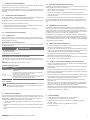 3
3
-
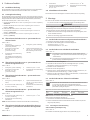 4
4
-
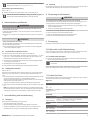 5
5
-
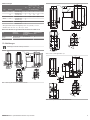 6
6
-
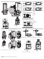 7
7
-
 8
8
-
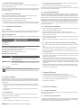 9
9
-
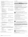 10
10
-
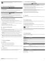 11
11
-
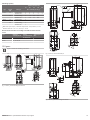 12
12
-
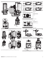 13
13
-
 14
14
-
 15
15
-
 16
16
-
 17
17
-
 18
18
-
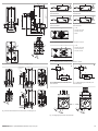 19
19
-
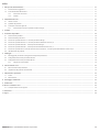 20
20
-
 21
21
-
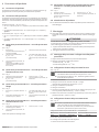 22
22
-
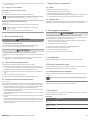 23
23
-
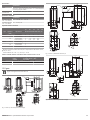 24
24
-
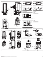 25
25
-
 26
26
-
 27
27
-
 28
28
-
 29
29
-
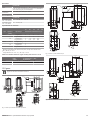 30
30
-
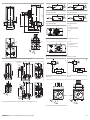 31
31
-
 32
32
-
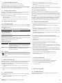 33
33
-
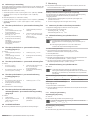 34
34
-
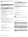 35
35
-
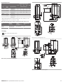 36
36
-
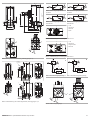 37
37
-
 38
38


en otros idiomas
- français: AVENTICS PM1 Manuel utilisateur
- italiano: AVENTICS PM1 Manuale utente
- svenska: AVENTICS PM1 Användarmanual
Artículos relacionados
-
AVENTICS Pressostat électromécanique, série PM1 El manual del propietario
-
AVENTICS PE2 El manual del propietario
-
-
-
-
AVENTICS Flow rate sensor, series AF2 El manual del propietario