Progress Lighting P250081 Guía de instalación
- Categoría
- Ventiladores domésticos
- Tipo
- Guía de instalación
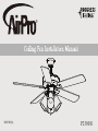
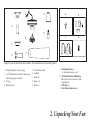
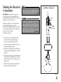
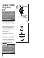
Progress Lighting P250081 es un ventilador de techo con motor que ofrece un flujo de aire potente y silencioso para mantenerte fresco y cómodo en tu hogar. El ventilador cuenta con cinco aspas reversibles de madera, lo que te permite elegir entre dos acabados distintos para que combinen con tu decoración. También incluye un kit de luz con cuatro bombillas para proporcionar iluminación adicional. El ventilador es fácil de instalar y viene con todo el hardware necesario para su montaje. Además, está respaldado por una garantía de 30 años del fabricante.
Progress Lighting P250081 es un ventilador de techo con motor que ofrece un flujo de aire potente y silencioso para mantenerte fresco y cómodo en tu hogar. El ventilador cuenta con cinco aspas reversibles de madera, lo que te permite elegir entre dos acabados distintos para que combinen con tu decoración. También incluye un kit de luz con cuatro bombillas para proporcionar iluminación adicional. El ventilador es fácil de instalar y viene con todo el hardware necesario para su montaje. Además, está respaldado por una garantía de 30 años del fabricante.


-
 1
1
-
 2
2
-
 3
3
-
 4
4
-
 5
5
-
 6
6
-
 7
7
-
 8
8
-
 9
9
-
 10
10
-
 11
11
-
 12
12
-
 13
13
-
 14
14
-
 15
15
-
 16
16
-
 17
17
-
 18
18
-
 19
19
-
 20
20
-
 21
21
-
 22
22
-
 23
23
-
 24
24
-
 25
25
-
 26
26
-
 27
27
-
 28
28


Progress Lighting P250081 Guía de instalación
- Categoría
- Ventiladores domésticos
- Tipo
- Guía de instalación
Progress Lighting P250081 es un ventilador de techo con motor que ofrece un flujo de aire potente y silencioso para mantenerte fresco y cómodo en tu hogar. El ventilador cuenta con cinco aspas reversibles de madera, lo que te permite elegir entre dos acabados distintos para que combinen con tu decoración. También incluye un kit de luz con cuatro bombillas para proporcionar iluminación adicional. El ventilador es fácil de instalar y viene con todo el hardware necesario para su montaje. Además, está respaldado por una garantía de 30 años del fabricante.
en otros idiomas
Artículos relacionados
-
Progress Lighting P250085 AirPro 52-Inch Ceiling Fan Guía de instalación
-
-
-
-
-
-
-
Progress Lighting P2586-7130K Guía de instalación
-
-