Kenwood X302-4 Manual de usuario

Categoría
Amplificadores de audio para automóviles
Tipo
Manual de usuario

El Kenwood X302-4 es un amplificador de potencia de 4 canales de clase D con una potencia máxima de salida de 600 vatios. Es ideal para sistemas de audio de coche de gama alta, y puede utilizarse para alimentar altavoces o subwoofers. El X302-4 cuenta con una variedad de características que lo hacen fácil de usar y versátil, incluyendo un filtro de paso bajo ajustable, un refuerzo de graves y un control de ganancia. También cuenta con protección contra cortocircuitos, sobrecalentamiento y sobrecarga, lo que lo hace una opción segura y fiable para cualquier sistema de audio de coche.

El Kenwood X302-4 es un amplificador de potencia de 4 canales de clase D con una potencia máxima de salida de 600 vatios. Es ideal para sistemas de audio de coche de gama alta, y puede utilizarse para alimentar altavoces o subwoofers. El X302-4 cuenta con una variedad de características que lo hacen fácil de usar y versátil, incluyendo un filtro de paso bajo ajustable, un refuerzo de graves y un control de ganancia. También cuenta con protección contra cortocircuitos, sobrecalentamiento y sobrecarga, lo que lo hace una opción segura y fiable para cualquier sistema de audio de coche.

X302-4
XM302-4
KAC-314
CLASS D FOUR CHANNEL POWER AMPLIFIER
INSTRUCTION MANUAL
AMPLIFICATEUR DE PUISSANCE 4 CANAUX CLASSE D
MODE D’EMPLOI
AMPLIFICADOR DE POTENCIA DE 4 CANALES CLASE D
MANUAL DE INSTRUCCIONES
Take the time to read through this instruction manual.
Familiarity with installation and operation procedures will help you obtain the best performance from
your new power amplier.
For your records
Record the serial number, found on the back of the unit, in the spaces designated on the warranty card, and in the
space provided below. Refer to the model and serial numbers whenever you call upon your Kenwood dealer for
information or service on the product.
Model X302-4 /XM302-4/KAC-314 Serial number
US Residence Only
Register Online
Register your Kenwood product at www.kenwood.com/usa
B5A-3477-10 / 01 (KN / WN)
© 2021 JVCKENWOOD Corporation
213 mm (8-3/8̯)
149 mm (5-7/8̯)
53 mm
(2-1/16̯)
Accessories / Accessoires / Accesorios
Ø4×16 mm
Self-tapping screws
Vis taraudeuses
Tornillo autorroscantes 4Speaker level input cable
Câble d’entrée de niveau d’enceinte
Cable de entrada del nivel de altavoces 1
Dimensions / Dimensions / Dimensiones
Safety precautions
WARNING
To prevent injury or re, take the following precau-
tions:
Mounting and wiring this product requires skills and
experience. For safetys sake, leave the mounting and
wiring work to professionals.
When extending the ignition, battery, or ground wires,
make sure to use automotive-grade wires or other
wires with the range of 5 mm2 (AWG 10) or more to
prevent wire deterioration and damage to the wire
coating.
To prevent a short circuit, never put or leave any metal-
lic objects (such as coins or metal tools) inside the unit.
If the unit starts to emit smoke or strange smells,
turn off the power immediately and consult your
KENWOOD dealer.
Do not touch the unit during use because the sur-
face of the unit becomes hot and may cause burns if
touched.
CAUTION
To prevent damage to the machine, take the follow-
ing precautions:
Be sure the unit is connected to a 12 V DC power sup-
ply with a negative ground connection.
Do not open the top or bottom covers of the unit.
Do not install the unit in a spot exposed to direct
sunlight or excessive heat or humidity. Also avoid
places with too much dust or the possibility of water
splashing.
When replacing a fuse, only use a new one with the
prescribed rating. Using a fuse with the wrong rating
may cause your unit to malfunction.
To prevent a short circuit when replacing a fuse, rst
disconnect the wiring harness.
NOTE
If you experience problems during installation, consult
your KENWOOD dealer.
If the unit does not seem to be working right, consult
your KENWOOD dealer.
Cleaning the unit
If the front panel gets dirty, turn o the power and wipe
the panel with a dry silicon cloth or soft cloth.
CAUTION
Do not wipe the panel with a hard cloth or a cloth damp-
ened by volatile solvents such as paint thinner and alco-
hol. They can scratch the surface of the panel and / or
cause the indicator letters to peel o.
To prevent battery rise
When the unit is used in the ACC ON position without
turning the engine ON, it depletes the battery. Use it after
starting the engine.
Protection function
The protection function is activated in the following
situations:
This unit is equipped with a protection function for
protecting this unit and your speakers from various acci-
dents or problems that can occur.
When the protection function is triggered, the power
indicator goes o and the amplier stops operating.
When a speaker wire may be short-circuited.
When a speaker output contacts ground.
When the unit malfunctions and a DC signal is sent to
the speaker output.
When the internal temperature is high and unit won’t
operate.
Wiring
Take the battery wire for this unit directly from the bat-
tery. If its connected to the vehicles wiring harness, it
can cause blown fuses etc.
If a buzzing noise is heard from the speakers when the
engine is running, connect a line noise lter (optional)
to each of the battery wire.
Do not allow the wire to directly contact the edge of
the iron plate by using Grommets.
Connect the ground wire to a metal part of the car
chassis that acts as an electrical ground passing elec-
tricity to the batterys negative terminal. Do not turn
the power on if the ground wire is not connected.
Be sure to install a protective fuse in the power cord
near the battery. The protective fuse should be the
same capacity as the units fuse capacity or somewhat
larger.
For the power cord and ground, use a vehicle type
(reproof) power wring cord. (Use a power wiring cord
with the range of 5 mm2 (AWG 10) or more.)
When more than one power amplier are going to be
used, use a power supply wiring wire and protective
fuse of greater current-handling capacity than the total
maximum current drawn by each amplier.
Speaker selection
Using speakers with smaller input ratings than the
ampliers output power would result in smoke gener-
ation or equipment failure.
The impedance of the speakers that are going to be
connected should be 2 Ω or greater (for stereo con-
nections), or 4 Ω or greater (for bridged connections).
When more than one set of speakers are going to be
used, calculate the combined impedance of the speak-
ers and then connect suitable speakers to the amplier.
<Example>
Combined
impedance
Installation / Installation / Instalación
Installation procedure
Since there are large variety of settings and
connections possible according to applications,
read the instruction manual well to select the
proper setting and connection.
1. Remove the ignition key and disconnect
the negative terminal of the battery to
prevent short circuits.
2. Set the unit according to the intended
usage.
3. Remove the Dressing cover.
4. Connect the input and output wires of the
units.
5. Connect the speaker wires.
6. Connect the power wire, power control
wire and grounding wire following this
order.
7. Install the installation ttings in the unit.
8. Attach the unit.
9. Attach the Dressing cover.
10. Connect the negative terminal of the
battery.
CAUTION
• Do not install in the below locations;
(Unstable location, In a location that inter-
feres with driving, In a location that gets wet,
In a dusty location, In a place that gets hot, In
a place that gets direct sunlight, In a location
that gets hit by hot air)
Do not install the unit under the carpet.
Otherwise heat build-up occurs and the unit
may be damaged.
Install this unit in a location which allows
heat to easily dissipate. Once installed, do not
place any object on top of the unit.
The surface temperature of the amplier will
become hot during use. Install the amplier
in a place where people, resins, and other
substances that are sensitive to heat will not
come into contact with it.
When making a hole under a seat, inside
the trunk, or somewhere else in the vehicle,
check that there is nothing hazardous on the
opposite side such as a gasoline tank, brake
pipe, or wiring harness, and be careful not to
cause scratches or other damage.
Do not install near the dashboard, rear tray, or
air bag safety parts.
The installation to the vehicle should securely
fasten the unit to a place in which it will not
obstruct driving. If the unit comes off due
to a shock and hits a person or safety part, it
may cause injury or an accident.
After installing the unit, check to make sure
that electrical equipment such as the brake
lamps, turn signal lamps and windshield wip-
ers operate normally.
DUST
POUSSIÈRE
POLVO
MOISTURE
HUMIDITÉ
HUMEDAD
Installation board, etc.
(thickness: 15 mm or more)
Tableau d’installation, etc.
(épaisseur: 15 mm ou plus)
Tablero de instalación, etc.
(grosor: 15 mm o más)
Parts included
Pièces comprises
Partes incluidas
Dressing cover
Enjoliveur
Cubierta de adorno
Protective
cover
Couvercle de
protection
Cubierta
protectora
XM302-4
r
a
NOTE
After wiring, x the protective cover securely with screws and washers.
REMARQUE
Après le câblage, xez fermement le couvercle de protection avec des vis et
des rondelles.
NOTA
Después de realizar el cableado, je rmemente la cubierta protectora con
tornillos y arandelas.
Cap
Capuchon
Tapa
combinée
com
bi
na
d
a
Connections / Raccordements / Conexiones
WARNING Remove the ignition key and disconnect the negative terminal of the battery to prevent short circuits.
AVERTISSEMENT Retirer la clé de contact et débrancher la borne négative de la batterie pour éviter les court-circuits.
ADVERTENCIA
Retire la llave de encendido y desconecte el terminal negativo de la batería para evitar cortocircuitos.
In a computer-equipped vehicle, when you remove the terminal of the battery, the memory may disappear, or a defect may occur in the electrical system of the
vehicle. Consult your dealer for further details.
Dans un véhicule équipé d’un ordinateur, lorsque vous retirez la borne de la batterie, la mémoire peut disparaître ou un défaut peut se produire dans le système élec-
trique du véhicule. Consultez votre revendeur pour de plus amples détails.
En un vehículo equipado con ordenador, cuando extrae el terminal de la batería, la memoria puede desaparecer o puede producirse un defecto en el sistema eléc-
trico del vehículo. Consulte a su proveedor para obtener más detalles.
AFTER MARKET
HEAD UNIT
Battery
Batterie
Batería
Ground wire
Câble de masse
Cable de masa
Battery wire
Câble de la batterie
Cable de la batería
Protective fuse
Fusible de protection
Fusible de protección
Lead terminal
Cosse pour câble
Terminal de cable
WARNING
Particular attention must be given to making
good electrical contact at the amplier-out-
put and speaker terminals.
Poor or loose connections can cause spark-
ing or burning at the terminals because of
the very high power that the amplier can
deliver.
CAUTION
If sound is not output normally, imme-
diately turn power off and check
connections.
Be sure to turn the power o before chang-
ing the setting of any switch.
If the fuse blows, check wires for shorts,
then replace the fuse with one of the same
rating.
Check that no unconnected wires or con-
nectors are touching the car body. Do not
remove caps from unconnected wires or
connectors to prevent short circuits.
Connect the speaker wires to appropriate
speaker connectors separately. Sharing the
negative wire of the speaker or grounding
speaker wires to the metal body of the car
can cause this unit to fail.
After installation, check that the brake
lamps, turn signal lamps and windshield
wipers work properly.
AVERTISSEMENT
Veillez à ce que le contact électrique à la
sortie de l’amplificateur et aux prises des
enceintes soit bien établi.
Un mauvais branchement ou un branche-
ment lâche peut causer des étincelles ou un
réchauement des prises du fait de la très
grande puissance de l’amplicateur.
ATTENTION
En cas d’anomalie, mettre immédiatement
l’appareil hors tension et vérier tous les
raccordements.
• Veiller à mettre l’appareil hors ten-
sion avant de changer la position des
commutateurs.
Si le fusible saute, vérier si les câbles ne
sont pas court-circuités, et remplacer
le fusible par un autre fusible de même
capacité nominale.
Vérier qu’aucun câble ou connecteur non
raccordé ne touche la carrosserie de la
voiture. Ne pas retirer les capuchons des
câbles ou connecteurs non raccordés an
d’éviter tout courtcircuit.
Raccorder séparément les câbles de haut-
parleur aux connecteurs de haut-parleur
appropriés. La mise en commun du câble
négatif d’un haut-parleur ou des fils de
masse des haut-parleurs à la carrosserie
métallique de la voiture pourrait rendre
l’appareil inopérant.
Après l’installation, vérier que les voyants
de frein, les clignotants et les essuie-glace
fonctionnent correctement.
ADVERTENCIA
Debe ponerse especial atención para que se
haga un buen contacto eléctrico en la salida
del amplicador y en los terminales de los
altavoces.
Las conexiones mal hechas o las conexiones
ojas pueden causar chispas o quemaduras
en los terminales debido a la potencia muy
alta que puede suministrar el amplicador.
PRECAUCIÓN
Si el sonido no sale normalmente, desco-
necte inmediatamente la alimentación y
compruebe las conexiones.
No se olvide de desconectar la alimenta-
ción antes de cambiar el ajuste de cual-
quier conmutador.
Si el fusible se quema, compruebe que no
haya un cortocircuito en los cables, luego
cambie el fusible por uno que tenga el
mismo amperaje.
Verifique que ninguno de los cables o
conectores que están sin conectar se
encuentren tocando la carrocería del auto-
móvil. No retire las tapas de los cables o
conectores que están sin conectar para evi-
tar de que se produzcan cortocircuitos.
• Conecte los cables del altavoz a los
conectores adecuados del altavoz separa-
damente. La puesta en contacto de termi-
nales de altavoces distintos, o la conexión
como toma de tierra de los terminales del
altavoz al coche del automóvil, pueden
causar daños a la unidad.
Después de la instalación, compruebe que
las lámparas del freno, luces de destello y
limpiaparabrisas funcionar correctamente.
Power control wire; for “RCA INPUT connection
Câble de commande de l’alimentation; pour «Raccordement RCA INPUT»
Cable de control de alimentación; para “Conexión RCA INPUT”
Power wire and speaker wire connection
Raccordement d’un câble de l’alimentation et d’enceinte
Conexión del cable de alimentación y del altavoz
WARNING
To prevent re caused by a short in the wiring, connect a fusible link
or breaker nearby the batterys positive terminal.
AVERTISSEMENT
Pour éviter tout incendie dû à un court-circuit, insérer un fusible ou un
coupecircuit à proximité de la borne de la batterie.
ADVERTENCIA
Para evitar incendios producidos por cortocircuitos en el cableado,
conecte un fusible o cortacircuito entre la batería y los terminales
de la batería.
Stereo
Stéréo
Estereofónicas
Right
A.ch Droit
Derecho
Left
A.ch Gauche
Izquierdo
Right
B.ch Droit
Derecho
Left
B.ch Gauche
Izquierdo
Bridged / Pont / Puenteada
A.ch
B.ch
NOTE
Do not connect cables and
leads to both RCA cable input
jacks and the speaker level
input terminals simultaneously,
for this may cause malfunction
or damage.
REMARQUE
Ne pas raccorder des câbles
ou conducteurs à la fois aux
prises de sortie pour câble RCA
et aux prises d’entrée de haut-
parleur car l’appareil risquerait
d’être endommagé ou de mal
fonctionner
NOTA
No conecte simultáneamente
cables ni conductores a las
tomas de entrada de cables
RCA o a los terminales de
entrada de altavoces porque
podría producirse una avería.
Connections / Raccordements / Conexiones
RCA INPUT connection
Raccordement RCA INPUT
Conexión RCA INPUT
Speaker level input connections
Raccordement au niveau haut-parleur
Conexión para entrada de altavoz
AFTER MARKET
HEAD UNIT
REAR
L
R
FRONT
L
R
R
L
L
R
R
L
A.ch B.ch
FACTORY INSTALLED
HEAD UNIT
RCA cable
Câble RCA
Cable RCA
Power control wire
Câble de commande de l’alimentation
Cable de control de alimentación
Parts included
Pièces comprises
Partes incluidas
Cable color of the connector / Couleur de câble du connecteur /
Color del cable del conector
A channel Left
A canal Gauche
A canal Izquierdo
White / Blanc / Blanco
White-Black / Blanc-Noir / Blanco-Negro
A channel Right
A canal Droit
A canal Derecho
Gray / Gris / Gris
Gray-Black / Gris-Noir / Gris-Negro
B channel Left
B canal Gauche
B canal Izquierdo
Green / Vert / Verde
Green-Black / Vert-Noir / Verde-Negro
B channel Right
B canal Droit
B canal Derecho
Purple / Violet / Púrpura
Purple-Black / Violet-Noir / Púrpura-Negro
For U.S.A.
FCC CAUTION
Changes or modications not expressly approved by the party responsible for compliance could void the users author-
ity to operate the equipment.
NOTE: This equipment has been tested and found to com-
ply with the limits for a Class B digital device, pursuant
to part 15 of the FCC Rules. These limits are designed to
provide reasonable protection against harmful interference
in a residential installation. This equipment generates, uses
and can radiate radio frequency energy and, if not installed
and used in accordance with the instructions, may cause
harmful interference to radio communications. However,
there is no guarantee that interference will not occur in a
particular installation. If this equipment does cause harmful
interference to radio or television reception, which can be
determined by turning the equipment o and on, the user
is encouraged to try to correct the interference by one or
more of the following measures:
—Reorient or relocate the receiving antenna.
Increase the separation between the equipment and
receiver.
—Connect the equipment into an outlet on a circuit dierent
from that to which the receiver is connected.
—Consult the dealer or an experienced radio/TV technician
for help.
Supplier’s Declaration of Conformity
Trade Name: KENWOOD
Products: CLASS D FOUR CHANNEL
POWER AMPLIFIER
Model Name: X302-4/ XM302-4/KAC-314
Responsible Party: JVCKENWOOD USA CORPORATION
2201 East Dominguez Street,
Long Beach, CA 90810, U.S.A.
PHONE: 310 639-9000
THIS DEVICE COMPLIES WITH PART 15 OF THE FCC
RULES. OPERATION IS SUBJECT TO THE FOLLOWING
TWO CONDITIONS:
(1)THIS DEVICE MAY NOT CAUSE HARMFUL
INTERFERENCE, AND
(2) THIS DEVICE MUST ACCEPT ANY INTERFERENCE
RECEIVED, INCLUDING INTERFERENCE THAT MAY
CAUSE UNDESIRED OPERATION.
System examples / Exemple de configuration / Ejemplos del sistema
4-channel system
Système 4 voies
Sistema de 4 canales
2-channel + Subwoofer system
Système 2 voies + enceinte d’extrêmes graves
Sistema de 2 canales + Altavoz de subgraves
Front left speaker
Haut-parleur avant gauche
Altavoz delantero izquierdo
Front right speaker
Haut-parleur avant droit
Altavoz delantero derecho
Rear left speaker
Haut-parleur arrière gauche
Altavoz trasero izquierdo
Rear right speaker
Haut-parleur arrière droit
Altavoz trasero derecho
L
R
L
R
L
R
L
R
A
B
HEAD UNIT
L
R
L
RB
HEAD UNIT
L
R
L
RA
Left speaker (high pass)
Haut-parleur gauche (ltre passe-haut)
Altavoz izquierdo (paso alto)
Right speaker (high pass)
Haut-parleur droit (ltre passe-haut)
Altavoz derecho (paso alto)
Subwoofer (Bridged)
Haut-parleur d’extrême grave (Pont)
Altavoz de subgraves (Puentead)
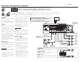
Controls / Contrôles / Controles
This is a 4 channel amplifier in-
cluding 2 stereo amplifiers in a
body. One amplier is referred to
as amplier A and the other is am-
plifier B. This unit is compatible
with a large variety of systems by
combining the switches and func-
tions described in the following.
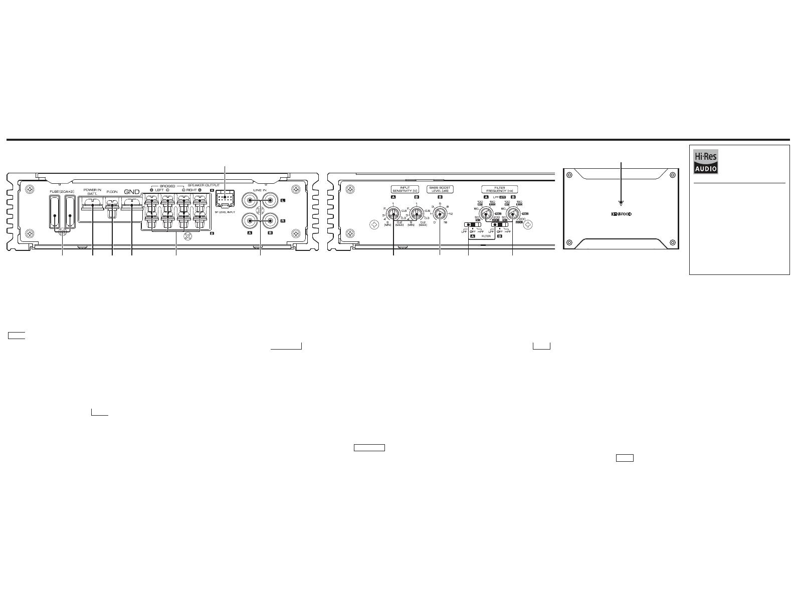
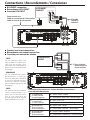
Fuse (20 A× 2)
NOTE
If you can’t nd the specied capacity
fuse at your store etc., consult your
KENWOOD dealer.
Battery terminal (POWER IN
BATT.)
Power control terminal (P.CON)
Controls the unit ON/ OFF.
Ground terminal (GND)
SPEAKER OUTPUT terminals
(A.ch/ B.ch)
• Stereo connections:
When you wish to use the unit as a
stereo amplifier, stereo connections
are used. The speakers to be con-
nected should have an impedance of
2 Ω or greater. When multiple speak-
ers are to be connected, ensure that
the combined impedance is 2 Ω or
greater for each channel.
• Bridged connections:
When you wish to use the unit as a
high-output amplifier, bridged con-
nections are used. (Make connections
to the LEFT channel and the RIGHT
channel SPEAKER OUTPUT termi-
nals.) The speakers to be connected
should have an impedance of 4 Ω or
greater. When multiple speakers are to
be connected, ensure that the com-
bined impedance is 4 Ω or greater.
SP LEVEL INPUT terminal
The output from the FACTORY
INSTALLED HEAD UNIT up to 50 W
can be input. The power is turned
on and o as the unit detects input
signal (SIGNAL SENSING TURN-ON).
Therefore it is not necessary to con-
nect the power control wire.
LINE IN terminal (A.ch/ B.ch)
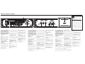
INPUT SENSITIVITY control
(A.ch/ B.ch)
Set this control according to the
pre-output level of the HEAD UNIT
connected with this unit.
NOTE
For the pre-output level, refer to the
“Specifications” in the instruction
manual of the HEAD UNIT.
BASS BOOST LEVEL control
(B.ch)
Sets the low frequency level to be
compensated.
FILTER switch (A.ch/ B.ch)
This switch allows to apply high-pass
or low-pass filtering to the speaker
outputs.
HPF (High-Pass Filter) position:
The lter outputs the band of higher
frequencies than the frequency set
with the “FILTER FREQUENCY” control.
• OFF position:
The entire bandwidth is output with-
out ltering.
LPF (Low-Pass Filter) position:
The lter outputs the band of lower
frequencies than the frequency set
with the “FILTER FREQUENCY” control.
FILTER FREQUENCY control
(A.ch/ B.ch)
Sets the cutoff frequency when the
“FILTER” switch is set to “HPF” or “LPF”.
Power indicator
When the power is turned on, the
Power indicator lights.
Ceci est un amplificateur à 4
canaux avec deux amplificateurs
stéréophoniques en un élément;
l’un appelé Amplificateur A,
l’autre Amplicateur B. Cet appa-
reil est compatible avec diverses
congurations de chaîne, simple-
ment en sélectionnant les posi-
tions des commutateurs et les
fonctions comme indiqué ci-après.
Fusible (20 A× 2)
REMARQUE
Si vous ne trouvez pas de fusible de
calibre adéquat dans le commerce,
etc., contacter votre agent KENWOOD.
Borne POWER IN BATT.
(alimentation)
Borne P.CON (l de commande
d’alimentation)
Commande l’unité ON/ OFF.
Borne GND (masse)
Bornes SPEAKER OUTPUT
(A.ch/ B.ch)
• Connexions stéréo:
Pour utiliser l’appareil comme ampli-
ficateur stéréo, des connections
stéréo doivent être utilisées. Les haut-
parleurs à connecter doivent avoir
une impédance de 2 ohms ou supé-
rieure. Lorsque plusieurs haut-parleurs
doivent être connectés, s’assurer que
l’impédance combinée soit de 2 ohms
ou supérieure pour chaque canal.
Connexions en pont:
Pour l’utilisation de l’appareil
comme amplificateur à haute puis-
sance de sortie, des connections en
pont doivent être utilisées. (Faire les
connexions aux bornes SPEAKER
OUTPUT du canal gauche (LEFT) et
du canal droit (RIGHT) .) Les haut-
parleurs à connecter doivent avoir
une impédance de 4 ohms ou supé-
rieure. Lorsque plusieurs haut-parleurs
doivent être connectés, s’assurer que
l’impédance combinée soit de 4 ohms
ou supérieure.
Borne SP LEVEL INPUT (niveau
haut-parleur)
La puissance de sortie maximum de
la FACTORY INSTALLED HEAD UNIT ne
doit pas dépasser 50 W. L’alimentation
est activée et désactivée lorsque
l’appareil détecte le signal d’entrée
(SIGNAL SENSING TURN-ON). C’est
pourquoi il nest pas nécessaire de
connecter le câble de commande de
l’alimentation.
Borne LINE IN (entrée de ligne)
(A.ch/ B.ch)
Commande INPUT SENSITIVITY
(sensibilité d’entrée) (A.ch/ B.ch)
Régler cette commande selon le
niveau de pré-sortie de la HEAD UNIT
branché à cet amplicateur.
REMARQUE
Se référer à la section «Spécications»
du manuel des instructions de la
HEAD UNIT à propos du niveau de
pré-sortie.
Commande BASS BOOST LEVEL
(B.ch)
Règle le niveau de basse fréquence
devant être compensé.
Commutateur FILTER
(A.ch/ B.ch)
Ce commutateur permet d’effectuer
un ltrage des graves, ou des aigus,
appliqués vers les haut-parleurs.
Position HPF (Filtre passe-haut):
Le filtre laisse passer les fréquences
supérieures à la fréquence précisée
au moyen de la commande «FILTER
FREQUENCY».
• Position OFF:
Le ltre n’agit pas, autrement dit tout
le spectre des fréquences est présent
en sortie.
Position LPF (Filtre passe-bas):
Le filtre laisse passer les fréquences
inférieures à la fréquence précisée
au moyen de la commande «FILTER
FREQUENCY».
Commande FILTER FREQUENCY
(A.ch/ B.ch)
Cette commande permet de préci-
ser la fréquence de coupure quand
le commutateur «FILTER» est sur la
position «HPF» ou «LPF».
Indicateur d’alimentation
Lorsque l’alimentation est activée, l’in-
dicateur d’alimentation s’illumine.
Este es un amplicador de 4 cana-
les con dos amplificadores esté-
reo en un mismo cuerpo. Uno de
los amplicadores recibe el nom-
bre amplicador A y el otro el de
amplificador B. Combinando los
conmutadores y las funciones des-
critas a continuación, esta unidad
amplificadora es compatible con
una amplia gama de sistemas.
Fusible (20 A× 2)
NOTA
Si no puede encontrar el fusible
de la capacidad especificada en su
almacén etc., consulte su distribuidor
KENWOOD.
Terminal POWER IN BATT.
(alimentación)
Terminal P.CON (control de
corriente)
Controla la conexión/ desconexión de
la unidad.
Terminal GND (tierra)
Terminales SPEAKER OUTPUT
(A.ch/ B.ch)
• Conexiones estereofónicas:
Cuando desee usar la unidad como
un amplicador estereofónico, usted
deberá utilizar conexiones estereo-
fónicas. Los altavoces a conectar
deberán tener una impedancia de
2 ohmios o mayor. Cuando vaya a
conectar múltiples altavoces, asegú-
rese de que la impedancia combinada
sea de 2 ohmios o mayor para cada
canal.
Conexiones en puente:
Cuando desee usar la unidad como un
amplificador de alta potencia, usted
deberá utilizar conexiones en puente.
(Haga las conexiones a los termina-
les de salida de altavoces (SPEAKER
OUTPUT) de los canales izquierdo
(LEFT) y derecho (RIGHT) .) Los
altavoces a conectar deberán tener
una impedancia de 4 ohmios o mayor.
Cuando vaya a conectar múltiples
altavoces, asegúrese de que la impe-
dancia combinada sea de 4 ohmios
o mayor.
Terminal SP LEVEL INPUT
(entrada de altavoz)
El FACTORY INSTALLED HEAD UNIT
deberá tener una potencia de salida
máxima no superior a 50 W. La ali-
mentación se enciende y apaga con-
forme la unidad detecte una señal de
entrada (SIGNAL SENSING TURN-ON).
Por lo tanto no es necesario conectar
el cable de control de alimentación.
Terminal LINE IN (entrada de
linea) (A.ch/ B.ch)
Control INPUT SENSITIVITY
(sensibilidad de entrada) (A.ch/B.
ch)
Ajustar este control de acuerdo con
el nível de presalida de la HEAD UNIT
conectada a este amplicador.
NOTA
Referir a “Especicaciones” del manual
de instrucciones de la HEAD UNIT con
respecto al nível de presalida.
Control BASS BOOST LEVEL
(B.ch)
Ajusta el nivel de baja frecuencia que
se va a compensar.
Conmutador FILTER (A.ch / B.ch)
Este conmutador permite aplicar la
ltración de paso alto o paso bajo a
las salidas de los altavoces.
Posición HPF (ltro de paso alto):
El filtro da salida a la banda de fre-
cuencias más altas que la frecuen-
cia ajustada con el control “FILTER
FREQUENCY”.
• Posición OFF:
Todo el ancho de banda sale sin
ltración.
Posición LPF (ltro de paso bajo):
El filtro da salida a la banda de fre-
cuencias más bajas que la frecuen-
cia ajustada con el control “FILTER
FREQUENCY”.
Control FILTER FREQUENCY
(A.ch/ B.ch)
Ajusta la frecuencia de corte cuando
el conmutador “FILTER” está en “HPF”
o “LPF”.
Indicador de potencia
Cuando la alimentación se activa, el
indicador de potencia se ilumina.
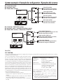
The product with this logo is
conformed to Hi-Resolution
Audio standard defined by
Japan Audio Society. This logo
is used under license from
Japan Audio Society.
It is recommended that a car audio sys-
tem should be configured with all High-
Resolution Audio compatible products from
player to speaker to enjoy its high quality
sound.
Il est recommandé qu’un système audio de
voiture doit être conguré avec tous les pro-
duits compatibles Audio Haute Résolution
de lecteur à haut-parleur pour apprécier son
son haute qualité.
Se recomienda que el sistema de audio del
coche esté congurado con todos los pro-
ductos compatibles con el audio de alta
resolución, desde el reproductor hasta los
altavoces, para disfrutar su alta calidad de
sonido.
Troubleshooting Guide
What might appear to be a malfunction in your unit may just be the result of slight misoperation or miswiring.
Before calling service, rst check the following table for possible problems.
PROBLEM POSSIBLE CAUSE SOLUTION
No sound.
(No sound from one
side.)
(Blown fuse.)
Input (or output) cables are disconnected.
Protection circuit may be activated.
Volume is too high.
The speaker cord is shorted.
Connect the input (or output) cables.
Check connections by referring to “Protection
function.
Replace the fuse and use lower volume.
After check the speaker cord and xing the
cause of the short, replace the fuse.
The output level is too
small (or too large). The input sensitivity adjusting control is not
set to the correct position. Adjust the control correctly referring to “Con-
trols.
The sound quality is
bad.
(The sound is
distorted.)
The speakers wire are connected with
wrong / polarity.
A speaker wire is pinched by a screw in the
car body.
The switches may be set improperly.
Connect them properly checking the /
of the terminals and wires well.
Connect the speaker wire again so that it is
not pinched by anything.
Set switches properly by referring to “Con-
trols.
Guide de dépannage
Ce qui peut apparaître comme un mauvais fonctionnement de votre appareil nest peut-être que le résultat
d’une mauvaise opération ou d’une mauvaise connexion. Avant d’appeler un centre de service, vériez d’abord
dans le tableau suivant les problèmes possibles.
PROBLEME CAUSE POSSIBLE SOLUTION
Absence de sons.
(Pas de son d’un côté)
(Fusible grillé)
Les câbles d’entrée (ou de sortie) sont
débranchés.
Le circuit de protection peut être
actionné.
Le volume est trop fort.
Les ls de raccordement d’enceinte sont
en court-circuit.
Brancher les câbles d’entrée (ou de sortie).
Vérier les raccordements en se reportant au
paragraphe «Fonction de protection».
Remplacez le fusible et utilisez un niveau de
volume plus faible.
Après avoir vérié le câble d’enceinte et réparé
la cause du court-circuit, remplacez le fusible.
Niveau de sortie trop
faible (ou trop fort).
La commande de réglage de la sensibilité d’en-
trée nest pas amenée sur la bonne position.
Faire le réglage correctement en se reportant
aux indications données en «Contrôles».
La qualité sonore est
mauvaise.
(Le son est distordu.)
Les câbles de haut-parleur ont été raccor-
dés en inversant la polarité / .
Un câble de haut-parleur est pincé par
une vis dans le châssis de la voiture.
Les commutateurs ne sont peut-être pas
positionnés comme il convient.
Raccorder correctement en respectant les indi-
cations et des bornes et des câbles.
Rebrancher le câble de haut-parleur en évitant
tout pincement
Positionner les commutateurs en tenant
compte des indications fournies aux para-
graphes «Contrôles».
Guía para la solución de averías
Lo que podría parecer una falla de funcionamiento de su unidad podría ser simplemente el resultado de un
pequeño error de operación o de un defecto de conexión. Antes de acudir al servicio, verique primero el
siguiente cuadro sobre los problemas que se podrían presentar.
PROBLEMA CAUSA POSIBLE SOLUCION
No hay sonido.
(No hay sonido de un
lado.)
(Fusible fundido)
Los cables de entrada (o salida) están des-
conectados.
El circuito de protección puede estar acti-
vado.
El volumen está demasiado alto.
El cable del altavoz está cortocircuitado.
Conecte los cables de entrada (o salida).
Compruebe las conexiones consultando “Fun-
ción de protección.
Reemplace el fusible y utilice volumen bajo.
Después de revisar el cable del altavoz y arreglar
la causa del cortocircuito, reemplace el fusible.
El nivel de salida está
muy bajo (o muy alto) El control de ajuste de sensibilidad de
entrada no está en la posición correcta. Ajuste bien el control consultando en “Contro-
les”.
La calidad del sonido
es mala.
(El sonido está
distorsionado.)
Los cables de los altavoces están conecta-
dos con las polaridades /invertidas.
Un cable de altavoz está pellizcado por
un tornillo de la carrocería del automóvil.
Los conmutadores pueden estar mal ajus-
tados.
Conéctelos correctamente asegurándose bien
de cuáles son los terminales y .
Vuelva a conectar los cables de los altavoces de
forma que no queden pellizcados.
Ponga bien los conmutadores consultando
“Controles.
Spécifications
Les spécifications sont sujettes à changements sans
notication.
Section audio
Puissance de sortie nominale (+B =14,4 V)
Stéréo (4 Ω)....................50 W ×4 (20 Hz–20 kHz, ≤ 1,0% THD)
Stéréo (2 Ω)...................................... 75 W×4 (1 kHz, ≤ 1,0% THD)
Pont (4 Ω)........................................150 W ×2 (1 kHz, ≤ 1,0% THD)
Impédance denceinte........................4 Ω (2 Ω à 8 Ω admissible)
(Connexions en pont: 4 Ω à 8 Ω admissible)
Réponse en fréquence (+0, −3 dB).........................20 Hz–50 kHz
Sensibilité d’entrée (RCA) ...................................................0,2 V–5,0 V
Taux de signal/ bruit.......................................................................100 dB
Impédance dentrée.......................................................................... 10 kΩ
Fréquence du ltre passe-bas (−12 dB/oct.)
....................................................................50 Hz–200 Hz (variable)
Fréquence du ltre passe-haut (−12 dB/oct.)
....................................................................50 Hz–200 Hz (variable)
Control d’amplication des basses (40 Hz/ canal B)
............................................................................0 +18 dB (variable)
Général
Tension de fonctionnement.........Batterie de voiture 12 V CC
Courant absorbé.................................................................................... 20 A
Taille d’installation (L×H×P)..........................213 ×53 ×149 mm
8-3/8× 2-1/16× 5-7/8 pouce
Masse .......................................................................................1,4 kg (3,1 lbs)
Especificaciones
Las especicaciones se encuentran sujetas a cambios
sin previo aviso.
Sección de audio
Salida de potencia nominal (+B = 14,4 V)
Estereofónicas (4 Ω)......................................................................50 W× 4
(20 Hz–20 kHz, ≤ 1,0% de distorsión armónica total)
Estereofónicas (2 Ω)......................................................................75 W× 4
(1 kHz, ≤ 1,0% de distorsión armónica total)
Puenteada (4 Ω) ...........................................................................150 W× 2
(1 kHz, ≤ 1,0% de distorsión armónica total)
Impedancia de altavoz......................... 4 Ω (2 Ω a 8 Ω permitido)
(Conexiones en puente: 4 Ω a 8 Ω permitido)
Respuesta de frecuencia (+0, −3 dB).....................20 Hz–50 kHz
Sensibilidad de entrada (RCA) .........................................0,2 V–5,0 V
Relación señal a ruido..........................................................................100 dB
Impedancia de entrada ........................................................................10 kΩ
Frecuencia del ltro pasa bajos (−12 dB/octava)
....................................................................50 Hz–200 Hz (variable)
Frecuencia del ltro pasa altos (−12 dB/ octava)
........................................................................50 Hz–200 Hz (variable)
Control acentuador de graves (40 Hz/ canal B)
............................................................................0 +18 dB (variable)
General
Tensión de funcionamiento ..........Batería de coche de 12 V CC
Consumo..................................................................................................... 20 A
Tamaño de instalación (Anch
×
Alt
×
Prof )....
213× 53× 149 mm
8-3/8× 2-1/16× 5-7/8 pulgada
Peso .....................................................................................1,4 kg (3,1 libras)
Specifications
Specications subject to change without notice.
Audio section
Rated power output (+B= 14.4 V)
Stereo (4 Ω).................. 50 W×4 (20 Hz–20 kHz, ≤ 1.0% THD)
Stereo (2 Ω).....................................75 W ×4 (1 kHz, ≤ 1.0% THD)
Bridged (4 Ω)...............................150 W× 2 (1 kHz, ≤ 1.0% THD)
Speaker impedance.............................4 Ω (2 Ω to 8 Ω allowable)
(Bridged connection: 4 Ω to 8 Ω allowable)
Frequency response (+0, −3 dB)..............................20 Hz–50 kHz
Input sensitivity (RCA)............................................................0.2 V–5.0 V
Signal to noise ratio.........................................................................100 dB
Input impedance................................................................................ 10 kΩ
Low pass lter frequency (−12 dB / oct.)
....................................................................50 Hz–200 Hz (variable)
High pass lter frequency (−12 dB /oct.)
....................................................................50 Hz–200 Hz (variable)
Bass boost control (40 Hz/ B channel)
............................................................................0 +18 dB (variable)
General
Operating voltage................................................12 V DC car battery
Current consumption......................................................................... 20 A
Dimensions (W×H×D).....................................213 ×53 ×149 mm
8-3/8× 2-1/16× 5-7/8 inch
Weight.....................................................................................1.4 kg (3.1 lbs)
50 Watts RMS× 4 at 4 Ohms and ≤ 1%
THD+N
85 dBA (Reference: 1 Watt into 4 Ohms)
50 Watts RMS× 4 à 4 Ohms et ≤ 1%
THD+N
85 dBA (Référence: 1 Watt dans 4 Ohms)
50 Vatios RMS× 4 a 4 Ohmios y ≤ 1% de
distorsión armónica total+N
85 dBA (Referencia: 1 Vatio en 4 Ohmios)
Declaration of Conformity with regard to the
EMC Directive 2014/30/EU
Declaration of Conformity with regard to the
RoHS Directive 2011/65/EU
Manufacturer:
JVCKENWOOD Corporation
3-12, Moriya-cho, Kanagawa-ku, Yokohama-shi,
Kanagawa, 221-0022, JAPAN
EU Representative:
JVCKENWOOD Europe B.V.
Amsterdamseweg 37, 1422 AC Uithoorn,
THE NETHERLANDS
Déclaration de conformité se rapportant à la
directive EMC 2014/30/UE
Déclaration de conformité se rapportant à la
directive RoHS 2011/65/UE
Fabricant:
JVCKENWOOD Corporation
3-12, Moriya-cho, Kanagawa-ku, Yokohama-shi,
Kanagawa, 221-0022, JAPAN
Représentants dans l’UE:
JVCKENWOOD Europe B.V.
Amsterdamseweg 37, 1422 AC Uithoorn, PAYS-BAS
Declaración de conformidad con respecto a la
Directiva EMC 2014/30/UE
Declaración de conformidad con respecto a la
Directiva RoHS 2011/65/UE
Fabricante:
JVCKENWOOD Corporation
3-12, Moriya-cho, Kanagawa-ku, Yokohama-shi,
Kanagawa, 221-0022, JAPAN
Representante en la UE:
JVCKENWOOD Europe B.V.
Amsterdamseweg 37, 1422 AC Uithoorn, PAÍSES
BAJOS
Information on Disposal of Old Electrical and
Electronic Equipment (applicable for countries
that have adopted separate waste collection
systems)
Products with the symbol (crossed-out wheeled
bin) cannot be disposed as household waste.
Old electrical and electronic equipment should be recycled
at a facility capable of handling these items and their waste
byproducts. Contact your local authority for details in locating
a recycle facility nearest to you. Proper recycling and waste
disposal will help conserve resources whilst preventing detri-
mental eects on our health and the environment.
Information sur l’élimination des anciens équipements
électriques et électroniques (applicable dans les pays qui
ont adopté des systèmes de collecte sélective)
Les produits sur lesquels le pictogramme (poubelle barrée) est
apposé ne peuvent pas être éliminés comme ordures ménagères.
Les anciens équipements électriques et électroniques doivent
être recyclés sur des sites capables de traiter ces produits et
leurs déchets. Contactez vos autorités locales pour connaître
le site de recyclage le plus proche. Un recyclage adapté et
l’élimination des déchets aideront à conserver les ressources
et à nous préserver des leurs eets nocifs sur notre santé et sur
l’environnement.
Información acerca de la eliminación de equipos eléctri-
cos y electrónicos al nal de la vida útil (aplicable a los
países que hayan adoptado sistemas independientes de
recogida de residuos)
Los productos con el símbolo de un contenedor con ruedas
tachado no podrán ser desechados como residuos domésticos.
Los equipos eléctricos y electrónicos al nal de la vida útil,
deberán ser reciclados en instalaciones que puedan dar el
tratamiento adecuado a estos productos y a sus subproductos
residuales correspondientes. Póngase en contacto con su
administración local para obtener información sobre el punto
de recogida más cercano. Un tratamiento correcto del reciclaje
y la eliminación de residuos ayuda a conservar los recursos
y evita al mismo tiempo efectos perjudiciales en la salud y el
medio ambiente.
For Israel
ʯʹʩʩʰʥʸʨʷʬʠʥʩʬʮʹʧʣʥʩʶʬʹʤʴʹʠʬʤʫʬʹʤʸʡʣʡʲʣʩʮ
ʺʣʸʴʥʮʤʴʹʠʳʥʱʩʠʺʫʸʲʮʡʺʥʹʮʺʹʮʹʺʥʰʩʣʮʬʩʨʰʥʥʬʸ
ʭʲʤʴʹʠʧʴʯʥʮʩʱʤʭʲʭʩʸʶʥʮʪʩʬʹʤʬʯʺʩʰʠʬ
ʣʥʩʶʸʦʧʮʬʹʩʤʬʩʢʸʺʩʺʩʡʤʴʹʠʫʥʩʬʲX
ʬʴʨʬʬʢʥʱʮʤʯʷʺʮʡʯʹʩʩʰʥʸʨʷʬʠʥʩʬʮʹʧ
ʭʲʸʹʷʥʸʶʭʤʬʹʩʠʥʥʬʤʩʸʶʥʺʡʥʤʬʠʫʭʩʨʩʸʴʡ
ʯʷʺʮʺʥʣʥʠʭʩʨʸʴʺʬʡʷʬʺʩʮʥʷʮʤʺʥʹʸʤ
ʤʴʹʠʬʤʫʬʹʤʥʸʥʦʧʩʮʭʫʩʬʠʡʥʸʷʤʸʥʦʧʩʮʤ
ʺʥʲʴʹʤʲʥʰʮʬʥʭʩʡʠʹʮʸʮʹʬʥʸʦʲʩʭʩʺʥʠʰ
ʤʡʩʡʱʤʬʲʥʥʰʺʥʠʩʸʡʬʲʺʥʩʬʩʬʹ
For Turkey
Bu ürün 28300 sayılı Resmi Gazetede yayımlanan Atik
Elektrikli ve Elektronik Eşyalarin Kontrolü Yönetmeliğe uygun
olarak üretilmiştir.
Eski Elektrik ve Elektronik Ekipmanların İmha Edilmesi
Hakkında Bilgi (ayrı atık toplama sistemlerini kullanan
ülkeleri için uygulanabilir)
Sembollü (üzerinde çarpı işareti olan çöp kutu-
su) ürünler ev atıkları olarak atılamaz.
Eski elektrik ve elektronik ekipmanlar, bu ürün-
leri ve ürün atıklarını geri dönüştürebilecek
bir tesiste değerlendirilmelidir. Yaşadığınız
bölgeye en yakın geri dönüşüm tesisinin yerini
öğrenmek için yerel makamlara müracaat edin.
Uygun geri dönüşüm ve atık imha yöntemi sağlığımız ve
çevremiz üzerindeki zararlı etkileri önlerken kaynakların
korunmasına da yardımcı olacaktır.
X302-4 only / X302-4 uniquement /
X302-4 solamente
Declaration of Conformity with
regard to the Electromagnetic
Compatibility Regulations 2016
(S.I. 2016/1091)
Declaration of Conformity with
regard to the Restriction of
the Use of Certain Hazardous
Substances in Electrical and
Electronic Equipment Regulations
2012 (S.I. 2012/3032)
Manufacturer:
JVCKENWOOD Corporation
3-12, Moriya-cho, Kanagawa-ku, Yokohama-shi,
Kanagawa, 221-0022, JAPAN
UK Importer:
JVCKENWOOD U.K. Limited
First Floor, Gleneagles, the Belfry, Colonial Way,
Watford, Hertfordshire WD24 4WH, UNITED
KINGDOM
For Europe / Pour l’Europe / Para Europa
X302-4 only /
X302-4 uniquement /
X302-4 solamente
  • Page 1 1
  • Page 2 2
  • Page 3 3
  • Page 4 4
  • Page 5 5
  • Page 6 6
  • Page 7 7
  • Page 8 8
  • Page 9 9
  • Page 10 10

Kenwood X302-4 Manual de usuario

Categoría
Amplificadores de audio para automóviles
Tipo
Manual de usuario

El Kenwood X302-4 es un amplificador de potencia de 4 canales de clase D con una potencia máxima de salida de 600 vatios. Es ideal para sistemas de audio de coche de gama alta, y puede utilizarse para alimentar altavoces o subwoofers. El X302-4 cuenta con una variedad de características que lo hacen fácil de usar y versátil, incluyendo un filtro de paso bajo ajustable, un refuerzo de graves y un control de ganancia. También cuenta con protección contra cortocircuitos, sobrecalentamiento y sobrecarga, lo que lo hace una opción segura y fiable para cualquier sistema de audio de coche.

En otros idiomas