Broan 402101 Manual de usuario
- Categoría
- Campanas de cocina
- Tipo
- Manual de usuario

READ AND SAVE
THESE INSTRUCTIONS
!
INTENDED FOR DOMESTIC
COOKING ONLY.
!
WARNING
TO REDUCE THE RISK OF FIRE, ELECTRIC SHOCK,
OR INJURY TO PERSONS, OBSERVE THE FOLLOW-
ING:
1. Use this unit only in the manner intended by the manu-
facturer. If you have questions, contact the manufac-
turer at the address or telephone number listed in the
warranty.
2. Before servicing or cleaning unit, switch power off at
service panel and lock the service disconnecting
means to prevent power from being switched on acci-
dentally. When the service disconnecting means can-
not be locked, securely fasten a prominent warning
device, such as a tag, to the service panel.
3. Installation work and electrical wiring must be done
by a qualified person(s) in accordance with all appli-
cable codes and standards, including fire-rated con-
struction codes and standards.
4. Sufficient air is needed for proper combustion and ex-
hausting of gases through the flue (chimney) of fuel
burning equipment to prevent backdrafting. Follow the
heating equipment manufacturer’s guideline and safety
standards such as those published by the National Fire
Protection Association (NFPA), and the American So-
ciety for Heating, Refrigeration and Air Conditioning En-
gineers (ASHRAE), and the local code authorities.
5. When cutting or drilling into wall or ceiling, do not dam-
age electrical wiring and other hidden utilities.
6. To reduce the risk of fire or electric shock, do not use
this range hood with an additional speed control de-
vice.
7. Ducted fans must always be vented to the outdoors.
8. To reduce the risk of fire, use only metal ductwork.
9. Use with approved cord-connection kit only.
10. This unit must be grounded.
TO REDUCE THE RISK OF A RANGE TOP GREASE
FIRE:
1. Never leave surface units unattended at high settings.
Boilovers cause smoking and greasy spillovers that
may ignite. Heat oils slowly on low or medium settings.
2. Always turn hood ON when cooking at high heat or
when cooking flaming foods.
3. Clean ventilating fans frequently. Grease should not
be allowed to accumulate on fan or filter.
4. Use proper pan size. Always use cookware appropri-
ate for the size of the surface element.
TO REDUCE THE RISK OF INJURY TO PERSONS IN
THE EVENT OF A RANGE TOP GREASE FIRE, OB-
SERVE THE FOLLOWING:*
1. SMOTHER FLAMES with a close-fitting lid, cookie
sheet, or metal tray, then turn off the burner. BE CARE-
FUL TO PREVENT BURNS. If the flames do not go
out immediately, EVACUATE AND CALL THE FIRE DE-
PARTMENT.
2. NEVER PICK UP A FLAMING PAN - You may be
burned.
3. DO NOT USE WATER, including wet dishcloths or tow-
els - a violent steam explosion will result.
4. Use an extinguisher ONLY if:
A. You know you have a Class ABC extinguisher and
you already know how to operate it.
B. The fire is small and contained in the area where it
started.
C. The fire department is being called.
D. You can fight the fire with your back to an exit.
* Based on “Kitchen Fire Safety Tips” published by NFPA.
CAUTION
!
1. For general ventilating use only. Do not use to exhaust
hazardous or explosive materials and vapors.
2. To avoid motor bearing damage and noisy and/or
unbalanced impellers, keep drywall spray, construction
dust, etc. off power unit.
3. For best capture of cooking impurities, your range hood
should be mounted 18-24" above the cooking surface.
4. Please read specification label on product for further
information and requirements.
!
PREVISTO PARA COCINAR
DOMÉSTICO SOLAMENTE.
!
ADVERTENCIA
PARA REDUCIR EL RIESGO DE INCENDIO, CHOQUE
ELECTRICO, O LESION A PERSONAS, PROCURE LO
SIGUIENTE:
1. Utilice esta unidad sólo en la manera prescrita por el
fabricante. Si tiene usted alguna pregunta, comuníquese
con el fabricante a la dirección o el teléfono indicados
en la garantía.
2. Antes de limpiar o de poner en servicio la unidad,
apague el interruptor en el panel de servicio, y asegure
el panel de servicio para evitar que se encienda
accidentalmente. Cuando el dispositivo para
desconectar el servicio eléctrico no puede ser cerrado
con algún tipo de traba, sujete fuertemente al panel de
servicio, una etiqueta de advertencia prominente.
3. Todo trabajo de instalación y cableado eléctrico debe
ser realizado por personal calificado y de acuerdo con
todos los códigos y normas pertinentes, incluyendo los
códigos y normas relacionados con construcción
clasificada para incendio.
4. Aire suficiente es necesario para facilitar la combustión
adecuada y la salida apropiada de gases por la
chimenea de la unidad y para evitar corrientes de aire
invertidas. Siga las instrucciones y medidas de
seguridad del fabricante del equipo y de las sociedades
profesionales de equipos de calentadores y los
reglamentos de seguridad locales.
5. A cortar o perforar la pared o el techo, no dañe el
cableado eléctrico u otros servicios públicos ocultos a
la vista.
6. Para reducir el riesgo de incendio o de descarga
eléctrica, no utilice este ventilador con ningún dispositivo
de una control de velocidad de estado sólido adicional.
7. Los abanicos con ducto deberán siempre tener una
salida hacia el exterior.
8. Para reducir el riesgo de incendio, use sólo ductos de
metal.
9. Uso con el kit aprobado del la conexión de la cuerda
solamente.
10. Esta unidad se debe instalar con tierra efectiva.
PARA REDUCIR EL RIESGO DE INCENDIO DEBIDO A
GRASA ACUMULADA EN LAS HORNILLAS:
1. Nunca deje sin atender las unidades de superficie
cuando tengan ajustes altos. Los reboses pueden
provocar humo y derrames grasosos que se pueden
incendiar. Caliente lentamente el aceite en un ajuste
bajo o medio.
2. Siempre ENCIENDA la campana cuando cocine con
alta temperatura o cuando cocine alimentos que se
puedan incendiar.
3. Limpie con frecuencia los ventiladores. No debe permitir
que la grasa se acumule en el ventilador ni en el filtro.
4. Utilice un sartén de tamaño adecuado. Siempre utilice
el utensilio adecuado al tamaño del elemento de
superficie.
PARA REDUCIR EL RIESGO DE LESION A PERSONAS
RESULTADO DE UN INCENDIO DEBIDO A GRASA
ACUMULADA EN LAS HORNILLAS, PROCURE LO
SIGUIENTE:*
1. AHOGUE LAS LLAMAS con una tapa ajustada o
charola de metal, después apague la hornilla. TENGA
CUIDADO A FIN DE EVITAR QUEMADURAS. Si las
llamas no se apagan de inmediato, EVACUE Y AVISE
A LOS BOMBEROS.
2. NO LEVANTE NUNCA UNA SARTEN QUE ESTE EN
LLAMAS - Usted se podrá quemar.
3. NO UTILICE AGUA, incluyendo toallas de cocina
mojadas - puede resultar una explosión de vapor violenta.
4. Utilice un extinguidor SOLAMENTE si:
A. Usted sabe que tiene un extinguidor de clase
ABC y lo sabe utilizar.
B. El incendio es pequeño y contenido dentro del
área donde se inició.
C. Los bomberos han sido avisados.
D. Usted puede combatir el incendio con una salida a
su espalda.
* Basado en las recomendaciones para “Seguridad en
la Cocina” publicadas por la NFPA de los EEUU.
40000 HOOD
EXTRACTOR 40000
41000 & 41000MX SERIES/
MICROTEK
®
SYSTEM I
SISTEMA I DE LA SERIE
MICROTEK
®
41000 Y 41000MX
42000 & 42000D HOODS
EXTRACTOR 42000
ECONOMY RANGE HOOD
INSTALLATION INSTRUCTIONS
INSTALLER: Leave This Manual
With Homeowner.
HOMEOWNER: Use and Care
Information on Page 5.
INSTALADOR: Deje este manual con el
dueño de la casa.
DUEÑO DE LA CASA: Información acerca d
el uso y los cuidados en la página 5.
INSTRUCCIONES DE INSTALACION
DE LOS EXTRACTORES TIPO
ECONOMICO
LEA Y CONSERVE
ESTAS INSTRUCCIONES
To register this product visit
www.broan.com

PRECAUCION
!
1. Solamente para uso general de ventilación. No utilice
para descargar materiales o vapores riesgosos o
explosivos.
2. Para evitar daños al motor y evitar que las navajas del
abanico emitan mucho ruido o estén fuera de balance,
mantenga el motor libre de pelusa, polvo, etc.
3. Para obtener mejores resultados en la captura de los
vapores de la estufa, el extractor debe montarse a entre
18 y 24 plg. sobre las hornillas de la estufa.
4. Por favor lea la etiqueta con las especificaciones del
equipo para otros requisitos y mayor información.
HERRAMIENTAS Y
MATERIALES QUE SE
NECESITAN PARA LA
INSTALACION
Taladro, eléctrico o clavador de trinquete
Taladro de 1/8 plg.
Broca de 1-1/4 plg. para taladrar un agujero para la
entrada de los cables eléctricos
Una cuchilla recta y un desarmador con punta
(estrella) phillips
Pinzas
Lapíz y regla o una cinta de medir
Serrucho de punta o serrucho para cortar
pedazos de madera en 1 plg. por 2 plg. a la medida y
para hacer las aberturas en las paredes o en los
gabinetes
Remachadora, pedazos de metal, cinta para
ductos, ducto (si es necesario con codos y
conexiones) y recubrimiento de pared o techo,
según sea necesario
Cables eléctricos y materiales que sean
aceptados por las leyes locales
El siguiente material sólo se necesita si se va a instalar
en la parte inferior de un gabinete de cocina:
Dos pedazos de madera con medidas aproximadas
de 1 plg. x 2 plg. x 12 plg.
Cuatro tornillos para madera con cabeza plana
de 1-1/4 plg.
PLANEANDO LA INSTALACION
DE LOS DUCTOS
(Esta sección es sólo para extractores modelos 40000
y 42000. Si su extractor es modelo 41000, sáltese esta
sección y continúe en la sección de “PREPARANDO
EL EXTRACTOR”.)
Inicie el plan para instalar los ductos decidiendo por dónde
va a pasar el ducto entre el extractor y la pared. Para
obtener un mejor funcionamiento, escoja la salida más
directa posible para el ducto, y el menor número de codos.
Existen diferentes opciones que se muestran en las
FIGURAS A a F enseguida.
FIG. A. Colocación directa a través de la pared (para los
extractores que están montados en una pared externa).
Enseguida se ilustran dos formas para colocar el ducto a
través de una pared externa. Si se utiliza directamente
un casquete de pared en la parte trasera del extractor,
debe tenerse especial cuidado para asegurarse de que
el regulador en el conector del ducto/regulador del ex-
tractor y el regulador en el casquete de la pared no se
obstaculicen entre ellos cuando el extractor esté en
funcionamiento. Esto puede dar como resultado que el
aire tenga una salida inadecuada o que existan corrientes
de aire invertidas. Algunas veces es más sencillo usar un
casquete de pared colocándolo verticalmente y usando
un codo como el mostrado en la FIG. B.
Si la colocación del ducto es más compleja, el extractor
del ducto rectangular de 3-1/4 plg. x 10 plg. puede
substituirse por un ducto rédondo equivalente.
FIG. C. Utilizando un ducto circular de 7 plg. en posición
vertical (para instalaciones individuales - solamente
extractores modelo 42000 y 42000D).
FIG. D. Utilizando un ducto rectangular de 3-1/4 plg. x 10
plg., colocándolo en posición vertical (para instalaciones
individuales - solamente extractores modelo 40000).
FIG. E. Colocándolo entre las vigas del techo (para las
instalaciones múltiples) o a través de un espacio de plafón
sobre los gabinetes (en donde el plafón se conecta a una
pared externa).
FIG. F. En posición vertical a través del techo, utilizando
un ducto circular de 6 plg. (sólo para instalaciones
individuales).
6" ROUND DUCT 406
DUCTO REDONDO DE
6 PLG. 406
WALL CAP 639
CASQUETE DE
PARED 639
WALL CAP 639
CASQUETE DE PARED 639
3-1/4" X 10" DUCT 401
DUCTO DE
3-1/4 PLG.
X
10 PLG. 401
7" ROUND DUCT 407
DUCTO REDONDO
DE 7 PLG. 407
MODEL 87
DAMPER
(INCLUDED ON
42000D HOODS)
REGISTRO
DE TIRO
MODELO 87
(INCLUIDO EN
CAMPANAS DE
42000D)
ROOF CAP 634
CASQUETE
DE TECHO 634
3-1/4" X 10" DUCT 401
DUCTO DE
3-1/4 PLG. X 10 PLG. 401
ADJUSTABLE ELBOW 419
CODO AJUSTABLE 419
WALL CAP 641
CASQUETE
DE PARED 641
TOOLS AND
MATERIALS REQUIRED
Drill, electric or ratchet drive
1/8" Drill bit for drilling pilot holes
1-1/4" wood bit for drilling electrical wiring access
hole
One straight blade and one phillips head screw-
driver
Pliers
Pencil and ruler and/or tape measure
Saber saw or keyhole saw for cutting 1" x 2" wood
strips to length and cutting wall or cabinet openings
Caulking, metal snips, duct tape, duct (with elbows
and transition, if necessary) and roof or wall cap,
as required
Electrical wiring and supplies of type to comply
with local codes
The following materials are required only for installa-
tions on recessed bottom kitchen cabinets:r Ducted
Two 1" x 2" x 12" (approximate length) wood strips
(purchase locally)
Four 1-1/4" long flat head wood screws (purchase
locally)
PLANNING DUCTWORK
INSTALLATION
(This section for 40000 and 42000 hoods only. 41000
hoods skip this section and go on to “Prepare the
Hood”.)
Begin planning ductwork by deciding where the duct
will run between the range hood and the outside. For
best performance, use the shortest possible duct run
and a minimum number of elbows. There are several
choices shown - FIGS. A - F below.
FIG. A. Ducting directly through the wall (for range
hoods mounted on an exterior wall). Shown are two
ways to duct through an outside wall. If a wall cap is
used directly off the back of the hood, special care must
be taken to make sure that the damper in the damper/
duct connector on the hood and damper in the wall
cap do not interfere with each other when the hood is
operating. This could result in either inadequate air
delivery or backdrafts. If this condition does exist, re-
move the hood damper flap. Sometimes when using a
wall cap it is easier to duct vertically and then use an
elbow as shown in FIG. B.
In more complex ducting situations, a 3-1/4" x 10" rec-
tangular ducting range hood (40000 hood) can be con-
verted to a round duct by means of a transition.
FIG. C. Straight up through the roof using 7" round duct
(for single story installations - 42000 & 42000D hood
only).
FIG. D. Ducting straight up through the roof using
3-1/4" x 10" rectangular duct (for single story installa-
tions - 40000 hood only).
FIG. E. Ducting between the ceiling joists (for multi-
story installations) or through the soffit space above
the cabinets (where the soffit connects to an outside
wall).
FIG. F. Straight up through the roof using 6" round duct
(for single-story installations).
FIG. B
FIG. C
ROOF CAP 634
CASQUETE DE TECHO 634
FIG. D
FIG. E
FIG. A
3-1/4" X 10" TO 6"
ROUND DUCT
TRANSITION 411
ADAPTADOR DE
UNA SALIDA DE
EXTRACTOR DE
3-1/4 PLG. X 10
PLG. A UN
DUCTO
CIRCULAR DE 6
PLG. 411
2

3
KEYHOLE SLOTS
RANURAS
DAMPER/DUCT
CONNECTOR (40000
HOOD ONLY)
CONECTOR DEL
DUCTO/REGULADOR
(SOLO PARA EL
MODELO 40000)
HINGE PINS
PASADORES DE
BISAGRA
DUCT
KNOCKOUTS
TAPONES DEL
DUCTO
PREPARANDO
EL EXTRACTOR
1. Desempaque el extractor y revise el contenido de la
caja. Usted debe encontrar:
1 - Filtro de aluminio (solamente extractores modelos
40000, 42000 y 42000D)
1 - Conector de ducto/regulador de 3-1/4 plg. x 10
plg. (montado dentro del extractor para facilitar
el embarque) (solamente extractores modelo 40000)
1 - Sistema de filtro Ductfree Microtek
®
System
1 - Regulador de 7 pulg. (campanas de 42000D
solamente.)
2. Retire la cubierta de la caja de cableado. (FIG. 1)
Bajo la cubierta encontrará:
1 - Bolsa de plástico que contiene las piezas
necesarias para la instalación
3. Retire el tapón eléctrico trasero superior. (Fig. 2)
4. (SOLAMENTE extractores modelo 40000) Retire el
tapón trasero superior. Coloque un desarmador
debajo del extremo del tapón, rompa los apéndices y
retire el tapón con unas pinzas. (FIG. 3)
5. (SOLAMENTE extractores modelo 40000) Instale el
conector del ducto/regulador sobre la abertura hecha
en el PASO 4. Utilice el tornillo de lámina negra #8B
proporcionado en la bolsa de plástico. (FIG. 3)
(SOLAMENTE extractores modelo 42000) Instale el
regulador Modelo 87 (comprado por separado) sobre
la abertura en la parte superior del extractor.
(Campana de 4200D SOLAMENTE - Instale regulador
de 7 pulg. (incluido) sobre la abertura en la tapa de la
campana.
ACONDICIONE EL LUGAR
DE LA INSTALACION
Si el extractor va a ser instalado bajo gabinetes con suelo
nivelado, omita el PASO 1.
1. (Solamente para la instalación en los gabinetes con
espacios libres) Coloque una pieza de madera en cada
uno de los lados para rellenar el área libre debajo del
gabinete. Utilice dos tiras de madera de 1 plg. x 2 plg.
de longitud. Si el área libre tiene más de 1 plg. de
profundidad, utilice piezas de madera más gruesas.
Ajuste las piezas con tornillos para madera de 1-1/4
plg., a 3 plg. de los extremos. Consulte la FIG. 4.
2. Mida y marque lo siguiente (FIGS. 5A y 5B):
a.) La abertura del cableado eléctrico en la pared
o el gabinete.
b.) La abertura para el ducto en la pared o el gabinete
(SOLAMENTE extractores modelos 40000, 42000
y 42000D).
ADVERTENCIA
CUANDO ESTE CORTANDO O PERFORANDO LA
PARED O EL GABINETE, ASEGURESE DE NO
CORTAR EL CABLEADO ELECTRICO EXISTENTE.
3. Utilice un taladro de 1-1/4 plg. para hacer la abertura
para el cableado eléctrico.
4. Haga un corte en la pared o el gabinete, para la entrada
del ducto, con un serrucho o una sierra de punta o de
calador. (Si la pared es de concreto, haga las
operaciones necesarias para la instalación.)
5. Centre el extractor en la entrada de la instalación y
marque las ranuras en las piezas de madera que
rellenan el espacio libre en la parte inferior del gabinete.
6. Ajuste 4 tornillos para madera #10 x 7/8 justo en el
centro del extremo angosto de las ranuras marcadas.
Permita que los tornillos salgan 3/8 plg. para que el
extractor pueda ser colocado en su lugar.
PREPARE THE HOOD
1. Unpack hood and check contents. You should re-
ceive:
1 - Aluminum Filter (40000 and 42000 & 42000D
hoods only)
1 - 3-1/4" x 10" Damper/Duct Connector (mounted
inside of hood for shipping only) (40000
hood only)
1 - Ductfree Microtek
®
System I Filter (41000
hood only)
1 - 7” Round Damper (42000D hoods only.)
2. Remove wiring box cover. Under cover find:
1 - Plastic Bag containing loose mounting hard-
ware
3. Remove top or rear electrical knockout. (FIG. 2)
4. (40000 hood ONLY) Remove duct knockout. In-
sert screwdriver under edge of knockout, break
tabs, and peel knockout back with pliers. (FIG. 3)
5. (40000 hood ONLY) Install damper/duct connec-
tor over opening made in STEP 4. Use #8B sheet
metal screws provided. (FIG. 3)
(42000 hood ONLY) Install Model 87 round damper
(purchase separately) over opening in top of hood.
(42000D hood ONLY - Install 7” round damper (in-
cluded) over opening on top of hood.
FIG. F
FIG. 1
FIG. 2
ELECTRICAL
KNOCKOUTS
TAPONES
ELECTRICOS
FIG. 3
FIG. 4
6" ROUND DUCT 406
DUCTO REDONDO
DE 6 PLG. 406
ROOF CAP 634
CASQUETE DE TECHO 634
3-1/4"
X 10" TO 6" ROUND
DUCT TRANSITION 411
ADAPTADOR DE UNA
SALIDA DE EXTRACTOR
DE
3-1/4 PLG. X 10 PLG. A UN
DUCTO CIRCULAR
DE 6 PLG. 411
WIRING BOX COVER
CUBIERTA DE LA CAJA DE CABLEADO
DUCTFREE
MICROTEK®
SYSTEM I FILTER
(41000 HOOD
ONLY)
SISTEMA
DE FILTRO
DUCTFREE
MICROTEK®
(SOLO PARA
EL MODELO 41000)
ALUMINUM
FILTER (40000,
42000 & 42000D
HOODS
ONLY)
FILTRO DE
ALUMINIO
(SOLO
PARA LOS
MODELOS
40000, 42000
Y 42000D)
PREPARE THE
INSTALLATION LOCATION
Omit STEP 1 if hood will be installed under cabinets
with flush bottom.
1. (For installation on recessed bottom cabinets only)
Attach a wood filler strip at each side of recessed
area under cabinet. Use two 1" x 2" strips cut to
length. If recess is deeper than 1" use thicker strips.
Attach strips with 1-1/4" wood screws, 3" from each
end of strip. See FIG. 4.
2. Measure and mark the following (FIGS. 5A & 5B):
a.) Electrical wiring opening in wall or cabinet.
b.) Duct opening in wall or cabinet (40000, 42000
& 42000D hoods ONLY).
WARNING
WHEN CUTTING OR DRILLING INTO WALL OR
CABINET, BE CAREFUL NOT TO CUT EXISTING
ELECTRICAL WIRING.
3. Use 1-1/4" bit to drill opening for electric wiring.
4. Cut out duct opening in wall or cabinet with saber
saw or keyhole saw.
5. Center hood in installation opening and trace key-
hole slots onto wood filler strips on cabinet bottom.
6. Screw four #10 x 7/8 wood screws into exact center
of narrow end of traced keyhole slots. Allow 3/8" of
screws to project, so that hood can be fitted into place
later.
7” ROUND DAMPER
(42000D HOOD ONLY)
REGULADOR REDONDO
DE 7 PULG. (SOLO PARA
EL MODELO 42000D)

4
INSTALL RANGE HOOD
WARNING
TURN OFF THE PROPER CIRCUIT AT THE SER-
VICE ENTRANCE BEFORE WIRING THIS RANGE
HOOD.
1. Run electric wiring through hole drilled in wall or
cabinet. Split wiring for 6" and install proper con-
nector for type of wire used. (FIG. 9)
2. Position hood so that:
a.) Wiring is routed through knockout opening
(FIG. 10) (MX Series Only: Use grommet sup
plied in parts bag.)
b.) Large part of keyhole slots fit over hood mount-
ing screws. (FIG. 10)
c.) Damper/duct connector slides into ductwork.
(40000, 42000 and 42000D hoods only)
3. Adjust hood so that hood front is flush with cabi-
net frame.
4. Tighten hood mounting screws firmly.
5. Fasten wiring to hood with proper electrical con-
nector for type of wire being used.
WARNING
ALL ELECTRICAL CONNECTIONS MUST BE IN
ACCORDANCE WITH LOCAL CODES, ORDI-
NANCES, OR NATIONAL ELECTRICAL CODE. IF
YOU ARE UNFAMILIAR WITH METHODS OF IN-
STALLING ELECTRICAL WIRING, SECURE THE
SERVICES OF A QUALIFIED ELECTRICIAN.
6. Strip 1/2" of insulation from wires. Connect white
to white, black to black, and green to prepared
hole with green ground screw provided. (FIG. 11)
7. Replace wiring box cover and screw. Make sure
that all wiring is safely contained inside.
8. Install light (75 Watt maximum). For easier instal-
lation, squeeze plastic lens and remove it from
hood. Remember to reinstall lens. (FIG.12)
9. Turn on power and check operation of fan and
light. Make sure that damper operates freely.
INSTALL THE
DUCTWORK
(This section for 40000 and 42000 hoods only. 41000
hoods skip this section and go on to “Install Range
Hood”.)
NOTE
These instructions will follow plans made on
Page 2. Start at the exterior and run ductwork
back to the range hood.
For best possible performance, use the short-
est possible duct run and a minimum number
of elbows. Do not vent a range hood into an at-
tic space. A buildup of grease in the attic could
become a fire hazard.
Use only metal ductwork. DO NOT USE PLAS-
TIC DUCT. Assemble duct run securely so that
in case of a grease fire on the range, the fire
will be contained inside metal ductwork.
Tape all duct connections.
1. Follow appropriate directions below for type of duct
run you install.
a.) Wall Cap Discharge; (FIG. 7) Use saber saw
or keyhole saw to cut hole slightly larger than
duct size used so that duct will line up easily
with damper/duct conector on hood. Install
casing strips if cap will be installed on siding.
Attach required amount of duct to wall cap and
run duct back to hood. Fasten cap to wall and
caulk well.
b.) Roof Cap Discharge; (FIG. 8) Cut a hole in
roof slightly larger than duct size being used.
Run ductwork down to hood location. Leave
3/4" of duct projecting above roof surface on
high side.
Trim duct parallel to roof pitch and seal all
around duct with roof cement.
Carefully trim shingles and slide back of roof
sheet under shingles. Nail roof sheet to roof un-
der shingles at top two corners and two sides.
Nail sheet directly to roof in four places at bot-
tom.
Using roof cement, seal all nail heads and
shingles which were cut or lifted. Do not seal
bottom edge of roof sheet.
FIG. 5A
KEYHOLE SLOT OUTLINE
CONTORNO DE LA RANURA
FILLER STRIPS
PIEZAS DE MADERA
ROOF CAP
CASQUETE DE
TECHO
DUCT
DUCTO
SOFFIT
PLAFON
CABINET
GABINETE
FIG. 6
FIG. 7
CABINET
GABINETE
FIG. 8
CENTER
LINE
LINEA DE
CENTROS
SOFFIT
PLAFON
WALL CAP
CASQUETE
DE PARED
3/4"
3/4PLG.
INSTALACION DEL DUCTO
(Esta sección es solamente para los extractores
modelos 40000 y 42000. Los modelos 41000 pueden
saltarse ésta sección y continuar en la “INSTALACION
DEL EXTRACTOR”.)
NOTA
Estas instrucciones seguirán los planes descritos
en la pág 2. Comience a trabajar del exterior al in-
terior para conectar el ducto con el extractor.
Para obtener un mejor funcionamiento del extrac-
tor, procure que la salida del ducto sea la más
directa y que tenga el menor número de codos.
No permita que la salida del extractor quede en un
desván. Si se forma una capa de grasa en el desván
puede ser peligroso y causar un incendio.
Utilice solamente ductos de metal. NO USE
DUCTOS DE PLASTICO. Ensamble el ducto
firmemente para que en caso de que se prenda
debido a la grasa, el fuego se contenga dentro del
ducto de metal. Coloque cinta de aislar en todas
las conexiones del ducto.
1. Siga las incicaciones adecuadas para el tipo de ducto
que vaya a instalar.
a.) Salida del casquete de pared: (FIG. 7) Utilice
un serrucho o una sierra de calador para cortar
un orificio un poco más grande que el tamaño
del ducto, para poder acomodar facilmente el
ducto con el conector del ducto/regulador en el
extractor. Si el casquete se va a instalar en un
lado, instale las tiras del marco. Fije la cantidad
requerida del ducto en el casquete de pared y
acomode el ducto en el extractor. Ajuste el
casquete a la pared. Fijelo con un martillo. (Si la
pared es de concreto u otro material, ejecute las
operaciones necesarias para obtener los mismos
resultados.)
b.) Salida del casquete por el techo: (FIG. 8) Haga un
orificio en el techo, ligeramente más grande que
la circunferencia del ducto que se está usando.
Coloque el ducto debajo del lugar donde va el
extractor. Deje que 3/4 plg. del ducto sobresalgan
por encima de la superficie en el lado alto del techo.
Ajuste el ducto paralelamente con la inclinación
del techo y selle alrededor del tubo con cemento
para techos o tejados.
Empareje las tejas con cuidado y deslice la placa
del tejado que está debajo de las tejas. Clave la
placa del tejado a la parte de techo que está
bajo las tejas en las dos esquinas y los dos
lados superiores. Clave la placa directamente
al tejado en cuatro extremos en la parte inferior.
Utilizando cemento para tejado, selle todas las
cabezas de los clavos y las tejas que fueron
cortadas o levantadas. No selle el extremo infe-
rior de la placa del tejado. (Si el techo es de
concreto haga las operaciones necesarias para
obtener los mismos resultados.)
INSTALACION
DEL EXTRACTOR
ADVERTENCIA
DESCONECTE EL CIRCUITO EN LA ENTRADA DE
SERVICIO ANTES DE CONECTAR EL CABLEADO
DEL EXTRACTOR.
1. Pase el cableado eléctrico a través de un orificio en
la pared o el gabinete. Separe el cableado a 6 plg. e
instale el conector apropiado para el tipo de cable
usado. (FIG. 9)
HOOD WIDTH
ANCHO DEL EXTRACTOR
CENTER LINE
LINEA DE CENTROS
FILLER
STRIP
PIEZA DE
MADERA
**10-15/16" FOR 24" RANGE HOOD
10-15/16 PLG. PARA EXTRACTOR DE 24 PLG.
13-15/16" FOR 30" RANGE HOOD
13-15/16 PLG. PARA EXTRACTOR DE 30 PLG.
16-15/16" FOR 36" RANGE HOOD
16-15/16 PLG. PARA EXTRACTOR DE 36 PLG.
19-15/16" FOR 42" RANGE HOOD
19-15/16 PLG. PARA EXTRACTOR DE 42 PLG.
FIG. 5B
40000 AND 41000
MODELOS 40000
Y 41000
42000
MODELO 42000

CONNECTOR
CONECTOR
5
SOCKET
ENCHUFE
LIGHT LENS
LAMPARA
FILTER RETAINER
SOPORTE DEL FILTRO
TABS
APENDICES
FAN ASSEMBLY
Remove filter. Remove two screws holding motor
bracket to range hood, and unplug fan assembly. Be
careful not to allow fan assembly to drop when screws
are removed. (FIG. 14)
CLEANING
Clean your hood with a mild detergent suitable for
painted surfaces. DO NOT USE ABRASIVE CLOTH,
STEEL WOOL PADS OR SCOURING POWDERS.
Fan assembly may be vacuumed. Fan assembly is
permanently lubricated, and never needs oiling.
HOW TO AVOID A COMMON RANGE-TOP
GREASE FIRE
• Your range hood provides a protective barrier
between the cooking surface and the cabinets.
• Keep fan, filters and grease laden surfaces
CLEAN according to instructions.
• Always turn hood ON when cooking at high heat
to keep the cooking area and the hood cooler.
• Use high heat settings only when necessary.
• Never leave cooking surface unattended. Boil-
over causes smoking and greasy spillovers that
may ignite.
• Always use adequate-sized utensils.
• If preparing flaming foods, such as Cherries Ju-
bilee, always turn hood ON to HIGH to prevent
a high heat situation which can cause damage
or fire.
HOW TO EXTINGUISH A COMMON RANGE-
TOP GREASE FIRE
• Never pick up a flaming pan. If dropped, flames
can spread quickly.
• DO NOT USE WATER! A violent steam explo-
sion may result. Wet dishcloths or towels are
also dangerous.
• Smother flames with a close fitting lid, cookie
sheet or metal tray.
• Flaming grease can also be extinguished with
baking soda or a multi-purpose dry chemical
extinguisher.
• Turn off surface units - if you can do so without
getting burned.
FIG. 10
FIG. 11
FIG. 12
FIG. 13
FILTER
FILTRO
BLACK WIRES
CABLES NEGROS
2. Coloque el extractor para que:
a.) El cableado salga por la salida del tapón. (FIG .10)
(Serie MX solamente: Utilice el ojal reforzado
provisto en bolso de las piezas.)
b.) Las partes grandes de las ranuras se ajustan en
los tornillos de la montura del extractor. (FIG. 10)
c.) El conector del ducto/regulador se deslice dentro
del ducto. (SOLAMENTE para extractores 40000,
42000 y 42000D)
3. Ajuste el extractor para que la parte del frente se nivele
con el gabinete.
4. Ajuste los tornillos de la montura del extractor con
firmeza.
5. Ajuste el cableado al extractor con el conector eléctrico
adecuado para el tipo de cable que se va a utilizar.
GREEN GROUND SCREW
TORNILLO DE TIERRA VERDE
GROUND WIRE (BARE OR
GREEN WIRE)
CABLE DE TIERRA (CABLE
DESCUBIERTO O VERDE)
GROUNDING BRACKET
MENSULAS DE TIERRA
STAR LOCKNUT
TUERCA DE FIJACION
DE ESTRELLA
WHITE WIRES
CABLES BLANCOS
USE AND CARE
SWITCHES
The fan and light are each controlled by a rocker
switch. The light switch has two positions, “ON” and
“OFF”. The fan switch has three positions - “HIGH”,
“LOW” and “OFF”. ( “OFF” is the middle position.)
FILTERS
40000, 42000 & 42000D Hoods Only:
Remove aluminum filter by turning filter retainer to
one side. (FIG. 13) Filter should be washed once a
month in a hot detergent solution. Aluminum filters
are dishwasher safe. When installing filter, make sure
that filter slides under retaining tabs on back of fan
housing. Turn filter retainer so that arrows on retainer
point toward front and back of hood.
41000 Hoods Only:
The 41000 hood is equipped with a ductfree filter. Re-
move filter by turning filter retainer to one side. (FIG.
13) The ductfree filter is not washable, and will last up
to twelve months with normal use. Replace the filter
when colored side becomes noticeably dirty or discol-
ored.
When installing filter, make sure that filter slides un-
der retaining tabs on back of fan housing. MAKE
SURE THAT COLORED SIDE OF FILTER IS NEXT
TO FAN WHEN FILTER IS INSTALLED. Turn filter
retainer so that arrows on retainer point toward front
and back of hood.
WARNING
ALWAYS DISCONNECT ELECTRIC POWER BE-
FORE SERVICING RANGE HOOD.
ADVERTENCIA
TODAS LAS CONEXIONES ELECTRICAS DEBEN SER
REALIZADAS DE ACUERDO CON LOS CODI-GOS LO-
CALES, REGLAMENTOS Y CODIGOS ELECTRICOS
NACIONALES. SI NO ESTA FAMILIAIZADO CON LOS
METODOS DE INSTALACION DE CABLEADO
ELECTRICO, CONTRATE LOS SERVICIOS DE UN
ELECTRICISTA CALIFICADO.
6. Pele 1/2 plg. de aislante de los cables. Conecte los
cables, blanco con blanco, negro con negro y el verde
con el orificio hecho con el tornillo de tierra verde,
proporcionado en la bolsa. (FIG. 11)
7. Coloque de nuevo la tapa de la caja del cableado y el
tornillo. Asegúrese de que todo el cableado quede bien
contenido en el interior.
8. Instale el foco (máximo 75 watts). Para lograr una
instalación más sencilla, presione los protectores
plásticos y retírelos del extractor. Recuerde reinstalar
los protectores. (FIG. 12)
9. Conecte la corriente para revisar la operación del
abanico y la luz. Asegúrese de que el regulador funcione
con libertad.
USO Y CUIDADOS
LOS INTERRUPTORES
El abanico y el foco están controlados individualmente
por un interruptor balancín. El interruptor del foco tiene
dos posiciones, ENCENDIDO (“ON”) y APAGADO (“OFF”).
El interruptor del abanico tiene tres posiciones - ALTA
(“HIGH”), BAJA (“LOW”) y APAGADO (“OFF”). (El
interruptor para APAGADO está en la posición de en
medio.)
LOS FILTROS
Solamente los extractores modelo 40000, 42000 y 42000D:
Retire el filtro de aluminio girando el contenedor del filtro
hacia un lado. (FIG. 13) El filtro debe lavarse una vez al
mes en una solución jabonosa caliente. Los filtros de
aluminio se pueden lavar en la lavadora de platos. Cuando
instale un filtro, asegúrese de que el filtro se deslice debajo
de los apéndices en la parte trasera del compartimiento
del abanico. Gire el contenedor del filtro para que las
flechas del contenedor apunten hacia el frente y la parte
trasera del extractor.
Solamente los extractores modelo 41000:
El extractor 41000 está equipado con un filtro sin ducto.
Retire el filtro girando el contenedor del filtro hacia un
lado. (FIG. 13) El filtro sin ducto no se puede lavar, y durará
hasta doce meses con un uso normal. Coloque de nuevo
el filtro cuando el lado de color se torne sucio o se
decolore.
Cuando instale un filtro, asegúrese de que el filtro se
deslice por debajo de los apéndices en la parte trasera
del compartimiento del abanico. ASEGURESE DE QUE
EL LADO COLOREADO DEL FILTRO QUEDE
ENSEGUIDA DEL ABANICO, CUANDO EL FILTRO SEA
INSTALADO. Gire el contenedor del filtro para que las
flechas de el contenedor apunten hacia el frente y la parte
trasera del extractor.
ADVERTENCIA
DESCONECTE SIEMPRE EL CABLE DE ELEC-
TRICIDAD ANTES DE DARLE SERVICIO DE
MANTENIMIENTO AL EXTRACTOR.
EL ENSAMBLE DEL ABANICO
Retire el filtro. Retire los dos tornillos que sostienen el
motor en el extractor, y desconecte el ensamble del
abanico. Asegúrese de no permitir que el abanico se caiga
cuando retire los tornillos. (FIG. 14)
LA LIMPIEZA
Limpie su extractor con un detergente suave que sea
adecuado para superficies pintadas. NO UTILICE PIEZAS
DE TELA ABRASIVAS, FIBRAS O DETERGENTE.
El abanico puede ser aspirado. El ensamble del abanico
está lubricado permanentamente y no necesita que se le
agregue aceite.
MX Series Only
FIG. 9
GROMMET
OJAL REFORZADO
ELECTRICAL
KNOCKOUTS
TAPÓNES
ELÉCTRICOS

FIG. 14
6
SCREWS
TORNILLOS
PIEZAS DE SERVICIO
EXTRACTOR CON DUCTO DE 3-1/4 PLG. X
10 PLG. MODELO 40000
SERVICE PARTS
40000 SERIES 3-1/4" X 10" DUCTED HOOD
KEY NO. PART NO. DESCRIPTION DESCRIPCION
NO. CODIGO NO. PIEZA
1 98006621 Outlet Box Cover Cubierta de la caja de la toma de corriente
2 99170245 #8 x 3/8 Sheet Metal Screw* Tornillos de metal para lámina #8 x 3/8*
3 99270987 Bulb Holder with Wires Contenedor del bulbo con cableado
4 99110437 Light Lens Cubierta protectora del foco
5 97011217 Screw/Nut Kit (Includes 2 - #10-16 x .500 screws Paquete de tornillos/tuercas (incluye 2 tornillos #10-16 x
and 2 - #10-16 sheet metal nuts) 0.500 y 2 tuercas de metal de lámina #10-16)
6 99020248 Fan Blade Navajas del abanico
7 99260428 #6-32 Locking Nuts* (2 Required) Tuercas #6-32* (2)
8 98005568 Motor Mounting Bracket Soporte de montura del motor
9 97012248 Motor Assembly (Includes Key Nos. 6, 7, & 8) Motor (incluye piezas 6, 7 y 8)
10 97006931 Aluminum Filter Filtro de aluminio
11 99420472 Filter Retainer Contenedor del filtro
12 99150415 #8B x 1/4 Hex Head Sheet Metal Screws* (2 Required) Tornillos de metal de cabeza hexagonal #8B x 1/4* (2)
13 98005221 Damper Flap Protección del regulador
14 99100379 Damper Bushing Forro de metal del regulador
15 97005544 Damper Assembly (Includes Key Nos. 13, 14 and 21) Ensamblado del regulador (incluye piezas 13, 14 y 21)
16 97010709 Nameplate - Black Rótulo - Negro
99090881 Nameplate - White Rótulo - Blanco
17 97016970 2-Speed Motor Switch - Black (Includes Key No. 18) Interruptor del motor de 2 velocidades - Negro (incluye pieza18)
97016971 2-Speed Motor Switch - White (Includes Key No. 18) Interruptor del motor de 2 velocidades - Blanco (incluye pieza18)
18 97016970 Light Switch - Black (Includes Key No. 17) Interruptor del foco - Negro (incluye pieza17)
97016971 Light Switch - White (Includes Key No. 17) Interruptor del foco - Blanco (incluye pieza17)
19 97005678 Motor Receptacle with Wires Recipiente del motor con cableado
20 99150471 #10-32 x 1/2 Green Ground Screw* Tornillo de tierra verde #10-32 x 1/2*
21 99100408 Damper Bumper Defensa del regulador
** - - - - Light Bulb, 75 Watt (not included)* Bulbo, 75 watts* (no incluido)
Order service parts by "PART NO." - NOT by "KEY NO." Encargue piezas de servicio por "NO. PIEZA" - NO por "NO. CODIGO".
* Standard Hardware. May be purchased locally. * Piezas estándar. Se pueden comprar localmente.
** Not Illustrated. ** No se muestran.
COMO EVITAR QUE OCURRA UN INCENDIO
DEBIDO A LA GRASA QUE SE ACUMULA EN UN
EXTRACTOR COMUN
• Su extractor proporciona una barrera protectora en-
tre la superficie para cocinar y los gabinetes.
• Mantenga el abanico, los filtros y las superficies
donde se acumula la grasa LIMPIAS conforme a
las instrucciones.
• ENCIENDA siempre el extractor cuando esté
cocinando a fuego alto para mantener el area para
cocinar y el extractor limpios.
• Utilice las hornillas de fuego alto solamente cuando
sea necesario.
• No deje las hornillas de la estufa sin atención
cuando esté cocinando. El vapor o el aceite
que salpique puede ocasionar un incendio
o acumulación de humo.
• Siempre utilice los utensilios del tamaño adecuado.
• Si está preparando alimentos flameados, como las
Cerezas a la Jubilee, ENCIENDA siempre el ex-
tractor en ALTO para evitar que el calor pueda
causar algún daño o un incendio.
COMO EXTINGUIR UN INCENDIO EN UN EXTRAC-
TOR COMUN
• No levante nunca una sartén que esté en llamas.
Si se le cae, las llamas se pueden extender
rapidamente.
•
¡
NO UTILICE AGUA PARA APAGARLO! Puede
ocasionar una explosión de vapor. Las toallas de
cocina mojadas también son peligrosas.
• Ahogue las llamas con una tapa ajustada o una
charola.
• Las llamas provocadas por la grasa también se
pueden apagar con bicarbonato de sodio o un
extinguidor químico.
• Apague las hornillas - si puede hacerlo sin
quemarse.
21
Replacement parts
can now be ordered
on our website.
Please visit us at
www.Broan.com
Las piezas de recambio se
pueden ahora pedir en
nuestro Web site. Visítenos
por favor en
www.Broan.com

PIEZAS DE SERVICIO
SISTEMA MICROTEK
®
I
SERIE 41000 Y 41000MX
SERVICE PARTS
41000 & 41000MX SERIES
MICROTEK
®
SYSTEM I
KEY NO. PART NO. DESCRIPTION DESCRIPCION
NO. CODIGO NO. PIEZA
1 98006621 Outlet Box Cover Cubierta de la caja de la toma de corriente
2 99170245 #8 x 3/8 Sheet Metal Screw* Tornillos de metal para lámina #8 x 3/8*
3 99270987 Bulb Holder with Wires Contenedor del bulbo con cableado
4 99110437 Light Lens Cubierta protectora del foco
5 97011217 Screw/Nut Kit (Includes 2 - #10-16 x .500 screws Paquete de tornillos/tuercas (incluye 2 tornillos #10-16 x 0.500 y 2
and 2 - #10-16 sheet metal nuts) tuercas de metal de lámina #10-16)
6 99020287 Fan Blade Navajas del abanico
7 99260428 #6-32 Locking Nuts* (2 Required) Tuercas #6-32* (2)
8 98005568 Motor Mounting Bracket Soporte de montura del motor
9 97011220 Motor Assembly, 41000 Series (Includes Key Nos. 6, 7, & 8) Ensemblaje del motor, Serie 41000 (incluye piezas 6, 7, y 8)
97016135 Motor Assembly, 41000MX Series (Includes Key Nos. 6, 7, & 8) Ensemblaje del motor, Serie 41000MX (incluye piezas 6, 7, y 8)
10 97007696 Ductfree Microtek
™
Filter System I Sistema de filtro Ductfree Microtek
™
System I
11 99420472 Filter Retainer Contenedor de filtro
12 97010709 Nameplate - Black Rótulo - Negro
99090882 Nameplate - White Rótulo - Blanco
13 97016970 2-Speed Motor Switch - Black (Includes Key No. 14) Interruptor del motor de 2 velocidades - Negro (incluye pieza18)
97016971 2-Speed Motor Switch - White (Includes Key No. 14) Interruptor del motor de 2 velocidades - Blanco (incluye pieza18)
14 97016970 Light Switch - Black (Includes Key No. 13) Interruptor del foco - Negro (incluye pieza17)
97016971 Light Switch - White (Includes Key No. 13) Interruptor del foco - Blanco (incluye pieza17)
15 97005678 Motor Receptacle with Wires Recipiente del motor con cableado
16 99150471 #10-32 x 1/2 Green Ground Screw* Tornillo de tierra verde #10-32 x 1/2*
17 93400038 Grommet Ojal reforzado
** - - - - Light Bulb, 75 Watt (not included)* Bulbo, 75 watts* (no incluido)
Order service parts by "PART NO." - NOT by "KEY NO." Encargue piezas de servicio por "NO. PIEZA" - NO por "NO. CODIGO".
* Standard Hardware. May be purchased locally. * Piezas estándar. Se pueden comprar localmente.
** Not Illustrated. ** No se muestran.
7
17
Replacement parts
can now be ordered
on our website.
Please visit us at
www.Broan.com
Las piezas de recambio se
pueden ahora pedir en
nuestro Web site. Visítenos
por favor en
www.Broan.com

KEY NO. PART NO. DESCRIPTION DESCRIPCION
NO. CODIGO NO. PIEZA
1 98006621 Outlet Box Cover Cubierta de la caja de la toma de corriente
2 99170245 #8-18 x 3/8 Sheet Metal Screw* Tornillos de metal para lámina #8-18 x 3/8*
3 99270987 Bulb Holder with Wires Contenedor del bulbo con cableado
4 99110437 Light Lens Cubierta protectora del foco
5 97011217 Screw/Nut Kit (Includes 2 - #10-16 x .500 screws Paquete de tornillos/tuercas (incluye 2 tornillos #10-16 x 0.500
and 2 - #10-16 sheet metal nuts) y 2 tuercas de metal de lámina #10-16)
6 99020272 Fan Blade Navajas del abanico
7 99260428 #6-32 Locking Nuts* (2 Required) Tuercas #6-32* (2)
8 98005568 Motor Mounting Bracket Soporte de montura del motor
9 97012248 Motor Assembly (Includes Key Nos. 6, 7, & 8) Motor (incluye piezas 6, 7, y 8)
10 97006931 Aluminum Filter Filtro de aluminio
11 99420472 Filter Retainer Contenedor del filtro
16 97010709 Nameplate - Black Rótulo - Negro
99090881 Nameplate - White Rótulo - Blanco
17 97016970 2-Speed Motor Switch - Black (Includes Key No. 18) Interruptor del motor de 2 velocidades - Negro (incluye pieza 18)
97016971 2-Speed Motor Switch - White (Includes Key No. 18) Interruptor del motor de 2 velocidades - Blanco (incluye pieza18)
18 97016970 Light Switch - Black (Includes Key No. 17) Interruptor del foco - Negro (incluye pieza 17)
97016971 Light Switch - White (Includes Key No. 17) Interruptor del foco - Blanco (incluye pieza 17)
19 97005678 Motor Receptacle with Wires Recipiente del motor con cableado
20 99150471 #10-32 x 1/2 Green Ground Screw* Tornillo de tierra verde #10-32 x 1/2*
** - - - - Light Bulb, 75 Watt (not included)* Bulbo, 75 watts* (no incluido)
21 97010792 7” Round Damper (Model 42000D only) Regulador de 7 pulg. (solamente Modelo 42000D)
SERVICE PARTS
42000 & 42000D 7" ROUND
DUCTED HOODS
PIEZAS DE SERVICIO
EXTRACTOR CON DUCTO
CIRCULAR DE 7 PLG.
MODELOS 42000 Y 42000D
99042381J
Order service parts by "PART NO." - NOT by "KEY NO." Encargue piezas de servicio por "NO. PIEZA" - NO por "NO. CODIGO".
* Standard Hardware. May be purchased locally. * Piezas estándar. Se pueden comprar localmente.
** Not Illustrated. ** No se muestran.
GARANTIA BROAN-NUTONE LLC LIMITADA POR UN AÑO
Broan-NuTone LLC garantiza al consumidor comprador original de sus productos que dichos productos
carecerán de defectos en materiales o en mano de obra por un período de un año a partir de la fecha original
de compra. NO EXISTEN OTRAS GARANTIAS, EXPLICITAS O IMPLICITAS, INCLUYENDO, PERO NO
LIMITADAS A, GARANTIAS IMPLICITAS DE COMERCIALIZACION O APTITUD PARA UN PROPOSITO
PARTICULAR.
Durante el período de un año, y a su propio criterio, Broan-NuTone LLC reparará o reemplazará, sin costo
alguno cualquier producto o pieza que se encuentre defectuosa bajo condiciones normales de servicio y uso.
ESTA GARANTIA NO SE APLICA A TUBOS Y ARRANCADORES DE LAMPARAS FLUORESCENTES.
Esta garantía no cubre (a) mantenimiento y servicio normales o (b) cualquier producto o piezas que hayan
sido utilizadas de forma errónea, negligente, que hayan causado un accidente, o que hayan sido reparadas
o mantenidas inapropiadamente (por otras compañías que no sean Broan-NuTone LLC), instalación defectuosa,
o instalación contraria a las instrucciones de instalación recomendadas.
La duración de cualquier garantía implícita se limita a un período de un año como se especifica en la garantía
expresa. Algunos estados no permiten limitaciones en cuanto al tiempo de expiración de una garantía implícita,
por lo que la limitación antes mencionada puede no aplicarse a usted.
LA OBLIGACION DE BROAN-NUTONE LLC DE REPARAR O REEMPLAZAR, SIGUIENDO EL CRITERIO
DE BROAN-NUTONE LLC, DEBERA SER EL UNICO Y EXCLUSIVO RECURSO LEGAL DEL COMPRADOR
BAJO ESTA GARANTIA. BROAN-NUTONE LLC NO SERA RESPONSABLE POR DAÑOS INCIDENTALES,
CONSIGUIENTES, O POR DAÑOS ESPECIALES QUE SURJAN A RAIZ DEL USO O DESEMPEÑO DEL
PRODUCTO.
Algunos estados no permiten la exclusión o limitación de daños incidentales o consiguientes, por lo que la
limitación antes mencionada puede no aplicarse a usted. Esta garantía le proporciona derechos legales
específicos, y usted puede también tener otros derechos, los cuales varían de estado a estado. Esta garantía
reemplaza todas las garantías anteriores.
Para calificar en la garantía de servicio, usted debe (a) notificar Broan-NuTone LLC al domicilio o al teléfono
que se menciona abajo (b) dar el número del modelo y la identificación de la pieza, y (c) describir la naturaleza
de cualquier defecto en el producto o pieza. En el momento de solicitar servicio cubierto por la garantía,
usted debe de presentar evidencia de la fecha original de compra.
Broan-NuTone LLC, 926 West State Street, Hartford, WI 53027 (1-800-637-1453)
BROAN-NUTONE LLC ONE YEAR LIMITED WARRANTY
Broan-NuTone LLC warrants to the original consumer purchaser of its products that such
products will be free from defects in materials or workmanship for a period of one year from
the date of original purchase. THERE ARE NO OTHER WARRANTIES, EXPRESS OR IM-
PLIED, INCLUDING, BUT NOT LIMITED TO, IMPLIED WARRANTIES OF MERCHANT-
ABILITY OR FITNESS FOR A PARTICULAR PURPOSE.
During this one-year period, Broan-NuTone LLC will, at its option, repair or replace, without
charge, any product or part which is found to be defective under normal use and service.
THIS WARRANTY DOES NOT EXTEND TO FLUORESCENT LAMP STARTERS AND
TUBES. This warranty does not cover (a) normal maintenance and service or (b) any prod-
ucts or parts which have been subject to misuse, negligence, accident, improper mainte-
nance or repair (other than by Broan-NuTone LLC), faulty installation or installation contrary
to recommended installation instructions.
The duration of an implied warranty is limited to the one-year period as specified for the
express warranty. Some states do not allow limitation on how long an implied warranty lasts,
so the above limitation may not apply to you.
BROAN-NUTONE LLC’S OBLIGATION TO REPAIR OR REPLACE, AT BROAN-NUTONE
LLC’S OPTION, SHALL BE THE PURCHASER’S SOLE AND EXCLUSIVE REMEDY UN-
DER THIS WARRANTY. BROAN-NUTONE LLC SHALL NOT BE LIABLE FOR INCIDEN-
TAL, CONSEQUENTIAL OR SPECIAL DAMAGES ARISING OUT OF OR IN CONNEC-
TION WITH PRODUCT USE OR PERFORMANCE. Some states do not allow the exclusion
or limitation of incidental or consequential damages, so the above limitation may not apply to
you.
This warranty gives you specific legal rights, and you may also have other rights, which vary
from state to state. This warranty supersedes all prior warranties.
To qualify for warranty service, you must (a) notify Broan-Nutone LLC at the address or
phone number stated below, (b) give the model number and part identification and (c) de-
scribe the nature of any defect in the product or part. At the time of requesting warranty
service, you must present evidence of the original purchase date.
Broan-NuTone LLC, 926 West State Street, Hartford, WI 53027 (1-800-637-1453)
Replacement parts
can now be ordered
on our website.
Please visit us at
www.Broan.com
Las piezas de recambio se
pueden ahora pedir en
nuestro Web site. Visítenos
por favor en
www.Broan.com
21
Transcripción de documentos
INSTRUCCIONES DE INSTALACION DE LOS EXTRACTORES TIPO ECONOMICO ECONOMY RANGE HOOD INSTALLATION INSTRUCTIONS READ AND SAVE THESE INSTRUCTIONS ! INTENDEDFORDOMESTIC COOKINGONLY. ! To register this product visit www.broan.com ! PREVISTOPARACOCINAR DOMÉSTICOSOLAMENTE. ! WARNING TO REDUCE THE RISK OF FIRE, ELECTRIC SHOCK, OR INJURY TO PERSONS, OBSERVE THE FOLLOWING: 1. Use this unit only in the manner intended by the manufacturer. If you have questions, contact the manufacturer at the address or telephone number listed in the warranty. 2. Before servicing or cleaning unit, switch power off at service panel and lock the service disconnecting means to prevent power from being switched on accidentally. When the service disconnecting means cannot be locked, securely fasten a prominent warning device, such as a tag, to the service panel. 3. Installation work and electrical wiring must be done by a qualified person(s) in accordance with all applicable codes and standards, including fire-rated construction codes and standards. 4. Sufficient air is needed for proper combustion and exhausting of gases through the flue (chimney) of fuel burning equipment to prevent backdrafting. Follow the heating equipment manufacturer’s guideline and safety standards such as those published by the National Fire Protection Association (NFPA), and the American Society for Heating, Refrigeration and Air Conditioning Engineers (ASHRAE), and the local code authorities. 5. When cutting or drilling into wall or ceiling, do not damage electrical wiring and other hidden utilities. 6. To reduce the risk of fire or electric shock, do not use this range hood with an additional speed control device. 7. Ducted fans must always be vented to the outdoors. 8. To reduce the risk of fire, use only metal ductwork. 9. Use with approved cord-connection kit only. 10. This unit must be grounded. TO REDUCE THE RISK OF A RANGE TOP GREASE FIRE: 1. Never leave surface units unattended at high settings. Boilovers cause smoking and greasy spillovers that may ignite. Heat oils slowly on low or medium settings. 2. Always turn hood ON when cooking at high heat or when cooking flaming foods. 3. Clean ventilating fans frequently. Grease should not be allowed to accumulate on fan or filter. 4. Use proper pan size. Always use cookware appropriate for the size of the surface element. TO REDUCE THE RISK OF INJURY TO PERSONS IN THE EVENT OF A RANGE TOP GREASE FIRE, OBSERVE THE FOLLOWING:* 1. SMOTHER FLAMES with a close-fitting lid, cookie sheet, or metal tray, then turn off the burner. BE CAREFUL TO PREVENT BURNS. If the flames do not go out immediately, EVACUATE AND CALL THE FIRE DEPARTMENT. 2. NEVER PICK UP A FLAMING PAN - You may be burned. 3. DO NOT USE WATER, including wet dishcloths or towels - a violent steam explosion will result. 4. Use an extinguisher ONLY if: A. You know you have a Class ABC extinguisher and you already know how to operate it. B. The fire is small and contained in the area where it started. C. The fire department is being called. D. You can fight the fire with your back to an exit. * Based on “Kitchen Fire Safety Tips” published by NFPA. CAUTION ! 1. For general ventilating use only. Do not use to exhaust hazardous or explosive materials and vapors. 2. To avoid motor bearing damage and noisy and/or unbalanced impellers, keep drywall spray, construction dust, etc. off power unit. 3. For best capture of cooking impurities, your range hood should be mounted 18-24" above the cooking surface. 4. Please read specification label on product for further information and requirements. LEA Y CONSERVE ESTAS INSTRUCCIONES ADVERTENCIA 40000 HOOD EXTRACTOR 40000 41000 & 41000MX SERIES/ MICROTEK® SYSTEM I SISTEMA I DE LA SERIE MICROTEK® 41000 Y 41000MX 42000 & 42000D HOODS EXTRACTOR 42000 INSTALLER: LeaveThisManual WithHomeowner. HOMEOWNER: UseandCare Information on Page 5. INSTALADOR:Dejeestemanualconel dueñodelacasa. DUEÑODELACASA:Informaciónacercad elusoyloscuidadosenlapágina5. PARA REDUCIR EL RIESGO DE INCENDIO, CHOQUE ELECTRICO, O LESION A PERSONAS, PROCURE LO SIGUIENTE: 1. Utilice esta unidad sólo en la manera prescrita por el fabricante. Si tiene usted alguna pregunta, comuníquese con el fabricante a la dirección o el teléfono indicados en la garantía. 2. Antes de limpiar o de poner en servicio la unidad, apague el interruptor en el panel de servicio, y asegure el panel de servicio para evitar que se encienda accidentalmente. Cuando el dispositivo para desconectar el servicio eléctrico no puede ser cerrado con algún tipo de traba, sujete fuertemente al panel de servicio, una etiqueta de advertencia prominente. 3. Todo trabajo de instalación y cableado eléctrico debe ser realizado por personal calificado y de acuerdo con todos los códigos y normas pertinentes, incluyendo los códigos y normas relacionados con construcción clasificada para incendio. 4. Aire suficiente es necesario para facilitar la combustión adecuada y la salida apropiada de gases por la chimenea de la unidad y para evitar corrientes de aire invertidas. Siga las instrucciones y medidas de seguridad del fabricante del equipo y de las sociedades profesionales de equipos de calentadores y los reglamentos de seguridad locales. 5. A cortar o perforar la pared o el techo, no dañe el cableado eléctrico u otros servicios públicos ocultos a la vista. 6. Para reducir el riesgo de incendio o de descarga eléctrica, no utilice este ventilador con ningún dispositivo de una control de velocidad de estado sólido adicional. 7. Los abanicos con ducto deberán siempre tener una salida hacia el exterior. 8. Para reducir el riesgo de incendio, use sólo ductos de metal. 9. Uso con el kit aprobado del la conexión de la cuerda solamente. 10. Esta unidad se debe instalar con tierra efectiva. PARA REDUCIR EL RIESGO DE INCENDIO DEBIDO A GRASA ACUMULADA EN LAS HORNILLAS: 1. Nunca deje sin atender las unidades de superficie cuando tengan ajustes altos. Los reboses pueden provocar humo y derrames grasosos que se pueden incendiar. Caliente lentamente el aceite en un ajuste bajo o medio. 2. Siempre ENCIENDA la campana cuando cocine con alta temperatura o cuando cocine alimentos que se puedan incendiar. 3. Limpie con frecuencia los ventiladores. No debe permitir que la grasa se acumule en el ventilador ni en el filtro. 4. Utilice un sartén de tamaño adecuado. Siempre utilice el utensilio adecuado al tamaño del elemento de superficie. PARA REDUCIR EL RIESGO DE LESION A PERSONAS RESULTADO DE UN INCENDIO DEBIDO A GRASA ACUMULADA EN LAS HORNILLAS, PROCURE LO SIGUIENTE:* 1. AHOGUE LAS LLAMAS con una tapa ajustada o charola de metal, después apague la hornilla. TENGA CUIDADO A FIN DE EVITAR QUEMADURAS. Si las llamas no se apagan de inmediato, EVACUE Y AVISE A LOS BOMBEROS. 2. NO LEVANTE NUNCA UNA SARTEN QUE ESTE EN LLAMAS - Usted se podrá quemar. 3. NO UTILICE AGUA, incluyendo toallas de cocina mojadas - puede resultar una explosión de vapor violenta. 4. Utilice un extinguidor SOLAMENTE si: A. Usted sabe que tiene un extinguidor de clase ABC y lo sabe utilizar. B. El incendio es pequeño y contenido dentro del área donde se inició. C. Los bomberos han sido avisados. D. Usted puede combatir el incendio con una salida a su espalda. * Basado en las recomendaciones para “Seguridad en la Cocina” publicadas por la NFPA de los EEUU. TOOLS AND MATERIALS REQUIRED Drill, electric or ratchet drive 1/8" Drill bit for drilling pilot holes 1-1/4" wood bit for drilling electrical wiring access hole One straight blade and one phillips head screwdriver Pliers Pencil and ruler and/or tape measure Saber saw or keyhole saw for cutting 1" x 2" wood strips to length and cutting wall or cabinet openings Caulking, metal snips, duct tape, duct (with elbows and transition, if necessary) and roof or wall cap, as required Electrical wiring and supplies of type to comply with local codes The following materials are required only for installations on recessed bottom kitchen cabinets:r Ducted Two 1" x 2" x 12" (approximate length) wood strips (purchase locally) Four 1-1/4" long flat head wood screws (purchase locally) PRECAUCION ! FIG. A PLANNING DUCTWORK INSTALLATION (This section for 40000 and 42000 hoods only. 41000 hoods skip this section and go on to “Prepare the Hood” .) Begin planning ductwork by deciding where the duct will run between the range hood and the outside. For best performance, use the shortest possible duct run and a minimum number of elbows. There are several choices shown - FIGS. A - F below. FIG. A. Ducting directly through the wall (for range hoods mounted on an exterior wall). Shown are two ways to duct through an outside wall. If a wall cap is used directly off the back of the hood, special care must be taken to make sure that the damper in the damper/ duct connector on the hood and damper in the wall cap do not interfere with each other when the hood is operating. This could result in either inadequate air delivery or backdrafts. If this condition does exist, remove the hood damper flap. Sometimes when using a wall cap it is easier to duct vertically and then use an elbow as shown in FIG. B. In more complex ducting situations, a 3-1/4" x 10" rectangular ducting range hood (40000 hood) can be converted to a round duct by means of a transition. FIG. C. Straight up through the roof using 7" round duct (for single story installations - 42000 & 42000D hood only). FIG. D. Ducting straight up through the roof using 3-1/4" x 10" rectangular duct (for single story installations - 40000 hood only). FIG. E. Ducting between the ceiling joists (for multistory installations) or through the soffit space above the cabinets (where the soffit connects to an outside wall). FIG. F. Straight up through the roof using 6" round duct (for single-story installations). WALL CAP 639 CASQUETE DE PARED 639 WALL CAP 639 CASQUETE DE PARED 639 FIG. B 3-1/4" X 10" DUCT 401 DUCTO DE 3-1/4 PLG. X 10 PLG. 401 FIG. C ROOF CAP 634 CASQUETE DE TECHO 634 7" ROUND DUCT 407 DUCTO REDONDO DE 7 PLG. 407 MODEL 87 DAMPER (INCLUDED ON 42000D HOODS) REGISTRO DE TIRO MODELO 87 (INCLUIDO EN CAMPANAS DE 42000D) FIG. D ROOF CAP 634 CASQUETE DE TECHO 634 3-1/4" X 10" DUCT 401 DUCTO DE 3-1/4 PLG. X 10 PLG. 401 FIG. E WALL CAP 641 CASQUETE DE PARED 641 ADJUSTABLE ELBOW 419 CODO AJUSTABLE 419 6" ROUND DUCT 406 DUCTO REDONDO DE 6 PLG. 406 3-1/4" X 10" TO 6" ROUND DUCT TRANSITION 411 ADAPTADOR DE UNA SALIDA DE EXTRACTOR DE 3-1/4 PLG. X 10 PLG. A UN DUCTO CIRCULAR DE 6 PLG. 411 2 1. Solamente para uso general de ventilación. No utilice para descargar materiales o vapores riesgosos o explosivos. 2. Para evitar daños al motor y evitar que las navajas del abanico emitan mucho ruido o estén fuera de balance, mantenga el motor libre de pelusa, polvo, etc. 3. Para obtener mejores resultados en la captura de los vapores de la estufa, el extractor debe montarse a entre 18 y 24 plg. sobre las hornillas de la estufa. 4. Por favor lea la etiqueta con las especificaciones del equipo para otros requisitos y mayor información. HERRAMIENTAS Y MATERIALES QUE SE NECESITAN PARA LA INSTALACION Taladro, eléctrico o clavador de trinquete Taladro de 1/8 plg. Broca de 1-1/4 plg. para taladrar un agujero para la entrada de los cables eléctricos Una cuchilla recta y un desarmador con punta (estrella) phillips Pinzas Lapíz y regla o una cinta de medir Serrucho de punta o serrucho para cortar pedazos de madera en 1 plg. por 2 plg. a la medida y para hacer las aberturas en las paredes o en los gabinetes Remachadora, pedazos de metal, cinta para ductos, ducto (si es necesario con codos y conexiones) y recubrimiento de pared o techo, según sea necesario Cables eléctricos y materiales que sean aceptados por las leyes locales El siguiente material sólo se necesita si se va a instalar en la parte inferior de un gabinete de cocina: Dos pedazos de madera con medidas aproximadas de 1 plg. x 2 plg. x 12 plg. Cuatro tornillos para madera con cabeza plana de 1-1/4 plg. PLANEANDOLAINSTALACION DELOSDUCTOS (Esta sección es sólo para extractores modelos 40000 y 42000. Si su extractor es modelo 41000, sáltese esta sección y continúe en la sección de “PREPARANDO EL EXTRACTOR”.) Inicie el plan para instalar los ductos decidiendo por dónde va a pasar el ducto entre el extractor y la pared. Para obtener un mejor funcionamiento, escoja la salida más directa posible para el ducto, y el menor número de codos. Existen diferentes opciones que se muestran en las FIGURAS A a F enseguida. FIG. A. Colocación directa a través de la pared (para los extractores que están montados en una pared externa). Enseguida se ilustran dos formas para colocar el ducto a través de una pared externa. Si se utiliza directamente un casquete de pared en la parte trasera del extractor, debe tenerse especial cuidado para asegurarse de que el regulador en el conector del ducto/regulador del extractor y el regulador en el casquete de la pared no se obstaculicen entre ellos cuando el extractor esté en funcionamiento. Esto puede dar como resultado que el aire tenga una salida inadecuada o que existan corrientes de aire invertidas. Algunas veces es más sencillo usar un casquete de pared colocándolo verticalmente y usando un codo como el mostrado en la FIG. B. Si la colocación del ducto es más compleja, el extractor del ducto rectangular de 3-1/4 plg. x 10 plg. puede substituirse por un ducto rédondo equivalente. FIG. C. Utilizando un ducto circular de 7 plg. en posición vertical (para instalaciones individuales - solamente extractores modelo 42000 y 42000D). FIG. D. Utilizando un ducto rectangular de 3-1/4 plg. x 10 plg., colocándolo en posición vertical (para instalaciones individuales - solamente extractores modelo 40000). FIG. E. Colocándolo entre las vigas del techo (para las instalaciones múltiples) o a través de un espacio de plafón sobre los gabinetes (en donde el plafón se conecta a una pared externa). FIG. F. En posición vertical a través del techo, utilizando un ducto circular de 6 plg. (sólo para instalaciones individuales). PREPARE THE HOOD 1. Unpack hood and check contents. You should receive: 1 - Aluminum Filter (40000 and 42000 & 42000D hoods only) 1 - 3-1/4" x 10" Damper/Duct Connector (mounted inside of hood for shipping only) (40000 hood only) 1 - Ductfree Microtek ® System I Filter (41000 hood only) 1 - 7” Round Damper (42000D hoods only.) 2. Remove wiring box cover. Under cover find: 1 - Plastic Bag containing loose mounting hardware 3. Remove top or rear electrical knockout. (FIG. 2) 4. (40000 hood ONLY) Remove duct knockout. Insert screwdriver under edge of knockout, break tabs, and peel knockout back with pliers. (FIG. 3) 5. (40000 hood ONLY) Install damper/duct connector over opening made in STEP 4. Use #8B sheet metal screws provided. (FIG. 3) (42000 hood ONLY) Install Model 87 round damper (purchase separately) over opening in top of hood. (42000D hood ONLY - Install 7” round damper (included) over opening on top of hood. PREPARE THE INSTALLATION LOCATION Omit STEP 1 if hood will be installed under cabinets with flush bottom. 1. (For installation on recessed bottom cabinets only) Attach a wood filler strip at each side of recessed area under cabinet. Use two 1" x 2" strips cut to length. If recess is deeper than 1" use thicker strips. Attach strips with 1-1/4" wood screws, 3" from each end of strip. See FIG. 4. 2. Measure and mark the following (FIGS. 5A & 5B): a.) Electrical wiring opening in wall or cabinet. b.) Duct opening in wall or cabinet (40000, 42000 & 42000D hoods ONLY). FIG. F ROOF CAP 634 CASQUETE DE TECHO 634 6" ROUND DUCT 406 DUCTO REDONDO DE 6 PLG. 406 3-1/4" X 10" TO 6" ROUND DUCT TRANSITION 411 ADAPTADOR DE UNA SALIDA DE EXTRACTOR DE 3-1/4 PLG. X 10 PLG. A UN DUCTO CIRCULAR DE 6 PLG. 411 FIG. 1 CUBIERTA DE LA DUCTFREE MICROTEK® KEYHOLE SLOTS SYSTEM I FILTER RANURAS (41000 HOOD ONLY) SISTEMA DE FILTRO DUCTFREE MICROTEK® (SOLO PARA EL MODELO 41000) ALUMINUM FILTER (40000, 42000 & 42000D HOODS ONLY) FILTRODE ALUMINIO (SOLO PARALOS MODELOS 40000, 42000 7” ROUND DAMPER Y 42000D) (42000D HOOD ONLY) REGULADOR REDONDO DE 7 PULG. (SOLO PARA EL MODELO 42000D) WIRING BOX COVER CAJA DE CABLEADO DAMPER/DUCT CONNECTOR (40000 HOOD ONLY) CONECTOR DEL DUCTO/REGULADOR (SOLO PARA EL MODELO 40000) FIG. 2 WARNING WHEN CUTTING OR DRILLING INTO WALL OR CABINET, BE CAREFUL NOT TO CUT EXISTING ELECTRICAL WIRING. 3. Use 1-1/4" bit to drill opening for electric wiring. 4. Cut out duct opening in wall or cabinet with saber saw or keyhole saw. 5. Center hood in installation opening and trace keyhole slots onto wood filler strips on cabinet bottom. 6. Screw four #10 x 7/8 wood screws into exact center of narrow end of traced keyhole slots. Allow 3/8" of screws to project, so that hood can be fitted into place later. FIG. 3 ELECTRICAL KNOCKOUTS TAPONES ELECTRICOS HINGE PINS PASADORES DE BISAGRA DUCT KNOCKOUTS TAPONES DEL DUCTO FIG. 4 3 PREPARANDO EL EXTRACTOR 1. Desempaque el extractor y revise el contenido de la caja. Usted debe encontrar: 1 - Filtro de aluminio (solamente extractores modelos 40000, 42000 y 42000D) 1 - Conector de ducto/regulador de 3-1/4 plg. x 10 plg. (montado dentro del extractor para facilitar el embarque) (solamente extractores modelo 40000) 1 - Sistema de filtro Ductfree Microtek ® System 1 - Regulador de 7 pulg. (campanas de 42000D solamente.) 2. Retire la cubierta de la caja de cableado. (FIG. 1) Bajo la cubierta encontrará: 1 - Bolsa de plástico que contiene las piezas necesarias para la instalación 3. Retire el tapón eléctrico trasero superior. (Fig. 2) 4. (SOLAMENTE extractores modelo 40000) Retire el tapón trasero superior. Coloque un desarmador debajo del extremo del tapón, rompa los apéndices y retire el tapón con unas pinzas. (FIG. 3) 5. (SOLAMENTE extractores modelo 40000) Instale el conector del ducto/regulador sobre la abertura hecha en el PASO 4. Utilice el tornillo de lámina negra #8B proporcionado en la bolsa de plástico. (FIG. 3) (SOLAMENTE extractores modelo 42000) Instale el regulador Modelo 87 (comprado por separado) sobre la abertura en la parte superior del extractor. (Campana de 4200D SOLAMENTE - Instale regulador de 7 pulg. (incluido) sobre la abertura en la tapa de la campana. ACONDICIONE EL LUGAR DE LA INSTALACION Si el extractor va a ser instalado bajo gabinetes con suelo nivelado, omita el PASO 1. 1. (Solamente para la instalación en los gabinetes con espacios libres) Coloque una pieza de madera en cada uno de los lados para rellenar el área libre debajo del gabinete. Utilice dos tiras de madera de 1 plg. x 2 plg. de longitud. Si el área libre tiene más de 1 plg. de profundidad, utilice piezas de madera más gruesas. Ajuste las piezas con tornillos para madera de 1-1/4 plg., a 3 plg. de los extremos. Consulte la FIG. 4. 2. Mida y marque lo siguiente (FIGS. 5A y 5B): a.) La abertura del cableado eléctrico en la pared o el gabinete. b.) La abertura para el ducto en la pared o el gabinete (SOLAMENTE extractores modelos 40000, 42000 y 42000D). ADVERTENCIA CUANDO ESTE CORTANDO O PERFORANDO LA PARED O EL GABINETE, ASEGURESE DE NO CORTAR EL CABLEADO ELECTRICO EXISTENTE. 3. Utilice un taladro de 1-1/4 plg. para hacer la abertura para el cableado eléctrico. 4. Haga un corte en la pared o el gabinete, para la entrada del ducto, con un serrucho o una sierra de punta o de calador. (Si la pared es de concreto, haga las operaciones necesarias para la instalación.) 5. Centre el extractor en la entrada de la instalación y marque las ranuras en las piezas de madera que rellenan el espacio libre en la parte inferior del gabinete. 6. Ajuste 4 tornillos para madera #10 x 7/8 justo en el centro del extremo angosto de las ranuras marcadas. Permita que los tornillos salgan 3/8 plg. para que el extractor pueda ser colocado en su lugar. INSTALL THE DUCTWORK FIG. 5A (This section for 40000 and 42000 hoods only. 41000 hoods skip this section and go on to “Install Range Hood”.) NOTE These instructions will follow plans made on Page 2. Start at the exterior and run ductwork back to the range hood. For best possible performance, use the shortest possible duct run and a minimum number of elbows. Do not vent a range hood into an attic space. A buildup of grease in the attic could become a fire hazard. Use only metal ductwork. DO NOT USE PLASTIC DUCT. Assemble duct run securely so that in case of a grease fire on the range, the fire will be contained inside metal ductwork. Tape all duct connections. 1. Follow appropriate directions below for type of duct run you install. a.) Wall Cap Discharge; (FIG. 7) Use saber saw or keyhole saw to cut hole slightly larger than duct size used so that duct will line up easily with damper/duct conector on hood. Install casing strips if cap will be installed on siding. Attach required amount of duct to wall cap and run duct back to hood. Fasten cap to wall and caulk well. b.) Roof Cap Discharge; (FIG. 8) Cut a hole in roof slightly larger than duct size being used. Run ductwork down to hood location. Leave 3/4" of duct projecting above roof surface on high side. Trim duct parallel to roof pitch and seal all around duct with roof cement. Carefully trim shingles and slide back of roof sheet under shingles. Nail roof sheet to roof under shingles at top two corners and two sides. Nail sheet directly to roof in four places at bottom. Using roof cement, seal all nail heads and shingles which were cut or lifted. Do not seal bottom edge of roof sheet. FILLER STRIP PIEZA DE MADERA CENTER LINE LINEA DE CENTROS HOOD WIDTH ANCHO DEL EXTRACTOR 1. Run electric wiring through hole drilled in wall or cabinet. Split wiring for 6" and install proper connector for type of wire used. (FIG. 9) 2. Position hood so that: a.) Wiring is routed through knockout opening (FIG. 10) (MX Series Only: Use grommet sup plied in parts bag.) b.) Large part of keyhole slots fit over hood mounting screws. (FIG. 10) c.) Damper/duct connector slides into ductwork. (40000, 42000 and 42000D hoods only) 3. Adjust hood so that hood front is flush with cabinet frame. 4. Tighten hood mounting screws firmly. 5. Fasten wiring to hood with proper electrical connector for type of wire being used. WARNING ALL ELECTRICAL CONNECTIONS MUST BE IN ACCORDANCE WITH LOCAL CODES, ORDINANCES, OR NATIONAL ELECTRICAL CODE. IF YOU ARE UNFAMILIAR WITH METHODS OF INSTALLING ELECTRICAL WIRING, SECURE THE SERVICES OF A QUALIFIED ELECTRICIAN. 6. Strip 1/2" of insulation from wires. Connect white to white, black to black, and green to prepared hole with green ground screw provided. (FIG. 11) 7. Replace wiring box cover and screw. Make sure that all wiring is safely contained inside. 8. Install light (75 Watt maximum). For easier installation, squeeze plastic lens and remove it from hood. Remember to reinstall lens. (FIG.12) 9. Turn on power and check operation of fan and light. Make sure that damper operates freely. 40000 AND 41000 MODELOS 40000 Y 41000 FIG. 5B INSTALACION DEL DUCTO (Esta sección es solamente para los extractores modelos 40000 y 42000. Los modelos 41000 pueden saltarse ésta sección y continuar en la “INSTALACION DEL EXTRACTOR”.) NOTA Estas instrucciones seguirán los planes descritos en la pág 2. Comience a trabajar del exterior al interior para conectar el ducto con el extractor. Para obtener un mejor funcionamiento del extractor, procure que la salida del ducto sea la más directa y que tenga el menor número de codos. No permita que la salida del extractor quede en un desván. Si se forma una capa de grasa en el desván puede ser peligroso y causar un incendio. Utilice solamente ductos de metal. NO USE DUCTOS DE PLASTICO. Ensamble el ducto firmemente para que en caso de que se prenda debido a la grasa, el fuego se contenga dentro del ducto de metal. Coloque cinta de aislar en todas las conexiones del ducto. 42000 MODELO 42000 FIG. 6 KEYHOLE SLOT OUTLINE CONTORNO DE LA RANURA FILLER STRIPS PIEZAS DE MADERA CENTER LINE LINEA DE CENTROS INSTALL RANGE HOOD WARNING TURN OFF THE PROPER CIRCUIT AT THE SERVICE ENTRANCE BEFORE WIRING THIS RANGE HOOD. **10-15/16"FOR24"RANGEHOOD 10-15/16PLG.PARAEXTRACTORDE24PLG. 13-15/16"FOR30"RANGEHOOD 13-15/16PLG.PARAEXTRACTORDE30PLG. 16-15/16"FOR36"RANGEHOOD 16-15/16PLG.PARAEXTRACTORDE36PLG. 19-15/16"FOR42"RANGEHOOD 19-15/16PLG.PARAEXTRACTORDE42PLG. FIG. 7 SOFFIT PLAFON WALL CAP CASQUETE DE PARED CABINET GABINETE FIG. 8 ROOF CAP CASQUETE DE TECHO 3/4" 3/4PLG. DUCT DUCTO SOFFIT PLAFON CABINET GABINETE 4 1. Siga las incicaciones adecuadas para el tipo de ducto que vaya a instalar. a.) Salida del casquete de pared: (FIG. 7) Utilice un serrucho o una sierra de calador para cortar un orificio un poco más grande que el tamaño del ducto, para poder acomodar facilmente el ducto con el conector del ducto/regulador en el extractor. Si el casquete se va a instalar en un lado, instale las tiras del marco. Fije la cantidad requerida del ducto en el casquete de pared y acomode el ducto en el extractor. Ajuste el casquete a la pared. Fijelo con un martillo. (Si la pared es de concreto u otro material, ejecute las operaciones necesarias para obtener los mismos resultados.) b.) Salida del casquete por el techo: (FIG. 8) Haga un orificio en el techo, ligeramente más grande que la circunferencia del ducto que se está usando. Coloque el ducto debajo del lugar donde va el extractor. Deje que 3/4 plg. del ducto sobresalgan por encima de la superficie en el lado alto del techo. Ajuste el ducto paralelamente con la inclinación del techo y selle alrededor del tubo con cemento para techos o tejados. Empareje las tejas con cuidado y deslice la placa del tejado que está debajo de las tejas. Clave la placa del tejado a la parte de techo que está bajo las tejas en las dos esquinas y los dos lados superiores. Clave la placa directamente al tejado en cuatro extremos en la parte inferior. Utilizando cemento para tejado, selle todas las cabezas de los clavos y las tejas que fueron cortadas o levantadas. No selle el extremo inferior de la placa del tejado. (Si el techo es de concreto haga las operaciones necesarias para obtener los mismos resultados.) INSTALACION DEL EXTRACTOR ADVERTENCIA DESCONECTE EL CIRCUITO EN LA ENTRADA DE SERVICIO ANTES DE CONECTAR EL CABLEADO DEL EXTRACTOR. 1. Pase el cableado eléctrico a través de un orificio en la pared o el gabinete. Separe el cableado a 6 plg. e instale el conector apropiado para el tipo de cable usado. (FIG. 9) USE AND CARE SWITCHES The fan and light are each controlled by a rocker switch. The light switch has two positions, “ON” and “OFF”. The fan switch has three positions - “HIGH”, “LOW” and “OFF”. (“OFF” is the middle position.) FILTERS 40000, 42000 & 42000D Hoods Only: Remove aluminum filter by turning filter retainer to one side. (FIG. 13) Filter should be washed once a month in a hot detergent solution. Aluminum filters are dishwasher safe. When installing filter, make sure that filter slides under retaining tabs on back of fan housing. Turn filter retainer so that arrows on retainer point toward front and back of hood. 41000 Hoods Only: The 41000 hood is equipped with a ductfree filter. Remove filter by turning filter retainer to one side. (FIG. 13) The ductfree filter is not washable, and will last up to twelve months with normal use. Replace the filter when colored side becomes noticeably dirty or discolored. When installing filter, make sure that filter slides under retaining tabs on back of fan housing. MAKE SURE THAT COLORED SIDE OF FILTER IS NEXT TO FAN WHEN FILTER IS INSTALLED. Turn filter retainer so that arrows on retainer point toward front and back of hood. WARNING ALWAYS DISCONNECT ELECTRIC POWER BEFORE SERVICING RANGE HOOD. FAN ASSEMBLY Remove filter. Remove two screws holding motor bracket to range hood, and unplug fan assembly. Be careful not to allow fan assembly to drop when screws are removed. (FIG. 14) CLEANING Clean your hood with a mild detergent suitable for painted surfaces. DO NOT USE ABRASIVE CLOTH, STEEL WOOL PADS OR SCOURING POWDERS. Fan assembly may be vacuumed. Fan assembly is permanently lubricated, and never needs oiling. HOW TO AVOID A COMMON RANGE-TOP GREASE FIRE • Your range hood provides a protective barrier between the cooking surface and the cabinets. • Keep fan, filters and grease laden surfaces CLEAN according to instructions. • Always turn hood ON when cooking at high heat to keep the cooking area and the hood cooler. • Use high heat settings only when necessary. • Never leave cooking surface unattended. Boilover causes smoking and greasy spillovers that may ignite. • Always use adequate-sized utensils. • If preparing flaming foods, such as Cherries Jubilee, always turn hood ON to HIGH to prevent a high heat situation which can cause damage or fire. HOW TO EXTINGUISH A COMMON RANGETOP GREASE FIRE • Never pick up a flaming pan. If dropped, flames can spread quickly. • DO NOT USE WATER! A violent steam explosion may result. Wet dishcloths or towels are also dangerous. • Smother flames with a close fitting lid, cookie sheet or metal tray. • Flaming grease can also be extinguished with baking soda or a multi-purpose dry chemical extinguisher. • Turn off surface units - if you can do so without getting burned. FIG. 9 CONNECTOR CONECTOR MX Series Only FIG. 10 GROMMET OJAL REFORZADO ELECTRICAL KNOCKOUTS TAPÓNES ELÉCTRICOS 2. Coloque el extractor para que: a.) El cableado salga por la salida del tapón. (FIG .10) (Serie MX solamente: Utilice el ojal reforzado provisto en bolso de las piezas.) b.) Las partes grandes de las ranuras se ajustan en los tornillos de la montura del extractor. (FIG. 10) c.) El conector del ducto/regulador se deslice dentro del ducto. (SOLAMENTE para extractores 40000, 42000 y 42000D) 3. Ajuste el extractor para que la parte del frente se nivele con el gabinete. 4. Ajuste los tornillos de la montura del extractor con firmeza. 5. Ajuste el cableado al extractor con el conector eléctrico adecuado para el tipo de cable que se va a utilizar. ADVERTENCIA TODAS LAS CONEXIONES ELECTRICAS DEBEN SER REALIZADAS DE ACUERDO CON LOS CODI-GOS LOCALES, REGLAMENTOS Y CODIGOS ELECTRICOS NACIONALES. SI NO ESTA FAMILIAIZADO CON LOS METODOS DE INSTALACION DE CABLEADO ELECTRICO, CONTRATE LOS SERVICIOS DE UN ELECTRICISTA CALIFICADO. FIG. 11 BLACK WIRES CABLES NEGROS 6. Pele 1/2 plg. de aislante de los cables. Conecte los cables, blanco con blanco, negro con negro y el verde con el orificio hecho con el tornillo de tierra verde, proporcionado en la bolsa. (FIG. 11) 7. Coloque de nuevo la tapa de la caja del cableado y el tornillo. Asegúrese de que todo el cableado quede bien contenido en el interior. 8. Instale el foco (máximo 75 watts). Para lograr una instalación más sencilla, presione los protectores plásticos y retírelos del extractor. Recuerde reinstalar los protectores. (FIG. 12) 9. Conecte la corriente para revisar la operación del abanico y la luz. Asegúrese de que el regulador funcione con libertad. USO Y CUIDADOS GREENGROUNDSCREW TORNILLODETIERRAVERDE GROUNDWIRE(BAREOR GREENWIRE) CABLE DE TIERRA (CABLE DESCUBIERTOOVERDE) WHITE WIRES CABLES BLANCOS STAR LOCKNUT TUERCA DE FIJACION DE ESTRELLA GROUNDING BRACKET MENSULAS DE TIERRA FIG. 12 LIGHT LENS LAMPARA SOCKET ENCHUFE FIG. 13 FILTER RETAINER SOPORTE DEL FILTRO LOS INTERRUPTORES El abanico y el foco están controlados individualmente por un interruptor balancín. El interruptor del foco tiene dos posiciones, ENCENDIDO (“ON”) y APAGADO (“OFF”). El interruptor del abanico tiene tres posiciones - ALTA (“HIGH”), BAJA (“LOW”) y APAGADO (“OFF”). (El interruptor para APAGADO está en la posición de en medio.) LOS FILTROS Solamente los extractores modelo 40000, 42000 y 42000D: Retire el filtro de aluminio girando el contenedor del filtro hacia un lado. (FIG. 13) El filtro debe lavarse una vez al mes en una solución jabonosa caliente. Los filtros de aluminio se pueden lavar en la lavadora de platos. Cuando instale un filtro, asegúrese de que el filtro se deslice debajo de los apéndices en la parte trasera del compartimiento del abanico. Gire el contenedor del filtro para que las flechas del contenedor apunten hacia el frente y la parte trasera del extractor. Solamente los extractores modelo 41000: El extractor 41000 está equipado con un filtro sin ducto. Retire el filtro girando el contenedor del filtro hacia un lado. (FIG. 13) El filtro sin ducto no se puede lavar, y durará hasta doce meses con un uso normal. Coloque de nuevo el filtro cuando el lado de color se torne sucio o se decolore. Cuando instale un filtro, asegúrese de que el filtro se deslice por debajo de los apéndices en la parte trasera del compartimiento del abanico. ASEGURESE DE QUE EL LADO COLOREADO DEL FILTRO QUEDE ENSEGUIDA DEL ABANICO, CUANDO EL FILTRO SEA INSTALADO. Gire el contenedor del filtro para que las flechas de el contenedor apunten hacia el frente y la parte trasera del extractor. ADVERTENCIA DESCONECTE SIEMPRE EL CABLE DE ELECTRICIDAD ANTES DE DARLE SERVICIO DE MANTENIMIENTO AL EXTRACTOR. FILTER FILTRO TABS APENDICES 5 EL ENSAMBLE DEL ABANICO Retire el filtro. Retire los dos tornillos que sostienen el motor en el extractor, y desconecte el ensamble del abanico. Asegúrese de no permitir que el abanico se caiga cuando retire los tornillos. (FIG. 14) LA LIMPIEZA Limpie su extractor con un detergente suave que sea adecuado para superficies pintadas. NO UTILICE PIEZAS DE TELA ABRASIVAS, FIBRAS O DETERGENTE. El abanico puede ser aspirado. El ensamble del abanico está lubricado permanentamente y no necesita que se le agregue aceite. FIG. 14 SCREWS TORNILLOS 21 Las piezas de recambio se pueden ahora pedir en nuestro Web site. Visítenos por favor en www.Broan.com Replacement parts can now be ordered on our website. Please visit us at www.Broan.com COMO EVITAR QUE OCURRA UN INCENDIO DEBIDO A LA GRASA QUE SE ACUMULA EN UN EXTRACTOR COMUN • Su extractor proporciona una barrera protectora entre la superficie para cocinar y los gabinetes. • Mantenga el abanico, los filtros y las superficies donde se acumula la grasa LIMPIAS conforme a las instrucciones. • ENCIENDA siempre el extractor cuando esté cocinando a fuego alto para mantener el area para cocinar y el extractor limpios. • Utilice las hornillas de fuego alto solamente cuando sea necesario. • No deje las hornillas de la estufa sin atención cuando esté cocinando. El vapor o el aceite que salpique puede ocasionar un incendio o acumulación de humo. • Siempre utilice los utensilios del tamaño adecuado. • Si está preparando alimentos flameados, como las Cerezas a la Jubilee, ENCIENDA siempre el extractor en ALTO para evitar que el calor pueda causar algún daño o un incendio. COMO EXTINGUIR UN INCENDIO EN UN EXTRACTOR COMUN • No levante nunca una sartén que esté en llamas. Si se le cae, las llamas se pueden extender rapidamente. ¡ • NO UTILICE AGUA PARA APAGARLO! Puede ocasionar una explosión de vapor. Las toallas de cocina mojadas también son peligrosas. • Ahogue las llamas con una tapa ajustada o una charola. • Las llamas provocadas por la grasa también se pueden apagar con bicarbonato de sodio o un extinguidor químico. • Apague las hornillas - si puede hacerlo sin quemarse. SERVICE PARTS 40000 SERIES 3-1/4" X 10" DUCTED HOOD PIEZAS DE SERVICIO EXTRACTOR CON DUCTO DE 3-1/4 PLG. X 10 PLG. MODELO 40000 KEY NO. PART NO. NO. CODIGO NO. PIEZA 1 2 3 4 5 98006621 99170245 99270987 99110437 97011217 6 7 8 9 10 11 12 13 14 15 16 99020248 99260428 98005568 97012248 97006931 99420472 99150415 98005221 99100379 97005544 97010709 99090881 97016970 97016971 97016970 97016971 97005678 99150471 99100408 ---- 17 18 19 20 21 ** DESCRIPTION DESCRIPCION Outlet Box Cover #8 x 3/8 Sheet Metal Screw* Bulb Holder with Wires Light Lens Screw/Nut Kit (Includes 2 - #10-16 x .500 screws and 2 - #10-16 sheet metal nuts) Fan Blade #6-32 Locking Nuts* (2 Required) Motor Mounting Bracket Motor Assembly (Includes Key Nos. 6, 7, & 8) Aluminum Filter Filter Retainer #8B x 1/4 Hex Head Sheet Metal Screws* (2 Required) Damper Flap Damper Bushing Damper Assembly (Includes Key Nos. 13, 14 and 21) Nameplate - Black Nameplate - White 2-Speed Motor Switch - Black (Includes Key No. 18) 2-Speed Motor Switch - White (Includes Key No. 18) Light Switch - Black (Includes Key No. 17) Light Switch - White (Includes Key No. 17) Motor Receptacle with Wires #10-32 x 1/2 Green Ground Screw* Damper Bumper Light Bulb, 75 Watt (not included)* Cubierta de la caja de la toma de corriente Tornillos de metal para lámina #8 x 3/8* Contenedor del bulbo con cableado Cubierta protectora del foco Paquete de tornillos/tuercas (incluye 2 tornillos #10-16 x 0.500 y 2 tuercas de metal de lámina #10-16) Navajas del abanico Tuercas #6-32* (2) Soporte de montura del motor Motor (incluye piezas 6, 7 y 8) Filtro de aluminio Contenedor del filtro Tornillos de metal de cabeza hexagonal #8B x 1/4* (2) Protección del regulador Forro de metal del regulador Ensamblado del regulador (incluye piezas 13, 14 y 21) Rótulo - Negro Rótulo - Blanco Interruptor del motor de 2 velocidades - Negro (incluye pieza18) Interruptor del motor de 2 velocidades - Blanco (incluye pieza18) Interruptor del foco - Negro (incluye pieza17) Interruptor del foco - Blanco (incluye pieza17) Recipiente del motor con cableado Tornillo de tierra verde #10-32 x 1/2* Defensa del regulador Bulbo, 75 watts* (no incluido) Order service parts by "PART NO." - NOT by "KEY NO." * Standard Hardware. May be purchased locally. ** Not Illustrated. Encargue piezas de servicio por "NO. PIEZA" - NO por "NO. CODIGO". * Piezas estándar. Se pueden comprar localmente. ** No se muestran. 6 SERVICE PARTS PIEZAS DE SERVICIO 41000 & 41000MX SERIES MICROTEK® SYSTEM I SISTEMA MICROTEK® I SERIE 41000 Y 41000MX Replacement parts can now be ordered on our website. Please visit us at www.Broan.com Las piezas de recambio se pueden ahora pedir en nuestro Web site. Visítenos por favor en www.Broan.com 17 KEYNO. NO.CODIGO PARTNO. NO.PIEZA 1 2 3 4 5 98006621 99170245 99270987 99110437 97011217 6 7 8 9 99020287 99260428 98005568 97011220 97016135 97007696 99420472 97010709 99090882 97016970 97016971 97016970 97016971 97005678 99150471 93400038 ---- 10 11 12 13 14 15 16 17 ** DESCRIPTION DESCRIPCION Outlet Box Cover #8 x 3/8 Sheet Metal Screw* Bulb Holder with Wires Light Lens Screw/Nut Kit (Includes 2 - #10-16 x .500 screws and 2 - #10-16 sheet metal nuts) FanBlade #6-32 Locking Nuts* (2 Required) Motor Mounting Bracket Motor Assembly, 41000 Series (Includes Key Nos. 6, 7, & 8) Motor Assembly, 41000MX Series (Includes Key Nos. 6, 7, & 8) Ductfree Microtek™ Filter System I Filter Retainer Nameplate - Black Nameplate - White 2-Speed Motor Switch - Black (Includes Key No. 14) 2-Speed Motor Switch - White (Includes Key No. 14) Light Switch - Black (Includes Key No. 13) Light Switch - White (Includes Key No. 13) Motor Receptacle with Wires #10-32 x 1/2 Green Ground Screw* Grommet Light Bulb, 75 Watt (not included)* Order service parts by "PART NO." - NOT by "KEY NO." * Standard Hardware. May be purchased locally. ** Not Illustrated. Cubierta de la caja de la toma de corriente Tornillos de metal para lámina #8 x 3/8* Contenedor del bulbo con cableado Cubierta protectora del foco Paquete de tornillos/tuercas (incluye 2 tornillos #10-16 x 0.500 y 2 tuercas de metal de lámina #10-16) Navajas del abanico Tuercas #6-32* (2) Soporte de montura del motor Ensemblaje del motor, Serie 41000 (incluye piezas 6, 7, y 8) Ensemblaje del motor, Serie 41000MX (incluye piezas 6, 7, y 8) Sistema de filtro Ductfree Microtek™ System I Contenedor de filtro Rótulo - Negro Rótulo - Blanco Interruptor del motor de 2 velocidades - Negro (incluye pieza18) Interruptor del motor de 2 velocidades - Blanco (incluye pieza18) Interruptor del foco - Negro (incluye pieza17) Interruptor del foco - Blanco (incluye pieza17) Recipiente del motor con cableado Tornillo de tierra verde #10-32 x 1/2* Ojal reforzado Bulbo, 75 watts* (no incluido) Encargue piezas de servicio por "NO. PIEZA" - NO por "NO. CODIGO". * Piezas estándar. Se pueden comprar localmente. ** No se muestran. 7 21 SERVICE PARTS PIEZAS DE SERVICIO 42000 & 42000D 7" ROUND DUCTED HOODS EXTRACTOR CON DUCTO CIRCULAR DE 7 PLG. MODELOS 42000 Y 42000D Replacement parts can now be ordered on our website. Please visit us at www.Broan.com Las piezas de recambio se pueden ahora pedir en nuestro Web site. Visítenos por favor en www.Broan.com KEY NO. PART NO. NO. CODIGO NO. PIEZA 1 2 3 4 5 98006621 99170245 99270987 99110437 97011217 6 7 8 9 10 11 16 99020272 99260428 98005568 97012248 97006931 99420472 97010709 99090881 97016970 97016971 97016970 97016971 97005678 99150471 ---97010792 17 18 19 20 ** 21 DESCRIPTION DESCRIPCION Outlet Box Cover #8-18 x 3/8 Sheet Metal Screw* Bulb Holder with Wires Light Lens Screw/Nut Kit (Includes 2 - #10-16 x .500 screws and 2 - #10-16 sheet metal nuts) Fan Blade #6-32 Locking Nuts* (2 Required) Motor Mounting Bracket Motor Assembly (Includes Key Nos. 6, 7, & 8) Aluminum Filter Filter Retainer Nameplate - Black Nameplate - White 2-Speed Motor Switch - Black (Includes Key No. 18) 2-Speed Motor Switch - White (Includes Key No. 18) Light Switch - Black (Includes Key No. 17) Light Switch - White (Includes Key No. 17) Motor Receptacle with Wires #10-32 x 1/2 Green Ground Screw* Light Bulb, 75 Watt (not included)* 7” Round Damper (Model 42000D only) Cubierta de la caja de la toma de corriente Tornillos de metal para lámina #8-18 x 3/8* Contenedor del bulbo con cableado Cubierta protectora del foco Paquete de tornillos/tuercas (incluye 2 tornillos #10-16 x 0.500 y 2 tuercas de metal de lámina #10-16) Navajas del abanico Tuercas #6-32* (2) Soporte de montura del motor Motor (incluye piezas 6, 7, y 8) Filtro de aluminio Contenedor del filtro Rótulo - Negro Rótulo - Blanco Interruptor del motor de 2 velocidades - Negro (incluye pieza 18) Interruptor del motor de 2 velocidades - Blanco (incluye pieza18) Interruptor del foco - Negro (incluye pieza 17) Interruptor del foco - Blanco (incluye pieza 17) Recipiente del motor con cableado Tornillo de tierra verde #10-32 x 1/2* Bulbo, 75 watts* (no incluido) Regulador de 7 pulg. (solamente Modelo 42000D) Order service parts by "PART NO." - NOT by "KEY NO." * Standard Hardware. May be purchased locally. ** Not Illustrated. BROAN-NUTONE LLC ONE YEAR LIMITED WARRANTY Broan-NuTone LLC warrants to the original consumer purchaser of its products that such products will be free from defects in materials or workmanship for a period of one year from the date of original purchase. THERE ARE NO OTHER WARRANTIES, EXPRESS OR IMPLIED, INCLUDING, BUT NOT LIMITED TO, IMPLIED WARRANTIES OF MERCHANTABILITY OR FITNESS FOR A PARTICULAR PURPOSE. During this one-year period, Broan-NuTone LLC will, at its option, repair or replace, without charge, any product or part which is found to be defective under normal use and service. THIS WARRANTY DOES NOT EXTEND TO FLUORESCENT LAMP STARTERS AND TUBES. This warranty does not cover (a) normal maintenance and service or (b) any products or parts which have been subject to misuse, negligence, accident, improper maintenance or repair (other than by Broan-NuTone LLC), faulty installation or installation contrary to recommended installation instructions. The duration of an implied warranty is limited to the one-year period as specified for the express warranty. Some states do not allow limitation on how long an implied warranty lasts, so the above limitation may not apply to you. BROAN-NUTONE LLC’S OBLIGATION TO REPAIR OR REPLACE, AT BROAN-NUTONE LLC’S OPTION, SHALL BE THE PURCHASER’S SOLE AND EXCLUSIVE REMEDY UNDER THIS WARRANTY. BROAN-NUTONE LLC SHALL NOT BE LIABLE FOR INCIDENTAL, CONSEQUENTIAL OR SPECIAL DAMAGES ARISING OUT OF OR IN CONNECTION WITH PRODUCT USE OR PERFORMANCE. Some states do not allow the exclusion or limitation of incidental or consequential damages, so the above limitation may not apply to you. This warranty gives you specific legal rights, and you may also have other rights, which vary from state to state. This warranty supersedes all prior warranties. To qualify for warranty service, you must (a) notify Broan-Nutone LLC at the address or phone number stated below, (b) give the model number and part identification and (c) describe the nature of any defect in the product or part. At the time of requesting warranty service, you must present evidence of the original purchase date. Broan-NuTone LLC, 926 West State Street, Hartford, WI 53027 (1-800-637-1453) Encargue piezas de servicio por "NO. PIEZA" - NO por "NO. CODIGO". * Piezas estándar. Se pueden comprar localmente. ** No se muestran. GARANTIA BROAN-NUTONE LLC LIMITADA POR UN AÑO Broan-NuTone LLC garantiza al consumidor comprador original de sus productos que dichos productos carecerán de defectos en materiales o en mano de obra por un período de un año a partir de la fecha original de compra. NO EXISTEN OTRAS GARANTIAS, EXPLICITAS O IMPLICITAS, INCLUYENDO, PERO NO LIMITADAS A, GARANTIAS IMPLICITAS DE COMERCIALIZACION O APTITUD PARA UN PROPOSITO PARTICULAR. Durante el período de un año, y a su propio criterio, Broan-NuTone LLC reparará o reemplazará, sin costo alguno cualquier producto o pieza que se encuentre defectuosa bajo condiciones normales de servicio y uso. ESTA GARANTIA NO SE APLICA A TUBOS Y ARRANCADORES DE LAMPARAS FLUORESCENTES. Esta garantía no cubre (a) mantenimiento y servicio normales o (b) cualquier producto o piezas que hayan sido utilizadas de forma errónea, negligente, que hayan causado un accidente, o que hayan sido reparadas o mantenidas inapropiadamente (por otras compañías que no sean Broan-NuTone LLC), instalación defectuosa, o instalación contraria a las instrucciones de instalación recomendadas. La duración de cualquier garantía implícita se limita a un período de un año como se especifica en la garantía expresa. Algunos estados no permiten limitaciones en cuanto al tiempo de expiración de una garantía implícita, por lo que la limitación antes mencionada puede no aplicarse a usted. LA OBLIGACION DE BROAN-NUTONE LLC DE REPARAR O REEMPLAZAR, SIGUIENDO EL CRITERIO DE BROAN-NUTONE LLC, DEBERA SER EL UNICO Y EXCLUSIVO RECURSO LEGAL DEL COMPRADOR BAJO ESTA GARANTIA. BROAN-NUTONE LLC NO SERA RESPONSABLE POR DAÑOS INCIDENTALES, CONSIGUIENTES, O POR DAÑOS ESPECIALES QUE SURJAN A RAIZ DEL USO O DESEMPEÑO DEL PRODUCTO. Algunos estados no permiten la exclusión o limitación de daños incidentales o consiguientes, por lo que la limitación antes mencionada puede no aplicarse a usted. Esta garantía le proporciona derechos legales específicos, y usted puede también tener otros derechos, los cuales varían de estado a estado. Esta garantía reemplaza todas las garantías anteriores. Para calificar en la garantía de servicio, usted debe (a) notificar Broan-NuTone LLC al domicilio o al teléfono que se menciona abajo (b) dar el número del modelo y la identificación de la pieza, y (c) describir la naturaleza de cualquier defecto en el producto o pieza. En el momento de solicitar servicio cubierto por la garantía, usted debe de presentar evidencia de la fecha original de compra. Broan-NuTone LLC, 926 West State Street, Hartford, WI 53027 (1-800-637-1453) 99042381J-
 1
1
-
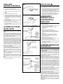 2
2
-
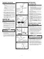 3
3
-
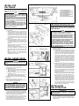 4
4
-
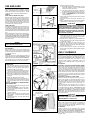 5
5
-
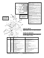 6
6
-
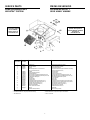 7
7
-
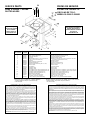 8
8


Broan 402101 Manual de usuario
- Categoría
- Campanas de cocina
- Tipo
- Manual de usuario
en otros idiomas
- English: Broan 402101 User manual
