
INSTRUCTION MANUAL
MANUAL DE INSTRUCCIONES
Cordless Hole Puncher
Perforador Inalámbrico
XPP01
Read before use.
Lea antes de usar.

2 ENGLISH
ENGLISH (Original instructions)
SPECIFICATIONS
Model: XPP01
Max. throat depth 40 mm (1-37/64″)
Shape of holes Round / Oblong
Max. hole size and thickness For mild steel of 65,000 psi
tensile strength
Diameter : 20 mm (25/32″)
Thickness : 8 mm (5/16″)
For stainless steel of 89,000 psi
tensile strength
Diameter : 20 mm (25/32″)
Thickness : 6 mm (15/64″)
Rated voltage D.C. 18 V
Dimensions (L x W x H)
(with handle)
417 mm x 127 mm x 315 mm
(16-27/64″ x 5″ x 12-13/32″)
Net weight 10.7 - 10.8 kg (23.6 - 23.8 lbs)
• Due to our continuing program of research and development, the specications herein are subject to change
without notice.
• Specications may differ from country to country.
• Weight, with battery cartridge, according to EPTA-Procedure 01/2014
Applicable battery cartridge and charger
Battery cartridge BL1830B / BL1840B / BL1850B / BL1860B
Charger DC18RC / DC18RD / DC18RE / DC18SD / DC18SE / DC18SF
• Some of the battery cartridges and chargers listed above may not be available depending on your region of
residence.
WARNING: Only use the battery cartridges and chargers listed above. Use of any other battery cartridges
and chargers may cause injury and/or re.

3 ENGLISH
Combination of punch and die
Round punching
Punch Die Workpiece Capacity
Flat bar Max: 80 mm (3-5/32″) x t8
(Center punching)
Angle
Min: 40 mm (1-37/64″) x 40 mm (1-37/64″) x t3
Max: 80 mm (3-5/32″) x 80 mm (3-5/32″) x t8
Channel
Min: 75 mm (2-61/64″) x 40 mm (1-37/64″)
Max: 100 mm (3-15/16″) x 50 mm (1-31/32″)
(Flange punching)
Unit: mm
Punch Die Tensile Channel Tensile
Mild Steel (65,000 psi) Stainless Steel (89,000
psi)
6
(15/64″)
SB6
(15/64″-SB) t2 - t4 - t3 - t4
6.5
(1/4″)
SB6.5
(1/4″-SB) t2 - t6 - t3 - t4
8
(5/16″)
SB8
(5/16″-SB) t2 - t6 - t3 - t4
8.5
(11/32″)
SB8.5
(11/32″-SB) t2 - t6 - t3 - t4
10
(3/8″)
SB10
(3/8″-SB) t2 - t6 t7.5 t3 - t4
11
(7/16″)
SB11
(7/16″-SB) t2 - t8 t7.5 t3 - t6
12
(15/32″)
SB12
(15/32″-SB) t2 - t8 t7.5 t3 - t6
13
(1/2″)
SB13
(1/2″-SB) t2 - t8 t7.5 t3 - t6
14
(9/16″)
SB14
(9/16″-SB) t2 - t8 t7.5 t3 - t6
15
(19/32″)
SB15
(19/32″-SB) t2 - t8 t7.5 t3 - t6
16
(5/8″)
SB16
(5/8″-SB) t2 - t8 t7.5 t3 - t6
18
(23/32″)
SB18
(23/32″-SB) t2 - t8 t7.5 t3 - t6
19
(3/4″)
SB19
(3/4″-SB) t2 - t8 t7.5 t3 - t6
20
(25/32″)
SB20
(25/32″-SB) t2 - t8 t7.5 t3 - t6

4 ENGLISH
Oblong punching
Punch Die Workpiece Capacity
Flat bar Max: 80 mm (3-5/32″) x t8
(Center punching)
Angle
Min: 40 mm (1-37/64″) x 40 mm (1-37/64″) x t3
Max: 80 mm (3-5/32″) x 80 mm (3-5/32″) x t8
Channel
Min: 75 mm (61/64″) x 40 mm (1-37/64″)
Max: 100 mm (3-15/16″) x 50 mm (1-31/32″)
(Flange punching)
Unit: mm
Punch Die Tensile Channel Tensile
Mild Steel (65,000 psi) Stainless Steel (89,000
psi)
6.5 x 10
(1/4″ x 3/8″)
6.5 x 10B
(1/4″ x 3/8″-B) t2 - t6 - t3 - t4
6.5 x 13
(1/4″ x 1/2″)
6.5 x 13B
(1/4″ x 1/2″-B) t2 - t6 - t3 - t4
8.5 x 13
(11/32″ x 1/2″)
8.5 x 13B
(11/32″ x 1/2″-B) t2 - t6 - t3 - t4
8.5 x 17
(11/32″ x 43/64″)
8.5 x 17B
(11/32″ x 43/64″-B) t2 - t6 - t3 - t4
9 x 13.5
(23/64″ x 17/32″)
9 x 13.5B
(23/64″ x 17/32″-B) t2 - t6 - t3 - t4
9 x 18
(23/64″ x 23/32″)
9 x 18B
(23/64″ x 23/32″-B) t2 - t6 - t3 - t4
10 x 15
(3/8″ x 19/32″)
10 x 15B
(3/8″ x 19/32″-B) t2 - t8 t7.5 t3 - t6
10 x 20
(3/8″ x 25/32″)
10 x 20B
(3/8″ x 25/32″-B) t2 - t8 t7.5 t3 - t6
11 x 16.5
(7/16″ x 21/32″)
11 x 16.5B
(7/16″ x 21/32″-B) t2 - t8 t7.5 t3 - t6
12 x 18
(15/32″ x 23/32″)
12 x 18B
(15/32″ x 23/32″-B) t2 - t8 t7.5 t3 - t6
13 x 19.5
(1/2″ x 49/64″)
13 x 19.5B
(1/2″ x 49/64″-B) t2 - t8 t7.5 t3 - t6
14 x 21
(9/16″ x 53/64″)
14 x 21B
(9/16″ x 53/64″-B) t2 - t8 t7.5 t3 - t6
Symbols
The followings show the symbols used for the equip-
ment. Be sure that you understand their meaning before
use.
Read instruction manual.
Flying debris and loud noise hazards. Wear
ear and eye protection.
Hazardous voltage. Disconnect all power
before working on this equipment. Failure
to observe this instruction may result in
death or personal injury.
Moving blade. Keep hands clear while
machine is operating. Turn power off
before servicing.

5 ENGLISH
Ni-MH
Li-ion
Only for EU countries
Do not dispose of electric equipment or
battery pack together with household waste
material!
In observance of the European Directives,
on Waste Electric and Electronic
Equipment and Batteries and Accumulators
and Waste Batteries and Accumulators
and their implementation in accordance
with national laws, electric equipment and
batteries and battery pack(s) that have
reached the end of their life must be col-
lected separately and returned to an envi-
ronmentally compatible recycling facility.
SAFETY WARNINGS
General power tool safety warnings
WARNING: Read all safety warnings, instruc-
tions, illustrations and specications provided
with this power tool. Failure to follow all instructions
listed below may result in electric shock, re and/or
serious injury.
Save all warnings and instruc-
tions for future reference.
The term "power tool" in the warnings refers to your
mains-operated (corded) power tool or battery-operated
(cordless) power tool.
Work area safety
1. Keep work area clean and well lit. Cluttered or
dark areas invite accidents.
2. Do not operate power tools in explosive atmo-
spheres, such as in the presence of ammable
liquids, gases or dust. Power tools create sparks
which may ignite the dust or fumes.
3. Keep children and bystanders away while
operating a power tool. Distractions can cause
you to lose control.
Electrical Safety
1. Power tool plugs must match the outlet. Never
modify the plug in any way. Do not use any
adapter plugs with earthed (grounded) power
tools. Unmodied plugs and matching outlets will
reduce risk of electric shock.
2. Avoid body contact with earthed or grounded
surfaces, such as pipes, radiators, ranges and
refrigerators. There is an increased risk of elec-
tric shock if your body is earthed or grounded.
3. Do not expose power tools to rain or wet con-
ditions. Water entering a power tool will increase
the risk of electric shock.
4. Do not abuse the cord. Never use the cord for
carrying, pulling or unplugging the power tool.
Keep cord away from heat, oil, sharp edges
or moving parts. Damaged or entangled cords
increase the risk of electric shock.
5. When operating a power tool outdoors, use an
extension cord suitable for outdoor use. Use of
a cord suitable for outdoor use reduces the risk of
electric shock.
6. If operating a power tool in a damp location is
unavoidable, use a ground fault circuit inter-
rupter (GFCI) protected supply. Use of a GFCI
reduces the risk of electric shock.
7.
Power tools can produce electromagnetic elds
(EMF) that are not harmful to the user. However,
users of pacemakers and other similar medical
devices should contact the maker of their device and/
or doctor for advice before operating this power tool.
Personal Safety
1. Stay alert, watch what you are doing and use
common sense when operating a power tool.
Do not use a power tool while you are tired or
under the inuence of drugs, alcohol or med-
ication. A moment of inattention while operating
power tools may result in serious personal injury.
2. Use personal protective equipment. Always
wear eye protection. Protective equipment such
as dust mask, non-skid safety shoes, hard hat, or
hearing protection used for appropriate conditions
will reduce personal injuries.
3. Prevent unintentional starting. Ensure the
switch is in the off-position before connecting
to power source and/or battery pack, picking
up or carrying the tool. Carrying power tools with
your nger on the switch or energising power tools
that have the switch on invites accidents.
4. Remove any adjusting key or wrench before
turning the power tool on. A wrench or a key left
attached to a rotating part of the power tool may
result in personal injury.
5. Do not overreach. Keep proper footing and
balance at all times. This enables better control
of the power tool in unexpected situations.
6. Dress properly. Do not wear loose clothing or
jewellery. Keep your hair, clothing and gloves
away from moving parts. Loose clothes, jewel-
lery or long hair can be caught in moving parts.
7. If devices are provided for the connection of
dust extraction and collection facilities, ensure
these are connected and properly used. Use of
dust collection can reduce dust-related hazards.
8. Do not let familiarity gained from frequent use
of tools allow you to become complacent and
ignore tool safety principles. A careless action
can cause severe injury within a fraction of a
second.
9. Always wear protective goggles to protect
your eyes from injury when using power tools.
The goggles must comply with ANSI Z87.1 in
the USA.
It is an employer's responsibility to enforce the
use of appropriate safety protective equipment
by the tool operators and by other persons in
the immediate working area.
Power tool use and care
1. Do not force the power tool. Use the correct
power tool for your application. The correct
power tool will do the job better and safer at the
rate for which it was designed.
2. Do not use the power tool if the switch does
not turn it on and off. Any power tool that cannot
be controlled with the switch is dangerous and
must be repaired.

6 ENGLISH
3. Disconnect the plug from the power source
and/or remove the battery pack, if detachable,
from the power tool before making any adjust-
ments, changing accessories, or storing power
tools. Such preventive safety measures reduce
the risk of starting the power tool accidentally.
4. Store idle power tools out of the reach of chil-
dren and do not allow persons unfamiliar with
the power tool or these instructions to operate
the power tool. Power tools are dangerous in the
hands of untrained users.
5. Maintain power tools and accessories. Check
for misalignment or binding of moving parts,
breakage of parts and any other condition that
may affect the power tool’s operation. If dam-
aged, have the power tool repaired before use.
Many accidents are caused by poorly maintained
power tools.
6. Keep cutting tools sharp and clean. Properly
maintained cutting tools with sharp cutting edges
are less likely to bind and are easier to control.
7. Use the power tool, accessories and tool bits
etc. in accordance with these instructions, tak-
ing into account the working conditions and
the work to be performed. Use of the power tool
for operations different from those intended could
result in a hazardous situation.
8. Keep handles and grasping surfaces dry,
clean and free from oil and grease. Slippery
handles and grasping surfaces do not allow for
safe handling and control of the tool in unexpected
situations.
9. When using the tool, do not wear cloth work
gloves which may be entangled. The entangle-
ment of cloth work gloves in the moving parts may
result in personal injury.
Battery tool use and care
1. Recharge only with the charger specied by
the manufacturer. A charger that is suitable for
one type of battery pack may create a risk of re
when used with another battery pack.
2. Use power tools only with specically desig-
nated battery packs. Use of any other battery
packs may create a risk of injury and re.
3. When battery pack is not in use, keep it away
from other metal objects, like paper clips,
coins, keys, nails, screws or other small metal
objects, that can make a connection from one
terminal to another. Shorting the battery termi-
nals together may cause burns or a re.
4. Under abusive conditions, liquid may be
ejected from the battery; avoid contact. If con-
tact accidentally occurs, ush with water. If
liquid contacts eyes, additionally seek medical
help. Liquid ejected from the battery may cause
irritation or burns.
5. Do not use a battery pack or tool that is dam-
aged or modied. Damaged or modied batteries
may exhibit unpredictable behaviour resulting in
re, explosion or risk of injury.
6. Do not expose a battery pack or tool to re or
excessive temperature. Exposure to re or tem-
perature above 130 °C may cause explosion.
7. Follow all charging instructions and do not
charge the battery pack or tool outside the
temperature range specied in the instruc-
tions. Charging improperly or at temperatures
outside the specied range may damage the
battery and increase the risk of re.
Service
1. Have your power tool serviced by a qualied
repair person using only identical replacement
parts. This will ensure that the safety of the power
tool is maintained.
2. Never service damaged battery packs. Service
of battery packs should only be performed by the
manufacturer or authorized service providers.
3. Follow instruction for lubricating and chang-
ing accessories.
4. Do not modify or attempt to repair the appli-
ance or the battery pack except as indicated in
the instructions for use and care.
Safety instructions for Cordless
Hole Puncher
1. Proper selection of the punch and the die is
essential. Select the correct punch and die
according to the hole shape, size of hole,
workpiece thickness and material type.
2. Ensure that any punch with stepped edge,
which prevents free rotation, is installed cor-
rectly in the punch piston before tightening the
punch retaining nut.
3. For punching channel-shaped workpiece and
the workpiece made of stainless steel, use the
die provided exclusively for these materials.
Only select the combination of the punch
and die that is suitable for the workpiece
thickness.
4. Ensure the punch and the die are rmly xed
in position with the nut or the bolt. Failure to
do so may cause serious damage to your tool
and serious personal injury. Regularly check and
tighten the punch and die.
5. The tool is electro-hydraulic. When the tem-
perature is cold, it should be run for a few
minutes at idle before starting operations.
6. Keep face, hands and other parts of your body
away from the punching area during operation.
7. Remove the battery cartridge before changing
the punch and the die or when servicing or
making adjustments.
8. The punch and the die that become worn,
deformed, nicked, broken or damaged in any
way may cause a tool breakdown and a seri-
ous accident. Replace them immediately with
new ones supplied from Makita.
9. When punching stainless steel, the punch
and die may wear earlier than punching softer
materials. Ensure that the punch and die are
in good condition, free from wear and are not
deformed, nicked, broken or damaged in any
way. Check with your dealer before punching
any material not listed in the specications.

7 ENGLISH
10. Remove and check the carbon brushes reg-
ularly. Replace them after 200 times of use.
Carbon brushes with a length of about 6 mm
(15/64″) or less may cause damage to the motor.
11. When using the tool continuously, its tempera-
ture can exceed 70 °C which may cause lower
performance. In this case, stop operating for
about 1 hour to allow the tool to cool down
before using it again.
12. Do not cover or clog the motor air vents as this
may cause the motor to overheat, resulting in
smoke, re and explosion.
Symbols
The followings show the symbols used for tool.
volts
direct current
diameter
Important safety instructions for
battery cartridge
1. Before using battery cartridge, read all instruc-
tions and cautionary markings on (1) battery
charger, (2) battery, and (3) product using
battery.
2. Do not disassemble battery cartridge.
3. If operating time has become excessively
shorter, stop operating immediately. It may
result in a risk of overheating, possible burns
and even an explosion.
4. If electrolyte gets into your eyes, rinse them
out with clear water and seek medical atten-
tion right away. It may result in loss of your
eyesight.
5. Do not short the battery cartridge:
(1) Do not touch the terminals with any con-
ductive material.
(2) Avoid storing battery cartridge in a con-
tainer with other metal objects such as
nails, coins, etc.
(3) Do not expose battery cartridge to water
or rain.
A battery short can cause a large current
ow, overheating, possible burns and even a
breakdown.
6. Do not store the tool and battery cartridge in
locations where the temperature may reach or
exceed 50 °C (122 °F).
7. Do not incinerate the battery cartridge even if
it is severely damaged or is completely worn
out. The battery cartridge can explode in a re.
8. Be careful not to drop or strike battery.
9. Do not use a damaged battery.
10. The contained lithium-ion batteries are subject
to the Dangerous Goods Legislation require-
ments.
For commercial transports e.g. by third parties,
forwarding agents, special requirement on pack-
aging and labeling must be observed.
For preparation of the item being shipped, consult-
ing an expert for hazardous material is required.
Please also observe possibly more detailed
national regulations.
Tape or mask off open contacts and pack up the
battery in such a manner that it cannot move
around in the packaging.
11. When disposing the battery cartridge, remove
it from the tool and dispose of it in a safe
place. Follow your local regulations relating to
disposal of battery.
12. Use the batteries only with the products
specied by Makita. Installing the batteries to
non-compliant products may result in a re, exces-
sive heat, explosion, or leak of electrolyte.
13. If the tool is not used for a long period of time,
the battery must be removed from the tool.
SAVE THESE INSTRUCTIONS.
CAUTION: Only use genuine Makita batteries.
Use of non-genuine Makita batteries, or batteries that
have been altered, may result in the battery bursting
causing res, personal injury and damage. It will
also void the Makita warranty for the Makita tool and
charger.
Tips for maintaining maximum
battery life
1. Charge the battery cartridge before completely
discharged. Always stop tool operation and
charge the battery cartridge when you notice
less tool power.
2. Never recharge a fully charged battery car-
tridge. Overcharging shortens the battery
service life.
3. Charge the battery cartridge with room tem-
perature at 10 °C - 40 °C (50 °F - 104 °F). Let
a hot battery cartridge cool down before
charging it.
4. Charge the battery cartridge if you do not use
it for a long period (more than six months).

8 ENGLISH
PARTS DESCRIPTION
1
3
4
5
2
6
7
8
9
10
11
12
14
13
1 Motor 2 Safety label 3 Pump case 4 Punch retaining nut
5 Punch 6 Die 7 Stripper 8 C frame
9 Slide stopper 10 Return lever 11 Oil port 12 Switch trigger
13 Trigger lock button 14 Battery cartridge - - - -

9 ENGLISH
FUNCTIONAL
DESCRIPTION
CAUTION: Always be sure that the tool is
switched off and the battery cartridge is removed
before adjusting or checking function on the tool.
Installing or removing battery
cartridge
CAUTION: Always switch off the tool before
installing or removing of the battery cartridge.
CAUTION: Hold the tool and the battery car-
tridge rmly when installing or removing battery
cartridge. Failure to hold the tool and the battery
cartridge rmly may cause them to slip off your hands
and result in damage to the tool and battery cartridge
and a personal injury.
1
2
3
► 1. Red indicator 2. Button 3. Battery cartridge
To remove the battery cartridge, slide it from the tool
while sliding the button on the front of the cartridge.
To install the battery cartridge, align the tongue on the
battery cartridge with the groove in the housing and slip
it into place. Insert it all the way until it locks in place
with a little click. If you can see the red indicator on the
upper side of the button, it is not locked completely.
CAUTION: Always install the battery cartridge
fully until the red indicator cannot be seen. If not,
it may accidentally fall out of the tool, causing injury to
you or someone around you.
CAUTION: Do not install the battery cartridge
forcibly. If the cartridge does not slide in easily, it is
not being inserted correctly.
Battery protection system
The tool is equipped with a battery protection system.
This system automatically cuts off power to the motor to
extend tool and battery life. The tool will automatically
stop during operation if the tool or battery is placed
under the following condition.
Overdischarge protection
When the battery capacity is not enough, the tool stops
automatically. In this case, remove the battery from the
tool and charge the battery.
Indicating the remaining battery
capacity
Only for battery cartridges with the indicator
1
2
► 1. Indicator lamps 2. Check button
Press the check button on the battery cartridge to indi-
cate the remaining battery capacity. The indicator lamps
light up for a few seconds.
Indicator lamps Remaining
capacity
Lighted Off Blinking
75% to 100%
50% to 75%
25% to 50%
0% to 25%
Charge the
battery.
The battery
may have
malfunctioned.
NOTE: Depending on the conditions of use and the
ambient temperature, the indication may differ slightly
from the actual capacity.

10 ENGLISH
Switch action
CAUTION: Before installing the battery car-
tridge into the tool, always check to see that the
switch trigger actuates properly and returns to
the "OFF" position when released.
CAUTION: Always lock the switch trigger
when not in use.
When punching a workpiece, continue to pull the switch
trigger until the punch goes down to the die and returns
to the start position.
To lock the switch trigger, push in the trigger lock button
from B side. To unlock, push in the trigger lock button
from A side
1
2
► 1. Trigger lock button 2. Switch trigger
Rotatable grip
The grip can be rotated though 360 degrees, in either
direction, during operation. This feature is particularly
useful when working in awkward or narrow areas as it
allows the operator to position the tool in the best posi-
tion for easy operation.
ASSEMBLY
CAUTION: Always be sure that the tool is
switched off and the battery cartridge is removed
before carrying out any work on the tool.
Replacing the punch and die
Replacing round punch
1
2
3
4
1
► 1. Stripper 2. Nut and set bolt 3. Punch retaining nut
4. Round punch
1. Be sure that the punch piston is fully retracted and
remove the strippers to make access to the parts easier.
2. The punch must be removed rst and then the die.
Unscrew the punch retaining nut to remove the punch
and remove the set bolt and the nut to remove the die.
NOTICE: When replacing the punch and the die,
make sure that the correct size, thickness and
hole shape is selected. Shaped punches and dies
must be properly aligned with each other.
3. Place the die in the C frame in the proper orienta-
tion. Secure rmly with the set bolt and tighten the nut.
4. Place the punch in the punch retaining nut. Insert
the punch with the nut into the punch piston and hand
tighten the nut.
NOTICE: When installing a punch with a stepped
edge (anti rotation), make sure the orientation
is correct and that the stepped edge is correctly
positioned in the punch piston.

11 ENGLISH
5. Make sure the punch is correctly positioned in the
punch rod and tighten the punch retaining nut rmly with
the nut retaining bar supplied.
1
2
3
4
► 1. Nut retaining bar 2. Punch retaining nut
3. Loosen 4. Tighten
6. Restore the strippers.
WARNING: If the punch and die are not
the same size or the punch and the die are not
positioned properly, the punch may strike the
die causing both parts to break. In such a case,
pieces ying off from the broken parts may cause
personal injury.
CAUTION: Check the buttery bolts which
hold the stripper regularly to ensure that they are
tight. Loose bolts may cause the stripper to come
off and damage the tool.
Replacing oblong punch
1
2
3
4
1
4
6
5
► 1. Stripper 2. Nut and set bolt 3. Punch retaining nut
4. Oblong punch 5. Stepped edge 6. Punch rod
1. Be sure that the punch piston is fully retracted and
remove the strippers to make access to the parts easier.
2. The punch must be removed rst and then the die.
Unscrew the punch retaining nut to remove the punch
and remove the set bolt and the nut to remove the die.
NOTICE: When replacing the punch and the die,
make sure that the correct size, thickness and
hole shape is selected. Shaped punches and dies
must be properly aligned with each other.
3. Secure the oblong die rmly with the set bolt and
tighten the nut.
4. Place the oblong punch into the punch retaining
nut. Position the stepped edge of the oblong punch
properly in the punch piston and hand tighten the punch
retaining nut.
NOTICE: If the stepped edge of the oblong
punch is not properly inserted into the punch
piston, the punch retaining nut cannot be fas-
tened. Make sure the oblong punch is positioned
correctly in the punch rod.
5. Push the oblong punch against the punch rod and
tighten the punch retaining nut rmly with the nut rmly
with the nut retaining bar supplied.
1
2
3
4
► 1. Nut retaining bar 2. Punch retaining nut
3. Loosen 4. Tighten
6. Restore the strippers.
WARNING: If the punch and die are not
the same size or the punch and the die are not
positioned properly, the punch may strike the
die causing both parts to break. In such a case,
pieces ying off from the broken parts may cause
personal injury.
CAUTION: Check the buttery bolts which
hold the stripper regularly to ensure that they are
tight. Loose bolts may cause the stripper to come
off and damage the tool.
CAUTION: Make sure the stepped edge of
the oblong punch is positioned correctly in the
punch rod and the punch retaining nut is properly
fastened.

12 ENGLISH
OPERATION
Correct use of the tool
Die selection
It is important that the die to be used is correct for the
thickness of the workpiece to be punched. Punching the
workpiece of 4 mm (5/32″) to 8 mm (5/16″) thickness
using a die for thinner workpiece can cause the punch
to jam in the workpiece. This is due to the smaller clear-
ance between the die and punch. In such a case, the
workpiece will be pulled up by the retracting punch as
shown in the gure. Special care should be taken when
punching at bar of mild steel, aluminum and copper.
1
► 1. Workpiece
Correct use of the stripper
Do not position the workpiece with one end or both
ends unsupported by the stripper. If the workpiece is not
properly supported, it will move when the punch returns.
It may cause the punch to jam and damaging the tool.
1
2
► 1. Stripper 2. Workpiece
Punching a hole
CAUTION: Before punching, always make
sure that the proper punch and die are installed
correctly.
1. Check the position for punching.
1
2
3
1
► 1. Punch 2. Flat bar 3. Die
2. Loosen the cap screw on the slide stopper and
adjust the slide stopper to the desired position. After
that, retighten the cap screw.
NOTE: The slide stopper is set to hold the hole
puncher at a constant distance from the edge of the
work piece.
3. Check that the return lever is fully closed in the
clockwise direction.
1
2
3
4
► 1. Spring pin 2. Return lever 3. Open position
4. Closed position
4. Check that the punch piston is fully retracted.
5. Place the puncher in the required position on the
workpiece using the slide stopper as a guide. Align the
point of the punch with the center mark of the hole to be
punched.

13 ENGLISH
6.
Continue to pull the switch trigger until the punch reaches
the end of its stroke and returns to the starting position.
The punch rod will extend and push the punch through
the workpiece.
NOTE:
To aid accurate and easy positioning of the punch,
pull the switch trigger intermittently to jog the punch down
to the workpiece. If the position is not satisfactory, open
the return lever to retract the punch for another attempt. If
the punch doesn’t return to its starting position with return
lever open, pull the switch trigger to return the punch.
NOTE: If the punch doesn’t return after punching
nishes, release the switch trigger to stop the motor
and pull the switch trigger again.
If the punch doesn’t return even after performing above
procedures, perform the procedures for stopping the oper-
ation before the completion of punching mentioned below.
Stopping the operation before the
punching is nished
If you want to stop the operation before the punching is
nished, perform the procedures below:
1.
Turn the return lever counterclockwise until it hits the
spring pin and then immediately back to its starting position.
Doing this releases the internal pressure of the tool. If
the punch retracts from the workpiece under its own
power, allow the punch to fully return. After that, turn the
return lever back to its starting position. In this case, the
following step is not necessary.
2. Continue to pull the switch trigger until the punch
returns to its starting position.
Using slide stopper for maximum depth
Optional accessory
CAUTION: Before attaching or removing the
slide stopper, ensure that the battery cartridge
is removed to prevent accidental operation and
personal injury.
Punching up to 40 mm (1-37/64″) depth from the edge of the
workpiece can be done using the optional slide stopper.
1
2
► 1. Bolt and washer 2. Optional slide stopper
1. Loosen the set bolt and nut to remove the die.
2.
Remove the bolt and washer xing the slide stopper.
3. Remove the slide stopper by pulling it to the upper
side of the C frame.
4. Insert the optional slide stopper for maximum
depth from the bottom side of the C frame.
5. Fix the optional slide stopper with the bolt and
washer removed in step 2.
6.
Install the die with the set bolt and nut removed in step 1.
MAINTENANCE
CAUTION: Always be sure that the tool is
switched off and the battery cartridge is removed
before attempting to perform inspection or
maintenance.
NOTICE: Never use gasoline, benzine, thinner,
alcohol or the like. Discoloration, deformation or
cracks may result.
To maintain product SAFETY and RELIABILITY,
repairs, any other maintenance or adjustment should
be performed by Makita Authorized or Factory Service
Centers, always using Makita replacement parts.
Regular maintenance
Keep the air hole at the end of the C frame clear of dirt
and obstructions. The air hole has to be open in order to
control the hydraulic pressure.
1
► 1. Air hole
Do not undo or remove the three screws as shown in
the gure. Doing so will cause oil to leak from the tool.

14 ENGLISH
Addling oil
This tool is electro-hydraulic. When shipped from the
factory, it was lled with the oil. Do not attempt to add oil
as long as the tool performs well. When the oil-pressure
is not enough for proper operation, add oil in the follow-
ing procedures.
NOTICE: Make sure that the work area and all
equipment is clean so that no dirt, dust or other
foreign materials can get into the hydraulic oil or
pump area.
NOTICE: Only use pure hydraulic oil recom-
mended by Makita. To prevent damage to the seals
and other internal machine parts, do not use other oil
listed below.
Recommended oil:
• Makita hydraulic oil
• Super Hyrando #46 (JXTG Nippon Oil & Energy
Corp.)
• Shell Tellus Plus #46 (U.S. Shell)
• Hydraulic oil with equivalent spec anti-wear, ISO
Viscosity Grade 46.
1. Install the battery cartridge to the tool.
2. Lay the tool on its left side so that the oil port is
facing up.
3. Operate the tool to move the punch position
almost to the bottom of its stroke.
NOTE: If necessary, run the tool for several strokes.
Doing so allows you to determine the bottom of stroke
and also position the punch piston correctly. In the
correct position, the maximum amount of oil has been
drawn from the pump and the appropriate amount of
oil for rell can be obtained.
4. Remove the battery cartridge from the tool.
5. Carefully remove the socket head cap screw to
open the oil port.
1
► 1. Socket head cap screw
6. Fill the reservoir with hydraulic oil using the small
squeeze bottle which is supplied with the tool.
7. Rock the tool back and forth slightly several times
to free any trapped air bubbles. After that, add addi-
tional oil as necessary.
8. Replace the socket head cap screw and wipe up
any excess oil.
9. Install the battery cartridge and run the tool for
several strokes with the return lever is in open position.
After that, run the tool again with the return lever is in
closed position.
Doing this purges trapped air out of the system. Repeat
this procedure to make sure that the punch piston is
almost at the bottom of its stroke.
10. Add additional oil as necessary by repeating step
3 to 9.
If the oil is depleted excessively, you need to repeat this
procedure several times.
Replacing carbon brushes
Replace the carbon brushes when they wear down to
the limit mark.
NOTICE: Keep the carbon brushes clean and
free to slip in the holders.
NOTICE: Both carbon brushes must be replaced
at the same time.
NOTICE: Use only identical carbon brushes.
1
► 1. Limit mark
1. Remove two screws on the rear cover using a
screwdriver and then remove the rear cover.
2
1
► 1. Rear cover 2. Screw

15 ENGLISH
2. Raise the arm part of the spring and then place
it in the recessed part of the housing with a slotted bit
screwdriver or the like.
1
2 3
► 1. Arm 2. Spring 3. Recessed part
3. Remove the carbon brush caps of the carbon
brushes using pliers and then take out the worn carbon
brushes. Insert the new carbon brushes and attach the
carbon brush caps.
1
► 1. Carbon brush cap
4. Make sure that the carbon brush caps have t into
the holes in brush holders securely.
1
2
► 1. Hole 2. Carbon brush cap
5. Reinstall the rear cover and tighten two screws
securely.

16 ENGLISH
TROUBLESHOOTING
Before asking for repairs, conduct your own inspection rst. If you nd a problem that is not explained in the manual,
do not attempt to dismantle the tool. Instead, ask Makita Authorized Service Centers, always using Makita replace-
ment parts for repairs.
State of abnormality Probable cause (malfunction) Remedy
Punch piston will not come out. Oil is insufcient Rell oil.
Punch piston has not returned com-
pletely due to rebar chips, iron powder
and dirt in the sliding portion of punch
piston and C frame.
Push back punch piston.
Clean punch piston.
Punch piston has not returned com-
pletely due to the distortion or swelling
of punch piston.
Ask your local authorized service center for repair.
Punch piston has not returned com-
pletely due to weak return spring.
Ask your local authorized service center for repair.
Although punch piston comes out,
cutting power is too weak to hole
punching.
Oil is insufcient. Rell oil.
Contact between cylinder and release
valve is improper. There may be
scratches at chimney of cylinder or iron
powder or dirt are sticking there.
Ask your local authorized service center for repair.
Breakage of release valve. Ask your local authorized service center for repair.
Improper clearance between cylinder
and piston.
Ask your local authorized service center for repair.
Improper contact between cylinder and
check valve.
Ask your local authorized service center for repair.
Breakage of urethane packing of
cylinder.
Ask your local authorized service center for repair.
Oil leaks. Scratches on or breakage of oil leveler
sack.
Ask your local authorized service center for repair.
Scratches at sliding portion of C frame
and punch piston and at back-up ring.
Ask your local authorized service center for repair.
Breakage of O-ring at joint of C frame
and cylinder.
Ask your local authorized service center for repair.
Breakage of liner at joint of cylinder and
pump case.
Ask your local authorized service center for repair.
Insufcient tightening of bolts at respec-
tive parts.
Tighten bolts.
Motor does not move.
Poor motor rotation.
Insufcient charge of battery cartridge. Charge battery cartridge.
Battery life cycle worn off. Replace battery cartridge.
Breakage of motor by overheating. Ask your local authorized service center for repair.
Deformation or breakage of bearings
and gear connected to the motor.
Ask your local authorized service center for repair.
CAUTION: The internal components of the pump have very close clearances and are sensitive to
damage from dust, dirt, contamination of the hydraulic uid or improper handling. The disassembly of the
pump housing requires special tools and training, and should only be attempted by repair personnel who
have been properly trained and have the proper equipment. The improper servicing of electrical compo-
nents can lead to conditions that could cause serious injury. The pump and piston components and all
electrical components should be serviced only by authorized repair shop, dealer or distributor.
NOTICE: Any attempt by unauthorized personnel to service the internal components of the pump area
will void the warranty.

17
OPTIONAL
ACCESSORIES
CAUTION: These accessories or attachments
are recommended for use with your Makita tool
specied in this manual. The use of any other
accessories or attachments might present a risk of
injury to persons. Only use accessory or attachment
for its stated purpose.
If you need any assistance for more details regard-
ing these accessories, ask your local Makita Service
Center.
• Work stand
• Slide stopper (Max. throat depth)
• Makita genuine battery and charger
NOTE: Some items in the list may be included in the
tool package as standard accessories. They may
differ from country to country.
ENGLISH

18 ESPAÑOL
ESPAÑOL (Instrucciones originales)
ESPECIFICACIONES
Modelo: XPP01
Profundidad máx. de garganta 40 mm (1-37/64″)
Forma de los oricios Redonda/oblonga
Tamaño y grosor máximos del
oricio
Para acero suave con una resis-
tencia a la tracción de 65 000 psi
Diámetro: 20 mm (25/32″)
Grosor: 8 mm (5/16″)
Para acero inoxidable con una resis-
tencia a la tracción de 89 000 psi
Diámetro: 20 mm (25/32″)
Grosor: 6 mm (15/64″)
Tensión nominal 18 V c.c.
Dimensions (L x W x H)
(with handle)
417 mm x 127 mm x 315 mm
(16-27/64″ x 5″ x 12-13/32″)
Peso neto 10,7 - 10,8 kg (23,6 - 23,8 lbs)
• Debido a nuestro continuo programa de investigación y desarrollo, las especicaciones aquí incluidas están
sujetas a cambio sin previo aviso.
• Las especicaciones pueden variar de país a país.
• Peso de acuerdo al procedimiento de EPTA-01/2014 incluyendo el cartucho de batería
Cartucho de batería y cargador aplicables
Cartucho de batería BL1830B / BL1840B / BL1850B / BL1860B
Cargador DC18RC / DC18RD / DC18RE / DC18SD / DC18SE / DC18SF
• Algunos de los cartuchos de batería y cargadores enumerados arriba podrían no estar disponibles depen-
diendo de su área de residencia.
ADVERTENCIA: Use únicamente los cartuchos de batería y los cargadores indicados arriba. El uso de
cualquier otro cartucho de batería y cargador podría ocasionar una lesión y/o un incendio.

19 ESPAÑOL
Combinación de punzón y troquel
Perforado redondo
Punzón Troquel Pieza de trabajo Capacidad
Barra plana Máx.: 80 mm (3-5/32″) x t8
(Perforado central)
En ángulo
Mín.: 40 mm (1-37/64″) x 40 mm (1-37/64″) x t3
Máx.: 80 mm (3-5/32″) x 80 mm (3-5/32″) x t8
En canal
Mín.: 75 mm (2-61/64″) x 40 mm (1-37/64″)
Máx.: 100 mm (3-15/16″) x 50 mm (1-31/32″)
(Perforado de reborde)
Unidad: mm
Punzón Troquel Tracción En canal Tracción
Acero suave (65 000
psi)
Acero inoxidable (89
000 psi)
6
(15/64″)
SB6
(15/64″-SB) t2 - t4 - t3 - t4
6.5
(1/4″)
SB6.5
(1/4″-SB) t2 - t6 - t3 - t4
8
(5/16″)
SB8
(5/16″-SB) t2 - t6 - t3 - t4
8.5
(11/32″)
SB8.5
(11/32″-SB) t2 - t6 - t3 - t4
10
(3/8″)
SB10
(3/8″-SB) t2 - t6 t7,5 t3 - t4
11
(7/16″)
SB11
(7/16″-SB) t2 - t8 t7,5 t3 - t6
12
(15/32″)
SB12
(15/32″-SB) t2 - t8 t7,5 t3 - t6
13
(1/2″)
SB13
(1/2″-SB) t2 - t8 t7,5 t3 - t6
14
(9/16″)
SB14
(9/16″-SB) t2 - t8 t7,5 t3 - t6
15
(19/32″)
SB15
(19/32″-SB) t2 - t8 t7,5 t3 - t6
16
(5/8″)
SB16
(5/8″-SB) t2 - t8 t7,5 t3 - t6
18
(23/32″)
SB18
(23/32″-SB) t2 - t8 t7,5 t3 - t6
19
(3/4″)
SB19
(3/4″-SB) t2 - t8 t7,5 t3 - t6
20
(25/32″)
SB20
(25/32″-SB) t2 - t8 t7,5 t3 - t6

20 ESPAÑOL
Perforado oblongo
Punzón Troquel Pieza de trabajo Capacidad
Barra plana Máx.: 80 mm (3-5/32″) x t8
(Perforado central)
En ángulo
Mín.: 40 mm (1-37/64″) x 40 mm (1-37/64″) x t3
Máx.: 80 mm (3-5/32″) x 80 mm (3-5/32″) x t8
En canal
Mín.: 75 mm (61/64″) x 40 mm (1-37/64″)
Máx.: 100 mm (3-15/16″) x 50 mm (1-31/32″)
(Perforado de reborde)
Unidad: mm
Punzón Troquel Tracción En canal Tracción
Acero suave (65 000
psi)
Acero inoxidable (89
000 psi)
6.5 x 10
(1/4″ x 3/8″)
6.5 x 10B
(1/4″ x 3/8″-B) t2 - t6 - t3 - t4
6.5 x 13
(1/4″ x 1/2″)
6.5 x 13B
(1/4″ x 1/2″-B) t2 - t6 - t3 - t4
8.5 x 13
(11/32″ x 1/2″)
8.5 x 13B
(11/32″ x 1/2″-B) t2 - t6 - t3 - t4
8.5 x 17
(11/32″ x 43/64″)
8.5 x 17B
(11/32″ x 43/64″-B) t2 - t6 - t3 - t4
9 x 13.5
(23/64″ x 17/32″)
9 x 13.5B
(23/64″ x 17/32″-B) t2 - t6 - t3 - t4
9 x 18
(23/64″ x 23/32″)
9 x 18B
(23/64″ x 23/32″-B) t2 - t6 - t3 - t4
10 x 15
(3/8″ x 19/32″)
10 x 15B
(3/8″ x 19/32″-B) t2 - t8 t7,5 t3 - t6
10 x 20
(3/8″ x 25/32″)
10 x 20B
(3/8″ x 25/32″-B) t2 - t8 t7,5 t3 - t6
11 x 16.5
(7/16″ x 21/32″)
11 x 16.5B
(7/16″ x 21/32″-B) t2 - t8 t7,5 t3 - t6
12 x 18
(15/32″ x 23/32″)
12 x 18B
(15/32″ x 23/32″-B) t2 - t8 t7,5 t3 - t6
13 x 19.5
(1/2″ x 49/64″)
13 x 19.5B
(1/2″ x 49/64″-B) t2 - t8 t7,5 t3 - t6
14 x 21
(9/16″ x 53/64″)
14 x 21B
(9/16″ x 53/64″-B) t2 - t8 t7,5 t3 - t6
Símbolos
A continuación se muestran los símbolos utilizados
para el equipo. Asegúrese de entender su signicado
antes de usarlo.
Lea el manual de instrucciones.
Riesgo de residuos que salen disparados y
de ruido fuerte. Utilice protección para los
oídos y ojos.
Tensión peligrosa. Desconecte toda
alimentación antes de trabajar en este
equipo. El no seguir estas instrucciones
podría ocasionar la muerte o una lesión
grave.
Disco en movimiento. Mantenga las manos
alejadas mientras la máquina está funcio-
nando. Apague la alimentación antes de
dar servicio.

21 ESPAÑOL
Ni-MH
Li-ion
Exclusivamente para países de la Unión
Europea
¡No deseche ningún equipo eléctrico ni
paquete de batería junto con los residuos
domésticos!
De conformidad con las Directivas
Europeas relativas a los residuos de
equipos eléctricos y electrónicos, bate-
rías y acumuladores y a los residuos de
baterías y acumuladores y su aplicación
de acuerdo con las leyes nacionales, los
equipos eléctricos, baterías y paquetes de
baterías cuya vida útil haya llegado a su n
deberán ser recolectados por separado y
trasladados a una instalación de reciclaje
que cumpla con las normas ambientales.
ADVERTENCIAS DE
SEGURIDAD
Advertencias generales de seguridad
para herramientas eléctricas
ADVERTENCIA: Lea todas las advertencias
de seguridad, instrucciones, ilustraciones y espe-
cicaciones suministradas con esta herramienta
eléctrica. El no seguir todas las instrucciones indi-
cadas a continuación podría ocasionar una descarga
eléctrica, incendio y/o lesiones graves.
Conserve todas las advertencias
e instrucciones como referencia
en el futuro.
En las advertencias, el término “herramienta eléctrica”
se reere a su herramienta eléctrica de funcionamiento
con conexión a la red eléctrica (con cableado eléctrico)
o herramienta eléctrica de funcionamiento a batería
(inalámbrica).
Seguridad en el área de trabajo
1. Mantenga el área de trabajo limpia y bien ilu-
minada. Las áreas oscuras o desordenadas son
propensas a accidentes.
2. No utilice las herramientas eléctricas en
atmósferas explosivas, tal como en la presen-
cia de líquidos, gases o polvo inamables. Las
herramientas eléctricas crean chispas que pueden
prender fuego al polvo o los humos.
3. Mantenga a los niños y curiosos alejados
mientras utiliza una herramienta eléctrica. Las
distracciones le pueden hacer perder el control.
Seguridad eléctrica
1. Las clavijas de conexión de las herramientas
eléctricas deberán encajar perfectamente en la
toma de corriente. No modique nunca la cla-
vija de conexión de ninguna forma. No utilice
ninguna clavija adaptadora con herramientas
eléctricas que tengan conexión a tierra (puesta
a tierra). La utilización de clavijas no modica-
das y que encajen perfectamente en la toma de
corriente reducirá el riesgo de que se produzca
una descarga eléctrica.
2. Evite tocar con el cuerpo supercies conec-
tadas a tierra o puestas a tierra tales como
tubos, radiadores, cocinas y refrigeradores. Si
su cuerpo es puesto a tierra o conectado a tierra
existirá un mayor riesgo de que sufra una des-
carga eléctrica.
3. No exponga las herramientas eléctricas a la
lluvia ni a condiciones húmedas. La entrada de
agua en una herramienta eléctrica aumentará el
riesgo de que se produzca una descarga eléctrica.
4. No maltrate el cable. Nunca utilice el cable
para transportar, jalar o desconectar la herra-
mienta eléctrica. Mantenga el cable alejado del
calor, aceite, objetos cortantes o piezas móvi-
les. Los cables dañados o enredados aumentan
el riesgo de sufrir una descarga eléctrica.
5. Cuando utilice una herramienta eléctrica en
exteriores, utilice un cable de extensión apro-
piado para uso en exteriores. La utilización de
un cable apropiado para uso en exteriores redu-
cirá el riesgo de que se produzca una descarga
eléctrica.
6. Si no es posible evitar usar una herramienta
eléctrica en condiciones húmedas, utilice un
alimentador protegido con interruptor de cir-
cuito de falla a tierra (ICFT). El uso de un ICFT
reduce el riesgo de descarga eléctrica.
7. Las herramientas eléctricas pueden producir
campos electromagnéticos (CEM) que no son
dañinos para el usuario. Sin embargo, si los
usuarios tienen marcapasos y otros dispositivos
médicos similares, deberán consultar al fabricante
de su dispositivo y/o a su médico antes de operar
esta herramienta eléctrica.
Seguridad personal
1. Manténgase alerta, preste atención a lo que
está haciendo y utilice su sentido común
cuando opere una herramienta eléctrica. No
utilice una herramienta eléctrica cuando esté
cansado o bajo la inuencia de drogas, alco-
hol o medicamentos. Un momento de distracción
mientras opera las herramientas eléctricas puede
terminar en una lesión grave.
2. Use equipo de protección personal. Póngase
siempre protección para los ojos. El equipo
protector tal como máscara contra el polvo, zapa-
tos de seguridad antiderrapantes, casco rígido y
protección para oídos utilizado en las condiciones
apropiadas reducirá el riesgo de lesiones.
3. Impida el encendido accidental. Asegúrese
de que el interruptor esté en la posición de
apagado antes de conectar a la alimentación
eléctrica y/o de colocar el cartucho de batería,
así como al levantar o cargar la herramienta.
Cargar las herramientas eléctricas con su dedo
en el interruptor o enchufarlas con el interrup-
tor encendido hace que los accidentes sean
comunes.
4. Retire cualquier llave de ajuste o llave de
apriete antes de encender la herramienta. Una
llave de ajuste o llave de apriete que haya sido
dejada puesta en una parte giratoria de la herra-
mienta eléctrica puede ocasionar alguna lesión.

22 ESPAÑOL
5. No utilice la herramienta donde no alcance.
Mantenga los pies sobre suelo rme y el equi-
librio en todo momento. Esto permite un mejor
control de la herramienta eléctrica en situaciones
inesperadas.
6. Use una vestimenta apropiada. No use ropa
suelta ni alhajas. Mantenga el cabello, la ropa
y los guantes alejados de las piezas móviles.
Las prendas de vestir holgadas, las alhajas y
el cabello largo suelto podrían engancharse en
estas piezas móviles.
7.
Si dispone de dispositivos para la conexión de
equipos de extracción y recolección de polvo,
asegúrese de conectarlos y utilizarlos debida-
mente. Hacer uso de la recolección de polvo puede
reducir los riesgos relacionados con el polvo.
8. No permita que la familiaridad adquirida
debido al uso frecuente de las herramientas
haga que se sienta conado e ignore los prin-
cipios de seguridad de las herramientas. Un
descuido podría ocasionar una lesión grave en
una fracción de segundo.
9. Utilice siempre gafas protectoras para prote-
ger sus ojos de lesiones al usar herramientas
eléctricas. Las gafas deben cumplir con la
Norma ANSI Z87.1 en EUA.
Es responsabilidad del empleador imponer
el uso de equipos protectores de seguridad
apropiados a los operadores de la herramienta
y demás personas cerca del área de trabajo.
Mantenimiento y uso de la herramienta eléctrica
1. No fuerce la herramienta eléctrica. Utilice la
herramienta eléctrica correcta para su aplica-
ción. La herramienta eléctrica adecuada hará un
mejor trabajo y de forma más segura a la veloci-
dad para la que ha sido fabricada.
2. No utilice la herramienta eléctrica si el inte-
rruptor no la enciende y apaga. Cualquier
herramienta eléctrica que no pueda ser contro-
lada con el interruptor es peligrosa y debe ser
reemplazada.
3. Desconecte la clavija de la fuente de alimen-
tación y/o retire la batería de la herramienta
eléctrica, en caso de ser removible, antes de
realizar ajustes, cambiar accesorios o almace-
nar las herramientas eléctricas. Tales medidas
de seguridad preventivas reducirán el riesgo
de poner en marcha la herramienta eléctrica de
forma accidental.
4. Guarde la herramienta eléctrica que no use
fuera del alcance de los niños y no permita
que las personas que no están familiarizadas
con ella o con las instrucciones la operen. Las
herramientas eléctricas son peligrosas en manos
de personas que no saben operarlas.
5. Dé mantenimiento a las herramientas eléctri-
cas y los accesorios. Compruebe que no haya
piezas móviles desalineadas o estancadas,
piezas rotas y cualquier otra condición que
pueda afectar al funcionamiento de la herra-
mienta eléctrica. Si la herramienta eléctrica
está dañada, haga que la reparen antes de
utilizarla. Muchos de los accidentes son ocasio-
nados por no dar un mantenimiento adecuado a
las herramientas eléctricas.
6. Mantenga las herramientas de corte limpias
y losas. Si recibe un mantenimiento adecuado
y tiene los bordes alados, es probable que la
herramienta se atasque menos y sea más fácil
controlarla.
7. Utilice la herramienta eléctrica, los accesorios
y las brocas de acuerdo con estas instruccio-
nes, considerando las condiciones laborales
y el trabajo a realizar. Si utiliza la herramienta
eléctrica para realizar operaciones distintas de
las indicadas, podrá presentarse una situación
peligrosa.
8. Mantenga los mangos y supercies de asi-
miento secos, limpios y libres de aceite o
grasa. Los mangos y supercies de asimiento
resbalosos no permiten una manipulación segura
ni el control de la herramienta en situaciones
inesperadas.
9. Cuando vaya a utilizar esta herramienta, evite
usar guantes de trabajo de tela ya que éstos
podrían atorarse. Si los guantes de trabajo de
tela llegaran a atorarse en las piezas móviles,
esto podría ocasionar lesiones personales.
Uso y cuidado de la herramienta a batería
1. Recargue sólo con el cargador especicado
por el fabricante. Un cargador que es adecuado
para un solo tipo de batería puede generar riesgo
de incendio al ser utilizado con otra batería.
2. Utilice las herramientas eléctricas solamente
con las baterías designadas especícamente
para ellas. La utilización de cualquier otra batería
puede crear un riesgo de lesiones o incendio.
3. Cuando no se esté usando la batería, mantén-
gala alejada de otros objetos metálicos, como
sujetapapeles (clips), monedas, llaves, clavos,
tornillos u otros objetos pequeños de metal
los cuales pueden actuar creando una cone-
xión entre las terminales de la batería. Originar
un cortocircuito en las terminales puede causar
quemaduras o incendios.
4. En condiciones abusivas, podrá escapar
líquido de la batería; evite tocarlo. Si lo toca
accidentalmente, enjuague con agua. Si hay
contacto del líquido con los ojos, busque asis-
tencia médica. Puede que el líquido expulsado
de la batería cause irritación o quemaduras.
5. No utilice una herramienta ni una batería que
estén dañadas o hayan sido modicadas. Las
baterías dañadas o modicadas podrían oca-
sionar una situación inesperada provocando un
incendio, explosión o riesgo de lesiones.
6. No exponga la herramienta ni la batería al
fuego ni a una temperatura excesiva. La expo-
sición al fuego o a una temperatura superior a los
130 °C podría causar una explosión.
7. Siga todas las instrucciones para la carga y
evite cargar la herramienta o la batería fuera
del rango de temperatura especicado en
las instrucciones. Una carga inadecuada o a
una temperatura fuera del rango especicado
podría dañar la batería e incrementar el riesgo de
incendio.

23 ESPAÑOL
Servicio
1. Haga que una persona calicada repare la
herramienta eléctrica utilizando sólo piezas de
repuesto idénticas. Esto asegura que se man-
tenga la seguridad de la herramienta eléctrica.
2. Nunca dé servicio a baterías que estén daña-
das. El servicio a las baterías solamente deberá
ser efectuado por el fabricante o un agente de
servicio autorizado.
3. Siga las instrucciones para la lubricación y
cambio de accesorios.
4. No modique ni intente reparar el aparato ni el
paquete de baterías salvo como se indique en
las instrucciones para el uso y cuidado.
Instrucciones de seguridad para
Perforador Inalámbrico
1. Es esencial la selección adecuada del punzón
y el troquel. Seleccione el punzón y el troquel
correctos de acuerdo con la forma y el tamaño
del oricio, el grosor de la pieza de trabajo y el
tipo de material.
2. Asegúrese de que cualquier punzón con borde
escalonado, que evita la rotación libre, quede
instalado correctamente en el pistón del pun-
zón antes de apretar la tuerca de retención del
punzón.
3. Para perforar la pieza de trabajo en forma de
canal y la pieza de trabajo de acero inoxidable,
use el troquel especícamente para estos
materiales. Seleccione solo la combinación del
punzón y el troquel que sea adecuada para el
grosor de la pieza de trabajo.
4. Asegúrese de que el punzón y el troquel estén
jados con rmeza en posición con la tuerca
o el perno. El no hacerlo podría causar daños
graves a su herramienta y en lesiones personales
graves. Verique y apriete regularmente el punzón
y el troquel.
5. La herramienta es electrohidráulica. Cuando
la temperatura está fría, deberá funcionar
durante unos minutos en ralentí antes de
comenzar las operaciones.
6. Mantenga la cara, las manos y otras partes
de su cuerpo alejados del área de perforado
durante la operación.
7. Retire el cartucho de batería antes de cambiar
el punzón y el troquel o cuando realice el man-
tenimiento o realice ajustes.
8. El punzón y el troquel que se desgastan,
deforman, mellan, rompen o dañan de alguna
manera pueden causar una falla de la herra-
mienta y un accidente grave. Reemplácelos
inmediatamente por otros nuevos provistos
por Makita.
9. Al perforar acero inoxidable, el punzón y el tro-
quel pueden desgastarse antes que los mate-
riales más blandos para perforado. Asegúrese
de que el punzón y el troquel estén en buenas
condiciones, libres de desgaste y que no estén
deformados, mellados, rotos o dañados de
forma alguna. Consulte con su distribuidor
antes de perforar cualquier material que no
esté incluido en las especicaciones.
10. Extraiga e inspeccione de forma periódica las
escobillas de carbón. Reemplácelas después
de usarlas 200 veces. Las escobillas de carbón
con una longitud de aproximadamente 6 mm
(15/64″) o menos pueden causar daños al motor.
11. Cuando se usa la herramienta continuamente,
su temperatura puede superar los 70 °C, lo
que puede causar un rendimiento deciente.
En este caso, deje de operar la herramienta
durante aproximadamente 1 hora para permitir
que esta se enfríe antes de usarla nuevamente.
12. No cubra ni obstruya las aberturas de venti-
lación del motor, ya que esto puede sobreca-
lentar el motor y provocar humo, fuego y una
explosión.
Símbolos
A continuación se muestran los símbolos utilizados
para la herramienta.
volts o voltios
corriente directa o continua
diámetro
Instrucciones importantes de
seguridad para el cartucho de
batería
1. Antes de utilizar el cartucho de batería, lea
todas las instrucciones e indicaciones de
precaución en el (1) el cargador de batería, (2)
la batería, y (3) el producto con el que se utiliza
la batería.
2. No desarme el cartucho de batería.
3. Si el tiempo de operación se ha acortado en
exceso, deje de operar de inmediato. Podría
correrse el riesgo de sobrecalentamiento,
posibles quemaduras e incluso explosión.
4. En caso de que ingresen electrolitos en sus
ojos, enjuáguelos bien con agua limpia y con-
sulte de inmediato a un médico. Esto podría
ocasionar pérdida de visión.
5. Evite cortocircuitar el cartucho de batería:
(1) No toque las terminales con ningún mate-
rial conductor.
(2) Evite guardar el cartucho de batería en un
cajón junto con otros objetos metálicos,
tales como clavos, monedas, etc.
(3) No exponga el cartucho de batería al
agua o la lluvia.
Un cortocircuito en la batería puede causar
un ujo grande de corriente, sobrecalenta-
miento, posibles quemaduras e incluso una
descompostura.
6. No guarde la herramienta ni el cartucho de
batería en lugares donde la temperatura pueda
alcanzar o exceder los 50°C (122°F).

24 ESPAÑOL
7. Nunca incinere el cartucho de batería incluso
en el caso de que esté dañado seriamente o
ya no sirva en absoluto. El cartucho de batería
puede explotar si se tira al fuego.
8. Tenga cuidado de no dejar caer ni golpear la
batería.
9. No use una batería dañada.
10. Las baterías de ión de litio están sujetas a los
requisitos reglamentarios en materia de bie-
nes peligrosos.
Para el trasporte comercial, por ej., mediante
terceros o agentes de transporte, se deben tomar
en cuenta los requisitos especiales relativos al
empaque y el etiquetado.
Para efectuar los preparativos del artículo que se
va a enviar, se requiere consultar a un experto
en materiales peligrosos. Si es posible, consulte
además otras regulaciones nacionales más deta-
lladas.
Pegue o cubra con cinta adhesiva los contactos
abiertos y empaque la batería de manera que ésta
no pueda moverse dentro del paquete.
11. Para deshacerse del cartucho de batería,
sáquelo de la herramienta y deséchelo en un
lugar seguro. Siga las regulaciones locales
relacionadas al desecho de las baterías.
12. Utilice las baterías únicamente con los pro-
ductos especicados por Makita. Instalar las
baterías en productos que no cumplan con los
requisitos podría ocasionar un incendio, un calen-
tamiento excesivo, una explosión o una fuga de
electrolito.
13. Si no se utiliza la herramienta por un
período largo, debe extraerse la batería de la
herramienta.
GUARDE ESTAS
INSTRUCCIONES.
PRECAUCIÓN: Utilice únicamente baterías
originales de Makita. El uso de baterías no origina-
les de Makita, o de baterías alteradas, puede ocasio-
nar que las baterías exploten causando un incendio,
lesiones personales y daños. Asimismo, esto inva-
lidará la garantía de Makita para la herramienta y el
cargador Makita.
Consejos para alargar al máximo
la vida útil de la batería
1. Cargue el cartucho de batería antes de que
se descargue completamente. Pare siem-
pre la operación y cargue el cartucho de
batería cuando note menos potencia en la
herramienta.
2. No cargue nunca un cartucho de batería que
esté completamente cargado. La sobrecarga
acortará la vida de servicio de la batería.
3. Cargue el cartucho de batería a una tempera-
tura ambiente de 10 °C - 40 °C (50 °F - 104 °F).
Si un cartucho de batería está caliente, déjelo
enfriar antes de cargarlo.
4. Cargue el cartucho de batería si no va a utili-
zarlo durante un período prolongado (más de
seis meses).

25 ESPAÑOL
DESCRIPCIÓN DE LAS PIEZAS
1
3
4
5
2
6
7
8
9
10
11
12
14
13
1 Motor 2 Etiqueta de seguridad 3 Caja de la bomba 4 Tuerca de retención del
punzón
5 Punzón 6 Troquel 7 Separador 8 Bastidor en C
9 Supresor de
deslizamiento
10 Palanca de retorno 11 Puerto de aceite 12 Gatillo interruptor
13 Botón de bloqueo del
gatillo
14 Cartucho de batería - - - -

26 ESPAÑOL
DESCRIPCIÓN DEL
FUNCIONAMIENTO
PRECAUCIÓN: Asegúrese siempre de que la
herramienta esté apagada y el cartucho de batería
haya sido extraído antes de realizar cualquier
ajuste o comprobación en la herramienta.
Instalación o extracción del
cartucho de batería
PRECAUCIÓN: Apague siempre la herra-
mienta antes de colocar o quitar el cartucho de
batería.
PRECAUCIÓN: Sujete la herramienta y el car-
tucho de la batería con rmeza al colocar o quitar
el cartucho de batería. Si no se sujeta con rmeza la
herramienta y el cartucho de batería, puede ocasio-
nar que se resbalen de sus manos causando daños
a la herramienta y al cartucho de batería, así como
lesiones a la persona.
1
2
3
► 1. Indicador rojo 2. Botón 3. Cartucho de batería
Para quitar el cartucho de batería, deslícelo de la herra-
mienta mientras desliza el botón sobre la parte delan-
tera del cartucho.
Para colocar el cartucho de batería, alinee la lengüeta
sobre el cartucho de batería con la ranura en la carcasa
y deslice en su lugar. Inserte por completo hasta que
se je en su lugar con un pequeño clic. Si puede ver el
indicador rojo del lado superior del botón, esto indica
que no ha quedado jo por completo.
PRECAUCIÓN: Introduzca siempre com-
pletamente el cartucho de batería hasta que
el indicador rojo no pueda verse. Si no, podría
accidentalmente salirse de la herramienta y caer al
suelo causando una lesión a usted o alguien a su
alrededor.
PRECAUCIÓN: No instale el cartucho de
batería a la fuerza. Si el cartucho no se desliza al
interior fácilmente, se debe a que no está siendo
insertado correctamente.
Sistema de protección de batería
Esta herramienta está equipada con un sistema de
protección de la batería.Este sistema corta automática-
mente la alimentación al motor para prolongar la vida
de la herramienta y la batería. La herramienta se deten-
drá automáticamente durante la operación si la herra-
mienta o la batería se someten a la siguiente condición:
Protección contra descarga excesiva
Cuando la capacidad de la batería no es suciente, la
herramienta se detiene automáticamente. En este caso,
retire la batería de la herramienta y cárguela.
Indicación de la capacidad restante
de la batería
Únicamente para cartuchos de batería con el
indicador
1
2
► 1. Luces indicadoras 2. Botón de vericación
Oprima el botón de vericación en el cartucho de la
batería para que indique la capacidad restante de la
batería. Las luces indicadoras se iluminarán por algu-
nos segundos.
Luces indicadoras Capacidad
restante
Iluminadas Apagadas Parpadeando
75% a 100%
50% a 75%
25% a 50%
0% a 25%
Cargar la
batería.
La batería
pudo haber
funcionado
mal.
NOTA: Dependiendo de las condiciones de uso y
la temperatura ambiente, la indicación podrá diferir
ligeramente de la capacidad real.

27 ESPAÑOL
Accionamiento del interruptor
PRECAUCIÓN: Antes de instalar el cartucho
de batería en la herramienta, compruebe siempre
que el gatillo interruptor se accione debidamente
y que regrese a la posición de apagado una vez
que se suelte.
PRECAUCIÓN: Siempre bloquee el gatillo
interruptor cuando no lo esté usando.
Cuando perfore una pieza de trabajo, continúe jalando
del gatillo interruptor hasta que el punzón llegue al
troquel y regrese a la posición de inicio.
Para bloquear el gatillo interruptor, presione el botón de
bloqueo del gatillo desde el lado B. Para desbloquear,
oprima el botón de bloqueo del gatillo desde el lado A.
1
2
► 1. Botón de bloqueo del gatillo 2. Gatillo interruptor
Manija girable
La manija se puede hacer girar 360 grados en cualquier
dirección durante la operación. Esta característica es
particularmente útil cuando se trabaja en áreas incó-
modas o estrechas, ya que permite al operador colocar
la herramienta en la mejor posición para una fácil
operación.
MONTAJE
PRECAUCIÓN: Asegúrese siempre de que la
herramienta esté apagada y el cartucho de batería
haya sido extraído antes de realizar cualquier
trabajo en la misma.
Reemplazo del punzón y troquel
Reemplazo del punzón redondo
1
2
3
4
1
► 1. Separador 2. Tuerca y perno jador 3. Tuerca de
retención del punzón 4. Punzón redondo
1. Asegúrese de que el pistón del punzón esté
completamente retraído y retire los separadores para
facilitar el acceso hacia las piezas.
2. El punzón deberá removerse primero, luego el
troquel. Desenrosque la tuerca de retención del punzón
para quitar el punzón y retire el perno jador y la tuerca
para quitar el troquel.
AVISO: Al reemplazar el punzón y el troquel, ase-
gúrese de seleccionar el tamaño, grosor y forma
de oricio correctos. Los punzones y troqueles
con forma deben estar correctamente alineados
entre sí.
3. Coloque el troquel en el bastidor en C en la orien-
tación adecuada. Asegúrelo rmemente con el perno
jador y apriete la tuerca.
4. Coloque el punzón en la tuerca de retención del
punzón. Inserte el punzón con la tuerca en el pistón del
punzón y apriete a mano la tuerca.
AVISO: Al instalar un punzón con un borde
escalonado (antirrotación), asegúrese de que la
orientación sea correcta y que el borde escalo-
nado esté colocado correctamente en el pistón
del punzón.

28 ESPAÑOL
5.
Asegúrese de que el punzón esté colocado correctamente
en el vástago del punzón y apriete rmemente la tuerca de reten-
ción del punzón con la barra de retención de tuerca suministrada.
1
2
3
4
► 1. Barra de retención de tuerca 2. Tuerca de reten-
ción del punzón 3. Aojar 4. Apretar
6. Coloque nuevamente los separadores.
ADVERTENCIA:
Si el punzón y el troquel no
son del mismo tamaño o el punzón y el troquel no
están colocados correctamente, el punzón puede gol-
pear el troquel y hacer que ambas partes se rompan.
En tal caso, las piezas que salgan disparadas de las
piezas rotas podrían ocasionar lesiones personales.
PRECAUCIÓN:
Verique los pernos de mariposa
que sujetan el separador regularmente para asegurarse de
que estén apretados. Los pernos sueltos podrían ocasionar
que el separador se desprenda y dañen a la herramienta.
Reemplazo del punzón oblongo
1
2
3
4
1
4
6
5
► 1. Separador 2. Tuerca y perno jador 3. Tuerca de
retención del punzón 4. Punzón oblongo 5. Borde
escalonado 6. Vástago del punzón
1. Asegúrese de que el pistón del punzón esté
completamente retraído y retire los separadores para
facilitar el acceso hacia las piezas.
2. El punzón deberá removerse primero, luego el
troquel. Desenrosque la tuerca de retención del punzón
para quitar el punzón y retire el perno jador y la tuerca
para quitar el troquel.
AVISO: Al reemplazar el punzón y el troquel, ase-
gúrese de seleccionar el tamaño, grosor y forma
de oricio correctos. Los punzones y troqueles
con forma deben estar correctamente alineados
entre sí.
3. Asegure el troquel oblongo rmemente con el
perno jador y apriete la tuerca.
4. Coloque el punzón oblongo dentro de la tuerca de
retención del punzón. Coloque el borde escalonado del
punzón oblongo adecuadamente en el pistón del pun-
zón y apriete a mano la tuerca de retención del punzón.
AVISO: Si el borde escalonado del punzón
oblongo no se inserta adecuadamente en el pis-
tón del punzón, la tuerca de retención del punzón
no podrá sujetarse. Asegúrese de que el punzón
oblongo esté colocado correctamente en el vás-
tago del punzón.
5. Empuje el punzón oblongo contra el vástago
del punzón y apriete la tuerca de retención del pun-
zón rmemente con la barra de retención de tuerca
suministrada.
1
2
3
4
► 1. Barra de retención de tuerca 2. Tuerca de reten-
ción del punzón 3. Aojar 4. Apretar
6. Coloque nuevamente los separadores.
ADVERTENCIA: Si el punzón y el troquel no
son del mismo tamaño o el punzón y el troquel
no están colocados correctamente, el punzón
puede golpear el troquel y hacer que ambas par-
tes se rompan. En tal caso, las piezas que salgan
disparadas de las piezas rotas podrían ocasionar
lesiones personales.
PRECAUCIÓN: Verique los pernos de mari-
posa que sujetan el separador regularmente para
asegurarse de que estén apretados. Los pernos
sueltos podrían ocasionar que el separador se
desprenda y dañen a la herramienta.
PRECAUCIÓN: Asegúrese de que el borde
escalonado del punzón oblongo se coloque
correctamente en el vástago del punzón y la
tuerca de retención del punzón esté sujetada
adecuadamente.

29 ESPAÑOL
OPERACIÓN
Uso correcto de la herramienta
Selección del troquel
Es importante que el troquel que se utilizará sea correcto
para el grosor de la pieza de trabajo que se va a perforar.
Perforar la pieza de trabajo de 4 mm (5/32 ″) a 8 mm
(5/16″) de grosor con un troquel para una pieza de trabajo
más delgada puede hacer que el punzón se atasque en
la pieza de trabajo. Esto se debe a la menor separación
entre el troquel y el punzón. En tal caso, la pieza de tra
-
bajo será levantada por el punzón retráctil como se mues-
tra en la gura. Debe tenerse especial cuidado cuando se
perfora una barra plana de acero suave, aluminio y cobre.
1
► 1. Pieza de trabajo
Uso correcto del separador
No coloque la pieza de trabajo con uno o ambos extre-
mos no apoyados en el separador. Si la pieza de tra-
bajo no tiene el apoyo apropiado, se moverá cuando el
punzón regrese. Esto podría ocasionar que el punzón
se atasque y dañe a la herramienta.
1
2
► 1. Separador 2. Pieza de trabajo
Perforación de un oricio
PRECAUCIÓN: Antes de la perforación,
asegúrese siempre de que estén correctamente
instalados el punzón y el troquel adecuados.
1. Verique la posición para la perforación.
1
2
3
1
► 1. Punzón 2. Barra plana 3. Troquel
2. Aoje el tornillo de casquete en el supresor de
deslizamiento y ajuste este a la posición deseada.
Después de esto, apriete nuevamente el tornillo de
casquete.
NOTA: El supresor de deslizamiento se ja para
mantener el perforador a una distancia constante del
borde de la pieza de trabajo.
3. Verique que la palanca de retorno cierre por
completo en el sentido de las manecillas del reloj.
1
2
3
4
► 1. Pasador de resorte 2. Palanca de retorno
3. Posición abierta 4. Posición cerrada
4. Verique que el pistón del punzón esté retraído
por completo.
5. Coloque el perforador en la posición requerida
en la pieza de trabajo mediante el supresor de desli-
zamiento como guía. Alinee el punto del punzón con la
marca central del oricio que se va a perforar.

30 ESPAÑOL
6.
Continúe jalando del gatillo interruptor hasta que el punzón
alcance el nal de su movimiento y regrese a la posición de inicio.
El vástago del punzón se extenderá y empujará el
punzón a través de la pieza de trabajo.
NOTA:
Para facilitar el posicionamiento preciso y fácil
del punzón, jale el gatillo interruptor de forma intermitente
para empujar el punzón hacia la pieza de trabajo. Si la
posición no es satisfactoria, abra la palanca de retorno
para retraer el punzón y realizar otro intento. Si el punzón
no vuelve a su posición inicial con la palanca de retorno
abierta, jale del gatillo interruptor para regresar el punzón.
NOTA:
Si el punzón no regresa después de que naliza
la perforación, suelte el gatillo interruptor para detener el
motor y jale del gatillo interruptor nuevamente.
Si el punzón no regresa incluso después de realizar los procedi-
mientos anteriores, ejecute los pasos para detener la operación
antes de nalizar la perforación mencionada a continuación.
Detener la operación antes de
nalizar la perforación
Si desea detener la operación antes de nalizar la per-
foración, siga los procedimientos a continuación:
1.
Gire la palanca de retorno en el sentido contrario a
las manecillas del reloj hasta que golpee el pasador de
resorte y luego vuelva inmediatamente a su posición inicial.
El hacer esto libera la presión interna de la herramienta.
Si el punzón se retrae de la pieza de trabajo por su propia
fuerza, permita que el punzón regrese por completo.
Después de eso, gire la palanca de retorno a su posición
inicial. En este caso, el paso siguiente no es necesario.
2. Continúe jalando del gatillo interruptor hasta que
el punzón regrese a su posición de inicio.
Uso del supresor de deslizamiento
para máxima profundidad
Accesorio opcional
PRECAUCIÓN: Antes de colocar o quitar el
supresor de deslizamiento, asegúrese de retirar el
cartucho de batería para evitar un funcionamiento
accidental y lesiones personales.
Se puede perforar hasta una profundidad de 40 mm
(1-37/64″) desde el borde de la pieza de trabajo con el
supresor de deslizamiento opcional.
1
2
► 1. Perno y arandela 2. Supresor de deslizamiento
opcional
1. Aoje el perno jador y la tuerca para quitar el
troquel.
2. Retire el perno y la arandela que jan el supresor
de deslizamiento.
3. Retire el supresor de deslizamiento tirando de él
hacia el lado superior del bastidor en C.
4. Inserte el supresor de deslizamiento opcional
para una profundidad máxima desde el lado inferior del
bastidor en C.
5. Fije el supresor de deslizamiento opcional con el
perno y arandela retirados en el paso 2.
6. Instale el troquel con el perno jador y la tuerca
retiradas en el paso 1.
MANTENIMIENTO
PRECAUCIÓN: Asegúrese siempre de que la
herramienta esté apagada y el cartucho de batería
extraído antes de intentar realizar una inspección
o mantenimiento.
AVISO: Nunca use gasolina, bencina, diluyente
(tíner), alcohol o sustancias similares. Puede que
esto ocasione grietas o descoloramiento.
Para mantener la SEGURIDAD y FIABILIDAD del pro-
ducto, las reparaciones, y cualquier otra tarea de man-
tenimiento o ajuste deberán ser realizadas en centros
de servicio autorizados o de fábrica Makita, empleando
siempre repuestos Makita.
Mantenimiento regular
Mantenga el respiradero en el extremo del bastidor
en C libre de suciedad y obstrucciones. El respira-
dero tiene que estar abierto para controlar la presión
hidráulica.
1
► 1. Respiradero

31 ESPAÑOL
No desatornille o retire los tres tornillos como se mues-
tra en la ilustración. El hacerlo podría ocasionar que el
aceite escurra de la herramienta.
Cómo añadir aceite
Esta herramienta es electrohidráulica. Cuando sale de
fábrica, se llenó con aceite. No intente añadir aceite,
siempre y cuando la herramienta funcione correcta-
mente. Cuando la presión de aceite no es suciente
para una operación adecuada, añada aceite en los
siguientes procedimientos.
AVISO: Asegúrese de que el área de trabajo y
todo el equipo estén limpios para que no ingrese
suciedad, polvo u otros materiales extraños al
aceite hidráulico o al área de la bomba.
AVISO: Utilice únicamente aceite hidráulico
puro recomendado por Makita. Para evitar daños
en los sellos y en otros componentes internos de la
máquina, no use otro aceite mas que el que se enu-
mera a continuación.
Aceite recomendado:
• Aceite hidráulico de Makita
• Super Hyrando #46 (JXTG Nippon Oil & Energy
Corp.)
• Shell Tellus Plus #46 (U.S. Shell)
• Aceite hidráulico con especicación antides-
gaste equivalente, grado de viscosidad ISO 46.
1. Instale el cartucho de batería en la herramienta.
2. Deposite la herramienta sobre su lado izquierdo,
para que el puerto de aceite quede orientado hacia
arriba.
3. Utilice la herramienta para mover la posición del
punzón casi hasta el nal de su movimiento.
NOTA: Si es necesario, ponga en funcionamiento
la herramienta para que haga varios movimientos.
Hacerlo le permite determinar la parte inferior del
movimiento y también colocar el pistón del pun-
zón correctamente. En la posición correcta, se ha
extraído la cantidad máxima de aceite de la bomba
y se puede obtener la cantidad adecuada de aceite
para rellenar.
4. Retire el cartucho de batería de la herramienta.
5. Retire con cuidado el tornillo de casquete de
cabeza hueca para abrir el puerto de aceite.
1
► 1. Tornillo de casquete de cabeza hueca
6. Llene el depósito con aceite hidráulico mediante la
pequeña botella de compresión que se suministra con
la herramienta.
7. Balancee la herramienta hacia adelante y hacia
atrás varias veces para liberar las burbujas de aire
atrapadas. Después de eso, agregue aceite adicional
según sea necesario.
8. Vuelva a colocar el tornillo de casquete de cabeza
hueca y limpie el exceso de aceite.
9. Instale el cartucho de batería y ponga a funcionar
la herramienta para que haga varios movimientos con
la palanca de retorno en la posición abierta. Después
de esto, ponga a funcionar la herramienta nuevamente
con la palanca de retorno en la posición cerrada.
Hacer esto purga el aire atrapado fuera del sistema.
Repita este procedimiento para cerciorarse que
el pistón del punzón esté casi hasta el nal de su
movimiento.
10. Añada aceite adicional como sea necesario al
repetir los pasos 3 a 9.
Si el aceite se consume en exceso, deberá repetir este
procedimiento varias veces.
Reemplazo de las escobillas de
carbón
Reemplace las escobillas de carbón cuando se desgas-
ten hasta la marca límite.
AVISO: Mantenga las escobillas de carbón
limpias y de forma que entren libremente en los
portaescobillas.
AVISO: Ambas escobillas de carbón deberán ser
sustituidas al mismo tiempo.
AVISO: Utilice únicamente escobillas de carbón
idénticas.

32 ESPAÑOL
1
► 1. Marca límite
1. Retire dos tornillos en la cubierta posterior
mediante un destornillador y luego extraiga la cubierta
posterior.
2
1
► 1. Cubierta posterior 2. Tornillo
2. Levante la parte del brazo del resorte y después
póngalo en la parte empotrada del alojamiento con un
destornillador de punta plana o similar.
1
2 3
► 1. Brazo 2. Resorte 3. Parte empotrada
3. Retire las tapas de las escobillas de carbón de las
escobillas de carbón con unos alicates y luego retire las
escobillas de carbón desgastadas. Inserte las nuevas
escobillas de carbón y coloque las tapas de las escobi-
llas de carbón.
1
► 1. Tapa de la escobilla de carbón
4. Asegúrese de que las tapas de las escobillas de
carbón hayan encajado en forma segura en los oricios
de los portaescobillas.
1
2
► 1. Oricio 2. Tapa de la escobilla de carbón
5. Vuelva a instalar la cubierta posterior y apriete los
dos tornillos rmemente.

33 ESPAÑOL
RESOLUCIÓN DE PROBLEMAS
Antes de solicitar alguna reparación, primero realice una inspección por su cuenta. Si detecta algún problema que
no esté explicado en el manual, no intente desensamblar la herramienta. En vez de esto, solicite la reparación a un
centro de servicio autorizado de Makita, usando siempre piezas de repuesto Makita.
Estado de la anomalía Causa probable (avería) Remedio
El pistón del punzón no saldrá. El aceite es insuciente Rellene el aceite.
El pistón del punzón no ha regresado
por completo debido a las rebabas de
las varillas, el polvo de hierro y la sucie-
dad en la parte deslizante del pistón del
punzón y el bastidor en C.
Presione hacia atrás el pistón del punzón.
Limpie el pistón del punzón.
El pistón del punzón no ha regresado
completamente debido a la distorsión o
hinchazón del pistón del punzón.
Solicite la reparación en el centro de servicio autori-
zado de su localidad.
El pistón del punzón no ha regresado
completamente debido a que el resorte
de retorno ya no está tenso.
Solicite la reparación en el centro de servicio autori-
zado de su localidad.
Aunque sale el pistón del punzón, el
poder de corte es demasiado débil
para perforar un oricio.
El aceite es insuciente. Rellene el aceite.
El contacto entre el cilindro y la válvula de
liberación es inadecuado. Puede haber
rayones en la chimenea del cilindro o
polvo de hierro o suciedad adheridas allí.
Solicite la reparación al centro de servicio autori-
zado de su localidad.
Ruptura de la válvula de liberación. Solicite la reparación en el centro de servicio autori-
zado de su localidad.
Separación inadecuada entre el cilindro
y el pistón.
Solicite la reparación en el centro de servicio autori-
zado de su localidad.
Contacto inadecuado entre el cilindro y
la válvula de retención.
Solicite la reparación en el centro de servicio autori-
zado de su localidad.
Ruptura del empaque de uretano del
cilindro.
Solicite la reparación en el centro de servicio autori-
zado de su localidad.
Escurre aceite. Rayones o ruptura del saco del nivela-
dor de aceite.
Solicite la reparación en el centro de servicio autori-
zado de su localidad.
Rayones en la parte deslizante del
bastidor en C y del pistón del punzón y
en el anillo de refuerzo.
Solicite la reparación en el centro de servicio autori-
zado de su localidad.
Ruptura del anillo en O en la unión del
bastidor en C y del cilindro.
Solicite la reparación en el centro de servicio autori-
zado de su localidad.
Ruptura del foro en la unión del cilindro
y de la caja de la bomba.
Solicite la reparación en el centro de servicio autori-
zado de su localidad.
Apriete insuciente de los pernos en las
piezas respectivas.
Apretar pernos.
El motor no se mueve.
Rotación deciente del motor.
Carga insuciente del cartucho de batería.
Cargue el cartucho de batería.
El ciclo de duración de la batería se
agotó.
Reemplace el cartucho de batería.
Ruptura del motor por
sobrecalentamiento.
Solicite la reparación en el centro de servicio autori-
zado de su localidad.
Deformación o ruptura de los roda-
mientos y de los engranes conectados
al motor.
Solicite la reparación en el centro de servicio autori-
zado de su localidad.
PRECAUCIÓN: Los componentes internos de la bomba tienen separaciones muy estrechas y son
sensibles al daño del polvo, la suciedad, la contaminación del uido hidráulico o a la manipulación
inadecuada. El desmontaje de la carcasa de la bomba requiere herramientas y capacitación especiales y
solo debe intentarlo el personal de reparación que haya recibido la capacitación adecuada y que cuente
con el equipo adecuado. El mantenimiento inadecuado de los componentes eléctricos puede conducir
a condiciones que podrían causar lesiones graves. Los componentes de la bomba y del pistón y todos
los componentes eléctricos deben ser reparados solo por un taller de reparación, un concesionario o un
distribuidor autorizados.
AVISO: Cualquier intento por parte de personal no autorizado de reparar los componentes internos del
área de la bomba anulará la garantía.

34 ESPAÑOL
ACCESORIOS
OPCIONALES
PRECAUCIÓN: Estos accesorios o aditamen-
tos están recomendados para utilizarse con su
herramienta Makita especicada en este manual.
El empleo de cualquier otro accesorio o aditamento
puede conllevar el riesgo de lesiones personales.
Utilice los accesorios o aditamentos solamente para
su n establecido.
Si necesita cualquier ayuda para más detalles en
relación con estos accesorios, pregunte a su centro de
servicio local Makita.
• Soporte de trabajo
• Supresor de deslizamiento (profundidad máx. de
garganta)
• Batería y cargador originales de Makita
NOTA: Algunos de los artículos en la lista pueden
incluirse en el paquete de la herramienta como acce-
sorios estándar. Éstos pueden variar de país a país.

35

Some dust created by power sanding, sawing, grinding, drilling, and other
construction activities contains chemicals known to the State of California
to cause cancer, birth defects or other reproductive harm. Some examples
of these chemicals are:
• lead from lead-based paints,
• crystalline silica from bricks and cement and other masonry products, and
• arsenic and chromium from chemically-treated lumber.
Your risk from these exposures varies, depending on how often you do this
type of work. To reduce your exposure to these chemicals: work in a well
ventilated area, and work with approved safety equipment, such as those
dust masks that are specially designed to filter out microscopic particles.
WARNING
< USA only >
ADVERTENCIA
Algunos polvos creados por el lijado, aserrado, esmerilado, taladrado y
otras actividades de la construcción contienen sustancias químicas
reconocidas por el Estado de California como causantes de cáncer, defectos
de nacimiento y otros peligros de reproducción. Algunos ejemplos de estos
productos químicos son:
• plomo de pinturas a base de plomo,
• sílice cristalino de ladrillos y cemento y otros productos de albañilería, y
• arsénico y cromo de maderas tratadas químicamente.
El riesgo al que se expone varía, dependiendo de la frecuencia con la que
realice este tipo de trabajo. Para reducir la exposición a estos productos
químicos: trabaje en un área bien ventilada y póngase el equipo de seguridad
indicado, tal como las máscaras contra polvo que están especialmente
diseñadas para filtrar partículas microscópicas.
< Sólo en los Estados Unidos >
Makita Corporation
3-11-8, Sumiyoshi-cho,
Anjo, Aichi 446-8502 Japan
www.makita.com
XPP01-NA2-1907
XPP01-1
EN, ESMX
20190925
-
 1
1
-
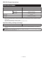 2
2
-
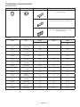 3
3
-
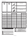 4
4
-
 5
5
-
 6
6
-
 7
7
-
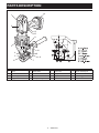 8
8
-
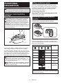 9
9
-
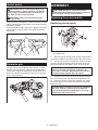 10
10
-
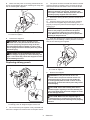 11
11
-
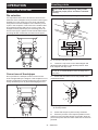 12
12
-
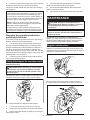 13
13
-
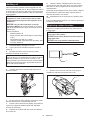 14
14
-
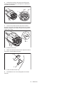 15
15
-
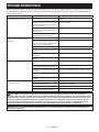 16
16
-
 17
17
-
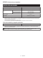 18
18
-
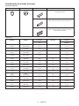 19
19
-
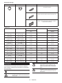 20
20
-
 21
21
-
 22
22
-
 23
23
-
 24
24
-
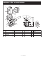 25
25
-
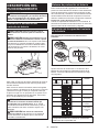 26
26
-
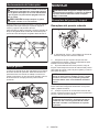 27
27
-
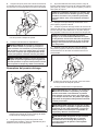 28
28
-
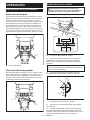 29
29
-
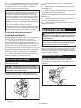 30
30
-
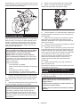 31
31
-
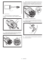 32
32
-
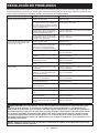 33
33
-
 34
34
-
 35
35
-
 36
36


Makita XPP01 Manual de usuario
- Categoría
- Herramientas eléctricas
- Tipo
- Manual de usuario
en otros idiomas
- English: Makita XPP01 User manual