
Installing the timer on the LOAD Side
1. Using the Load Side of Figure 3 as a visual reference, remove the LOAD
Side 3-way switch and the four wires, labeling the wire removed from the
common terminal as LOAD (4) and the wires from the HOT terminals (H)
as Traveler-1 (5) and Traveler-2 (7).
2. Using the Timer On LOAD Side of Figure 4 as a visual reference for the
remaining steps, connect the LOAD wire (4) to the LOAD terminal of the
timer.
3. Connect the Traveler-2 wire (7) to LINE terminal of the timer.
4. Connect the Traveler-1 wire (5) to the TRAVELER terminal of the timer.
5. Connect the white Neutral wire (2) from the switch box to the NEUTRAL
terminal of the timer. More neutral wires may be bundled in the back of
the switch box; there may be several neutral wires bound together with a
wire nut. Add the Neutral wire to the other neutral wires bound together,
ensuring the wire nut is tight. If needed use included jumper.
6. Connect the green Ground wire (3) in the switch box to the GROUND
terminal of the timer.
7. Carefully tuck the wires into the switch box, leaving room for the timer.
8. Use the supplied screws to install the timer, being careful not to crush or
pinch the wires.
9. Restore power at the circuit breaker or fuse box.
10. Verify that the LOAD turns ON/OFF when you manually turn the timer ON
and OFF. Perform this test with the remote switch in both positions. You
should hear the timer relay click ON/OFF. If you hear the relay click but the
LOAD does not turn ON/OFF properly, check your wiring.
11. If the load does not operate properly, disconnect the power at the circuit
breaker or fuse box. Then swap the Traveler-2 (Line) wire (7) and Traveler-1
wire (5) on the timer.
Timer on the LINE side 3-way installation instructions
NOTE: If you are unsure or unclear about this installation or if the wires in
your box do not match the manual (not all switch boxes have neutral wires),
contact a qualified, licensed electrician.
Preparing the switch on the LOAD side
1. Disconnect the power from the circuit by turning o the circuit breaker or
removing the fuse from the fuse box.
2. Using the Switch On LOAD Side of Figure 5 as a visual reference, label
and remove the LOAD wire (4) from the common terminal (C) and the
Traveler-2 wire (7) from the HOT terminal (H).
3. Using Figure 6 as a visual reference, connect the jumper wire (6)
(supplied), the LOAD wire (4) from the common terminal (C), and the
Traveler-2 wire (7) together. You should have three wires connected with
one wire nut. If needed use the included jumper.
4. Connect the other end of the jumper wire (6) back to the common
terminal (C) on the switch. Consider recording the marking/color coding
of the Traveler-1 (5) and Traveler-2 (7) wires so you can tell them apart for
later use.
5. Carefully tuck the wires into the switch box leaving room for the timer.
6. Install the switch back into the box.
Installing the timer on the LINE side
1. Using the LINE Side of Figure 5 as a visual reference, remove the LINE
Side 3-way switch and the four wires, labeling the wire removed from the
common terminal (C) as LINE (1) and the wires from the HOT terminals (H)
as Traveler-1 (5) and Traveler-2 (7).
2. Using the Timer on LINE Side of Figure 6 as a visual reference for the
remaining steps, connect the LINE wire (1) to the LINE terminal of the
timer.
3. Connect the white Neutral wire (2) to the NEUTRAL terminal of the timer.
More neutral wires may be bundled together in the back of the switch box;
there may be several neutral wires bound together with a wire nut. Add the
Neutral wire to the other neutral wires bound together, ensuring the wire
nut is tight.
4. Connect the Traveler-1 wire (5) to the TRAVELER terminal of the timer and
the Traveler-2 wire (7) to the LOAD terminal of the timer.
5. Connect the green Ground wire (3) to the GROUND terminal of the timer.
6. Carefully tuck the wires into the switch box, leaving room for the timer.
7. Use the supplied screws to install the timer, being careful not to crush or
pinch the wires.
8. Restore power at the circuit breaker or fuse box.
9. Verify that the LOAD turns ON/OFF when you manually turn the timer ON
and OFF. Perform this test with the remote switch in both positions. You
should hear the timer relay click ON/OFF. If you hear the relay click
but the LOAD does not turn ON/OFF properly, check your wiring.
10. If the load does not operate properly, disconnect the power at the circuit
breaker or fuse box. Then swap the Traveler-2 (LOAD) wire (7) and
Traveler-1 wire (5) at the timer or the toggle switch.
TRAVELER
LOADLINE
NEUTRAL
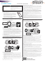
Typical Wiring Diagram for a 3-way installation
with timer on line side
Figure 6 - Connecting the timer wires for a 3-way
installation - timer on line side
1 = Line
2 = Neutral
3 = Ground
4 = Load
5 = Traveler-1
6 = Jumper
*7 = Traveler-2
C = Common
terminal
2
7
5
6
3
Ground
SWITCH ON LOAD SIDE
4
Load
C
Figure 5 - Typical wiring
schematic for 3-way installation
5
1
7
Hot Side
Line
LINE SIDE LOAD SIDE
C
H H
5
4
7
C
H H
Load
In a typical 3-way application there are two 3-way switches. The switch on the
“HOT” side has the common terminal tied to 120VAC. The switch on the “LOAD”
side has the common terminal tied to the load that the switches turn off and on.
Line
Neutral
Traveler-2 (Load)
Ground
Traveler-1
5
3
7
1
2
TIMER ON LINE SIDE
3
3
Ground
*Traveler-2 (7) carries Load
to the timer
H H
Change the door
This device includes a light almond door. To switch the
doors, proceed as follows:
1. Before installing the wall plate, or installing the timer,
open the timer door to be removed. Find the left
and right spot where the door snaps into the timer
hinges. Choose either the left or right side and pull
o the door from the timer. Once one side is pulled
o the other side will pull o easily.
2. Find the light almond door. Align the bottom of the
door with the hinges on the bottom of the timer.
Push in one of the sides of the door into the timer
hinge, it will snap into place. Snap in the second side
of the door to the timer. See Figure 1
Single-pole Installation
NOTE: If you are unsure or unclear about this installation or if the wires in
your box do not match the manual (not all switch boxes have neutral wires),
contact a qualified, licensed electrician.
Installation instructions (single-pole)
1. Turn OFF the main power at the circuit breaker or fuse box.
2. Remove the existing switch.
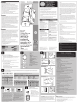
3. Connect the timer to the wall box wires as shown in Figure 2.
a) Connect the hot/live LINE wire to the LINE terminal of the timer.
b) Connect the hot/live LOAD wire to the LOAD terminal of the timer.
c) Connect the Ground wire to the GROUND terminal of the timer.
d) Connect the Neutral wire to the NEUTRAL terminal of the timer. Often
the Neutral wire can be found in the back of the wire box connected
with a wire nut. There may be several neutral wires bound together. Add
the timer Neutral wire to the other neutral wires, bound together making
sure the wire nut is tight. If needed use the included jumper.
4. Ensure that all terminals are tightened to between 8.85 and 12.39 lbf-in.,
and tuck the wires into the wall box, leaving room for the timer.
5. Use the screws to mount the timer to the wall box, being careful not to
crush any wires.
6. Reinstall your wallplate.
7. Turn the main power on at the circuit breaker.
8. If the timer does not turn on, disconnect the power at the circuit breaker
or fuse box. Swap the LINE and LOAD wires on the timer. Remount the
timer and wallplate, then restore power at the fuse box or circuit breaker.
Timer on LOAD side 3-way installation instructions
NOTE: If you are unsure or unclear about this installation or if the wires in
your box do not match the manual (not all switch boxes have neutral wires),
contact a qualified, licensed electrician.
Preparing the switch on the LINE Side
1. Disconnect the power from the circuit by turning o the circuit breaker
or removing the fuse from the fuse box.
2. Using the LINE Side of Figure 3 as a visual reference, label and remove
the LINE wire (1) from the common terminal (C) and the Traveler-2 wire
(7) from the HOT terminal (H).
3. Using Figure 4 as a visual reference, connect the jumper wire (6)
(supplied), the LINE wire (1) from the common terminal (C), and the
Traveler-2 wire (7) together. You should have three wires connected with
one wire nut.
4. Connect the other end of the jumper wire (6) back to the common
terminal (C) on the switch. Consider recording the marking/color coding
of the Traveler-1 (5) and Traveler-2 (7) wires so you can tell them apart
for later use.
5. Carefully tuck the wires into the box, leaving room for the switch.
6. Install the switch back into the box.
TRAVELER
LOADLINE
NEUTRAL
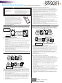
Figure 3 - Typical wiring
schematic for 3-way installation
2
7
5
6
1
3
Ground
C
Typical Wiring Diagram for 3-way installation
with timer on load side
Load
Line
5
1
7
3
3
Hot Side
Line
Ground
LINE SIDE
SWITCH ON LINE SIDE
LOAD SIDE
TIMER ON LOAD SIDE
C
H H
5
4
7
C
H H
Figure 4 - Connecting the timer wires for a
3-way installation - timer on load side
Load
1 = Line
2 = Neutral
3 = Ground
4 = Load
5 = Traveler-1
6 = Jumper
*7 = Traveler-2
C = Common
terminal
In a typical 3-way application there are two 3-way switches. The switch on the
“HOT” side has the common terminal tied to 120VAC. The switch on the “LOAD”
side has the common terminal tied to the load that the switches turn on and off.
Load
Neutral
Traveler-2 (Line)
Ground
Traveler-1
5
3
7
4
2
*Traveler-2 (7) carries Line to the timer
H H
TIMER
WALL BOX
Line
TRAVELER
LOADLINE
NEUTRAL
Included Neutral Jumper
Load
Ground
Figure 2 - Connecting the timer wires for single-pole installation
5/8” (1.6cm)
Wire Strip Length
WIRE
Step-by-Step
Instructional Video
RISK OF ELECTRIC SHOCK
• SHUT OFF POWER AT FUSE BOX
OR CIRCUIT BREAKER BEFORE
INSTALLATION
• DO NOT USE IN WET LOCATIONS
• USE INDOORS ONLY
RISK OF FIRE
•DO NOT USE TO CONTROL APPLIANCES THAT CONTAIN
HEATING ELEMENTS (COOKING APPLIANCES, HEATERS,
IRONS, ETC.)
• DO NOT EXCEED ELECTRICAL RATINGS
• DO NOT USE TO CONTROL RECEPTACLES
• USE COPPER WIRE ONLY WITH THIS DEVICE
• TIGHTEN ALL CONNECTIONS TO 1-1.4 N-m (8.85 TO 12.39
LBF-IN.)
• FOR SUPPLY CONNECTIONS, USE 14 AWG OR LARGER
WIRE RATED AT LEAST 75°C.
• FOR GROUNDING LEAD, USE 12 AWG OR LARGER WIRE
RATED AT LEAST 75°C.
In-Wall Digital
SunSmart™
In-Wall Timer
Line - Black
Load - Black
Neutral - White
Ground - Green
or Bare
Installation Instructions
WARNING
33861 Installation Instructions v1 12/18/17
Figure 1

Instalación del temporizador en el lado LOAD (carga)
1. Usando el lado LOAD (carga) de la Figura3 como referencia visual, quite el
interruptor de 3vías del lado LOAD (carga) y los cuatro cables. Etiquete el
cable que retiró del terminal común como LOAD (carga)(4) y cables de los
terminales vivos(H) como Terminal de retorno1(5) y Terminal de retorno2(7).
2. Usando el temporizador en el lado LOAD (carga) de la Figura4 como
referencia visual para los pasos restantes, conecte el cable LOAD (carga)(4) al
terminal LOAD (carga) del temporizador.
3. Conecte el cable de retorno2(7) al terminal LINE (línea) del temporizador.
4. Conecte el cable de retorno1(5) al terminal TRAVELER (retorno) del
temporizador.
5. Conecte el cable neutro blanco(2) de la caja de interruptores al terminal
NEUTRAL (neutro) del temporizador. Puede haber más cables neutros
amarrados en la parte trasera de la caja de interruptores con un empalme
de cable. Incluya el cable neutro a los otros cables neutros amarrados,
asegurándose de que el empalme de cable esté ajustado. De ser necesario, use
el cable del puente incluido.
6. Conecte el cable de tierra verde(3) de la caja de interruptores al terminal
GROUND (tierra) del temporizador.
7. Con cuidado, introduzca los cables en la caja de interruptores, dejando espacio
para el temporizador.
8. Utilice los tornillos provistos para instalar el temporizador, teniendo cuidado de
no apretar o pellizcar los cables.
9. Restablezca el suministro eléctrico en el disyuntor o panel de fusibles.
10. Verifique que la carga se conecte y desconecte al encender y apagar
manualmente el temporizador. Realice esta prueba con el interruptor remoto
en ambas posiciones. Debe escuchar un “clic” cuando el relé del temporizador
se enciende y apaga. Si escucha el “clic” del relé, pero la carga no se enciende
ni apaga correctamente, revise el cableado.
11. Si la carga no funciona correctamente, desconecte el suministro eléctrico en el
disyuntor o panel de fusibles. Luego, intercambie el cable de retorno2 (LINE,
línea)(7) y el cable de retorno1(5) en el temporizador.
Instrucciones de instalación de 3vías con el temporizador
en el lado LINE (línea)
NOTA: Si no está seguro o duda acerca de esta instalación, o si los cables de la
caja que usará no coinciden con el manual (no todas las cajas de interruptores
tienen cables neutros), comuníquese con un electricista calificado con licencia.
Preparación del interruptor en el lado LOAD (carga)
1. Apague el disyuntor o retire el fusible del panel de fusibles para desconectar el
suministro eléctrico del circuito.
2. Usando el interruptor en el lado LOAD (carga) de la Figura5 como referencia
visual, etiquete y quite el cable LOAD (carga)(4) del terminal común(C) y el
cable de retorno2(7) del terminal vivo(H).
3. Usando la Figura6 como referencia visual, conecte juntos el cable del
puente(6) (suministrado), el cable LOAD (carga)(4) del terminal común(C) y
el cable de retorno2(7). Debe tener tres cables conectados con un empalme
de cable. De ser necesario, use el cable del puente incluido.
4. Vuelva a conectar el otro extremo del cable del puente(6) en el terminal
común(C) del interruptor. Considere tomar nota de la codificación de
color/marcado de los cables de retorno1(5) y2(7) para poder distinguirlos
posteriormente.
5. Con cuidado, introduzca los cables en la caja de interruptores, dejando espacio
para el temporizador.
6. Vuelva a colocar el interruptor en la caja.
Instalación del temporizador en el lado LINE (línea)
1. Usando el lado LINE (línea) de la Figura5 como referencia visual, quite el
interruptor de 3vías del lado LINE (línea) y los cuatro cables. Etiquete el cable
que retiró del terminal común(C) como LINE (línea)(1) y los cables de los
terminales vivos(H) como Terminal de retorno1(5) y Terminal de retorno2(7).
2. Usando el temporizador en el lado LINE (línea) de la Figura6 como referencia
visual para los pasos restantes, conecte el cable LINE (línea)(1) al terminal LINE
(línea) del temporizador.
3. Conecte el cable neutro blanco(2) al terminal NEUTRAL (neutro) del
temporizador. Puede haber más cables neutros amarrados en la parte trasera
de la caja de interruptores con un empalme de cable. Incluya el cable neutro
a los otros cables neutros amarrados, asegurándose de que el empalme de
cable esté ajustado.
4. Conecte el cable de retorno1(5) al terminal TRAVELER (retorno) del
temporizador
y el cable de retorno2(7) al terminal LOAD (carga) del temporizador.
5. Conecte el cable de tierra verde(3) al terminal GROUND (tierra) del
temporizador.
6. Con cuidado, introduzca los cables en la caja de interruptores, dejando espacio
para el temporizador.
7. Utilice los tornillos provistos para instalar el temporizador, teniendo cuidado de
no apretar o pellizcar los cables.
8. Restablezca el suministro eléctrico en el disyuntor o panel de fusibles.
9. Verifique que la carga se conecte y desconecte al encender y apagar
manualmente el temporizador. Realice esta prueba con el interruptor remoto
en ambas posiciones. Debe escuchar un “clic” cuando el relé del temporizador
se enciende y apaga. Si escucha el “clic” del relé, pero la carga no se enciende
ni apaga correctamente, revise el cableado.
10. Si la carga no funciona correctamente, desconecte el suministro eléctrico
en el disyuntor o panel de fusibles. Luego, intercambie el cable de retorno2
(LOAD, carga)(7) y el cable de retorno1(5) en el temporizador o interruptor
basculante.
TRAVELER
LOADLINE
NEUTRAL
Diagrama de cableado típico para una instalación
de 3 vías con el temporizador en el lado LINE (línea)
Figura 6: Conexión de los cables del temporizador para una
instalación de 3 vías con el temporizador en el lado LINE (línea)
2
7
5
6
3
INTERRUPTOR EN EL LADO LOAD (carga)
4
Carga
C
Figura 5: Esquema de cableado
típico para una instalación de 3 vías
5
1
7
C
H H
5
4
7
C
H H
En una aplicación de 3 vías, existen dos interruptores de 3 vías. El interruptor del lado con
corriente (HOT) tiene el terminal común conectado a 120 V CA. El interruptor del lado “LOAD”
(carga) tiene el terminal común conectado a la carga que los interruptores desconectan y conectan.
5
3
7
1
2
TEMPORIZADOR EN EL LADO LINE (línea)
3
3
H
H
1 = Línea
2 = Neutral
3 = Conexión
4 = Carga
5 = Retorno 1
6 =
Cable del puente
*7 = Retorno 2
C = terminal
común
a tierra
Lado con corriente
Línea
Conexión
a tierra
LADO LINE (línea)
LADO LOAD (carga)
Carga
Carga
Neutral
Retorno 2 (
LOAD, carga
)
Conexión
a tierra
Retorno 1
Conexión
a tierra
Cambiar la tapa
Este dispositivo incluye una tapa color almendra claro. Para
cambiar las tapas, haga lo siguiente:
1. Antes de instalar la placa de pared o de instalar el
temporizador, abra la tapa del temporizador que se
debe retirar. Encuentre el punto a la izquierda y a la
derecha en donde la tapa encaja en las bisagras del
temporizador. Elija el lateral izquierdo o derecho y retire
la tapa del temporizador. Una vez retirado un lateral, el
otro saldrá fácilmente.
2. Busque la tapa color almendra claro. Alinee la parte
inferior de la tapa con las bisagras de la parte inferior
del temporizador. Presione uno de los laterales de la
tapa en la bisagra del temporizador, encajará en su
lugar. Inserte el segundo lateral de la tapa en el
temporizador. Ver Figura 1.
Instalación monofásica
NOTA: Si no está seguro o duda acerca de esta instalación, o si los cables de la
caja que usará no coinciden con el manual (no todas las cajas de interruptores
tienen cables neutros), comuníquese con un electricista calificado con licencia.
Instrucciones de instalación (monofásica)
1. Interrumpa la corriente principal al disyuntor o panel de fusibles.
2. Retire el interruptor existente.
3. Conecte el temporizador a los cables de la caja de embutir, como se muestra en
la Figura2.
a) Conecte el cable vivo/con corriente LINE (línea) al terminal LINE (línea) del
temporizador.
b) Conecte el cable vivo/con corriente LOAD (carga) al terminal LOAD (carga)
del temporizador.
c) Conecte el cable GROUND (tierra) al terminal GROUND (tierra) del
temporizador.
d) Conecte el cable NEUTRAL (neutro) al terminal NEUTRAL (neutro) del
temporizador. Muchas veces, el cable neutro se puede encontrar en la parte
trasera de la caja de embutir conectado con un empalme de cable. Puede haber
varios cables neutros amarrados. Incluya el cable neutro del temporizador a los
otros cables neutros amarrados, asegurándose de que el empalme de cable esté
ajustado. De ser necesario, use el cable del puente incluido.
4. Asegúrese de que todos los terminales estén ajustados en una configuración de
entre8,85 y 12,39lbf-in e introduzca los cables en la caja de embutir, dejando
espacio para el temporizador.
5. Use los tornillos para instalar el temporizador en la caja de embutir, teniendo
cuidado de no apretar los cables.
6. Vuelva a instalar la placa de pared.
7. Restablezca la corriente principal en el disyuntor.
8. Si el temporizador no enciende, desconecte el suministro eléctrico en el
disyuntor o panel de fusibles. Intercambie los cables LINE (línea) y LOAD (carga)
en el temporizador. Vuelva a montar el temporizador y la placa de pared; luego,
restablezca el suministro eléctrico en el disyuntor o panel de fusibles.
Instrucciones de instalación de 3vías con el temporizador
en el lado LOAD (carga)
NOTA: Si no está seguro o duda acerca de esta instalación, o si los cables de la
caja que usará no coinciden con el manual (no todas las cajas de interruptores
tienen cables neutros), comuníquese con un electricista calificado con licencia.
Preparación del interruptor en el lado LINE (línea)
1. Apague el disyuntor o retire el fusible del panel de fusibles para desconectar el
suministro eléctrico del circuito.
2. Usando el lado LINE (línea) de la Figura3 como referencia visual, etiquete y
quite el cable LINE (línea)(1) del terminal común(C) y el cable de retorno2(7)
del terminal vivo(H).
3. Usando la Figura4 como referencia visual, conecte juntos el cable del puente(6)
(suministrado), el cable LINE (línea)(1) del terminal común(C) y el cable de
retorno2(7). Debe tener tres cables conectados con un empalme de cable.
4. Vuelva a conectar el otro extremo del cable del puente(6) en el terminal
común(C) del interruptor. Considere tomar nota de la codificación de color/
marcado de los cables de retorno1(5) y2(7) para poder distinguirlos
posteriormente.
5. Con cuidado, introduzca los cables en la caja de embutir, dejando espacio
para el interruptor.
6. Vuelva a colocar el interruptor en la caja.
TRAVELER
LOADLINE
NEUTRAL
Figura 3: Esquema de cableado
típico para una instalación de 3 vías
2
7
5
6
1
3
C
Diagrama de cableado típico para una instalación
de 3 vías con el temporizador en el lado LOAD (carga)
Carga
Línea
5
1
7
3
3
Lado con corriente
Línea
Conexión
a tierra
LADO LINE (línea)
INTERRUPTOR EN EL LADO LINE (línea)
LADO LOAD (carga)
TEMPORIZADOR EN EL LADO LOAD (carga)
C
H H
5
4
7
C
H H
Figura 4: Conexión de los cables del temporizador para una
instalación de 3 vías con el temporizador en el lado LOAD (carga)
Carga
1 = Línea
2 = Neutral
3 = Conexión
4 = Carga
5 = Retorno 1
6 =
Cable del puente
*7 = Retorno 2
C = terminal
común
En una aplicación de 3 vías, existen dos interruptores de 3 vías. El interruptor del lado con
corriente (HOT) tiene el terminal común conectado a 120 V CA. El interruptor del lado “LOAD”
(carga) tiene el terminal común conectado a la carga que los interruptores conectan y desconectan.
Carga
Neutral
Retorno 2 (LINE, línea)
Conexión
a tierra
Retorno 1
5
3
7
4
2
*El retorno 2 (7) transporta la línea al temporizador.
H H
Conexión
a tierra
a tierra
TEMPORIZADOR
CAJA DE EMBUTIR
Línea
RETORNO
CARGALÍNEA
NEUTRAL
Cable del puente
neutro incluido
Carga
Conexión a tierra
Figura 2: Conexión de los cables del temporizador para una instalación monofásica
5/8” (1,6 cm)
Largo de pelado
del cable
CABLE
Video instructivo
paso a paso
RIESGO DE DESCARGA ELÉCTRICA
• INTERRUMPA EL SUMINISTRO ELÉCTRICO
DESDE EL PANEL DE FUSIBLES O EL
DISYUNTOR ANTES DE PROCEDER CON LA
INSTALACIÓN.
• NO UTILICE EL DISPOSITIVO EN
LUGARES HÚMEDOS.
• SOLO PARA USO EN INTERIORES.
ADVERTENCIA
RIESGO DE INCENDIO
NO UTILICE EL DISPOSITIVO PARA CONTROLAR APARATOS QUE
INCLUYAN RESISTENCIAS ELÉCTRICAS (APARATOS DE COCCIÓN,
CALEFACTORES, PLANCHAS,ETC.).
• NO SUPERE LOS VALORES NOMINALES ELÉCTRICOS.
• NO UTILICE EL DISPOSITIVO PARA CONTROLAR TOMACORRIENTES.
• USE SOLO ALAMBRE DE COBRE CON ESTE DISPOSITIVO.
• APRIETE TODAS LAS CONEXIONES A 1-1,4N-m (DE8,85 A 12,39LBF-IN).
• PARA LAS CONEXIONES DE SUMINISTRO, USE UN CABLE DE 14AWG O
UN CALIBRE SUPERIOR APTO, COMO MÍNIMO, PARA 75°C.
• PARA LA CONEXIÓN A TIERRA, USE UN CABLE DE 12AWG O UN
CALIBRE SUPERIOR APTO, COMO MÍNIMO, PARA 75°C.
Digital de pared
SunSmart™
Temporizador de pared
Instrucciones de instalación
Línea - Negro
Carga - Negro
Neutral - Blanco
Tierra - Verde
o Desnudo
Figura 1
-
 1
1
-
 2
2


myTouchSmart 33861-T1 Guía de instalación
- Tipo
- Guía de instalación
- Este manual también es adecuado para
en otros idiomas
Otros documentos
-
Jasco 15312 Manual de usuario
-
GE SunSmart 15312 Instrucciones de operación
-
GE 12723 Manual de usuario
-
-
wattstopper RH-250 Instrucciones de operación
-
-
 GE Enbrighten 26933 Manual de usuario
-
-
-
