Graff G-11553 Guía de instalación
- Categoría
- Artículos sanitarios
- Tipo
- Guía de instalación

1
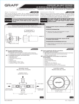
This faucet complies with NSF61/9, ASME/ANSI A112.18.1
and CSA B 125 Standards.
Este grifo se encuentra conforme con losestandares de NSF61/9,
de ASME/ANSI A112.18.1 y de CSA B 125. Installation Instructions Instrucciones de Instalación
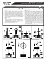
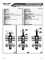
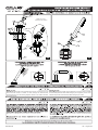
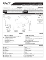
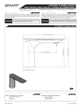
BATH FAUCET, 3-hole type
GRIFO PARA BAÑO, diseño de 3 agujeros
IOG 5206.70 Rev. 2 November 2019
Model
Modelo
MOD+ G-11552-***-L1**-T
O
2-1/4"
(57mm)
4-7/8"
(124mm)
7-7/8"
(200mm)
1-1/16"
(27mm)
1/4"
(6mm)
10-3/4"
(272mm)

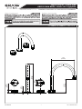
Model
Modelo
MOD+ G-11550-***-L1**-T
1
K1
K2
1
12
8
4.2
4.1
5
10
15
73.2
3.1
11
16
9
14
6
2
13
2
This faucet complies with NSF61/9, ASME/ANSI A112.18.1
and CSA B 125 Standards.
Este grifo se encuentra conforme con losestandares de NSF61/9,
de ASME/ANSI A112.18.1 y de CSA B 125. Installation Instructions Instrucciones de Instalación
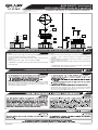
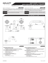
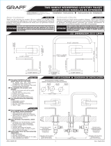
BATH FAUCET, 3-hole type
GRIFO PARA BAÑO, diseño de 3 agujeros
IOG 5206.70 Rev. 2 November 2019
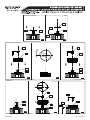
1-1/16"
(27mm)
1/4"
(6mm)
5-1/4"
(133mm)
1-7/8"
(47mm)
O
2-1/4"
(57mm)
7-1/2"
(190mm)
www.graff-designs.com

3
This faucet complies with NSF61/9, ASME/ANSI A112.18.1
and CSA B 125 Standards.
Este grifo se encuentra conforme con losestandares de NSF61/9,
de ASME/ANSI A112.18.1 y de CSA B 125. Installation Instructions Instrucciones de Instalación
BATH FAUCET, 3-hole type
GRIFO PARA BAÑO, diseño de 3 agujeros
IOG 5206.70 Rev. 2 November 2019
ENGLISH
~
ESPANOL
1
2
3.1
3.2
5
6
7
8
9
10
11
12
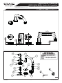
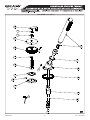
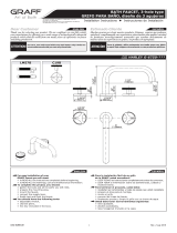
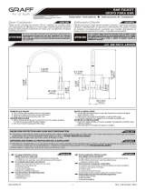
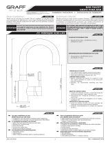
SPOUT BODY
BOLT
COVER OF THE SPOUT BASE
HANDLE BASE
BOLT
ELONGATION
AERATOR INSERT
CUERPO DEL CAÑO
PERNO
TAPA DE LA BASE DEL CAÑO
ZÓCALO
DE
LA
PALANCA
PERNO
EXTENSIÓN
AEREADOR
O-RING SEAL JUNTA TÓRICA
SLEEVE CASQUILLO
HANDLE INDICATOR INDICADOR DE PALANCA
RING OF THE SPOUT BASE ANILLO DE LA BASE DEL CAÑO
SCREW TORNILLO
3SPOUT BASE BASE DEL CAÑO
4.1
4.2
HANDLE BODY CUERPO DE LA PALANCA
HANDLE COVER TAPA DE LA PALANCA
4HANDLE PALANCA
13
14
O-RING SEAL JUNTA TÓRICA
BODY OF AERATOR CUERPO DEL AEREADOR
15 SLIDE WASHER ARANDELA DESLIZANTE
16 BOLT PERNO
K1
K2 SPECIAL KEY FOR THE AERATOR
2MM HEX KEY
LLAVE ESPECIAL PARA EL AEREADOR
LLAVE ALLEN 2MM
3
2
3
2
3
2

4
This faucet complies with NSF61/9, ASME/ANSI A112.18.1
and CSA B 125 Standards.
Este grifo se encuentra conforme con losestandares de NSF61/9,
de ASME/ANSI A112.18.1 y de CSA B 125. Installation Instructions Instrucciones de Instalación
BATH FAUCET, 3-hole type
GRIFO PARA BAÑO, diseño de 3 agujeros
IOG 5206.70 Rev. 2 November 2019
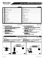
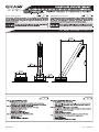
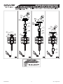
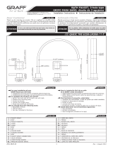
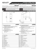
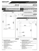
Change a standard valve spindle to the valve spindle (10) (fig.
3.1-3.2).
Set the handle base (7) on the installation surface. Place the base
in the correct position in relation to the collar and secure with a
setting screw (16) using the provided hex key (K1) - figs. 3.3-3.4.
Make sure the valve is in the closed position by turning the valve
spindle to the right (hot water valve) until you feel strong resistan-
ce. For the cold water valve, turn the valve spindle to the left.
If satisfactory alignment of the lever in relation to the bath edge is
impossible (a clear shift from the required position is required – as
in figure (fig. 3.6), remove the lever from the spindle (10), remove
the screw (11) and change the position of the valve spindle (10)
by a single tooth on the splined valve head and refit the bolt in
(11) (fig. 3.7-3.8).
Attach the lever (4) to the spindle (10) and check if the position is
correct.
-
-
Repeat these steps for the second lever (4).
Reemplazar una extensión estandar para la valvula de extensión
(10) ( fig. 3.1-3.2).
En la superficie de montaje coloque la cuerpo de la palanca (7).
Posicione la base en relación a la brida y asegúrela con el tornillo
de fijación (16) usando la llave allén adjunta (K1) - figs.3.3-3.4.
Asegúrese de que la válvula se encuentra en la posición “válvula
cerrada”, para ello, gire el vástago de la válvula a la derecha
(válvula para el agua caliente) hasta el momento de sentir
resistencia. Para el agua fría, gire el vástago de la válvula a la
izquierda.
Si no es posible lograr una alineación satisfactoria de la palanca en
relación con el borde del baño (se requiere un cambio claro desde
la posición requerida, como en la figura (fig. 3.6) quite la palanca
del vástago (10), quite el tornillo (11) y cambie la posición del
vástago de la válvula (10) en un sólo diente de la cabeza de la
válvula dentada y vuelva a ajustar el perno en (11) (fig.3.7-3.8).
Conecte la palanca (4) al vástago (10) y revise si la posición es
correcta.
-
-
Repita estos pasos para la segunda palanca (4).
1.
2.
3.
4.
5.
1.
2.
3.
4.
5.
If the lever (4) position is correct, fit the screw (5) using the key
(K1) (fig 3.10).
If the lever (4) position is still incorrect – move the valve spindle
(10) by one more tooth on the splined head and check again if
the lever (4) position is now correct (fig. 3.7-3.10).
Si la posición de la palanca (4) es correcta, ajuste el tornillo (5)
con la llave (K1) fig.3.10.
Si la posición de la palanca (4) aún es incorrecta - mueva el
vástago de la válvula (10) en un diente más de la cabeza denta-
da y revise nuevamente si la posición de la palanca (4) es
correcta (figs. 3.7-3.10).
LEVER INSTALLATION INSTALACIÓN DE LA PALANCA
See fig. 3.1-3.10 Ver las figs. 3.1-3.10
B
C
10
11
710
K1
16
3.1 3.2 3.3 3.4
10
4
7
DELTA
3.5 3.6 3.7
12
10
15
10
4
7
12

5
This faucet complies with NSF61/9, ASME/ANSI A112.18.1
and CSA B 125 Standards.
Este grifo se encuentra conforme con losestandares de NSF61/9,
de ASME/ANSI A112.18.1 y de CSA B 125. Installation Instructions Instrucciones de Instalación
BATH FAUCET, 3-hole type
GRIFO PARA BAÑO, diseño de 3 agujeros
IOG 5206.70 Rev. 2 November 2019
~
ESPANOL
ENGLISH
4
OPERATION DESCRIPTION
DESCRIPCIÓN DEL FUNCIONAMIENTO
It is recommended that every 3-6 months (depending on water
quality) you remove the aerator (item 6 , fig. 1) from the faucet
spout (1) in order to remove any impurities. For this purpose, use
the special key (K2) (supplied).
1.
2.
Una vez a 3-6 meses (dependiendo de la calidad del agua) se
recomienda quitar el difusor (pos. 6 dis. 1) del caño de la batería
(1) con el fin de limpiarlo de todo tipo de ensuciamiento. Para eso
use una llave especial (K2) anexa al juego.
1.
2.
~
ESPANOL
See figs. 1 Ver. fig. 1
ENGLISH
3
AFTER INSTALLATION BEFORE USE
DESPUES DE LA INSTALACIÓN Y ANTES DEL USO
Remove aerator insert (6) (use the special key (K2) supllied) and
turn faucet handle to the full on mixed position.
Turn on hot and cold water supply valves and flush water lines for 15
seconds .
Replace aerator insert (6) . Use the special key (K2)..
IMPORTANT: This flushes away any debris that could cause damage
to internal parts.
1.
2.
3.
Retire el inserto del aereador (6) (use una llave especial
(K2)) anexa
al juego) y gire el mango del grifo a la posición de mezclado
completo.
Abra las válvulas de suministro de agua fría y caliente y enjuague las
lineas de agua por 15 seg. .
Coloque el inserto del aereador (6) . Ajuste solo con la llave especial
(K2)..
IMPORTANTE: Esto limpia los residuos que podrían causar daño a
las piezas internas con un chorro de agua.
1.
2.
3.
1)
1)
1)
1)
5
3.8 3.9 3.10
10
11
10
4
7
12
K1
5
12
4

Model
Modelo
MOD+ G-11555-***-L1**-T
1
IOG 5207.80 Rev. 1 August 2019
2-1/4"
57mm
O
2-1/4"
57mm
O
8-1/4"
210mm
1"
25mm
O
4-1/2"
115mm

G-11555-***-L1**
2
IOG 5207.80 Rev. 1 August 2019
6
9
18
4.2
15
1
4.1
11
8
12
2
5
13
3
16
17
14
7
10
K1

3
IOG 5207.80 Rev. 1 August 2019
PERNO
TORNILLO
SCREW
14
15
18
17
16
ELONGATION EXTENSIÓN
14
15
18
17
16
HANDLE INDICATOR INDICADOR DE PALANCA
O-RING SEAL JUNTA TÓRICA
SLEEVE CASQUILLO
HOLDER RING ANILLO SOPORTE
4.2
4.1
4.2
4.1
HANDLE COVER TAPA DE LA PALANCA
HANDLE BODY CUERPO DE LA PALANCA
B
C
14
13

4
IOG 5207.80 Rev. 1 August 2019
14
4
1
DELTA
2.6 2.7 2.8
15
14
4
1
15
114
K1
2
2.4 2.5
14
3
2.9 2.10 2.11
14
13
14
4
1
15
K1
5
15
4

5
IOG 5207.80
12
C
C
Rev. 1 August 2019
Change a standard valve spindle to the valve spindle (14) (fig.
2.2-2.3). Reemplazar una extensión estandar para la valvula de extensión
(14) ( fig. 2.2-2.3).
Set the handle base (1) on the installation surface. Place the base
in the correct position in relation to the collar and secure with a
setting screw (2) using the pr
o
vided hex key (K1) - figs. 2.4-2.5.
If satisfactory alignment of the lever in rela
t
ion to the bath edge is
impossible (a clear shift from the required position is required – as
in figure (fig. 2.7), remove the lever from the spindle (14), remove
the screw (13) and change the position of the valve spindle (14)
by a single tooth on the splined valve head and refit the bolt in
(13) (fig. 2.8-2.9).
Attach the lever (4) to the spindle (14) and check if the position is
correct.
-
-
Repeat these steps for the second lever (4).
En la superficie de montaje coloque la cuerpo de la palanca (1).
Posicione la base en relación a la brida y asegúrela con el tornillo
de fijación (2) usando la llave allén adjunta (K1) - figs. 2.4-2.5.
Si no es posible lograr una alineación satisfactoria de la palanca en
relación con el borde del baño (se requiere un cambio claro desde
la posición requerida, como en la figura (fig. 2.7) quite la palanca
del vástago (14), quite el tornillo (13) y cambie la posición del
vástago de la válvula (14) en un sólo diente de la cabeza de la
válvula dentada y vuelva a ajustar el perno en (13) (fig.2.8-2.9).
Conecte la palanca (4) al vástago (14) y revise si la posición es
correcta.
-
-
Repita estos pasos para la segunda palanca (4).
3.
4.
5.
6.
3.
4.
5.
6.
If the lever (4) position is correct, fit the screw (5) using the key
(K1) (fig 2.11).
If the lever (4) position is still incorrect – move the valve spindle
(14) by one more tooth on the splined head and check again if
the lever (4) position is now correct (fig. 2.8-2.11).
Si la posición de la palanca (4) es correcta, ajuste el tornillo (5)
con la llave (K1) fig.2.11.
Si la posición de la palanca (4) aún es incorrecta - mueva el
vástago de la válvula (14) en un diente más de la cabeza denta-
da y revise nuevamente si la posición de la palanca (4) es
correcta (figs. 2.8-2.11).
1.
2. 1.
2.
6
3.6
6
3.6
3.6 3.6
(R2)
(R2) (R2)
(R2)
Place the hand shower base
and holder ring
(32)
(pay attention to the holes in the ring and the
setting screw (10)
using the provided hex key
(K1)
holder), secure with a
Coloque la base de la ducha de mano
(9)
en la posición correcta sobre la superficie de instalación en relación
(R2) y el anillo de soporte (32) (preste atención a los
el soporte), asegure con un tornillo de ajuste
(10)
usando la llave hexagonal proporcionada.
(K1)
- Figuras 6,4.
con el cuello
orificios en el anillo y

6
IOG 5207.80 Rev. 1 August 2019
7
9
7R4
R5
8
R3
8
9
9
8
R3
7
7
R4
R4
R3
R1
R2
18
www.graff-designs.com

7
IOG 5207.80
When the lever is set as recommended in the manual: Turning the lever by
180° to the left results in outflow of water through the hand shower,
returning the lever to the starting setpoint results in the outflow of water
through the spout.
Para la posición de la manilla recomendada en el manual: Girar la manilla
en 180° a la izquierda causa la salida del agua por la regadera, volver con la
manilla a la posición inicial causa la salida del agua por el caño.
Rev. 1 August 2019
C
7
12
9
3.6
Match the holes
Empareje los orificios
9
7
10
K1
R3
8
K1
10
18
R5
4.1
3.5
-
 1
1
-
 2
2
-
 3
3
-
 4
4
-
 5
5
-
 6
6
-
 7
7
-
 8
8
-
 9
9
-
 10
10
-
 11
11
-
 12
12


Graff G-11553 Guía de instalación
- Categoría
- Artículos sanitarios
- Tipo
- Guía de instalación
En otros idiomas
- English: Graff G-11553 Installation guide
Documentos relacionados
-
 Graff G-11351-LM56B Guía de instalación
-
 Graff G-6751-C19B Guía de instalación
-
 Graff G-6251-LM39B Guía de instalación
-
 Graff G-6153-LM41B Guía de instalación
-
 Graff G-2311-LM40-SN Guía de instalación
-
 Graff G-5676-LM49D Guía de instalación
-
 Graff G-6104-LM41M Guía de instalación
-
 Graff Faucets G-6300-LM42-PC Guía de instalación
-
 Graff G-5230-LM3 Guía de instalación
-
 Graff G-4866 Guía de instalación