Peavey Tour 700 Instrucciones de operación
- Categoría
- Equipo de música suplementario
- Tipo
- Instrucciones de operación


2
Intended to alert the user to the presence of uninsulated “dangerous voltage” within the product’s
enclosure that may be of sufficient magnitude to constitute a risk of electric shock to persons.
Intended to alert the user of the presence of important operating and maintenance (servicing)
instructions in the literature accompanying the product.
CAUTION: Risk of electrical shock — DO NOT OPEN!
CAUTION: To reduce the risk of electric shock, do not remove cover. No user serviceable parts inside.
Refer servicing to qualified service personnel.
WARNING: To prevent electrical shock or fire hazard, this apparatus should not be exposed to rain or
moisture‚ and objects filled with liquids‚ such as vases‚ should not be placed on this apparatus. Before
using this apparatus‚ read the operating guide for further warnings.
Este símbolo tiene el propósito, de alertar al usuario de la presencia de “(voltaje) peligroso” sin
aislamiento dentro de la caja del producto y que puede tener una magnitud suficiente como para
constituir riesgo de descarga eléctrica.
Este símbolo tiene el propósito de alertar al usario de la presencia de instruccones importantes sobre la
operación y mantenimiento en la información que viene con el producto.
PRECAUCION: Riesgo de descarga eléctrica ¡NO ABRIR!
PRECAUCION: Para disminuír el riesgo de descarga eléctrica, no abra la cubierta. No hay piezas útiles
dentro. Deje todo mantenimiento en manos del personal técnico cualificado.
ADVERTENCIA: Para prevenir choque electrico o riesgo de incendios, este aparato no se debe exponer a
la lluvia o a la humedad. Los objetos llenos de liquidos, como los floreros, no se deben colocar encima
de este aparato. Antes de usar este aparato, lea la guia de funcionamiento para otras advertencias.
Ce symbole est utilisé dans ce manuel pour indiquer à l’utilisateur la présence d’une tension dangereuse
pouvant être d’amplitude suffisante pour constituer un risque de choc électrique.
Ce symbole est utilisé dans ce manuel pour indiquer à l’utilisateur qu’il ou qu’elle trouvera d’importantes
instructions concernant l’utilisation et l’entretien de l’appareil dans le paragraphe signalé.
ATTENTION: Risques de choc électrique — NE PAS OUVRIR!
ATTENTION: Afin de réduire le risque de choc électrique, ne pas enlever le couvercle. Il ne se trouve
à l’intérieur aucune pièce pouvant être reparée par l’utilisateur. Confiez I’entretien et la réparation de
l’appareil à un réparateur Peavey agréé.
AVIS: Dans le but de reduire les risques d’incendie ou de decharge electrique, cet appareil ne doit
pas etre expose a la pluie ou a l’humidite et aucun objet rempli de liquide, tel qu’un vase, ne doit
etre pose sur celui-ci. Avant d’utiliser de cet appareil, lisez attentivement le guide fonctionnant pour
avertissements supplémentaires.
Dieses Symbol soll den Anwender vor unisolierten gefährlichen Spannungen innerhalb des Gehäuses
warnen, die von Ausreichender Stärke sind, um einen elektrischen Schlag verursachen zu können.
Dieses Symbol soll den Benutzer auf wichtige Instruktionen in der Bedienungsanleitung aufmerksam
machen, die Handhabung und Wartung des Produkts betreffen.
VORSICHT: Risiko — Elektrischer Schlag! Nicht öffnen!
VORSICHT: Um das Risiko eines elektrischen Schlages zu vermeiden, nicht die Abdeckung enfernen.
Es befinden sich keine Teile darin, die vom Anwender repariert werden könnten. Reparaturen nur von
qualifiziertem Fachpersonal durchführen lassen.
WARNUNG: Um elektrischen Schlag oder Brandgefahr zu verhindern, sollte dieser Apparat nicht
Regen oder Feuchtigkeit ausgesetzt werden und Gegenstände mit Flüssigkeiten gefuellt, wie Vasen,
nicht auf diesen Apparat gesetzt werden. Bevor dieser Apparat verwendet wird, lesen Sie bitte den
Funktionsführer für weitere Warnungen.

3
IMPORTANT SAFETY INSTRUCTIONS
WARNING: When using electrical products, basic cautions should always be followed, including the following:
1. Read these instructions.
2. Keep these instructions.
3. Heed all warnings.
4. Follow all instructions.
5. Do not use this apparatus near water.
6. Clean only with a dry cloth.
7. Do not block any of the ventilation openings. Install in accordance with manufacturer’s instructions.
8. Do not install near any heat sources such as radiators, heat registers, stoves or other apparatus (including amplifiers)
that produce heat.
9. Do not defeat the safety purpose of the polarized or grounding-type plug. A polarized plug has two blades with one
wider than the other. A grounding type plug has two blades and a third grounding plug. The wide blade or third prong is
provided for your safety. If the provided plug does not fit into your outlet, consult an electrician for replacement of the
obsolete outlet.
10. Protect the power cord from being walked on or pinched, particularly at plugs, convenience receptacles, and the point
they exit from the apparatus.
11. Only use attachments/accessories provided by the manufacturer.
12. Use only with a cart, stand, tripod, bracket, or table specified by the manufacturer, or sold with the apparatus. When a
cart is used, use caution when moving the cart/apparatus combination to avoid injury from tip-over.
13. Unplug this apparatus during lightning storms or when unused for long periods of time.
14. Refer all servicing to qualified service personnel. Servicing is required when the apparatus has been damaged in
any way, such as when power-supply cord or plug is damaged, liquid has been spilled or objects have fallen into the
apparatus, the apparatus has been exposed to rain or moisture, does not operate normally, or has been dropped.
15. Never break off the ground pin. Write for our free booklet “Shock Hazard and Grounding.” Connect only to a power
supply of the type marked on the unit adjacent to the power supply cord.
16. If this product is to be mounted in an equipment rack, rear support should be provided.
17. Note for UK only: If the colors of the wires in the mains lead of this unit do not correspond with the terminals in your
plug‚ proceed as follows:
a) The wire that is colored green and yellow must be connected to the terminal that is marked by the letter E‚ the earth
symbol‚ colored green or colored green and yellow.
b) The wire that is colored blue must be connected to the terminal that is marked with the letter N or the color black.
c) The wire that is colored brown must be connected to the terminal that is marked with the letter L or the color red.
18. This electrical apparatus should not be exposed to dripping or splashing and care should be taken not to place objects
containing liquids, such as vases, upon the apparatus.
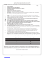
19. Exposure to extremely high noise levels may cause a permanent hearing loss. Individuals vary considerably in suscep-
tibility to noise-induced hearing loss, but nearly everyone will lose some hearing if exposed to sufficiently intense noise
for a sufficient time. The U.S. Government’s Occupational Safety and Health Administration (OSHA) has specified the
following permissible noise level exposures:
Duration Per Day In Hours Sound Level dBA, Slow Response
8 90
6 92
4 95
3 97
2 100
1 1⁄2 102
1 105
1⁄2 110
1⁄4 or less 115
According to OSHA, any exposure in excess of the above permissible limits could result in some hearing loss. Earplugs or protectors to
the ear canals or over the ears must be worn when operating this amplification system in order to prevent a permanent hearing loss, if
exposure is in excess of the limits as set forth above. To ensure against potentially dangerous exposure to high sound pressure levels, it is
recommended that all persons exposed to equipment capable of producing high sound pressure levels such as this amplification system be
protected by hearing protectors while this unit is in operation.
SAVE THESE INSTRUCTIONS!

4
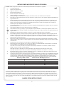
WICHTIGE SICHERHEITSHINWEISE
ACHTUNG: Beim Einsatz von Elektrogeräten müssen u.a. grundlegende Vorsichtsmaßnahmen befolgt werden:
1. Lesen Sie sich diese Anweisungen durch.
2. Bewahren Sie diese Anweisungen auf.
3. Beachten Sie alle Warnungen.
4. Befolgen Sie alle Anweisungen.
5. Setzen Sie dieses Gerät nicht in der Nähe von Wasser ein.
6. Reinigen Sie es nur mit einem trockenen Tuch.
7. Blockieren Sie keine der Lüftungsöffnungen. Führen Sie die Installation gemäß den Anweisungen des Herstellers durch.
8. Installieren Sie das Gerät nicht neben Wärmequellen wie Heizungen, Heizgeräten, Öfen oder anderen Geräten (auch Verstärkern),
die Wärme erzeugen.
9. Beeinträchtigen Sie nicht die Sicherheitswirkung des gepolten Steckers bzw. des Erdungssteckers. Ein gepolter Stecker weist
zwei Stifte auf, von denen einer breiter ist als der andere. Ein Erdungsstecker weist zwei Stifte und einen dritten Erdungsstift auf.
Der breite Stift bzw. der dritte Stift dient Ihrer Sicherheit. Sollte der beiliegende Stecker nicht in Ihre Steckdose passen, wenden
Sie sich bitte an einen Elektriker, um die ungeeignete Steckdose austauschen zu lassen.
10. Schützen Sie das Netzkabel, sodass niemand darauf tritt oder es geknickt wird, insbesondere an Steckern oder Buchsen und
ihren Austrittsstellen aus dem Gerät.
11. Verwenden Sie nur die vom Hersteller erhältlichen Zubehörgeräte oder Zubehörteile.
12. Verwenden Sie nur einen Wagen, Stativ, Dreifuß, Träger oder Tisch, der den Angaben des Herstellers entspricht oder zusammen
mit dem Gerät verkauft wurde. Wird ein Wagen verwendet, bewegen Sie den Wagen mit dem darauf befindlichen Gerät besonders
vorsichtig, damit er nicht umkippt und möglicherweise jemand verletzt wird.
13. Trennen Sie das Gerät während eines Gewitters oder während längerer Zeiträume, in denen es nicht benutzt wird, von der
Stromversorgung.
14. Lassen Sie sämtliche Wartungsarbeiten von qualifizierten Kundendiensttechnikern durchführen. Eine Wartung ist erforderlich,
wenn das Gerät in irgendeiner Art beschädigt wurde, etwa wenn das Netzkabel oder der Netzstecker beschädigt wurden,
Flüssigkeit oder Gegenstände in das Gerät gelangt sind, das Gerät Regen oder Feuchtigkeit ausgesetzt wurde, nicht normal
arbeitet oder heruntergefallen ist.
15. Der Erdungsstift darf nie entfernt werden. Auf Wunsch senden wir Ihnen gerne unsere kostenlose Broschüre „Shock Hazard and
Grounding“ (Gefahr durch elektrischen Schlag und Erdung) zu. Schließen Sie nur an die Stromversorgung der Art an, die am
Gerät neben dem Netzkabel angegeben ist.
16. Wenn dieses Produkt in ein Geräte-Rack eingebaut werden soll, muss eine Versorgung über die Rückseite eingerichtet werden.
17. Hinweis – Nur für Großbritannien: Sollte die Farbe der Drähte in der Netzleitung dieses Geräts nicht mit den Klemmen in Ihrem
Stecker übereinstimmen, gehen Sie folgendermaßen vor:
a) Der grün-gelbe Draht muss an die mit E (Symbol für Erde) markierte bzw. grüne oder grün-gelbe Klemme angeschlossen
werden.
b) Der blaue Draht muss an die mit N markierte bzw. schwarze Klemme angeschlossen werden.
c) Der braune Draht muss an die mit L markierte bzw. rote Klemme angeschlossen werden.
18. Dieses Gerät darf nicht ungeschützt Wassertropfen und Wasserspritzern ausgesetzt werden und es muss darauf geachtet
werden, dass keine mit Flüssigkeiten gefüllte Gegenstände, wie z. B. Blumenvasen, auf dem Gerät abgestellt werden.
19. Belastung durch extrem hohe Lärmpegel kann zu dauerhaftem Gehörverlust führen. Die Anfälligkeit für durch Lärm bedingten
Gehörverlust ist von Mensch zu Mensch verschieden, das Gehör wird jedoch bei jedem in gewissem Maße geschädigt, der über
einen bestimmten Zeitraum ausreichend starkem Lärm ausgesetzt ist. Die US-Arbeitsschutzbehörde (Occupational and Health
Administration, OSHA) hat die folgenden zulässigen Pegel für Lärmbelastung festgelegt:
Dauer pro Tag in Stunden Geräuschpegel dBA, langsame Reaktion
8 90
6 92
4 95
3 97
2 100
1
1
⁄
2
102
1 105
1
⁄
2
110
1
⁄
4
oder weniger 115
Laut OSHA kann jede Belastung über den obenstehenden zulässigen Grenzwerten zu einem gewissen Gehörverlust führen. Sollte
die Belastung die obenstehenden Grenzwerte übersteigen, müssen beim Betrieb dieses Verstärkungssystems Ohrenstopfen oder
Schutzvorrichtungen im Gehörgang oder über den Ohren getragen werden, um einen dauerhaften Gehörverlust zu verhindern. Um sich vor
einer möglicherweise gefährlichen Belastung durch hohe Schalldruckpegel zu schützen, wird allen Personen empfohlen, die mit Geräten
arbeiten, die wie dieses Verstärkungssystem hohe Schalldruckpegel erzeugen können, beim Betrieb dieses Geräts einen Gehörschutz zu tra-
gen.
BEWAHREN SIE DIESE SICHERHEITSHINWEISE AUF!

5
INSTRUCTIONS IMPORTANTES DE SECURITE
ATTENTION: L’utilisation de tout appareil électrique doit être soumise aux precautions d’usage incluant:
1. Lire ces instructions.
2. Gardez ce manuel pour de futures références.
3. Prétez attention aux messages de précautions de ce manuel.
4. Suivez ces instructions.
5. N’utilisez pas cette unité proche de plans d’eau.
6. N’utilisez qu’un tissu sec pour le nettoyage de votre unité.
7. N’obstruez pas les systèmes de refroidissement de votre unité et installez votre unité en fonction des instructions
de ce manuel.
8. Ne positionnez pas votre unité à proximité de toute source de chaleur.
9. Connectez toujours votre unité sur une alimentation munie de prise de terre utilisant le cordon d’alimentation
fourni.
10. Protégez les connecteurs de votre unité et positionnez les cablages pour éviter toutes déconnexions accidentelles.
11. N’utilisez que des fixations approuvées par le fabriquant.
12. Lors de l’utilsation sur pied ou pole de support, assurez dans le cas de déplacement de l’ensemble enceinte/
support de prévenir tout basculement intempestif de celui-ci.
13. Il est conseillé de déconnecter du secteur votre unité en cas d’orage ou de durée prolongée sans utilisation.
14. Seul un technicien agréé par le fabriquant est à même de réparer/contrôler votre unité. Celle-ci doit être contrôlée si
elle a subit des dommages de manipulation, d’utilisation ou de stockage (humidité,…).
15. Ne déconnectez jamais la prise de terre de votre unité.
16. Si votre unité est destinée a etre montée en rack, des supports arriere doivent etre utilises.
17. Note pour les Royaumes-Unis: Si les couleurs de connecteurs du cable d’alimentation ne correspond pas au guide
de la prise secteur, procédez comme suit:
a) Le connecteur vert et jaune doit être connectrer au terminal noté E, indiquant la prise de terre ou correspondant
aux couleurs verte ou verte et jaune du guide.
b) Le connecteur Bleu doit être connectrer au terminal noté N, correspondnat à la couleur noire du guide.
c) Le connecteur marron doit être connectrer au terminal noté L, correspondant à la couleur rouge du guide.
18. Cet équipement électrique ne doit en aucun cas être en contact avec un quelconque liquide et aucun objet
contenant un liquide, vase ou autre ne devrait être posé sur celui-ci.
19. Une exposition à de hauts niveaux sonores peut conduire à des dommages de l’écoute irréversibles. La suscep-
tibilité au bruit varie considérablement d’un individu à l’autre, mais une large majorité de la population expériencera
une perte de l’écoute après une exposition à une forte puissance sonore pour une durée prolongée. L’organisme de
la santé américaine (OSHA) a produit le guide ci-dessous en rapport à la perte occasionnée:
Durée par Jour (heures) Niveau sonore moyen (dBA)
8 90
6 92
4 95
3 97
2 100
1
1
⁄
2
102
1 105
1
⁄
2
110
1
⁄
4
ou inférieur 115
D’après les études menées par le OSHA, toute exposition au delà des limites décrites ce-dessus entrainera des pertes de l’écoute chez la
plupart des sujets. Le port de système de protection (casque, oreilette de filtrage,…) doit être observé lors de l’opération cette unité ou des
dommages irréversibles peuvent être occasionnés. Le port de ces systèmes doit être observé par toutes personnes susceptibles d’être expo-
sées à des conditions au delà des limites décrites ci-dessus.
GARDEZ CES INSTRUCTIONS!

6
INSTRUCCIONES IMPORTANTES PARA SU SEGURIDAD
CUIDADO: Cuando use productos electrónicos, debe tomar precauciones básicas, incluyendo las siguientes:
1. Lea estas instrucciones.
2. Guarde estas instrucciones.
3. Haga caso de todos los consejos.
4. Siga todas las instrucciones.
5. No usar este aparato cerca del agua.
6. Limpiar solamente con una tela seca.
7. No bloquear ninguna de las salidas de ventilación. Instalar de acuerdo a las instrucciones del fabricante.
8. No instalar cerca de ninguna fuente de calor como radiadores, estufas, hornos u otros aparatos (incluyendo amplificadores)
que produzcan calor.
9. No retire la patilla protectora del enchufe polarizado o de tipo “a Tierra”. Un enchufe polarizado tiene dos puntas, una de
ellas más ancha que la otra. Un enchufe de tipo “a Tierra” tiene dos puntas y una tercera “a Tierra”. La punta ancha (la
tercera ) se proporciona para su seguridad. Si el enchufe proporcionado no encaja en su enchufe de red, consulte a un
electricista para que reemplaze su enchufe obsoleto.
10. Proteja el cable de alimentación para que no sea pisado o pinchado, particularmente en los enchufes, huecos, y los puntos
que salen del aparato.
11. Usar solamente añadidos/accesorios proporcionados por el fabricante.
12. Usar solamente un carro, pie, trípode, o soporte especificado por el fabricante, o vendido junto al aparato. Cuando se use
un carro, tenga cuidado al mover el conjunto carro/aparato para evitar que se dañe en un vuelco. No suspenda esta caja de
ninguna manera.
13. Desenchufe este aparato durante tormentas o cuando no sea usado durante largos periodos de tiempo.
14. Para cualquier reparación, acuda a personal de servicio cualificado. Se requieren reparaciones cuando el aparato ha sido
dañado de alguna manera, como cuando el cable de alimentación o el enchufe se han dañado, algún líquido ha sido
derramado o algún objeto ha caído dentro del aparato, el aparato ha sido expuesto a la lluvia o la humedad, no funciona de
manera normal, o ha sufrido una caída.
15. Nunca retire la patilla de Tierra.Escríbanos para obtener nuestro folleto gratuito “Shock Hazard and Grounding” (“Peligro
de Electrocución y Toma a Tierra”). Conecte el aparato sólo a una fuente de alimentación del tipo marcado al lado del cable
de alimentación.
16. Si este producto va a ser enracado con más equipo, use algún tipo de apoyo trasero.
17. Nota para el Reino Unido solamente: Si los colores de los cables en el enchufe principal de esta unidad no corresponden
con los terminales en su enchufe‚ proceda de la siguiente manera:
a) El cable de color verde y azul debe ser conectado al terminal que está marcado con la letra E‚ el símbolo de Tierra
(earth)‚ coloreado en verde o en verde y amarillo.
b) El cable coloreado en azul debe ser conectado al terminal que está marcado con la letra N o el color negro.
c) El cable coloreado en marrón debe ser conectado al terminal que está marcado con la letra L o el color rojo.
18. Este aparato eléctrico no debe ser sometido a ningún tipo de goteo o salpicadura y se debe tener cuidado para no poner
objetos que contengan líquidos, como vasos, sobre el aparato.
19. La exposición a altos niveles de ruido puede causar una pérdida permanente en la audición. La susceptibilidad a la pérdida
de audición provocada por el ruido varía según la persona, pero casi todo el mundo perderá algo de audición si se expone
a un nivel de ruido suficientemante intenso durante un tiempo determinado. El Departamento para la Salud y para la
Seguridad del Gobierno de los Estados Unidos (OSHA) ha especificado las siguientes exposiciones al ruido permisibles:
Duración por Día en Horas Nivel de Sonido dBA, Respuesta Lenta
8 90
6 92
4 95
3 97
2 100
1
1
⁄
2
102
1 105
1
⁄
2
110
1
⁄
4
o menos 115
De acuerdo al OSHA, cualquier exposición que exceda los límites arriba indicados puede producir algún tipo de pérdida en la audición.
Protectores para los canales auditivos o tapones para los oídos deben ser usados cuando se opere con este sistema de sonido para preve-
nir una pérdida permanente en la audición, si la exposición excede los límites indicados más arriba. Para protegerse de una exposición a
altos niveles de sonido potencialmente peligrosa, se recomienda que todas las personas expuestas a equipamiento capaz de producir altos
niveles de presión sonora, tales como este sistema de amplificación, se encuentren protegidas por protectores auditivos mientras esta uni-
dad esté operando.
GUARDE ESTAS INSTRUCCIONES!

7
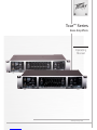
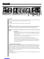
Tour™ Series 450/700
Bass Amplifiers
Congratulations on the purchase of your new Tour Bass amplier from Peavey®. The Tour series is a class leader in power.
The Tour series features class A/B power ampliers with patented SmartRail™ and DDT™ technologies. This technology gives
these amps massive dynamic power in a lightweight package, without introducing any switching distortion or delay. Each amp
features DC protection, an efcient parallel cooling system and a two-speed cooling fan. But that's not all. These amps contain
an analog octave divider which allows the user to synthesize a note one full octave below the note you are playing. Wrap all this
up with a constant Q, 9-band, graphic equalizer and the Peavey reputation for quality, and you couldn't ask for anything else.
Before you begin playing through your amplifier, it is very important to ensure that the product has the proper AC line voltage
supplied. You can find the proper voltage for your amp printed next to the IEC line (power) cord on the rear panel of the unit.
Each product feature is numbered. Refer to the front panel diagram in this manual to locate the particular features next to its
number.
Please read this guide carefully to ensure your personal safety as well as the safety of your amplifier.
FEATURES:
• Bypassable 9-band graphic equalizer with push-button bypass
• Patented SmartRail™ technology
• Patented DDT™ (Distortion Detection Technique) technology
• Analog Octave Divider with footswitchable bypass
• Buffered Effects Loop
• Speakon® combination 1/4" Speaker Jacks
• Two input jacks for active & passive basses
• Pre and Post Gain controls
• Bright and low-cut switches
• Low & High Shelving EQ
• Contour Control
ENGLISH
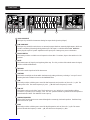
VENTILATION: For proper ventilation, allow 12" clearance from the nearest combustible surface.
Make sure that all vents are not blocked and air can flow freely throught the unit.

2 6
8
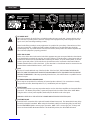
HIGH GAIN INPUT
This input is provided for instruments having low ouput levels (passive pickups).
LOW GAIN INPUT
This input is provided for active basses or external preamps that have extremely high outputs, which can
result in overdriving (distorting) the High Gain input. This input is -10dB from HIGH GAIN. WARNING:
Never plug the ouput of a power amplier into the input jacks. Damage may occur to both units.
BRIGHT SWITCH
This button provides a 10 dB boost to frequencies above 1KHz. To activate, depress the switch to its “IN”
position.
MUTE
This button mutes all signals passing through the amp. The “IN” position of the switch mutes the signal,
and the red LED will illuminate.
PRE GAIN
This knob controls input level of the instrument.
CONTOUR
This knob boosts highs and lows while simultaneously cutting mid tones producing a "scooped" sound.
Rotating the knob clockwise increases the CONTOUR effect.
LOW
This knob provides a shelving tone control for low frequencies and provides cut/boost of +/-15 dB. The
center point is at. The center frequency is 50 Hz. -3 dB shelf corner frequency is 100Hz.
LOW CUT
This button can be used to help "tame" the B-string on a 5 or 6 string bass, control speaker cabinet
resonance, or provide a more "vintage" tone. The "IN" position activates a gradual roll-off of frequencies
lower than 80Hz. NOTE: The LOW CUT circuit is pre-eq.
GRAPHIC EQUALIZER
These sliders provide precise tone control through the constant-Q, nine band equalizer. Each band may
be boosted or cut 15 dB.
HIGH
This knob provides a shelving tone control for high frequencies and cut/boost of +/-15dB. The center
point is at and the frequency is 8 KHz. -3dB; the shelf corner frequency is 5 KHz.
Front Panel
1
2
3
4
5
6
7
8
9
10
1 3 4 5 7 8 9 10

9
Front Panel
EQ BYPASS
This button removes the graphic equalizer from the audio chain. The “IN” position of the switch bypass-
es the EQ, and the amp will respond as if the graphic equalizer is set at.
POST GAIN
This knob controls output level of the pre amplier to the power amplier.
OCTAVER
This knob synthesizes a note one octave below the note you are playing. The “IN” or "ACTIVE" position
of the switch enables the octave divider. This knob controls the output level of the synthesized tone.
Once activated, the OCTAVER may be defeated by an optional remote footswitch (#00051000).
WARNING: This effect generates extremely low bass tones! Care should be taken to avoid damaging
speakers.
OCTAVER TIPS
- Start with the OCTAVER knob set to minimum. Adjust the PRE GAIN and POST GAIN
to the desired levels, and slowly increase the level of the OCTAVER until the desired
effect is achieved.
- Analog octave dividers, such as this one, typically work best when only one note is
played at a time. Complex cords will not track well.
- For best tracking, strings that are not being played should be muted.
- The bass guitar produces a complex waveform for each note played. Harmonic
content is higher at certain playing positions on the neck. Because of this, playing
the same notes at different positions on the neck will track better. This may vary
from one bass to another.
DDT™ (Distortion Detection Technique)
This button prevents power amplier clipping that can sound bad and damage speakers. The “IN” or
"DEFEAT" position of the switch bypasses the DDT circuit. However, Peavey® recommends the DDT stay
enabled for optimum system performance. When the DDT is enabled, the Protect/Clip LED will ash
when DDT is triggered. It is normal operation for the LED to ash. However, if the LED is constantly il-
luminated, the gain level needs to be adjusted to prevent possible equipment damage. When the DDT is
defeated, the LED becomes a clip indicator.
POWER SWITCH
To apply power to the unit, ip the switch to the “On” position. The blue LED will illuminate, indicating
power is being supplied.
11
12
13
14
15
11 12 13 14 15

10
AC POWER INLET:
This is the receptacle for an IEC line cord, which provides AC power to the unit. Connect the line cord to
this connector to provide power to the unit. Damage to the equipment may result if improper line volt-
age is used. (See line voltage marking on unit).
Never break off the ground pin on any equipment. It is provided for your safety. If the outlet used does
not have a ground pin, a suitable grounding adapter should be used, and the third wire should be
grounded properly. To prevent the risk of shock or re hazard, always make sure that the amplier and
all associated equipment is properly grounded.
NOTE: FOR UK ONLY
As the colors of the wires in the mains lead of this apparatus may not correspond with the colored mark-
ings identifying the terminals in your plug, proceed as follows: (1) The wire that is colored green and yel-
low must be connected to the terminal that is marked by the letter E, or by the Earth symbol, or colored
green or green and yellow. (2) The wire that is colored blue must be connected to the terminal that is
marked with the letter N, or the color black. (3) The wire that is colored brown must be connected to the
terminal that is marked with the letter L, or the color red.
FUSE
The fuse is located within the cap of the fuse holder. If the fuse fails, THE FUSE MUST BE REPLACED
WITH THE SAME TYPE AND VALUE IN ORDER TO AVOID DAMAGE TO THE EQUIPMENT AND TO PREVENT
VOIDING THE WARRANTY. If the amp repeatedly blows the fuse, it should be taken to a qualied service
center for repair..
EXTERNAL PARALLELED SPEAKER JACKS
These outputs are provided for connection of external speaker cabinet(s). For connection to virtually
any speaker enclosure, Neutrik Speakon™ 1/4" combination jacks are supplied.
EFFECTS LOOP
The Send Jack provides a pre amp output that may be used to drive slave ampliers and external effects
processors. The Return Jack provides a power amp input for the last effect in the chain. NOTE: When
using the unit as a slave power amplier, the Return Jack should be used as the input.
WARNING: NEVER PLUG THE OUTPUT OF A POWER AMPLIFIER INTO THE RETURN JACK.
FOOTSWITCH JACK
Provided for the connection of the optional footswitch (item #00051000). The Octave Divider may be by-
passed by using this footswitch. When using the footswitch, always insert the plug fully (second click)
into the FOOTSWITCH JACK to ensure proper operation. NOTE: This is a mono type jack. If the tip and
sleeve are shorted while the Octave Divider is in the ACTIVE position, the effect WILL BE muted.
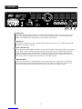
Rear Panel
16
17
19
16 17 23
18 19 20 21 22 24
18
20

11
Rear Panel
TUNER SEND
This output is provided for connection to electronic tuners (buffered signal). This output may also be
used as an unbalanced Direct Interface, or a buffered pass-through to use two amps simultaneously.
NOTE: The TUNER SEND is always ACTIVE, even when the amp is muted.
GROUND LIFT
This button is provided to prevent a ground loop that may result in "hum" noise. When depressed (IN
poisition), Ground Lift is engaged.
DIRECT INTERFACE (DI)
This is a built-in, balanced Direct Interface is used to send a buffered, unprocessed signal to an external
mixer. NOTE: The Direct Interface features failsafe circuitry, which runs on standard 48-volt phantom
power from the mixer. This allows the DI to continue functioning even in the event of a blown circuit
breaker or amplier shutdown. In the event of a failsafe operation, the mute switch will be bypassed.
This circuit is active, even when the power switch is in the "Off" position.
AUXILiARY INPUT
This input is provided for a convenient input of rack-mount processors. This input is for signal levels
only and overrides the high and low input jacks on the front of the unit. NOTE: For a clean look, the
bass may be plugged directly into this jack, but please note that this is a high gain input.
21
22
23
23
23
21 22 24

12
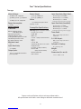
Tour™ Series Specications
Mains Voltage:
120 VAC 60 Hz - 6 amp fuse
230 VAC 50/60 Hz - 3.15 amp fuse
100 VAC 50/60 Hz - 8 amp fuse
Power Consumption:
600 W
Power Amplifier
Protection:
DDT™ speaker protection
with defeat switch
Short Circuit protection
Thermal protection circuit
Cooling fan failure protection circuit
Current limit protection circuit
DC output protection circuit
Minimum Load:
4 Ω
Input Sensitivity:
600 mVRMS
Output Jacks:
Two 1/4" Speakon® combination
jacks in parallel
Power Output:
300 w, 48.9 VRMS/8 Ω
450 w, 42.4 VRMS/4 Ω
Noise:
> 100 dB below full power @ 8 Ω
typically -105 dB
Preamplifier Specifications
Settings (unless otherwise stated):
Pre gain: 4 (12 o'clock)
Bright: Out
Mute: out
Contour: 0 (fully counterclockwise)
Low: 0
High: 0
Low Cut: Out
Graphic EQ: All sliders set to center
EQ Bypass: Out
Post Gain: 10 (fully clockwise)
Octaver: MIN
(fully counterclockwise)
Octaver Defeat: Out
DDT™: Active
Input Sensitivity (High Gain):
Nominal Input: 616 mVRMS
Minimum Input: 34.1 mVRMS
Maximum Input: 2.3 VRMS
(maximum signal at input before clipping)
Input Sensitivity (Low Gain):
Nominal Input: 1.0 VRMS
Minimum Input: 59.3 m VRMS
Maximum Input: 7.2 VRMS
(maximum signal at input before clipping)
Tuner Send:
Buffered from input jack with no
equalization
D.I. XLR Output:
Buffered from input jack with no
equalization
Failsafe D.I. Backup:
48 v phantom power
Weight:
21.8 lb.
Dimensions (h x w x d):
3.875 x 19.00 x 12.50
Tour 450
Features and specifications subject to change without notice.
All specifications tested with mains voltage maintained at nominal level.

13
Tour™ Series Specications
Mains Voltage:
120 VAC 60 Hz - 10 amp fuse
230 VAC 50/60 Hz - 6 amp fuse
100 VAC 50/60 Hz - 12 amp fuse
Power Consumption:
1000 W
Power Amplifier
Protection:
DDT™ speaker protection
with defeat switch
Short Circuit protection
Thermal protection circuit
Cooling fan failure protection circuit
Current limit protection circuit
DC output protection circuit
Minimum Load:
4 Ω
Input Sensitivity:
750 mVRMS
Output Jacks:
Two 1/4" Speakon® combination
jacks in parallel
Power Output:
500 w, 63.2 VRMS/8 Ω
700 w, 52.9 VRMS/4 Ω
Noise:
> 100 dB below full power @ 8 Ω
typically -105 dB
Preamplifier Specifications
Settings (unless otherwise stated):
Pre gain: 4 (12 o'clock)
Bright: Out
Mute: out
Contour: 0 (fully counterclockwise)
Low: 0
High: 0
Low Cut: Out
Graphic EQ: All sliders set to center
EQ Bypass: Out
Post Gain: 10 (fully clockwise)
Octaver: MIN
(fully counterclockwise)
Octaver Defeat: Out
DDT™: Active
Input Sensitivity (High Gain):
Nominal Input: 740 mVRMS
Minimum Input: 41.6 mVRMS
(pre gain fully counterclockwise)
Maximum Input: 2.3 VRMS
(maximum signal at input before clipping)
Input Sensitivity (Low Gain):
Nominal Input: 1.3 VRMS
Minimum Input: 72 m VRMS
(pre gain fully counterclockwise)
Maximum Input: 7.2 VRMS
(maximum signal at input before clipping)
Tuner Send:
Buffered from input jack with no
equalization
D.I. XLR Output:
Buffered from input jack with no
equalization
Failsafe D.I. Backup:
48 v phantom power
Weight:
24.0 lb.
Dimensions (h x w x d):
3.875 x 19.00 x 12.50
Tour 700
Features and specifications subject to change without notice.
All specifications tested with mains voltage maintained at nominal level.

14
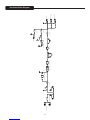
Tour Series Block Diagram
NOTCH
Graphic EQ
EQ
LO HI
HI PASS 2
1
2
1
Meridian, MS 39301
Peavey Electronics Corp.
P. O. Box 2898
4
3
2
1
D
4
3
2
1
CBA
A B C D
Sheet Title:
Title:
Sheet Date:
of
D
MUTE
SPEAKER OUTPUTS
POWER AMPLIFIER
OCTAVE DIVIDER CIRCUIT
DI XLR OUTPUTDIFF. AMP
TUNER SEND
AUX. INPUT
LOW GAIN INPUT
HIGH GAIN INPUT
CONTOURPRE GAIN
BUFFER
LOW CUT
POST GAIN
BRIGHT
TONE CONTROLS 9-BAND GRAPHIC EQ
SEND RETURN
BUFFER
MUTE
BLOCK
4-17-2006_10:002 2

15
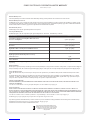
PEAVEY ELECTRONICS CORPORATION LIMITED WARRANTY
Effective Date: July 1, 1998
What This Warranty Covers
Your Peavey Warranty covers defects in material and workmanship in Peavey products purchased and serviced in the U.S.A. and Canada.
What This Warranty Does Not Cover
The Warranty does not cover: (1) damage caused by accident, misuse, abuse, improper installation or operation, rental, product modification or neglect; (2) dam-
age occurring during shipment; (3) damage caused by repair or service performed by persons not authorized by Peavey; (4) products on which the serial number
has been altered, defaced or removed; (5) products not purchased from an Authorized Peavey Dealer.
Who This Warranty Protects
This Warranty protects only the original retail purchaser of the product.
How Long This Warranty Lasts
The Warranty begins on the date of purchase by the original retail purchaser. The duration of the Warranty is as follows:
Product Category Duration
Guitars/Basses, Amplifiers, Pre-Amplifiers, Mixers, Electronic
Crossovers and Equalizers 2 years (+ 3 years)*
Drums 2 years (+ 1 year)*
Enclosures 3 years (+ 2 years)*
Digital Effect Devices and Keyboard and MIDI Controllers 1 year (+ 1 year)*
Microphones 2 years
Speaker Components (incl. speakers, baskets, drivers,
diaphragm replacement kits and passive crossovers)
and all Accessories 1 year
Tubes and Meters 90 days
[*Denotes additional warranty period applicable if optional Warranty Registration Card is completed and returned to Peavey by original retail purchaser within 90 days
of purchase.]
What Peavey Will Do
We will repair or replace (at Peavey's discretion) products covered by warranty at no charge for labor or materials. If the product or component must be shipped to
Peavey for warranty service, the consumer must pay initial shipping charges. If the repairs are covered by warranty, Peavey will pay the return shipping charges.
How To Get Warranty Service
(1) Take the defective item and your sales receipt or other proof of date of purchase to your Authorized Peavey Dealer or Authorized Peavey Service Center.
OR
(2) Ship the defective item, prepaid, to Peavey Electronics Corporation, International Service Center, 412 Highway 11 & 80 East, Meridian, MS 39301 or Peavey
Canada Ltd., 95 Shields Court, Markham, Ontario, Canada L3R 9T5. Include a detailed description of the problem, together with a copy of your sales receipt or
other proof of date of purchase as evidence of warranty coverage. Also provide a complete return address.
Limitation of Implied Warranties
ANY IMPLIED WARRANTIES, INCLUDING WARRANTIES OF MERCHANTABILITY AND FITNESS FOR A PARTICULAR PURPOSE, ARE LIMITED IN DURATION TO THE
LENGTH OF THIS WARRANTY.
Some states do not allow limitations on how long an implied warranty lasts, so the above limitation may not apply to you.
Exclusions of Damages
PEAVEY'S LIABILITY FOR ANY DEFECTIVE PRODUCT IS LIMITED TO THE REPAIR OR REPLACEMENT OF THE PRODUCT, AT PEAVEY'S OPTION. IF WE ELECT TO
REPLACE THE PRODUCT, THE REPLACEMENT MAY BE A RECONDITIONED UNIT. PEAVEY SHALL NOT BE LIABLE FOR DAMAGES BASED ON INCONVENIENCE, LOSS OF
USE, LOST PROFITS, LOST SAVINGS, DAMAGE TO ANY OTHER EQUIPMENT OR OTHER ITEMS AT THE SITE OF USE, OR ANY OTHER DAMAGES WHETHER INCIDENTAL,
CONSEQUENTIAL OR OTHERWISE, EVEN IF PEAVEY HAS BEEN ADVISED OF THE POSSIBILITY OF SUCH DAMAGES.
Some states do not allow the exclusion or limitation of incidental or consequential damages, so the above limitation or exclusion may not apply to you.
This Warranty gives you specific legal rights, and you may also have other rights which vary from state to state.
If you have any questions about this warranty or service received or if you need assistance in locating an Authorized Service Center, please contact the Peavey
International Service Center at (601) 483-5365 / Peavey Canada Ltd. at (905) 475-2578.
Features and specifications subject to change without notice.
Logo referenced in Directive 2002/96/EC Annex IV
(OJ(L)37/38,13.02.03 and defined in EN 50419: 2005
The bar is the symbol for marking of new waste and
is applied only to equipment manufactured after
13 August 2005

-
 1
1
-
 2
2
-
 3
3
-
 4
4
-
 5
5
-
 6
6
-
 7
7
-
 8
8
-
 9
9
-
 10
10
-
 11
11
-
 12
12
-
 13
13
-
 14
14
-
 15
15
-
 16
16


Peavey Tour 700 Instrucciones de operación
- Categoría
- Equipo de música suplementario
- Tipo
- Instrucciones de operación
en otros idiomas
- français: Peavey Tour 700 Mode d'emploi
- English: Peavey Tour 700 Operating instructions
- Deutsch: Peavey Tour 700 Bedienungsanleitung
Artículos relacionados
-
Peavey XR8600 Manual de usuario
-
-
-
 Peavy PV Series Power Amplifer El manual del propietario
-
 Peavy KB 3 60-Watt 1x12 Keyboard Amp El manual del propietario
-
-
 Peavy 1400 Manual de usuario
-
Peavy IPR2 2000 Manual de usuario
-
-
Peavy KB4 El manual del propietario


