Yamaha n12 El manual del propietario
- Categoría
- Equipo musical
- Tipo
- El manual del propietario
Este manual también es adecuado para

ES
FR
DE
EN
Owner's Manual
Bedienungsanleitung
Mode d'emploi
Manual de instrucciones
EnglishDeutschFrançaisEspañol

The above warning is located on the rear of the unit.
Explanation of Graphical Symbols
The lightning flash with arrowhead symbol
within an equilateral triangle is intended to alert
the user to the presence of uninsulated
“dangerous voltage” within the product’s
enclosure that may be of sufficient magnitude to
constitute a risk of electric shock to persons.
The exclamation point within an equilateral
triangle is intended to alert the user to the
presence of important operating and
maintenance (servicing) instructions in the
literature accompanying the product.
IMPORTANT SAFETY INSTRUCTIONS
1 Read these instructions.
2Keep these instructions.
3 Heed all warnings.
4 Follow all instructions.
5 Do not use this apparatus near water.
6 Clean only with dry cloth.
7 Do not block any ventilation openings. Install in
accordance with the manufacturer’s instructions.
8 Do not install near any heat sources such as radiators,
heat registers, stoves, or other apparatus (including
amplifiers) that produce heat.
9 Do not defeat the safety purpose of the polarized or
grounding-type plug. A polarized plug has two blades
with one wider than the other. A grounding type plug
has two blades and a third grounding prong. The wide
blade or the third prong are provided for your safety. If
the provided plug does not fit into your outlet, consult
an electrician for replacement of the obsolete outlet.
10 Protect the power cord from being walked on or pinched
particularly at plugs, convenience receptacles, and the
point where they exit from the apparatus.
11 Only use attachments/accessories specified by the
manufacturer.
12 Use only with the cart, stand,
tripod, bracket, or table specified
by the manufacturer, or sold with
the apparatus. When a cart is
used, use caution when moving
the cart/apparatus combination
to avoid injury from tip-over.
13 Unplug this apparatus during
lightning storms or when unused for long periods of
time.
14 Refer all servicing to qualified service personnel.
Servicing is required when the apparatus has been
damaged in any way, such as power-supply cord or plug
is damaged, liquid has been spilled or objects have
fallen into the apparatus, the apparatus has been
exposed to rain or moisture, does not operate normally,
or has been dropped.
(98-6500)
CAUTION: TO REDUCE THE RISK OF
ELECTRIC SHOCK, DO NOT REMOVE
COVER (OR BACK). NO USER-SERVICEABLE
PARTS INSIDE. REFER SERVICING TO
QUALIFIED SERVICE PERSONNEL.
CAUTION
RISK OF ELECTRIC SHOCK
DO NOT OPEN
WARNING
TO REDUCE THE RISK OF FIRE OR ELECTRIC SHOCK, DO NOT EXPOSE THIS APPARATUS TO RAIN OR MOISTURE.

1. IMPORTANT NOTICE: DO NOT MODIFY THIS UNIT!
This product, when installed as indicated in the instructions con-
tained in this manual, meets FCC requirements. Modifications not
expressly approved by Yamaha may void your authority, granted by
the FCC, to use the product.
2. IMPORTANT:
When connecting this product to accessories and/
or another product use only high quality shielded cables. Cable/s
supplied with this product MUST be used. Follow all installation
instructions. Failure to follow instructions could void your FCC
authorization to use this product in the USA.
3. NOTE:
This product has been tested and found to comply with the
requirements listed in FCC Regulations, Part 15 for Class “B” digital
devices. Compliance with these requirements provides a reason-
able level of assurance that your use of this product in a residential
environment will not result in harmful interference with other elec-
tronic devices. This equipment generates/uses radio frequencies
and, if not installed and used according to the instructions found in
the users manual, may cause interference harmful to the operation
of other electronic devices. Compliance with FCC regulations does
* This applies only to products distributed by YAMAHA CORPORATION OF AMERICA. (class B)
not guarantee that interference will not occur in all installations. If
this product is found to be the source of interference, which can be
determined by turning the unit “OFF” and “ON”, please try to elimi-
nate the problem by using one of the following measures:
Relocate either this product or the device that is being affected by
the interference.
Utilize power outlets that are on different branch (circuit breaker or
fuse) circuits or install AC line filter/s.
In the case of radio or TV interference, relocate/reorient the
antenna. If the antenna lead-in is 300 ohm ribbon lead, change the
lead-in to co-axial type cable.
If these corrective measures do not produce satisfactory results,
please contact the local retailer authorized to distribute this type of
product. If you can not locate the appropriate retailer, please con-
tact Yamaha Corporation of America, Electronic Service Division,
6600 Orangethorpe Ave, Buena Park, CA90620
The above statements apply ONLY to those products distributed by
Yamaha Corporation of America or its subsidiaries.
FCC INFORMATION (U.S.A.)
The serial number of this product may be found on the rear of
the unit. You should note this serial number in the space pro-
vided below and retain this manual as a permanent record of
your purchase to aid identification in the event of theft.
Model No.
Serial No.
(rear)
* This applies only to products distributed by
YAMAHA CORPORATION OF AMERICA.
COMPLIANCE INFORMATION STATEMENT
(DECLARATION OF CONFORMITY PROCEDURE)
Responsible Party : Yamaha Corporation of America
Address : 6600 Orangethorpe Ave., Buena Park, Calif. 90620
Telephone : 714-522-9011
Type of Equipment : Digital Mixing Studio
Model Name : n8/n12
This device complies with Part 15 of the FCC Rules.
Operation is subject to the following conditions:
1) this device may not cause harmful interference, and
2) this device must accept any interference received including interference
that may cause undesired operation.
See user manual instructions if interference to radio reception is suspected.
(FCC DoC)
OBSERVERA!
Apparaten kopplas inte ur växelströmskällan (nätet) så länge
som den ar ansluten till vägguttaget, även om själva apparaten
har stängts av.
ADVARSEL:
Netspæendingen til dette apparat er IKKE
afbrudt, sålæenge netledningen siddr i en stikkontakt, som er t
endt — også selvom der or slukket på apparatets afbryder.
VAROITUS:
Laitteen toisiopiiriin kytketty käyttökytkin ei irroita
koko laitetta verkosta.
(standby)
IMPORTANT
Please record the serial number of this unit in the space below.
Model:
Serial No.:
The serial number is located on the bottom or rear of the unit.
Retain this Owner's Manual in a safe place for future
reference.
(Ser. No)* This applies only to products distributed by
YAMAHA CORPORATION OF AMERICA
IMPORTANT NOTICE FOR THE UNITED KINGDOM
Connecting the Plug and Cord
IMPORTANT. The wires in this mains lead are coloured in accordance
with the following code:
BLUE : NEUTRAL
BROWN : LIVE
As the colours of the wires in the mains lead of this apparatus may not
correspond with the coloured makings identifying the terminals in your
plug proceed as follows:
The wire which is coloured BLUE must be connected to the terminal
which is marked with the letter N or coloured BLACK.
The wire which is coloured BROWN must be connected to the termi-
nal which is marked with the letter L or coloured RED.
Making sure that neither core is connected to the earth terminal of the
three pin plug.
• This applies only to products distributed by Yamaha-Kemble Music (U.K.) Ltd. (2 wires)

Owner’s Manual
4
English
Welcome .......................................... 5
Features ........................................... 5
Included items (please check) ....... 5
Turning On and Off the Power to the
Mixer ................................................ 8
Before Turning On the Power to the Mixer .............. 8
Turning the Power On and Off ................................ 8
Recording Basics ............................ 9
Techie Words? Don’t Be Afraid. .............................. 9
Signals — Level and Decibel ............................ 9
Balanced or Unbalanced? ................................ 9
How balanced lines work .................................. 9
How unbalanced lines work ............................ 10
Connector Variations ....................................... 10
Phone connectors ........................................... 10
RCA pin connectors ........................................ 10
Inside Your Mixer .................................................. 11
Basic Structure ................................................ 11
Monitor mix for musicians, external effects ..... 12
Front and Rear Panels ................... 13
Channel Control section ........................................ 13
Master Control section .......................................... 16
Meter section ......................................................... 17
Control Room section ............................................ 18
DAW Remote Control section ............................... 19
Rear I/O section .................................................... 20
Setting Up the Mixer ..................... 22
Setup Procedure ................................................... 22
n12 Setup Example (Home recording) .................. 22
n8 Setup Example (Home recording) .................... 23
Installing Monitor Speakers ................................... 23
A Hands-On Guide to the n8/n12 ... 24
Let’s Hear It! .......................................................... 24
Connecting sound sources and monitor devices
24
Adjusting the gain ........................................... 24
Setting up the monitoring environment ........... 25
Adjusting the volume level .............................. 26
Making Great Mixes .............................................. 28
Manipulating compression .............................. 28
Mastery of EQ .................................................. 29
Panning and balancing ................................... 30
Mixing into stereo ............................................ 30
Applying reverb ............................................... 31
Soloing a channel ............................................ 32
Using the n8/n12 with
Cubase 4 series ............................ 33
What you can do using the n8/n12 with Cubase ... 33
Computer setup for the Link function .................... 34
Using the Link Function ......................................... 36
Remotely controlling the Cubase transport section
and audio tracks ............................................. 36
Remotely adjusting the click sound (metronome)
36
Selecting the Work mode ................................ 36
Let’s start our recording session! .......................... 39
Mixing signals on the n8/n12, then recording . 39
Recording n8/n12 input channel signals directly to
Cubase ............................................................ 41
Mixing recorded tracks .......................................... 43
Mixing audio tracks ......................................... 43
Mixing down .................................................... 45
Monitoring in a Surround Sound
Environment (n12 only) .................. 46
Connecting surround speakers ............................. 46
Placement of the surround speakers .................... 46
Setting up surround monitoring ............................. 47
Replacing the Sweet Spot Data .... 48
Using the n8/n12 with Software Other
Than Cubase .................................. 49
Using the n8/n12 with a DAW other than Cubase . 49
Audio Driver Setup .......................................... 49
MIDI Driver Setup ............................................ 49
Using the n8/n12 along with a multimedia application
51
Troubleshooting ............................. 53
While using the mixer ............................................ 53
While using the mixer with a computer ................. 53
Error Messages ..................................................... 55
Index .............................................. 56
Appendix ........................................ 57
Specifications ........................................................ 57
Bus connections of n8/n12 and DAW ................... 60
Dimensional Diagrams .......................................... 63
Block Diagram ....................................................... 64
MIDI Implementation Chart ................................... 65
Table of Contents

Welcome
Owner’s Manual
5
English
Thank you for purchasing the Yamaha n8/n12 Digital Mixing Studio. The n8/n12 is a comprehensive music production system
that packages a digital mixer featuring easy yet full-fledged recording/mixdown operations with the cutting-edge DAW software
Cubase AI 4. Connecting a computer to the mixer’s IEEE 1394 port enables you to configure an ideal recording environment.
Please read this Owner’s Manual before you start using the n8/n12 so that you can take full advantage of the mixer’s superlative
features and enjoy trouble-free operation for years to come. Also, keep this book in a safe place for future reference.
Ease of operation
Analog-like mixing interface ensures intuitive operation.
High-quality sound
Based on an examination of existing head amp circuits, a new head amp circuit has been developed to provide higher
quality and superior musical characteristics.
Mixer functions
The mixer can handle up to 16 channel inputs (n12) or 12 channel inputs (n8), mixing them to stereo outputs. Each
monaural input jack features an XLR jack with a phantom power supply, which enables you to connect a wide range of
instruments and devices, from condenser microphones to synthesizers and other line-level instruments. Input channel 8
(n12) and Input channel 4 (n8) support Hi-Z input for direct connection of an electric guitar or bass.
Computer connection via a single IEEE 1394 cable
Connect a computer with an IEEE 1394 port to the n8/n12 using an IEEE 1394 cable to transfer audio and MIDI signals
between the mixer and Steinberg Cubase or other DAW.
* In order to monitor in a surround environment, you will need a surround-capable application such as Cubase 4. The included
Cubase AI 4 does not support surround.
Link with Cubase
Install Cubase AI 4 on the computer, and the n8/n12 will link to Cubase and operate together seamlessly. For example, you
can record the n8/n12 input signals to Cubase as is, or mix Cubase audio tracks on the n8/n12. You can also turn on and
off the monitor for the VST effects or control the transport section and tracks remotely from the n8/n12. In addition, Purchase
the separately-available Cubase 4 and use it with the n8/n12 to enjoy advanced functionality such as surround.
Control Room monitoring function
The n8/n12 features a monitoring function dedicated to the Control Room (Control Room Monitor function). You can
connect one (n8) or three (n12) monitoring speakers to the mixer. If a computer is connected to the n12, you can
monitor the sound from Cubase or another DAW in a surround sound environment.
Newly developed compressor
The n8/n12 includes a newly developed compressor that adopts Sweet Spot Morphing technology. The mixer provides
various compressor presets that represent the distillation of extensive professional engineering experience, letting you
quickly and easily bring your sound to a professional standard.
Three-band EQ on each channel
Each input channel features a full 3-band (high/mid/low) equalizer, providing easy sound shaping to suit your preferences.
Digital reverb at your service
A built-in digital reverb can be assigned to all input channels. If a computer is connected to the mixer, you can also apply
digital reverberation to output from Cubase or another DAW, as well as to microphone and other instrumental sounds.
Power adaptor (n12= PA-30, n8=PA-20)*
* May not be included depending on your particular
area. Please check with your Yamaha dealer.
Owner’s Manual
IEEE 1394 cable
TOOLS for n Version2/Cubase AI 4 installation guide
TOOLS for n Version2 CD-ROM
Cubase AI 4 DVD-ROM
Welcome
Features
Included items (please check)
Please read the software license agreement before
you unseal the included discs. The software license
agreement is given at the end of the TOOLS for n
Version2/Cubase AI 4 installation guide.
NOTE

PRECAUTIONS
Owner’s Manual
6
English
PRECAUTIONS
PLEASE READ CAREFULLY BEFORE PROCEEDING
* Please keep this manual in a safe place for future reference.
WARNING
Always follow the basic precautions listed below to avoid the possibility of serious injury or even death from electrical
shock, short-circuiting, damages, fire or other hazards. These precautions include, but are not limited to, the following:
• Only use the voltage specified as correct for the device. The required voltage is
printed on the name plate of the device.
• Use only the included AC power adaptor (*PA-30 for the n12, PA-20 for the n8
or an equivalent recommended by Yamaha).
• Do not place the power cord near heat sources such as heaters or radiators,
and do not excessively bend or otherwise damage the cord, place heavy objects
on it, or place it in a position where anyone could walk on, trip over, or roll
anything over it.
• Do not open the device or attempt to disassemble the internal parts or modify
them in any way. The device contains no user-serviceable parts. If it should
appear to be malfunctioning, discontinue use immediately and have it
inspected by qualified Yamaha service personnel.
• Do not expose the device to rain, use it near water or in damp or wet
conditions, or place containers on it containing liquids which might spill into
any openings.
If any liquid such as water seeps into the device, turn off the power immediately
and unplug the power cord from the AC outlet. Then have the device inspected
by qualified Yamaha service personnel.
• Never insert or remove an electric plug with wet hands.
• If the power cord or plug becomes frayed or damaged, or if there is a sudden
loss of sound during use of the device, or if any unusual smells or smoke
should appear to be caused by it, immediately turn off the power switch,
disconnect the electric plug from the outlet, and have the device inspected by
qualified Yamaha service personnel.
• If this device or the AC power adaptor should be dropped or damaged,
immediately turn off the power switch, disconnect the electric plug from the
outlet, and have the device inspected by qualified Yamaha service personnel.
CAUTION
Always follow the basic precautions listed below to avoid the possibility of physical injury to you or others, or damage
to the device or other property. These precautions include, but are not limited to, the following:
• Remove the electric plug from the outlet when the device is not to be used for
extended periods of time, or during electrical storms.
• When removing the electric plug from the device or an outlet, always hold the
plug itself and not the cord. Pulling by the cord can damage it.
•To avoid generating unwanted noise, make sure there is adequate distance
between the AC power adaptor and the device.
• Do not cover or wrap the AC power adaptor with a cloth or blanket.
• Before moving the device, remove all connected cables.
• When setting up the device, make sure that the AC outlet you are using is easily
accessible. If some trouble or malfunction occurs, immediately turn off the
power switch and disconnect the plug from the outlet. Even when the power
switch is turned off, electricity is still flowing to the product at the minimum
level. When you are not using the product for a long time, make sure to unplug
the power cord from the wall AC outlet.
•Avoid setting all equalizer controls and faders to their maximum. Depending on
the condition of the connected devices, doing so may cause feedback and may
damage the speakers.
• Do not expose the device to excessive dust or vibrations, or extreme cold or
heat (such as in direct sunlight, near a heater, or in a car during the day) to
prevent the possibility of panel disfiguration or damage to the internal
components.
• Do not place the device in an unstable position where it might accidentally fall
over.
• Do not block the vents. This device has ventilation holes at the top/bottom to
prevent the internal temperature from becoming too high. In particular, do not
place the device on its side or upside down. Inadequate ventilation can result in
overheating, possibly causing damage to the device(s), or even fire.
• Do not use the device in the vicinity of a TV, radio, stereo equipment, mobile
phone, or other electric devices. Doing so may result in noise, both in the
device itself and in the TV or radio next to it.
• Before connecting the device to other devices, turn off the power for all devices.
Before turning the power on or off for all devices, set all volume levels to
minimum.
Power supply/Power cord
Do not open
Water warning
If you notice any abnormality
Power supply/Power cord
Location
Connections

PRECAUTIONS
Owner’s Manual
7
English
• Remove the power plug from the AC outlet when cleaning the device.
• When turning on the AC power in your audio system, always turn on the power
amplifier LAST, to avoid speaker damage. When turning the power off, the
power amplifier should be turned off FIRST for the same reason.
• Do not insert your fingers or hands in any gaps or openings on the device
(vents, ports, etc.).
•Avoid inserting or dropping foreign objects (paper, plastic, metal, etc.) into any
gaps or openings on the device (vents, ports, etc.) If this happens, turn off the
power immediately and unplug the power cord from the AC outlet. Then have
the device inspected by qualified Yamaha service personnel.
• Do not apply oil, grease, or contact cleaner to the faders. Doing so may cause
problems with electrical contact or fader motion.
• Do not use the device or headphones for a long period of time at a high or
uncomfortable volume level, since this can cause permanent hearing loss. If
you experience any hearing loss or ringing in the ears, consult a physician.
• Do not rest your weight on the device or place heavy objects on it, and avoid
use excessive force on the buttons, switches or connectors.
Always turn the power off when the device is not in use.
Even when the power switch is in the “STANDBY” position, electricity is still flowing to the device at the minimum level. When you are not using the device for a long time,
make sure you unplug the power cord from the wall AC outlet.
The performance of components with moving contacts, such as switches, volume controls, and connectors, deteriorates over time. Consult qualified Yamaha service
personnel about replacing defective components.
The illustrations and LCD screens as shown in this owner’s manual are for instructional purposes only, and may appear somewhat different from those on your instrument.
This product incorporates and bundles computer programs and contents in which Yamaha owns copyrights or with respect to which it has license to use others' copyrights.
Such copyrighted materials include, without limitation, all computer software, music data, etc. Any unauthorized use of such programs and contents outside of personal use
is not permitted under relevant laws. Any violation of copyright has legal consequences. DON'T MAKE, DISTRIBUTE OR USE ILLEGAL COPIES.
Copying of the commercially available musical data including but not limited to MIDI data and/or audio data is strictly prohibited except for your personal use.
• Windows is the registered trademarks of Microsoft(R) Corporation.
• Apple, Mac and Macintosh are trademarks of Apple Inc., registered in the U.S. and other countries.
• FireWire and the FireWire symbol are trademarks of Apple, Inc., registered in the U.S. and other countries. The FireWire logo is a trademark of Apple, Inc.
• Steinberg and Cubase are the registered trademarks of Steinberg Media Technologies GmbH.
• The company names and product names in this Owner’s Manual are the trademarks or registered trademarks of their respective companies.
Maintenance
Handling caution
XLR-type connectors are wired as follows (IEC60268 standard): pin 1: ground, pin 2: hot (+), and pin 3: cold (-).
Insert TRS phone jacks are wired as follows: sleeve: ground, tip: send, and ring: return.
Yamaha cannot be held responsible for damage caused by improper use or modifications to the device, or data that is lost or destroyed.

Turning On and Off the Power to the Mixer
Owner’s Manual
8
English
Before Turning On the
Power to the Mixer
1.
Make sure that the mixer’s power switch is in the
STANDBY position.
2.
Connect the power adaptor to the AC INPUT
connector (
1
) on the rear panel of the mixer,
then turn the fastening ring clockwise (
2
) to
secure the connection.
3.
Connect the power adaptor to a standard
household power outlet securely.
Turning the Power On and
Off
1.
To turn the power on, press the mixer’s power
switch to the ON position.
2.
To turn the power off, press the power switch to
the STANDBY position.
Tur ning On and Off the Power to the Mixer
Warning
Use only the included power adaptor (*PA-30 for the n12, PA-
20 for the n8 or an equivalent recommended by Yamaha). Use
of a different adaptor may result in equipment damage,
overheating, or fire. In such cases, the product warranty will be
void immediately even within the effective warranty period.
Caution
• Be sure to unplug the adaptor from the outlet when you are
not using the mixer, or when lightning storms are expected in
your area.
• Make sure that there is adequate distance between the
power adaptor and the mixer. Otherwise, noise may be
generated.
2
1
Caution
Note that a small amount of current continues to flow while the
switch is in the STANDBY position. If you do not plan to use the
mixer for an extended period of time, please be sure to unplug
the adaptor from the wall outlet.
To prevent sudden loud sounds from being
produced from your speakers, power-on your
equipment starting at the audio source (instrument,
mic, CD player, etc.) and working downstream.
Example:
Instruments, mics, CD players, and other
peripheral devices
→
n8/n12
→
Powered speakers
(power amps)
When turning the power off, reverse the above
sequence.
NOTE

Recording Basics
Owner’s Manual
9
English
Techie Words? Don’t Be Afraid.
Signals — Level and Decibel
Assume the softest sound a human being can hear is at
a level of “1,” and the loudest sound a human being can
endure hearing is at a level of “1,000,000.” The
difference expressed in these numbers is huge, and
you have to use too many digits to express the level.
This is very inconvenient. So, we use a term or unit
called “decibel (dB),” defining the normal level
difference between the softest and loudest sounds
detectable by human hearing to be 120 dB.
A decibel is a relative value based on a reference level
of 0 dB. Audio devices usually treat audio as electrical
signals. There are various types of decibel
measurements: dBu, dBV, dBm, etc., but the most
popular one is dBu, which is based on 0.775V as the
reference level (0 dBu). The output level of a
microphone is very low –– about several millivolts (–60
dBu — –30 dBu). On the other hand, the maximum
output of a mixer can be 12 V (+24 dBu).
To create clear sounds, a signal should be input to a
mixer at an appropriate level. When you connect audio
devices to your mixer, be sure to match the nominal
input of an instrument to the output level of the mixer,
then adjust the input level with the mixer’s gain control.
Balanced or Unbalanced?
In most cases, shielded cables are used to transfer
signals between audio devices. Shielded cables are
divided into two types: balanced and unbalanced.
Balanced lines are very good at rejecting noise, and
they are the best choice for long cable runs or for
transferring very weak signals. Unbalanced cables are
usually used for line-level signals.
Microphone:
Use balanced lines.
Short line-level runs:
Unbalanced lines are fine.
Long line-level runs:
Use balanced lines.
We are constantly surrounded by random electromagnetic
radiation (noise), such as radio and TV signals as well as
spurious electromagnetic noise generated by power lines,
motors, electric appliances, computers, and other
sources. The longer the wire, the more noise it is likely to
pick up. To avoid noise, use the shortest cable possible.
How balanced lines work
A cable that features an XLR plug on each end is a
balanced line. It consists of hot (+), cold (–), and
ground conductors.
A device transmits an original hot (+) signal through the
hot conductor and the same, but inverted, signal
through the cool (–) conductor to the destination. The
receiving device inverts the inverted signal back to
normal and combines it with the original hot signal.
Any noise induced in the line will be exactly the same in
both conductors, and thus in phase. The trick is that the
phase of one signal (through the cool (–) conductor) is
reversed at the receiving end of the line so that the
desired audio signals become in-phase, and the
induced noise suddenly finds itself out of phase. The
out-of-phase noise signal is effectively canceled while
the audio signal is left intact.
Recording Basics
+ 20 dBu
0 dBu
0.775 V
-
20 dBu
-
40 dBu
-
60 dBu
Professional audio gear, such as a
mixer or a power amplifier, features
line inputs and outputs with a
nominal level of +4 dBu.
Keyboards and other line instruments
have line inputs and outputs with a
nominal level of –10 dBu.
Microphone levels vary depending
on the sound source. Speech is at
about –30 dBu. Bird chirping is
lower than –50 dBu. Closely
recorded drums could reach 0 dBu.
input signal
gain
control
output signal
too high
appropriate
level
too low
Anatomy of a shielded cable
As shown in the illustration above, a shielded cable
consists of one hot (and cold conductor) wrapped in a
metal net (shield, or ground conductor). The ground
functions as a barrier against noise, protecting the
signal from noise that may be induced in the line.
hot
cold
shield
(ground)
jacket
balanced unbalanced

Recording Basics
Owner’s Manual
10
English
This is why balanced lines excel at rejecting noise.
How unbalanced lines work
Unbalanced connectors and cables are less expensive
than balanced cables. If the level of signals to be
transmitted is very high and/or the signal is not
susceptible to noise, or all connections are very short,
you can use unbalanced lines.
Monaural phone jacks and RCA pin jacks (which are
often used for consumer AV gear) are always
unbalanced. On an unbalanced line, signals travel
through a hot (+) conductor and a ground (GND)
conductor (which is a combination of cold and ground
conductors). Therefore, an unbalanced line does not
feature noise canceling (unlike a balanced cable).
However, the output signal level through unbalanced
jacks is usually high enough that using unbalanced
lines is just fine. You can also convert unbalanced
signals into balanced signals using a DI
(*)
.
(*)
A DI is a direct injection box that converts unbalanced
signals into balanced signals. For example, if you
connect an electric guitar to a mixer directly, the sound
may be thin or noise may be induced. In this case, you
can connect a DI between the instrument and the
mixer to convert the signal into a balanced one and
avoid a thin, noisy sound.
Connector Variations
Audio devices feature various types of connectors.
Questions you are likely to encounter when setting up a
system for the first time might include “Why all these
different types of connectors on the back of my mixer?”
and “What is the difference between various types of
connectors?”
Let’s start by taking a look at the most common types of
connectors.
XLR-type connectors
An XLR-type connector, which supports balanced lines,
is sturdy and less susceptible to deformation. The plug
features a lock mechanism, so even if you pull the
cable, it will not be disconnected. It is often used in
professional environments that demand a high level of
reliability.
When you connect an XLR cable, the ground conductor
on the XLR plug and XLR jack comes in contact first.
Therefore, unlike with an RCA pin cable or phone cable,
you can avoid pop noises when connecting an XLR
cable. Usually, male plugs will output and female plugs
will input.
Phone connectors
The name “phone” arose simply because this
configuration was first used in telephone switchboards.
Phone jacks can be stereo or monaural. A stereo phone
jack is also referred to as a “TRS” phone jack, and is set
up to handle stereo signals, such as for headphones,
and insert I/O signals. A stereo phone jack can also
handle balanced signals. A monaural phone jack is
unbalanced, and can be used to connect an electric
guitar or other instruments, to an amplifier.
RCA pin connectors
This type of unbalanced pin jack has been widely used
on home audio/video equipment for many years. The
plugs are color coded according to the signals they
carry. A white plug is used for the left audio channel,
and a red plug is used for the right audio channel.
noise
hot (+)
cold (–)
ground
(GND)
transmitter cable receiver
noise canceling
phase
inversion
phase
inversion
synthesized
signal
noise
transmitter cable receiver
male female
stereo/TRS phone plug mono phone plug
white
red

Recording Basics
Owner’s Manual
11
English
Inside Your Mixer
Basic Structure
The purpose of configuring an audio system around a
mixer is to collect signals from all channels and mix to
achieve a good balance. Here is a greatly simplified
block diagram of a mixer to help you understand the
signal path.
Simplified mixer block diagram
■ Input channel
1 Head amp
The very first stage in any mixer through which the
input signal flows. The head amp features a gain
control that enables you to adjust the mixer’s input
sensitivity to match the level of the source.
You can amplify small signals, and attenuate large
signals.
2 Compressor/Equalizer
This stage enables you to process the input signal.
A compressor attenuates the peak level of the input
signal, and raises the overall signal level at the same
time, to lessen the level difference and raise the
sound pressure.
An equalizer adjusts the tone by boosting
(amplifying) or cutting (attenuating) certain
frequency ranges. You can use an equalizer to
change the tone to suit the acoustic environment of
a particular room, or to create a new sound. An
equalizer could be a high pass filter that cuts the
sound below a specified frequency.
Some mixers feature compressors and/or equalizers,
and some do not.
3 Level meter (input channel)
If the signal level is too high for the head amp or
compressor/equalizer to handle, the sound will clip
and be distorted. An input channel level meter enables
you to monitor this signal level. Some mixers feature a
channel peak LED that indicates only the peak level.
If the input signal is overloaded, adjust the head
amp gain control.
Most mixers have multiple level meters (including the
indicators). It is important to know the mixer stage for
which the meters are indicating signal levels.
4 Channel fader
A channel fader enables you to adjust the level of
the corresponding input channel signal that is going
to be routed to the buses (excluding a pre-fader
signal).
This control is most often used during mixing.
■ Bus
5 Bus
Input channel signals are routed to buses, mixed
together there, then output in stereo (master).
Buses are categorized into a few types based on their
purpose: stereo bus for stereo mix, AUX bus for AUX
send, etc. Using the appropriate buses is one of the
keys to basic mixing.
The n8/n12 features the following buses:
• STEREO bus (L/R)
• AUX bus (L/R)
• REC bus (L/R)
• REVERB bus (L/R)
• SOLO bus (L/R)
■ Master section
6 Stereo (master) fader
The master section enables you to adjust the level of
signals routed from buses.
Use a stereo master fader to adjust the level of the
mixer’s main output from the stereo buses.
Depending on the design of the mixer, a fader is
provided for each bus so that you can adjust the
level of each bus output.
7 Level meter (master)
This meter indicates the signal level in the master
section, which is the mixer’s final output level.
IN
OUT
BUS
1 2 3 4 5 6 7
COMP
EQ
input channel bus
master
section
bus

Recording Basics
Owner’s Manual
12
English
Monitor mix for musicians,
external effects
One important mixer function is to send out signals for
signal processing via an external effect unit or to be
monitored by the musicians. For these purposes, mixers
feature AUX bus and Insert I/O.
■ AUX buses for monitor sends
and overall effects
AUX (Auxiliary) buses are very convenient buses that
can be used for various purposes, such as: a) to create
a monitor mix that is separate from the main mix and
sent to the players for monitoring, and b) to process the
signal via an external effect unit and then bring it back
into the mix.
When you are using the AUX buses, you need to
consider whether you want a “pre-fader” signal (a signal
taken from a point before the channel fader) or a “post-
fader” signal (a signal taken from a point after the
channel fader) to be sent to the AUX buses.
On the n8/n12, a pre-fader signal is sent to the AUX
bus. Thus the bus signal is not affected by the channel
fader.
• Using AUX buses to create a monitor mix for players
Players prefer a pre-fader signal that maintains a proper
level balance. Since the pre-fader signal is sent to the
AUX bus on the n8/n12, even if you raise the input
channel fader for guitar during the guitar solo, the fader
operation does not affect the AUX bus output, which
remains independent of the main mix.
If a post-fader signal is routed to the AUX buses for
monitoring, the fader operation will affect the balance of
the monitor mix. This is something that you and the
players would probably like to avoid.
• Using AUX buses to process the signal via an
external effect unit
If you are using an AUX bus to send a pre-fader signal
to an external effect unit, you can adjust the level of the
input channel signal and the amount of effect
separately.
For example, if you operate the fader for the input
channel signal that is sent to the effect unit, the balance
between the dry signal (unprocessed) and the wet
signal (processed by the effect unit) will change. To
maintain the same balance between the dry and wet
signals, you must adjust the AUX send level whenever
you adjust the channel fader.
■ Insert I/O for processing
individual channel signals
Insert I/O jacks function in a manner similar to the AUX
buses: they provide a send and a return for signal
processing via an external effect unit. However, unlike
AUX buses that “collect multiple channel signals, then
send them together to an effect unit,” insert I/O jacks
are used to “send an individual channel signal to an
external effect unit, then return it to the mixer.”
A channel signal that is routed to the insert out jack has
already been amplified or attenuated to an appropriate
level via the gain control. Connect a compressor, limiter,
equalizer or other effect unit that can control the overall
signal to the insert I/O jacks.
You can also connect a reverb or similar effect unit to
process only a single channel signal.
When you connect an effect unit to the insert I/O jacks,
the channel signal will be routed to the external effect
unit via the insert out jack. The signal will be processed
by the effect unit, then returned to the mixer via the
insert in jack. It then resumes its normal path.
PRE
ON
OU
T
OU
T
AUX BUS
STEREO BUS
channel
fader
stereo fader
AUX send level
■ Built-in digital reverb
The n8/n12 features a REVERB bus that is dedicated
to the built-in digital reverb. This is almost identical to
the AUX bus, and can be used to send signals to the
built-in digital reverb.
The only difference from the AUX bus is that a post-
fader signal is routed to the REVERB bus. Therefore,
the send level is affected by the channel fader, so
the effect level always remains in proportion to the
channel signal when you adjust the channel fader.
POST
OUT
REVERB BUS
STEREO BUS
channel fader
stereo fader
REVERB
send level
digital
reverb
INSERT
OUT
INPUT CHANNEL
INSERT
IN
effect unit
channel
fader

Front and Rear Panels
Owner’s Manual
13
English
Channel Control section
1 [GAIN] control
This control adjusts the input signal level from the input
jacks (sensitivity). The adjustable range on each
monaural channel varies depending on the on/off status
of the [PAD] switch (
2
).
To achieve a quality sound with a good S/N ratio and
a wide dynamic range, set this control as high as
possible without allowing the OVER LED (see
page 15) to light.
2 [PAD] switch
This switch turns each channel pad on and off.
When it is turned on ( ), the input signal from the
input jacks is attenuated by 26 dB. Turn the switch
off ( ) when you connect a microphone or other
device with a low input level to the corresponding
monaural channel. Turn it on ( ) when you
connect a synthesizer or other line-level instruments.
3 switch (high pass filter)
This switch toggles the high pass filter on or off.
When the switch is turned on ( ), the high pass
filter cuts frequencies below 80 Hz of the signal from
the input jacks.
4 PHANTOM [+48V] switch
This switch toggles phantom power for condenser
microphones on and off. If you are connecting
condenser microphones to the XLR-type INPUT A
jacks on the rear panel, turn the switch on ( ).
(The switch LED lights up.)
Each phantom switch turns the phantom power on and
off for four channels simultaneously. (Channels 1-4 and
channels 5-8 on the n12, and channels 1-4 on the n8).
Front and Rear Panels
)
!
1
4
2
5
6
3
7
8
9
)
!
@
#
$
^
*
&
%
n12
Monaural input channel
[PAD] switch is
on ( ).
The level can be adjusted between
–34 dB and +10 dB.
[PAD] switch is
off ( ).
The level can be adjusted between
–60 dB and –16 dB.
Stereo input channel
The level can be adjusted between –26 dB and +4 dB.
When the switch is turned on, phantom power DC
+48V will be supplied to Pin 2 and Pin 3 of the
corresponding XLR-type INPUT A jacks.
NOTE

Front and Rear Panels
Owner’s Manual
14
English
5 [PHASE] switch
Turning this switch on ( ) inverts the phase of the
signal from the input jacks.
For more information on the [PHASE] switch, refer to
“Tip for compensating for the phase offset” on
page 15.
6 [Hi-Z] switch
If you are connecting an electric guitar or electric
bass that has passive-type pickups and no built-in
preamp directly to the INPUT B jack of input channel
8 (on the n12) or input channel 4 (on the n8), turn
this switch on ( ).
7 [INPUT SELECT] switch
This switch determines whether the input jack signal
(A.IN) or the DAW signal (the output from Cubase or
another DAW) will be routed to the input channels.
8 Compressor controls
These compressor controls enable you to operate the
compressor for each monaural input channel
(channels 1-4 on the n8, and channels 1-8 on the n12).
The following two controls are available for each
compressor: [MORPH] control and [DRIVE] control.
[MORPH] control
This control specifies the compressor setting. Knob
positions A-E correspond to different presets. You
can easily change the compressor setting by rotating
the control. Knob positions between alphabetical
settings will use an intermediate value taken from
between two corresponding preset values.
[DRIVE] control
This control specifies the amount of compression. As
you rotate the control clockwise, more compression
is applied. The output level changes automatically
as the amount of compression changes.
COMP LED
This LED lights up when the compressor is triggered.
9 Equalizer (EQ)
This three-band equalizer adjusts the input channel’s
high, mid, and low frequency bands. You can also
adjust the center frequency for the mid band.
[HIGH] gain control
This control adjusts the high band gain.
[MID] frequency control
This control adjusts the mid band center frequency.
[MID] gain control
This control adjusts the mid band gain.
[LOW] gain control
This control adjusts the low band gain.
Setting each gain control knob to the “▼” position
produces a flat frequency response (no boost).
Turning the knob clockwise boosts the
corresponding frequency band, while turning
counter-clockwise attenuates the band.
To raise the mid band center frequency, turn the
[MID] frequency control clockwise. To lower the
center frequency, turn the [MID] frequency control
counter-clockwise. At the center position, the center
frequency is 1.0 kHz.
The following table shows the EQ type, center frequency,
and maximum cut/boost for each of the three bands.
) [REVERB] control
This control adjusts the level of the input channel
signal sent to the internal digital reverb (i.e.,
determines how much reverb will be applied).
When you set the knob to the “▼” position, the input
channel signal at the nominal level (0 dB) will be
sent to the internal digital reverb.
! [AUX] control
This control adjusts the level of the input channel
signal sent to the AUX bus. Use this control when
you are sending a mix monitoring signal to the
musicians, or sending the signal to an external
device, such as an effects processor.
@ [PAN] and [BAL] controls
[PAN] control
This control determines the stereo position of the
monaural input channel. Rotate the knob clockwise to
pan the signal right, and counter-clockwise to pan left.
[BAL] control
This control determines the volume balance between
the left and right stereo channels. Odd channel
signals are fed to the L bus, and even channel
signals are fed to the R bus. For example, rotate the
[BAL] control all the way to right to output only the
even (right) channel signals.
Caution
• Be sure to leave this switch off ( ) if you do not need
phantom power.
• When turning the switch on ( ), make sure that only
condenser microphones are connected to the INPUT A jacks.
Devices other than condenser microphones may be
damaged if they are connected to the phantom power supply.
Note, however, that the switch may be left on when you
connect balanced dynamic microphones.
• To avoid damage to your hearing or speakers, be sure to roll
off the volume level of the amplifier (or powered speakers)
before turning this switch on or off. Yamaha also
recommends that you turn all output controls, such as the
STEREO fader and [C-R PHONES LEVEL] control to
minimum settings before operating the switch.
Use an unbalanced cable when you connect an electric
guitar or bass and turn the [Hi-Z] switch on. If you use a
balanced cable, the mixer will not work correctly.
For more information on how to use the compressor,
please refer to page 28.
NOTE
NOTE
Band Type Center Frequency
Maximum
Cut/Boost
HIGH shelving 10 kHz ±18 dB
MID peaking 100 Hz – 10 kHz ±18 dB
LOW shelving 90 Hz ±18 dB
When the Channel Control [WET] switch is on,
signals via a DAW will be directly routed to the AUX
bus (Monitor Remote function). Therefore, the [AUX]
control will be temporarily disabled while the [WET]
switch is turned on.
NOTE

Front and Rear Panels
Owner’s Manual
15
English
# [SOLO] switch
This switch turns the Solo function on and off. Turn
this switch on (the switch LED lights up), if you want
to listen to certain channels without changing the
mix contents or signal path.
$ Channel [ON] switch
Switches each channel on and off. If you turn the
switch on, the channel signal will be sent to each
bus. When the switch is turned off (the switch
indicator turns off), the channel signal will be sent
only to the AUX bus.
% Channel fader
The channel fader adjusts the input channel signal
level. The fader at the “0” position corresponds to
the nominal output level. This means that the pre-
fader level and post-fader level are identical.
^ Input meter
The four LEDs indicate the input channel signal
level. When the input signal is clipping, the OVER
LED will light up.
You can check the level of the post-fader
signal via the input meter by setting the [INPUT
METER] switch (page 17) in the Meter section to
“POST.”
& [WET] switch
The Monitor Remote function can be used to select
whether or not the input channel monitor signal will
be processed via software effects. If you turn this
switch on (the LED lights up) while Cubase and the
mixer are linked and operating together, you can
monitor a wet signal (an input signal that has been
processed via the VST or other effects).
* [REC] switch and [ST] switch
These switches route the signal to the specified
buses. Turn the [ST] switch on (the LED lights up) to
route the channel signal to the stereo L/R buses.
Turn the [REC] switch on to route the channel signal
to the REC (L/R) buses.
If you switch the monitor source by using the [C-R
SOURCE SELECT] switch (page 18), all channel
[SOLO] switches will be reset to off.
Direct output to a connected computer is always
available regardless of the channel [ON] switch
status.
• While this switch is turned on, the [AUX] control
for the corresponding input channel will be
disabled.
• To use the Monitor Remote function, you must
turn on the MONITOR REMOTE [ON] switch
(page 19) (the switch LED will light up).
• This switch will work while the Cubase Direct
Monitoring function is turned off when both
devices Steinberg MR816 CSX/MR816 X and n8/
n12 are connected to a computer. You will not be
able to monitor the n8/n12 input signals while both
the Cubase Direct Monitoring function and the
[WET] switch are turned on.
NOTE
NOTE
Only
NOTE
Tip for compensating for the phase offset
When you are recording a single instrument using
multiple microphones, the position and the distance
between the instrument and microphones may cause
the phase of each recorded signal to be offset
against each other (out of phase). If you try to mix
such signals, the signals will interfere with each
other, resulting in a thin sound.
For example if you record the sound of a guitar
amplifier by placing microphones in front of and
behind it in order to capture the resonance of the
cabinet, the microphone placed behind the amplifier
will pick up a signal with an offset phase. In this
case, turn the [PHASE] switch (
5
) on to avoid the
phase offset and interference.
phase
offset
phase of mic
signal from
behind
phase of mic
signal from in
front

Front and Rear Panels
Owner’s Manual
16
English
Master Control section
1 Reverb section
This section enables you to set the type, output level,
and other settings for the internal digital reverb.
REVERB [TYPE] switch
This switch determines the type of internal digital reverb.
Each press of the switch cycles through different
effect types in this order: HALL → ROOM → PLATE.
[REVERB TIME] control
This control adjusts the reverb time (duration of
reverberation) of the internal digital reverb. Rotating
the knob counter-clockwise will shorten the duration,
and rotating it clockwise will extend the duration.
REVERB [LEVEL] control
This control adjusts the output level of the internal
digital reverb. The “▼” position corresponds to the
nominal level (0 dB).
[TO AUX]/[TO REC]/[TO ST] switches
These switches route the output signal from the internal
digital reverb to the AUX, REC, or STEREO buses. Turn
the desired switch on ( ) to route the output from the
internal digital reverb to the desired buses.
2 2TR TO ST section
This section enables you to adjust the level of and
route the signal input from the 2TR IN jacks (page 20).
[LEVEL] control
Adjusts the level of the signal input from the 2TR IN jacks.
The “▼” position corresponds to the nominal level (0 dB).
[ON] switch
This switch determines whether the 2TR IN signal will be
sent to the STEREO buses. When the switch is turned on
( ), the 2TR IN signal is sent to the stereo buses.
3 DAW TO ST section
This section enables you to adjust the level of and
route the stereo signal transmitted from the DAW
(DAW IN 1/2).
[LEVEL] control
This control adjusts the level of the stereo DAW
signal to the STEREO buses. The knob set to the “▼”
position corresponds to the nominal level (0 dB).
[ON] switch
This switch determines whether the stereo output signal
from the DAW will be routed to the STEREO buses.
When the switch is turned on ( ), the stereo output
from the DAW will be sent to the mixer’s STEREO buses.
4 STEREO [BAL] control
This control adjusts the left and right volume balance
of the stereo channels (STEREO L/R).
5 [PFL] (Pre-Fader Listen) switch
If you want to monitor pre-fader input channel
signals when you are using the Solo function, turn
this switch on ( ).
6 STEREO [ON] switch
This switch turns on and off the signal output from
the ST OUT jacks. When the switch is on ( ), the
signal is output from the ST OUT jacks.
7 STEREO fader
This fader adjusts the level of the signal output from
the ST OUT jacks. The “0” position corresponds to
the nominal output level (0 dB).
HALL Simulates reverberation in a concert hall.
ROOM Simulates reverberation in a room.
PLATE Simulates reverberation of a plate echo.
1
2
3
4
5
6
7
If you turn on the C-R SOURCE SELECT
[5.1] switch, the DAW TO ST [ON] switch will be
disabled.
While this switch is turned on, if you also
turn the [SOLO] switch on, the monitor signal
volume may become very loud. In this case, use the
[SOLO LEVEL] control (page 17) to adjust the
monitoring volume level. The monitoring volume
level of the n8 is always attenuated by 12 dB.
NOTE
Only
NOTE
Only

Front and Rear Panels
Owner’s Manual
17
English
Meter section
1 Microphone
This is a built-in talkback microphone.
2 [SOLO LEVEL] control
This control adjusts the SOLO L/R bus output level. The
adjustable range is from –∞ to +6 dB. The “▼” position
corresponds to the nominal output level (0 dB).
3 [DAW TO AUX] control
This control adjusts the level of the signal routed
from the DAW AUX output (n12= DAW IN 15/16, n8=
DAW IN 11/12) to the AUX buses. The “▼” position
corresponds to the nominal output level (0 dB).
4 [AUX LEVEL] control
Adjusts the AUX OUT signal level (page 21). The “▼”
position corresponds to the nominal output level (0 dB).
5 AUX PHONES jack
This headphone connector outputs the AUX bus
signal. Use this connector to send a monitor signal
to the musicians. The output level at this jack can be
adjusted independently of the AUX OUT jacks.
6 [AUX PHONES] control
This control adjusts the output level at the AUX
PHONES jack. The “▼” position corresponds to the
nominal output level (0 dB).
7 C-R PHONES jack
This headphone jack outputs the control room
signal. The output level at this jack can be adjusted
independently from that of the C-R OUT jacks.
8 [C-R PHONES] control
This control adjusts the output level at the C-R
PHONES jack. The “▼” position corresponds to the
nominal output level (0 dB).
9 CUBASE READY indicator
This indicator lights up when the mixer is ready to be
operated with Cubase 4/Cubase Studio 4/Cubase
Essential 4/Cubase AI 4; that is, when the computer
is connected to the n8/n12 and Cubase is linked to
the mixer correctly.
) MASTER LEVEL METER
■ n12
This meter indicates the level of the STEREO/REC/AUX
bus signals, or the output level at the C-R OUT jack. To
switch the meter view, use the [METER SELECT] switch
(
!
). Depending on the setting of the [METER SELECT]
switch, the meter indication will change as follows:
* Surround channels are indicated in parentheses.
■ n8
This meter indicates the output level at the C-R OUT
jacks.
! [METER SELECT] switch
This switch determines which signal will be indicated
via the MASTER LEVEL METER. Pressing the switch
will toggle between C-R (C-R OUT jacks) and BUS
(STEREO/REC/AUX bus).
@ [INPUT METER] switch
This switch selects the signal whose level is
indicated on the input meter (page 15) in the
Channel Control section. Pressing the switch
repeatedly toggles between PRE (pre-fader) and
POST (post-fader).
n12 n8
2
@
1
4365
8
!
7
)
9
3 8
56 7
9
)
While you are using the Monitor Remote function
(page 33), signals that pass through the DAW will be
directly routed to the AUX bus.
Only
Only
Only
NOTE
[METER
SELECT]
switch
Meter A Meter B Meter C
C-R*
C-R OUT
jacks A
(L/R)
C-R OUT
jacks B
(C/SW)
C-R OUT
jacks C
(LS/RS)
BUS
STEREO
bus
REC bus AUX bus
Only
Only

Front and Rear Panels
Owner’s Manual
18
English
Control Room section
1 C-R SPEAKER SELECT switches
These switches select the jacks that will output the
control room monitor signal. When you turn on one of
the switches, the LED lights up, and the
corresponding jacks output the monitoring signal.
2 [DOWN MIX] switch
This switch converts 5.1-ch surround signals (input
from the DAW) into 2-ch L/R signals. While the
switch is on, converted 2-ch signals are output from
the C-R OUT jacks A.
3 C-R SOURCE SELECT switches
These switches enable you to select a monitoring source
(the signal output from the C-R OUT jacks). The
following switches and monitoring sources are available:
4 [DIMMER] switch
This switch turns on and off the Dimmer function that
temporarily lowers the monitoring volume. For
example, this can be convenient when you want to
have a conversation in the control room.
5 [MUTE] switch
This switch turns on and off the Mute function that
mutes the monitoring signal. Repeatedly pressing
the switch toggles between on (the switch will light
up) and off (the switch will turn off).
6 [CONTROL ROOM LEVEL] control
This control adjusts the monitoring volume in the
control room. Turning the knob clockwise will
increase the volume level.
7 TALKBACK [LEVEL] control
This control adjusts the input level of the built-in
microphone. The “▼” position corresponds to the
nominal level (0 dB).
8 [TALKBACK] switch
While this switch is being pressed, you can
communicate with the musicians (Talkback function).
When the Talkback function is turned on, the switch LED
will flash and the Dimmer function (
4
) will be enabled.
6
4
3
5
1
4
6
7
2
8
5
3
n12 n8
Switch Output jacks
C-R SPEAKER SELECT [A]
switch
C-R OUT jacks A (L/R)
C-R SPEAKER SELECT [B]
switch
C-R OUT jacks B (L/R)
C-R SPEAKER SELECT [C]
switch
C-R OUT jacks C (L/R)
While the C-R SOURCE SELECT (
3
) [5.1] switch is
turned on, you can use these switches to individually
turn the surround channels on and off. For more
information, please refer to page 47.
• In order to monitor in a surround environment, you will
need a surround-capable application such as Cubase 4.
The included Cubase AI 4 does not support surround.
• This switch is effective only while the C-R
SOURCE SELECT [5.1] switch is turned on.
[5.1] switch
Enables you to monitor the 5.1-ch surround
signal input from the DAW. (page 46)
[DAW]
switch
Enables you to monitor the DAW stereo
signal (DAW IN 1/2).
[ST] switch
Enables you to monitor the STEREO
bus signal.
[AUX]
switch
Enables you to monitor the AUX bus
signal.
[2TR]
switch
Enables you to monitor only the input
signal at the 2TR IN jacks.
Only
NOTE
Only
NOTE
Only
• In order to monitor in a surround
environment, you will need Cubase 4. The
included Cubase AI 4 does not support surround.
• You can turn on the [5.1] switch and [ST] switch
simultaneously. In this case, the 5.1-ch L/R signal
and STEREO bus L/R channel signals will be
mixed and output.
The talkback signal will be sent to the AUX outputs
(AUX PHONES jack and AUX OUT jacks).
NOTE
Only
Only
Only
NOTE

Front and Rear Panels
Owner’s Manual
19
English
DAW Remote Control section
1 WORK MODE switches
These switches enable you to change the connection
status between the n8/n12 and Cubase all at once. The
following connection settings (Work modes) can be
selected depending on your needs. Pressing each
switch changes I/O settings and bus assignments.
2 MONITOR REMOTE [ON] switch
This switch turns on and off the Monitor Remote
function that enables you to process the input
channel and REC bus signals via the VST effects and
monitor them. When the switch is turned on (the
switch will light up), the input channel [WET] switches
(page 15), the MONITOR REMOTE [REC BUS WET]
switch (
3
), and other switches become available.
3 MONITOR REMOTE [REC BUS WET] switch
This button determines how to monitor the signals
that is being recorded via the REC bus with the
Monitor Remote function (page 33). When this switch
is on, you can monitor the REC bus signals that have
been processed within Cubase by VST effects, etc.
4 CLICK REMOTE [ON] switch
This switch remotely turns on and off the metronome
(click sound) in Cubase. If you turn the metronome
ON in Cubase, this switch will reflect the setting.
5 [CLICK LEVEL] control
This control adjusts the volume level of the Cubase
metronome (click sound). Turning the knob
clockwise will raise the volume, and turning the knob
counter-clockwise will lower the volume.
6 TRACK CONTROL switches
These switches remotely control Cubase tracks.
Each switch features the following function:
7 TRANSPORT switches
These switches remotely control the transport section
in Cubase. Each switch has the following function:
4
5
2
1
3
6
7
4
2
1
3
6
7
5
n12 n8
All switches in this section are enabled only when
the n8/n12 is connected to the computer via an
IEEE1394 cable and the mixer’s operation is linked
to Cubase 4/Cubase Studio 4/Cubase Essential 4/
Cubase AI 4. For more information on the Cubase
Link function, please refer to page 33.
ST MIX
Enables you to monitor on the n8/n12 the
stereo signal mixed in the Cubase mixer
and output from the DAW.
HARDWARE
MIX
Enables you to output Cubase audio
tracks individually to the n8/n12, then mix
them on the n8/n12.
5.1 MIX
Enables you to create a 5.1-ch
surround mix in Cubase 4.
For information on operations in each Work mode,
please refer to page 36.
• To use the Monitor Remote function, turn on the
MONITOR REMOTE [ON] switch (
2
) (the switch
LED will light up).
• To monitor an effect signal that has been
processed by the VST effects, you must turn on
the Record Enable button for the destination audio
track in Cubase.
NOTE
Only
NOTE
NOTE
[PREV ▲]
switch
Selects the previous track (the track
one above in the track list) in Cubase.
[NEXT ▼]
switch
Selects the next track (the track one
below in the track list) in Cubase.
[REC READY]
switch
Turns on and off the Record Enable
button for the track selected in Cubase.
[CYCLE] switch Turns Cycle mode on and off.
[] switch
Moves the current position to the
previous marker (or the beginning of
the project if there is no marker in the
backward direction).
[ADD] switch
Adds a marker at the current
position.
[] switch
Moves the current position to the
next marker.
[] switch Rewind
[] switch Fast forward
[■] switch Stops the project playback.
[] switch Plays the project.
[REC] switch
Records the track(s) whose
Record Enable button is on

Front and Rear Panels
Owner’s Manual
20
English
Rear I/O section
1 ANALOG INPUT jacks (monaural)
These monaural channel input jacks are used to connect
microphones or musical instruments. Each input channel
features two types of jacks (INPUT A and INPUT B).
INPUT A jacks
These are balanced XLR-type input jacks.
INPUT B jacks
These are balanced TRS phone-type input jacks that
also support unbalanced connections.
2 INSERT I/O jacks
These phone-type unbalanced I/O jacks are
positioned immediately before the A/D converter.
You can connect your effects processor or other
devices directly to these input channels.
3 ANALOG INPUT jacks (stereo)
These are stereo input jacks that connect line-level
instruments, such as a synthesizer. Two jack types
are provided: phone type and RCA pin type.
Phone type
These are unbalanced stereo input jacks.
RCA pin type
These are unbalanced stereo input jacks.
Connect odd channels to the L jacks, and even
channels to the R jacks. If you connect only odd
channels to the phone-type jacks, the same signals
will be fed to the even channels, resulting in
monaural inputs.
4 2TR IN jacks
Use these unbalanced RCA pin jacks to input a
stereo sound source.
Use these jacks when you want to connect a CD or
other music source to the n8/n12 for monitoring.
You can adjust the level of signals input via these
jacks using the [2TR TO ST] control (page 16) in the
Master Control section.
9
!@ 7 6 5 2
8) 43 1
256@
98 ) 4 3 1
!
n12
n8
You may use either of these jacks, but you may not
use both at the same time. If you connect cables to
both jacks, INPUT B jack will take priority.
These are TRS phone jacks that support bidirectional
operation. Connection to an INSERT I/O jack
requires a special insertion cable as illustrated below.
Use a separately-sold Yamaha insertion cable
(YIC025/050/070).
NOTE
NOTE
To the INSERT I/O jack
sleeve
ring
tip
sleeve tip
To the output jack of
the external processor
To the input jack of the
external processor
If you connect cables to both phone type and RCA
pin type jacks, signals are mixed before the [GAIN]
control, then input to the corresponding channel.
NOTE

Front and Rear Panels
Owner’s Manual
21
English
5 ST OUT jacks
These stereo jacks output the mixed signal, and are
suitable for use as the main output for a small
concert or other event. The signal level is adjusted
via the STEREO fader, then the signal is output from
these jacks. You can use these jacks, for example,
to send the stereo mix to the master recorder, or to
connect to the power amplifier driving your main
speakers.
These jacks feature two types: phone type and RCA
pin type, and the same signal will be output from
either type of jack.
Phone type
These are stereo output jacks that support both
balanced and unbalanced signals.
RCA pin type
These are unbalanced stereo output jacks.
6 C-R OUT jacks
These are stereo output jacks that support both
balanced and unbalanced phone-type connections
for the Control Room monitor.
The signal level is adjusted in the Control Room
section (page 18) before it is output.
The signal monitored by these jacks is
selected via the C-R SPEAKER SELECT switches
(page 18).
7 AUX OUT jacks
These stereo jacks output AUX bus signals. They
support both balanced and unbalanced phone-type
connections. You can use these jacks, for example,
to connect musicians’ monitor speakers, or to send
the input channel signal to a connected external
device, such as an effects processor.
The output level at these jacks can be adjusted via the
[AUX LEVEL] control (page 17) in the Meter section.
8 MIDI IN/OUT jacks
These jacks are used to connect external MIDI devices,
such as a synthesizer, via MIDI cables. If you are
connecting the n8/n12 to a computer via an IEEE 1394
cable, these jacks serve as a MIDI interface that
connects the computer to external MIDI devices.
9 DAW I/O jacks
These 6-pin IEEE 1394 (S400) jacks are used to
connect a computer to the mixer via a IEEE 1394 cable.
Both jacks feature the same functionality. You can
use one of them to connect a computer, and the
other connector to connect daisy-chained devices.
If your computer has a 4-pin IEEE 1394 jack, use a
4-pin to 6-pin type IEEE 1394 cable that meets the
S400 specifications.
) FOOT SW jack
Connect an optional foot switch (such as Yamaha
FC4 or FC5) to this jack. In this way, you can control
the transport functions of Cubase 4/Cubase Studio
4/Cubase Essential 4/Cubase AI 4 using your foot.
By default, the foot switch will operate as the Mackie
Control “USER SWITCH (A).” If necessary, you can
make settings within your DAW to change the
assignment.
With the default settings in Cubase, this will perform
the same operation as the [REC] button.
! POWER switch
This switch sets mixer power to ON or STANDBY.
@ AC INPUT jack
Connect a power adaptor here (refer to page 8).
Only
Only
Caution
Be sure to connect the IEEE1394 cable plug to the DAW I/O
jack in the correct orientation.
• Use an IEEE 1394 cable that meets the S400
standard. Yamaha recommends that you use an
IEEE 1394 cable with a length of 4.5 meters or
less.
• Connect your IEEE 1394 cables so that they do
not create a loop. For more about loop
connections, refer to page 53.
Caution
Note that a small amount of current continues to flow while the
switch is in the STANDBY position. If you do not plan to use the
mixer for a long period of time, please be sure to unplug the
adaptor from the wall outlet.
Plug in the jack in the correct orientation.
NOTE

Setting Up the Mixer
Owner’s Manual
22
English
Setup Procedure
1.
Before connecting microphones and other
instruments to the mixer, make sure that the
power to all devices is turned off. Also, make
sure that all of the mixer’s channel faders and
master control faders are set all the way down.
2.
For each channel connection, connect one end of
the cable to the relevant microphone or instrument
and securely connect the other end to the
appropriate input jack on the mixer.
3.
To avoid loud pop noises and possible damage
to your speakers, turn on the power to the
devices in the following order: peripheral devices
→ n8/n12 → power amps (or powered speakers).
Turn off the power to the devices in the reverse
order: power amps (powered speakers) → n8/n12
→ peripheral devices).
n12 Setup Example (Home recording)
Setting Up the Mixer
You cannot use both INPUT A and INPUT B jacks for each
input channel. If you connect cables to both jacks, INPUT B
will be used and INPUT A will be disabled.
NOTE
MIDI cable
MIDI cable
sound source
(CD, MD, DAT, etc.)
synthesizer,
rhythm machine
microphones
guitar, bass
guitar, bass
(Hi-Z)
effects unit
(DI)
IEEE 1394 cable
external effects unit
player’s monitor
computer
monitor system
external recorder
external effects unit
player’s headphones
control room
headphones
headphone
amplifier

Setting Up the Mixer
Owner’s Manual
23
English
n8 Setup Example (Home recording)
Installing Monitor Speakers
The position of the monitor speakers is very important for accurate sound monitoring. Refer to the following tips before
you decide on a location and position for the monitor speakers.
■ Distance from the walls and
corners
To monitor the sound accurately, locate the speakers far
from the walls and corners. As the speakers move
closer to the walls or corners, sound reflection from the
walls will emphasize the low range, reducing the quality
of the speaker response. (Ideally, keep a distance of
minimum 1.5 meters from the walls.) If you have no
other choice, adjust the frequency response for the
monitoring environment (such as equalizing the speaker
frequencies) or slightly cut the low range during the mix.
■ Distance and angle from the
listening point
Place L and R channel speakers so that they and the
listening point will form an equilateral triangle. Position the
speakers so that the face of the speakers are pointing
toward the listening point. Keep an equal distance between
the speaker and the listening point for each speaker so that
the left and right monitor signals will be well-balanced.
Adjust the speaker height so that the tweeter will be at the
same height as your ears. In this way, you will be able to
hear higher ranges, which project at a narrow angle.
MIDI cable
MIDI cable
synthesizer,
rhythm machine
microphones
sound source
(CD, MD, DAT, etc.)
guitar, bass
(Hi-Z)
guitar, bass
effects unit
(DI)
IEEE 1394 cable
computer
monitor system
external recorder
external effects unit
player’s headphones
control room
headphones

A Hands-On Guide to the n8/n12
Owner’s Manual
24
English
Here are the basics for using your n8/n12 as a stand-alone mixer.
Let’s Hear It!
Connecting sound sources and
monitor devices
Nothing happens until you connect musical instruments,
microphones, other sound sources, and monitoring speakers
to the mixer and turn on the power to the mixer. So...
1.
Make sure that the power to all devices is turned off,
then connect musical instruments, microphones,
and other sound sources to the mixer.
Refer to “Setup Procedure” on page 22 for more
information on connections.
2.
Set all faders on the mixer to minimum.
3.
Turn on the power to all the devices in the
following order: connected instruments and
microphones → n12/n8 → monitor speakers.
Make sure that you turn on the power to the devices
starting with the input sources in the order of connection.
Otherwise, a rather loud noise may blow you away!
Adjusting the gain
A gain control is used to mach the input’s sensitivity to the
signal from, for example, connected instruments or
microphones. The n12/n8 enables you to input two signal
types: analog signals from instruments or microphones
connected to the rear panel, and digital signals transferred
from Cubase or other DAWs. Here is how you select analog
signals as input sources and adjust the input sensitivity.
1.
Set the [INPUT SELECT] switch of the input
channel that is connected to your musical
instrument to “A.IN.”
When the switch is set to “A.IN,” analog signals will
be input to the corresponding input channel.
A Hands-On Guide to the n8/n12
Caution
• Make sure that the PHANTOM [48V] switch is turned off
() when phantom power is not required.
• Make sure that NO equipment other than phantom-powered
microphones is connected to the channel inputs when the
corresponding channels’ phantom power is on. Applying
phantom power to equipment other than phantom-powered
microphones can damage the equipment. The exception to this
rule is balanced dynamic microphones, which can safely be left
connected while phantom power is applied to the XLR inputs.
• When you switch phantom power on or off, a loud noise may be
output, which could result in speaker or hearing damage. To
avoid this, lower the level of your power amplifier (or powered
speakers) to minimum before switching phantom power on or
off. Also, set the STEREO faders, [PHONES LEVEL] control,
and other output level controls to the minimum levels.
DI
If you are connecting an
electric guitar or electric
bass that has passive-type
pickups and does not have
a built-in preamp, connect
it to input channel 8 (on the
n12) or input channel 4 (on
the n8), and press the [Hi-
Z] switch of that channel to
the on ( ) position. If
you connect a guitar or
bass to other channels,
use a DI box (direct box) or
amp simulator between the
instrument and the mixer.
To send a
monitoring signal
exclusively to
the player,
connect a set of
headphones to
the AUX
PHONES jack.
When you use
condenser microphones,
turn the corresponding
channel PHANTOM [48V]
switches on.
A good rule of thumb for recording via microphones is
to turn the high-pass filter on for microphone channels,
except in very special cases. As the name implies, a
“high-pass filter” cuts only those signals that fall below
a certain frequency. When an n12/n8 high-pass filter is
turned on, signals below 80 Hz (which are very low
frequency components) are cut. This can be useful for
minimizing low-frequency breath noise from a vocalist,
as well as noise caused by handling the microphone,
or rumble transmitted via the microphone stand.
When the [INPUT SELECT] switch is set to “DAW,”
you can input signals from Cubase or another DAW
to the input channels. For more information, please
refer to page 43
STEREO BUS L
STEREO BUS R
INPUT
METER
HA
PAD
INPUT A
INPUT CHANNEL
GAIN
PAN
CHANNEL
FADER
INPUT B
DAW IN
PRE
NOTE

A Hands-On Guide to the n8/n12
Owner’s Manual
25
English
2.
If you are using the n12, set the [INPUT METER]
switch in the Meter section to “PRE.”
You can select pre-fader signal level or post-fader
signal level for the input meters. (A “pre-fader”
signal is taken from a point before the channel fader.
A “post-fader” signal is taken from a point after the
channel fader.) As you might guess, the meters will
display pre-fader signal levels if you select “PRE,”
and post-fader signal levels if you select “POST.”
When you are adjusting the input sensitivity (gain),
keep your eyes on the pre-fader signal meters.
3.
Turn the [PAD] switch on or off for each
monaural input channel, depending on the
connected instrument or microphone.
4.
While playing the instrument or singing into the
microphone at the loudest expected level,
gradually rotate the corresponding [GAIN]
control clockwise without the input meter’s
OVER LED lighting up.
In order to record the sound with a wide dynamic
range and minimum noise, raise the input sensitivity
as high as possible without the input signal clipping.
Setting up the monitoring
environment
Of course you need to hear what is going on, right? That
is called “monitoring.” You can monitor the input
channel signals through connected monitor speakers or
headphones.
The n12 also provides C-R SPEAKER SELECT switches
that let you select one output destination from multiple
monitor speakers.
1.
Turn on the appropriate Control Room [C-R
SOURCE SELECT] switch corresponding to the
signals that you want to monitor.
The following signals are available as monitoring
sources in the control room:
The C-R SOURCE SELECT switch indicators will tell
you which monitor source is currently selected. In
this example, press the [ST] switch to select the
stereo bus signal as a monitor source.
2.
Turn the [CONTROL ROOM LEVEL] control or [C-
R PHONES] control to adjust the monitoring level.
You can adjust the level of each monitor individually. To
adjust the monitor speaker level, use the [CONTROL
ROOM LEVEL] control. To adjust the Control Room
headphone level, use the [C-R PHONES] control.
To avoid damages to your hearing ability and/or
speakers during monitoring, set the monitoring level
rather low, then re-adjust the level later to suit your
taste during mixing.
If you are using the n8, the meters always display
pre fader signal levels.
To achieve a clear sound with the least noise,
amplify the input to the desired average level as
early as possible in the signal path. That means that
you should amplify the input using the [GAIN] control
in the head amplifier as much as possible. But,
remember: too much initial gain is bad, because it
will cause clipping, and will distort the sound.
Amplify the signal to a level “just below clipping.”
PRE
NOTE
NOTE
[5.1] switch Enables you to monitor a 5.1 channel
surround signal input from the DAW.
[DAW] switch
Enables you to monitor the DAW
stereo output (DAW IN 1 & 2).
[ST] switch
Enables you to monitor the stereo
bus signal.
[AUX] switch
Enables you to monitor the AUX bus
signal.
[2TR] switch
Enables you to monitor the input
signal from the 2TR IN jacks.
CONTROL ROOM
STEREO BUS L
STEREO
STEREO BUS R
AUX
SOLO
DAW
CONTROL
ROOM
LEVEL
C-R
PHONES
ST OUT
C-R OUT(A)
C-R OUT B
C-R OUT C
C-R PHONES
STEREO
FADER
C-R SOURCE SELECT
C-R SPEAKER SELECT
Only
Only
Only
Only

A Hands-On Guide to the n8/n12
Owner’s Manual
26
English
3.
Players want to hear what is going on. Use the
[AUX] control of the input channel that connects
the instrument or microphone to adjust the
output level to the AUX bus so that the
corresponding player or singer can hear their
part.
The AUX bus can be used in various ways. Two
common applications are 1) to create a monitor mix
that is separate from the main mix and that can be
used by players in a recording booth or on the
stage, and 2) to process the signal via an external
effect unit, such as reverb and delay.
On the n8/n12, a pre-fader signal is routed from
each input channel to the AUX bus. You can create
an independent monitor mix by setting each input
channel [AUX] control to a mix balance that is
different from the fader setting.
The AUX bus signal is output from the AUX PHONES
jacks (or the AUX PHONES jacks and AUX OUT
jacks on the n12). Rotate the level control of the
corresponding jacks to adjust the monitoring level.
To avoid damage to your hearing or speakers, set
the monitoring level rather low, then re-adjust the
level later to suit your taste during mixing.
Adjusting the volume level
Adjust the volume level while monitoring the input
channel signals.
1.
Press the STEREO [ON] switch in the Master
Control section to turn it on, then raise the
STEREO fader to the “0 (0 dB)” marking on the
fader scale.
When the STEREO fader is set to the 0 (0 dB)
position, the stereo bus output signal is at its
nominal level (that is, the pre-fader and post-fader
signal are at the same level).
2.
Press the input channel [ON] switch and [ST]
switch to turn them on.
AUX BUS L
AUX BUS R
STEREO BUS L
STEREO BUS R
AUX
PHONES
AUX
LEVEL
AUX
Only
AUX OUT
ST OUT
AUX PHONES
INPUT
CHANNEL
CHANNEL
FADER
on
on
on

A Hands-On Guide to the n8/n12
Owner’s Manual
27
English
3.
Adjust the volume level of the input channels to
which your instruments or microphones are
connected by moving the corresponding faders.
On the n12 if you set the Meter section’s [INPUT
METER] switch to POST, you will be able to use the
input meter of each channel to check the post-fader
signal level. If the C-R SOURCE SELECT [ST] switch
in the Control Room section is turned on, you can
monitor the STEREO bus signal in the Control Room.
If necessary, re-adjust the monitoring level by
rotating the [CONTROL ROOM LEVEL] control or the
[C-R PHONES] control.
INPUT
METER
STEREO BUS L
STEREO BUS R
INPUT
METER
PRE
POST
INPUT A
INPUT CHANNEL
PAN
CHANNEL
FADER
INPUT B
POST

A Hands-On Guide to the n8/n12
Owner’s Manual
28
English
Making Great Mixes
Manipulating compression
The n8/n12 features a high-quality compressor inherited
from Yamaha’s cutting-edge digital mixers, acclaimed
by engineers all over the world.
A compressor is an effect that restrains the peak levels of
an input signal while enhancing the overall loudness of the
signal. Today, compressors are used in virtually every
recording environment as an important effect that
significantly influences the character of the sound.
However, most compressors require specialized knowledge
and experience in order to obtain the optimal results.
The n8/n12 use newly-developed Sweet Spot Morphing
Technology to deliver professional-quality results with
easy operation. The compressors of the n8/n12 contain
preset settings (Sweet Spot data) that were created by
top-class engineers and can be used simply by adjusting
(morphing) the Sweet Spot Data according to your taste.
By accessing the Yamaha website, you can download
to your computer various types of Sweet Spot data
created by famous engineers. The downloaded Sweet
Spot data can then be replaced to the n8/n12 if it is
connected to the computer.
■ Which compressor setting
suits you?
Rotate the compressor’s [MORPH] control to select one
of the Sweet Spot settings. These Sweet Spot settings
(A-E) contain different compressor presets (Sweet Spot
data) created by famous sound engineers. Select one
and the corresponding preset data will be recalled.
If you set the [MORPH] control to a position between two
Sweet Spot settings, the compressor will use data from
between those settings. For example, if you set the control
to halfway between Sweet Spots A and B, the compressor
will apply the values that correspond to exactly halfway
between the values for Sweet Spots A and B. As you
rotate the control toward the Sweet Spot B position, the
values will become closer to those of Sweet Spot B.
In this way, you can set the compressor on the n8/n12
more intuitively using Sweet Spot data.
When shipped from the factory, Sweet Spots A-E use
the following settings:
■ Want to tweak the compression?
Use the [DRIVE] control to adjust the degree of compression.
As you rotate the control clockwise, additional compression
is applied, and the output level is automatically adjusted
according to the degree of compression. You do not need
to be a high-tech wizard to control this compressor!
At a setting of “0,” no compression is applied.
When an input signal level exceeds a specified level
and the compressor is triggered, the corresponding
input channel [COMP] LED lights up. While listening
carefully, adjust the sound to your taste.
For more information on updating Sweet Spot data,
please refer to page 48.
NOTE
Sweet Spot A
Sweet Spot B
Sweet Spot C
Sweet Spot D
Sweet Spot E
A
B
C
D
E
A
B
C
D
E
A
B
C
D
E
A
B
C
D
E
A
B
C
D
E
AB C D
A/B=50%
A=100
%
B=100
%
C=100
%
D=100
%
E=100
%
B/C=50% C/D=50% D/E=50%
E
A
Natural-sounding compression that makes the
sound smoother. We recommend that you use
a fairly low depth setting for the compressor.
B Enriches the decay of the sound.
C
Emphasizes the attack of the sound. A good
choice for drums or guitar.
D
Slightly squashes the attack, making the attack
more consistent.
E
Squashes the sound to make the volume constant.
Depending on the input signal, the sound may
distort. When applied to drums, this can produce a
sound that is typical of British rock of the 60’s.
How a compressor works
A compressor suppresses the input signal peaks and
raises the overall sound pressure level to increase the
body of the sound. When an input signal level exceeds
a specified threshold, the compressor is triggered and
compresses the signal.
When the signal level falls below the threshold,
compression is removed.
How quickly the signal level changes after the
compressor is triggered or removed depends on the
compressor’s setting. For example, if you select a
setting with a slow response, the level will change
gradually and more naturally. If you select a setting
with a quick response, the level will change quickly.
threshold
input signal
compressed level
compressor triggered compressor removed
TIME
LEVEL

A Hands-On Guide to the n8/n12
Owner’s Manual
29
English
Mastery of EQ
Each input channel features a three-band (high/mid/low)
equalizer.
An equalizer boosts (amplifies) or cuts (attenuates)
certain frequency ranges to shape the tone. It can be
used to modify the tone to suit the acoustic
characteristics of a room, to make creative sounds, or
for many other purposes.
One particularly important application of EQ is to give
the overall sound better definition by eliminating
interference between instruments’ frequency ranges in a
mix. Remember: less is more. Modest use of
equalization will lead to a great, natural sounding mix.
■ Boosting or cutting certain
frequency ranges
To boost or cut certain frequency ranges of the input
signal, use the gain controls for equalizer. As you rotate
a control clockwise, the corresponding range will be
boosted, and as you rotate the control counter-
clockwise, the range will be cut. When the control is set
to the “▼” position, that frequency range will not be
boosted or cut (i.e., its response will be “flat”).
Boosting the signal too much using the equalizer will
add gain to the signal, increasing noise and potentially
overloading the circuitry and distorting the sound. In this
case, step back and make sure that you have not
boosted too much with EQ (remember, less is more!),
and lower the gain if necessary.
■ Adjusting the mid-band
center frequency
The mid-band equalizer enables you to adjust the
center frequency at which the sound will be boosted or
cut. This is useful when you want to adjust the boost/cut
frequency ranges to accommodate a snare drum pitch
or vocal tone.
To adjust this center frequency, use the [MID]
frequency control. As you rotate the control clockwise,
the center frequency is raised, and as you rotate the
control counter-clockwise, the center frequency is
lowered. When the control is set to the “▼” position, the
center frequency will be 1.0 kHz.
Before you adjust the center frequency, it is a good idea
to boost the mid-band signal with the [MID] gain control.
In this way, you can easily hear and verify the frequency
that you are selecting. When you finish adjusting the
frequency, re-adjust the [MID] gain control to your taste.
SIGNAL LEVEL (dB)
FREQUENCY RANGE (Hz)
MID flat
HIGH boost
(amplify)
HIGH flat
HIGH cut
(attenuate)
LOW boost
(amplify)
LOW flat
LOW cut
(attenuate)
MID cut
(attenuate)
MID boost
(amplify)
100Hz 1.0kHz 10.0kHz
[MID] frequency control
CENTER FREQUENCY (Hz)
boosted signal

A Hands-On Guide to the n8/n12
Owner’s Manual
30
English
Panning and balancing
“Pan” is derived from “panorama” and is related to the
concept of a “stereo image.”
Panning creates the illusion of stereo space by changing
the relative levels of each track’s signal sent to the left and
right speakers. If a signal is sent to only the left speaker,
the sound will seem to come from the far left side of the
stereo sound field. Thus we feel as though the instrument is
being played on the left side. If a signal is sent at equal
levels to both left and right speakers, our ears will tell us
that the sound is located in the center of the stage. Not only
does the way you pan your individual channels determine
where the instruments seem to appear in the stereo sound
field, but it is also vital to give each instrument its own
“space” so that it does not conflict with other instruments.
■ Panning a monaural track
Pan a monaural input channel signal by turning the [PAN]
control. Rotating the control clockwise raises the ratio of
signal sent to the R bus. Rotating the control counter-
clockwise raises the ratio of signal sent to the L bus.
■ Adjusting the stereo track
balance
Adjust the left and right volume balance of stereo
channels. The odd channel signal will be sent to the L
bus, and the even channel signal to the R bus.
Mixing into stereo
Now it is time to “mix.” Adjust the volume balance
between the input channels and mix all channels into
the stereo bus.
The mixed signals will be output from the ST OUT jacks
and monitored through the Control Room section.
1.
Lower all channel faders all the way down.
It is usually a good idea to start with all channel
faders off. It is also possible to start with all faders at
their nominal settings, but it is too easy to lose
perspective (balance) with this approach.
Start with all faders down, then bring them up one by
one to fill out the mix with each instrument. In this
way, you can easily create a well-balanced mix.
2.
Make sure that the [ST] switch for the input
channels you plan to mix is turned on.
3.
Set the STEREO fader to the 0 position, and make
sure that the STEREO [ON] switch is on.
4.
Raise the input channel faders one by one.
Bring the fader of the most important channel up to
“0” (0 dB), then add the other instruments so that
you can build the mix around that part. This is a key
to a well-balanced mix.
5.
Adjust the STEREO fader while keeping your
eyes on the MASTER LEVEL meter to avoid
overloading the input signals.
The output level of the stereo mix varies depending
on the input channel mix balance. To create a mix
with a wide dynamic range, bring up the STEREO
fader as high as possible without illuminating the
OVER LED of the MASTER LEVEL meter.
After you finish shaping the tone of each instrument, set
the stereo image for each channel and balance the
overall sound. Sometimes you may want to deliberately
pan sounds close together, or even right on top of each
other to emphasize their relationship. There are no hard-
and-fast rules. A good tip is to pan low-range instruments
and any parts that are very important to the song to the
center; meanwhile, pan other instruments left and right
as symmetrically as possible. Normally (but this is not a
rule) lead vocal, solo instruments, bass, bass drum, and
snare drums will be panned to the center.
When you are using the n8/n12 as a live SR mixer, if
you pan the signals or set the stereo balance hard
left or hard right, the mix may not sound well-
balanced to an audience sitting close to the left or
right speakers. Use pan and balance with caution
because mixes will sound different in live SR
environments and recording environments.
STEREO BUS L
STEREO BUS R
INPUT CHANNEL(MONO)
PAN
INPUT A
INPUT B
STEREO BUS L
STEREO BUS R
INPUT CHANNEL(STEREO)
BALANCE
R
L
NOTE

A Hands-On Guide to the n8/n12
Owner’s Manual
31
English
Applying reverb
Using an effect unit, such as an internal digital reverb,
can “effectively” add polish to a stereo mix. In this
example, let’s use the internal digital reverb to apply
reverb to a stereo mix.
The internal digital reverb uses its dedicated reverb
bus. Send each input channel signal to the reverb bus
and adjust the reverb for each channel.
The mixed signal in the reverb bus is then routed to the
digital reverb. Digital reverb is then applied. You can
route the output from the digital reverb to the stereo bus
or other buses.
1.
Press the REVERB [TYPE] switch in the Master
Control section repeatedly to select the desired
reverb type.
The internal digital reverb provides the following
three reverb types:
2.
Set the [TO AUX], [TO REC], and [TO ST]
switches on or off to determine the destination of
the digital reverb output.
You can select multiple destination buses. If the [TO
ST] switch is turned on, the digital reverb output
(return signal) will be routed to the stereo bus, thus
adding reverberation to the stereo mix.
3.
Rotate each input channel [REVERB] control
clockwise to adjust the digital reverb level (send
level).
You can adjust the digital reverb level using the
input channel [REVERB] controls. In this example,
raise this send level high enough so that you will be
able to listen to and check how much reverb has
been applied, then fine-adjust the level later.
4.
Rotate the REVERB [LEVEL] control in the Master
Control section left or right to adjust the digital
reverb output level (return level).
Adjusting the digital reverb output level will adjust
how much reverb is applied to the entire sound.
A control set to the “▼” position indicates that the
output level is nominal (0 dB).
5.
Rotate the REVERB [LEVEL TIME] control left or
right to adjust the digital reverb duration (reverb
time).
As you rotate the control counter-clockwise, the
digital reverb time gets shorter. As you rotate the
control clockwise, the reverb time gets longer.
Adjust the reverb time until you hear the
reverberation you desire.
6.
If necessary, rotate each input channel [REVERB]
control to fine-adjust the amount of digital
reverb.
This routing is called “send and return.” It allows one
effect to be shared by multiple channels. Typically,
send and return routing is used for reverb and other
ambient effects.
STEREO BUS L
STEREO BUS R
REVERB BUS L
REVERB BUS R
INPUT CHANNEL
PAN
REVERB
INPUT A
INPUT B
digital reverb
NOTE
Select a type.
HALL Simulates reverberation of a concert hall.
ROOM Simulates reverberation of a room.
PLATE Simulates reverberation of a plate echo.
If a monitoring signal is being sent to the players via
the AUX bus, turning only the [TO AUX] switch on will
apply reverb to only the monitoring signal, leaving
the stereo mix without reverb. For example, even if
you are recording a vocal without reverb, applying
reverb only to the monitoring signal may help the
vocalist to sing more easily or get into the “groove.”
In this way, changing the destination of the reverb
output enables very flexible recording.
Always be careful not to apply too much reverb. Too
much reverb can tip the mix balance or wash out the
mix and reduce the overall clarity of the stereo
image.
NOTE

A Hands-On Guide to the n8/n12
Owner’s Manual
32
English
Soloing a channel
You can monitor only certain input channel signals. This
is called the Solo function.
This function is useful when you want to listen to the
performance or check the sound of only certain input
channel signals selected from the stereo mix.
The n8/n12 features a dedicated solo bus (L/R), through
which you can monitor pre-fader or post-fader input
channels.
■ Soloing a post-fader channel signal
Turn on the [SOLO] switch of the desired input channels
(the switch indicator(s) will light up).
You can turn on or off the switch for each channel
individually. For example, you can listen to certain parts,
such as only bass and drums, or vocal and piano, by
turning on the [SOLO] switch for multiple desired
channels.
When the [SOLO] switch is turned on, the monitor
source for the control room will switch to the solo bus
and the [C-R SOURCE SELECT] switch indicator will
flash.
■ Soloing a pre-fader signal
To solo a pre-fader channel signal, turn on the [PFL]
(Pre-Fader Listen) switch in the Master Control section,
then turn on the desired input channel [SOLO] switch.
This technique is useful when you want to monitor the
channel signal without raising the channel fader. If the
sound seems distorted, you can use this function to
check whether the signal is already distorted before it
passes through the fader.
Monitoring a pre-fader signal may surprise you with its
volume level, which may be much higher than
expected. Check the monitoring level before you start to
monitor the pre-fader signal.
On the n12, you can use the [SOLO LEVEL] control in
the Meter section to adjust the output level of the solo
bus.
The Solo function is effective on only the monitor
signal in the control room, and does not affect other
output signals (such as the stereo bus or AUX bus
output).
ST OUT
C-R OUT
STEREO BUS
SOLO BUS
INPUT A
INPUT CHANNEL
CHANNEL
FADER
SOLO
ON
PFL
OFF
INPUT B
NOTE
ST OUT
C-R OUT
STEREO BUS
SOLO BUS
INPUT A
INPUT CHANNEL
CONTROL ROOM
CHANNEL
FADER
SOLO
ON
INPUT B

Using the n8/n12 with Cubase 4 series
Owner’s Manual
33
English
The n8/n12 features a special function that enables you to link the n8/n12 with Cubase.
Using this function, you can seamlessly synchronize mixer operation with Cubase, and record and mixdown with
tremendous efficiency. As an example, this section describes using Cubase 4 with the Link function.
What you can do using the n8/n12 with Cubase
Linking the n8/n12 to Cubase enables you to perform many neat tricks. For example...
■ Controlling Cubase remotely
From the n8/n12 panel, you can remotely control the
Cubase transport section and set up audio tracks.
■ Directly recording mixer
signals to Cubase
You can record input channel signals or REC bus
signals from the n8/n12 directly into Cubase.
This direct recording capability is very easy and
convenient.
■ Turning on and off VST or
other effects applied to the
monitor signal
From the n8/n12 panel, you can choose whether or
not you wish to monitor through the mixer the input
signals processed by VST effects in Cubase. This is
called the Monitor Remote function. You can easily
turn this function on or off depending on the
requirements of your recording environment.
While the Monitor Remote function is turned on, you
can monitor the input signals processed by the VST
effects.
■ Mixing Cubase tracks on the
n8/n12
You can add stereo signals from Cubase audio tracks
to the mix on the n8/n12, or route each Cubase audio
track to an individual input channel on the n8/n12.
Using the n8/n12 with Cubase 4 series
You must have Cubase 4, Cubase Studio 4, Cubase Essential 4, or Cubase AI 4 to use the Link function. Cubase SX3 and
Nuendo 3 (and any previous version) are not compatible with this feature. For the most recent information on compatibility
with the latest version of Nuendo, refer to the following website.
http://www.yamahasynth.com/
NOTE
Cubase
n8/n12
INPUT CHANNEL
INPUT CHANNEL
INPUT CHANNEL
INPUT CHANNEL
AUDIO TRACK
AUDIO TRACK
AUDIO TRACK
AUDIO TRACK
REC BUS
Cubase
n8/n12
INPUT CHANNEL
INPUT CHANNEL
INPUT CHANNEL
INPUT CHANNEL
AUDIO TRACK
• Direct recording of input channel signals
• Direct recording of REC bus signals
n8/n12
Cubase
INPUT CHANNEL
AUDIO TRACK
on
off
VST effect
Cubase
n8/n12
AUDIO TRACK
AUDIO TRACK
AUDIO TRACK
AUDIO TRACK
INPUT CHANNEL
INPUT CHANNEL
INPUT CHANNEL
INPUT CHANNEL

Using the n8/n12 with Cubase 4 series
Owner’s Manual
34
English
Computer setup for the Link function
Follow the steps below to set up your computer so that you can use the Link function.
1.
Start the computer.
2.
Connect the n8/n12 to the computer using an
IEEE 1394 cable, then turn on the power to the
mixer.
3.
Launch Cubase.
■ Windows:
Select [Start] → [All Programs] → [Steinberg Cubase
4] → [Cubase 4].
■ Macintosh:
Double click [Applications] → [Cubase 4].
If the Yamaha Extension dialog box is displayed
while Cubase is starting, click [OK].
While Cubase is running, the n8/n12 can be linked to
Cubase. The CUBASE READY indicator lights up.
4.
Select [Devices] ➝ [Device Setup...] to call up the
Device Setup window. Select “VST Audio
System” in the Device column then confirm
whether or not “Yamaha Steinberg FW ASIO”/
“Yamaha Steinberg FW” is selected from the
ASIO Driver column.
If it is selected, click [OK] to close the window. The
n8/n12 can now be linked to Cubase.
5.
Select [File] → [Preferences] to access the
Preferences dialog box.
6.
From [Editing], select [Project & Mixer], and in
the dialog box, make sure that “Sync Project and
Mixer Selection” is checked.
If this is not checked, click the check box so that a
check mark appears.
After you have verified this, click [OK] to close the
dialog box.
Before using the Cubase Link function, you must install special drivers and software, and then make initial settings. For more
information about installation procedures and initial settings for the dedicated software, please refer to the Installation Guide.
NOTE
If the CUBASE READY indicator does not light up,
refer to the section related to the CUBASE READY
indicator in “Troubleshooting” on page 54.
lit
NOTE
Confirm “Yamaha Steinberg FW ASIO”/
“Yamaha Steinberg FW” is selected.
• When changing the ASIO driver, a dialog box may
appear asking “Do you want to switch the ASIO
driver?”. Click [Switch].
• If this is not checked, the TRACK CONTROL
switch of the DAW Remote Control section might
not operate correctly.
• This setting will be remembered the next time you
start up Cubase. There is no need to make the
setting each time.
NOTE
Verify that
this is checked
Choose [Editing]
→
[Project & Mixer]
NOTE

Using the n8/n12 with Cubase 4 series
Owner’s Manual
35
English
7.
Select New Project from the File menu to create a
new project.
The New Project panel opens.
Two templates each are provided for the n8 and
n12. These templates contain audio I/O and other
preset data. You can start recording immediately
after opening one of these templates.
■ Yamaha n12 multi channel recording
■ Yamaha n8 multi channel recording
An individual input channel signal on the n8/n12 will be
directly routed to each audio track in Cubase.
■ Yamaha n12 stereo recording
■ Yamaha n8 stereo recording
The REC bus signals on the n8/n12 will be routed to the
Cubase audio tracks.
8.
Click the name of the template you wish to use,
then click [OK].
9.
When the directory selection dialog box opens,
specify a folder in which you wish to store the
created project file and other audio files. Then
click [OK].
A project window based on the selected template
opens.
• If an n8/n12 project template is not displayed, the
n Extension may not be installed correctly. Refer
to the “TOOLS for n Version2/Cubase AI 4
Installation Guide” for instructions on installing the
software again.
• For more information on the templates, please
refer to the Appendix.
project templates for n8/n12
NOTE
If you want to change the Sample Rate or routing of
the input/output bus, follow the instructions below.
■ To change the Sample Rate:
Select [Project] ➝ [Project Setup] to call up the
Project Setup dialog.
After setting, click [OK] to close the dialog.
According to the setting made here, the Sample
Rate of the n8/n12 will be changed automatically.
■ To change the routing of the input/output bus:
Select [Devices] ➝ [VST Connections] to call up the
VST Connections window. From this window, you
can change the device port of the existing bus and
add the new bus.
Sample Rate of
the project file

Using the n8/n12 with Cubase 4 series
Owner’s Manual
36
English
Using the Link Function
Remotely controlling the
Cubase transport section and
audio tracks
From the n8/n12, you can remotely control playback,
recording, and other Cubase transport operations, as
well as perform track operations such as selecting
tracks and operating the Record Enable button.
Remotely adjusting the click
sound (metronome)
You can turn the Cubase metronome (click sound) on or off,
and adjust the volume level directly from the n8/n12 panel.
■ Turning the metronome on and off
Press the CLICK REMOTE [ON] switch to turn it on (the
switch LED lights up).
Turning the metronome on or off on the n8/n12 will also
turn the Cubase metronome on or off, and vice versa.
For example, turning the Cubase metronome on will turn
the CLICK REMOTE [ON] switch on.
■ Adjusting the metronome volume
Rotate the [CLICK LEVEL] knob. As you turn the knob
clockwise, the volume of the metronome increases. If you
rotate this knob, then change the level in Cubase, the
level of the n8/n12 metronome will change accordingly.
Selecting the Work mode
The n8/n12 enables you to select the output destination
of Cubase audio tracks using just one switch. This
destination setting is called “Work mode.” The n8
provides two Work mode options (ST MIX and
HARDWARE MIX), and the n12 provides three Work
mode options (ST MIX, HARDWARE MIX, 5.1 MIX).
You can change the Work mode setting at any time as
appropriate for your situation. For example, you can
select ST MIX for recording, then change to
HARDWARE MIX for mixdown.
To select a Work mode, use the WORK MODE switches
in the DAW Remote Control section.
All WORK MODE switches turn off immediately after the
mixer is connected to Cubase. When you press one of
the switches to select a desired Work mode, the
corresponding output destination is selected in Cubase,
and the switch LED lights up. The following paragraphs
describe each Work mode.
track selection
Record Enable button on/off
cycle mode on/off
locating a marker
adding markers
recordrewind
play
stop
fast forward
Adjust the click volume here.
linked
If the metronome is not loud enough even after you
rotate the knob fully clockwise, in Cubase select
[Transport]
→
[Metronome Setup], then maximize the
level of the audio click (or the MIDI click velocity).
NOTE
ST MIX mode 5.1 MIX mode
Only
HARDWARE MIX mode

Using the n8/n12 with Cubase 4 series
Owner’s Manual
37
English
■ ST MIX
In this Work mode, all audio tracks are mixed in
Cubase, then output to the n8/n12 DAW monitor
channels (n12: L&R, n8: L&R).
To monitor the Cubase signals, turn on the DAW TO ST
[ON] switch to add output signals from Cubase to the
mixer’s STEREO buses, then monitor the signals via the
STEREO buses. If you wish to monitor only the output
signals from Cubase, turn on the C-R SOURCE SELECT
[DAW] switch.
■ HARDWARE MIX
In this Work mode, the output signal from each Cubase
audio track is individually input to each n8/n12 input
channel, then mixed and processed via the compressor
or equalizer.
When this mode is selected, signals from the DAW
(DAW inputs) will be sent to all the input channels, and
the DAW LED in the INPUT SELECT switch area will light
up.
■ 5.1 MIX
In this mode, audio tracks are routed to the Cubase
surround buses. The signals mixed to the surround
buses can be monitored via the n12 Control Room
monitor. For more information on surround monitoring,
refer to page 48.
STEREO
BUS
RL
MIX
DAW TO
ST
C-R
OUT
ST
OUT
Cubase
n8/n12
AUDIO TRACK
AUDIO TRACK
AUDIO TRACK
AUDIO TRACK
INPUT
CHANNEL
CONTROL ROOM
MONITOR
STEREO
BUS
C-R
OUT
ST
OUT
Cubase
n8/n12
AUDIO TRACK INPUT CHANNEL
AUDIO TRACK INPUT CHANNEL
AUDIO TRACK INPUT CHANNEL
AUDIO TRACK INPUT CHANNEL
• You cannot set Work mode to 5.1 MIX if you are
using Cubase Studio 4/Cubase Essential 4/
Cubase AI 4, since neither application supports
the surround environment.
• Before you switch Work modes, you must first
create I/O buses in Cubase so that audio data can
be transferred between Cubase and the n8/n12. If
you create a project using one of the n8/n12
project templates, the I/O buses will be created
automatically. If you plan to create I/O buses
manually, refer to the section “Bus connections of
n8/n12 and DAW” on page 60.
Only
NOTE

Using the n8/n12 with Cubase 4 series
Owner’s Manual
38
English
Setting up a musician’s monitor
If the Work mode on the n8/n12 is set to ST MIX,
Cubase audio tracks will be mixed in the Cubase
mixer, then output to the n8/n12. If necessary, you
can make another audio track mix independent from
the main mix (the mix output to the n8/n12). This
independent mix can be used as a musician’s
monitor.
To create a musician’s mix, transfer Cubase audio
track output directly to the n8/n12 AUX bus by using
the Cubase mixer send.
In the n8/n12 project templates, each audio track
send has already been assigned to the n8/n12 AUX
bus. By adjusting the send level for each audio track
in Cubase in the same way as when you create a
musician’s mix by using the n8/n12 [AUX] control,
you can create a musician’s mix.
If you create a new audio track, or if you create a
project without using the n8/n12 project templates,
assign the n8/n12 AUX buses to the audio track
sends in Cubase.
AUX BUS
LR
MIX
DAW TO
AUX
AUX
AUX
PHONE
Cubase
n8/n12
AUDIO TRACK
AUDIO TRACK
AUDIO TRACK
AUDIO TRACK
INPUT
CHANNEL
Only
To transfer signals to the n8/n12 AUX buses from
Cubase, “n12 (n8) AUX L/R” must be assigned to the
device (audio) port for the output buses (that are
assigned to the Cubase audio track sends). The
assignments in the n8/n12 project templates are as
follows:
You can adjust the volume of the entire monitoring
signal either in Cubase or on the n8/n12.
You can use the [DAW TO AUX] control and the
following controls to adjust the volume of the n8/
n12’s monitor signal.
For the n8
[AUX PHONES] control
For the n12
[AUX PHONES] control and [AUX LEVEL] control
Output bus n12(n8)-AUX
Device (Audio) port n12(n8) AUX L/R
If you are using Cubase 4, disable Cubase 4’s
Control Room function.
NOTE

Using the n8/n12 with Cubase 4 series
Owner’s Manual
39
English
Let’s start our recording session!
This section will help you understand how to transfer the n8/n12 input channel signals to Cubase and record them on
the audio tracks.
You can do this in either of the following two ways:
Mixing signals on the n8/n12,
then recording
The n8/n12 has a dedicated bus (REC bus) that can be
used to record the mixer signals to a DAW, such as
Cubase. Using this bus enables you to mix any input
channel signals on the n8/n12, then record them in
Cubase.
This example here uses the Monitor Remote function to
monitor the VST effect signals while recording signals
via the REC bus.
■ Preparing for recording
1.
Press the INPUT SELECT [A.IN] switch to turn it
on (analog input).
While Cubase is linked to the mixer, you can select
the input source by using the INPUT SELECT
switches. While the INPUT SELECT [A. IN] switch is
turned on, analog input can be selected as the input
source. While the INPUT SELECT [DAW] is turned on,
Cubase (DAW) output signal can be selected as the
input source. Typically, you will select analog input
for recording, and select DAW when you wish to mix
the recorded signals in Cubase using the n8/n12.
2.
Connect musical instruments and microphones
to the mixer’s input channels, then adjust the
gain and pan.
For details, see “A Hands-On Guide to the n8/n12”
on page 24 to 32.
3.
Turn on the [REC] switches for the channels you
wish to record. (The switch LEDs light up.)
If you turn on the channel [REC] switches, the
corresponding input channel signals will be routed
to the REC bus. At this time, the pan and volume
balance of each input channel will be used.
4.
On Cubase, select the audio track on which you
wish to record, and then select “n12 (n8)-REC” as
the input routing by clicking it.
The input source and output destination of the track
will be displayed in the Inspector located to the left of
the track list. You can select the input source for the
audio track by clicking an input routing option.
If you select “n12(n8)-REC,” the REC bus signals will
be input to the corresponding audio track.
If you select the “Yamaha n12 (n8) stereo recording”
project template, the REC bus will be automatically
selected as the input source for each audio track.
Cubase
n8/n12
STEREO BUS L
STEREO BUS R
REC BUS L
REC BUS R
INPUT
CHANNEL
AUDIO
TRACK
AUDIO
TRACK
AUDIO
TRACK
INPUT
CHANNEL
NOTE
• To select a track in Cubase, you can use the
[PREV ▲] and [NEXT ▼] switches in the DAW
Remote Control section on the n8/n12.
• If the track’s input/output routing is not displayed,
click the [Show Inspector] button.
Turn this on (LED lights up).
input source of audio track
(Input Routing)
NOTE
Show Inspector

Using the n8/n12 with Cubase 4 series
Owner’s Manual
40
English
5.
Make sure that the Record Enable button is on
(red) for the recording destination audio track in
Cubase. If it is off, press the [REC READY] switch
in the DAW Remote Control section to turn on the
Record Enable button.
The REC bus signals will be sent to the
corresponding audio track. If you want to record the
signals without any VST effect being applied,
proceed to Step 10.
■ Setting the Monitor Remote
function
If you wish to monitor the REC bus signals processed
by a VST effect, follow steps 6 to 9 below.
6.
Make settings in Cubase to insert the VST effect
on the input bus or audio track.
7.
Turn the MONITOR REMOTE [ON] switch on (the
switch LED lights up).
The Monitor Remote function is activated.
8.
Turn the MONITOR REMOTE [REC BUS WET]
switch on (the switch LED lights up).
Turning the MONITOR REMOTE [REC BUS WET]
switch on turns the Cubase monitoring button on as
well. When the both switches are on, you can
monitor the signal with the VST effect applied (the
“wet” sound).
9.
Turn the DAW TO ST [ON] switch on ( ).
While the Record Enable button and monitoring button
are turned on, the REC bus monitoring signal will be
returned to the n8/n12 via the Cubase mixer. When you
turn the DAW TO ST [ON] switch on, the monitoring
signal returned from Cubase will be routed to the
STEREO buses, enabling you to monitor the signal.
■ Recording
10.
Press the [REC] switch to start recording.
11.
Play the instruments.
12.
When you finish playing the instruments, press
the [■] switch to stop recording.
13.
To review the recorded result, press the [ ]
switch or [ ] switch to return to the beginning
of the project, then press the [ ] switch.
If you wish to turn on the Record Enable button for
multiple tracks by using the [REC READY] switch,
make the following settings in Cubase.
(1) Open the [Preferences] dialog box by selecting
[File] → [Preferences] (for Windows), or by
selecting [Cubase] → [Preferences] (for Macintosh).
(2) Select [Project & Mixer] from the [Editing] menu.
(3) Remove the check from the “Enable Record on
Selected Track” check box in the dialog box.
(4) Click [OK] to close the dialog box.
on on
monitoring
button
While you are using the Monitor Remote function, the
input channel signals being sent to the REC buses
will temporarily be disconnected from the STEREO
bus so that they will not be doubled in the monitor
sound; this allows you to monitor the signal that is
being routed through Cubase. While the Monitor
Remote function is active, the corresponding input
channel’s [ST] switches flash. If you deactivate the
Monitor Remote function, the [ST] switches stop
flashing.
To activate the Monitor Remote function, first turn the
Record Enable buttons on, then turn the MONITOR
REMOTE [ON] switch and [REC BUS WET] switch
on.
STEREO
BUS
LR
REC
BUS
LR
C-R OUT
DAW TO
ST
Cubase
n8/n12
INPUT
CHANNEL
INPUT
CHANNEL
AUDIO TRACK
AUDIO TRACK
• Processing the signals via the VST or other
effects may cause latency in the monitoring
signal.
• While the Monitor Remote function is active,
the effect signals will be directly routed to the
AUX output. Therefore, the [AUX] control for
the corresponding input channels will be
disabled. If you wish to adjust the monitoring
balance between the instruments, adjust the
level in Cubase.
NOTE

Using the n8/n12 with Cubase 4 series
Owner’s Manual
41
English
Recording n8/n12 input channel
signals directly to Cubase
Each input channel signal can be output and recorded to
a Cubase audio track individually. This section will help
you understand how to record a signal from input channel
1 directly to a Cubase audio track while using the Monitor
Remote function to monitor the VST effect signals.
■ Preparing for recording
1.
Press the INPUT SELECT [A.IN] switch to turn it
on (analog input).
2.
Connect a musical instrument or a microphone to
the mixer’s input channel 1, then adjust the gain.
For details, see “A Hands-On Guide to the n8/n12”
on page 24 to 25.
3.
Select an audio track on which you wish to
record the signal, then select “n12(n8)-Dir1” for
input routing by clicking it.
The input source and output destination of the track
will be displayed in the Inspector located to the left
of the track list.
If you select “n12(n8)-Dir1,” the channel 1 signal will
be input to the specified audio track.
You can select the input source from the following
options:
■ n12
* Options in parentheses can be selected only for
monaural tracks.
■ n8
* Options in parentheses can be selected only for
monaural tracks.
4.
Press the [REC READY] switch in the DAW
Remote Control section; the Record Enable
button in Cubase will be turned on for the audio
track on which you are recording.
The REC bus signals will be sent to the specified
audio track. If you want to record the signals without
a VST effect being applied, proceed to Step 9.
The pre-fader signal will be sent to the audio track.
When using this method of recording (n8/n12 input
channel signals directly to Cubase), the channel
fader and other channel controls will be disabled.
If you select the “Yamaha n12 (n8) multi channel
recording” project template, the direct output from
the input channel will be automatically selected as
the input source for each Cubase audio track.
INPUT A
INPUT CHANNEL
INPUT B
n8/n12
Cubase
COMP EQ
audio track
input source of audio track
(Input Routing)
NOTE
• To select a track in Cubase, you can use the
[PREV ▲] and [NEXT ▼] switches in the DAW
Remote Control section on the n8/n12.
• If the track’s input/output routing is not displayed,
click the [Show Inspector] button.
Input routing Input source
n12-REC(Left/Right) REC bus
n12-ST(Left/Right) STEREO bus
n12-Dir1–n12-Dir8
Monaural input
channel direct output
n12-Dir9/10, n12-Dir11/12
(Left/Right)
Stereo input channel
direct output
Input routing Input source
n8-REC(Left/Right) REC bus
n8-ST(Left/Right) STEREO bus
n8-Dir1–n8-Dir4
Monaural input
channel direct output
n8-Dir5/6, n8-Dir7/8
(Left/Right)
Stereo input channel
direct output
NOTE

Using the n8/n12 with Cubase 4 series
Owner’s Manual
42
English
■ Setting the Monitor Remote
function
If you wish to apply a VST effect to the input channel 1
signal and monitor the effect signal, follow steps 5 to 7
below.
5.
Insert the desired VST effect in the Cubase input
bus to which input channel 1 is being sent, or
insert it into the audio track.
6.
Turn the MONITOR REMOTE [ON] switch on (the
switch LED lights up).
When the MONITOR REMOTE [ON] switch is on, the
Monitor Remote function is active.
7.
Turn the input channel 1 [WET] switch on (the
LED will light).
Turning the Input Channel [WET] switch on turns the
Cubase monitoring button on as well. When the both
switches are on, you can monitor the signal with the
VST effect applied (the “wet” sound).
8.
Turn the DAW TO ST [ON] switch on ( ).
While the Record Enable button and monitoring
button are turned on, the monitoring signal will be
returned to the n8/n12 via the Cubase mixer. When
you turn the DAW TO ST [ON] switch on, the
monitoring signal returned from Cubase will be
routed to the STEREO buses, enabling you to
monitor the signal.
If you wish to listen to the effect signal only in the
control room, turn on the C-R SOURCE SELECT
[DAW] switch to select DAW (Cubase) as the
monitoring source.
■ Recording
9.
Press the [REC] switch to start recording.
10.
Play the instrument.
11.
When you finish playing the instrument, press
the [■] switch to stop recording.
12.
To review the recording result, press the [ ]
switch or [ ] switch to return to the beginning
of the project, then press the [ ] switch.
monitoring button
If the input channel signal had been routed to the
STEREO bus, the input channel signal being sent to
Cubase will temporarily be disconnected from the
STEREO bus so that it will not be doubled in the
monitor sound. While the signals are disconnected,
the corresponding input channel’s [ST] switches
flash. If you deactivate the Monitor Remote function,
the [ST] switches stop flashing.
To activate the Monitor Remote function, first turn the
Cubase Record Enable buttons on, then turn the
MONITOR REMOTE [ON] switch and the Input
Channel [WET] switches on.
• If the [WET] switches for multiple input channels
have been turned on, turning off the MONITOR
REMOTE [ON] switch will turn off all channel
[WET] switches.
• Processing the signals with VST effects may
cause latency in the monitoring signal.
• While the monitor remote function is active, the
signal with the VST effect applied will be sent
directly to the AUX output. This means that the
[AUX] control of the corresponding input channel
will temporarily be disabled. If you want to adjust
the monitor balance, you can do so within
Cubase.
NOTE

Using the n8/n12 with Cubase 4 series
Owner’s Manual
43
English
Mixing recorded tracks
You can easily monitor tracks recorded in Cubase by mixing them on Cubase and setting the n8/n12's C-R SOURCE
SELECT switch to DAW. If you wish to use the n8/n12's compressor and reverb, you can mix tracks using the n8/n12.
This section describes how to send recorded audio track data from Cubase to the n8/n12 input channels, and then mix
them to stereo.
Mixing audio tracks
1.
If the Monitor Remote function is active, turn the
MONITOR REMOTE [ON] switch off to disable the
Monitor Remote function.
2.
If any audio tracks’ Record Enable buttons are
on, turn these buttons off.
3.
Set the STEREO fader to the “0” position, then
make sure that the STEREO [ON] switch is turned
on.
4.
Turn on the [HARDWARE MIX] switch in the DAW
Remote Control section (the switch LED lights up).
When the switch is turned on, the input source for all
input channels is switched to DAW (Cubase audio
tracks).
When you set the Work mode to HARDWARE MIX,
the audio track outputs will be assigned to channels
in the order of their track number.
■ n12
■ n8
5.
If necessary, click the audio track output routing
menu, and change the output destination.
INPUT CHANNEL
INPUT CHANNEL
INPUT
n8/n12
Cubase
PAN
COMPA/D
STEREO
BUS
EQ
AUDIO TRACK
AUDIO TRACK
track numbers
Cubase track # Output to (n12 input channel)
Track 1 n12-1
Track 2 n12-2
Track 3 n12-3
Track 4 n12-4
Track 5 n12-5
Track 6 n12-6
Track 7 n12-7
Track 8 n12-8
Track 9 n12-9/10
Track 10 and higher n12-11/12
Cubase track # Output to (n8 input channel)
Track 1 n8-1
Track 2 n8-2
Track 3 n8-3
Track 4 n8-4
Track 5 n8-5/6
Track 6 and higher n8-7/8
While the Work mode is set to HARDWARE MIX,
you can select analog inputs (A. IN) as the input
source for the input channels. This is convenient if
you wish to add analog input signals to the mix.
NOTE
audio track output
destination
(Output Routing)

Using the n8/n12 with Cubase 4 series
Owner’s Manual
44
English
Use one of the following three methods to route
Cubase audio tracks to the n8/n12.
■ Assign each audio track to an input channel
individually
This method is useful when you want to mix a solo
part or other important parts.
■ Assign multiple audio tracks to the same input
channel
In this case, multiple audio tracks will be mixed in
the Cubase mixer, then routed to the n8/n12 input
channel.
This method is useful when you want to first create a
mix from multiple tracks, such as drums recorded on
multiple tracks.
■ Select the “n12 (n8)-L/R” output routing option,
then mixing signals via DAW TO ST.
If you turn the DAW TO ST [ON] switch on, you can
use DAW TO ST as the input channel.
6.
Use the Cubase mixer control to adjust the
output level of the audio tracks.
■ If you are assigning each audio track to an input
channel individually:
In the Cubase mixer, set the fader (for the track you
wish to assign) to the “0.00” position. With this
setting, the signal will be routed to the input channel
at the nominal output level.
■ If you are assigning multiple audio tracks to the
same input channel:
In the Cubase mixer, adjust the mix balance
between the tracks.
7.
While playing back the Cubase project, control
the channel faders to adjust the mix balance.
If the signals are being mixed to the STEREO buses
via DAW TO ST, rotate the DAW TO ST [LEVEL]
control to adjust the signal level.
You can also apply the n8/n12 built-in digital reverb
to the audio track playback signal by turning on the
REVERB TO ST [ON] switch and rotating the channel
[REVERB] control.
AUDIO TRACK INPUT CHANNEL
INPUT CHANNEL
AUDIO TRACK
Cubase
n8/n12
AUDIO TRACK INPUT CHANNEL
INPUT CHANNEL
AUDIO TRACK
Cubase
n8/n12
STEREO
BUS
AUDIO TRACK
AUDIO TRACK
INPUT
CHANNEL
INPUT
CHANNEL
Cubase
n8/n12
DAW TO ST
on

Using the n8/n12 with Cubase 4 series
Owner’s Manual
45
English
Mixing down
Finally, mixdown time! Now you can record the
completed mix onto stereo tracks. This section explains
how to do so.
1.
Select [Project] → [Add tracks] → [Audio].
The Add Audio Track dialog box opens.
2.
Click the Configuration column to select
“stereo,” then click [OK].
A new stereo track is created.
3.
Select the created stereo track, then turn the
Record Enable button on.
4.
Click the input routing option to select “n12 (n8)-
ST.”
The STEREO bus signal of the n8/n12 will be input to
the new stereo track in Cubase.
5.
If the Cubase track outputs are routed to the n8/
n12 STEREO buses via DAW TO ST, turn off the
DAW TO ST [ON] switch.
If the DAW TO ST [ON] switch is on during mixdown,
an audio loop will be created, producing a very loud
noise. Be sure to turn off the DAW TO ST [ON]
switch before you start mixdown.
6.
Press the [ ] switch or the [ ] switch to
locate the top of the project.
7.
Press the [REC] switch to start mixdown.
The project starts playing from the beginning, and
the signals being mixed on the n8/n12 in real time
will be recorded to the new stereo track.
8.
When you have finished recording, press the [■]
switch to stop the playback.
9.
To review the recording, click the solo state
button to turn it on, then use the [ ] or [ ]
switch to return to the beginning of the project,
then press the [ ] switch to listen to the
recording.
INPUT CHANNEL
INPUT CHANNEL
INPUT CHANNEL
INPUT CHANNEL
AUDIO TRACK
AUDIO TRACK
AUDIO TRACK
AUDIO TRACK
AUDIO TRACK
Cubase
n8/n12
Cubase
n8/n12
STEREO
BUS
INPUT CHANNEL
AUDIO TRACK
INPUT CHANNEL
AUDIO TRACK
INPUT CHANNEL
AUDIO TRACK
INPUT CHANNEL
AUDIO LOOP
AUDIO TRACK
AUDIO TRACK
mixdown tracks

Monitoring in a Surround Sound Environment (n12 only)
Owner’s Manual
46
English
The n12 features a Surround Monitor function that enables you to easily monitor your mix in Cubase 4 5.1-channel
surround sound. This section describes how to use the Surround Monitor function.
Connecting surround
speakers
Connect each surround channel speaker to C-R OUT
jacks A-C.
Each jack is assigned to the following channel speaker:
C-R OUT jack A (L) .......L channel speaker
C-R OUT jack A (R) .......R channel speaker
C-R OUT jack B (L) .......Center channel speaker
C-R OUT jack B (R) .......Subwoofer
C-R OUT jack C (L) .......L surround channel speaker
C-R OUT jack C (R) .......R surround channel speaker
Placement of the
surround speakers
Speaker position is extremely important to accurate
monitoring in a surround sound environment. Refer to
the description below to place your speakers.
L/R channel speakers
Place your L & R speakers so that they form an
equilateral triangle, with your listening position as the
third point. (All three sides should be the same length,
and all three interior angles should be 60˚).
LS/RS channel speakers
Place your LS & RS speakers so that they are in about
the 4 o’clock and 8 o’clock positions (100 - 120˚ angle
from the center.)
Center channel speaker
Determining where to place the center channel speaker
is easy. Simply place it between the L and R channel
speakers. If possible, place it slightly further away from
the listening position than the L and R channel
speakers. In other words, if you were to draw a line
between the L and R speakers, the center speaker
should be positioned a little beyond that line.
Subwoofer (LFE channel)
Place your subwoofer the same distance from the
listening position as the other speakers, and on the floor
between the L and R channel speakers. Since a
subwoofer typically features a wide projection angle,
shifting its position to the left or right will not affect the
sound you hear.
Monitoring in a Surround Sound Environment
(n12 only)
Cubase 4 is required in order to use the surround monitor functionality. The included Cubase AI 4 does not support surround
monitoring, and cannot use the surround monitor functionality.
NOTE
L
(LEFT)
R
(RIGHT)
LS
(LEFT SURROUND)
RS
(RIGHT SURROUND)
SW
(SUBWOOFER)
C
(CENTER)
listening point
R
C
SW
RS
LS
L
100–120˚ 100–120˚
30˚ 30˚

Monitoring in a Surround Sound Environment (n12 only)
Owner’s Manual
47
English
Setting up surround monitoring
1.
Turn on the [5.1 MIX] switch in the DAW Remote
Control section (the switch LED lights up).
The n12 switches Work mode to 5.1-ch surround.
Cubase 4 selects “n12-5.1” as the destination of its
audio tracks.
2.
Turn on the [5.1] switch in the Control Room
section (the switch LED lights up).
5.1-ch Cubase 4 signals will be adjusted by the
Bass Management function, then input to the Control
Room Monitor section, and output to the speakers.
You can adjust the monitoring level using the
[CONTROL ROOM LEVEL] control.
3.
If you wish to mute certain surround channel
signals, press the corresponding C-R SPEAKER
SELECT switches.
Pressing any C-R SPEAKER SELECT switch during
surround monitoring will mute the corresponding
surround channel. Pressing any C-R SPEAKER
SELECT repeatedly will cycle the corresponding
switch LED status as follows: lights up solid →
flashing fast → flashing slow → off. The following table
can help you select the channel you wish to mute.
4.
To cancel surround monitoring, use the C-R
SOURCE SELECT switches to select any monitor
source other than 5.1 channel.
For more information on surround mixing using Cubase
4, please refer to the Cubase 4 Owner’s Manual.
Lit
Flash
(fast)
Flash
(slow)
Off
C-R
SPEAKER
SELECT
[A] switch
L & R:
output
L: output
R: mute
L: mute
R: output
L & R:
mute
C-R
SPEAKER
SELECT
[B] switch
C & SW:
output
C: output
SW: mute
C: mute
SW: output
C & SW:
mute
C-R
SPEAKER
SELECT
[C] switch
Ls & Rs:
output
Ls: output
Rs: mute
Ls: mute
Rs: output
Ls & Rs:
mute
NOTE
L
R
C
LFE
LS
RS
SURROUND
PAN
AUDIO
TRACK
AUDIO
TRACK
C-R SOURCE
=5.1
WORK MODE
=5.1 MIX
Cubase 4 n12
C-RSPEAKER SELECT
A
B
C
C-R SOURCE SELECT
BASS MANAGEMENT
5.1
Bass Management function
In a surround sound system that includes a
subwoofer, the bass components of all channels and
the LFE channel signal are output to the subwoofer.
Bass Management is a function that makes
adjustments in order to prevent interference between
the signals sent to the subwoofer and the signals sent
to the other speakers.
While you are using the n12 Surround Monitor
function, the Bass Management function works as
illustrated in the diagram below.
Surround downmix
If necessary, you can monitor the sound in stereo by
mixing the surround signals into two channels during
surround monitoring. This is called a “surround
downmix.”
To downmix the signals during surround monitoring, turn
on the [DOWN MIX] switch in the Control Room section.
The LS, RS, C, and LFE channel signals will be split to L
and R channels, then output from the C-R OUT jack A.
Meanwhile, the level of these channel signals will be
automatically adjusted so that the monitoring level will
not change. Press the [DOWN MIX] switch again to
cancel the downmix and restore the surround signals.
• During surround monitoring, the C-R PHONES
jack always output downmix signals.
• You can turn on the [5.1] switch and the [ST]
switch in the Control Room section simultaneously.
In this way, you can mix together the surround L
and R channel signals and the L and R signals in
the STEREO buss, then output them to the monitor
speakers. If the DAW TO ST [ON] switch has been
turned on, turning on the [5.1] and [ST] switches
together at the same time will turn off the [ON]
switch (the switch LED flashes).
HPF
HPF
HPF
LPF
AMP
HPF
HPF
LPF
L
(DAW IN 1)
R
(DAW IN 2)
C
(DAW IN 3)
LFE
(DAW IN 4)
LS
(DAW IN 5)
RS
(DAW IN 6)
LPF=100Hz, -12dB/Oct
HPF=100Hz, -12dB/Oct
L
R
C
SW
LS
RS
AMP=+10dB
DOWNMIX L
DOWNMIX
R
L
(DAW IN 1)
R
(DAW IN 2)
C
(DAW IN 3)
LFE
(DAW IN 4)
LS
(DAW IN 5)
RS
(DAW IN 6)
ATT
ATT
ATT
ATT
ATT = –3 dB attenuator
NOTE

Replacing the Sweet Spot Data
Owner’s Manual
48
English
You can replace the n8/n12’s compressor settings (Sweet Spot Data) by using a dedicated software application called
Sweet Spot Data Manager. This application contains several Sweet Spot Data sets and enables you to easily replace
(load) the data while the n8/n12 is operating. For example, you can apply compression using the preset data while
recording, and use other data while mixing.
Download the Sweet Spot Data Manager from the following URL.
http://www.yamahasynth.com/download/
Double-click the Sweet Spot Data Manager icon, and install the program as directed in the screen. For details on the
installation, refer to the installation guide included with the application.
Follow the steps below to load the Sweet Spot data on your n8/n12.
1.
Make sure that the n8/n12 is connected to a
computer via an IEEE 1394 cable, and is
operating normally.
2.
Start Sweet Spot Data Manager.
■ Windows:
From the Start menu, select [All Programs] → [Sweet
Spot Data Manager] to start the application.
Alternatively, double-click the Sweet Spot Data
Manager short-cut icon on the desktop.
■ Macintosh:
Double click [Applications] → [Yamaha] →
[SweetSpotDataManager] → [SSDManager] to start
the application.
When the application starts up, the following screen
will appear.
If the n8/n12 is connected to a computer correctly,
the UPDATE button will be highlighted in color. The
current, loaded data on the n8/n12 will be listed in
the Current Data column.
3.
In the Sweet Spot Data list, click the name of a
Sweet Spot Data set that you wish to load on the
n8/n12.
You can sort the list by No, Name, Author,
Description or Note by clicking the corresponding
column title.
4.
To load the selected data on the n8/n12, click the
UPDATE button.
It takes only a few seconds to load the data. When
the load operation is complete, you can use the new
Sweet Spot data immediately.
Replacing the Sweet Spot Data
• Before using the Sweet Spot Data Manager, make
sure that the n8/n12 is connected to a computer
correctly, and that the application software,
including the driver software, has been installed
correctly.
• To avoid malfunction, connect the n8/n12 to a
computer directly, without any other devices
connected to either machine.
If an error message is displayed, check that the
cable is correctly connected, and that the driver and
other required software is installed correctly. Then
restart the application.
NOTE
Sweet Spot Data list
UPDATE button
Current Data column
NOTE
You can enter comments in the Note column. For
example, if you enter a number in the Note column
for each data, you can sort the list by number by
clicking the column entitled Note.
During the load operation, the n8/n12 output signals
will be muted.
To return the Sweet Spot data to the factory-set state,
select “0 Preset” in the Sweet Spot Data list and click
the UPDATE button.
No. column:
data number
Description column:
explanation of the data
Author column:
creator
Note column:
comment field
Name column:
Sweet Spot
Data name
NOTE
NOTE

Using the n8/n12 with Software Other Than Cubase
Owner’s Manual
49
English
You can use the n8/n12 with other DAWs in addition to Cubase, as well as multimedia applications such as Windows
Media Player. To do so, follow the procedure below:
Using the n8/n12 with a DAW other than Cubase
If you are using a typical DAW (other than Cubase), you
will be able to do the following.
• Input and output audio signals
• Input and output MIDI messages
• Use remote control to operate the DAW
Audio Driver Setup
■ Input and output audio signals
The signals from the n8/n12 can be recorded on the
audio tracks of your DAW, and the audio tracks’
playback signals can be mixed on the n8/n12. Select
“Yamaha Steinberg FW ASIO”/“Yamaha Steinberg FW
WDM Audio” (for Windows) or “Yamaha Steinberg FW”
(for Macintosh) on the audio driver setup window for
your DAW software, then set the n8/n12 audio input/
output ports as follows.
MIDI Driver Setup
■ Input and output MIDI messages
DAW software displays the MIDI I/O connectors on the
rear panel of the n8/n12 as follows:
■ Remote control of the DAW
You can use the switches in the DAW Remote Control
section (as shown below) to remotely control DAWs
other than Cubase.
Using the n8/n12 with Software Other Than
Cubase
A dedicated driver (Yamaha Steinberg FW Driver) must already be installed and set up properly.
NOTE
For information on setting up your DAW, refer to the
DAW owner’s manual.
●
SONAR 7 (with ASIO driver)
DAW
→
n8/n12 n8/n12
→
DAW
n12
Yamaha Steinberg FW
ASIO n12 Monitor
L-Yamaha Steinberg
FW ASIO n12 AUX L
Yamaha Steinberg FW
ASIO n12 Direct Out
1-Yamaha Steinberg FW
ASIO n12 ST Bus L
n8
Yamaha Steinberg FW
ASIO n8 Monitor
L-Yamaha Steinberg
FW ASIO n8 AUX L
Yamaha Steinberg FW
ASIO n8 Direct Out
1-Yamaha Steinberg FW
ASIO n8 ST Bus L
●
SONAR 7(with WDM/KS driver)
DAW
→
n8/n12 n8/n12
→
DAW
n12
Yamaha Steinberg FW
WDM Audio 1/2-
Yamaha Steinberg FW
WDM Audio 5/6
Yamaha Steinberg FW
WDM Audio
n8
Yamaha Steinberg FW
WDM Audio 1/2-
Yamaha Steinberg FW
WDM Audio 5/6
Yamaha Steinberg FW
WDM Audio
If you are using the WDM/KS driver, six channels can
be output and two channels can be input from your
DAW to the n8/n12.
●
Logic Pro 8
DAW
→
n8/n12 n8/n12
→
DAW
n12
Output 1–Output 16 Input 1–Input 16
NOTE
NOTE
n8
Output 1–Output 12 Input 1–Input 12
●
D.P.6
DAW
→
n8/n12 n8/n12
→
DAW
n12
Yamaha Steinberg FW:n12
Monitor L 1-Yamaha
Steinberg FW:n12 AUX R 16
Yamaha Steinberg FW:n12
Direct Out 1 1-Yamaha
Steinberg FW:n12 ST Bus R 16
n8
Yamaha Steinberg FW:n8
Monitor L 1-Yamaha
Steinberg FW:n8 AUX R 12
Yamaha Steinberg FW:n8
Direct Out 1 1-Yamaha
Steinberg FW:n8 ST Bus R 12
If you are using D.P.6, you will need to connect the
MIDI drivers to the MIDI input/output plugs of
external devices from the “Audio MIDI Setup”
window. Refer to page 50.
MIDI ports that correspond to the n8/n12 MIDI I/O
connectors
Windows
Input
n8 MIDI IN (n8) n12 MIDI IN
(n12)
Output
n8 MIDI IN (n8) n12 MIDI IN
(n12)
Macintosh
Input MIDI IN
Output MIDI OUT
The Mackie Control “USER SWITCH (A)” function is
assigned to the foot switch. If you prefer, you can
assign another function to the foot switch from the
DAW.
●
Logic Pro 8
DAW
→
n8/n12 n8/n12
→
DAW
NOTE
rewind
fast forward
stop
play
record
NOTE

Using the n8/n12 with Software Other Than Cubase
Owner’s Manual
50
English
To remotely control your DAW from the n8/n12, make
the following settings in the DAW:
Type of remote controller
Mackie Control
MIDI ports used for connecting the remote controller
Windows
Input
n8 Remote (n8) n12 Remote
(n12)
Output
n8 Remote (n8) n12 Remote
(n12)
Macintosh
Input Remote
Output Remote
Logic Pro 8 automatically recognizes it as the
Mackie Control settings when the n8/n12 is
connected to your computer.
For Digital Performer Users
To input and output the MIDI signals with D.P.6, you
will need to set the MIDI driver.
1.
Select [Application] → [Utilities] → [Audio MIDI
Setup] to display the “Audio MIDI Setup”
window.
The MIDI driver is shown as “n8” or “n12.”
2.
Click [Add Device] twice to add two external
devices.
3.
Connect the input/output plugs for the MIDI
driver to those for the new external devices.
NOTE
This setting may be unnecessary for the latest
version of your DAW software.
NOTE

Using the n8/n12 with Software Other Than Cubase
Owner’s Manual
51
English
Using the n8/n12 along with a multimedia application
To use the n8/n12 with a multimedia player such as Windows Media Player or Quick Time Player, you must make the
following settings:
■
Windows:
1.
From the Start menu, select [Settings]
→
[Control
Panel]
→
[Sounds and Audio Devices]
The Sounds and Audio Devices dialog opens.
Click the Audio tab in the dialog, then select
“Yamaha Steinberg FW WDM Audio” as the Default
device for the Sound Playback column.
2.
Click [Apply] to apply the settings, then click
[OK] to close the dialog.
3.
Turn on the C-R SOURCE SELECT [DAW] switch
on the n8/n12, then adjust the monitoring level
for the control room.
■
Macintosh:
1.
From the Apple menu, select [System
Preferences...] to display the “System
Preferences” window.
2.
Click [Sound] on the window.
3.
Click [Output], then select “Yamaha Steinberg
FW” in the “Choose a device for sound output”
field.
After you select “Yamaha Steinberg FW”, close the
window.
4.
Select [Applications]
→
[Utilities]
→
[Audio MIDI
Setup] to display the “Audio MIDI Setup” window.
5.
Click [Audio Devices] and check whether
“Yamaha Steinberg FW” is selected for “Default
Output:” and “Properties For:.”
Then, click [Configure Speakers].
For Windows Vista, select [Start]
→→
→→
[Control Panel]
→→
→→
[Sound]
→→
→→
[Playback]
→→
→→
[Line Out Yamaha
Steinberg FW WDM Audio], then click [Set Default].
NOTE

Using the n8/n12 with Software Other Than Cubase
Owner’s Manual
52
English
6.
Select [Stereo], then click [Apply].
After making the setting, click [Done] and close the
“Audio MIDI Setup” window.
7.
Turn on the C-R SOURCE SELECT [DAW] switch
on the n8/n12, then adjust the monitoring level
for the control room.
■
Surround monitoring
If your computer has software that is capable of 5.1
surround playback (such as a DVD player application),
you can monitor 5.1-ch surround signals by connecting
surround monitor speakers to the n12.
1.
In the software you are using, select 5.1-ch
surround as audio output.
For more information on how to set up the software,
refer to the owner’s manual or on-line help for the
software application.
2.
Turn on the C-R SOURCE SELECT [5.1] switch on
the n12 to adjust the monitoring level for the
control room.
For more information on how to set up playback
software, such as Windows Media Player, refer to
the owner’s manual for the software or to its on-line
help.
NOTE
• For Windows XP, follow the procedure below.
1. From the Start menu, select [Settings]
→
[Control Panel]
→
[Sounds and Audio Devices].
The Sounds and Audio Devices dialog opens.
2. Click the Audio tab in the dialog, then select
“Yamaha Steinberg FW WDM Audio
”
as the
default device in the Sound Playback column.
3. Click Advanced in the Sound Playback column
to display the Advanced Audio Properties.
4. Click the Speakers tab, then select “
5.1
surround sound speakers.”
Click [OK] to close the dialog.
• If you are using Windows Media Player, you must
purchase a surround decode plug-in. For more
information regarding purchasing and setting the
decode plug-in, contact the manufacturer of the
software you are using.
Only
NOTE

Troubleshooting
Owner’s Manual
53
English
While using the mixer
■
No sound is heard, or the sound is too faint.
• The cable that connects the mixer and the external
device may be damaged.
• Make sure that a signal from an external device or
the DAW is being sent to the n8/n12's input.
• The volume of all connected tone generators and
playback devices must be set to an appropriate level.
• The gain must be set to an appropriate level.
• If you are connecting a condenser microphone,
the Phantom [+48V] switch must be turned on.
• If you are connecting an electric guitar, make sure
that it is connected to an input jack that supports
Hi-Z, and that the [Hi-Z] switch is turned on.
• Make sure that the INSERT I/O connectors are
connected properly.
• Make sure that each channel [ON] switch is turned
on.
• Is the [ST] switch of each channel turned on
(assignment to the STEREO bus = enabled)?
• Each input channel fader must be raised to an
appropriate level.
• The [CONTROL ROOM LEVEL] knob and the [C-R
PHONES] knob must be set to an appropriate level.
• Make sure that the speakers or headphones are
connected correctly.
• Make sure that the power to your amplifier and
other external devices is turned on.
• Make sure that the volume between monitor
speakers is well-balanced.
■
Sound is distorted.
• The cable that connects the mixer and the external
device may be damaged.
• Make sure that audio was recorded at an
appropriate level.
• The gain must be set to an appropriate level.
• If high-level signals are being input, the
corresponding channel [PAD] switches must be
turned on.
• The [Drive] control for the compressor may be set
excessively high. Set the control to an appropriate
level.
• The EQ gain may be set excessively high. Set the
control to an appropriate level.
• The faders for an input channel, stereo input
channel, or stereo output channel may be raised
excessively. Set all faders to an appropriate level.
■
Noise.
• There may be a noise-producing device (such as
a device containing a power inverter, etc.) near
the cables. Move all cables away from any
possible sources of noise.
■
Cannot use the built-in digital reverb.
• Be sure to adjust the input channel [REVERB]
control to send the signal to the built-in digital
reverb.
• Make sure that the output from the digital reverb is
appropriately assigned.
• The REVERB [LEVEL] control must not be set to
“0.”
While using the mixer with a computer
■
If an error message appears:
• Refer to the “Error Messages” on page 55.
■
No sound is heard, or the sound is too faint.
• The volume settings within your application must
be set to appropriate levels.
• Confirm whether or not the settings in Yamaha
Steinberg FW Driver are appropriate. For details,
refer to “Audio and MIDI signals fail to transfer
between computer and mixer.”
■
The sound is distorted.
• Make sure that audio was recorded at an
appropriate level.
■
Noise is heard in the computer audio
• The IEEE 1394 cable may be damaged. Cables
that do not satisfy IEEE1394 (S400) standards may
cause noise.
• There may be a noise-producing device (such as
a device containing a power inverter, etc.) near
the IEEE1394 cable. Move all cables away from
any possible sources of noise.
• Make sure that the appropriate number of devices
is connected to the computer. Connection of too
many devices may cause noise, depending on the
capacity of the computer.
• Make sure your computer satisfies the system
requirements.
• Make sure that the latency setting of the Yamaha
Steinberg FW Driver is appropriate.
• Make sure that the sampling frequency is
appropriate. A high sampling frequency may be
the cause of noise, depending on the computer’s
capacity and speed.
• If your computer’s hard disk is slow, problems
may occur during recording and playback.
• Try increasing the computer’s memory capacity.
Troubleshooting

Troubleshooting
Owner’s Manual
54
English
• Quit all applications that are running in the
background, when you use the n8/n12 with the
computer. If such software is running, driver
operation may become unstable and create noise.
If you do not plan to use the n8/n12, you can turn
these applications on again.
• (Windows) Some Intel mobile CPUs feature
SpeedStep™ technology. If you are using the n8/
n12 along with such a computer, disable the
SpeedStep™ technology function. Most
computers allow you to disable this in the BIOS.
For more information, refer to the owner’s manual
for the computer, or contact the manufacturer of
the computer.
• (Windows) Some network adaptors can cause
noise. In such a case, use the Device Manager to
disable the suspected network adaptor to remove
the noise.
■
The CUBASE READY indicator does not turn on. /
Cubase cannot be remotely controlled.
• Make sure that the n Extension software has been
installed properly.
• Make sure that the n8/n12 is connected to the
computer via an IEEE 1394 cable.
• You must use Cubase 4, Cubase Studio 4, Cubase
Essential 4, or Cubase AI 4. Cubase SX3 and
Cubase versions older than version 4 do not support
the Link function.
• From the Devices menu, select Device settings to
open the Cubase Device Settings panel, then
make sure that “Yamaha n 12 (n8)” has been
registered as a remote device. Also, make sure
that “n12 (n8) Remote” has been selected as the
MIDI I/O ports.
• (Macintosh) When an external MIDI device is
added to the device “n8” or “n12” in the Audio
MIDI Setup window (called up by selecting
[Application]
→
[Utilities]), the MIDI input/output
port for the remote device may not be set
automatically in Cubase. In this case, remove all
the external devices in the Audio MIDI Setup
window, or manually set the MIDI input/output port
for the remote device to the appropriate one in the
Device Setup window in Cubase.
■
The [WET] switch does not respond. / Cannot
monitor wet (effect) signals.
• Make sure that the CUBASE READY indicator is lit.
If it is not lit, refer to the section “The CUBASE
READY indicator does not turn on” above.
• Cubase projects must have an audio bus or track
to be monitored. Create a bus or track manually,
or use one of the n8/n12 project templates (see
page 35).
■
Pressing a WORK MODE switch does not change
the output destination of Cubase audio tracks.
• Make sure that the CUBASE READY indicator is lit.
If it is not lit, refer to the section “The CUBASE
READY indicator does not turn on” above.
• Cubase projects must have an audio bus or track
to be monitored. Create a bus or track manually,
or use an n8/n12 project template (see page 35).
■
Cannot find a n8/n12 project template.
• Make sure that the n Extension software has been
installed.
■
The computer processing speed is too slow.
■
The computer’s CPU meter indicates a heavy
processing load.
■
Playback response is delayed.
■
Insufficient tracks for recording or playback.
• Make sure that the appropriate number of devices
is connected to the computer. Try reducing the
number of devices connected to the computer.
• Make sure that your computer satisfies the system
requirements.
• Try increasing the latency value of the Yamaha
Steinberg FW Driver.
• (Windows) Refer to “Hints when using audio data”
in the TOOLS for n Version2/Cubase AI 4
Installation Guide.
■
An application, such as a DAW, fails to recognize
the devices.
■
Audio and MIDI signals fail to transfer between
computer and mixer.
• Make sure that the IEEE 1394 cable is connected
properly, and that the power to the n8/n12 has
been turned on. Disconnect the IEEE1394 cable
once, then insert it again.
• There may be a loop connection. Check the
cabling to make sure that none of the devices are
connected in a loop.
• When multiple devices compatible with the
Yamaha Steinberg FW Driver are daisy-chain
connected, remember that up to three devices
can be connected if the Sample Rate is set to
44.1kHz/48kHz and up to two devices can be
connected if the Sample Rate is set to 88.2kHz/
96kHz. If more devices than this limit are
connected, remove unnecessary device(s) from
the daisy-chain connection.
• Confirm whether or not an audio device which is
not compatible with the Yamaha Steinberg FW
Driver has been connected. If so, remove the
corresponding device from the daisy-chain
connection.
• If any IEEE1394 devices which are not compatible
with Yamaha Steinberg FW Driver are connected
directly to a computer, disconnect them from the
computer and make sure to connect only an n8/
n12.
n8/n12
n8/n1
2
: IEEE 1394-equipped device
computer
computer
Example of loop connection

Troubleshooting
Owner’s Manual
55
English
• There may be multiple IEEE1394 interfaces
installed on the computer and each of the multiple
IEEE1394 devices may be connected to different
interfaces. When using multiple devices
compatible with the Yamaha Steinberg FW Driver
and connecting them to the computer peer-to-
peer individually (i.e., star-connection), make sure
to connect them all to the jacks of a single
interface.
• Confirm whether or not “TOOS for n Version2” has
been installed correctly.
• (Windows XP) “Add New Hardware Wizard” may
not be completed correctly. If you have canceled
it, restart the computer so that “Add New
Hardware Wizard” appears.
• Restart the computer.
• (Macintosh) If the new IEEE1394 interface (PC
card, etc.) is connected to the computer (with the
power turned on), restart the computer. The
IEEE1394 device compatible with the Yamaha
Steinberg FW Driver will be recognized by the
computer after restarting.
• (Windows) Confirm whether or not the n Driver, AI
Driver or mLAN Driver/mLAN Tools is installed to
the computer. If so, disable these drivers.
■
(Macintosh) Cannot open the Control Panel of
Yamaha Steinberg FW Driver.
• Select [Application]
→
[Yamaha]
→
[FWDriver],
then open the Yamaha Steinberg FW Control
Panel. After that, the Control Panel will be opened.
■
Unable to transfer MIDI data or Program Changes.
• Confirm whether or not the appropriate MIDI port
is selected in the application software (DAW, etc.).
• Make sure the transmission and receive channels
match between both the source device and
destination device including the DAW software.
• Confirm whether or not the MIDI settings have
been properly made in the connected devices
including the DAW.
• Confirm whether the power of all connected
devices has been are turned on or not.
■
Cannot use other connected Firewire devices
correctly.
• Disconnect the IEEE1394 device compatible with
the Yamaha Steinberg FW Driver from the
computer.
Error Messages
Error message Cause Solution
Failed to initialize.
Initialization of Yamaha Steinberg FW Driver has
failed.
Restart the computer.
(Software name) (Version) is
installed. Yamaha Steinberg
FW Driver cannot work with
this version. Please update it
to V1.6.3 or later.
(Windows only)
The version of n Driver, AI Driver and mLAN
Driver/mLAN Tools installed to your computer may
not be compatible with the Yamaha Steinberg FW
Driver.
Uninstall the n Driver or AI Driver installed to your
computer. Update the mLAN Driver/mLAN Tools to
V1.6.3 or later.
Failed to open Control
Panel.
The Yamaha Steinberg FW Driver does not work
properly.
Try the following operations.
· Restart the computer.
· Uninstall then install TOOLS for n Version2
Failed to change driver
setting due to another
processing.
The settings on the Control Panel cannot be
accepted because another program is now
changing the settings of the Yamaha Steinberg
FW Driver.
Perform the settings again after a while.
Failed to change driver
setting.
Failed due to a cause other than the above.
Disconnect the IEEE1394 cable from the device
then connect again or turn off the power to that
device then turn on the power again. If the prob-
lem persists, restart the computer.
Insufficient memory space.
Exit all unnecessary applications and uninstall the
unnecessary drivers.

Index
Owner’s Manual
56
English
Numerics
2TR IN ......................................... 20
2TR TO ST
.................................. 16
5.1
..................................18, 25, 46
5.1 MIX
................................. 19, 37
A
A.IN ...................................... 14, 24
ASIO driver
.................................. 49
AUX BUS
........................12, 14, 16
AUX LEVEL
................................. 17
AUX OUT
.................................... 21
AUX PHONES
............................. 17
B
BAL .............................................. 14
Balanced
....................................... 9
Block Diagram
............................. 64
Bus
.............................................. 11
C
Channel fader ....................... 11, 15
CLICK REMOTE
................... 19, 36
Click sound
.................................. 36
COMP LED
.................................. 14
Compressor
....................11, 14, 28
Condenser microphones
...... 13, 24
CONTROL ROOM LEVEL
.... 18, 25
C-R OUT
........... 17, 18, 21, 25, 46
C-R PHONES
....................... 17, 25
C-R SOURCE SELECT
............... 18
C-R SPEAKER SELECT
............. 18
Cubase 4
..................................... 33
CUBASE READY
................. 17, 34
D
DAW ..................................... 14, 18
DAW I/O
...................................... 21
DAW TO AUX
....................... 17, 37
DAW TO ST
.......................... 16, 36
Decibel (dB)
................................... 9
DIMMER
...................................... 18
DOWN MIX
........................... 18, 47
DRIVE
......................................... 14
Driver
........................................... 49
E
Equalizer (EQ) ............................. 14
F
FOOT SW .................................... 21
G
GAIN ..................................... 13, 29
H
HARDWARE MIX ................. 19, 37
HIGH
............................................ 14
high-pass filter
...................... 13, 24
Hi-Z
.............................................. 14
I
IEEE1394 .................................... 21
INPUT
.......................................... 20
Input channel
............................... 11
INPUT METER
..................... 15, 17
INPUT SELECT
........................... 14
Input source
................................. 41
INSERT
....................................... 20
L
LOW ............................................ 14
M
MASTER LEVEL METER ............ 17
Master section
............................. 11
METER SELECT
......................... 17
Metronome
.................................. 36
Microphone
........................... 17, 18
MID
.............................................. 14
MIDI
...................................... 21, 49
MIDI Implementation Chart
.......... 65
Mix
........................................ 28, 43
Mixer
............................................ 10
Mixing down
................................. 45
Monitor devices
........................... 24
MONITOR REMOTE
............ 19, 40
Monitor Speaker
.......................... 23
Monitoring environment
............... 25
MORPH
....................................... 14
MUTE
.......................................... 18
O
ON (Channel ON) ................. 12, 15
OVER
................................... 15, 30
P
PAD ...................................... 13, 24
Pan
....................................... 14, 30
PFL (Pre-Fader Listen)
......... 16, 32
PHANTOM [+48V]
................ 13, 24
Phase
................................... 14, 15
POST
.................................... 17, 27
Power
............................................ 8
PRE
...................................... 17, 24
Preamp
................................. 14, 24
R
REC ...................................... 15, 19
Recording
.................................... 39
Reverb
.................................. 14, 16
REVERB (LEVEL)
....................... 16
REVERB (TIME)
..........................16
REVERB (TYPE)
.........................16
S
Solo ....................................... 15, 32
SOLO LEVEL
........................ 17, 32
ST
......................................... 15, 18
ST MIX
.........................................19
ST OUT
................................. 16, 21
STANDBY
............................... 8, 21
STEREO BAL
..............................16
STEREO fader
.............................16
STEREO ON
................................16
Surround Monitor
.........................46
Sweet Spot
........................... 28, 48
T
TALKBACK ..................................18
Templates
....................................35
TO AUX
................................ 16, 31
TO REC
................................ 16, 31
TO ST
................................... 16, 31
TRACK CONTROL
......................19
TRANSPORT
...............................19
U
Unbalanced ....................................9
W
WDM/KS ......................................49
WET
...................................... 15, 42
Work mode
........................... 19, 36
Index

Appendix
Owner’s Manual
57
EnglishDeutschFrançaisEspañol
Specifications
Electrical Specifications
Input and Output Specifications
Appendix
Sampling Frequency Internal 44.1 kHz, 48 kHz, 88.2 kHz, 96 kHz
External 44.1 kHz, 48 kHz, 88.2 kHz, 96 kHz (±0.1 %)
Total Harmonic Distortion GAIN: Minimum 0.003 % or less (1 kHz @ +18 dB, into 600 Ω)
Frequency Response
(CH IN to STEREO OUT)
fs = 48 kHz 20 Hz–20 kHz, +1, –3 dB @ +4 dB, into 600 Ω
fs = 96 kHz 20 Hz–40 kHz, +1, –3 dB @ +4 dB, into 600 Ω
Dynamic Range
(SN ratio at the maximum level)
114 dB, DA converter (STEREO OUT)
106 dB, AD + DA (to STEREO OUT)
Hum & Noise
(20 Hz–20 kHz)
Rs = 150 Ω
–128 dB, Equivalent input noise
–95 dB, Residual output noise, STEREO fader: Minimum
GAIN: Maximum
PAD: OFF
–95 dB (99 dB SN), STEREO OUT
STEREO fader: Nominal level, All channel faders: Minimum
GAIN: –60 dB
PAD: OFF
–60 dB (64 dB SN), STEREO OUT
STEREO fader: Nominal level, One channel fader: Nominal level
Maximum Voltage Gain n12 84 dB, CH1–8 to STEREO OUT/C-R OUT
50 dB, CH9–12 to STEREO OUT/C-R OUT
76 dB, CH1–8 to AUX OUT
42 dB, CH9–12 to AUX OUT
n8 76 dB, CH1–4 to STEREO OUT/C-R OUT
42 dB, CH5–8 to STEREO OUT/C-R OUT
Crosstalk @ 1 kHz GAIN: Minimum
Adjacent Input
n12 –86 dB, CH1–8
–80 dB, CH9–12
n8 –86 dB, CH1–4
–80 dB, CH5–8
Analog Input Type
Input Level
Nominal Level Maximum Level Input Impedance
INPUT A (Mono)
CH1–8 (n12)
CH1–4 (n8)
XLR type balanced,
+48 V Phantom powered
–60 dBu to +10 dBu +24 dBu 3.5 kΩ
INPUT B (Mono)
CH1–8 (n12)
CH1–4 (n8)
TRS phone type, balanced –60 dBu to +10 dBu +24 dBu 3.5 kΩ
(500 kΩ @ Hi-Z = ON)
INSERT IN TRS phone type, unbalanced 0 dBu +14 dBu 10 kΩ
INPUT (Stereo)
CH9–12 (n12)
CH5–8 (n8)
RCA pin type, unbalanced –40 dBV to –10 dBV +4 dBV 10 kΩ
Phone type, unbalanced –26 dBu to +4 dBu +18 dBu 10 kΩ
2TR IN RCA pin type, unbalanced –10 dBV +4 dBV 10 kΩ
Analog Output Type
Output Level
Nominal Level Maximum Level Input Impedance
ST OUT TRS phone type, balanced +4 dBu +18 dBu 600 Ω
RCA pin type, unbalanced –10 dBV +4 dBV 10 kΩ
C-R OUT TRS phone type, balanced +4 dBu +18 dBu 600 Ω
AUX OUT (Only n12) TRS phone type, balanced +4 dBu +18 dBu 600 Ω
INSERT OUT TRS phone type, unbalanced +4 dBu +18 dBu 10 kΩ
C-R PHONES, AUX PHONES TRS phone type, unbalanced 4 mW + 4 mW 25 mW + 25 mW 8 Ω
12 mW + 12 mW 75 mW + 75 mW 40 Ω

Appendix
Owner’s Manual
58
EnglishDeutschFrançaisEspañol
General Specifications
Functions
Faders n12 100 mm × 11 (Non-motorized)
n8 60 mm × 7 (Non-motorized)
Power Requirements n12 51 W (PA-30)
n8 33 W (PA-20)
Dimensions (H × D × W) n12 146 × 561 × 515 mm
n8 146 × 518 × 368 mm
Net Weight n12 14 kg
n8 11 kg
Operating Free-air Temperature Range +5 to +35 ˚C
Included Accessories AC power adaptor (PA-30 (n12), PA-20 (n8))
DVD-ROM (Cubase AI 4)
CD-ROM (TOOLS for n Version2)
Owner’s Manual
TOOLS for n Version2/Cubase AI 4 Installation Guide
IEEE 1394 cable
Monaural Input Channels
CH1–8 (n12)
CH1–4 (n8)
To DIRECT OUT, REC bus,
STEREO bus
Analog Input
MIC Preamp Discrete Class-A MIC preamp (Inverted Darlington Circuitry)
PHANTOM Switch +48 V DC (Only for INPUT A, turn on/off every 4 channels)
PAD Switch 0/26 dB
GAIN Control 44 dB variable (–60 dB to –16 dB)
PHASE Switch Normal/Reversed (CH1–7 (n12), CH1–3 (n8))
High Pass Filter Switch OFF/80 Hz (–12 dB/oct.)
Hi-Z Switch ON/OFF (CH8 (n12), CH4 (n8)), Input impedance: 500 kΩ
AD Converter 24 bit linear, Enhanced dual-bit delta-sigma conversion
Analog/DAW Input
INPUT SELECT Switch A.IN (analog)/DAW (IEEE1394 jack)
COMP LED Lights in red when the compressor is triggered.
MORPH Control Morphs between 5 Sweet Spot Data
DRIVE Control 128 resolution
Equalizer 3 band PEQ ±18 dB, MID frequency range: 100 Hz–10 kHz
ON Switch ON/OFF
REVERB Control Adjusts a post-fader signal after PAN
AUX Control Adjusts a pre-fader signal after PAN
PAN Control 33 resolution
SOLO Switch ON/OFF
DIRECT OUT Pre-fader
Input Meter LED × 4: OVER (red), –3 dB (amber), –14 dB (amber), –48 dB (green)
n12 Pre-fader/Post-fader
n8 Only pre-fader
WET Switch WET ON/OFF
Stereo Input Channels
CH9–12 (n12)
CH5–8 (n8)
To DIRECT OUT, REC bus, STEREO
bus
Analog Input
GAIN Control 30 dB variable (–26 dB to +4 dB)
High Pass Filter Switch OFF/80 Hz (–12 dB/oct.)
AD Converter 24 bit linear, Enhanced dual-bit delta-sigma conversion
Analog/DAW Input
INPUT SELECT Switch A.IN (analog)/DAW (IEEE1394 jack)
Equalizer 3 band PEQ ±18 dB, MID frequency range: 100 Hz–10 kHz
ON Switch ON/OFF
REVERB Control Adjusts a post-fader signal after PAN
AUX Control Adjusts a pre-fader signal after PAN
BAL Control 33 resolution
SOLO Switch ON/OFF
DIRECT OUT Pre-fader
Input Meter LED × 4: OVER (red), –3 dB (amber), –14 dB (amber), –48 dB (green)
n12 Pre-fader/Post-fader
n8 Only pre-fader
WET Switch WET ON/OFF

Appendix
Owner’s Manual
59
EnglishDeutschFrançaisEspañol
European models
Purchaser/User Information specified in EN55103-1 and EN55103-2.
Inrush Current: 2.5 A (n12), 2 A (n8)
Conforms to Environments: E1, E2, E3, E4
Europäische Modelle
Käufer/Anwenderinformationen nach EN55103-1 und EN55103-2.
Einschaltstrom: 2.5 A (n12), 2 A (n8)
Einsatzbereiche: E1, E2, E3 und E4
Pour les modèles européens
Les informations acheteur/utilisateur sont spécifiées par les directives EN55103-1 et EN55103-2.
Courant d'appel : 2.5 A (n12), 2 A (n8)
Conformité aux normes environnementales : E1, E2, E3 et E4
Modelos europeos
Información comprador/usuario especificada en EN55103-1 y EN55103-2.
Intensidad de entrada: 2.5 A (n12), 2 A (n8)
Conforme para entornos: E1, E2, E3, E4
2TR IN
To C-R OUT, STEREO bus
LEVEL Control –∞ to +6 dB (to STEREO bus)/0 dB (to C-R)
ON Switch ON/OFF
AD Converter 24 bit linear, Enhanced dual-bit delta/sigma conversion
ST OUT
Outputs CH1–12, 2TR IN, DAW,
REVERB, RETURN signals
STEREO Fader n12 –∞ to +10 dB
n8 –∞ to +6 dB
STEREO ON Switch ON/OFF
STEREO BAL Control 33 resolution
DA Converter 24 bit linear, 128 times oversampling advanced multi-bit delta/sigma
conversion
C-R OUT
The BASS MANAGEMENT function
works in the surround sound system
(Only n12).
CONTROL ROOM LEVEL Control –∞ to 0 dB
C-R SPEAKER SELECT Switch n12 A (L/R), B (C/SW), C (LS/RS) Brackets ( ) indicate sources when 5.1
is selected as C-R SOURCE SELECT.
C-R SOURCE SELECT Switch n12 5.1/DAW/STEREO bus/AUX bus/2TR IN
n8 DAW/STEREO bus/AUX bus/2TR IN
DOWN MIX Switch n12 ON/OFF (Active when 5.1 is selected as C-R SOURCE SELECT)
DIMMER Switch ON/OFF
MUTE Switch ON/OFF
TALKBACK Switch n12 ON/OFF
TALK BACK LEVEL Control n12 –∞ to +6 dB, Sensitivity: –40 dB
PFL Switch ON (SOLO: Pre-fader)/OFF (SOLO: Post-fader)
DA Converter 24 bit linear, 128 times oversampling Advanced multi-bit delta/sigma
conversion
AUX OUT (Only n12)
Outputs CH1-12, DAW, REVERB
Return, TALK BACK signals
AUX LEVEL Control –∞ to +6 dB (to AUX bus), –∞ to +6 dB (AUX bus to AUX OUT)
DA Converter 24 bit linear, 128 times oversampling (@ fs = 44.1 kHz, 48 kHz), 64
times oversampling (@ fs = 88.2 kHz, 96 kHz) advanced multi-bit
delta-sigma conversion
PHONES (AUX, C-R) LEVEL control for each AUX and C-R jacks
Maximum Output Level 25 mW (@ 8 Ω)/75 mW (@ 40 Ω)
DAW I/O Audio I/F n12 16-ch input/16-ch output
n8 12-ch input/12-ch output
MIDI I/F 2-port input/2-port output
(DAW remote control, Input/Output via MIDI IN/OUT jacks)
MIDI IN/OUT 1 port input/1port output
Output Level Meter MASTER LEVEL METER n12 12 points LED meter × 6
n8 12 points LED meter × 2
METER SELECT Switch C-R level/Bus level
Reverb
To AUX bus, REC bus, STEREO bus
Type HALL/ROOM/PLATE
Control REVERB TIME, LEVEL
DAW Remote Control WORK MODE ST MIX/HARDWARE MIX/5.1 MIX (5.1 MIX is only for n12.)
MONITOR REMOTE Recording monitor: ON/OFF, VST effects (WET): ON/OFF
CLICK REMOTE Click ON/OFF, CLICK LEVEL control
TRACK CONTROL PREV, NEXT, REC READY switch
TRANSPORT CYCLE, Previous Marker, Add Marker, Next Marker, REW, FWD,
STOP, PLAY, REC switch

Appendix
Owner’s Manual
60
EnglishDeutschFrançaisEspañol
Bus connections of n8/n12 and DAW
Cubase 4/Cubase Studio 4/Cubase Essential 4/Cubase AI 4
By installing “n Extension” and using the templates, the input/output buses in Cubase are assigned to the device as
follows.
Cubase Output
n12 Input n12 Output
Cubase Input
Output Bus Device Port Device Port Input Bus
n12-L/R n12-5.1 n12 Monitor L → DAW TO ST-L 5.1(L)
CH1 Direct Out → n12 Direct Out 1 n12-Dir1
n12 Monitor R → DAW TO ST-R 5.1(R) CH2 Direct Out → n12 Direct Out 2 n12-Dir2
n12-9/10 n12 Monitor 9/C → Input Channel 9 5.1(C) CH3 Direct Out → n12 Direct Out 3 n12-Dir3
n12 Monitor 10/LFE → Input Channel 10 5.1(LFE) CH4 Direct Out → n12 Direct Out 4 n12-Dir4
n12-11/12 n12 Monitor 11/Ls → Input Channel 11 5.1(Ls) CH5 Direct Out → n12 Direct Out 5 n12-Dir5
n12 Monitor 12/Rs → Input Channel 12 5.1(Rs) CH6 Direct Out → n12 Direct Out 6 n12-Dir6
n12-1 n12 input 1 → Input Channel 1 CH7 Direct Out → n12 Direct Out 7 n12-Dir7
n12-2 n12 input 2 → Input Channel 2 CH8 Direct Out → n12 Direct Out 8 n12-Dir8
n12-3 n12 input 3 → Input Channel 3 CH9 Direct Out → n12 Direct Out 9 n12-Dir9/10
n12-4 n12 input 4 → Input Channel 4 CH10 Direct Out → n12 Direct Out 10
n12-5 n12 input 5 → Input Channel 5 CH11 Direct Out → n12 Direct Out 11 n12-Dir11/12
n12-6 n12 input 6 → Input Channel 6 CH12 Direct Out → n12 Direct Out 12
n12-7 n12 input 7 → Input Channel 7 REC BUS L → n12 REC Bus L n12-REC
n12-8 n12 input 8 → Input Channel 8 REC BUS R → n12 REC Bus R
n12-AUX n12 AUX L → DAW TO AUX-L STEREO BUS L → n12 ST Bus L n12-ST
n12 AUX R → DAW TO AUX-R STEREO BUS R → n12 ST Bus R
Cubase Output
n8 Input n8 Output
Cubase Input
Output Bus Device Port Device Port Input Bus
n8-L/R n8 Monitor L → DAW TO ST-L
CH1 Direct Out → n8 Direct Out 1 n8-Dir1
n8 Monitor R → DAW TO ST-R
CH2 Direct Out → n8 Direct Out 2 n8-Dir2
n8-5/6 n8 input 5 → Input Channel 5
CH3 Direct Out → n8 Direct Out 3 n8-Dir3
n8 input 6 → Input Channel 6
CH4 Direct Out → n8 Direct Out 4 n8-Dir4
n8-7/8 n8 input 7 → Input Channel 7
CH5 Direct Out → n8 Direct Out 5 n8-Dir5/6
n8 input 8 → Input Channel 8
CH6 Direct Out → n8 Direct Out 6
n8-1 n8 input 1 → Input Channel 1
CH7 Direct Out → n8 Direct Out 7 n8-Dir7/8
n8-2 n8 input 2 → Input Channel 2
CH8 Direct Out → n8 Direct Out 8
n8-3 n8 input 3 → Input Channel 3
REC BUS L → n8 REC Bus L n8-REC
n8-4 n8 input 4 → Input Channel 4
REC BUS R → n8 REC Bus R
n8-AUX n8 AUX L → DAW TO AUX-L
STEREO BUS L → n8 ST Bus L n8-ST
n8 AUX R → DAW TO AUX-R
STEREO BUS R → n8 ST Bus R

Appendix
Owner’s Manual
61
EnglishDeutschFrançaisEspañol
Other Applications
■ Windows (SONAR 7):
ASIO Driver
Output Device Port n12 Input n12 Output Input Device Port
Yamaha Steinberg FW ASIO
n12 Monitor L
→
DAW TO ST-L 5.1(L)
CH1 Direct Out
→
Yamaha Steinberg FW ASIO
n12 Direct Out 1
Yamaha Steinberg FW ASIO
n12 Monitor R
→
DAW TO ST-R 5.1(R)
CH2 Direct Out
→
Yamaha Steinberg FW ASIO
n12 Direct Out 2
Yamaha Steinberg FW ASIO
n12 Monitor 9/C
→
Input Channel 9 5.1(C)
CH3 Direct Out
→
Yamaha Steinberg FW ASIO
n12 Direct Out 3
Yamaha Steinberg FW ASIO
n12 Monitor 10/LFE
→
Input Channel 10 5.1(LFE)
CH4 Direct Out
→
Yamaha Steinberg FW ASIO
n12 Direct Out 4
Yamaha Steinberg FW ASIO
n12 Monitor 11/Ls
→
Input Channel 11 5.1(Ls)
CH5 Direct Out
→
Yamaha Steinberg FW ASIO
n12 Direct Out 5
Yamaha Steinberg FW ASIO
n12 Monitor 12/Rs
→
Input Channel 12 5.1(Rs)
CH6 Direct Out
→
Yamaha Steinberg FW ASIO
n12 Direct Out 6
Yamaha Steinberg FW ASIO
n12 Input 1
→
Input Channel 1
CH7 Direct Out
→
Yamaha Steinberg FW ASIO
n12 Direct Out 7
Yamaha Steinberg FW ASIO
n12 Input 2
→
Input Channel 2
CH8 Direct Out
→
Yamaha Steinberg FW ASIO
n12 Direct Out 8
Yamaha Steinberg FW ASIO
n12 Input 3
→
Input Channel 3
CH9 Direct Out
→
Yamaha Steinberg FW ASIO
n12 Direct Out 9
Yamaha Steinberg FW ASIO
n12 Input 4
→
Input Channel 4
CH10 Direct Out
→
Yamaha Steinberg FW ASIO
n12 Direct Out 10
Yamaha Steinberg FW ASIO
n12 Input 5
→
Input Channel 5
CH11 Direct Out
→
Yamaha Steinberg FW ASIO
n12 Direct Out 11
Yamaha Steinberg FW ASIO
n12 Input 6
→
Input Channel 6
CH12 Direct Out
→
Yamaha Steinberg FW ASIO
n12 Direct Out 12
Yamaha Steinberg FW ASIO
n12 Input 7
→
Input Channel 7
REC BUS L
→
Yamaha Steinberg FW ASIO
n12 REC Bus L
Yamaha Steinberg FW ASIO
n12 Input 8
→
Input Channel 8
REC BUS R → Yamaha Steinberg FW ASIO
n12 REC Bus R
Yamaha Steinberg FW ASIO
n12 AUX L
→
DAW TO AUX-L
STEREO BUS L → Yamaha Steinberg FW ASIO
n12 ST Bus L
Yamaha Steinberg FW ASIO
n12 AUX R
→
DAW TO AUX-R
STEREO BUS R → Yamaha Steinberg FW ASIO
n12 ST Bus R
Output Device Port n8 Input n8 Output Input Device Port
Yamaha Steinberg FW ASIO
n8 Monitor L
→
DAW TO ST-L
CH1 Direct Out
→
Yamaha Steinberg FW ASIO
n8 Direct Out 1
Yamaha Steinberg FW ASIO
n8 Monitor R
→
DAW TO ST-R
CH2 Direct Out
→
Yamaha Steinberg FW ASIO
n8 Direct Out 2
Yamaha Steinberg FW ASIO
n8 input 5
→
Input Channel 5
CH3 Direct Out
→
Yamaha Steinberg FW ASIO
n8 Direct Out 3
Yamaha Steinberg FW ASIO
n8 input 6
→
Input Channel 6
CH4 Direct Out
→
Yamaha Steinberg FW ASIO
n8 Direct Out 4
Yamaha Steinberg FW ASIO
n8 input 7
→
Input Channel 7
CH5 Direct Out
→
Yamaha Steinberg FW ASIO
n8 Direct Out 5
Yamaha Steinberg FW ASIO
n8 input 8
→
Input Channel 8
CH6 Direct Out
→
Yamaha Steinberg FW ASIO
n8 Direct Out 6
Yamaha Steinberg FW ASIO
n8 input 1
→
Input Channel 1
CH7 Direct Out
→
Yamaha Steinberg FW ASIO
n8 Direct Out 7
Yamaha Steinberg FW ASIO
n8 input 2
→
Input Channel 2
CH8 Direct Out
→
Yamaha Steinberg FW ASIO
n8 Direct Out 8
Yamaha Steinberg FW ASIO
n8 input 3
→
Input Channel 3
REC BUS L
→
Yamaha Steinberg FW ASIO
n8 REC Bus L
Yamaha Steinberg FW ASIO
n8 input 4
→
Input Channel 4
REC BUS R
→
Yamaha Steinberg FW ASIO
n8 REC Bus R
Yamaha Steinberg FW ASIO
n8 AUX L
→
DAW TO AUX-L
STEREO BUS L
→
Yamaha Steinberg FW ASIO
n8 ST Bus L
Yamaha Steinberg FW ASIO
n8 AUX R
→
DAW TO AUX-R
STEREO BUS R
→
Yamaha Steinberg FW ASIO
n8 ST Bus R

Appendix
Owner’s Manual
62
EnglishDeutschFrançaisEspañol
■ Macintosh (Logic Pro7/D.P.5):
Logic Pro 8
D.P.6
Output Device Port n12 Input n12 Output Input Device Port
Output 1 → DAW TO ST-L 5.1(L)
CH1 Direct Out → Input 1
Output 2 → DAW TO ST-R 5.1(R)
CH2 Direct Out → Input 2
Output 3 → Input Channel 9 5.1(C)
CH3 Direct Out → Input 3
Output 4 → Input Channel 10 5.1(LFE)
CH4 Direct Out → Input 4
Output 5 → Input Channel 11 5.1(Ls)
CH5 Direct Out → Input 5
Output 6 → Input Channel 12 5.1(Rs)
CH6 Direct Out → Input 6
Output 7 → Input Channel 1
CH7 Direct Out → Input 7
Output 8 → Input Channel 2
CH8 Direct Out → Input 8
Output 9 → Input Channel 3
CH9 Direct Out → Input 9
Output 10 → Input Channel 4
CH10 Direct Out → Input10
Output 11 → Input Channel 5
CH11 Direct Out → Input11
Output 12 → Input Channel 6
CH12 Direct Out → Input12
Output 13 → Input Channel 7
REC BUS L → Input13
Output 14 → Input Channel 8
REC BUS R → Input14
Output 15 → DAW TO AUX-L
STEREO BUS L → Input15
Output 16 → DAW TO AUX-R
STEREO BUS R → Input16
Output Device Port n8 Input n8 Output Input Device Port
Output 1 → DAW TO ST-L
CH1 Direct Out → Input 1
Output 2 → DAW TO ST-R
CH2 Direct Out → Input 2
Output 3 → Input Channel 5
CH3 Direct Out → Input 3
Output 4 → Input Channel 6
CH4 Direct Out → Input 4
Output 5 → Input Channel 7
CH5 Direct Out → Input 5
Output 6 → Input Channel 8
CH6 Direct Out → Input 6
Output 7 → Input Channel 1
CH7 Direct Out → Input 7
Output 8 → Input Channel 2
CH8 Direct Out → Input 8
Output 9 → Input Channel 3
REC BUS L → Input 9
Output10 → Input Channel 4
REC BUS R → Input10
Output11 → DAW TO AUX-L
STEREO BUS L → Input11
Output12 → DAW TO AUX-R
STEREO BUS R → Input12
Output Device Port n12 Input n12 Output Input Device Port
Yamaha Steinberg FW:n12 Monitor L 1 → DAW TO ST-L 5.1(L)
CH1 Direct Out → Yamaha Steinberg FW:n12 Direct Out 1 1
Yamaha Steinberg FW:n12 Monitor R 2 → DAW TO ST-R 5.1(R)
CH2 Direct Out → Yamaha Steinberg FW:n12 Direct Out 3 3
Yamaha Steinberg FW:n12 Monitor 9/C 3 → Input Channel 9 5.1(C)
CH3 Direct Out → Yamaha Steinberg FW:n12 Direct Out 2 2
Yamaha Steinberg FW:n12 Monitor 10/LFE 4 → Input Channel 10 5.1(LFE)
CH4 Direct Out → Yamaha Steinberg FW:n12 Direct Out 4 4
Yamaha Steinberg FW:n12 Monitor 11/Ls 5 → Input Channel 11 5.1(Ls)
CH5 Direct Out → Yamaha Steinberg FW:n12 Direct Out 5 5
Yamaha Steinberg FW:n12 Monitor 12/Rs 6 → Input Channel 12 5.1(Rs)
CH6 Direct Out → Yamaha Steinberg FW:n12 Direct Out 6 6
Yamaha Steinberg FW:n12 input 1 7 → Input Channel 1
CH7 Direct Out → Yamaha Steinberg FW:n12 Direct Out 7 7
Yamaha Steinberg FW:n12 input 3 9 → Input Channel 2
CH8 Direct Out → Yamaha Steinberg FW:n12 Direct Out 8 8
Yamaha Steinberg FW:n12 input 2 8 → Input Channel 3
CH9 Direct Out → Yamaha Steinberg FW:n12 Direct Out 9 9
Yamaha Steinberg FW:n12 input 4 10 → Input Channel 4
CH10 Direct Out → Yamaha Steinberg FW:n12 Direct Out 10 10
Yamaha Steinberg FW:n12 input 5 11 → Input Channel 5
CH11 Direct Out → Yamaha Steinberg FW:n12 Direct Out 11 11
Yamaha Steinberg FW:n12 input 6 12 → Input Channel 6
CH12 Direct Out → Yamaha Steinberg FW:n12 Direct Out 12 12
Yamaha Steinberg FW:n12 input 7 13 → Input Channel 7
REC BUS L → Yamaha Steinberg FW:n12 REC Bus L 13
Yamaha Steinberg FW:n12 input 8 14 → Input Channel 8
REC BUS R → Yamaha Steinberg FW:n12 REC Bus R 14
Yamaha Steinberg FW:n12 AUX L 15 → DAW TO AUX-L
STEREO BUS L → Yamaha Steinberg FW:n12 ST Bus L 15
Yamaha Steinberg FW:n12 AUX R 16 → DAW TO AUX-R
STEREO BUS R → Yamaha Steinberg FW:n12 ST Bus R 16
Output Device Port n8 Input n8 Output Input Device Port
Yamaha Steinberg FW:n8 Monitor L 1 → DAW TO ST-L
CH1 Direct Out → Yamaha Steinberg FW:n8 Direct Out 1 1
Yamaha Steinberg FW:n8 Monitor R 2 → DAW TO ST-R
CH2 Direct Out → Yamaha Steinberg FW:n8 Direct Out 2 2
Yamaha Steinberg FW:n8 input 5 3 → Input Channel 5
CH3 Direct Out → Yamaha Steinberg FW:n8 Direct Out 3 3
Yamaha Steinberg FW:n8 input 6 4 → Input Channel 6
CH4 Direct Out → Yamaha Steinberg FW:n8 Direct Out 4 4
Yamaha Steinberg FW:n8 input 7 5 → Input Channel 7
CH5 Direct Out → Yamaha Steinberg FW:n8 Direct Out 5 5
Yamaha Steinberg FW:n8 input 8 6 → Input Channel 8
CH6 Direct Out → Yamaha Steinberg FW:n8 Direct Out 6 6
Yamaha Steinberg FW:n8 input 1 7 → Input Channel 1
CH7 Direct Out → Yamaha Steinberg FW:n8 Direct Out 7 7
Yamaha Steinberg FW:n8 input 2 8 → Input Channel 2
CH8 Direct Out → Yamaha Steinberg FW:n8 Direct Out 8 8
Yamaha Steinberg FW:n8 input 3 9 → Input Channel 3
REC BUS L → Yamaha Steinberg FW:n8 REC Bus L 9
Yamaha Steinberg FW:n8 input 4 10 → Input Channel 4
REC BUS R → Yamaha Steinberg FW:n8 REC Bus R 10
Yamaha Steinberg FW:n8 AUX L 11 → DAW TO AUX-L
STEREO BUS L → Yamaha Steinberg FW:n8 ST Bus L 11
Yamaha Steinberg FW:n8 AUX R 12 → DAW TO AUX-R
STEREO BUS R → Yamaha Steinberg FW:n8 ST Bus R 12

Appendix
Owner’s Manual
63
EnglishDeutschFrançaisEspañol
Dimensional Diagrams
145.8
515.0
560.8
368
145.31
517.14
[n12]
[n8]

Appendix
Owner’s Manual
64
EnglishDeutschFrançaisEspañol
Block Diagram
ANALOG INPUT
MONO INPUT
ST OUT L
ST OUT R
AUX OUT R
AUX PHONES
C-R OUT
C-R PHONES
A - L/ [5.1] L
A - L/ [5.1] R
B - L/ [5.1] C
B - R/ [5.1] SW
AUX OUT L
DIRECT OUT [1-8]
DIRECT OUT [1]
DIRECT OUT [2]
DIRECT OUT [3]
DIRECT OUT [4]
DIRECT OUT [5]
DIRECT OUT [6]
DIRECT OUT [7]
DIRECT OUT [8]
DIRECT OUT [9]
DIRECT OUT [10]
DIRECT OUT [11]
DIRECT OUT [12]
DAW OUT [1]
DAW OUT [2]
DAW OUT [3]
DAW OUT [4]
DAW OUT [5]
DAW OUT [6]
DAW OUT [7]
DAW OUT [8]
DAW OUT [9]
DAW OUT [10]
DAW OUT [11]
DAW OUT [12]
DAW OUT [13]
n8:DAW OUT [9]
DAW OUT [14]
n8:DAW OUT [10]
DAW OUT [15]
n8:DAW OUT [11]
DAW OUT [16]
n8:DAW OUT [12]
DIRECT OUT [9-12]
INPUT SELECT
INPUT A
INPUT A
INSERT I/O
n12 : CH[1-8]
n8 : CH[1-4]
STEREO INPUT
2TR IN
n12 : CH9 / 10 & CH11 / 12
n8 : CH5 / 6 & CH7 / 8
n12 :CH8 only
n8 :CH4 only
n12 :CH1-7 only
n8 :CH1-3 only
MASTER LEVEL METER
COMP
(Gain Reduction)
MORPH
DRIVE
LOW GAIN
MID FREQ.
MID GAIN
HIGH GAIN
LOW GAIN
MID FREQ.
MID GAIN
HIGH GAIN
INPUT METER
OVER
-3
-14
-48
PRE
POST
INPUT METER
OVER
-3
-14
-48
PRE
POST
AD IN [1-8]
ON
OFF
ON
OFF
ON
OFF
ON
OFF
C-RBUS
METER SELECT
Fixed Attenuation -12dB
n12
n12
TALKBACK
AUX
LEVEL
LEVEL
LEVEL
CONTROL
ROOM
LEVEL
MUTE
n12
n12
n12
n12
n8
Fixed to pre-fader
n12
n8
n8
ON
OFF
0
26
[+10dBu~-60dBu]
[-60dBu~-16dBu]
[-34dBu~+10dBu]
[-26dBu~+4dBu]
[-40dBV~-10dBV]
[-10dBV (UNBAL)]
[+0dBu]
L (MONO)
R
L
R
TALKBACK
DAW I/O
IEEE1394
TALKBACK
DIMMER
DIMMER
CONTROL
DIMMER
TALKBACK
[+4dBu]
[-10dBV]
[+4dBu]
[-10dBV]
[-10dBV]
+40dB
DAW IN [1]
DAW L
DAW R
5.1 (L)
5.1 (R)
5.1 (C)
5.1 (LFE)
5.1 (Ls)
5.1 (Rs)
DAW IN [2]
DAW IN [3]
DAW IN [3]
(n12 : To INPUT CH[9] n8 : To INPUT CH[5])
DAW IN [4] (n12 : To INPUT CH[10] n8 : To INPUT CH[6])
DAW IN [5] (n12 : To INPUT CH[11] n8 : To INPUT CH[7])
DAW IN [6] (n12 : To INPUT CH[12] n8 : To INPUT CH[8])
DAW IN [1-16]
n8 : DAW IN [1-12]
DAW OUT [1-16]
n8 : DAW OUT [1-12]
DAW IN [7-10] (To INPUT CH[1-4])
n12 : DAW IN [11] (To INPUT CH[5]) n8 : DAW AUX L
n12 : DAW IN [12]
(To INPUT CH[6]) n8 : DAW AUX R
n12 : DAW IN [13]
(To INPUT CH[7])
n12 : DAW IN [14] (To INPUT CH[8])
DAW AUX L
DAW AUX R
DAW IN [4]
DAW IN [5]
DAW IN [6]
DAW IN [7]
DAW IN [8]
DAW IN [9]
DAW IN [10]
DAW IN [11]
DAW IN [12]
DAW IN [13]
DAW IN [14]
DAW IN [15]
DAW IN [16]
LEVEL
+48V
(each 4ch)
Hi-Z PAD HA
A/D
D/A
ATT
ATT
ATT.
ATT.
C - R SOURCE SELECT
C - R SPEAKER SELECT
D/A
D/A
D/A
D/A
D/A
D/A
D/A
D/A
D/A
D/A
D/A
D/A
D/A
n12
n8
2-REC , 2-REVERB , 2-AUX , 1-EFFECT , 16-IEEE1394 IN/OUT
2-REC , 2-REVERB , 2-AUX , 1-EFFECT , 12-IEEE1394 IN/OUT
HASUM
A/D
HASUM
A/D
A/D
A/D
A/D
ON
STEREO FADER
SOLO LEVEL
REC L
REC R
REC L
REC R
STEREO L
STEREO R
STEREO L
STEREO L
STEREO R
AUX R
DIMMER
AUX L
STEREO R
AUX L
AUX R
SOLO L
SOLO R
COMP 3Band EQ
3Band EQ
3Band EQ
A. IN
ON
CH Fader PAN
PAN
REC
ON
CH Fader
BAL
REC
STEREO
REV
PFL
SOLO
STEREO
REV
PFL
SOLO
STEREO
(STEREO L, STEREO R)
2
2
2
2
2
2
6
AUX
(AUX L, AUX R)
SOLO
(SOLO L, SOLO R)
2TR
(2TR L, 2TR R)
DAW
(DAW L, DAW R)
DAW DOWNMIX
(DAW DOWNMIX L, DAW DOWNMIX R)
DAW 5.1
(DAW 5.1 L, DAW 5.1 R,
DAW 5.1 C, DAW 5.1 SW,
DAW 5.1 Ls, DAW 5.1 Rs)
AUX
AUX
2TR L
2TR R
REVERB TIME
DIGITAL
EFFECT
(REVERB)
DAW L
DAW R
DAW AUX L
DAW AUX R
DAW DOWNMIX R
DAW DOWNMIX L
LEVEL
LEVEL
LEVEL
2TR TO STEREO
DAW TO STEREO
DAW TO AUX LEVEL
TO REC
TO STEREO
TO AUX
DAW
INPUT SELECT
A. IN
DAW
A. IN
DAW
DAW IN [7-14]
n8:DAW IN [7-10]
DAW IN [3] / [5]
DAW IN [4] / [6]
DIRECT OUT [1-8]
n8:DIRECT OUT [1-4]
DAW OUT [1-16] (To DAW I/O)
n8:DAW OUT [1-12]
DIRECT OUT [9-12]
n8:DIRECT OUT [5-8]
HPF
HPF
80
HPF
80
80
GAIN
GAIN
[+4dBu (BAL)]
[+4dBu (BAL)]
[4mW 8ohms]
[12mW 40ohms]
[4mW 8ohms]
[12mW 40ohms]
[+4dBu (BAL)]
[+4dBu (BAL)]
n8:C-R OUT L
n8:C-R OUT R
[+4dBu (BAL)]
[+4dBu (BAL)]
[+4dBu (BAL)]
C - L/ [5.1] Ls
C - R/ [5.1] Rs
[+4dBu (BAL)]
[+4dBu (BAL)]
[-10dBV (UNBAL)]
[+4dBu (BAL)]
n12
n12
n12
5.1 (L)
5.1 (R)
5.1 (C)
5.1 (LFE)
5.1 (Ls)
5.1 (Rs)
DAW 5.1 L
DAW 5.1 R
DAW 5.1 C
DAW 5.1 SW
DAW 5.1 Ls
DAW 5.1 Rs
HPF : 100Hz, -12dB/0ct
LPF : 100Hz, -12dB/0ct
AMP : +10dB
DOWN MIX
BASS MANAGEMENT
ATT
ATT
HPF
AMP
LPF
HPF
HPF
LPF
HPF
HPF
ATT
ATT : -3dB
ATT
n12
ECM
*IF " C-R SOURSE SELECT " is selected " 5.1 " ,
then C-R PHONES outputs DAW DOWNMIX L&R .
16
4
8
REC L
REC R
STEREO L
STEREO R
REVERB L
REVERB R
AUX L
AUX R
SOLO L
SOLO R
METER
4
16
16
n12
n8
Fixed to pre-fader

Owner’s Manual
65
EnglishDeutschFrançaisEspañol
MIDI Implementation Chart
Note
Number
: True voice
**************
x *1 x *1
x
YAMAHA [ DIGITAL MIXING STUDIO ]
Date :5-Oct-2006
Model n8/12 MIDI Implementation Chart
Version :1.0
Function...
Transmitted
Recognized
Remarks
Basic Default
Channel Changed
xx
x
x
Default
Mode
Messages
Altered
x
x
**************
x
x
x
Velocity Note ON
Note OFF
x
x
x
x
After
Touch
Key's
Ch's
x
x
x
x
Pitch Bend
x
x
Control
Change
0-121
x
x
Prog
Change
: True #
xx
x**************
System Exclusive
x *1
x *1
Common : Song Pos.
: Song Sel.
: Tune
x
x
x
x
x
x
System
Real Time
: Clock
: Commands
x
x
x
x
:
Reset All Cntrls
: All Sound Off
x
x
x
x
Notes:
Used only for the communication with DAW.*1
The MIDI Port is used as an extended port for DAW.
Mode 1 : OMNI ON, POLY Mode 2 : OMNI ON, MONO o : Yes
Mode 3 : OMNI OFF, POLY Mode 4 : OMNI OFF, MONO x : No
Aux
Messages
: Local ON/OFF
: All Notes OFF
: Active Sense
: Reset
x
x
x
x
x
x
x
x

Yamaha Web Site (English only)
http://www.yamahasynth.com/
Yamaha Manual Library
http://www.yamaha.co.jp/manual/
U.R.G., Pro Audio & Digital Musical Instrument Division, Yamaha Corporation
© 2007-2009 Yamaha Corporation
709APZC?.?-03C0
Printed in Indonesia
WM93530
For details of products, please contact your nearest Yamaha
representative or the authorized distributor listed below.
Pour plus de détails sur les produits, veuillez-vous adresser à Yamaha ou
au distributeur le plus proche de vous figurant dans la liste suivante.
Die Einzelheiten zu Produkten sind bei Ihrer unten aufgeführten
Niederlassung und bei Yamaha Vertragshändlern in den jeweiligen
Bestimmungsländern erhältlich.
Para detalles sobre productos, contacte su tienda Yamaha más cercana
o el distribuidor autorizado que se lista debajo.
CANADA
Yamaha Canada Music Ltd.
135 Milner Avenue, Scarborough, Ontario,
M1S 3R1, Canada
Tel: 416-298-1311
U.S.A.
Yamaha Corporation of America
6600 Orangethorpe Ave., Buena Park, Calif. 90620,
U.S.A.
Tel: 714-522-9011
MEXICO
Yamaha de México S.A. de C.V.
Calz. Javier Rojo Gómez #1149,
Col. Guadalupe del Moral
C.P. 09300, México, D.F., México
Tel: 55-5804-0600
BRAZIL
Yamaha Musical do Brasil Ltda.
Rua Joaquim Floriano, 913 - 4' andar, Itaim Bibi,
CEP 04534-013 Sao Paulo, SP. BRAZIL
Tel: 011-3704-1377
ARGENTINA
Yamaha Music Latin America, S.A.
Sucursal de Argentina
Olga Cossettini 1553, Piso 4 Norte
Madero Este-C1107CEK
Buenos Aires, Argentina
Tel: 011-4119-7000
PANAMA AND OTHER LATIN
AMERICAN COUNTRIES/
CARIBBEAN COUNTRIES
Yamaha Music Latin America, S.A.
Torre Banco General, Piso 7, Urbanización Marbella,
Calle 47 y Aquilino de la Guardia,
Ciudad de Panamá, Panamá
Tel: +507-269-5311
THE UNITED KINGDOM/IRELAND
Yamaha Music U.K. Ltd.
Sherbourne Drive, Tilbrook, Milton Keynes,
MK7 8BL, England
Tel: 01908-366700
GERMANY
Yamaha Music Europe GmbH
Siemensstraße 22-34, 25462 Rellingen, Germany
Tel: 04101-3030
SWITZERLAND/LIECHTENSTEIN
Yamaha Music Europe GmbH
Branch Switzerland in Zürich
Seefeldstrasse 94, 8008 Zürich, Switzerland
Tel: 01-383 3990
AUSTRIA
Yamaha Music Europe GmbH Branch Austria
Schleiergasse 20, A-1100 Wien, Austria
Tel: 01-60203900
CZECH REPUBLIC/SLOVAKIA/
HUNGARY/SLOVENIA
Yamaha Music Europe GmbH Branch Austria
Schleiergasse 20, A-1100 Wien, Austria
Tel: 01-602039025
POLAND
Yamaha Music Europe GmbH
Branch Sp.z o.o. Oddzial w Polsce
ul. 17 Stycznia 56, PL-02-146 Warszawa, Poland
Tel: 022-868-07-57
THE NETHERLANDS/
BELGIUM/LUXEMBOURG
Yamaha Music Europe Branch Benelux
Clarissenhof 5-b, 4133 AB Vianen, The Netherlands
Tel: 0347-358 040
FRANCE
Yamaha Musique France
BP 70-77312 Marne-la-Vallée Cedex 2, France
Tel: 01-64-61-4000
ITALY
Yamaha Musica Italia S.P.A.
Combo Division
Viale Italia 88, 20020 Lainate (Milano), Italy
Tel: 02-935-771
SPAIN/PORTUGAL
Yamaha Música Ibérica, S.A.
Ctra. de la Coruna km. 17, 200, 28230
Las Rozas (Madrid), Spain
Tel: 91-639-8888
GREECE
Philippos Nakas S.A. The Music House
147 Skiathou Street, 112-55 Athens, Greece
Tel: 01-228 2160
SWEDEN
Yamaha Scandinavia AB
J. A. Wettergrens Gata 1, Box 30053
S-400 43 Göteborg, Sweden
Tel: 031 89 34 00
DENMARK
YS Copenhagen Liaison Office
Generatorvej 6A, DK-2730 Herlev, Denmark
Tel: 44 92 49 00
FINLAND
F-Musiikki Oy
Kluuvikatu 6, P.O. Box 260,
SF-00101 Helsinki, Finland
Tel: 09 618511
NORWAY
Norsk filial av Yamaha Scandinavia AB
Grini Næringspark 1, N-1345 Østerås, Norway
Tel: 67 16 77 70
ICELAND
Skifan HF
Skeifan 17 P.O. Box 8120, IS-128 Reykjavik, Iceland
Tel: 525 5000
RUSSIA
Yamaha Music (Russia)
Office 4015, entrance 2, 21/5 Kuznetskii
Most street, Moscow, 107996, Russia
Tel: 495 626 0660
OTHER EUROPEAN COUNTRIES
Yamaha Music Europe GmbH
Siemensstraße 22-34, 25462 Rellingen, Germany
Tel: +49-4101-3030
Yamaha Corporation,
Asia-Pacific Music Marketing Group
Nakazawa-cho 10-1, Naka-ku, Hamamatsu,
Japan 430-8650
Tel: +81-53-460-2312
TURKEY/CYPRUS
Yamaha Music Europe GmbH
Siemensstraße 22-34, 25462 Rellingen, Germany
Tel: 04101-3030
OTHER COUNTRIES
Yamaha Music Gulf FZE
LOB 16-513, P.O.Box 17328, Jubel Ali,
Dubai, United Arab Emirates
Tel: +971-4-881-5868
THE PEOPLE’S REPUBLIC OF CHINA
Yamaha Music & Electronics (China) Co.,Ltd.
2F, Yunhedasha, 1818 Xinzha-lu, Jingan-qu,
Shanghai, China
Tel: 021-6247-2211
HONG KONG
Tom Lee Music Co., Ltd.
11/F., Silvercord Tower 1, 30 Canton Road,
Tsimshatsui, Kowloon, Hong Kong
Tel: 2737-7688
INDIA
Yamaha Music India Pvt. Ltd.
5F Ambience Corporate Tower Ambience Mall Complex
Ambience Island, NH-8, Gurgaon-122001, Haryana, India
Tel: 0124-466-5551
INDONESIA
PT. Yamaha Music Indonesia (Distributor)
PT. Nusantik
Gedung Yamaha Music Center, Jalan Jend. Gatot
Subroto Kav. 4, Jakarta 12930, Indonesia
Tel: 21-520-2577
KOREA
Yamaha Music Korea Ltd.
8F, 9F, Dongsung Bldg. 158-9 Samsung-Dong,
Kangnam-Gu, Seoul, Korea
Tel: 080-004-0022
MALAYSIA
Yamaha Music Malaysia, Sdn., Bhd.
Lot 8, Jalan Perbandaran, 47301 Kelana Jaya,
Petaling Jaya, Selangor, Malaysia
Tel: 3-78030900
PHILIPPINES
Yupangco Music Corporation
339 Gil J. Puyat Avenue, P.O. Box 885 MCPO,
Makati, Metro Manila, Philippines
Tel: 819-7551
SINGAPORE
Yamaha Music Asia Pte., Ltd.
#03-11 A-Z Building
140 Paya Lebor Road, Singapore 409015
Tel: 747-4374
TAIWAN
Yamaha KHS Music Co., Ltd.
3F, #6, Sec.2, Nan Jing E. Rd. Taipei.
Taiwan 104, R.O.C.
Tel: 02-2511-8688
THAILAND
Siam Music Yamaha Co., Ltd.
4, 6, 15 and 16
th
floor, Siam Motors Building,
891/1 Rama 1 Road, Wangmai,
Pathumwan, Bangkok 10330, Thailand
Tel: 02-215-2626
OTHER ASIAN COUNTRIES
Yamaha Corporation,
Asia-Pacific Music Marketing Group
Nakazawa-cho 10-1, Naka-ku, Hamamatsu,
Japan 430-8650
Tel: +81-53-460-2317
AUSTRALIA
Yamaha Music Australia Pty. Ltd.
Level 1, 99 Queensbridge Street, Southbank,
Victoria 3006, Australia
Tel: 3-9693-5111
NEW ZEALAND
Music Works LTD
P.O.BOX 6246 Wellesley, Auckland 4680,
New Zealand
Tel: 9-634-0099
COUNTRIES AND TRUST
TERRITORIES IN PACIFIC OCEAN
Yamaha Corporation,
Asia-Pacific Music Marketing Group
Nakazawa-cho 10-1, Naka-ku, Hamamatsu,
Japan 430-8650
Tel: +81-53-460-2312
NORTH AMERICA
CENTRAL & SOUTH AMERICA
EUROPE
AFRICA
MIDDLE EAST
ASIA
OCEANIA
HEAD OFFICE Yamaha Corporation, Pro Audio & Digital Musical Instrument Division
Nakazawa-cho 10-1, Naka-ku, Hamamatsu, Japan 430-8650
Tel: +81-53-460-2445
SY49
Transcripción de documentos
Español Français Deutsch English Owner's Manual Bedienungsanleitung Mode d'emploi Manual de instrucciones EN DE FR ES Explanation of Graphical Symbols The lightning flash with arrowhead symbol within an equilateral triangle is intended to alert the user to the presence of uninsulated “dangerous voltage” within the product’s enclosure that may be of sufficient magnitude to constitute a risk of electric shock to persons. CAUTION RISK OF ELECTRIC SHOCK DO NOT OPEN The exclamation point within an equilateral triangle is intended to alert the user to the presence of important operating and maintenance (servicing) instructions in the literature accompanying the product. CAUTION: TO REDUCE THE RISK OF ELECTRIC SHOCK, DO NOT REMOVE COVER (OR BACK). NO USER-SERVICEABLE PARTS INSIDE. REFER SERVICING TO QUALIFIED SERVICE PERSONNEL. The above warning is located on the rear of the unit. IMPORTANT SAFETY INSTRUCTIONS 1 2 3 4 5 6 7 8 9 10 Read these instructions. Keep these instructions. Heed all warnings. Follow all instructions. Do not use this apparatus near water. Clean only with dry cloth. Do not block any ventilation openings. Install in accordance with the manufacturer’s instructions. Do not install near any heat sources such as radiators, heat registers, stoves, or other apparatus (including amplifiers) that produce heat. Do not defeat the safety purpose of the polarized or grounding-type plug. A polarized plug has two blades with one wider than the other. A grounding type plug has two blades and a third grounding prong. The wide blade or the third prong are provided for your safety. If the provided plug does not fit into your outlet, consult an electrician for replacement of the obsolete outlet. Protect the power cord from being walked on or pinched particularly at plugs, convenience receptacles, and the point where they exit from the apparatus. 11 12 13 14 Only use attachments/accessories specified by the manufacturer. Use only with the cart, stand, tripod, bracket, or table specified by the manufacturer, or sold with the apparatus. When a cart is used, use caution when moving the cart/apparatus combination to avoid injury from tip-over. Unplug this apparatus during lightning storms or when unused for long periods of time. Refer all servicing to qualified service personnel. Servicing is required when the apparatus has been damaged in any way, such as power-supply cord or plug is damaged, liquid has been spilled or objects have fallen into the apparatus, the apparatus has been exposed to rain or moisture, does not operate normally, or has been dropped. WARNING TO REDUCE THE RISK OF FIRE OR ELECTRIC SHOCK, DO NOT EXPOSE THIS APPARATUS TO RAIN OR MOISTURE. (98-6500) FCC INFORMATION (U.S.A.) 1. IMPORTANT NOTICE: DO NOT MODIFY THIS UNIT! This product, when installed as indicated in the instructions contained in this manual, meets FCC requirements. Modifications not expressly approved by Yamaha may void your authority, granted by the FCC, to use the product. 2. IMPORTANT: When connecting this product to accessories and/ or another product use only high quality shielded cables. Cable/s supplied with this product MUST be used. Follow all installation instructions. Failure to follow instructions could void your FCC authorization to use this product in the USA. 3. NOTE: This product has been tested and found to comply with the requirements listed in FCC Regulations, Part 15 for Class “B” digital devices. Compliance with these requirements provides a reasonable level of assurance that your use of this product in a residential environment will not result in harmful interference with other electronic devices. This equipment generates/uses radio frequencies and, if not installed and used according to the instructions found in the users manual, may cause interference harmful to the operation of other electronic devices. Compliance with FCC regulations does not guarantee that interference will not occur in all installations. If this product is found to be the source of interference, which can be determined by turning the unit “OFF” and “ON”, please try to eliminate the problem by using one of the following measures: Relocate either this product or the device that is being affected by the interference. Utilize power outlets that are on different branch (circuit breaker or fuse) circuits or install AC line filter/s. In the case of radio or TV interference, relocate/reorient the antenna. If the antenna lead-in is 300 ohm ribbon lead, change the lead-in to co-axial type cable. If these corrective measures do not produce satisfactory results, please contact the local retailer authorized to distribute this type of product. If you can not locate the appropriate retailer, please contact Yamaha Corporation of America, Electronic Service Division, 6600 Orangethorpe Ave, Buena Park, CA90620 The above statements apply ONLY to those products distributed by Yamaha Corporation of America or its subsidiaries. * This applies only to products distributed by YAMAHA CORPORATION OF AMERICA. OBSERVERA! Apparaten kopplas inte ur växelströmskällan (nätet) så länge som den ar ansluten till vägguttaget, även om själva apparaten har stängts av. ADVARSEL: Netspæendingen til dette apparat er IKKE afbrudt, sålæenge netledningen siddr i en stikkontakt, som er t endt — også selvom der or slukket på apparatets afbryder. VAROITUS: Laitteen toisiopiiriin kytketty käyttökytkin ei irroita koko laitetta verkosta. (standby) The serial number of this product may be found on the rear of the unit. You should note this serial number in the space provided below and retain this manual as a permanent record of your purchase to aid identification in the event of theft. (class B) COMPLIANCE INFORMATION STATEMENT (DECLARATION OF CONFORMITY PROCEDURE) Responsible Party : Address : Telephone : Type of Equipment : Model Name : Yamaha Corporation of America 6600 Orangethorpe Ave., Buena Park, Calif. 90620 714-522-9011 Digital Mixing Studio n8/n12 This device complies with Part 15 of the FCC Rules. Operation is subject to the following conditions: 1) this device may not cause harmful interference, and 2) this device must accept any interference received including interference that may cause undesired operation. See user manual instructions if interference to radio reception is suspected. * This applies only to products distributed by YAMAHA CORPORATION OF AMERICA. (FCC DoC) Model No. IMPORTANT NOTICE FOR THE UNITED KINGDOM Connecting the Plug and Cord Serial No. IMPORTANT. The wires in this mains lead are coloured in accordance with the following code: BLUE : NEUTRAL BROWN : LIVE As the colours of the wires in the mains lead of this apparatus may not correspond with the coloured makings identifying the terminals in your plug proceed as follows: The wire which is coloured BLUE must be connected to the terminal which is marked with the letter N or coloured BLACK. The wire which is coloured BROWN must be connected to the terminal which is marked with the letter L or coloured RED. Making sure that neither core is connected to the earth terminal of the three pin plug. (rear) IMPORTANT Please record the serial number of this unit in the space below. Model: Serial No.: The serial number is located on the bottom or rear of the unit. Retain this Owner's Manual in a safe place for future reference. * This applies only to products distributed by YAMAHA CORPORATION OF AMERICA (Ser. No) • This applies only to products distributed by Yamaha-Kemble Music (U.K.) Ltd. (2 wires) Table of Contents Welcome .......................................... 5 Features ........................................... 5 Included items (please check) ....... 5 Turning On and Off the Power to the Mixer ................................................ 8 English Before Turning On the Power to the Mixer .............. 8 Turning the Power On and Off ................................ 8 Recording Basics ............................ 9 Techie Words? Don’t Be Afraid. .............................. 9 Signals — Level and Decibel ............................ 9 Balanced or Unbalanced? ................................ 9 How balanced lines work .................................. 9 How unbalanced lines work ............................ 10 Connector Variations ....................................... 10 Phone connectors ........................................... 10 RCA pin connectors ........................................ 10 Inside Your Mixer .................................................. 11 Basic Structure ................................................ 11 Monitor mix for musicians, external effects ..... 12 What you can do using the n8/n12 with Cubase ... 33 Computer setup for the Link function .................... 34 Using the Link Function ......................................... 36 Remotely controlling the Cubase transport section and audio tracks ............................................. 36 Remotely adjusting the click sound (metronome) 36 Selecting the Work mode ................................ 36 Let’s start our recording session! .......................... 39 Mixing signals on the n8/n12, then recording . 39 Recording n8/n12 input channel signals directly to Cubase ............................................................ 41 Mixing recorded tracks .......................................... 43 Mixing audio tracks ......................................... 43 Mixing down .................................................... 45 Monitoring in a Surround Sound Environment (n12 only) .................. 46 Connecting surround speakers ............................. 46 Placement of the surround speakers .................... 46 Front and Rear Panels ................... 13 Setting up surround monitoring ............................. 47 Channel Control section ........................................ 13 Replacing the Sweet Spot Data .... 48 Master Control section .......................................... 16 Meter section ......................................................... 17 Control Room section ............................................ 18 Using the n8/n12 with Software Other Than Cubase .................................. 49 Rear I/O section .................................................... 20 Using the n8/n12 with a DAW other than Cubase . 49 Audio Driver Setup .......................................... 49 MIDI Driver Setup ............................................ 49 Setting Up the Mixer ..................... 22 Using the n8/n12 along with a multimedia application 51 DAW Remote Control section ............................... 19 Setup Procedure ................................................... 22 n12 Setup Example (Home recording) .................. 22 n8 Setup Example (Home recording) .................... 23 Installing Monitor Speakers ................................... 23 A Hands-On Guide to the n8/n12 ... 24 Let’s Hear It! .......................................................... 24 Connecting sound sources and monitor devices 24 Adjusting the gain ........................................... 24 Setting up the monitoring environment ........... 25 Adjusting the volume level .............................. 26 Making Great Mixes .............................................. 28 Manipulating compression .............................. 28 Mastery of EQ .................................................. 29 Panning and balancing ................................... 30 Mixing into stereo ............................................ 30 Applying reverb ............................................... 31 Soloing a channel ............................................ 32 4 Using the n8/n12 with Cubase 4 series ............................ 33 Owner’s Manual Troubleshooting ............................. 53 While using the mixer ............................................ 53 While using the mixer with a computer ................. 53 Error Messages ..................................................... 55 Index .............................................. 56 Appendix ........................................ 57 Specifications ........................................................ 57 Bus connections of n8/n12 and DAW ................... 60 Dimensional Diagrams .......................................... 63 Block Diagram ....................................................... 64 MIDI Implementation Chart ................................... 65 Welcome Welcome Thank you for purchasing the Yamaha n8/n12 Digital Mixing Studio. The n8/n12 is a comprehensive music production system that packages a digital mixer featuring easy yet full-fledged recording/mixdown operations with the cutting-edge DAW software Cubase AI 4. Connecting a computer to the mixer’s IEEE 1394 port enables you to configure an ideal recording environment. Please read this Owner’s Manual before you start using the n8/n12 so that you can take full advantage of the mixer’s superlative features and enjoy trouble-free operation for years to come. Also, keep this book in a safe place for future reference. Ease of operation Analog-like mixing interface ensures intuitive operation. High-quality sound Based on an examination of existing head amp circuits, a new head amp circuit has been developed to provide higher quality and superior musical characteristics. English Features Mixer functions The mixer can handle up to 16 channel inputs (n12) or 12 channel inputs (n8), mixing them to stereo outputs. Each monaural input jack features an XLR jack with a phantom power supply, which enables you to connect a wide range of instruments and devices, from condenser microphones to synthesizers and other line-level instruments. Input channel 8 (n12) and Input channel 4 (n8) support Hi-Z input for direct connection of an electric guitar or bass. Computer connection via a single IEEE 1394 cable Connect a computer with an IEEE 1394 port to the n8/n12 using an IEEE 1394 cable to transfer audio and MIDI signals between the mixer and Steinberg Cubase or other DAW. * In order to monitor in a surround environment, you will need a surround-capable application such as Cubase 4. The included Cubase AI 4 does not support surround. Link with Cubase Install Cubase AI 4 on the computer, and the n8/n12 will link to Cubase and operate together seamlessly. For example, you can record the n8/n12 input signals to Cubase as is, or mix Cubase audio tracks on the n8/n12. You can also turn on and off the monitor for the VST effects or control the transport section and tracks remotely from the n8/n12. In addition, Purchase the separately-available Cubase 4 and use it with the n8/n12 to enjoy advanced functionality such as surround. Control Room monitoring function The n8/n12 features a monitoring function dedicated to the Control Room (Control Room Monitor function). You can connect one (n8) or three (n12) monitoring speakers to the mixer. If a computer is connected to the n12, you can monitor the sound from Cubase or another DAW in a surround sound environment. Newly developed compressor The n8/n12 includes a newly developed compressor that adopts Sweet Spot Morphing technology. The mixer provides various compressor presets that represent the distillation of extensive professional engineering experience, letting you quickly and easily bring your sound to a professional standard. Three-band EQ on each channel Each input channel features a full 3-band (high/mid/low) equalizer, providing easy sound shaping to suit your preferences. Digital reverb at your service A built-in digital reverb can be assigned to all input channels. If a computer is connected to the mixer, you can also apply digital reverberation to output from Cubase or another DAW, as well as to microphone and other instrumental sounds. Included items (please check) Power adaptor (n12= PA-30, n8=PA-20)* * May not be included depending on your particular area. Please check with your Yamaha dealer. Owner’s Manual IEEE 1394 cable TOOLS for n Version2/Cubase AI 4 installation guide TOOLS for n Version2 CD-ROM Cubase AI 4 DVD-ROM NOTE Please read the software license agreement before you unseal the included discs. The software license agreement is given at the end of the TOOLS for n Version2/Cubase AI 4 installation guide. Owner’s Manual 5 PRECAUTIONS PRECAUTIONS PLEASE READ CAREFULLY BEFORE PROCEEDING * Please keep this manual in a safe place for future reference. WARNING English Always follow the basic precautions listed below to avoid the possibility of serious injury or even death from electrical shock, short-circuiting, damages, fire or other hazards. These precautions include, but are not limited to, the following: Power supply/Power cord • Only use the voltage specified as correct for the device. The required voltage is printed on the name plate of the device. • Use only the included AC power adaptor (*PA-30 for the n12, PA-20 for the n8 or an equivalent recommended by Yamaha). • Do not place the power cord near heat sources such as heaters or radiators, and do not excessively bend or otherwise damage the cord, place heavy objects on it, or place it in a position where anyone could walk on, trip over, or roll anything over it. Water warning • Do not expose the device to rain, use it near water or in damp or wet conditions, or place containers on it containing liquids which might spill into any openings. If any liquid such as water seeps into the device, turn off the power immediately and unplug the power cord from the AC outlet. Then have the device inspected by qualified Yamaha service personnel. • Never insert or remove an electric plug with wet hands. If you notice any abnormality Do not open • Do not open the device or attempt to disassemble the internal parts or modify them in any way. The device contains no user-serviceable parts. If it should appear to be malfunctioning, discontinue use immediately and have it inspected by qualified Yamaha service personnel. • If the power cord or plug becomes frayed or damaged, or if there is a sudden loss of sound during use of the device, or if any unusual smells or smoke should appear to be caused by it, immediately turn off the power switch, disconnect the electric plug from the outlet, and have the device inspected by qualified Yamaha service personnel. • If this device or the AC power adaptor should be dropped or damaged, immediately turn off the power switch, disconnect the electric plug from the outlet, and have the device inspected by qualified Yamaha service personnel. CAUTION Always follow the basic precautions listed below to avoid the possibility of physical injury to you or others, or damage to the device or other property. These precautions include, but are not limited to, the following: Power supply/Power cord • Remove the electric plug from the outlet when the device is not to be used for extended periods of time, or during electrical storms. • When removing the electric plug from the device or an outlet, always hold the plug itself and not the cord. Pulling by the cord can damage it. • Do not expose the device to excessive dust or vibrations, or extreme cold or heat (such as in direct sunlight, near a heater, or in a car during the day) to prevent the possibility of panel disfiguration or damage to the internal components. • To avoid generating unwanted noise, make sure there is adequate distance between the AC power adaptor and the device. • Do not place the device in an unstable position where it might accidentally fall over. • Do not cover or wrap the AC power adaptor with a cloth or blanket. • Do not block the vents. This device has ventilation holes at the top/bottom to prevent the internal temperature from becoming too high. In particular, do not place the device on its side or upside down. Inadequate ventilation can result in overheating, possibly causing damage to the device(s), or even fire. Location • Before moving the device, remove all connected cables. • When setting up the device, make sure that the AC outlet you are using is easily accessible. If some trouble or malfunction occurs, immediately turn off the power switch and disconnect the plug from the outlet. Even when the power switch is turned off, electricity is still flowing to the product at the minimum level. When you are not using the product for a long time, make sure to unplug the power cord from the wall AC outlet. 6 • Avoid setting all equalizer controls and faders to their maximum. Depending on the condition of the connected devices, doing so may cause feedback and may damage the speakers. Owner’s Manual • Do not use the device in the vicinity of a TV, radio, stereo equipment, mobile phone, or other electric devices. Doing so may result in noise, both in the device itself and in the TV or radio next to it. Connections • Before connecting the device to other devices, turn off the power for all devices. Before turning the power on or off for all devices, set all volume levels to minimum. PRECAUTIONS Maintenance • Remove the power plug from the AC outlet when cleaning the device. Handling caution • When turning on the AC power in your audio system, always turn on the power amplifier LAST, to avoid speaker damage. When turning the power off, the power amplifier should be turned off FIRST for the same reason. • Do not insert your fingers or hands in any gaps or openings on the device (vents, ports, etc.). English • Avoid inserting or dropping foreign objects (paper, plastic, metal, etc.) into any gaps or openings on the device (vents, ports, etc.) If this happens, turn off the power immediately and unplug the power cord from the AC outlet. Then have the device inspected by qualified Yamaha service personnel. • Do not apply oil, grease, or contact cleaner to the faders. Doing so may cause problems with electrical contact or fader motion. • Do not use the device or headphones for a long period of time at a high or uncomfortable volume level, since this can cause permanent hearing loss. If you experience any hearing loss or ringing in the ears, consult a physician. • Do not rest your weight on the device or place heavy objects on it, and avoid use excessive force on the buttons, switches or connectors. XLR-type connectors are wired as follows (IEC60268 standard): pin 1: ground, pin 2: hot (+), and pin 3: cold (-). Insert TRS phone jacks are wired as follows: sleeve: ground, tip: send, and ring: return. Yamaha cannot be held responsible for damage caused by improper use or modifications to the device, or data that is lost or destroyed. Always turn the power off when the device is not in use. Even when the power switch is in the “STANDBY” position, electricity is still flowing to the device at the minimum level. When you are not using the device for a long time, make sure you unplug the power cord from the wall AC outlet. The performance of components with moving contacts, such as switches, volume controls, and connectors, deteriorates over time. Consult qualifi ed Yamaha service personnel about replacing defective components. The illustrations and LCD screens as shown in this owner’s manual are for instructional purposes only, and may appear somewhat different from those on your instrument. This product incorporates and bundles computer programs and contents in which Yamaha owns copyrights or with respect to which it has license to use others' copyrights. Such copyrighted materials include, without limitation, all computer software, music data, etc. Any unauthorized use of such programs and contents outside of personal use is not permitted under relevant laws. Any violation of copyright has legal consequences. DON'T MAKE, DISTRIBUTE OR USE ILLEGAL COPIES. Copying of the commercially available musical data including but not limited to MIDI data and/or audio data is strictly prohibited except for your personal use. • Windows is the registered trademarks of Microsoft(R) Corporation. • Apple, Mac and Macintosh are trademarks of Apple Inc., registered in the U.S. and other countries. • FireWire and the FireWire symbol are trademarks of Apple, Inc., registered in the U.S. and other countries. The FireWire logo is a trademark of Apple, Inc. • Steinberg and Cubase are the registered trademarks of Steinberg Media Technologies GmbH. • The company names and product names in this Owner’s Manual are the trademarks or registered trademarks of their respective companies. Owner’s Manual 7 Turning On and Off the Power to the Mixer Turning On and Off the Power to the Mixer Before Turning On the Power to the Mixer Turning the Power On and Off 1. Make sure that the mixer’s power switch is in the 1. To turn the power on, press the mixer’s power English STANDBY position. switch to the ON position. 2. To turn the power off, press the power switch to Warning Use only the included power adaptor (*PA-30 for the n12, PA20 for the n8 or an equivalent recommended by Yamaha). Use of a different adaptor may result in equipment damage, overheating, or fire. In such cases, the product warranty will be void immediately even within the effective warranty period. 2. Connect the power adaptor to the AC INPUT connector (1) on the rear panel of the mixer, then turn the fastening ring clockwise (2) to secure the connection. 2 1 3. Connect the power adaptor to a standard household power outlet securely. Caution • Be sure to unplug the adaptor from the outlet when you are not using the mixer, or when lightning storms are expected in your area. • Make sure that there is adequate distance between the power adaptor and the mixer. Otherwise, noise may be generated. 8 Owner’s Manual the STANDBY position. Caution Note that a small amount of current continues to flow while the switch is in the STANDBY position. If you do not plan to use the mixer for an extended period of time, please be sure to unplug the adaptor from the wall outlet. NOTE To prevent sudden loud sounds from being produced from your speakers, power-on your equipment starting at the audio source (instrument, mic, CD player, etc.) and working downstream. Example: Instruments, mics, CD players, and other peripheral devices → n8/n12 → Powered speakers (power amps) When turning the power off, reverse the above sequence. Recording Basics Recording Basics Signals — Level and Decibel Balanced or Unbalanced? Assume the softest sound a human being can hear is at a level of “1,” and the loudest sound a human being can endure hearing is at a level of “1,000,000.” The difference expressed in these numbers is huge, and you have to use too many digits to express the level. This is very inconvenient. So, we use a term or unit called “decibel (dB),” defining the normal level difference between the softest and loudest sounds detectable by human hearing to be 120 dB. A decibel is a relative value based on a reference level of 0 dB. Audio devices usually treat audio as electrical signals. There are various types of decibel measurements: dBu, dBV, dBm, etc., but the most popular one is dBu, which is based on 0.775V as the reference level (0 dBu). The output level of a microphone is very low –– about several millivolts (–60 dBu — –30 dBu). On the other hand, the maximum output of a mixer can be 12 V (+24 dBu). In most cases, shielded cables are used to transfer signals between audio devices. Shielded cables are divided into two types: balanced and unbalanced. Balanced lines are very good at rejecting noise, and they are the best choice for long cable runs or for transferring very weak signals. Unbalanced cables are usually used for line-level signals. Microphone: Short line-level runs: Long line-level runs: Use balanced lines. Unbalanced lines are fine. Use balanced lines. English Techie Words? Don’t Be Afraid. We are constantly surrounded by random electromagnetic radiation (noise), such as radio and TV signals as well as spurious electromagnetic noise generated by power lines, motors, electric appliances, computers, and other sources. The longer the wire, the more noise it is likely to pick up. To avoid noise, use the shortest cable possible. Anatomy of a shielded cable hot cold + 20 dBu Professional audio gear, such as a mixer or a power amplifier, features line inputs and outputs with a nominal level of +4 dBu. shield (ground) Keyboards and other line instruments have line inputs and outputs with a nominal level of –10 dBu. jacket 0 dBu 0.775 V -20 dBu -40 dBu -60 dBu Microphone levels vary depending on the sound source. Speech is at about –30 dBu. Bird chirping is lower than –50 dBu. Closely recorded drums could reach 0 dBu. To create clear sounds, a signal should be input to a mixer at an appropriate level. When you connect audio devices to your mixer, be sure to match the nominal input of an instrument to the output level of the mixer, then adjust the input level with the mixer’s gain control. too low appropriate level input signal gain control output signal too high balanced unbalanced As shown in the illustration above, a shielded cable consists of one hot (and cold conductor) wrapped in a metal net (shield, or ground conductor). The ground functions as a barrier against noise, protecting the signal from noise that may be induced in the line. How balanced lines work A cable that features an XLR plug on each end is a balanced line. It consists of hot (+), cold (–), and ground conductors. A device transmits an original hot (+) signal through the hot conductor and the same, but inverted, signal through the cool (–) conductor to the destination. The receiving device inverts the inverted signal back to normal and combines it with the original hot signal. Any noise induced in the line will be exactly the same in both conductors, and thus in phase. The trick is that the phase of one signal (through the cool (–) conductor) is reversed at the receiving end of the line so that the desired audio signals become in-phase, and the induced noise suddenly finds itself out of phase. The out-of-phase noise signal is effectively canceled while the audio signal is left intact. Owner’s Manual 9 Recording Basics This is why balanced lines excel at rejecting noise. noise hot (+) synthesized signal cold (–) English phase inversion ground (GND) transmitter phase inversion noise canceling cable Connector Variations Audio devices feature various types of connectors. Questions you are likely to encounter when setting up a system for the first time might include “Why all these different types of connectors on the back of my mixer?” and “What is the difference between various types of connectors?” Let’s start by taking a look at the most common types of connectors. XLR-type connectors receiver male How unbalanced lines work Unbalanced connectors and cables are less expensive than balanced cables. If the level of signals to be transmitted is very high and/or the signal is not susceptible to noise, or all connections are very short, you can use unbalanced lines. Monaural phone jacks and RCA pin jacks (which are often used for consumer AV gear) are always unbalanced. On an unbalanced line, signals travel through a hot (+) conductor and a ground (GND) conductor (which is a combination of cold and ground conductors). Therefore, an unbalanced line does not feature noise canceling (unlike a balanced cable). However, the output signal level through unbalanced jacks is usually high enough that using unbalanced lines is just fine. You can also convert unbalanced signals into balanced signals using a DI (*). female An XLR-type connector, which supports balanced lines, is sturdy and less susceptible to deformation. The plug features a lock mechanism, so even if you pull the cable, it will not be disconnected. It is often used in professional environments that demand a high level of reliability. When you connect an XLR cable, the ground conductor on the XLR plug and XLR jack comes in contact first. Therefore, unlike with an RCA pin cable or phone cable, you can avoid pop noises when connecting an XLR cable. Usually, male plugs will output and female plugs will input. Phone connectors stereo/TRS phone plug noise transmitter cable (*) A receiver DI is a direct injection box that converts unbalanced signals into balanced signals. For example, if you connect an electric guitar to a mixer directly, the sound may be thin or noise may be induced. In this case, you can connect a DI between the instrument and the mixer to convert the signal into a balanced one and avoid a thin, noisy sound. mono phone plug The name “phone” arose simply because this configuration was first used in telephone switchboards. Phone jacks can be stereo or monaural. A stereo phone jack is also referred to as a “TRS” phone jack, and is set up to handle stereo signals, such as for headphones, and insert I/O signals. A stereo phone jack can also handle balanced signals. A monaural phone jack is unbalanced, and can be used to connect an electric guitar or other instruments, to an amplifier. RCA pin connectors white red This type of unbalanced pin jack has been widely used on home audio/video equipment for many years. The plugs are color coded according to the signals they carry. A white plug is used for the left audio channel, and a red plug is used for the right audio channel. 10 Owner’s Manual Recording Basics Inside Your Mixer 4 Channel fader Basic Structure The purpose of configuring an audio system around a mixer is to collect signals from all channels and mix to achieve a good balance. Here is a greatly simplified block diagram of a mixer to help you understand the signal path. Simplified mixer block diagram 5 Bus master section Input channel signals are routed to buses, mixed together there, then output in stereo (master). IN COMP English bus ■ Bus BUS input channel A channel fader enables you to adjust the level of the corresponding input channel signal that is going to be routed to the buses (excluding a pre-fader signal). This control is most often used during mixing. EQ OUT bus 1 2 3 4 5 6 7 ■ Input channel 1 Head amp The very first stage in any mixer through which the input signal flows. The head amp features a gain control that enables you to adjust the mixer’s input sensitivity to match the level of the source. You can amplify small signals, and attenuate large signals. 2 Compressor/Equalizer This stage enables you to process the input signal. A compressor attenuates the peak level of the input signal, and raises the overall signal level at the same time, to lessen the level difference and raise the sound pressure. An equalizer adjusts the tone by boosting (amplifying) or cutting (attenuating) certain frequency ranges. You can use an equalizer to change the tone to suit the acoustic environment of a particular room, or to create a new sound. An equalizer could be a high pass filter that cuts the sound below a specified frequency. Some mixers feature compressors and/or equalizers, and some do not. 3 Level meter (input channel) If the signal level is too high for the head amp or compressor/equalizer to handle, the sound will clip and be distorted. An input channel level meter enables you to monitor this signal level. Some mixers feature a channel peak LED that indicates only the peak level. If the input signal is overloaded, adjust the head amp gain control. Most mixers have multiple level meters (including the indicators). It is important to know the mixer stage for which the meters are indicating signal levels. Buses are categorized into a few types based on their purpose: stereo bus for stereo mix, AUX bus for AUX send, etc. Using the appropriate buses is one of the keys to basic mixing. The n8/n12 features the following buses: • STEREO bus (L/R) • AUX bus (L/R) • REC bus (L/R) • REVERB bus (L/R) • SOLO bus (L/R) ■ Master section 6 Stereo (master) fader The master section enables you to adjust the level of signals routed from buses. Use a stereo master fader to adjust the level of the mixer’s main output from the stereo buses. Depending on the design of the mixer, a fader is provided for each bus so that you can adjust the level of each bus output. 7 Level meter (master) This meter indicates the signal level in the master section, which is the mixer’s final output level. Owner’s Manual 11 Recording Basics One important mixer function is to send out signals for signal processing via an external effect unit or to be monitored by the musicians. For these purposes, mixers feature AUX bus and Insert I/O. ■ AUX buses for monitor sends and overall effects channel fader PRE ON STEREO BUS AUX BUS English AUX (Auxiliary) buses are very convenient buses that can be used for various purposes, such as: a) to create a monitor mix that is separate from the main mix and sent to the players for monitoring, and b) to process the signal via an external effect unit and then bring it back into the mix. When you are using the AUX buses, you need to consider whether you want a “pre-fader” signal (a signal taken from a point before the channel fader) or a “postfader” signal (a signal taken from a point after the channel fader) to be sent to the AUX buses. On the n8/n12, a pre-fader signal is sent to the AUX bus. Thus the bus signal is not affected by the channel fader. stereo fader OUT AUX send level OUT • Using AUX buses to create a monitor mix for players Players prefer a pre-fader signal that maintains a proper level balance. Since the pre-fader signal is sent to the AUX bus on the n8/n12, even if you raise the input channel fader for guitar during the guitar solo, the fader operation does not affect the AUX bus output, which remains independent of the main mix. If a post-fader signal is routed to the AUX buses for monitoring, the fader operation will affect the balance of the monitor mix. This is something that you and the players would probably like to avoid. • Using AUX buses to process the signal via an external effect unit If you are using an AUX bus to send a pre-fader signal to an external effect unit, you can adjust the level of the input channel signal and the amount of effect separately. For example, if you operate the fader for the input channel signal that is sent to the effect unit, the balance between the dry signal (unprocessed) and the wet signal (processed by the effect unit) will change. To maintain the same balance between the dry and wet signals, you must adjust the AUX send level whenever you adjust the channel fader. 12 Owner’s Manual ■ Built-in digital reverb The n8/n12 features a REVERB bus that is dedicated to the built-in digital reverb. This is almost identical to the AUX bus, and can be used to send signals to the built-in digital reverb. The only difference from the AUX bus is that a postfader signal is routed to the REVERB bus. Therefore, the send level is affected by the channel fader, so the effect level always remains in proportion to the channel signal when you adjust the channel fader. STEREO BUS REVERB BUS Monitor mix for musicians, external effects channel fader stereo fader POST OUT digital reverb REVERB send level ■ Insert I/O for processing individual channel signals Insert I/O jacks function in a manner similar to the AUX buses: they provide a send and a return for signal processing via an external effect unit. However, unlike AUX buses that “collect multiple channel signals, then send them together to an effect unit,” insert I/O jacks are used to “send an individual channel signal to an external effect unit, then return it to the mixer.” A channel signal that is routed to the insert out jack has already been amplified or attenuated to an appropriate level via the gain control. Connect a compressor, limiter, equalizer or other effect unit that can control the overall signal to the insert I/O jacks. You can also connect a reverb or similar effect unit to process only a single channel signal. When you connect an effect unit to the insert I/O jacks, the channel signal will be routed to the external effect unit via the insert out jack. The signal will be processed by the effect unit, then returned to the mixer via the insert in jack. It then resumes its normal path. effect unit INSERT OUT INPUT CHANNEL INSERT IN channel fader Front and Rear Panels Front and Rear Panels Channel Control section 1 [GAIN] control 1 Monaural input channel 4 2 5 3 6 [PAD] switch is on ( ). The level can be adjusted between –34 dB and +10 dB. [PAD] switch is off ( ). The level can be adjusted between –60 dB and –16 dB. English This control adjusts the input signal level from the input jacks (sensitivity). The adjustable range on each monaural channel varies depending on the on/off status of the [PAD] switch (2). Stereo input channel 7 The level can be adjusted between –26 dB and +4 dB. To achieve a quality sound with a good S/N ratio and a wide dynamic range, set this control as high as possible without allowing the OVER LED (see page 15) to light. 8 2 [PAD] switch This switch turns each channel pad on and off. When it is turned on ( ), the input signal from the input jacks is attenuated by 26 dB. Turn the switch off ( ) when you connect a microphone or other device with a low input level to the corresponding monaural channel. Turn it on ( ) when you connect a synthesizer or other line-level instruments. 9 ) 3 ! switch (high pass filter) This switch toggles the high pass filter on or off. When the switch is turned on ( ), the high pass filter cuts frequencies below 80 Hz of the signal from the input jacks. @ # 4 PHANTOM [+48V] switch This switch toggles phantom power for condenser microphones on and off. If you are connecting condenser microphones to the XLR-type INPUT A jacks on the rear panel, turn the switch on ( ). (The switch LED lights up.) Each phantom switch turns the phantom power on and off for four channels simultaneously. (Channels 1-4 and channels 5-8 on the n12, and channels 1-4 on the n8). $ ^ & NOTE * When the switch is turned on, phantom power DC +48V will be supplied to Pin 2 and Pin 3 of the corresponding XLR-type INPUT A jacks. % n12 Owner’s Manual 13 Front and Rear Panels Caution English • Be sure to leave this switch off ( ) if you do not need phantom power. • When turning the switch on ( ), make sure that only condenser microphones are connected to the INPUT A jacks. Devices other than condenser microphones may be damaged if they are connected to the phantom power supply. Note, however, that the switch may be left on when you connect balanced dynamic microphones. • To avoid damage to your hearing or speakers, be sure to roll off the volume level of the amplifier (or powered speakers) before turning this switch on or off. Yamaha also recommends that you turn all output controls, such as the STEREO fader and [C-R PHONES LEVEL] control to minimum settings before operating the switch. 5 [PHASE] switch Turning this switch on ( ) inverts the phase of the signal from the input jacks. For more information on the [PHASE] switch, refer to “Tip for compensating for the phase offset” on page 15. 6 [Hi-Z] switch If you are connecting an electric guitar or electric bass that has passive-type pickups and no built-in preamp directly to the INPUT B jack of input channel 8 (on the n12) or input channel 4 (on the n8), turn this switch on ( ). NOTE Use an unbalanced cable when you connect an electric guitar or bass and turn the [Hi-Z] switch on. If you use a balanced cable, the mixer will not work correctly. 7 [INPUT SELECT] switch This switch determines whether the input jack signal (A.IN) or the DAW signal (the output from Cubase or another DAW) will be routed to the input channels. 8 Compressor controls These compressor controls enable you to operate the compressor for each monaural input channel (channels 1-4 on the n8, and channels 1-8 on the n12). The following two controls are available for each compressor: [MORPH] control and [DRIVE] control. [MORPH] control This control specifies the compressor setting. Knob positions A-E correspond to different presets. You can easily change the compressor setting by rotating the control. Knob positions between alphabetical settings will use an intermediate value taken from between two corresponding preset values. [DRIVE] control This control specifies the amount of compression. As you rotate the control clockwise, more compression is applied. The output level changes automatically as the amount of compression changes. COMP LED This LED lights up when the compressor is triggered. NOTE For more information on how to use the compressor, please refer to page 28. 9 Equalizer (EQ) This three-band equalizer adjusts the input channel’s high, mid, and low frequency bands. You can also adjust the center frequency for the mid band. [HIGH] gain control This control adjusts the high band gain. [MID] frequency control This control adjusts the mid band center frequency. [MID] gain control This control adjusts the mid band gain. [LOW] gain control This control adjusts the low band gain. Setting each gain control knob to the “▼” position produces a flat frequency response (no boost). Turning the knob clockwise boosts the corresponding frequency band, while turning counter-clockwise attenuates the band. To raise the mid band center frequency, turn the [MID] frequency control clockwise. To lower the center frequency, turn the [MID] frequency control counter-clockwise. At the center position, the center frequency is 1.0 kHz. The following table shows the EQ type, center frequency, and maximum cut/boost for each of the three bands. Band Type Center Frequency Maximum Cut/Boost HIGH shelving 10 kHz ±18 dB MID peaking 100 Hz – 10 kHz ±18 dB LOW shelving 90 Hz ±18 dB ) [REVERB] control This control adjusts the level of the input channel signal sent to the internal digital reverb (i.e., determines how much reverb will be applied). When you set the knob to the “▼” position, the input channel signal at the nominal level (0 dB) will be sent to the internal digital reverb. ! [AUX] control This control adjusts the level of the input channel signal sent to the AUX bus. Use this control when you are sending a mix monitoring signal to the musicians, or sending the signal to an external device, such as an effects processor. NOTE When the Channel Control [WET] switch is on, signals via a DAW will be directly routed to the AUX bus (Monitor Remote function). Therefore, the [AUX] control will be temporarily disabled while the [WET] switch is turned on. @ [PAN] and [BAL] controls [PAN] control This control determines the stereo position of the monaural input channel. Rotate the knob clockwise to pan the signal right, and counter-clockwise to pan left. [BAL] control This control determines the volume balance between the left and right stereo channels. Odd channel signals are fed to the L bus, and even channel signals are fed to the R bus. For example, rotate the [BAL] control all the way to right to output only the even (right) channel signals. 14 Owner’s Manual # [SOLO] switch This switch turns the Solo function on and off. Turn this switch on (the switch LED lights up), if you want to listen to certain channels without changing the mix contents or signal path. NOTE If you switch the monitor source by using the [C-R SOURCE SELECT] switch (page 18), all channel [SOLO] switches will be reset to off. $ Channel [ON] switch Switches each channel on and off. If you turn the switch on, the channel signal will be sent to each bus. When the switch is turned off (the switch indicator turns off), the channel signal will be sent only to the AUX bus. NOTE Direct output to a connected computer is always available regardless of the channel [ON] switch status. Tip for compensating for the phase offset When you are recording a single instrument using multiple microphones, the position and the distance between the instrument and microphones may cause the phase of each recorded signal to be offset against each other (out of phase). If you try to mix such signals, the signals will interfere with each other, resulting in a thin sound. For example if you record the sound of a guitar amplifier by placing microphones in front of and behind it in order to capture the resonance of the cabinet, the microphone placed behind the amplifier will pick up a signal with an offset phase. In this case, turn the [PHASE] switch (5) on to avoid the phase offset and interference. % Channel fader English Front and Rear Panels The channel fader adjusts the input channel signal level. The fader at the “0” position corresponds to the nominal output level. This means that the prefader level and post-fader level are identical. ^ Input meter The four LEDs indicate the input channel signal level. When the input signal is clipping, the OVER LED will light up. Only You can check the level of the post-fader signal via the input meter by setting the [INPUT METER] switch (page 17) in the Meter section to “POST.” & [WET] switch The Monitor Remote function can be used to select whether or not the input channel monitor signal will be processed via software effects. If you turn this switch on (the LED lights up) while Cubase and the mixer are linked and operating together, you can monitor a wet signal (an input signal that has been processed via the VST or other effects). NOTE phase of mic signal from behind phase offset phase of mic signal from in front • While this switch is turned on, the [AUX] control for the corresponding input channel will be disabled. • To use the Monitor Remote function, you must turn on the MONITOR REMOTE [ON] switch (page 19) (the switch LED will light up). • This switch will work while the Cubase Direct Monitoring function is turned off when both devices Steinberg MR816 CSX/MR816 X and n8/ n12 are connected to a computer. You will not be able to monitor the n8/n12 input signals while both the Cubase Direct Monitoring function and the [WET] switch are turned on. * [REC] switch and [ST] switch These switches route the signal to the specified buses. Turn the [ST] switch on (the LED lights up) to route the channel signal to the stereo L/R buses. Turn the [REC] switch on to route the channel signal to the REC (L/R) buses. Owner’s Manual 15 Front and Rear Panels Master Control section and rotating it clockwise will extend the duration. 1 REVERB [LEVEL] control This control adjusts the output level of the internal digital reverb. The “▼” position corresponds to the nominal level (0 dB). English [TO AUX]/[TO REC]/[TO ST] switches These switches route the output signal from the internal digital reverb to the AUX, REC, or STEREO buses. Turn the desired switch on ( ) to route the output from the internal digital reverb to the desired buses. 2 2TR TO ST section 2 This section enables you to adjust the level of and route the signal input from the 2TR IN jacks (page 20). [LEVEL] control Adjusts the level of the signal input from the 2TR IN jacks. The “▼” position corresponds to the nominal level (0 dB). 3 4 5 6 [ON] switch This switch determines whether the 2TR IN signal will be sent to the STEREO buses. When the switch is turned on ( ), the 2TR IN signal is sent to the stereo buses. 3 DAW TO ST section This section enables you to adjust the level of and route the stereo signal transmitted from the DAW (DAW IN 1/2). [LEVEL] control This control adjusts the level of the stereo DAW signal to the STEREO buses. The knob set to the “▼” position corresponds to the nominal level (0 dB). [ON] switch This switch determines whether the stereo output signal from the DAW will be routed to the STEREO buses. When the switch is turned on ( ), the stereo output from the DAW will be sent to the mixer’s STEREO buses. NOTE 7 Only If you turn on the C-R SOURCE SELECT [5.1] switch, the DAW TO ST [ON] switch will be disabled. 4 STEREO [BAL] control This control adjusts the left and right volume balance of the stereo channels (STEREO L/R). 5 [PFL] (Pre-Fader Listen) switch 1 Reverb section This section enables you to set the type, output level, and other settings for the internal digital reverb. REVERB [TYPE] switch This switch determines the type of internal digital reverb. Each press of the switch cycles through different effect types in this order: HALL → ROOM → PLATE. HALL Simulates reverberation in a concert hall. ROOM Simulates reverberation in a room. PLATE Simulates reverberation of a plate echo. [REVERB TIME] control This control adjusts the reverb time (duration of reverberation) of the internal digital reverb. Rotating the knob counter-clockwise will shorten the duration, 16 Owner’s Manual If you want to monitor pre-fader input channel signals when you are using the Solo function, turn this switch on ( ). NOTE Only While this switch is turned on, if you also turn the [SOLO] switch on, the monitor signal volume may become very loud. In this case, use the [SOLO LEVEL] control (page 17) to adjust the monitoring volume level. The monitoring volume level of the n8 is always attenuated by 12 dB. 6 STEREO [ON] switch This switch turns on and off the signal output from the ST OUT jacks. When the switch is on ( ), the signal is output from the ST OUT jacks. 7 STEREO fader This fader adjusts the level of the signal output from the ST OUT jacks. The “0” position corresponds to the nominal output level (0 dB). Front and Rear Panels Meter section n12 n8 1 7 2 8 ) 9 @ ! 1 Microphone 2 [SOLO LEVEL] control Only This control adjusts the SOLO L/R bus output level. The adjustable range is from –∞ to +6 dB. The “▼” position corresponds to the nominal output level (0 dB). 3 [DAW TO AUX] control This control adjusts the level of the signal routed from the DAW AUX output (n12= DAW IN 15/16, n8= DAW IN 11/12) to the AUX buses. The “▼” position corresponds to the nominal output level (0 dB). Only Adjusts the AUX OUT signal level (page 21). The “▼” position corresponds to the nominal output level (0 dB). NOTE 8 9 ) 9 CUBASE READY indicator Only This is a built-in talkback microphone. 4 [AUX LEVEL] control 3 English 56 7 34 56 While you are using the Monitor Remote function (page 33), signals that pass through the DAW will be directly routed to the AUX bus. 5 AUX PHONES jack This headphone connector outputs the AUX bus signal. Use this connector to send a monitor signal to the musicians. The output level at this jack can be adjusted independently of the AUX OUT jacks. 6 [AUX PHONES] control This control adjusts the output level at the AUX PHONES jack. The “▼” position corresponds to the nominal output level (0 dB). 7 C-R PHONES jack This headphone jack outputs the control room signal. The output level at this jack can be adjusted independently from that of the C-R OUT jacks. 8 [C-R PHONES] control This control adjusts the output level at the C-R PHONES jack. The “▼” position corresponds to the nominal output level (0 dB). This indicator lights up when the mixer is ready to be operated with Cubase 4/Cubase Studio 4/Cubase Essential 4/Cubase AI 4; that is, when the computer is connected to the n8/n12 and Cubase is linked to the mixer correctly. ) MASTER LEVEL METER ■ n12 This meter indicates the level of the STEREO/REC/AUX bus signals, or the output level at the C-R OUT jack. To switch the meter view, use the [METER SELECT] switch (!). Depending on the setting of the [METER SELECT] switch, the meter indication will change as follows: [METER SELECT] switch Meter A Meter B Meter C C-R* C-R OUT jacks A (L/R) C-R OUT jacks B (C/SW) C-R OUT jacks C (LS/RS) BUS STEREO bus REC bus AUX bus * Surround channels are indicated in parentheses. ■ n8 This meter indicates the output level at the C-R OUT jacks. ! [METER SELECT] switch Only This switch determines which signal will be indicated via the MASTER LEVEL METER. Pressing the switch will toggle between C-R (C-R OUT jacks) and BUS (STEREO/REC/AUX bus). @ [INPUT METER] switch Only This switch selects the signal whose level is indicated on the input meter (page 15) in the Channel Control section. Pressing the switch repeatedly toggles between PRE (pre-fader) and POST (post-fader). Owner’s Manual 17 Front and Rear Panels Control Room section n12 n8 1 2 3 3 7 4 English 6 4 6 5 8 5 1 C-R SPEAKER SELECT switches Only These switches select the jacks that will output the control room monitor signal. When you turn on one of the switches, the LED lights up, and the corresponding jacks output the monitoring signal. Switch Output jacks C-R SPEAKER SELECT [A] switch C-R OUT jacks A (L/R) C-R SPEAKER SELECT [B] switch C-R OUT jacks B (L/R) C-R SPEAKER SELECT [C] switch C-R OUT jacks C (L/R) NOTE While the C-R SOURCE SELECT (3) [5.1] switch is turned on, you can use these switches to individually turn the surround channels on and off. For more information, please refer to page 47. 2 [DOWN MIX] switch Only This switch converts 5.1-ch surround signals (input from the DAW) into 2-ch L/R signals. While the switch is on, converted 2-ch signals are output from the C-R OUT jacks A. NOTE • In order to monitor in a surround environment, you will need a surround-capable application such as Cubase 4. The included Cubase AI 4 does not support surround. • This switch is effective only while the C-R SOURCE SELECT [5.1] switch is turned on. 3 C-R SOURCE SELECT switches These switches enable you to select a monitoring source (the signal output from the C-R OUT jacks). The following switches and monitoring sources are available: [5.1] switch Only 18 NOTE Enables you to monitor the 5.1-ch surround signal input from the DAW. (page 46) [DAW] switch Enables you to monitor the DAW stereo signal (DAW IN 1/2). [ST] switch Enables you to monitor the STEREO bus signal. [AUX] switch Enables you to monitor the AUX bus signal. [2TR] switch Enables you to monitor only the input signal at the 2TR IN jacks. Owner’s Manual • Only In order to monitor in a surround environment, you will need Cubase 4. The included Cubase AI 4 does not support surround. • You can turn on the [5.1] switch and [ST] switch simultaneously. In this case, the 5.1-ch L/R signal and STEREO bus L/R channel signals will be mixed and output. 4 [DIMMER] switch This switch turns on and off the Dimmer function that temporarily lowers the monitoring volume. For example, this can be convenient when you want to have a conversation in the control room. 5 [MUTE] switch This switch turns on and off the Mute function that mutes the monitoring signal. Repeatedly pressing the switch toggles between on (the switch will light up) and off (the switch will turn off). 6 [CONTROL ROOM LEVEL] control This control adjusts the monitoring volume in the control room. Turning the knob clockwise will increase the volume level. 7 TALKBACK [LEVEL] control Only This control adjusts the input level of the built-in microphone. The “▼” position corresponds to the nominal level (0 dB). 8 [TALKBACK] switch Only While this switch is being pressed, you can communicate with the musicians (Talkback function). When the Talkback function is turned on, the switch LED will flash and the Dimmer function ( 4) will be enabled. NOTE The talkback signal will be sent to the AUX outputs (AUX PHONES jack and AUX OUT jacks). Front and Rear Panels DAW Remote Control section n12 n8 1 1 4 5 2 3 7 7 All switches in this section are enabled only when the n8/n12 is connected to the computer via an IEEE1394 cable and the mixer’s operation is linked to Cubase 4/Cubase Studio 4/Cubase Essential 4/ Cubase AI 4. For more information on the Cubase Link function, please refer to page 33. 1 WORK MODE switches These switches enable you to change the connection status between the n8/n12 and Cubase all at once. The following connection settings (Work modes) can be selected depending on your needs. Pressing each switch changes I/O settings and bus assignments. ST MIX Enables you to monitor on the n8/n12 the stereo signal mixed in the Cubase mixer and output from the DAW. HARDWARE MIX Enables you to output Cubase audio tracks individually to the n8/n12, then mix them on the n8/n12. 5.1 MIX Only NOTE Enables you to create a 5.1-ch surround mix in Cubase 4. For information on operations in each Work mode, please refer to page 36. 2 MONITOR REMOTE [ON] switch This switch turns on and off the Monitor Remote function that enables you to process the input channel and REC bus signals via the VST effects and monitor them. When the switch is turned on (the switch will light up), the input channel [WET] switches (page 15), the MONITOR REMOTE [REC BUS WET] switch (3), and other switches become available. 3 MONITOR REMOTE [REC BUS WET] switch This button determines how to monitor the signals that is being recorded via the REC bus with the Monitor Remote function (page 33). When this switch is on, you can monitor the REC bus signals that have been processed within Cubase by VST effects, etc. NOTE English 6 6 NOTE 4 5 2 3 • To use the Monitor Remote function, turn on the MONITOR REMOTE [ON] switch (2) (the switch LED will light up). • To monitor an effect signal that has been processed by the VST effects, you must turn on the Record Enable button for the destination audio track in Cubase. 4 CLICK REMOTE [ON] switch This switch remotely turns on and off the metronome (click sound) in Cubase. If you turn the metronome ON in Cubase, this switch will reflect the setting. 5 [CLICK LEVEL] control This control adjusts the volume level of the Cubase metronome (click sound). Turning the knob clockwise will raise the volume, and turning the knob counter-clockwise will lower the volume. 6 TRACK CONTROL switches These switches remotely control Cubase tracks. Each switch features the following function: [PREV ▲] switch Selects the previous track (the track one above in the track list) in Cubase. [NEXT ▼] switch Selects the next track (the track one below in the track list) in Cubase. [REC READY] switch Turns on and off the Record Enable button for the track selected in Cubase. 7 TRANSPORT switches These switches remotely control the transport section in Cubase. Each switch has the following function: [CYCLE] switch Turns Cycle mode on and off. [ Moves the current position to the previous marker (or the beginning of the project if there is no marker in the backward direction). ] switch [ADD] switch Adds a marker at the current position. [ Moves the current position to the next marker. ] switch [ ] switch Rewind [ ] switch Fast forward [■] switch Stops the project playback. [ Plays the project. ] switch [REC] switch Records the track(s) whose Record Enable button is on Owner’s Manual 19 Front and Rear Panels Rear I/O section n12 English 9 !@ n8 9 8 7 8 ) 4 6 5 ) 4 ! @ 6 3 2 3 5 1 2 1 ANALOG INPUT jacks (monaural) 3 ANALOG INPUT jacks (stereo) These monaural channel input jacks are used to connect microphones or musical instruments. Each input channel features two types of jacks (INPUT A and INPUT B). These are stereo input jacks that connect line-level instruments, such as a synthesizer. Two jack types are provided: phone type and RCA pin type. INPUT A jacks These are balanced XLR-type input jacks. Phone type These are unbalanced stereo input jacks. INPUT B jacks These are balanced TRS phone-type input jacks that also support unbalanced connections. RCA pin type These are unbalanced stereo input jacks. Connect odd channels to the L jacks, and even channels to the R jacks. If you connect only odd channels to the phone-type jacks, the same signals will be fed to the even channels, resulting in monaural inputs. NOTE You may use either of these jacks, but you may not use both at the same time. If you connect cables to both jacks, INPUT B jack will take priority. 2 INSERT I/O jacks These phone-type unbalanced I/O jacks are positioned immediately before the A/D converter. You can connect your effects processor or other devices directly to these input channels. NOTE These are TRS phone jacks that support bidirectional operation. Connection to an INSERT I/O jack requires a special insertion cable as illustrated below. Use a separately-sold Yamaha insertion cable (YIC025/050/070). To the input jack of the external processor To the INSERT I/O jack sleeve tip sleeve ring tip 20 1 Owner’s Manual To the output jack of the external processor NOTE If you connect cables to both phone type and RCA pin type jacks, signals are mixed before the [GAIN] control, then input to the corresponding channel. 4 2TR IN jacks Use these unbalanced RCA pin jacks to input a stereo sound source. Use these jacks when you want to connect a CD or other music source to the n8/n12 for monitoring. You can adjust the level of signals input via these jacks using the [2TR TO ST] control (page 16) in the Master Control section. Front and Rear Panels These stereo jacks output the mixed signal, and are suitable for use as the main output for a small concert or other event. The signal level is adjusted via the STEREO fader, then the signal is output from these jacks. You can use these jacks, for example, to send the stereo mix to the master recorder, or to connect to the power amplifier driving your main speakers. These jacks feature two types: phone type and RCA pin type, and the same signal will be output from either type of jack. Phone type These are stereo output jacks that support both balanced and unbalanced signals. RCA pin type These are unbalanced stereo output jacks. 6 C-R OUT jacks These are stereo output jacks that support both balanced and unbalanced phone-type connections for the Control Room monitor. The signal level is adjusted in the Control Room section (page 18) before it is output. Only The signal monitored by these jacks is selected via the C-R SPEAKER SELECT switches (page 18). 7 AUX OUT jacks Only These stereo jacks output AUX bus signals. They support both balanced and unbalanced phone-type connections. You can use these jacks, for example, to connect musicians’ monitor speakers, or to send the input channel signal to a connected external device, such as an effects processor. The output level at these jacks can be adjusted via the [AUX LEVEL] control (page 17) in the Meter section. 8 MIDI IN/OUT jacks These jacks are used to connect external MIDI devices, such as a synthesizer, via MIDI cables. If you are connecting the n8/n12 to a computer via an IEEE 1394 cable, these jacks serve as a MIDI interface that connects the computer to external MIDI devices. Caution Be sure to connect the IEEE1394 cable plug to the DAW I/O jack in the correct orientation. Plug in the jack in the correct orientation. NOTE • Use an IEEE 1394 cable that meets the S400 standard. Yamaha recommends that you use an IEEE 1394 cable with a length of 4.5 meters or less. • Connect your IEEE 1394 cables so that they do not create a loop. For more about loop connections, refer to page 53. English 5 ST OUT jacks ) FOOT SW jack Connect an optional foot switch (such as Yamaha FC4 or FC5) to this jack. In this way, you can control the transport functions of Cubase 4/Cubase Studio 4/Cubase Essential 4/Cubase AI 4 using your foot. By default, the foot switch will operate as the Mackie Control “USER SWITCH (A).” If necessary, you can make settings within your DAW to change the assignment. With the default settings in Cubase, this will perform the same operation as the [REC] button. ! POWER switch This switch sets mixer power to ON or STANDBY. Caution Note that a small amount of current continues to flow while the switch is in the STANDBY position. If you do not plan to use the mixer for a long period of time, please be sure to unplug the adaptor from the wall outlet. @ AC INPUT jack Connect a power adaptor here (refer to page 8). 9 DAW I/O jacks These 6-pin IEEE 1394 (S400) jacks are used to connect a computer to the mixer via a IEEE 1394 cable. Both jacks feature the same functionality. You can use one of them to connect a computer, and the other connector to connect daisy-chained devices. If your computer has a 4-pin IEEE 1394 jack, use a 4-pin to 6-pin type IEEE 1394 cable that meets the S400 specifications. Owner’s Manual 21 Setting Up the Mixer Setting Up the Mixer Setup Procedure 1. Before connecting microphones and other NOTE English instruments to the mixer, make sure that the power to all devices is turned off. Also, make sure that all of the mixer’s channel faders and master control faders are set all the way down. You cannot use both INPUT A and INPUT B jacks for each input channel. If you connect cables to both jacks, INPUT B will be used and INPUT A will be disabled. 3. To avoid loud pop noises and possible damage 2. For each channel connection, connect one end of the cable to the relevant microphone or instrument and securely connect the other end to the appropriate input jack on the mixer. to your speakers, turn on the power to the devices in the following order: peripheral devices → n8/n12 → power amps (or powered speakers). Turn off the power to the devices in the reverse order: power amps (powered speakers) → n8/n12 → peripheral devices). n12 Setup Example (Home recording) microphones MIDI cable sound source (CD, MD, DAT, etc.) guitar, bass (Hi-Z) guitar, bass effects unit (DI) IEEE 1394 cable MIDI cable synthesizer, rhythm machine external effects unit external recorder external effects unit headphone amplifier player’s monitor player’s headphones control room headphones computer 22 Owner’s Manual monitor system Setting Up the Mixer n8 Setup Example (Home recording) microphones guitar, bass (Hi-Z) effects unit (DI) external recorder English MIDI cable guitar, bass sound source (CD, MD, DAT, etc.) IEEE 1394 cable MIDI cable synthesizer, rhythm machine external effects unit player’s headphones control room headphones computer monitor system Installing Monitor Speakers The position of the monitor speakers is very important for accurate sound monitoring. Refer to the following tips before you decide on a location and position for the monitor speakers. ■ Distance from the walls and corners ■ Distance and angle from the listening point To monitor the sound accurately, locate the speakers far from the walls and corners. As the speakers move closer to the walls or corners, sound reflection from the walls will emphasize the low range, reducing the quality of the speaker response. (Ideally, keep a distance of minimum 1.5 meters from the walls.) If you have no other choice, adjust the frequency response for the monitoring environment (such as equalizing the speaker frequencies) or slightly cut the low range during the mix. Place L and R channel speakers so that they and the listening point will form an equilateral triangle. Position the speakers so that the face of the speakers are pointing toward the listening point. Keep an equal distance between the speaker and the listening point for each speaker so that the left and right monitor signals will be well-balanced. Adjust the speaker height so that the tweeter will be at the same height as your ears. In this way, you will be able to hear higher ranges, which project at a narrow angle. Owner’s Manual 23 A Hands-On Guide to the n8/n12 A Hands-On Guide to the n8/n12 Here are the basics for using your n8/n12 as a stand-alone mixer. Let’s Hear It! Nothing happens until you connect musical instruments, microphones, other sound sources, and monitoring speakers to the mixer and turn on the power to the mixer. So... 1. Make sure that the power to all devices is turned off, then connect musical instruments, microphones, and other sound sources to the mixer. Refer to “Setup Procedure” on page 22 for more information on connections. If you are connecting an electric guitar or electric bass that has passive-type pickups and does not have a built-in preamp, connect it to input channel 8 (on the n12) or input channel 4 (on the n8), and press the [HiZ] switch of that channel to the on ( ) position. If you connect a guitar or bass to other channels, use a DI box (direct box) or amp simulator between the instrument and the mixer. When you use condenser microphones, turn the corresponding channel PHANTOM [48V] switches on. 2. Set all faders on the mixer to minimum. 3. Turn on the power to all the devices in the following order: connected instruments and microphones → n12/n8 → monitor speakers. Make sure that you turn on the power to the devices starting with the input sources in the order of connection. Otherwise, a rather loud noise may blow you away! A good rule of thumb for recording via microphones is to turn the high-pass filter on for microphone channels, except in very special cases. As the name implies, a “high-pass filter” cuts only those signals that fall below a certain frequency. When an n12/n8 high-pass filter is turned on, signals below 80 Hz (which are very low frequency components) are cut. This can be useful for minimizing low-frequency breath noise from a vocalist, as well as noise caused by handling the microphone, or rumble transmitted via the microphone stand. Adjusting the gain A gain control is used to mach the input’s sensitivity to the signal from, for example, connected instruments or microphones. The n12/n8 enables you to input two signal types: analog signals from instruments or microphones connected to the rear panel, and digital signals transferred from Cubase or other DAWs. Here is how you select analog signals as input sources and adjust the input sensitivity. STEREO BUS L STEREO BUS R English Connecting sound sources and monitor devices INPUT CHANNEL INPUT METER DI To send a monitoring signal exclusively to the player, connect a set of headphones to the AUX PHONES jack. Caution • Make sure that the PHANTOM [48V] switch is turned off ( ) when phantom power is not required. • Make sure that NO equipment other than phantom-powered microphones is connected to the channel inputs when the corresponding channels’ phantom power is on. Applying phantom power to equipment other than phantom-powered microphones can damage the equipment. The exception to this rule is balanced dynamic microphones, which can safely be left connected while phantom power is applied to the XLR inputs. • When you switch phantom power on or off, a loud noise may be output, which could result in speaker or hearing damage. To avoid this, lower the level of your power amplifier (or powered speakers) to minimum before switching phantom power on or off. Also, set the STEREO faders, [PHONES LEVEL] control, and other output level controls to the minimum levels. 24 Owner’s Manual INPUT A INPUT B PAD HA PRE GAIN DAW IN PAN CHANNEL FADER 1. Set the [INPUT SELECT] switch of the input channel that is connected to your musical instrument to “A.IN.” When the switch is set to “A.IN,” analog signals will be input to the corresponding input channel. NOTE When the [INPUT SELECT] switch is set to “DAW,” you can input signals from Cubase or another DAW to the input channels. For more information, please refer to page 43 A Hands-On Guide to the n8/n12 Setting up the monitoring environment Of course you need to hear what is going on, right? That is called “monitoring.” You can monitor the input channel signals through connected monitor speakers or headphones. The n12 also provides C-R SPEAKER SELECT switches that let you select one output destination from multiple monitor speakers. ST OUT SOLO 3. Turn the [PAD] switch on or off for each monaural input channel, depending on the connected instrument or microphone. DAW 4. While playing the instrument or singing into the microphone at the loudest expected level, gradually rotate the corresponding [GAIN] control clockwise without the input meter’s OVER LED lighting up. In order to record the sound with a wide dynamic range and minimum noise, raise the input sensitivity as high as possible without the input signal clipping. C-R OUT B Only C-R OUT C Only CONTROL ROOM 1. Turn on the appropriate Control Room [C-R SOURCE SELECT] switch corresponding to the signals that you want to monitor. The following signals are available as monitoring sources in the control room: Only To achieve a clear sound with the least noise, amplify the input to the desired average level as early as possible in the signal path. That means that you should amplify the input using the [GAIN] control in the head amplifier as much as possible. But, remember: too much initial gain is bad, because it will cause clipping, and will distort the sound. Amplify the signal to a level “just below clipping.” C-R OUT(A) C-R PHONES [5.1] switch NOTE C-R PHONES C-R SPEAKER SELECT If you are using the n8, the meters always display pre fader signal levels. C-R SOURCE SELECT AUX NOTE CONTROL ROOM LEVEL STEREO STEREO FADER Only PRE English switch in the Meter section to “PRE.” You can select pre-fader signal level or post-fader signal level for the input meters. (A “pre-fader” signal is taken from a point before the channel fader. A “post-fader” signal is taken from a point after the channel fader.) As you might guess, the meters will display pre-fader signal levels if you select “PRE,” and post-fader signal levels if you select “POST.” When you are adjusting the input sensitivity (gain), keep your eyes on the pre-fader signal meters. STEREO BUS L STEREO BUS R 2. If you are using the n12, set the [INPUT METER] Enables you to monitor a 5.1 channel surround signal input from the DAW. [DAW] switch Enables you to monitor the DAW stereo output (DAW IN 1 & 2). [ST] switch Enables you to monitor the stereo bus signal. [AUX] switch Enables you to monitor the AUX bus signal. [2TR] switch Enables you to monitor the input signal from the 2TR IN jacks. The C-R SOURCE SELECT switch indicators will tell you which monitor source is currently selected. In this example, press the [ST] switch to select the stereo bus signal as a monitor source. 2. Turn the [CONTROL ROOM LEVEL] control or [CR PHONES] control to adjust the monitoring level. You can adjust the level of each monitor individually. To adjust the monitor speaker level, use the [CONTROL ROOM LEVEL] control. To adjust the Control Room headphone level, use the [C-R PHONES] control. To avoid damages to your hearing ability and/or speakers during monitoring, set the monitoring level rather low, then re-adjust the level later to suit your taste during mixing. Owner’s Manual 25 A Hands-On Guide to the n8/n12 3. Players want to hear what is going on. Use the Adjusting the volume level Adjust the volume level while monitoring the input channel signals. 1. Press the STEREO [ON] switch in the Master Control section to turn it on, then raise the STEREO fader to the “0 (0 dB)” marking on the fader scale. When the STEREO fader is set to the 0 (0 dB) position, the stereo bus output signal is at its nominal level (that is, the pre-fader and post-fader signal are at the same level). on AUX BUS L AUX BUS R STEREO BUS L STEREO BUS R English [AUX] control of the input channel that connects the instrument or microphone to adjust the output level to the AUX bus so that the corresponding player or singer can hear their part. The AUX bus can be used in various ways. Two common applications are 1) to create a monitor mix that is separate from the main mix and that can be used by players in a recording booth or on the stage, and 2) to process the signal via an external effect unit, such as reverb and delay. On the n8/n12, a pre-fader signal is routed from each input channel to the AUX bus. You can create an independent monitor mix by setting each input channel [AUX] control to a mix balance that is different from the fader setting. The AUX bus signal is output from the AUX PHONES jacks (or the AUX PHONES jacks and AUX OUT jacks on the n12). Rotate the level control of the corresponding jacks to adjust the monitoring level. To avoid damage to your hearing or speakers, set the monitoring level rather low, then re-adjust the level later to suit your taste during mixing. CHANNEL FADER ST OUT AUX 2. Press the input channel [ON] switch and [ST] switch to turn them on. AUX PHONES AUX PHONES on INPUT CHANNEL AUX LEVEL Only AUX OUT on 26 Owner’s Manual A Hands-On Guide to the n8/n12 3. Adjust the volume level of the input channels to English which your instruments or microphones are connected by moving the corresponding faders. On the n12 if you set the Meter section’s [INPUT METER] switch to POST, you will be able to use the input meter of each channel to check the post-fader signal level. If the C-R SOURCE SELECT [ST] switch in the Control Room section is turned on, you can monitor the STEREO bus signal in the Control Room. If necessary, re-adjust the monitoring level by rotating the [CONTROL ROOM LEVEL] control or the [C-R PHONES] control. STEREO BUS L STEREO BUS R POST INPUT CHANNEL INPUT METER INPUT METER PRE POST INPUT A INPUT B PAN CHANNEL FADER Owner’s Manual 27 A Hands-On Guide to the n8/n12 Making Great Mixes Manipulating compression English The n8/n12 features a high-quality compressor inherited from Yamaha’s cutting-edge digital mixers, acclaimed by engineers all over the world. A compressor is an effect that restrains the peak levels of an input signal while enhancing the overall loudness of the signal. Today, compressors are used in virtually every recording environment as an important effect that significantly influences the character of the sound. However, most compressors require specialized knowledge and experience in order to obtain the optimal results. The n8/n12 use newly-developed Sweet Spot Morphing Technology to deliver professional-quality results with easy operation. The compressors of the n8/n12 contain preset settings (Sweet Spot data) that were created by top-class engineers and can be used simply by adjusting (morphing) the Sweet Spot Data according to your taste. By accessing the Yamaha website, you can download to your computer various types of Sweet Spot data created by famous engineers. The downloaded Sweet Spot data can then be replaced to the n8/n12 if it is connected to the computer. For more information on updating Sweet Spot data, please refer to page 48. NOTE ■ Which compressor setting suits you? A Natural-sounding compression that makes the sound smoother. We recommend that you use a fairly low depth setting for the compressor. B Enriches the decay of the sound. C Emphasizes the attack of the sound. A good choice for drums or guitar. D Slightly squashes the attack, making the attack more consistent. E Squashes the sound to make the volume constant. Depending on the input signal, the sound may distort. When applied to drums, this can produce a sound that is typical of British rock of the 60’s. ■ Want to tweak the compression? Use the [DRIVE] control to adjust the degree of compression. As you rotate the control clockwise, additional compression is applied, and the output level is automatically adjusted according to the degree of compression. You do not need to be a high-tech wizard to control this compressor! At a setting of “0,” no compression is applied. When an input signal level exceeds a specified level and the compressor is triggered, the corresponding input channel [COMP] LED lights up. While listening carefully, adjust the sound to your taste. Rotate the compressor’s [MORPH] control to select one of the Sweet Spot settings. These Sweet Spot settings (A-E) contain different compressor presets (Sweet Spot data) created by famous sound engineers. Select one and the corresponding preset data will be recalled. Sweet Spot C Sweet Spot D Sweet Spot A Sweet Spot E How a compressor works If you set the [MORPH] control to a position between two Sweet Spot settings, the compressor will use data from between those settings. For example, if you set the control to halfway between Sweet Spots A and B, the compressor will apply the values that correspond to exactly halfway between the values for Sweet Spots A and B. As you rotate the control toward the Sweet Spot B position, the values will become closer to those of Sweet Spot B. In this way, you can set the compressor on the n8/n12 more intuitively using Sweet Spot data. C B D B A C C D A E A A/B=50% A=100% D B A E B C A C B/C=50% B=100% D B E C A D C/D=50% C=100% D B E E Owner’s Manual input signal compressed level threshold E D/E=50% D=100% E=100% When shipped from the factory, Sweet Spots A-E use the following settings: 28 A compressor suppresses the input signal peaks and raises the overall sound pressure level to increase the body of the sound. When an input signal level exceeds a specified threshold, the compressor is triggered and compresses the signal. When the signal level falls below the threshold, compression is removed. How quickly the signal level changes after the compressor is triggered or removed depends on the compressor’s setting. For example, if you select a setting with a slow response, the level will change gradually and more naturally. If you select a setting with a quick response, the level will change quickly. LEVEL Sweet Spot B compressor triggered TIME compressor removed A Hands-On Guide to the n8/n12 Each input channel features a three-band (high/mid/low) equalizer. An equalizer boosts (amplifies) or cuts (attenuates) certain frequency ranges to shape the tone. It can be used to modify the tone to suit the acoustic characteristics of a room, to make creative sounds, or for many other purposes. One particularly important application of EQ is to give the overall sound better definition by eliminating interference between instruments’ frequency ranges in a mix. Remember: less is more. Modest use of equalization will lead to a great, natural sounding mix. SIGNAL LEVEL (dB) MID boost (amplify) ■ Adjusting the mid-band center frequency The mid-band equalizer enables you to adjust the center frequency at which the sound will be boosted or cut. This is useful when you want to adjust the boost/cut frequency ranges to accommodate a snare drum pitch or vocal tone. To adjust this center frequency, use the [MID] frequency control. As you rotate the control clockwise, the center frequency is raised, and as you rotate the control counter-clockwise, the center frequency is lowered. When the control is set to the “▼” position, the center frequency will be 1.0 kHz. MID flat LOW boost (amplify) HIGH boost (amplify) LOW flat HIGH flat LOW cut (attenuate) HIGH cut (attenuate) English Mastery of EQ MID cut (attenuate) FREQUENCY RANGE (Hz) ■ Boosting or cutting certain frequency ranges To boost or cut certain frequency ranges of the input signal, use the gain controls for equalizer. As you rotate a control clockwise, the corresponding range will be boosted, and as you rotate the control counterclockwise, the range will be cut. When the control is set to the “▼” position, that frequency range will not be boosted or cut (i.e., its response will be “flat”). Before you adjust the center frequency, it is a good idea to boost the mid-band signal with the [MID] gain control. In this way, you can easily hear and verify the frequency that you are selecting. When you finish adjusting the frequency, re-adjust the [MID] gain control to your taste. [MID] frequency control boosted signal 100Hz 1.0kHz 10.0kHz CENTER FREQUENCY (Hz) Boosting the signal too much using the equalizer will add gain to the signal, increasing noise and potentially overloading the circuitry and distorting the sound. In this case, step back and make sure that you have not boosted too much with EQ (remember, less is more!), and lower the gain if necessary. Owner’s Manual 29 English A Hands-On Guide to the n8/n12 Panning and balancing Mixing into stereo “Pan” is derived from “panorama” and is related to the concept of a “stereo image.” Panning creates the illusion of stereo space by changing the relative levels of each track’s signal sent to the left and right speakers. If a signal is sent to only the left speaker, the sound will seem to come from the far left side of the stereo sound field. Thus we feel as though the instrument is being played on the left side. If a signal is sent at equal levels to both left and right speakers, our ears will tell us that the sound is located in the center of the stage. Not only does the way you pan your individual channels determine where the instruments seem to appear in the stereo sound field, but it is also vital to give each instrument its own “space” so that it does not conflict with other instruments. Now it is time to “mix.” Adjust the volume balance between the input channels and mix all channels into the stereo bus. The mixed signals will be output from the ST OUT jacks and monitored through the Control Room section. After you finish shaping the tone of each instrument, set the stereo image for each channel and balance the overall sound. Sometimes you may want to deliberately pan sounds close together, or even right on top of each other to emphasize their relationship. There are no hardand-fast rules. A good tip is to pan low-range instruments and any parts that are very important to the song to the center; meanwhile, pan other instruments left and right as symmetrically as possible. Normally (but this is not a rule) lead vocal, solo instruments, bass, bass drum, and snare drums will be panned to the center. ■ Panning a monaural track INPUT CHANNEL(MONO) INPUT A PAN STEREO BUS L STEREO BUS R Pan a monaural input channel signal by turning the [PAN] control. Rotating the control clockwise raises the ratio of signal sent to the R bus. Rotating the control counterclockwise raises the ratio of signal sent to the L bus. INPUT B ■ Adjusting the stereo track balance INPUT CHANNEL(STEREO) BALANCE STEREO BUS L STEREO BUS R Adjust the left and right volume balance of stereo channels. The odd channel signal will be sent to the L bus, and the even channel signal to the R bus. L R NOTE 30 When you are using the n8/n12 as a live SR mixer, if you pan the signals or set the stereo balance hard left or hard right, the mix may not sound wellbalanced to an audience sitting close to the left or right speakers. Use pan and balance with caution because mixes will sound different in live SR environments and recording environments. Owner’s Manual 1. Lower all channel faders all the way down. It is usually a good idea to start with all channel faders off. It is also possible to start with all faders at their nominal settings, but it is too easy to lose perspective (balance) with this approach. Start with all faders down, then bring them up one by one to fill out the mix with each instrument. In this way, you can easily create a well-balanced mix. 2. Make sure that the [ST] switch for the input channels you plan to mix is turned on. 3. Set the STEREO fader to the 0 position, and make sure that the STEREO [ON] switch is on. 4. Raise the input channel faders one by one. Bring the fader of the most important channel up to “0” (0 dB), then add the other instruments so that you can build the mix around that part. This is a key to a well-balanced mix. 5. Adjust the STEREO fader while keeping your eyes on the MASTER LEVEL meter to avoid overloading the input signals. The output level of the stereo mix varies depending on the input channel mix balance. To create a mix with a wide dynamic range, bring up the STEREO fader as high as possible without illuminating the OVER LED of the MASTER LEVEL meter. A Hands-On Guide to the n8/n12 INPUT CHANNEL INPUT A PAN REVERB BUS L REVERB BUS R STEREO BUS L STEREO BUS R Using an effect unit, such as an internal digital reverb, can “effectively” add polish to a stereo mix. In this example, let’s use the internal digital reverb to apply reverb to a stereo mix. The internal digital reverb uses its dedicated reverb bus. Send each input channel signal to the reverb bus and adjust the reverb for each channel. The mixed signal in the reverb bus is then routed to the digital reverb. Digital reverb is then applied. You can route the output from the digital reverb to the stereo bus or other buses. INPUT B REVERB The internal digital reverb provides the following three reverb types: HALL Simulates reverberation of a concert hall. ROOM Simulates reverberation of a room. PLATE Simulates reverberation of a plate echo. 2. Set the [TO AUX], [TO REC], and [TO ST] switches on or off to determine the destination of the digital reverb output. You can select multiple destination buses. If the [TO ST] switch is turned on, the digital reverb output (return signal) will be routed to the stereo bus, thus adding reverberation to the stereo mix. If a monitoring signal is being sent to the players via the AUX bus, turning only the [TO AUX] switch on will apply reverb to only the monitoring signal, leaving the stereo mix without reverb. For example, even if you are recording a vocal without reverb, applying reverb only to the monitoring signal may help the vocalist to sing more easily or get into the “groove.” In this way, changing the destination of the reverb output enables very flexible recording. English Applying reverb 3. Rotate each input channel [REVERB] control digital reverb NOTE This routing is called “send and return.” It allows one effect to be shared by multiple channels. Typically, send and return routing is used for reverb and other ambient effects. 1. Press the REVERB [TYPE] switch in the Master Control section repeatedly to select the desired reverb type. Select a type. clockwise to adjust the digital reverb level (send level). You can adjust the digital reverb level using the input channel [REVERB] controls. In this example, raise this send level high enough so that you will be able to listen to and check how much reverb has been applied, then fine-adjust the level later. 4. Rotate the REVERB [LEVEL] control in the Master Control section left or right to adjust the digital reverb output level (return level). Adjusting the digital reverb output level will adjust how much reverb is applied to the entire sound. A control set to the “▼” position indicates that the output level is nominal (0 dB). 5. Rotate the REVERB [LEVEL TIME] control left or right to adjust the digital reverb duration (reverb time). As you rotate the control counter-clockwise, the digital reverb time gets shorter. As you rotate the control clockwise, the reverb time gets longer. Adjust the reverb time until you hear the reverberation you desire. 6. If necessary, rotate each input channel [REVERB] control to fine-adjust the amount of digital reverb. NOTE Always be careful not to apply too much reverb. Too much reverb can tip the mix balance or wash out the mix and reduce the overall clarity of the stereo image. Owner’s Manual 31 A Hands-On Guide to the n8/n12 Soloing a channel You can monitor only certain input channel signals. This is called the Solo function. This function is useful when you want to listen to the performance or check the sound of only certain input channel signals selected from the stereo mix. The n8/n12 features a dedicated solo bus (L/R), through which you can monitor pre-fader or post-fader input channels. CHANNEL FADER INPUT A SOLO BUS INPUT CHANNEL STEREO BUS English ■ Soloing a post-fader channel signal Turn on the [SOLO] switch of the desired input channels (the switch indicator(s) will light up). You can turn on or off the switch for each channel individually. For example, you can listen to certain parts, such as only bass and drums, or vocal and piano, by turning on the [SOLO] switch for multiple desired channels. When the [SOLO] switch is turned on, the monitor source for the control room will switch to the solo bus and the [C-R SOURCE SELECT] switch indicator will flash. ST OUT INPUT B C-R OUT SOLO ON PFL OFF NOTE The Solo function is effective on only the monitor signal in the control room, and does not affect other output signals (such as the stereo bus or AUX bus output). INPUT CHANNEL INPUT A SOLO BUS STEREO BUS ■ Soloing a pre-fader signal To solo a pre-fader channel signal, turn on the [PFL] (Pre-Fader Listen) switch in the Master Control section, then turn on the desired input channel [SOLO] switch. This technique is useful when you want to monitor the channel signal without raising the channel fader. If the sound seems distorted, you can use this function to check whether the signal is already distorted before it passes through the fader. SOLO ON ST OUT INPUT B C-R OUT CHANNEL FADER CONTROL ROOM 32 Owner’s Manual Monitoring a pre-fader signal may surprise you with its volume level, which may be much higher than expected. Check the monitoring level before you start to monitor the pre-fader signal. On the n12, you can use the [SOLO LEVEL] control in the Meter section to adjust the output level of the solo bus. Using the n8/n12 with Cubase 4 series Using the n8/n12 with Cubase 4 series The n8/n12 features a special function that enables you to link the n8/n12 with Cubase. Using this function, you can seamlessly synchronize mixer operation with Cubase, and record and mixdown with tremendous efficiency. As an example, this section describes using Cubase 4 with the Link function. You must have Cubase 4, Cubase Studio 4, Cubase Essential 4, or Cubase AI 4 to use the Link function. Cubase SX3 and Nuendo 3 (and any previous version) are not compatible with this feature. For the most recent information on compatibility with the latest version of Nuendo, refer to the following website. http://www.yamahasynth.com/ What you can do using the n8/n12 with Cubase Linking the n8/n12 to Cubase enables you to perform many neat tricks. For example... ■ Controlling Cubase remotely From the n8/n12 panel, you can remotely control the Cubase transport section and set up audio tracks. ■ Directly recording mixer signals to Cubase You can record input channel signals or REC bus signals from the n8/n12 directly into Cubase. This direct recording capability is very easy and convenient. • Direct recording of input channel signals ■ Turning on and off VST or other effects applied to the monitor signal From the n8/n12 panel, you can choose whether or not you wish to monitor through the mixer the input signals processed by VST effects in Cubase. This is called the Monitor Remote function. You can easily turn this function on or off depending on the requirements of your recording environment. While the Monitor Remote function is turned on, you can monitor the input signals processed by the VST effects. Cubase n8/n12 n8/n12 AUDIO TRACK AUDIO TRACK AUDIO TRACK AUDIO TRACK INPUT CHANNEL INPUT CHANNEL INPUT CHANNEL INPUT CHANNEL INPUT CHANNEL off on • Direct recording of REC bus signals INPUT CHANNEL INPUT CHANNEL INPUT CHANNEL INPUT CHANNEL VST effect REC BUS n8/n12 English NOTE AUDIO TRACK Cubase Cubase AUDIO TRACK ■ Mixing Cubase tracks on the n8/n12 You can add stereo signals from Cubase audio tracks to the mix on the n8/n12, or route each Cubase audio track to an individual input channel on the n8/n12. Cubase AUDIO TRACK AUDIO TRACK AUDIO TRACK AUDIO TRACK n8/n12 INPUT CHANNEL INPUT CHANNEL INPUT CHANNEL INPUT CHANNEL Owner’s Manual 33 Using the n8/n12 with Cubase 4 series Computer setup for the Link function Follow the steps below to set up your computer so that you can use the Link function. NOTE Before using the Cubase Link function, you must install special drivers and software, and then make initial settings. For more information about installation procedures and initial settings for the dedicated software, please refer to the Installation Guide. 1. Start the computer. 2. Connect the n8/n12 to the computer using an IEEE 1394 cable, then turn on the power to the mixer. • When changing the ASIO driver, a dialog box may appear asking “Do you want to switch the ASIO driver?”. Click [Switch]. 5. Select [File] → [Preferences] to access the Preferences dialog box. 3. Launch Cubase. ■ Windows: Select [Start] → [All Programs] → [Steinberg Cubase 4] → [Cubase 4]. English NOTE ■ Macintosh: Double click [Applications] → [Cubase 4]. If the Yamaha Extension dialog box is displayed while Cubase is starting, click [OK]. 6. From [Editing], select [Project & Mixer], and in the dialog box, make sure that “Sync Project and Mixer Selection” is checked. If this is not checked, click the check box so that a check mark appears. After you have verified this, click [OK] to close the dialog box. Verify that this is checked While Cubase is running, the n8/n12 can be linked to Cubase. The CUBASE READY indicator lights up. lit NOTE If the CUBASE READY indicator does not light up, refer to the section related to the CUBASE READY indicator in “Troubleshooting” on page 54. Choose [Editing] → [Project & Mixer] 4. Select [Devices] ➝ [Device Setup...] to call up the Device Setup window. Select “VST Audio System” in the Device column then confirm whether or not “Yamaha Steinberg FW ASIO”/ “Yamaha Steinberg FW” is selected from the ASIO Driver column. If it is selected, click [OK] to close the window. The n8/n12 can now be linked to Cubase. Confirm “Yamaha Steinberg FW ASIO”/ “Yamaha Steinberg FW” is selected. 34 Owner’s Manual NOTE • If this is not checked, the TRACK CONTROL switch of the DAW Remote Control section might not operate correctly. • This setting will be remembered the next time you start up Cubase. There is no need to make the setting each time. Using the n8/n12 with Cubase 4 series new project. The New Project panel opens. If you want to change the Sample Rate or routing of the input/output bus, follow the instructions below. ■ To change the Sample Rate: Select [Project] ➝ [Project Setup] to call up the Project Setup dialog. Sample Rate of the project file English 7. Select New Project from the File menu to create a project templates for n8/n12 Two templates each are provided for the n8 and n12. These templates contain audio I/O and other preset data. You can start recording immediately after opening one of these templates. ■ Yamaha n12 multi channel recording ■ Yamaha n8 multi channel recording An individual input channel signal on the n8/n12 will be directly routed to each audio track in Cubase. After setting, click [OK] to close the dialog. According to the setting made here, the Sample Rate of the n8/n12 will be changed automatically. ■ To change the routing of the input/output bus: Select [Devices] ➝ [VST Connections] to call up the VST Connections window. From this window, you can change the device port of the existing bus and add the new bus. ■ Yamaha n12 stereo recording ■ Yamaha n8 stereo recording The REC bus signals on the n8/n12 will be routed to the Cubase audio tracks. NOTE • If an n8/n12 project template is not displayed, the n Extension may not be installed correctly. Refer to the “TOOLS for n Version2/Cubase AI 4 Installation Guide” for instructions on installing the software again. • For more information on the templates, please refer to the Appendix. 8. Click the name of the template you wish to use, then click [OK]. 9. When the directory selection dialog box opens, specify a folder in which you wish to store the created project file and other audio files. Then click [OK]. A project window based on the selected template opens. Owner’s Manual 35 Using the n8/n12 with Cubase 4 series Using the Link Function Remotely controlling the Cubase transport section and audio tracks From the n8/n12, you can remotely control playback, recording, and other Cubase transport operations, as well as perform track operations such as selecting tracks and operating the Record Enable button. English cycle mode on/off locating a marker Record Enable button on/off adding markers track selection rewind fast forward stop play record Remotely adjusting the click sound (metronome) You can turn the Cubase metronome (click sound) on or off, and adjust the volume level directly from the n8/n12 panel. Adjust the click volume here. linked ■ Turning the metronome on and off Press the CLICK REMOTE [ON] switch to turn it on (the switch LED lights up). Turning the metronome on or off on the n8/n12 will also turn the Cubase metronome on or off, and vice versa. For example, turning the Cubase metronome on will turn the CLICK REMOTE [ON] switch on. ■ Adjusting the metronome volume Rotate the [CLICK LEVEL] knob. As you turn the knob clockwise, the volume of the metronome increases. If you 36 Owner’s Manual rotate this knob, then change the level in Cubase, the level of the n8/n12 metronome will change accordingly. NOTE If the metronome is not loud enough even after you rotate the knob fully clockwise, in Cubase select [Transport] → [Metronome Setup], then maximize the level of the audio click (or the MIDI click velocity). Selecting the Work mode The n8/n12 enables you to select the output destination of Cubase audio tracks using just one switch. This destination setting is called “Work mode.” The n8 provides two Work mode options (ST MIX and HARDWARE MIX), and the n12 provides three Work mode options (ST MIX, HARDWARE MIX, 5.1 MIX). You can change the Work mode setting at any time as appropriate for your situation. For example, you can select ST MIX for recording, then change to HARDWARE MIX for mixdown. To select a Work mode, use the WORK MODE switches in the DAW Remote Control section. ST MIX mode 5.1 MIX mode Only HARDWARE MIX mode All WORK MODE switches turn off immediately after the mixer is connected to Cubase. When you press one of the switches to select a desired Work mode, the corresponding output destination is selected in Cubase, and the switch LED lights up. The following paragraphs describe each Work mode. Using the n8/n12 with Cubase 4 series ■ ST MIX ■ 5.1 MIX In this Work mode, all audio tracks are mixed in Cubase, then output to the n8/n12 DAW monitor channels (n12: L&R, n8: L&R). To monitor the Cubase signals, turn on the DAW TO ST [ON] switch to add output signals from Cubase to the mixer’s STEREO buses, then monitor the signals via the STEREO buses. If you wish to monitor only the output signals from Cubase, turn on the C-R SOURCE SELECT [DAW] switch. In this mode, audio tracks are routed to the Cubase surround buses. The signals mixed to the surround buses can be monitored via the n12 Control Room monitor. For more information on surround monitoring, refer to page 48. AUDIO TRACK AUDIO TRACK MIX AUDIO TRACK AUDIO TRACK n8/n12 INPUT CHANNEL • You cannot set Work mode to 5.1 MIX if you are using Cubase Studio 4/Cubase Essential 4/ Cubase AI 4, since neither application supports the surround environment. • Before you switch Work modes, you must first create I/O buses in Cubase so that audio data can be transferred between Cubase and the n8/n12. If you create a project using one of the n8/n12 project templates, the I/O buses will be created automatically. If you plan to create I/O buses manually, refer to the section “Bus connections of n8/n12 and DAW” on page 60. English Cubase NOTE Only STEREO BUS L R DAW TO ST CONTROL ROOM MONITOR C-R OUT ST OUT ■ HARDWARE MIX Cubase AUDIO TRACK AUDIO TRACK AUDIO TRACK AUDIO TRACK n8/n12 STEREO BUS In this Work mode, the output signal from each Cubase audio track is individually input to each n8/n12 input channel, then mixed and processed via the compressor or equalizer. When this mode is selected, signals from the DAW (DAW inputs) will be sent to all the input channels, and the DAW LED in the INPUT SELECT switch area will light up. INPUT CHANNEL INPUT CHANNEL INPUT CHANNEL INPUT CHANNEL C-R OUT ST OUT Owner’s Manual 37 Using the n8/n12 with Cubase 4 series Setting up a musician’s monitor English If the Work mode on the n8/n12 is set to ST MIX, Cubase audio tracks will be mixed in the Cubase mixer, then output to the n8/n12. If necessary, you can make another audio track mix independent from the main mix (the mix output to the n8/n12). This independent mix can be used as a musician’s monitor. To create a musician’s mix, transfer Cubase audio track output directly to the n8/n12 AUX bus by using the Cubase mixer send. In the n8/n12 project templates, each audio track send has already been assigned to the n8/n12 AUX bus. By adjusting the send level for each audio track in Cubase in the same way as when you create a musician’s mix by using the n8/n12 [AUX] control, you can create a musician’s mix. To transfer signals to the n8/n12 AUX buses from Cubase, “n12 (n8) AUX L/R” must be assigned to the device (audio) port for the output buses (that are assigned to the Cubase audio track sends). The assignments in the n8/n12 project templates are as follows: Output bus n12(n8)-AUX Device (Audio) port n12(n8) AUX L/R You can adjust the volume of the entire monitoring signal either in Cubase or on the n8/n12. You can use the [DAW TO AUX] control and the following controls to adjust the volume of the n8/ n12’s monitor signal. For the n8 [AUX PHONES] control For the n12 [AUX PHONES] control and [AUX LEVEL] control NOTE If you create a new audio track, or if you create a project without using the n8/n12 project templates, assign the n8/n12 AUX buses to the audio track sends in Cubase. Cubase AUDIO TRACK AUDIO TRACK MIX AUDIO TRACK AUDIO TRACK n8/n12 AUX BUS L R INPUT CHANNEL DAW TO AUX AUX Only AUX PHONE 38 Owner’s Manual If you are using Cubase 4, disable Cubase 4’s Control Room function. Using the n8/n12 with Cubase 4 series Let’s start our recording session! This section will help you understand how to transfer the n8/n12 input channel signals to Cubase and record them on the audio tracks. You can do this in either of the following two ways: Mixing signals on the n8/n12, then recording Turn this on (LED lights up). INPUT CHANNEL INPUT CHANNEL REC BUS L REC BUS R n8/n12 STEREO BUS L STEREO BUS R English The n8/n12 has a dedicated bus (REC bus) that can be used to record the mixer signals to a DAW, such as Cubase. Using this bus enables you to mix any input channel signals on the n8/n12, then record them in Cubase. This example here uses the Monitor Remote function to monitor the VST effect signals while recording signals via the REC bus. 4. On Cubase, select the audio track on which you Cubase AUDIO TRACK AUDIO TRACK wish to record, and then select “n12 (n8)-REC” as the input routing by clicking it. The input source and output destination of the track will be displayed in the Inspector located to the left of the track list. You can select the input source for the audio track by clicking an input routing option. If you select “n12(n8)-REC,” the REC bus signals will be input to the corresponding audio track. AUDIO TRACK NOTE If you select the “Yamaha n12 (n8) stereo recording” project template, the REC bus will be automatically selected as the input source for each audio track. ■ Preparing for recording 1. Press the INPUT SELECT [A.IN] switch to turn it on (analog input). While Cubase is linked to the mixer, you can select the input source by using the INPUT SELECT switches. While the INPUT SELECT [A. IN] switch is turned on, analog input can be selected as the input source. While the INPUT SELECT [DAW] is turned on, Cubase (DAW) output signal can be selected as the input source. Typically, you will select analog input for recording, and select DAW when you wish to mix the recorded signals in Cubase using the n8/n12. input source of audio track (Input Routing) NOTE • To select a track in Cubase, you can use the [PREV ▲] and [NEXT ▼] switches in the DAW Remote Control section on the n8/n12. • If the track’s input/output routing is not displayed, click the [Show Inspector] button. 2. Connect musical instruments and microphones to the mixer’s input channels, then adjust the gain and pan. For details, see “A Hands-On Guide to the n8/n12” on page 24 to 32. 3. Turn on the [REC] switches for the channels you wish to record. (The switch LEDs light up.) If you turn on the channel [REC] switches, the corresponding input channel signals will be routed to the REC bus. At this time, the pan and volume balance of each input channel will be used. Show Inspector Owner’s Manual 39 Using the n8/n12 with Cubase 4 series 5. Make sure that the Record Enable button is on English (red) for the recording destination audio track in Cubase. If it is off, press the [REC READY] switch in the DAW Remote Control section to turn on the Record Enable button. The REC bus signals will be sent to the corresponding audio track. If you want to record the signals without any VST effect being applied, proceed to Step 10. If you wish to turn on the Record Enable button for multiple tracks by using the [REC READY] switch, make the following settings in Cubase. (1) Open the [Preferences] dialog box by selecting [File] → [Preferences] (for Windows), or by selecting [Cubase] → [Preferences] (for Macintosh). (2) Select [Project & Mixer] from the [Editing] menu. (3) Remove the check from the “Enable Record on Selected Track” check box in the dialog box. (4) Click [OK] to close the dialog box. 9. Turn the DAW TO ST [ON] switch on ( ). While the Record Enable button and monitoring button are turned on, the REC bus monitoring signal will be returned to the n8/n12 via the Cubase mixer. When you turn the DAW TO ST [ON] switch on, the monitoring signal returned from Cubase will be routed to the STEREO buses, enabling you to monitor the signal. While you are using the Monitor Remote function, the input channel signals being sent to the REC buses will temporarily be disconnected from the STEREO bus so that they will not be doubled in the monitor sound; this allows you to monitor the signal that is being routed through Cubase. While the Monitor Remote function is active, the corresponding input channel’s [ST] switches flash. If you deactivate the Monitor Remote function, the [ST] switches stop flashing. n8/n12 STEREO REC BUS BUS L R L R INPUT CHANNEL Cubase INPUT CHANNEL AUDIO TRACK AUDIO TRACK ■ Setting the Monitor Remote function DAW TO ST If you wish to monitor the REC bus signals processed by a VST effect, follow steps 6 to 9 below. 6. Make settings in Cubase to insert the VST effect on the input bus or audio track. 7. Turn the MONITOR REMOTE [ON] switch on (the switch LED lights up). The Monitor Remote function is activated. C-R OUT To activate the Monitor Remote function, first turn the Record Enable buttons on, then turn the MONITOR REMOTE [ON] switch and [REC BUS WET] switch on. NOTE 8. Turn the MONITOR REMOTE [REC BUS WET] switch on (the switch LED lights up). Turning the MONITOR REMOTE [REC BUS WET] switch on turns the Cubase monitoring button on as well. When the both switches are on, you can monitor the signal with the VST effect applied (the “wet” sound). • Processing the signals via the VST or other effects may cause latency in the monitoring signal. • While the Monitor Remote function is active, the effect signals will be directly routed to the AUX output. Therefore, the [AUX] control for the corresponding input channels will be disabled. If you wish to adjust the monitoring balance between the instruments, adjust the level in Cubase. ■ Recording 10. Press the [REC] switch to start recording. on on 11. Play the instruments. 12. When you finish playing the instruments, press the [■] switch to stop recording. 13. To review the recorded result, press the [ ] switch or [ ] switch to return to the beginning of the project, then press the [ ] switch. monitoring button 40 Owner’s Manual Using the n8/n12 with Cubase 4 series Each input channel signal can be output and recorded to a Cubase audio track individually. This section will help you understand how to record a signal from input channel 1 directly to a Cubase audio track while using the Monitor Remote function to monitor the VST effect signals. INPUT CHANNEL audio track INPUT A COMP NOTE • To select a track in Cubase, you can use the [PREV ▲] and [NEXT ▼] switches in the DAW Remote Control section on the n8/n12. • If the track’s input/output routing is not displayed, click the [Show Inspector] button. You can select the input source from the following options: ■ n12 Input routing Input source n12-REC(Left/Right) REC bus n12-ST(Left/Right) STEREO bus n12-Dir1–n12-Dir8 Monaural input channel direct output n12-Dir9/10, n12-Dir11/12 (Left/Right) Stereo input channel direct output EQ INPUT B Cubase n8/n12 The pre-fader signal will be sent to the audio track. When using this method of recording (n8/n12 input channel signals directly to Cubase), the channel fader and other channel controls will be disabled. ■ Preparing for recording 1. Press the INPUT SELECT [A.IN] switch to turn it on (analog input). 2. Connect a musical instrument or a microphone to the mixer’s input channel 1, then adjust the gain. For details, see “A Hands-On Guide to the n8/n12” on page 24 to 25. 3. Select an audio track on which you wish to record the signal, then select “n12(n8)-Dir1” for input routing by clicking it. The input source and output destination of the track will be displayed in the Inspector located to the left of the track list. If you select “n12(n8)-Dir1,” the channel 1 signal will be input to the specified audio track. * Options in parentheses can be selected only for monaural tracks. English Recording n8/n12 input channel signals directly to Cubase ■ n8 Input routing Input source n8-REC(Left/Right) REC bus n8-ST(Left/Right) STEREO bus n8-Dir1–n8-Dir4 Monaural input channel direct output n8-Dir5/6, n8-Dir7/8 (Left/Right) Stereo input channel direct output * Options in parentheses can be selected only for monaural tracks. 4. Press the [REC READY] switch in the DAW Remote Control section; the Record Enable button in Cubase will be turned on for the audio track on which you are recording. The REC bus signals will be sent to the specified audio track. If you want to record the signals without a VST effect being applied, proceed to Step 9. input source of audio track (Input Routing) NOTE If you select the “Yamaha n12 (n8) multi channel recording” project template, the direct output from the input channel will be automatically selected as the input source for each Cubase audio track. Owner’s Manual 41 Using the n8/n12 with Cubase 4 series ■ Setting the Monitor Remote function If you wish to apply a VST effect to the input channel 1 signal and monitor the effect signal, follow steps 5 to 7 below. 5. Insert the desired VST effect in the Cubase input bus to which input channel 1 is being sent, or insert it into the audio track. 6. Turn the MONITOR REMOTE [ON] switch on (the English switch LED lights up). When the MONITOR REMOTE [ON] switch is on, the Monitor Remote function is active. 7. Turn the input channel 1 [WET] switch on (the LED will light). Turning the Input Channel [WET] switch on turns the Cubase monitoring button on as well. When the both switches are on, you can monitor the signal with the VST effect applied (the “wet” sound). If the input channel signal had been routed to the STEREO bus, the input channel signal being sent to Cubase will temporarily be disconnected from the STEREO bus so that it will not be doubled in the monitor sound. While the signals are disconnected, the corresponding input channel’s [ST] switches flash. If you deactivate the Monitor Remote function, the [ST] switches stop flashing. To activate the Monitor Remote function, first turn the Cubase Record Enable buttons on, then turn the MONITOR REMOTE [ON] switch and the Input Channel [WET] switches on. NOTE • If the [WET] switches for multiple input channels have been turned on, turning off the MONITOR REMOTE [ON] switch will turn off all channel [WET] switches. • Processing the signals with VST effects may cause latency in the monitoring signal. • While the monitor remote function is active, the signal with the VST effect applied will be sent directly to the AUX output. This means that the [AUX] control of the corresponding input channel will temporarily be disabled. If you want to adjust the monitor balance, you can do so within Cubase. ■ Recording 9. Press the [REC] switch to start recording. 10. Play the instrument. monitoring button 11. When you finish playing the instrument, press the [■] switch to stop recording. 8. Turn the DAW TO ST [ON] switch on ( ). While the Record Enable button and monitoring button are turned on, the monitoring signal will be returned to the n8/n12 via the Cubase mixer. When you turn the DAW TO ST [ON] switch on, the monitoring signal returned from Cubase will be routed to the STEREO buses, enabling you to monitor the signal. If you wish to listen to the effect signal only in the control room, turn on the C-R SOURCE SELECT [DAW] switch to select DAW (Cubase) as the monitoring source. 42 Owner’s Manual 12. To review the recording result, press the [ ] switch or [ ] switch to return to the beginning of the project, then press the [ ] switch. Using the n8/n12 with Cubase 4 series Mixing recorded tracks You can easily monitor tracks recorded in Cubase by mixing them on Cubase and setting the n8/n12's C-R SOURCE SELECT switch to DAW. If you wish to use the n8/n12's compressor and reverb, you can mix tracks using the n8/n12. This section describes how to send recorded audio track data from Cubase to the n8/n12 input channels, and then mix them to stereo. ■ n12 1. If the Monitor Remote function is active, turn the Cubase track # Track 1 n12-1 Track 2 n12-2 Track 3 n12-3 Track 4 n12-4 Track 5 n12-5 Track 6 n12-6 Track 7 n12-7 Track 8 n12-8 Track 9 n12-9/10 Track 10 and higher n12-11/12 MONITOR REMOTE [ON] switch off to disable the Monitor Remote function. 2. If any audio tracks’ Record Enable buttons are on, turn these buttons off. 3. Set the STEREO fader to the “0” position, then make sure that the STEREO [ON] switch is turned on. 4. Turn on the [HARDWARE MIX] switch in the DAW Remote Control section (the switch LED lights up). When the switch is turned on, the input source for all input channels is switched to DAW (Cubase audio tracks). Cubase ■ n8 AUDIO TRACK Cubase track # AUDIO TRACK n8-1 Track 2 n8-2 Track 3 n8-3 Track 4 n8-4 Track 5 n8-5/6 Track 6 and higher n8-7/8 PAN A/D COMP EQ NOTE INPUT CHANNEL n8/n12 Output to (n8 input channel) Track 1 STEREO BUS INPUT CHANNEL INPUT Output to (n12 input channel) English Mixing audio tracks While the Work mode is set to HARDWARE MIX, you can select analog inputs (A. IN) as the input source for the input channels. This is convenient if you wish to add analog input signals to the mix. 5. If necessary, click the audio track output routing When you set the Work mode to HARDWARE MIX, the audio track outputs will be assigned to channels in the order of their track number. track numbers menu, and change the output destination. audio track output destination (Output Routing) Owner’s Manual 43 Using the n8/n12 with Cubase 4 series Use one of the following three methods to route Cubase audio tracks to the n8/n12. ■ Assign each audio track to an input channel individually This method is useful when you want to mix a solo part or other important parts. English Cubase n8/n12 AUDIO TRACK INPUT CHANNEL AUDIO TRACK INPUT CHANNEL ■ Assign multiple audio tracks to the same input channel In this case, multiple audio tracks will be mixed in the Cubase mixer, then routed to the n8/n12 input channel. This method is useful when you want to first create a mix from multiple tracks, such as drums recorded on multiple tracks. Cubase n8/n12 AUDIO TRACK INPUT CHANNEL AUDIO TRACK INPUT CHANNEL Cubase n8/n12 AUDIO TRACK INPUT CHANNEL AUDIO TRACK INPUT CHANNEL STEREO BUS ■ Select the “n12 (n8)-L/R” output routing option, then mixing signals via DAW TO ST. If you turn the DAW TO ST [ON] switch on, you can use DAW TO ST as the input channel. DAW TO ST on 6. Use the Cubase mixer control to adjust the output level of the audio tracks. ■ If you are assigning each audio track to an input channel individually: In the Cubase mixer, set the fader (for the track you wish to assign) to the “0.00” position. With this setting, the signal will be routed to the input channel at the nominal output level. 44 Owner’s Manual ■ If you are assigning multiple audio tracks to the same input channel: In the Cubase mixer, adjust the mix balance between the tracks. 7. While playing back the Cubase project, control the channel faders to adjust the mix balance. If the signals are being mixed to the STEREO buses via DAW TO ST, rotate the DAW TO ST [LEVEL] control to adjust the signal level. You can also apply the n8/n12 built-in digital reverb to the audio track playback signal by turning on the REVERB TO ST [ON] switch and rotating the channel [REVERB] control. Using the n8/n12 with Cubase 4 series 5. If the Cubase track outputs are routed to the n8/ Cubase n8/n12 AUDIO TRACK INPUT CHANNEL AUDIO TRACK INPUT CHANNEL AUDIO TRACK INPUT CHANNEL AUDIO TRACK INPUT CHANNEL AUDIO TRACK 1. Select [Project] → [Add tracks] → [Audio]. n12 STEREO buses via DAW TO ST, turn off the DAW TO ST [ON] switch. If the DAW TO ST [ON] switch is on during mixdown, an audio loop will be created, producing a very loud noise. Be sure to turn off the DAW TO ST [ON] switch before you start mixdown. Cubase n8/n12 AUDIO TRACK INPUT CHANNEL AUDIO TRACK INPUT CHANNEL AUDIO TRACK INPUT CHANNEL AUDIO TRACK INPUT CHANNEL AUDIO TRACK AUDIO LOOP English Finally, mixdown time! Now you can record the completed mix onto stereo tracks. This section explains how to do so. STEREO BUS Mixing down The Add Audio Track dialog box opens. 6. Press the [ ] switch or the [ locate the top of the project. ] switch to 7. Press the [REC] switch to start mixdown. The project starts playing from the beginning, and the signals being mixed on the n8/n12 in real time will be recorded to the new stereo track. 2. Click the Configuration column to select “stereo,” then click [OK]. mixdown tracks 8. When you have finished recording, press the [■] switch to stop the playback. 9. To review the recording, click the solo state A new stereo track is created. 3. Select the created stereo track, then turn the Record Enable button on. button to turn it on, then use the [ ] or [ ] switch to return to the beginning of the project, then press the [ ] switch to listen to the recording. 4. Click the input routing option to select “n12 (n8)ST.” The STEREO bus signal of the n8/n12 will be input to the new stereo track in Cubase. Owner’s Manual 45 Monitoring in a Surround Sound Environment (n12 only) Monitoring in a Surround Sound Environment (n12 only) The n12 features a Surround Monitor function that enables you to easily monitor your mix in Cubase 4 5.1-channel surround sound. This section describes how to use the Surround Monitor function. English NOTE Cubase 4 is required in order to use the surround monitor functionality. The included Cubase AI 4 does not support surround monitoring, and cannot use the surround monitor functionality. Connecting surround speakers Placement of the surround speakers Connect each surround channel speaker to C-R OUT jacks A-C. Each jack is assigned to the following channel speaker: Speaker position is extremely important to accurate monitoring in a surround sound environment. Refer to the description below to place your speakers. C-R OUT jack A (L) .......L channel speaker C-R OUT jack A (R) .......R channel speaker C-R OUT jack B (L) .......Center channel speaker C-R OUT jack B (R) .......Subwoofer C-R OUT jack C (L) .......L surround channel speaker C-R OUT jack C (R) .......R surround channel speaker C LS R (RIGHT) 46 Owner’s Manual 100–120˚ RS LS/RS channel speakers Place your LS & RS speakers so that they are in about the 4 o’clock and 8 o’clock positions (100 - 120˚ angle from the center.) Center channel speaker Determining where to place the center channel speaker is easy. Simply place it between the L and R channel speakers. If possible, place it slightly further away from the listening position than the L and R channel speakers. In other words, if you were to draw a line between the L and R speakers, the center speaker should be positioned a little beyond that line. listening point LS (LEFT SURROUND) 30˚ L/R channel speakers Place your L & R speakers so that they form an equilateral triangle, with your listening position as the third point. (All three sides should be the same length, and all three interior angles should be 60˚). SW (SUBWOOFER) C (CENTER) R 30˚ 100–120˚ L (LEFT) SW L RS (RIGHT SURROUND) Subwoofer (LFE channel) Place your subwoofer the same distance from the listening position as the other speakers, and on the floor between the L and R channel speakers. Since a subwoofer typically features a wide projection angle, shifting its position to the left or right will not affect the sound you hear. Monitoring in a Surround Sound Environment (n12 only) 1. Turn on the [5.1 MIX] switch in the DAW Remote Control section (the switch LED lights up). The n12 switches Work mode to 5.1-ch surround. Cubase 4 selects “n12-5.1” as the destination of its audio tracks. NOTE For more information on surround mixing using Cubase 4, please refer to the Cubase 4 Owner’s Manual. 2. Turn on the [5.1] switch in the Control Room section (the switch LED lights up). 5.1-ch Cubase 4 signals will be adjusted by the Bass Management function, then input to the Control Room Monitor section, and output to the speakers. You can adjust the monitoring level using the [CONTROL ROOM LEVEL] control. n12 L R C LFE LS RS Cubase 4 AUDIO TRACK C-R SOURCE =5.1 AUDIO TRACK Bass Management function In a surround sound system that includes a subwoofer, the bass components of all channels and the LFE channel signal are output to the subwoofer. Bass Management is a function that makes adjustments in order to prevent interference between the signals sent to the subwoofer and the signals sent to the other speakers. While you are using the n12 Surround Monitor function, the Bass Management function works as illustrated in the diagram below. L (DAW IN 1) HPF L R (DAW IN 2) HPF R C (DAW IN 3) HPF C LFE (DAW IN 4) LPF LS (DAW IN 5) HPF LS RS (DAW IN 6) HPF RS SW LPF C-RSPEAKER SELECT WORK MODE =5.1 MIX C-R SOURCE SELECT 5.1 BASS MANAGEMENT SURROUND PAN B C signals, press the corresponding C-R SPEAKER SELECT switches. Pressing any C-R SPEAKER SELECT switch during surround monitoring will mute the corresponding surround channel. Pressing any C-R SPEAKER SELECT repeatedly will cycle the corresponding switch LED status as follows: lights up solid → flashing fast → flashing slow → off. The following table can help you select the channel you wish to mute. Lit L & R: output Flash (fast) Flash (slow) L: output R: mute L: mute R: output HPF=100Hz, -12dB/Oct LPF=100Hz, -12dB/Oct AMP=+10dB A 3. If you wish to mute certain surround channel C-R SPEAKER SELECT [A] switch AMP English Setting up surround monitoring Off L & R: mute Surround downmix If necessary, you can monitor the sound in stereo by mixing the surround signals into two channels during surround monitoring. This is called a “surround downmix.” To downmix the signals during surround monitoring, turn on the [DOWN MIX] switch in the Control Room section. The LS, RS, C, and LFE channel signals will be split to L and R channels, then output from the C-R OUT jack A. Meanwhile, the level of these channel signals will be automatically adjusted so that the monitoring level will not change. Press the [DOWN MIX] switch again to cancel the downmix and restore the surround signals. L (DAW IN 1) DOWNMIX L R (DAW IN 2) DOWNMIX R C (DAW IN 3) LFE (DAW IN 4) C & SW: output C: output SW: mute C-R SPEAKER SELECT [C] switch Ls & Rs: output Ls: output Ls: mute Ls & Rs: Rs: mute Rs: output mute C: mute SW: output C & SW: mute 4. To cancel surround monitoring, use the C-R SOURCE SELECT switches to select any monitor source other than 5.1 channel. ATT LS (DAW IN 5) RS (DAW IN 6) C-R SPEAKER SELECT [B] switch ATT NOTE ATT ATT ATT = –3 dB attenuator • During surround monitoring, the C-R PHONES jack always output downmix signals. • You can turn on the [5.1] switch and the [ST] switch in the Control Room section simultaneously. In this way, you can mix together the surround L and R channel signals and the L and R signals in the STEREO buss, then output them to the monitor speakers. If the DAW TO ST [ON] switch has been turned on, turning on the [5.1] and [ST] switches together at the same time will turn off the [ON] switch (the switch LED flashes). Owner’s Manual 47 Replacing the Sweet Spot Data Replacing the Sweet Spot Data English You can replace the n8/n12’s compressor settings (Sweet Spot Data) by using a dedicated software application called Sweet Spot Data Manager. This application contains several Sweet Spot Data sets and enables you to easily replace (load) the data while the n8/n12 is operating. For example, you can apply compression using the preset data while recording, and use other data while mixing. Download the Sweet Spot Data Manager from the following URL. http://www.yamahasynth.com/download/ Double-click the Sweet Spot Data Manager icon, and install the program as directed in the screen. For details on the installation, refer to the installation guide included with the application. Follow the steps below to load the Sweet Spot data on your n8/n12. 1. Make sure that the n8/n12 is connected to a computer via an IEEE 1394 cable, and is operating normally. NOTE • Before using the Sweet Spot Data Manager, make sure that the n8/n12 is connected to a computer correctly, and that the application software, including the driver software, has been installed correctly. • To avoid malfunction, connect the n8/n12 to a computer directly, without any other devices connected to either machine. 3. In the Sweet Spot Data list, click the name of a Sweet Spot Data set that you wish to load on the n8/n12. You can sort the list by No, Name, Author, Description or Note by clicking the corresponding column title. No. column: data number Author column: creator Note column: comment field 2. Start Sweet Spot Data Manager. ■ Windows: From the Start menu, select [All Programs] → [Sweet Spot Data Manager] to start the application. Alternatively, double-click the Sweet Spot Data Manager short-cut icon on the desktop. ■ Macintosh: Double click [Applications] → [Yamaha] → [SweetSpotDataManager] → [SSDManager] to start the application. When the application starts up, the following screen will appear. Sweet Spot Data list Name column: Sweet Spot Data name NOTE Description column: explanation of the data You can enter comments in the Note column. For example, if you enter a number in the Note column for each data, you can sort the list by number by clicking the column entitled Note. 4. To load the selected data on the n8/n12, click the UPDATE button. It takes only a few seconds to load the data. When the load operation is complete, you can use the new Sweet Spot data immediately. NOTE During the load operation, the n8/n12 output signals will be muted. To return the Sweet Spot data to the factory-set state, select “0 Preset” in the Sweet Spot Data list and click the UPDATE button. UPDATE button Current Data column If the n8/n12 is connected to a computer correctly, the UPDATE button will be highlighted in color. The current, loaded data on the n8/n12 will be listed in the Current Data column. NOTE 48 If an error message is displayed, check that the cable is correctly connected, and that the driver and other required software is installed correctly. Then restart the application. Owner’s Manual Using the n8/n12 with Software Other Than Cubase Using the n8/n12 with Software Other Than Cubase You can use the n8/n12 with other DAWs in addition to Cubase, as well as multimedia applications such as Windows Media Player. To do so, follow the procedure below: NOTE A dedicated driver (Yamaha Steinberg FW Driver) must already be installed and set up properly. If you are using a typical DAW (other than Cubase), you will be able to do the following. • Input and output audio signals • Input and output MIDI messages • Use remote control to operate the DAW NOTE For information on setting up your DAW, refer to the DAW owner’s manual. Audio Driver Setup ■ Input and output audio signals The signals from the n8/n12 can be recorded on the audio tracks of your DAW, and the audio tracks’ playback signals can be mixed on the n8/n12. Select “Yamaha Steinberg FW ASIO”/“Yamaha Steinberg FW WDM Audio” (for Windows) or “Yamaha Steinberg FW” (for Macintosh) on the audio driver setup window for your DAW software, then set the n8/n12 audio input/ output ports as follows. ● Logic Pro 8 DAW → n8/n12 n8 Output 1–Output 12 n12 n8 n8/n12 → DAW Yamaha Steinberg FW ASIO n12 Monitor L-Yamaha Steinberg FW ASIO n12 AUX L Yamaha Steinberg FW ASIO n12 Direct Out 1-Yamaha Steinberg FW ASIO n12 ST Bus L Yamaha Steinberg FW ASIO n8 Monitor L-Yamaha Steinberg FW ASIO n8 AUX L Yamaha Steinberg FW ASIO n8 Direct Out 1-Yamaha Steinberg FW ASIO n8 ST Bus L DAW → n8/n12 n8/n12 → DAW n12 Yamaha Steinberg FW:n12 Monitor L 1-Yamaha Steinberg FW:n12 AUX R 16 Yamaha Steinberg FW:n12 Direct Out 1 1-Yamaha Steinberg FW:n12 ST Bus R 16 n8 Yamaha Steinberg FW:n8 Monitor L 1-Yamaha Steinberg FW:n8 AUX R 12 Yamaha Steinberg FW:n8 Direct Out 1 1-Yamaha Steinberg FW:n8 ST Bus R 12 MIDI Driver Setup NOTE If you are using D.P.6, you will need to connect the MIDI drivers to the MIDI input/output plugs of external devices from the “Audio MIDI Setup” window. Refer to page 50. ■ Input and output MIDI messages DAW software displays the MIDI I/O connectors on the rear panel of the n8/n12 as follows: MIDI ports that correspond to the n8/n12 MIDI I/O connectors n12 n8 NOTE n8/n12 → DAW Yamaha Steinberg FW WDM Audio 1/2Yamaha Steinberg FW WDM Audio 5/6 Yamaha Steinberg FW WDM Audio Yamaha Steinberg FW WDM Audio 1/2Yamaha Steinberg FW WDM Audio 5/6 Yamaha Steinberg FW WDM Audio Input n8 MIDI IN (n8) n12 MIDI IN (n12) Output n8 MIDI IN (n8) n12 MIDI IN (n12) Input MIDI IN Output MIDI OUT Windows ● SONAR 7(with WDM/KS driver) DAW → n8/n12 Input 1–Input 12 ● D.P.6 ● SONAR 7 (with ASIO driver) DAW → n8/n12 n8/n12 → DAW English Using the n8/n12 with a DAW other than Cubase Macintosh ■ Remote control of the DAW You can use the switches in the DAW Remote Control section (as shown below) to remotely control DAWs other than Cubase. If you are using the WDM/KS driver, six channels can be output and two channels can be input from your DAW to the n8/n12. rewind fast forward play record stop ● Logic Pro 8 DAW → n8/n12 n12 Output 1–Output 16 n8/n12 → DAW Input 1–Input 16 NOTE The Mackie Control “USER SWITCH (A)” function is assigned to the foot switch. If you prefer, you can assign another function to the foot switch from the DAW. Owner’s Manual 49 Using the n8/n12 with Software Other Than Cubase To remotely control your DAW from the n8/n12, make the following settings in the DAW: Type of remote controller Mackie Control MIDI ports used for connecting the remote controller Input n8 Remote (n8) n12 Remote (n12) Output n8 Remote (n8) n12 Remote (n12) Input Remote Output Remote English Windows Macintosh NOTE Logic Pro 8 automatically recognizes it as the Mackie Control settings when the n8/n12 is connected to your computer. For Digital Performer Users To input and output the MIDI signals with D.P.6, you will need to set the MIDI driver. 1. Select [Application] → [Utilities] → [Audio MIDI Setup] to display the “Audio MIDI Setup” window. The MIDI driver is shown as “n8” or “n12.” 2. Click [Add Device] twice to add two external devices. 3. Connect the input/output plugs for the MIDI driver to those for the new external devices. NOTE 50 This setting may be unnecessary for the latest version of your DAW software. Owner’s Manual Using the n8/n12 with Software Other Than Cubase Using the n8/n12 along with a multimedia application To use the n8/n12 with a multimedia player such as Windows Media Player or Quick Time Player, you must make the following settings: ■ Windows: ■ Macintosh: 1. From the Start menu, select [Settings] → [Control 1. From the Apple menu, select [System Panel] → [Sounds and Audio Devices] The Sounds and Audio Devices dialog opens. Preferences...] to display the “System Preferences” window. 2. Click [Sound] on the window. FW” in the “Choose a device for sound output” field. After you select “Yamaha Steinberg FW”, close the window. English 3. Click [Output], then select “Yamaha Steinberg Click the Audio tab in the dialog, then select “Yamaha Steinberg FW WDM Audio” as the Default device for the Sound Playback column. 4. Select [Applications] → [Utilities] → [Audio MIDI Setup] to display the “Audio MIDI Setup” window. 5. Click [Audio Devices] and check whether “Yamaha Steinberg FW” is selected for “Default Output:” and “Properties For:.” Then, click [Configure Speakers]. NOTE For Windows Vista, select [Start] → [Control Panel] → [Sound] → [Playback] → [Line Out Yamaha Steinberg FW WDM Audio], then click [Set Default]. 2. Click [Apply] to apply the settings, then click [OK] to close the dialog. 3. Turn on the C-R SOURCE SELECT [DAW] switch on the n8/n12, then adjust the monitoring level for the control room. Owner’s Manual 51 Using the n8/n12 with Software Other Than Cubase 6. Select [Stereo], then click [Apply]. After making the setting, click [Done] and close the “Audio MIDI Setup” window. ■ Surround monitoring Only If your computer has software that is capable of 5.1 surround playback (such as a DVD player application), you can monitor 5.1-ch surround signals by connecting surround monitor speakers to the n12. 1. In the software you are using, select 5.1-ch surround as audio output. For more information on how to set up the software, refer to the owner’s manual or on-line help for the software application. 2. Turn on the C-R SOURCE SELECT [5.1] switch on English the n12 to adjust the monitoring level for the control room. 7. Turn on the C-R SOURCE SELECT [DAW] switch on the n8/n12, then adjust the monitoring level for the control room. NOTE For more information on how to set up playback software, such as Windows Media Player, refer to the owner’s manual for the software or to its on-line help. NOTE • For Windows XP, follow the procedure below. 1. From the Start menu, select [Settings] → [Control Panel] → [Sounds and Audio Devices]. The Sounds and Audio Devices dialog opens. 2. Click the Audio tab in the dialog, then select “Yamaha Steinberg FW WDM Audio” as the default device in the Sound Playback column. 3. Click Advanced in the Sound Playback column to display the Advanced Audio Properties. 4. Click the Speakers tab, then select “5.1 surround sound speakers.” Click [OK] to close the dialog. • If you are using Windows Media Player, you must purchase a surround decode plug-in. For more information regarding purchasing and setting the decode plug-in, contact the manufacturer of the software you are using. 52 Owner’s Manual Troubleshooting Troubleshooting ■ No sound is heard, or the sound is too faint. • The cable that connects the mixer and the external device may be damaged. • Make sure that a signal from an external device or the DAW is being sent to the n8/n12's input. • The volume of all connected tone generators and playback devices must be set to an appropriate level. • The gain must be set to an appropriate level. • If you are connecting a condenser microphone, the Phantom [+48V] switch must be turned on. • If you are connecting an electric guitar, make sure that it is connected to an input jack that supports Hi-Z, and that the [Hi-Z] switch is turned on. • Make sure that the INSERT I/O connectors are connected properly. • Make sure that each channel [ON] switch is turned on. • Is the [ST] switch of each channel turned on (assignment to the STEREO bus = enabled)? • Each input channel fader must be raised to an appropriate level. • The [CONTROL ROOM LEVEL] knob and the [C-R PHONES] knob must be set to an appropriate level. • Make sure that the speakers or headphones are connected correctly. • Make sure that the power to your amplifier and other external devices is turned on. • Make sure that the volume between monitor speakers is well-balanced. ■ Sound is distorted. • The cable that connects the mixer and the external device may be damaged. • Make sure that audio was recorded at an appropriate level. • The gain must be set to an appropriate level. • If high-level signals are being input, the corresponding channel [PAD] switches must be turned on. • The [Drive] control for the compressor may be set excessively high. Set the control to an appropriate level. • The EQ gain may be set excessively high. Set the control to an appropriate level. • The faders for an input channel, stereo input channel, or stereo output channel may be raised excessively. Set all faders to an appropriate level. English While using the mixer ■ Noise. • There may be a noise-producing device (such as a device containing a power inverter, etc.) near the cables. Move all cables away from any possible sources of noise. ■ Cannot use the built-in digital reverb. • Be sure to adjust the input channel [REVERB] control to send the signal to the built-in digital reverb. • Make sure that the output from the digital reverb is appropriately assigned. • The REVERB [LEVEL] control must not be set to “0.” While using the mixer with a computer ■ If an error message appears: • Refer to the “Error Messages” on page 55. ■ No sound is heard, or the sound is too faint. • The volume settings within your application must be set to appropriate levels. • Confirm whether or not the settings in Yamaha Steinberg FW Driver are appropriate. For details, refer to “Audio and MIDI signals fail to transfer between computer and mixer.” ■ The sound is distorted. • Make sure that audio was recorded at an appropriate level. ■ Noise is heard in the computer audio • The IEEE 1394 cable may be damaged. Cables that do not satisfy IEEE1394 (S400) standards may cause noise. • There may be a noise-producing device (such as a device containing a power inverter, etc.) near the IEEE1394 cable. Move all cables away from any possible sources of noise. • Make sure that the appropriate number of devices is connected to the computer. Connection of too many devices may cause noise, depending on the capacity of the computer. • Make sure your computer satisfies the system requirements. • Make sure that the latency setting of the Yamaha Steinberg FW Driver is appropriate. • Make sure that the sampling frequency is appropriate. A high sampling frequency may be the cause of noise, depending on the computer’s capacity and speed. • If your computer’s hard disk is slow, problems may occur during recording and playback. • Try increasing the computer’s memory capacity. Owner’s Manual 53 Troubleshooting English • Quit all applications that are running in the background, when you use the n8/n12 with the computer. If such software is running, driver operation may become unstable and create noise. If you do not plan to use the n8/n12, you can turn these applications on again. • (Windows) Some Intel mobile CPUs feature SpeedStep™ technology. If you are using the n8/ n12 along with such a computer, disable the SpeedStep™ technology function. Most computers allow you to disable this in the BIOS. For more information, refer to the owner’s manual for the computer, or contact the manufacturer of the computer. • (Windows) Some network adaptors can cause noise. In such a case, use the Device Manager to disable the suspected network adaptor to remove the noise. ■ The CUBASE READY indicator does not turn on. / Cubase cannot be remotely controlled. • Make sure that the n Extension software has been installed properly. • Make sure that the n8/n12 is connected to the computer via an IEEE 1394 cable. • You must use Cubase 4, Cubase Studio 4, Cubase Essential 4, or Cubase AI 4. Cubase SX3 and Cubase versions older than version 4 do not support the Link function. • From the Devices menu, select Device settings to open the Cubase Device Settings panel, then make sure that “Yamaha n 12 (n8)” has been registered as a remote device. Also, make sure that “n12 (n8) Remote” has been selected as the MIDI I/O ports. • (Macintosh) When an external MIDI device is added to the device “n8” or “n12” in the Audio MIDI Setup window (called up by selecting [Application] → [Utilities]), the MIDI input/output port for the remote device may not be set automatically in Cubase. In this case, remove all the external devices in the Audio MIDI Setup window, or manually set the MIDI input/output port for the remote device to the appropriate one in the Device Setup window in Cubase. ■ The [WET] switch does not respond. / Cannot monitor wet (effect) signals. • Make sure that the CUBASE READY indicator is lit. If it is not lit, refer to the section “The CUBASE READY indicator does not turn on” above. • Cubase projects must have an audio bus or track to be monitored. Create a bus or track manually, or use one of the n8/n12 project templates (see page 35). ■ Pressing a WORK MODE switch does not change the output destination of Cubase audio tracks. • Make sure that the CUBASE READY indicator is lit. If it is not lit, refer to the section “The CUBASE READY indicator does not turn on” above. • Cubase projects must have an audio bus or track to be monitored. Create a bus or track manually, or use an n8/n12 project template (see page 35). 54 Owner’s Manual ■ Cannot find a n8/n12 project template. • Make sure that the n Extension software has been installed. ■ The computer processing speed is too slow. ■ The computer’s CPU meter indicates a heavy processing load. ■ Playback response is delayed. ■ Insufficient tracks for recording or playback. • Make sure that the appropriate number of devices is connected to the computer. Try reducing the number of devices connected to the computer. • Make sure that your computer satisfies the system requirements. • Try increasing the latency value of the Yamaha Steinberg FW Driver. • (Windows) Refer to “Hints when using audio data” in the TOOLS for n Version2/Cubase AI 4 Installation Guide. ■ An application, such as a DAW, fails to recognize the devices. ■ Audio and MIDI signals fail to transfer between computer and mixer. • Make sure that the IEEE 1394 cable is connected properly, and that the power to the n8/n12 has been turned on. Disconnect the IEEE1394 cable once, then insert it again. • There may be a loop connection. Check the cabling to make sure that none of the devices are connected in a loop. Example of loop connection computer computer n8/n12 n8/n12 : IEEE 1394-equipped device • When multiple devices compatible with the Yamaha Steinberg FW Driver are daisy-chain connected, remember that up to three devices can be connected if the Sample Rate is set to 44.1kHz/48kHz and up to two devices can be connected if the Sample Rate is set to 88.2kHz/ 96kHz. If more devices than this limit are connected, remove unnecessary device(s) from the daisy-chain connection. • Confirm whether or not an audio device which is not compatible with the Yamaha Steinberg FW Driver has been connected. If so, remove the corresponding device from the daisy-chain connection. • If any IEEE1394 devices which are not compatible with Yamaha Steinberg FW Driver are connected directly to a computer, disconnect them from the computer and make sure to connect only an n8/ n12. Troubleshooting ■ (Macintosh) Cannot open the Control Panel of Yamaha Steinberg FW Driver. • Select [Application] → [Yamaha] → [FWDriver], then open the Yamaha Steinberg FW Control Panel. After that, the Control Panel will be opened. ■ Unable to transfer MIDI data or Program Changes. • Confirm whether or not the appropriate MIDI port is selected in the application software (DAW, etc.). • Make sure the transmission and receive channels match between both the source device and destination device including the DAW software. • Confirm whether or not the MIDI settings have been properly made in the connected devices including the DAW. • Confirm whether the power of all connected devices has been are turned on or not. ■ Cannot use other connected Firewire devices correctly. • Disconnect the IEEE1394 device compatible with the Yamaha Steinberg FW Driver from the computer. English • There may be multiple IEEE1394 interfaces installed on the computer and each of the multiple IEEE1394 devices may be connected to different interfaces. When using multiple devices compatible with the Yamaha Steinberg FW Driver and connecting them to the computer peer-topeer individually (i.e., star-connection), make sure to connect them all to the jacks of a single interface. • Confirm whether or not “TOOS for n Version2” has been installed correctly. • (Windows XP) “Add New Hardware Wizard” may not be completed correctly. If you have canceled it, restart the computer so that “Add New Hardware Wizard” appears. • Restart the computer. • (Macintosh) If the new IEEE1394 interface (PC card, etc.) is connected to the computer (with the power turned on), restart the computer. The IEEE1394 device compatible with the Yamaha Steinberg FW Driver will be recognized by the computer after restarting. • (Windows) Confirm whether or not the n Driver, AI Driver or mLAN Driver/mLAN Tools is installed to the computer. If so, disable these drivers. Error Messages Error message Cause Solution Failed to initialize. Initialization of Yamaha Steinberg FW Driver has failed. Restart the computer. (Software name) (Version) is installed. Yamaha Steinberg FW Driver cannot work with this version. Please update it to V1.6.3 or later. (Windows only) The version of n Driver, AI Driver and mLAN Driver/mLAN Tools installed to your computer may not be compatible with the Yamaha Steinberg FW Driver. Uninstall the n Driver or AI Driver installed to your computer. Update the mLAN Driver/mLAN Tools to V1.6.3 or later. Failed to open Control Panel. The Yamaha Steinberg FW Driver does not work properly. Try the following operations. · Restart the computer. · Uninstall then install TOOLS for n Version2 Failed to change driver setting due to another processing. The settings on the Control Panel cannot be accepted because another program is now changing the settings of the Yamaha Steinberg FW Driver. Perform the settings again after a while. Failed due to a cause other than the above. Disconnect the IEEE1394 cable from the device then connect again or turn off the power to that device then turn on the power again. If the problem persists, restart the computer. Insufficient memory space. Exit all unnecessary applications and uninstall the unnecessary drivers. Failed to change driver setting. Owner’s Manual 55 Index Index Numerics G R 2TR IN ......................................... 20 2TR TO ST .................................. 16 5.1 ..................................18, 25, 46 5.1 MIX ................................. 19, 37 GAIN ..................................... 13, 29 REC ...................................... 15, 19 Recording .................................... 39 Reverb .................................. 14, 16 REVERB (LEVEL) ....................... 16 REVERB (TIME) .......................... 16 REVERB (TYPE) ......................... 16 A English A.IN ...................................... 14, 24 ASIO driver .................................. 49 AUX BUS ........................12, 14, 16 AUX LEVEL ................................. 17 AUX OUT .................................... 21 AUX PHONES ............................. 17 B BAL .............................................. 14 Balanced ....................................... 9 Block Diagram ............................. 64 Bus .............................................. 11 H HARDWARE MIX ................. 19, 37 HIGH ............................................ 14 high-pass filter ...................... 13, 24 Hi-Z .............................................. 14 I IEEE1394 .................................... 21 INPUT .......................................... 20 Input channel ............................... 11 INPUT METER ..................... 15, 17 INPUT SELECT ........................... 14 Input source ................................. 41 INSERT ....................................... 20 L LOW ............................................ 14 C Channel fader ....................... 11, 15 CLICK REMOTE ................... 19, 36 Click sound .................................. 36 COMP LED .................................. 14 Compressor ....................11, 14, 28 Condenser microphones ...... 13, 24 CONTROL ROOM LEVEL .... 18, 25 C-R OUT ........... 17, 18, 21, 25, 46 C-R PHONES ....................... 17, 25 C-R SOURCE SELECT ............... 18 C-R SPEAKER SELECT ............. 18 Cubase 4 ..................................... 33 CUBASE READY ................. 17, 34 D DAW ..................................... 14, 18 DAW I/O ...................................... 21 DAW TO AUX ....................... 17, 37 DAW TO ST .......................... 16, 36 Decibel (dB) ................................... 9 DIMMER ...................................... 18 DOWN MIX ........................... 18, 47 DRIVE ......................................... 14 Driver ........................................... 49 M MASTER LEVEL METER ............ 17 Master section ............................. 11 METER SELECT ......................... 17 Metronome .................................. 36 Microphone ........................... 17, 18 MID .............................................. 14 MIDI ...................................... 21, 49 MIDI Implementation Chart .......... 65 Mix ........................................ 28, 43 Mixer ............................................ 10 Mixing down ................................. 45 Monitor devices ........................... 24 MONITOR REMOTE ............ 19, 40 Monitor Speaker .......................... 23 Monitoring environment ............... 25 MORPH ....................................... 14 MUTE .......................................... 18 O ON (Channel ON) ................. 12, 15 OVER ................................... 15, 30 P E Equalizer (EQ) ............................. 14 F FOOT SW .................................... 21 56 Owner’s Manual PAD ...................................... 13, 24 Pan ....................................... 14, 30 PFL (Pre-Fader Listen) ......... 16, 32 PHANTOM [+48V] ................ 13, 24 Phase ................................... 14, 15 POST .................................... 17, 27 Power ............................................ 8 PRE ...................................... 17, 24 Preamp ................................. 14, 24 S Solo ....................................... 15, 32 SOLO LEVEL ........................ 17, 32 ST ......................................... 15, 18 ST MIX ......................................... 19 ST OUT ................................. 16, 21 STANDBY ............................... 8, 21 STEREO BAL .............................. 16 STEREO fader ............................. 16 STEREO ON ................................ 16 Surround Monitor ......................... 46 Sweet Spot ........................... 28, 48 T TALKBACK .................................. 18 Templates .................................... 35 TO AUX ................................ 16, 31 TO REC ................................ 16, 31 TO ST ................................... 16, 31 TRACK CONTROL ...................... 19 TRANSPORT ............................... 19 U Unbalanced .................................... 9 W WDM/KS ...................................... 49 WET ...................................... 15, 42 Work mode ........................... 19, 36 Appendix Appendix Specifications Internal 44.1 kHz, 48 kHz, 88.2 kHz, 96 kHz External 44.1 kHz, 48 kHz, 88.2 kHz, 96 kHz (±0.1 %) Total Harmonic Distortion GAIN: Minimum 0.003 % or less (1 kHz @ +18 dB, into 600 Ω) Frequency Response (CH IN to STEREO OUT) fs = 48 kHz 20 Hz–20 kHz, +1, –3 dB @ +4 dB, into 600 Ω 20 Hz–40 kHz, +1, –3 dB @ +4 dB, into 600 Ω fs = 96 kHz Dynamic Range (SN ratio at the maximum level) 114 dB, DA converter (STEREO OUT) Hum & Noise (20 Hz–20 kHz) Rs = 150 Ω –128 dB, Equivalent input noise 106 dB, AD + DA (to STEREO OUT) –95 dB, Residual output noise, STEREO fader: Minimum GAIN: Maximum PAD: OFF –95 dB (99 dB SN), STEREO OUT STEREO fader: Nominal level, All channel faders: Minimum GAIN: –60 dB PAD: OFF –60 dB (64 dB SN), STEREO OUT STEREO fader: Nominal level, One channel fader: Nominal level Maximum Voltage Gain 84 dB, CH1–8 to STEREO OUT/C-R OUT n12 50 dB, CH9–12 to STEREO OUT/C-R OUT 76 dB, CH1–8 to AUX OUT 42 dB, CH9–12 to AUX OUT Deutsch Sampling Frequency English Electrical Specifications 76 dB, CH1–4 to STEREO OUT/C-R OUT n8 42 dB, CH5–8 to STEREO OUT/C-R OUT –86 dB, CH1–8 n12 –80 dB, CH9–12 –86 dB, CH1–4 n8 Français GAIN: Minimum Adjacent Input –80 dB, CH5–8 Input and Output Specifications Analog Input Type Input Level Nominal Level Maximum Level Input Impedance INPUT A (Mono) CH1–8 (n12) CH1–4 (n8) XLR type balanced, +48 V Phantom powered –60 dBu to +10 dBu +24 dBu 3.5 kΩ INPUT B (Mono) CH1–8 (n12) CH1–4 (n8) TRS phone type, balanced –60 dBu to +10 dBu +24 dBu 3.5 kΩ (500 kΩ @ Hi-Z = ON) 10 kΩ INSERT IN TRS phone type, unbalanced 0 dBu +14 dBu INPUT (Stereo) CH9–12 (n12) CH5–8 (n8) RCA pin type, unbalanced –40 dBV to –10 dBV +4 dBV 10 kΩ Phone type, unbalanced –26 dBu to +4 dBu +18 dBu 10 kΩ 2TR IN RCA pin type, unbalanced –10 dBV +4 dBV 10 kΩ Analog Output ST OUT Type Español Crosstalk @ 1 kHz Output Level Nominal Level Maximum Level Input Impedance TRS phone type, balanced +4 dBu +18 dBu 600 Ω RCA pin type, unbalanced –10 dBV +4 dBV 10 kΩ C-R OUT TRS phone type, balanced +4 dBu +18 dBu 600 Ω AUX OUT (Only n12) TRS phone type, balanced +4 dBu +18 dBu 600 Ω INSERT OUT TRS phone type, unbalanced +4 dBu +18 dBu 10 kΩ C-R PHONES, AUX PHONES TRS phone type, unbalanced 4 mW + 4 mW 25 mW + 25 mW 8Ω 12 mW + 12 mW 75 mW + 75 mW 40 Ω Owner’s Manual 57 Appendix General Specifications Faders Power Requirements Dimensions (H × D × W) English Net Weight n12 100 mm × 11 (Non-motorized) n8 60 mm × 7 (Non-motorized) n12 51 W (PA-30) n8 33 W (PA-20) n12 146 × 561 × 515 mm n8 146 × 518 × 368 mm n12 14 kg n8 11 kg Operating Free-air Temperature Range +5 to +35 ˚C Included Accessories AC power adaptor (PA-30 (n12), PA-20 (n8)) DVD-ROM (Cubase AI 4) CD-ROM (TOOLS for n Version2) Owner’s Manual TOOLS for n Version2/Cubase AI 4 Installation Guide IEEE 1394 cable Functions Monaural Input Channels CH1–8 (n12) CH1–4 (n8) Deutsch To DIRECT OUT, REC bus, STEREO bus Analog Input MIC Preamp Discrete Class-A MIC preamp (Inverted Darlington Circuitry) PHANTOM Switch +48 V DC (Only for INPUT A, turn on/off every 4 channels) PAD Switch 0/26 dB GAIN Control 44 dB variable (–60 dB to –16 dB) PHASE Switch Normal/Reversed (CH1–7 (n12), CH1–3 (n8)) High Pass Filter Switch OFF/80 Hz (–12 dB/oct.) Hi-Z Switch ON/OFF (CH8 (n12), CH4 (n8)), Input impedance: 500 kΩ AD Converter 24 bit linear, Enhanced dual-bit delta-sigma conversion Français Analog/DAW Input INPUT SELECT Switch A.IN (analog)/DAW (IEEE1394 jack) COMP LED Lights in red when the compressor is triggered. MORPH Control Morphs between 5 Sweet Spot Data DRIVE Control 128 resolution Equalizer 3 band PEQ ±18 dB, MID frequency range: 100 Hz–10 kHz ON Switch ON/OFF REVERB Control Adjusts a post-fader signal after PAN AUX Control Adjusts a pre-fader signal after PAN PAN Control 33 resolution SOLO Switch ON/OFF DIRECT OUT Pre-fader LED × 4: OVER (red), –3 dB (amber), –14 dB (amber), –48 dB (green) Español Input Meter n12 Pre-fader/Post-fader n8 Only pre-fader WET Switch Stereo Input Channels CH9–12 (n12) CH5–8 (n8) To DIRECT OUT, REC bus, STEREO bus WET ON/OFF Analog Input GAIN Control 30 dB variable (–26 dB to +4 dB) High Pass Filter Switch OFF/80 Hz (–12 dB/oct.) AD Converter 24 bit linear, Enhanced dual-bit delta-sigma conversion Analog/DAW Input INPUT SELECT Switch A.IN (analog)/DAW (IEEE1394 jack) Equalizer 3 band PEQ ±18 dB, MID frequency range: 100 Hz–10 kHz ON Switch ON/OFF REVERB Control Adjusts a post-fader signal after PAN AUX Control Adjusts a pre-fader signal after PAN BAL Control 33 resolution SOLO Switch ON/OFF DIRECT OUT Pre-fader LED × 4: OVER (red), –3 dB (amber), –14 dB (amber), –48 dB (green) Input Meter WET Switch 58 Owner’s Manual n12 Pre-fader/Post-fader n8 Only pre-fader WET ON/OFF Appendix –∞ to +6 dB (to STEREO bus)/0 dB (to C-R) ON/OFF AD Converter 24 bit linear, Enhanced dual-bit delta/sigma conversion ST OUT STEREO Fader Outputs CH1–12, 2TR IN, DAW, REVERB, RETURN signals STEREO ON Switch ON/OFF STEREO BAL Control 33 resolution DA Converter 24 bit linear, 128 times oversampling advanced multi-bit delta/sigma conversion Outputs CH1-12, DAW, REVERB Return, TALK BACK signals –∞ to +6 dB CONTROL ROOM LEVEL Control –∞ to 0 dB C-R SPEAKER SELECT Switch n12 A (L/R), B (C/SW), C (LS/RS) Brackets ( ) indicate sources when 5.1 is selected as C-R SOURCE SELECT. C-R SOURCE SELECT Switch n12 5.1/DAW/STEREO bus/AUX bus/2TR IN n8 DAW/STEREO bus/AUX bus/2TR IN n12 ON/OFF (Active when 5.1 is selected as C-R SOURCE SELECT) DOWN MIX Switch AUX OUT (Only n12) n8 DIMMER Switch ON/OFF MUTE Switch ON/OFF TALKBACK Switch n12 ON/OFF TALK BACK LEVEL Control n12 –∞ to +6 dB, Sensitivity: –40 dB PFL Switch ON (SOLO: Pre-fader)/OFF (SOLO: Post-fader) DA Converter 24 bit linear, 128 times oversampling Advanced multi-bit delta/sigma conversion AUX LEVEL Control –∞ to +6 dB (to AUX bus), –∞ to +6 dB (AUX bus to AUX OUT) DA Converter 24 bit linear, 128 times oversampling (@ fs = 44.1 kHz, 48 kHz), 64 times oversampling (@ fs = 88.2 kHz, 96 kHz) advanced multi-bit delta-sigma conversion LEVEL control for each AUX and C-R jacks PHONES (AUX, C-R) 25 mW (@ 8 Ω)/75 mW (@ 40 Ω) Maximum Output Level DAW I/O Audio I/F n12 16-ch input/16-ch output n8 12-ch input/12-ch output MIDI I/F 2-port input/2-port output (DAW remote control, Input/Output via MIDI IN/OUT jacks) 1 port input/1port output MIDI IN/OUT Output Level Meter MASTER LEVEL METER English The BASS MANAGEMENT function works in the surround sound system (Only n12). –∞ to +10 dB n12 12 points LED meter × 6 n8 12 points LED meter × 2 Français C-R OUT n12 Deutsch To C-R OUT, STEREO bus LEVEL Control ON Switch METER SELECT Switch C-R level/Bus level Reverb Type HALL/ROOM/PLATE To AUX bus, REC bus, STEREO bus Control REVERB TIME, LEVEL DAW Remote Control WORK MODE ST MIX/HARDWARE MIX/5.1 MIX (5.1 MIX is only for n12.) MONITOR REMOTE Recording monitor: ON/OFF, VST effects (WET): ON/OFF CLICK REMOTE Click ON/OFF, CLICK LEVEL control TRACK CONTROL PREV, NEXT, REC READY switch TRANSPORT CYCLE, Previous Marker, Add Marker, Next Marker, REW, FWD, STOP, PLAY, REC switch European models Purchaser/User Information specified in EN55103-1 and EN55103-2. Inrush Current: 2.5 A (n12), 2 A (n8) Conforms to Environments: E1, E2, E3, E4 Español 2TR IN Europäische Modelle Käufer/Anwenderinformationen nach EN55103-1 und EN55103-2. Einschaltstrom: 2.5 A (n12), 2 A (n8) Einsatzbereiche: E1, E2, E3 und E4 Pour les modèles européens Les informations acheteur/utilisateur sont spécifiées par les directives EN55103-1 et EN55103-2. Courant d'appel : 2.5 A (n12), 2 A (n8) Conformité aux normes environnementales : E1, E2, E3 et E4 Modelos europeos Información comprador/usuario especificada en EN55103-1 y EN55103-2. Intensidad de entrada: 2.5 A (n12), 2 A (n8) Conforme para entornos: E1, E2, E3, E4 Owner’s Manual 59 Appendix Bus connections of n8/n12 and DAW Cubase 4/Cubase Studio 4/Cubase Essential 4/Cubase AI 4 By installing “n Extension” and using the templates, the input/output buses in Cubase are assigned to the device as follows. Cubase Output Output Bus English Input Bus DAW TO ST-L 5.1(L) CH1 Direct Out → n12 Direct Out 1 n12-Dir1 n12 Monitor R → DAW TO ST-R 5.1(R) CH2 Direct Out → n12 Direct Out 2 n12-Dir2 n12 Monitor 9/C → Input Channel 9 5.1(C) CH3 Direct Out → n12 Direct Out 3 n12-Dir3 n12 Monitor 10/LFE → Input Channel 10 5.1(LFE) CH4 Direct Out → n12 Direct Out 4 n12-Dir4 n12 Monitor 11/Ls → Input Channel 11 5.1(Ls) CH5 Direct Out → n12 Direct Out 5 n12-Dir5 n12 Monitor 12/Rs → Input Channel 12 5.1(Rs) CH6 Direct Out → n12 Direct Out 6 n12-Dir6 n12-1 n12 input 1 → Input Channel 1 CH7 Direct Out → n12 Direct Out 7 n12-Dir7 n12-2 n12 input 2 → Input Channel 2 CH8 Direct Out → n12 Direct Out 8 n12-Dir8 n12-3 n12 input 3 → Input Channel 3 CH9 Direct Out → n12 Direct Out 9 n12-Dir9/10 n12-4 n12 input 4 → Input Channel 4 CH10 Direct Out → n12 Direct Out 10 n12-5 n12 input 5 → Input Channel 5 CH11 Direct Out → n12 Direct Out 11 n12-6 n12 input 6 → Input Channel 6 CH12 Direct Out → n12 Direct Out 12 n12-7 n12 input 7 → Input Channel 7 REC BUS L → n12 REC Bus L n12-8 n12 input 8 → Input Channel 8 REC BUS R → n12 REC Bus R n12 AUX L → DAW TO AUX-L STEREO BUS L → n12 ST Bus L n12 AUX R → DAW TO AUX-R STEREO BUS R → n12 ST Bus R n12-11/12 n12-AUX Cubase Output Output Bus n8-L/R n8 Input Device Port n8 Monitor L → n12-Dir11/12 n12-REC n12-ST Cubase Input n8 Output Device Port Input Bus DAW TO ST-L CH1 Direct Out → n8 Direct Out 1 n8-Dir1 n8 Monitor R → DAW TO ST-R CH2 Direct Out → n8 Direct Out 2 n8-Dir2 n8 input 5 → Input Channel 5 CH3 Direct Out → n8 Direct Out 3 n8-Dir3 n8 input 6 → Input Channel 6 CH4 Direct Out → n8 Direct Out 4 n8-Dir4 n8 input 7 → Input Channel 7 CH5 Direct Out → n8 Direct Out 5 n8-Dir5/6 n8 input 8 → Input Channel 8 CH6 Direct Out → n8 Direct Out 6 n8-1 n8 input 1 → Input Channel 1 CH7 Direct Out → n8 Direct Out 7 n8-2 n8 input 2 → Input Channel 2 CH8 Direct Out → n8 Direct Out 8 n8-3 n8 input 3 → Input Channel 3 REC BUS L → n8 REC Bus L n8-4 n8 input 4 → Input Channel 4 REC BUS R → n8 REC Bus R n8 AUX L → DAW TO AUX-L STEREO BUS L → n8 ST Bus L n8 AUX R → DAW TO AUX-R STEREO BUS R → n8 ST Bus R n8-5/6 Français Device Port → n12-5.1 n12-9/10 n8-7/8 Español n8-AUX 60 Cubase Input n12 Output n12 Monitor L n12-L/R Deutsch n12 Input Device Port Owner’s Manual n8-Dir7/8 n8-REC n8-ST Appendix Other Applications ■ Windows (SONAR 7): ASIO Driver → → Yamaha Steinberg FW ASIO n12 Direct Out 1 Yamaha Steinberg FW ASIO n12 Monitor R → DAW TO ST-R 5.1(R) CH2 Direct Out → Yamaha Steinberg FW ASIO n12 Direct Out 2 Yamaha Steinberg FW ASIO n12 Monitor 9/C → Input Channel 9 5.1(C) CH3 Direct Out → Yamaha Steinberg FW ASIO n12 Direct Out 3 Yamaha Steinberg FW ASIO n12 Monitor 10/LFE → Input Channel 10 5.1(LFE) CH4 Direct Out → Yamaha Steinberg FW ASIO n12 Direct Out 4 Yamaha Steinberg FW ASIO n12 Monitor 11/Ls → Input Channel 11 5.1(Ls) CH5 Direct Out → Yamaha Steinberg FW ASIO n12 Direct Out 5 Yamaha Steinberg FW ASIO n12 Monitor 12/Rs → Input Channel 12 5.1(Rs) CH6 Direct Out → Yamaha Steinberg FW ASIO n12 Direct Out 6 Yamaha Steinberg FW ASIO n12 Input 1 → Input Channel 1 CH7 Direct Out → Yamaha Steinberg FW ASIO n12 Direct Out 7 Yamaha Steinberg FW ASIO n12 Input 2 → Input Channel 2 CH8 Direct Out → Yamaha Steinberg FW ASIO n12 Direct Out 8 Yamaha Steinberg FW ASIO n12 Input 3 → Input Channel 3 CH9 Direct Out → Yamaha Steinberg FW ASIO n12 Direct Out 9 Yamaha Steinberg FW ASIO n12 Input 4 → Input Channel 4 CH10 Direct Out → Yamaha Steinberg FW ASIO n12 Direct Out 10 Yamaha Steinberg FW ASIO n12 Input 5 → Input Channel 5 CH11 Direct Out → Yamaha Steinberg FW ASIO n12 Direct Out 11 Yamaha Steinberg FW ASIO n12 Input 6 → Input Channel 6 CH12 Direct Out → Yamaha Steinberg FW ASIO n12 Direct Out 12 Yamaha Steinberg FW ASIO n12 Input 7 → Input Channel 7 REC BUS L → Yamaha Steinberg FW ASIO n12 REC Bus L Yamaha Steinberg FW ASIO n12 Input 8 → Input Channel 8 REC BUS R → Yamaha Steinberg FW ASIO n12 REC Bus R Yamaha Steinberg FW ASIO n12 AUX L → DAW TO AUX-L STEREO BUS L → Yamaha Steinberg FW ASIO n12 ST Bus L Yamaha Steinberg FW ASIO n12 AUX R → DAW TO AUX-R STEREO BUS R → Yamaha Steinberg FW ASIO n12 ST Bus R Yamaha Steinberg FW ASIO n8 Monitor L → DAW TO ST-L CH1 Direct Out → Yamaha Steinberg FW ASIO n8 Direct Out 1 Yamaha Steinberg FW ASIO n8 Monitor R → DAW TO ST-R CH2 Direct Out → Yamaha Steinberg FW ASIO n8 Direct Out 2 Yamaha Steinberg FW ASIO n8 input 5 → Input Channel 5 CH3 Direct Out → Yamaha Steinberg FW ASIO n8 Direct Out 3 Yamaha Steinberg FW ASIO n8 input 6 → Input Channel 6 CH4 Direct Out → Yamaha Steinberg FW ASIO n8 Direct Out 4 Yamaha Steinberg FW ASIO n8 input 7 → Input Channel 7 CH5 Direct Out → Yamaha Steinberg FW ASIO n8 Direct Out 5 Yamaha Steinberg FW ASIO n8 input 8 → Input Channel 8 CH6 Direct Out → Yamaha Steinberg FW ASIO n8 Direct Out 6 Yamaha Steinberg FW ASIO n8 input 1 → Input Channel 1 CH7 Direct Out → Yamaha Steinberg FW ASIO n8 Direct Out 7 Yamaha Steinberg FW ASIO n8 input 2 → Input Channel 2 CH8 Direct Out → Yamaha Steinberg FW ASIO n8 Direct Out 8 Yamaha Steinberg FW ASIO n8 input 3 → Input Channel 3 REC BUS L → Yamaha Steinberg FW ASIO n8 REC Bus L Yamaha Steinberg FW ASIO n8 input 4 → Input Channel 4 REC BUS R → Yamaha Steinberg FW ASIO n8 REC Bus R Yamaha Steinberg FW ASIO n8 AUX L → DAW TO AUX-L STEREO BUS L → Yamaha Steinberg FW ASIO n8 ST Bus L Yamaha Steinberg FW ASIO n8 AUX R → DAW TO AUX-R STEREO BUS R → Yamaha Steinberg FW ASIO n8 ST Bus R Output Device Port n8 Input n8 Output Input Device Port Owner’s Manual English Input Device Port CH1 Direct Out Deutsch n12 Output 5.1(L) Français n12 Input DAW TO ST-L Español Output Device Port Yamaha Steinberg FW ASIO n12 Monitor L 61 Appendix ■ Macintosh (Logic Pro7/D.P.5): Logic Pro 8 English Output Device Port n12 Input Deutsch Input Device Port → DAW TO ST-L 5.1(L) CH1 Direct Out → Input 1 Output 2 → DAW TO ST-R 5.1(R) CH2 Direct Out → Input 2 Output 3 → Input Channel 9 5.1(C) CH3 Direct Out → Input 3 Output 4 → Input Channel 10 5.1(LFE) CH4 Direct Out → Input 4 Output 5 → Input Channel 11 5.1(Ls) CH5 Direct Out → Input 5 Output 6 → Input Channel 12 5.1(Rs) CH6 Direct Out → Input 6 Output 7 → Input Channel 1 CH7 Direct Out → Input 7 Output 8 → Input Channel 2 CH8 Direct Out → Input 8 Output 9 → Input Channel 3 CH9 Direct Out → Input 9 Output 10 → Input Channel 4 CH10 Direct Out → Input10 Output 11 → Input Channel 5 CH11 Direct Out → Input11 Output 12 → Input Channel 6 CH12 Direct Out → Input12 Output 13 → Input Channel 7 REC BUS L → Input13 Output 14 → Input Channel 8 REC BUS R → Input14 Output 15 → DAW TO AUX-L STEREO BUS L → Input15 Output 16 → DAW TO AUX-R STEREO BUS R → Input16 Output 1 → DAW TO ST-L CH1 Direct Out → Input 1 Output 2 → DAW TO ST-R CH2 Direct Out → Input 2 Output 3 → Input Channel 5 CH3 Direct Out → Input 3 Output 4 → Input Channel 6 CH4 Direct Out → Input 4 Output 5 → Input Channel 7 CH5 Direct Out → Input 5 Output 6 → Input Channel 8 CH6 Direct Out → Input 6 Output 7 → Input Channel 1 CH7 Direct Out → Input 7 Output 8 → Input Channel 2 CH8 Direct Out → Input 8 Output 9 → Input Channel 3 REC BUS L → Input 9 Output10 → Input Channel 4 REC BUS R → Input10 Output11 → DAW TO AUX-L STEREO BUS L → Input11 Output12 → DAW TO AUX-R STEREO BUS R → Input12 Output Device Port Français n12 Output Output 1 n8 Input n8 Output Input Device Port D.P.6 Español Output Device Port n12 Input Input Device Port → DAW TO ST-L 5.1(L) CH1 Direct Out → Yamaha Steinberg FW:n12 Direct Out 1 1 Yamaha Steinberg FW:n12 Monitor R 2 → DAW TO ST-R 5.1(R) CH2 Direct Out → Yamaha Steinberg FW:n12 Direct Out 3 3 Yamaha Steinberg FW:n12 Monitor 9/C 3 → Input Channel 9 5.1(C) CH3 Direct Out → Yamaha Steinberg FW:n12 Direct Out 2 2 Yamaha Steinberg FW:n12 Monitor 10/LFE 4 → Input Channel 10 5.1(LFE) CH4 Direct Out → Yamaha Steinberg FW:n12 Direct Out 4 4 Yamaha Steinberg FW:n12 Monitor 11/Ls 5 → Input Channel 11 5.1(Ls) CH5 Direct Out → Yamaha Steinberg FW:n12 Direct Out 5 5 Yamaha Steinberg FW:n12 Monitor 12/Rs 6 → Input Channel 12 5.1(Rs) CH6 Direct Out → Yamaha Steinberg FW:n12 Direct Out 6 6 Yamaha Steinberg FW:n12 input 1 7 → Input Channel 1 CH7 Direct Out → Yamaha Steinberg FW:n12 Direct Out 7 7 Yamaha Steinberg FW:n12 input 3 9 → Input Channel 2 CH8 Direct Out → Yamaha Steinberg FW:n12 Direct Out 8 8 Yamaha Steinberg FW:n12 input 2 8 → Input Channel 3 CH9 Direct Out → Yamaha Steinberg FW:n12 Direct Out 9 9 Yamaha Steinberg FW:n12 input 4 10 → Input Channel 4 CH10 Direct Out → Yamaha Steinberg FW:n12 Direct Out 10 10 Yamaha Steinberg FW:n12 input 5 11 → Input Channel 5 CH11 Direct Out → Yamaha Steinberg FW:n12 Direct Out 11 11 Yamaha Steinberg FW:n12 input 6 12 → Input Channel 6 CH12 Direct Out → Yamaha Steinberg FW:n12 Direct Out 12 12 Yamaha Steinberg FW:n12 input 7 13 → Input Channel 7 REC BUS L → Yamaha Steinberg FW:n12 REC Bus L 13 Yamaha Steinberg FW:n12 input 8 14 → Input Channel 8 REC BUS R → Yamaha Steinberg FW:n12 REC Bus R 14 Yamaha Steinberg FW:n12 AUX L 15 → DAW TO AUX-L STEREO BUS L → Yamaha Steinberg FW:n12 ST Bus L 15 Yamaha Steinberg FW:n12 AUX R 16 → DAW TO AUX-R STEREO BUS R → Yamaha Steinberg FW:n12 ST Bus R 16 Yamaha Steinberg FW:n8 Monitor L 1 → DAW TO ST-L CH1 Direct Out → Yamaha Steinberg FW:n8 Direct Out 1 1 Yamaha Steinberg FW:n8 Monitor R 2 → DAW TO ST-R CH2 Direct Out → Yamaha Steinberg FW:n8 Direct Out 2 2 Yamaha Steinberg FW:n8 input 5 3 → Input Channel 5 CH3 Direct Out → Yamaha Steinberg FW:n8 Direct Out 3 3 Yamaha Steinberg FW:n8 input 6 4 → Input Channel 6 CH4 Direct Out → Yamaha Steinberg FW:n8 Direct Out 4 4 Yamaha Steinberg FW:n8 input 7 5 → Input Channel 7 CH5 Direct Out → Yamaha Steinberg FW:n8 Direct Out 5 5 Yamaha Steinberg FW:n8 input 8 6 → Input Channel 8 CH6 Direct Out → Yamaha Steinberg FW:n8 Direct Out 6 6 Yamaha Steinberg FW:n8 input 1 7 → Input Channel 1 CH7 Direct Out → Yamaha Steinberg FW:n8 Direct Out 7 7 Yamaha Steinberg FW:n8 input 2 8 → Input Channel 2 CH8 Direct Out → Yamaha Steinberg FW:n8 Direct Out 8 8 Yamaha Steinberg FW:n8 input 3 9 → Input Channel 3 REC BUS L → Yamaha Steinberg FW:n8 REC Bus L 9 Yamaha Steinberg FW:n8 input 4 10 → Input Channel 4 REC BUS R → Yamaha Steinberg FW:n8 REC Bus R 10 Yamaha Steinberg FW:n8 AUX L 11 → DAW TO AUX-L STEREO BUS L → Yamaha Steinberg FW:n8 ST Bus L 11 Yamaha Steinberg FW:n8 AUX R 12 → DAW TO AUX-R STEREO BUS R → Yamaha Steinberg FW:n8 ST Bus R 12 Output Device Port 62 n12 Output Yamaha Steinberg FW:n12 Monitor L 1 Owner’s Manual n8 Input n8 Output Input Device Port Appendix Dimensional Diagrams [n12] 145.8 Français Deutsch 560.8 English 515.0 [n8] 145.31 517.14 Español 368 Owner’s Manual 63 IEEE1394 DAW I/O [+4dBu] R ECM 16 16 [-10dBV] [-10dBV] L TALKBACK n12 2TR IN R [-10dBV] [+4dBu] L (MONO) GAIN HA A/D A/D A/D ON OFF A/D n8 : DAW OUT [1-12] DAW OUT [1-16] n8 : DAW IN [1-12] DAW IN [1-16] DAW AUX L DAW AUX R DAW IN [15] DAW IN [16] n12 n12 : DAW IN [11] (To INPUT CH[5]) n8 : DAW AUX L n12 : DAW IN [12] (To INPUT CH[6]) n8 : DAW AUX R n12 : DAW IN [13] (To INPUT CH[7]) n12 : DAW IN [14] (To INPUT CH[8]) DAW IN [7-10] (To INPUT CH[1-4]) DAW IN [7] DAW IN [8] DAW IN [9] DAW IN [10] DAW IN [11] DAW IN [12] DAW IN [13] DAW IN [14] n12 5.1 (C) 5.1 (LFE) 5.1 (Ls) 5.1 (Rs) HPF 80 n8:DAW IN [7-10] ON OFF DIMMER TALKBACK DAW IN [4] / [6] DAW A. IN INPUT SELECT DIMMER CONTROL TALKBACK DAW A. IN DAW A. IN INPUT SELECT DAW IN [7-14] ON OFF DAW IN [3] / [5] ON OFF n12 :CH1-7 only n8 :CH1-3 only LEVEL HPF 80 HPF 80 AD IN [1-8] DAW IN [3] (n12 : To INPUT CH[9] n8 : To INPUT CH[5]) DAW IN [4] (n12 : To INPUT CH[10] n8 : To INPUT CH[6]) DAW IN [5] (n12 : To INPUT CH[11] n8 : To INPUT CH[7]) DAW IN [6] (n12 : To INPUT CH[12] n8 : To INPUT CH[8]) A/D A/D [-60dBu~-16dBu] [-34dBu~+10dBu] [-26dBu~+4dBu] [-40dBV~-10dBV] GAIN DAW IN [3] DAW IN [4] DAW IN [5] DAW IN [6] 4 HA HA DAW L DAW R 0 26 PAD 5.1 (L) 5.1 (R) +40dB SUM SUM ON OFF Hi-Z n12 :CH8 only n8 :CH4 only DAW IN [1] DAW IN [2] STEREO INPUT n12 : CH9 / 10 & CH11 / 12 n8 : CH5 / 6 & CH7 / 8 [+0dBu] INSERT I/O INPUT A INPUT A n8 POST PRE n12 n8 POST PRE n12 5.1 (L) 5.1 (R) 5.1 (C) 5.1 (LFE) 5.1 (Ls) 5.1 (Rs) DRIVE 3Band EQ 3Band EQ Fixed to pre-fader -48 -14 -3 OVER INPUT METER MORPH DIMMER n12 COMP (Gain Reduction) COMP -48 -14 -3 OVER INPUT METER ATT LEVEL 2TR L 2TR R CH Fader DAW 5.1 L DAW 5.1 R DAW 5.1 C DAW 5.1 SW DAW 5.1 Ls DAW 5.1 Rs HPF : 100Hz, -12dB/0ct LPF : 100Hz, -12dB/0ct AMP : +10dB LPF HPF HPF LPF HPF TO REC TO AUX TO STEREO DAW DOWNMIX L DAW DOWNMIX R HPF AMP ATT DAW TO AUX LEVEL AUX PFL SOLO REV STEREO REC AUX PFL SOLO REV STEREO REC 2TR TO STEREO HPF ATT : -3dB LEVEL BAL PAN PAN DAW TO STEREO n8:DIRECT OUT [5-8] DIRECT OUT [9-12] CH Fader DIGITAL EFFECT (REVERB) ATT DOWN MIX ATT DIRECT OUT [1-8] n8:DIRECT OUT [1-4] LEVEL ON ON DAW AUX L DAW AUX R BASS MANAGEMENT DAW L DAW R REVERB TIME 3Band EQ Fixed to pre-fader LOW GAIN [+10dBu~-60dBu] MID FREQ. (each 4ch) LOW GAIN +48V MID GAIN MONO INPUT n12 : CH[1-8] n8 : CH[1-4] HIGH GAIN ANALOG INPUT MID FREQ. HIGH GAIN Deutsch SOLO L SOLO R AUX DAW DOWNMIX (DAW L, DAW R) DAW (2TR L, 2TR R) 2TR (SOLO L, SOLO R) SOLO (AUX L, AUX R) (DAW 5.1 L, DAW 5.1 R, DAW 5.1 C, DAW 5.1 SW, DAW 5.1 Ls, DAW 5.1 Rs) DAW 5.1 (DAW DOWNMIX L, DAW DOWNMIX R) n12 STEREO 6 2 2 2 2 2 2 Fixed Attenuation -12dB SOLO LEVEL STEREO FADER (STEREO L, STEREO R) n8 ON BUS METER SELECT n12 C-R METER n12 n8 n12 DIMMER AUX LEVEL REC R CONTROL ROOM MUTE LEVEL OUT OUT OUT OUT OUT OUT OUT OUT [1] [2] [3] [4] [5] [6] [7] [8] D/A D/A D/A D/A D/A D/A D/A D/A D/A D/A D/A D/A D/A D/A LEVEL LEVEL STEREO R STEREO L DIRECT OUT [9] DIRECT OUT [10] DIRECT OUT [11] DIRECT OUT [12] DIRECT DIRECT DIRECT DIRECT DIRECT DIRECT DIRECT DIRECT ATT ATT DAW OUT [1-16] (To DAW I/O) n8:DAW OUT [1-12] OUT OUT OUT OUT OUT OUT OUT OUT OUT OUT OUT OUT 16 [9] [10] [11] [12] [1] [2] [3] [4] [5] [6] [7] [8] [12mW 40ohms] [4mW 8ohms] C-R PHONES [+4dBu (BAL)] C - R/ [5.1] Rs [+4dBu (BAL)] C - L/ [5.1] Ls [+4dBu (BAL)] B - R/ [5.1] SW [+4dBu (BAL)] B - L/ [5.1] C [+4dBu (BAL)] n8:C-R OUT R A - L/ [5.1] R n8:C-R OUT L [+4dBu (BAL)] A - L/ [5.1] L C-R OUT [12mW 40ohms] [4mW 8ohms] AUX PHONES [+4dBu (BAL)] AUX OUT R [+4dBu (BAL)] AUX OUT L [-10dBV (UNBAL)] [+4dBu (BAL)] ST OUT R [-10dBV (UNBAL)] [+4dBu (BAL)] ST OUT L n8:DAW OUT [12] DAW OUT [16] n8:DAW OUT [11] DAW OUT [15] n8:DAW OUT [10] DAW OUT [14] n8:DAW OUT [9] DAW OUT [13] DAW DAW DAW DAW DAW DAW DAW DAW DAW DAW DAW DAW 2-REC , 2-REVERB , 2-AUX , 1-EFFECT , 16-IEEE1394 IN/OUT 2-REC , 2-REVERB , 2-AUX , 1-EFFECT , 12-IEEE1394 IN/OUT n12 *IF " C-R SOURSE SELECT " is selected " 5.1 " , then C-R PHONES outputs DAW DOWNMIX L&R . AUX R AUX L 4 8 REC L DIRECT OUT [9-12] n12 DIRECT OUT [1-8] TALKBACK n12 STEREO R STEREO L SOLO L SOLO R AUX L AUX R STEREO R STEREO L REC L REC R n8 MASTER LEVEL METER English C - R SOURCE SELECT Français MID GAIN Owner’s Manual C - R SPEAKER SELECT ATT. 64 ATT. Español Appendix Block Diagram AUX L AUX R REVERB L REVERB R STEREO L STEREO R REC L REC R MIDI Implementation Chart Recognized Transmitted Function... Basic Channel Default Changed x x x x Mode Default Messages Altered x x ************** x x x x *1 x *1 x Note Number : True voice ************** Velocity Note ON Note OFF x x x x After Touch Key's Ch's x x x x x x x x x ************** x x System Exclusive x *1 x *1 Common : Song Pos. : Song Sel. : Tune x x x x x x System Real Time : Clock : Commands x x x x Aux Messages : : : : : : x x x x x x x x x x x x Pitch Bend 0-121 Remarks Prog Change : True # All Sound Off Reset All Cntrls Local ON/OFF All Notes OFF Active Sense Reset Notes: Español Français Control Change Date :5-Oct-2006 Version :1.0 English [ DIGITAL MIXING STUDIO ] Model n8/12 MIDI Implementation Chart Deutsch YAMAHA *1 Used only for the communication with DAW. The MIDI Port is used as an extended port for DAW. Mode 1 : OMNI ON, POLY Mode 3 : OMNI OFF, POLY Mode 2 : OMNI ON, MONO Mode 4 : OMNI OFF, MONO o : Yes x : No Owner’s Manual 65 For details of products, please contact your nearest Yamaha representative or the authorized distributor listed below. Die Einzelheiten zu Produkten sind bei Ihrer unten aufgeführten Niederlassung und bei Yamaha Vertragshändlern in den jeweiligen Bestimmungsländern erhältlich. Pour plus de détails sur les produits, veuillez-vous adresser à Yamaha ou au distributeur le plus proche de vous figurant dans la liste suivante. NORTH AMERICA CANADA Yamaha Canada Music Ltd. 135 Milner Avenue, Scarborough, Ontario, M1S 3R1, Canada Tel: 416-298-1311 U.S.A. Yamaha Corporation of America 6600 Orangethorpe Ave., Buena Park, Calif. 90620, U.S.A. Tel: 714-522-9011 CENTRAL & SOUTH AMERICA MEXICO Yamaha de México S.A. de C.V. Calz. Javier Rojo Gómez #1149, Col. Guadalupe del Moral C.P. 09300, México, D.F., México Tel: 55-5804-0600 BRAZIL Para detalles sobre productos, contacte su tienda Yamaha más cercana o el distribuidor autorizado que se lista debajo. THE NETHERLANDS/ BELGIUM/LUXEMBOURG Yamaha Music Europe Branch Benelux Clarissenhof 5-b, 4133 AB Vianen, The Netherlands Tel: 0347-358 040 FRANCE Yamaha Musique France BP 70-77312 Marne-la-Vallée Cedex 2, France Tel: 01-64-61-4000 ITALY Yamaha Musica Italia S.P.A. Combo Division Viale Italia 88, 20020 Lainate (Milano), Italy Tel: 02-935-771 SPAIN/PORTUGAL Yamaha Música Ibérica, S.A. Ctra. de la Coruna km. 17, 200, 28230 Las Rozas (Madrid), Spain Tel: 91-639-8888 GREECE Yamaha Musical do Brasil Ltda. Rua Joaquim Floriano, 913 - 4' andar, Itaim Bibi, CEP 04534-013 Sao Paulo, SP. BRAZIL Tel: 011-3704-1377 ARGENTINA Yamaha Music Latin America, S.A. Sucursal de Argentina Olga Cossettini 1553, Piso 4 Norte Madero Este-C1107CEK Buenos Aires, Argentina Tel: 011-4119-7000 PANAMA AND OTHER LATIN AMERICAN COUNTRIES/ CARIBBEAN COUNTRIES Yamaha Music Latin America, S.A. Torre Banco General, Piso 7, Urbanización Marbella, Calle 47 y Aquilino de la Guardia, Ciudad de Panamá, Panamá Tel: +507-269-5311 EUROPE THE UNITED KINGDOM/IRELAND Yamaha Music U.K. Ltd. Sherbourne Drive, Tilbrook, Milton Keynes, MK7 8BL, England Tel: 01908-366700 GERMANY Philippos Nakas S.A. The Music House 147 Skiathou Street, 112-55 Athens, Greece Tel: 01-228 2160 SWEDEN Yamaha Scandinavia AB J. A. Wettergrens Gata 1, Box 30053 S-400 43 Göteborg, Sweden Tel: 031 89 34 00 DENMARK YS Copenhagen Liaison Office Generatorvej 6A, DK-2730 Herlev, Denmark Tel: 44 92 49 00 FINLAND F-Musiikki Oy Kluuvikatu 6, P.O. Box 260, SF-00101 Helsinki, Finland Tel: 09 618511 SWITZERLAND/LIECHTENSTEIN Yamaha Music Europe GmbH Branch Switzerland in Zürich Seefeldstrasse 94, 8008 Zürich, Switzerland Tel: 01-383 3990 NORWAY Norsk filial av Yamaha Scandinavia AB Grini Næringspark 1, N-1345 Østerås, Norway Tel: 67 16 77 70 ICELAND Skifan HF Skeifan 17 P.O. Box 8120, IS-128 Reykjavik, Iceland Tel: 525 5000 Yamaha Music (Russia) Office 4015, entrance 2, 21/5 Kuznetskii Most street, Moscow, 107996, Russia Tel: 495 626 0660 OTHER EUROPEAN COUNTRIES Yamaha Music Europe GmbH Siemensstraße 22-34, 25462 Rellingen, Germany Tel: +49-4101-3030 AUSTRIA Yamaha Music Europe GmbH Branch Austria Schleiergasse 20, A-1100 Wien, Austria Tel: 01-60203900 CZECH REPUBLIC/SLOVAKIA/ HUNGARY/SLOVENIA Yamaha Music Europe GmbH Branch Austria Schleiergasse 20, A-1100 Wien, Austria Tel: 01-602039025 POLAND Yamaha Music Europe GmbH Branch Sp.z o.o. Oddzial w Polsce ul. 17 Stycznia 56, PL-02-146 Warszawa, Poland Tel: 022-868-07-57 Yamaha Music & Electronics (China) Co.,Ltd. 2F, Yunhedasha, 1818 Xinzha-lu, Jingan-qu, Shanghai, China Tel: 021-6247-2211 HONG KONG Tom Lee Music Co., Ltd. 11/F., Silvercord Tower 1, 30 Canton Road, Tsimshatsui, Kowloon, Hong Kong Tel: 2737-7688 INDIA Yamaha Music India Pvt. Ltd. 5F Ambience Corporate Tower Ambience Mall Complex Ambience Island, NH-8, Gurgaon-122001, Haryana, India Tel: 0124-466-5551 INDONESIA PT. Yamaha Music Indonesia (Distributor) PT. Nusantik Gedung Yamaha Music Center, Jalan Jend. Gatot Subroto Kav. 4, Jakarta 12930, Indonesia Tel: 21-520-2577 KOREA Yamaha Music Korea Ltd. 8F, 9F, Dongsung Bldg. 158-9 Samsung-Dong, Kangnam-Gu, Seoul, Korea Tel: 080-004-0022 MALAYSIA Yamaha Music Malaysia, Sdn., Bhd. Lot 8, Jalan Perbandaran, 47301 Kelana Jaya, Petaling Jaya, Selangor, Malaysia Tel: 3-78030900 PHILIPPINES Yupangco Music Corporation 339 Gil J. Puyat Avenue, P.O. Box 885 MCPO, Makati, Metro Manila, Philippines Tel: 819-7551 SINGAPORE RUSSIA Yamaha Music Europe GmbH Siemensstraße 22-34, 25462 Rellingen, Germany Tel: 04101-3030 ASIA THE PEOPLE’S REPUBLIC OF CHINA AFRICA Yamaha Corporation, Asia-Pacific Music Marketing Group Nakazawa-cho 10-1, Naka-ku, Hamamatsu, Japan 430-8650 Tel: +81-53-460-2312 MIDDLE EAST TURKEY/CYPRUS Yamaha Music Europe GmbH Siemensstraße 22-34, 25462 Rellingen, Germany Tel: 04101-3030 OTHER COUNTRIES Yamaha Music Gulf FZE LOB 16-513, P.O.Box 17328, Jubel Ali, Dubai, United Arab Emirates Tel: +971-4-881-5868 Yamaha Music Asia Pte., Ltd. #03-11 A-Z Building 140 Paya Lebor Road, Singapore 409015 Tel: 747-4374 TAIWAN Yamaha KHS Music Co., Ltd. 3F, #6, Sec.2, Nan Jing E. Rd. Taipei. Taiwan 104, R.O.C. Tel: 02-2511-8688 THAILAND Siam Music Yamaha Co., Ltd. 4, 6, 15 and 16th floor, Siam Motors Building, 891/1 Rama 1 Road, Wangmai, Pathumwan, Bangkok 10330, Thailand Tel: 02-215-2626 OTHER ASIAN COUNTRIES Yamaha Corporation, Asia-Pacific Music Marketing Group Nakazawa-cho 10-1, Naka-ku, Hamamatsu, Japan 430-8650 Tel: +81-53-460-2317 OCEANIA AUSTRALIA Yamaha Music Australia Pty. Ltd. Level 1, 99 Queensbridge Street, Southbank, Victoria 3006, Australia Tel: 3-9693-5111 NEW ZEALAND Music Works LTD P.O.BOX 6246 Wellesley, Auckland 4680, New Zealand Tel: 9-634-0099 COUNTRIES AND TRUST TERRITORIES IN PACIFIC OCEAN Yamaha Corporation, Asia-Pacific Music Marketing Group Nakazawa-cho 10-1, Naka-ku, Hamamatsu, Japan 430-8650 Tel: +81-53-460-2312 HEAD OFFICE Yamaha Corporation, Pro Audio & Digital Musical Instrument Division Nakazawa-cho 10-1, Naka-ku, Hamamatsu, Japan 430-8650 Tel: +81-53-460-2445 SY49 Yamaha Web Site (English only) http://www.yamahasynth.com/ Yamaha Manual Library http://www.yamaha.co.jp/manual/ U.R.G., Pro Audio & Digital Musical Instrument Division, Yamaha Corporation © 2007-2009 Yamaha Corporation WM93530 709APZC?.?-03C0 Printed in Indonesia-
 1
1
-
 2
2
-
 3
3
-
 4
4
-
 5
5
-
 6
6
-
 7
7
-
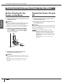 8
8
-
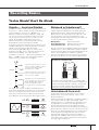 9
9
-
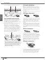 10
10
-
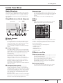 11
11
-
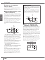 12
12
-
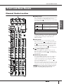 13
13
-
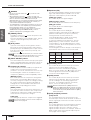 14
14
-
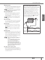 15
15
-
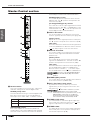 16
16
-
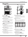 17
17
-
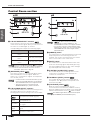 18
18
-
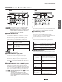 19
19
-
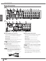 20
20
-
 21
21
-
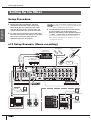 22
22
-
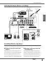 23
23
-
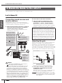 24
24
-
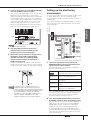 25
25
-
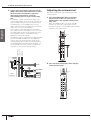 26
26
-
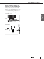 27
27
-
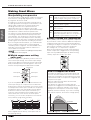 28
28
-
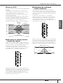 29
29
-
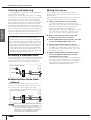 30
30
-
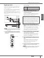 31
31
-
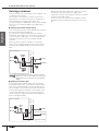 32
32
-
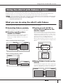 33
33
-
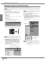 34
34
-
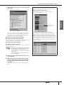 35
35
-
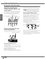 36
36
-
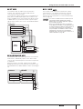 37
37
-
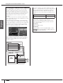 38
38
-
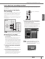 39
39
-
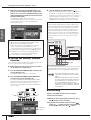 40
40
-
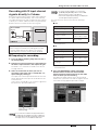 41
41
-
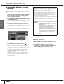 42
42
-
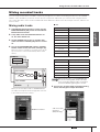 43
43
-
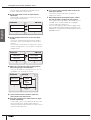 44
44
-
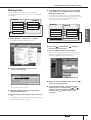 45
45
-
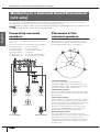 46
46
-
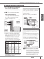 47
47
-
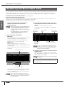 48
48
-
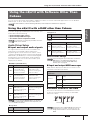 49
49
-
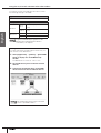 50
50
-
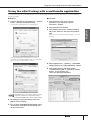 51
51
-
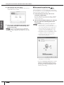 52
52
-
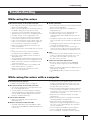 53
53
-
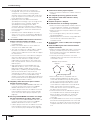 54
54
-
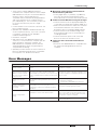 55
55
-
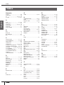 56
56
-
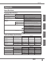 57
57
-
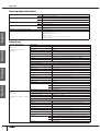 58
58
-
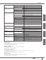 59
59
-
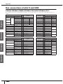 60
60
-
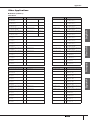 61
61
-
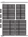 62
62
-
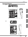 63
63
-
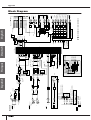 64
64
-
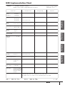 65
65
-
 66
66


Yamaha n12 El manual del propietario
- Categoría
- Equipo musical
- Tipo
- El manual del propietario
- Este manual también es adecuado para
en otros idiomas
- français: Yamaha n12 Le manuel du propriétaire
- italiano: Yamaha n12 Manuale del proprietario
- English: Yamaha n12 Owner's manual
- Deutsch: Yamaha n12 Bedienungsanleitung
- русский: Yamaha n12 Инструкция по применению
- Nederlands: Yamaha n12 de handleiding
- português: Yamaha n12 Manual do proprietário
- dansk: Yamaha n12 Brugervejledning
- polski: Yamaha n12 Instrukcja obsługi
- čeština: Yamaha n12 Návod k obsluze
- svenska: Yamaha n12 Bruksanvisning
- Türkçe: Yamaha n12 El kitabı
- suomi: Yamaha n12 Omistajan opas
- română: Yamaha n12 Manualul proprietarului
Artículos relacionados
-
Yamaha n12 Manual de usuario
-
-
-
Yamaha Version2 Guía de instalación
-
-
-
-
-
-
Otros documentos
-
Focusrite Platinum TwinTrak PRO El manual del propietario
-
Clarion 6610 Manual de usuario
-
Marantz PMD-706 Guía del usuario
-
LD Systems LD MIX G3 Serie Manual de usuario
-
Steinberg VST Connect Performer Manual de usuario
-
Peavey SMR 821a Manual de usuario
-
-
Sharp CP-LS100 High Performance Portable Speaker Manual de usuario
-
Work-pro KRONUS PRO 16700 Manual de usuario