Air King 3C614C Manual de usuario
- Categoría
- Ventiladores domésticos
- Tipo
- Manual de usuario
Este manual también es adecuado para

READ AND SAVE THESE INSTRUCTIONS
READ CAREFULLY BEFORE ATTEMPTING TO ASSEMBLE, INSTALL, OPERATE OR MAINTAIN THE PRODUCT DESCRIBED.
PROTECT YOURSELF AND OTHERS BY OBSERVING ALL SAFETY INFORMATION. FAILURE TO COMPLY WITH
INSTRUCTIONS COULD RESULT IN PERSONAL INJURY AND/OR PROPERTY DAMAGE!
RETAIN INSTRUCTIONS FOR FUTURE REFERENCE.
DESCRIPTION
The AirKing 20" (50.8 cm) Whole House Window Fan features three
intake and three exhaust speeds. Fan will fit windows 27" (68.6 cm) to
38" (96.5 cm) wide x 26-1/4" (67.3 cm) high. The adjustable side panels
are designed to accommodate Fan mounting either inside or outside
interior window trim. The 3-paddle Fan blade is driven by a permanently
pre-lubricated permanent split capacitor motor with 6' (1.8 m), 18/3 cord set.
SPECIFICATIONS
Motor ....................................... 120V, 50/60 Hz
Blade diameter ....................... 20" (50.8 cm)
Speeds .................................... 3 Intake, 3 Exhaust
Control .................................... Rotary Switch
Approvals ................................ UL Listed. Close mesh Fan guard
meets OSHA requirements.
20" WHOLE HOUSE WINDOW FAN
20" (50.8 cm) MODEL 3C614C/9166C
OPERATING INSTRUCTIONS & PARTS MANUAL
6. This Fan is intended for general use ONLY. It must NOT be used in
potentially dangerous locations such as flammable, explosive, chemi-
cal-laden or wet atmospheres.
WARNING: TO REDUCE THE RISK OF FIRE OR ELECTRIC SHOCK,
DO NOT USE THIS FAN WITH ANY SOLID STATE SPEED CONTROL
DEVICE.
MAINTENANCE
WARNING: ALWAYS UNPLUG THE CORD BEFORE SERVICING.
CLEANING: Use a soft cloth and a mild soap solution such as liquid dish
washing detergent.
CAUTION: Do not use gasoline, benzine, thinner, harsh cleaners,
etc. which will damage the Fan.
Dry all parts with a soft cloth completely before reconnecting to power supply.
STORAGE: When not in use, keep unit in a clean dry place.
MOTOR IS PERMANENTLY LUBRICATED.
ASSEMBLY AND INSTALLATION
PLEASE REMOVE CORRUGATED PACKING RING BETWEEN FAN
BLADE AND GRILL BEFORE INSTALLATION AND OPERATION OF
FAN.
The large number of window styles and types makes it impossible to
describe one universal installation procedure.
The methods outlined below are recommended as being well-suited for
most common styles of double-hung windows. Whichever method you
choose should allow the window to be closed easily for security and
protection of home furnishings against the weather. Refer to illustrations
while following METHOD A
(OUTSIDE of TRIM)
or METHOD B
(INSIDE
of TRIM)
below.
Tools Required: Screwdrivers
Hardware Provided: Four #8 x 3/4" Slotted Head Screws
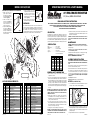
METHOD A
(OUTSIDE OF TRIM)
1. Loosen 4 Extender Panel Screws and extend Side Panels to clear the
outer edge of trim on each side of window.
(Figure 1)
Rev. D 1/00 1 2085109A
GENERAL SAFETY INFORMATION
1. Make certain that the power source conforms to the electrical
requirements of the Fan.
2. The power cord is equipped with a three-prong grounded plug that
must be inserted into a matching receptacle. Under no circumstances
must the grounding prong be cut off the plug. Where a two-prong wall
receptacle is encountered, it must be replaced with a properly grounded
three-prong receptacle installed in accordance with the National
Electrical Code (NEC) and all applicable local codes and ordinances.
This work must be done only by a qualified electrician, using copper
wire only.
WARNING: USE OF A THREE-PRONG TO TWO-PRONG ADAPTER IS
NOT RECOMMENDED. IMPROPER CONNECTION MAY CREATE
THE RISK OF ELECTROCUTION. USE OF SUCH ADAPTERS IS NOT
PERMITTED IN CANADA.
3. Where possible, avoid the use of extension cords. If they must be
used, minimize the risk of overheating by ensuring that they are UL
listed and of the proper gage and length. Never use a single extension
cord to operate more than one Fan.
4. Do not insert fingers or foreign objects into the Fan. Do not block or
tamper with the Fan in any manner while it is in operation. Do not touch
the Fan while in operation or just after it has been turned off, as some
parts may be hot enough to cause injury.
5. Unplug power cord before installing or servicing the Fan.
WARNING: DO NOT DEPEND UPON THE ON-OFF SWITCH AS THE
SOLE MEANS OF DISCONNECTING POWER WHEN INSTALLING OR
SERVICING THE FAN. ALWAYS UNPLUG THE POWER CORD.
Figure 1
MODEL
3C614C/9166C
SPEED
HIGH MED LOW
CFM 7005 6165 4160
M
3
/s 3.31 2.91 1.96
RPM 834 700 520
Amps 3.20 2.40 1.80
Watts 364 280 185
dB A 64 59 50
Slots
Flange
Extender
Panel
Screws
2. Rest Fan on window sill with Flange on Side Panels over trim. Push in
Side Panels tight against outer edge of trim. With Side Panel in position,
mark Screw locations at top of Slot and drive in the Wood Screws
(provided) until tight.
3. Retighten Extender Panel Screws to complete installation.
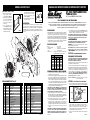
MODELO 3C614C/9166C
LISTA DE PIEZAS DE REPUESTO
No. Parte No. Descripción Cant.
Figura 3
1 2070024G Emblema AirKing 1
2 2010208 Protector del Ornamento 1
3 2096151 Rejilla Interior 1
4 2091121 Tornillo Prisionero 1
5 2011219 Hélice 1
6 2030073A Conjunto del Motor 1
7 3091118 Arandela #8 8
8 2091413 Tornillo para Madera #8 x 3/4" 4
9 2060085 Paneles Laterales 2
10 2090039 Tornillo #8 x 3/8" (Tipo 25) 4
11 2010720 Cuerpo del Ventilador con Canales 1
12 2011224 Rejilla Exterior 1
13 2090548 Atadura para Cable #10 1
14 3091135 Tornillo #10 x 1/2" 1
15 2090289 Capacitor 1
16 2011225 Cubierta del Motor 1
17 2090008 Tornillo #8 x 1/2" (Tipo 25) 5
18 3091815 Conector Eléctrico 4
MÉTODO B
(POR ADENTRO DE LAS MOLDURAS)
1. Marque la posición de los
agujeros para los Tornillos en
los bordes interiores del marco
de la ventana utilizando el Patrón
suministrado.
(Figura 2)
2. Instale los 4 Tornillos en el
marco. NO LOS APRIETE DEL
TODO. Deje 1/8" (3,2 mm) entre
la superficie del marco y la
Cabeza de los Tornillos.
3. Afloje los 4 Tornillos para Paneles
de Extensión
(Figura 1)
y
extienda los Paneles Laterales
hasta que el Ventilador quede
bien ajustado entre los lados del
marco de la ventana.
4. Instale el Ventilador en la ventana
enganchando las Ranuras en los Tornillos
en el marco de la ventana. Deslice el
Ventilador hacia abajo en los Tornillos
hasta que descanse sobre la parte inferior
del marco.
(Figura 3)
5. Apriete los Tornillos para Paneles de
Extensión para asegurario en esa posición.
OPERACIÓN
Este Ventilador AirKing para Toda la Casa tiene un duradero motor
eléctrico reversible de 3 velocidades con arranque por capacitor. Tiene
tres velocidades: Alta (Hi), Media (Medium) y Baja (Low) tanto para uso
de Ventilador como de extactor. El interuptor de control está
convenientemente ubicado en la parte inferior derecha del cuerpo del
Ventilador. Ajuste la Perilla a la dirección y Velocidad deseadas.
Figura 2
Ranura
Tornillo
1/8" (3,2 mm)
No. Parte No. Descripción Cant.
PLANTILLA
Rev. D 1/00 4 2085109A
1
2
3
4
5
6
8
9
7
10
11
12
13
14
15
16
18
19
7
17
20
21
22
23
9
8
24
25
26
28
27
31
32
33
34
35
36
10
10
10
17
22
23
26
18
29
30
33
36
36
19 7092211 Tuerca Hexagonal #8 - 32 4
20 2010744 Cubierta del Interruptor 1
21 2055052 Interruptor Reversible de 3 Velocidades 1
22 2091133 Tuerca Hexagonal 1/4" - 20 4
23 2090053 Arandela de Presión 1/4" 4
24 2090566 Atadura para Cables 2
25 2090044 Tornillo 6 - 32 x 1/4" 1
26 2090509 Canal de Goma 4
27 3091303W Buje para el Alambre 1
28 2050009AW Cable de Alimentación 1
29 2046101 Alambre de Conducir Verde 1
30 2046922 Alambre de Conducir Azul 1
31 2084071 Plantilla 1
32 2065228A Placa del Interruptor 1
33 2091130 Tornillo 1/4" - 20 x 1" 4
34 2010745 Perilla del Interruptor 1
35 2090547 Tuerca de Lámina 3
36 2090062 Tornillo #8 x 1/2" (Punta A) 6

Rev. D 1/00 2 2085109A
MODEL 3C614C/9166C
REPLACEMENT PARTS LIST
Key Part No. Description Qty.
Figure 3
LEA Y GUARDE ESTAS INSTRUCCIONES
LÉALAS CUIDADOSAMENTE ANTES DE INTENTAR ARMAR, INSTALAR, OPERAR O DAR MANTENIMIENTO AL PRODUCTO
DESCRITO. PROTÉJASE A SÍ MISMO Y A LOS DEMÁS OBSERVANDO TODA LA INFORMACIÓN SOBRE SEGURIDAD. ¡NO
SEGUIR LAS INSTRUCCIONES PODRÍA RESULTAR EN LESIONES PERSONALES Y/O DAÑOS A LA PROPIEDAD!
GUARDE LAS INSTRUCCIONES PARA REFERENCIAS FUTURAS.
DESCRIPCIÓN
El Ventilador AirKing 20" (50,8 cm) para Toda la Casa tiene tres velocidades
de ventilación y tres de extracción. El Ventilador puede instalarse en
ventanas desde 27" (68,6 cm) hasta 38" (96,5 cm) de ancho por 26-1/4"
(66,7 cm) de altura. Los paneles laterales ajustables están diseñados para
acomadarse a la instalación del Ventilador por adentro o por afuera de las
molduras interiores de la ventana. La hélice de tres aspas del Ventilador
está accionada por un motor de arranque con capacitor, prelubricado y
con cable de 6 pies (1,8 m) de tres conductores calibre 18.
ESPECIFICACIONES
Motor ............................................... 120V, 50/60Hz
Tarmano De Paletas ...................... 20" (50,8 cm)
Velocidades .................................... 3 de Extracción, 3 de Ventilación
Control ............................................ Conjuntor rotatorio
Aprobaciones ..............Catalogación UL. El protector de malla cerrada
del ventilador satisface las normas OSHA.
MANUAL DE INSTRUCCIONES DE OPERACIÓN Y PARTES
6. Este ventilador es para uso general EXCLUSIVAMENTE. NO deberá
usarse en localidades potencialmente peligrosas tales como atmósferas
inflamables, explosivas, cargadas de gases o húmedas.
ADVERTENCIA: PARA REDUCIR EL RIESGO DE INCENDIOS O
DESCARGAS ELÉCTRICAS, NO USE ESTE VENTILADOR CON NINGÚN
DISPOSITIVO DE CONTROL DE VELOCIDAD DE ESTADO SÓLIDO.
MANTENIMIENTO
ADVERTENCIA: DESCONECTE SIEMPRE EL CORDÓN ANTES DE
INTENTAR REALIZAR CUALQUIER FUNCIÓN DE SERVICIO.
LIMPIEZA: Use un trapo y una solución de jabón suave, tal como
detergente líquido para lavar trastes.
ADVERTENCIA: No use gasolina, bencina, diluyente de pintura ni
limpiadores fuertes en aerosol, ya que éstos dañarán el Ventilador.
ALMACENAMIENTO: Cuando no lo utilice, mantenga el aparato en un
lugar limpio y seco.
EL MOTOR HA SIDO PERMANENTEMENTE LUBRICADO.
ENSAMBLE Y INSTALACIÓN
POR FAVOR QUITE EL ANILLO CORRUGADO DE EMPAQUE QUE
ESTÁ ENTRE LA PALETA Y LA REJILLA, ANTES DE HACER LA
INSTALACIÓN Y PONERLO A FUNCIONAR.
El gran número de estilos y tipo de ventanas hace imposible describir un
procedimiento de instalación universal.
Los métodos que se detallan a continuación se recomiendan como aptos
para la mayoria de las ventanas de dos paneles que se deslizan verticalmente.
Cualquiera que sea el método que usted elija, deberá permitir que la
ventana se cierre con facilidad para su seguridad y para la protección de
los enseres domésticos contra el mal tiempo. Consulte las ilustraciones
mientras utiliza el MÉTODO A
(POR AFUERA DE LAS MOLDURAS)
o
el MÉTODO B
(POR ADENTRO DE LAS MOLDURAS)
a continuación.
Herramientas Requeridas: Destornillador
Elementos Suministrados: Cuatro Tornillos #8 x 3/4" con Ranura
para Destornillador Plano
MÉTODO A
(POR AFUERA DE LAS MOLDURAS)
1. Afloje los 4 Tornillos para Paneles de Extensión y extienda los Paneles
Laterales, pero que el Ventilador aún quepa en la ventana.
(Figura 1)
20" (50,8) VENTILADOR PARA
TODA LA CASA
20" (50,8 cm) MODELO 3C614C/9166C
INFORMACIÓN GENERAL SOBRE SEGURIDAD
1. Cerciórese de que la fuente de electricidad se adapte a los
requerimientos eléctricos del ventilador.
2. El cordón eléctrico está equipado con una clavija a tierra de tres espigas
que tiene que ser enchufada a un receptáculo del mismo diseño. Bajo
ninguna circunstancia deberá cortarse la espiga a tierra de la clavija. De
existir un receptáculo de pared de dos espigas, deberá reemplazarse
por uno de tres espigas debidamente puesto a tierra e instalado de
conformidad con el Código Nacional de Electricidad y todos los códigos
y ordenanzas locales aplicables. El trabajo deberá hacerlo un electricista
calificado, utilizando exclusivamente alambre de cobre.
ADVERTENCIA: NO SE RECOMIENDA EL USO DE UN ADAPTADOR
DE TRES A DOS ESPIGAS. LA CONEXIÓN INDEBIDA PODRÍA CREAR
EL RIESGO DE SER ELECTROCUTADO. EL USO DE TALES
ADAPTADORES NO ESTÁ PERMITIDO EN CANADÁ.
3. Siempre que sea posible, evite el uso de extensiones eléctricas. Si tienen
que usarse, minimice el riesgo de sobrecalentamiento asegurándose de
que sean de catalogación UL y del calibre y la longitud adecuadas. Nunca
use una sola extensión para operar más de un ventilador.
4. No introduzca los dedos ni objetos extraños en el ventilador. No
obstruya ni manipule indebidamente el ventilador mientras esté en
operación. No toque el ventilador mientras esté en operación ni
inmediatamente después de haberlo apagado, ya que ciertas partes
podrían estar lo suficientemente calientes como para causar una lesión.
5. Desenchufe el cordón eléctrico antes de instalar o dar servicio al
ventilador.
ADVERTENCIA: NO DEPENDA DEL INTERRUPTOR DE ENCENDIDO
Y APAGADO COMO EL ÚNICO MEDIO PARA INTERRUMPIR LA
ALIMENTACIÓN ELÉCTRICA CUANDO INSTALE O DÉ SERVICIO AL
VENTILADOR. SIEMPRE DESENCHUFE EL CORDÓN ELÉCTRICO.
MODELO
3C614C/9166C
VELOC.
ALTA MEDIA BAJA
CFM 7005 6165 4160
M
3
/s 3.31 2.91 1.96
RPM 834 700 520
Amps 3.20 2.40 1.80
Watts 364 280 185
dB A 64 59 50
1 2070024G Bullseye AirKing 1
2 2010208 Guard Ornament 1
3 2096151 Inside Guard 1
4 2091121 Set Screw 1
5 2011219 Blade 1
6 2030073A Motor Assembly 1
7 3091118 #8 Washer 8
8 2091413 #8 x 3/4" Wood Screw 4
9 2060085 Side Panels 2
10 2090039 #8 x 3/8" Screw (Type 25) 4
11 2010720 Fan Body w/Channels 1
12 2011224 Outside Guard 1
13 2090548 Wire Tie #10 Stud 1
14 3091135 #10 x 1/2" Screw 1
15 2090289 Capacitor 1
16 2011225 Motor Cover 1
17 2090008 #8 x 1/2" Screw (Type 25) 5
18 3091815 Wire Nut 4
METHOD B
(INSIDE OF TRIM)
1. Mark Screw locations on inside
edges of window trim using
enclosed Template.
(Figure 2)
2. Drive 4 Wood Screws (provided)
into trim. DO NOT TIGHTEN
FLUSH. Leave 1/8" space
between Screw Heads and
window trim.
3. Loosen 4 Extender Panel
Screws
(Figure 1)
and extend
Panels on each side of Housing
until the Fan fits snugly between
right and left window trim.
4. Mount Fan in window by engaging Slots
with installed Wood Screws on inside
edge of trim. Lower Fan onto 4 Screws
until it rests on window sill or sash
moulding.
(Figure 3)
5. Retighten Extender Panel Screws to
secure Fan in position.
OPERATION
This AirKing Whole House Window Fan is powered by a durable,
electrically reversible, 3-speed permanent split capacitor motor. (High,
Medium and Low speed settings are available for both INTAKE and
EXHAUST mode.) The Control Switch is conveniently located on the
lower right hand side of the Fan Body. Adjust Knob direction and Speed
desired.
Figure 2
Slot
Screw
1/8" (3.2 mm)
Key Part No. Description Qty.
1
2
3
4
5
6
8
9
7
10
11
12
13
14
15
16
18
19
7
17
20
21
22
23
9
8
24
25
26
28
27
31
32
33
34
35
36
Figura 1
Ranura
Brida
Tornillo para
Paneles de
Extensión
2. Coloque el Ventilador en el marco de la ventana con la Brida de los
Paneles Laterales sobre la moldura de la ventana. Presione los
Paneles Laterales hasta que queden bien ajustados contra las
molduras. Con Paneles Laterales en esta posición, marque los
agujeros para los Tornillos en la parte superior de las Ranuras, instale
4 Tornillos para Madera (provistos) y apriételos.
3. Apriete los Tornillos para Paneles de Extensión para completar la
instalación.
10
10
10
17
22
23
26
18
29
30
33
36
36
19 7092211 #8 - 32 Hex Nut 4
20 2010744 Switch Cover 1
21 2055052 3-Speed Reverse Switch 1
22 2091133 1/4" - 20 Hex Nut 4
23 2090053 1/4" Lockwasher 4
24 2090566 Wire Tie 2
25 2090044 6 - 32 x 1/4" Screw 1
26 2090509 Rubber Channel 4
27 3091303W Strain Relief 1
28 2050009AW Cordset 1
29 2046101 Lead Wire Green 1
30 2046922 Lead Wire Blue 1
31 2084071 Template 1
32 2065228A Switch Plate 1
33 2091130 1/4" - 20 x 1" Screw 4
34 2010745 Switch Knob 1
35 2090547 Palnut 3
36 2090062 #8 x 1/2" Screw (A Point) 6
Rev. D 1/00 3 2085109A
Transcripción de documentos
MODELO 3C614C/9166C 4. Instale el Ventilador en la ventana enganchando las Ranuras en los Tornillos en el marco de la ventana. Deslice el Ventilador hacia abajo en los Tornillos hasta que descanse sobre la parte inferior del marco. (Figura 3) 5. Apriete los Tornillos para Paneles de Extensión para asegurario en esa posición. MÉTODO B (POR ADENTRO DE LAS MOLDURAS) 1. Marque la posición de los agujeros para los Tornillos en los bordes interiores del marco de la ventana utilizando el Patrón suministrado. (Figura 2) 2. Instale los 4 Tornillos en el marco. NO LOS APRIETE DEL TODO. Deje 1/8" (3,2 mm) entre la superficie del marco y la Cabeza de los Tornillos. 3. Afloje los 4 Tornillos para Paneles de Extensión (Figura 1) y extienda los Paneles Laterales hasta que el Ventilador quede bien ajustado entre los lados del marco de la ventana. OPERATING INSTRUCTIONS & PARTS MANUAL PLANTILLA 1/8" (3,2 mm) 20" WHOLE HOUSE WINDOW FAN 20" (50.8 cm) MODEL 3C614C/9166C Figura 3 READ AND SAVE THESE INSTRUCTIONS OPERACIÓN Este Ventilador AirKing para Toda la Casa tiene un duradero motor eléctrico reversible de 3 velocidades con arranque por capacitor. Tiene tres velocidades: Alta (Hi), Media (Medium) y Baja (Low) tanto para uso de Ventilador como de extactor. El interuptor de control está convenientemente ubicado en la parte inferior derecha del cuerpo del Ventilador. Ajuste la Perilla a la dirección y Velocidad deseadas. Figura 2 14 12 10 8 Tornillo Ranura 17 16 23 22 18 7 20 3 26 10 4 22 24 10 21 MODEL 25 29 18 7 33 36 10 27 2 30 9 8 34 36 31 LISTA DE PIEZAS DE REPUESTO No. Parte No. Descripción 1 2 3 4 5 6 7 8 9 10 11 12 13 14 15 16 17 18 2070024G 2010208 2096151 2091121 2011219 2030073A 3091118 2091413 2060085 2090039 2010720 2011224 2090548 3091135 2090289 2011225 2090008 3091815 Emblema AirKing Protector del Ornamento Rejilla Interior Tornillo Prisionero Hélice Conjunto del Motor Arandela #8 Tornillo para Madera #8 x 3/4" Paneles Laterales Tornillo #8 x 3/8" (Tipo 25) Cuerpo del Ventilador con Canales Rejilla Exterior Atadura para Cable #10 Tornillo #10 x 1/2" Capacitor Cubierta del Motor Tornillo #8 x 1/2" (Tipo 25) Conector Eléctrico Rev. D 1/00 HIGH MED LOW CFM M3/s RPM Amps Watts dB A 7005 3.31 834 3.20 364 64 6165 2.91 700 2.40 280 59 4160 1.96 520 1.80 185 50 ASSEMBLY AND INSTALLATION PLEASE REMOVE CORRUGATED PACKING RING BETWEEN FAN BLADE AND GRILL BEFORE INSTALLATION AND OPERATION OF FAN. The large number of window styles and types makes it impossible to describe one universal installation procedure. The methods outlined below are recommended as being well-suited for most common styles of double-hung windows. Whichever method you choose should allow the window to be closed easily for security and protection of home furnishings against the weather. Refer to illustrations while following METHOD A (OUTSIDE of TRIM) or METHOD B (INSIDE of TRIM) below. Tools Required: Screwdrivers Hardware Provided: Four #8 x 3/4" Slotted Head Screws GENERAL SAFETY INFORMATION 35 36 3C614C/9166C SPEED 28 32 1 WARNING: ALWAYS UNPLUG THE CORD BEFORE SERVICING. CLEANING: Use a soft cloth and a mild soap solution such as liquid dish washing detergent. CAUTION: Do not use gasoline, benzine, thinner, harsh cleaners, etc. which will damage the Fan. Dry all parts with a soft cloth completely before reconnecting to power supply. STORAGE: When not in use, keep unit in a clean dry place. MOTOR IS PERMANENTLY LUBRICATED. 23 6 26 MAINTENANCE Motor ....................................... 120V, 50/60 Hz Blade diameter ....................... 20" (50.8 cm) Speeds .................................... 3 Intake, 3 Exhaust Control .................................... Rotary Switch Approvals ................................ UL Listed. Close mesh Fan guard meets OSHA requirements. 19 33 6. This Fan is intended for general use ONLY. It must NOT be used in potentially dangerous locations such as flammable, explosive, chemical-laden or wet atmospheres. WARNING: TO REDUCE THE RISK OF FIRE OR ELECTRIC SHOCK, DO NOT USE THIS FAN WITH ANY SOLID STATE SPEED CONTROL DEVICE. DESCRIPTION SPECIFICATIONS 17 5 RETAIN INSTRUCTIONS FOR FUTURE REFERENCE. The AirKing 20" (50.8 cm) Whole House Window Fan features three intake and three exhaust speeds. Fan will fit windows 27" (68.6 cm) to 38" (96.5 cm) wide x 26-1/4" (67.3 cm) high. The adjustable side panels are designed to accommodate Fan mounting either inside or outside interior window trim. The 3-paddle Fan blade is driven by a permanently pre-lubricated permanent split capacitor motor with 6' (1.8 m), 18/3 cord set. 13 11 9 15 READ CAREFULLY BEFORE ATTEMPTING TO ASSEMBLE, INSTALL, OPERATE OR MAINTAIN THE PRODUCT DESCRIBED. PROTECT YOURSELF AND OTHERS BY OBSERVING ALL SAFETY INFORMATION. FAILURE TO COMPLY WITH INSTRUCTIONS COULD RESULT IN PERSONAL INJURY AND/OR PROPERTY DAMAGE! Cant. No. Parte No. Descripción 1 1 1 1 1 1 8 4 2 4 1 1 1 1 1 1 5 4 19 20 21 22 23 24 25 26 27 28 29 30 31 32 33 34 35 36 7092211 2010744 2055052 2091133 2090053 2090566 2090044 2090509 3091303W 2050009AW 2046101 2046922 2084071 2065228A 2091130 2010745 2090547 2090062 Tuerca Hexagonal #8 - 32 Cubierta del Interruptor Interruptor Reversible de 3 Velocidades Tuerca Hexagonal 1/4" - 20 Arandela de Presión 1/4" Atadura para Cables Tornillo 6 - 32 x 1/4" Canal de Goma Buje para el Alambre Cable de Alimentación Alambre de Conducir Verde Alambre de Conducir Azul Plantilla Placa del Interruptor Tornillo 1/4" - 20 x 1" Perilla del Interruptor Tuerca de Lámina Tornillo #8 x 1/2" (Punta A) 4 Cant. 4 1 1 4 4 2 1 4 1 1 1 1 1 1 4 1 3 6 2085109A 1. Make certain that the power source conforms to the electrical requirements of the Fan. 2. The power cord is equipped with a three-prong grounded plug that must be inserted into a matching receptacle. Under no circumstances must the grounding prong be cut off the plug. Where a two-prong wall receptacle is encountered, it must be replaced with a properly grounded three-prong receptacle installed in accordance with the National Electrical Code (NEC) and all applicable local codes and ordinances. This work must be done only by a qualified electrician, using copper wire only. WARNING: USE OF A THREE-PRONG TO TWO-PRONG ADAPTER IS NOT RECOMMENDED. IMPROPER CONNECTION MAY CREATE THE RISK OF ELECTROCUTION. USE OF SUCH ADAPTERS IS NOT PERMITTED IN CANADA. 3. Where possible, avoid the use of extension cords. If they must be used, minimize the risk of overheating by ensuring that they are UL listed and of the proper gage and length. Never use a single extension cord to operate more than one Fan. 4. Do not insert fingers or foreign objects into the Fan. Do not block or tamper with the Fan in any manner while it is in operation. Do not touch the Fan while in operation or just after it has been turned off, as some parts may be hot enough to cause injury. 5. Unplug power cord before installing or servicing the Fan. WARNING: DO NOT DEPEND UPON THE ON-OFF SWITCH AS THE SOLE MEANS OF DISCONNECTING POWER WHEN INSTALLING OR SERVICING THE FAN. ALWAYS UNPLUG THE POWER CORD. Rev. D 1/00 METHOD A (OUTSIDE OF TRIM) 1. Loosen 4 Extender Panel Screws and extend Side Panels to clear the outer edge of trim on each side of window. (Figure 1) Slots Extender Panel Screws Flange Figure 1 2. Rest Fan on window sill with Flange on Side Panels over trim. Push in Side Panels tight against outer edge of trim. With Side Panel in position, mark Screw locations at top of Slot and drive in the Wood Screws (provided) until tight. 3. Retighten Extender Panel Screws to complete installation. 1 2085109A MANUAL DE INSTRUCCIONES DE OPERACIÓN Y PARTES MODEL 3C614C/9166C 4. Mount Fan in window by engaging Slots with installed Wood Screws on inside edge of trim. Lower Fan onto 4 Screws until it rests on window sill or sash moulding. (Figure 3) 5. Retighten Extender Panel Screws to secure Fan in position. METHOD B (INSIDE OF TRIM) 1. Mark Screw locations on inside edges of window trim using enclosed Template. (Figure 2) 2. Drive 4 Wood Screws (provided) into trim. DO NOT TIGHTEN FLUSH. Leave 1/8" space between Screw Heads and window trim. 3. Loosen 4 Extender Panel Screws (Figure 1) and extend Panels on each side of Housing until the Fan fits snugly between right and left window trim. 1/8" (3.2 mm) 20" (50,8 cm) MODELO 3C614C/9166C This AirKing Whole House Window Fan is powered by a durable, electrically reversible, 3-speed permanent split capacitor motor. (High, Medium and Low speed settings are available for both INTAKE and EXHAUST mode.) The Control Switch is conveniently located on the lower right hand side of the Fan Body. Adjust Knob direction and Speed desired. 16 17 14 15 12 13 Figure 2 11 23 9 22 18 17 20 3 26 10 4 22 24 10 El Ventilador AirKing 20" (50,8 cm) para Toda la Casa tiene tres velocidades de ventilación y tres de extracción. El Ventilador puede instalarse en ventanas desde 27" (68,6 cm) hasta 38" (96,5 cm) de ancho por 26-1/4" (66,7 cm) de altura. Los paneles laterales ajustables están diseñados para acomadarse a la instalación del Ventilador por adentro o por afuera de las molduras interiores de la ventana. La hélice de tres aspas del Ventilador está accionada por un motor de arranque con capacitor, prelubricado y con cable de 6 pies (1,8 m) de tres conductores calibre 18. 21 23 MODELO 6 25 26 29 18 7 33 36 10 27 2 32 30 9 8 36 31 REPLACEMENT PARTS LIST Key 1 2 3 4 5 6 7 8 9 10 11 12 13 14 15 16 17 18 Part No. Description 2070024G 2010208 2096151 2091121 2011219 2030073A 3091118 2091413 2060085 2090039 2010720 2011224 2090548 3091135 2090289 2011225 2090008 3091815 Bullseye AirKing Guard Ornament Inside Guard Set Screw Blade Motor Assembly #8 Washer #8 x 3/4" Wood Screw Side Panels #8 x 3/8" Screw (Type 25) Fan Body w/Channels Outside Guard Wire Tie #10 Stud #10 x 1/2" Screw Capacitor Motor Cover #8 x 1/2" Screw (Type 25) Wire Nut Rev. D 1/00 ADVERTENCIA: DESCONECTE SIEMPRE EL CORDÓN ANTES DE INTENTAR REALIZAR CUALQUIER FUNCIÓN DE SERVICIO. LIMPIEZA: Use un trapo y una solución de jabón suave, tal como detergente líquido para lavar trastes. ADVERTENCIA: No use gasolina, bencina, diluyente de pintura ni limpiadores fuertes en aerosol, ya que éstos dañarán el Ventilador. ALMACENAMIENTO: Cuando no lo utilice, mantenga el aparato en un lugar limpio y seco. EL MOTOR HA SIDO PERMANENTEMENTE LUBRICADO. 3C614C/9166C VELOC. ALTA MEDIA BAJA CFM M3/s RPM Amps Watts dB A 7005 3.31 834 3.20 364 64 6165 2.91 700 2.40 280 59 4160 1.96 520 1.80 185 50 ENSAMBLE Y INSTALACIÓN POR FAVOR QUITE EL ANILLO CORRUGADO DE EMPAQUE QUE ESTÁ ENTRE LA PALETA Y LA REJILLA, ANTES DE HACER LA INSTALACIÓN Y PONERLO A FUNCIONAR. El gran número de estilos y tipo de ventanas hace imposible describir un procedimiento de instalación universal. Los métodos que se detallan a continuación se recomiendan como aptos para la mayoria de las ventanas de dos paneles que se deslizan verticalmente. Cualquiera que sea el método que usted elija, deberá permitir que la ventana se cierre con facilidad para su seguridad y para la protección de los enseres domésticos contra el mal tiempo. Consulte las ilustraciones mientras utiliza el MÉTODO A (POR AFUERA DE LAS MOLDURAS) o el MÉTODO B (POR ADENTRO DE LAS MOLDURAS) a continuación. Herramientas Requeridas: Destornillador Elementos Suministrados: Cuatro Tornillos #8 x 3/4" con Ranura para Destornillador Plano INFORMACIÓN GENERAL SOBRE SEGURIDAD 34 36 MANTENIMIENTO 28 35 1 6. Este ventilador es para uso general EXCLUSIVAMENTE. NO deberá usarse en localidades potencialmente peligrosas tales como atmósferas inflamables, explosivas, cargadas de gases o húmedas. ADVERTENCIA: PARA REDUCIR EL RIESGO DE INCENDIOS O DESCARGAS ELÉCTRICAS, NO USE ESTE VENTILADOR CON NINGÚN DISPOSITIVO DE CONTROL DE VELOCIDAD DE ESTADO SÓLIDO. DESCRIPCIÓN Motor ............................................... 120V, 50/60Hz Tarmano De Paletas ...................... 20" (50,8 cm) Velocidades .................................... 3 de Extracción, 3 de Ventilación Control ............................................ Conjuntor rotatorio Aprobaciones .............. Catalogación UL. El protector de malla cerrada del ventilador satisface las normas OSHA. 7 33 LÉALAS CUIDADOSAMENTE ANTES DE INTENTAR ARMAR, INSTALAR, OPERAR O DAR MANTENIMIENTO AL PRODUCTO DESCRITO. PROTÉJASE A SÍ MISMO Y A LOS DEMÁS OBSERVANDO TODA LA INFORMACIÓN SOBRE SEGURIDAD. ¡NO SEGUIR LAS INSTRUCCIONES PODRÍA RESULTAR EN LESIONES PERSONALES Y/O DAÑOS A LA PROPIEDAD! GUARDE LAS INSTRUCCIONES PARA REFERENCIAS FUTURAS. ESPECIFICACIONES 19 5 LEA Y GUARDE ESTAS INSTRUCCIONES Figure 3 OPERATION 10 8 20" (50,8) VENTILADOR PARA TODA LA CASA Screw Slot Qty. Key 1 1 1 1 1 1 8 4 2 4 1 1 1 1 1 1 5 4 19 20 21 22 23 24 25 26 27 28 29 30 31 32 33 34 35 36 2 Part No. Description 7092211 2010744 2055052 2091133 2090053 2090566 2090044 2090509 3091303W 2050009AW 2046101 2046922 2084071 2065228A 2091130 2010745 2090547 2090062 #8 - 32 Hex Nut Switch Cover 3-Speed Reverse Switch 1/4" - 20 Hex Nut 1/4" Lockwasher Wire Tie 6 - 32 x 1/4" Screw Rubber Channel Strain Relief Cordset Lead Wire Green Lead Wire Blue Template Switch Plate 1/4" - 20 x 1" Screw Switch Knob Palnut #8 x 1/2" Screw (A Point) Qty. 4 1 1 4 4 2 1 4 1 1 1 1 1 1 4 1 3 6 2085109A 1. Cerciórese de que la fuente de electricidad se adapte a los requerimientos eléctricos del ventilador. 2. El cordón eléctrico está equipado con una clavija a tierra de tres espigas que tiene que ser enchufada a un receptáculo del mismo diseño. Bajo ninguna circunstancia deberá cortarse la espiga a tierra de la clavija. De existir un receptáculo de pared de dos espigas, deberá reemplazarse por uno de tres espigas debidamente puesto a tierra e instalado de conformidad con el Código Nacional de Electricidad y todos los códigos y ordenanzas locales aplicables. El trabajo deberá hacerlo un electricista calificado, utilizando exclusivamente alambre de cobre. ADVERTENCIA: NO SE RECOMIENDA EL USO DE UN ADAPTADOR DE TRES A DOS ESPIGAS. LA CONEXIÓN INDEBIDA PODRÍA CREAR EL RIESGO DE SER ELECTROCUTADO. EL USO DE TALES ADAPTADORES NO ESTÁ PERMITIDO EN CANADÁ. 3. Siempre que sea posible, evite el uso de extensiones eléctricas. Si tienen que usarse, minimice el riesgo de sobrecalentamiento asegurándose de que sean de catalogación UL y del calibre y la longitud adecuadas. Nunca use una sola extensión para operar más de un ventilador. 4. No introduzca los dedos ni objetos extraños en el ventilador. No obstruya ni manipule indebidamente el ventilador mientras esté en operación. No toque el ventilador mientras esté en operación ni inmediatamente después de haberlo apagado, ya que ciertas partes podrían estar lo suficientemente calientes como para causar una lesión. 5. Desenchufe el cordón eléctrico antes de instalar o dar servicio al ventilador. ADVERTENCIA: NO DEPENDA DEL INTERRUPTOR DE ENCENDIDO Y APAGADO COMO EL ÚNICO MEDIO PARA INTERRUMPIR LA ALIMENTACIÓN ELÉCTRICA CUANDO INSTALE O DÉ SERVICIO AL VENTILADOR. SIEMPRE DESENCHUFE EL CORDÓN ELÉCTRICO. Rev. D 1/00 MÉTODO A (POR AFUERA DE LAS MOLDURAS) 1. Afloje los 4 Tornillos para Paneles de Extensión y extienda los Paneles Laterales, pero que el Ventilador aún quepa en la ventana. (Figura 1) Ranura Tornillo para Paneles de Extensión Brida Figura 1 2. Coloque el Ventilador en el marco de la ventana con la Brida de los Paneles Laterales sobre la moldura de la ventana. Presione los Paneles Laterales hasta que queden bien ajustados contra las molduras. Con Paneles Laterales en esta posición, marque los agujeros para los Tornillos en la parte superior de las Ranuras, instale 4 Tornillos para Madera (provistos) y apriételos. 3. Apriete los Tornillos para Paneles de Extensión para completar la instalación. 3 2085109A-
 1
1
-
 2
2


Air King 3C614C Manual de usuario
- Categoría
- Ventiladores domésticos
- Tipo
- Manual de usuario
- Este manual también es adecuado para
en otros idiomas
- English: Air King 3C614C User manual
Artículos relacionados
-
Air King 3C614D/9166D Manual de usuario
-
-
-
-
-
-
-
-