Air King 9154K Manual de usuario
- Categoría
- Altavoces de la barra de sonido
- Tipo
- Manual de usuario
Este manual también es adecuado para

4
MODELO 4C523K/9154K
2084020A Rev. F 9/00
11
22
14-
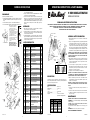
ENSAMBLAJE
(Ilustración para Ensamble - Pagina 1)
1. Alinea la REJILLA TRASERA con el pasador localizado en la TAPA
DE PLASTICO DEL MOTOR. Dejando los dos agujeros del centro asi
abajo.
2. Asiente la REJILLA y sujetela con la TUERCA DE PLÁSTICO.
3. Para evitar lastimar el HELICE, instalela empujando firmemente en el
centro hacia el EJE del MOTOR.
4. Coloque el GANCHO en la REJILLA DELANTERA sobre el alambre
central superior en la REJILLA TRASERA.
5. Torciendo suavemente quitar del sujetador los GANCHOS de la
REJILLA y colocarlos uniformemente alrededor del ventilador. Fijar
los GANCHOS en la REJILLA. Hacer que la cola del gancho agarre un
alambre redondo de la REJILLA TRASERA. Hacer que el cuerpo del
gancho agarre los bordes planos de ambas rejillas.
(Figura a y b
pagina 1)
OPERACIÓN
1. VELOCIDAD: Las velocidades se controlan mediante el conjuntor
rotatorio localizado en la base del ventilador.
2. OSCILACIÓN: Para hacer oscilar el ventilador, oprima el botón que se
encuentra sobre la cubierta del motor. Para que el ventilador deje de
oscilar, tire del botón hacia afuera.
3. AJUSTE DEL ÁNGULO: Se puede cambiar el ángulo del conjunto
superior del ventilador, aflojando primero el tornillo de elevación. Coloque
el conjunto superior en el ángulo deseado y fíjelo en posición volviendo
a apretar el tornillo de elevación.
LISTA DE REPUESTOS
Ref. No. de Parte Descripción Cant.
a) Jalé el boton de oscilacion asi
arriba para desenganchar el
mecanismo de oscilacion.
b) Usé un objecto como un mango
de un destornillador y
gentilmente pegé un golpecito
a la parte delantera de la helice.
No golpear el eje de la helice
asi adentro del motor.
c) Delé vuelta a la helice con la
mano. Si la helice no davuelta
libremente, sigá el paso
posterior hasta que la helice
gire libre.
PRECAUCION: De ninguna
manera prenda su ventilador sin
las revillas y asegurese que
ambas esten bien aseguradas.
TAP
HUB
SPIN
UP
1
2
3
a
b
c
GIRAR
ARRIBA
Centro
EJE
GOLPEAR
LIGERAMENTE
EJE
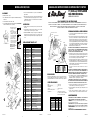
SPECIFICATIONS
Motor ................................................ 120V, 60 Hz
Blade diameter ................................ 9" (22.9 cm)
Speeds ............................................. 2
Control ............................................. Rotary Switch
Air flow distribution .......................... 90°
Approvals ......................................... UL Listed. Close mesh fan
guard meets OSHA requirements.
R
READ AND SAVE THESE INSTRUCTIONS
READ CAREFULLY BEFORE ATTEMPTING TO ASSEMBLE, INSTALL, OPERATE OR MAINTAIN THE PRODUCT DESCRIBED.
PROTECT YOURSELF AND OTHERS BY OBSERVING ALL SAFETY INFORMATION. FAILURE TO COMPLY WITH
INSTRUCTIONS COULD RESULT IN PERSONAL INJURY AND/OR PROPERTY DAMAGE!
RETAIN INSTRUCTIONS FOR FUTURE REFERENCE.
DESCRIPTION
The AirKing 9" (22.9 cm) oscillating fan features whisper-quiet perfor-
mance with a 3-paddle fan blade. The fan has a permanently lubricated
motor with a 6 ft (1.8 m) 18/3 cord set.
1
2084020A
9 INCH OSCILLATING FAN
MODEL 4C523K/9154K
BLADE
MOTOR
PLASTIC
NUT
REAR GRILL
FRONT
GRILL
GRILL CLIP
HOLDER
PLASTIC GRILL
CLIPS
.
HOOK
OSCILLATION CONTROL
ELEVATION
SCREW
SWITCH KNOB
a. b.
OPERATING INSTRUCTIONS & PARTS MANUAL
MODEL 4C523K/9154K
SPEED HIGH LOW
CFM 1205 906
M
3
/s .57 .43
RPM 2175 1644
Amps .55 .32
Watts 32 22
dB A 41 34
GENERAL SAFETY INFORMATION
1. Make certain that the power source conforms to the electrical require-
ments of the fan.
2. The power cord is equipped with a three-prong grounded plug that must
be inserted into a matching receptacle. Under no circumstances must
the grounding prong be cut off the plug. Where a two-prong wall
receptacle is encountered, it must be replaced with a properly grounded
three-prong receptacle installed in accordance with the National Elec-
trical Code (NEC) and all applicable local codes and ordinances. This
work must be done only by a qualified electrician, using copper wire only.
WARNING: USE OF A THREE-PRONG TO TWO-PRONG ADAPTER IS
NOT RECOMMENDED. IMPROPER CONNECTION MAY CREATE
THE RISK OF ELECTROCUTION. USE OF SUCH ADAPTERS IS NOT
PERMITTED IN CANADA.
3. Where possible, avoid the use of extension cords. If they must be used,
minimize the risk of overheating by ensuring that they are UL listed and
of the proper gauge and length. Never use a single extension cord to
operate more than one fan.
4. Do not insert fingers or foreign objects into the fan. Do not block or
tamper with the fan in any manner while it is in operation. Do not touch
the fan while in operation or just after it has been turned off, as some
parts may be hot enough to cause injury.
5. Unplug power cord before installing or servicing the fan.
WARNING: DO NOT DEPEND UPON THE ON-OFF SWITCH AS THE
SOLE MEANS OF DISCONNECTING POWER WHEN INSTALLING OR
SERVICING THE FAN. ALWAYS UNPLUG THE POWER CORD.
6. This fan is intended for general use ONLY. It must NOT be used in
potentially dangerous locations such as flammable, explosive, chemi-
cal-laden or wet atmospheres.
WARNING: TO REDUCE THE RISK OF FIRE OR ELECTRIC SHOCK,
DO NOT USE THIS FAN WITH ANY SOLID STATE SPEED CONTROL
DEVICE.
7. Be sure fan is on a stable surface when operating, to avoid chance of it
overturning.
8. DO NOT use fan in a window. Rain may create an electrical hazard.
9. Completely reassemble fan, according to instructions before reconnect-
ing to power supply.
MAINTENANCE
WARNING: ALWAYS UNPLUG THE CORD BEFORE SERVICING.
CLEANING: Use a soft cloth and a mild soap solution such as liquid dish
washing detergent.
CAUTION: Do not use gasoline, benzine, thinner, harsh cleaners,
etc. which will damage the fan.
Dry all parts with a soft cloth completely before reconnecting to power
supply.
STORAGE: When not in use, keep unit in a clean dry place.
MOTOR IS PERMANENTLY LUBRICATED.
Rev. F 9/00
1 2050009AW Cordón Eléctrico 1
2 2096045 Rejilla Delantera 1
3 2010004 Hélice 1
4 2010350 Tuerca de Plástico 1
5 2096050 Rejilla Trasera 1
6 2030056G Motor 1
7 2010619 Cubierta del Motor 1
8 2010119 Botón de Oscilación 1
10 2010279 Enlace 1
11 2090068 Tornillo #6 x 1/2" LH/H.W.H. 1
12 2010260 Cuello 1
13 2091133 Tuerca Hexagonal de 1/4 x 20 1
14 2090529 Tuerca Para Alambre 1
15 2090199 Tornillo Phillips de 1/4 - 20 x 1"
PPH Tornillo de Elevación 1
16 2010104 Botón del Interruptor 1
17 2065412 Ornamento de la Base 1
18 2010524 Base 1
19 2057065 Conjuntor Rotatorio 1
20 2010281 Placa Inferior 1
21 2010403A Pata de Caucho (4 utilizadas) 4
22 2090038 Tornillo Phillips de Cabeza
Reforzada #8 x 9/16 PPH 2
23 2010354 Sujetador de Rejilla 5
24 2066506G Accesorio del Botón del
Interruptor 1
25 2010241A Ornamento del Rejilla 1
26 2070024G Ojo de Buey (AirKing) 1
27 2090073 Tornillo #6 x 1/2" AB 1
27

R
LEA Y GUARDE ESTAS INSTRUCCIONES
LÉALAS CUIDADOSAMENTE ANTES DE INTENTAR ARMAR, INSTALAR, OPERAR O DAR MANTENIMIENTO AL PRODUCTO
DESCRITO. PROTÉJASE A SÍ MISMO Y A LOS DEMÁS OBSERVANDO TODA LA INFORMACIÓN SOBRE SEGURIDAD. ¡NO
SEGUIR LAS INSTRUCCIONES PODRÍA RESULTAR EN LESIONES PERSONALES Y/O DAÑOS A LA PROPIEDAD!
GUARDE LAS INSTRUCCIONES PARA REFERENCIAS FUTURAS.
DESCRIPCIÓN
El ventilador oscilante AirKing de 9" (22.9 cm) es de operación silenciosa y
tiene una unidad giratoria de 3 paletas. El ventilador tiene un motor
permanentemente lubricado con un cordón eléctrico de 6 pies (1.8 m) 18/3.
3
MANUAL DE INSTRUCCIONES DE OPERACIÓN Y PARTES
MODELO 4C523K/9154K
9" (22.9 cm) VENTILADOR
MULTIDIRECCIONAL
2084020A
Rev. F 9/00
HELICE
MOTOR
TUERCA DE
PLÁSTICO
REJILLA TRASERA
REJILLA
DELANTERA
SOPORTE DE
SUJETADORES
SUJETADOR
DE REJILLA
.
GANCHO
CONTROL DE OSCILACIÓN
TORNILLO DE
ELEVACIÓN
BOTÓN DEL
INTERRUPTOR
a. b.
ESPECIFICACIONES
Motor .................................................. 120V, 60Hz
Tamaño de paletas ............................ 9" (22.9 cm)
Velocidades ....................................... 2
Control ............................................... Conjuntor rotatorio
Distribución del lujo de aire ................ 90°
Aprobaciones ..................................... Catalogación UL. El protector
de malla cerrada del ventilador
satisface las normas OSHA.
MODELO 4C523K/9154K
VELOCIDAD ALTA BAJA
CFM 1205 906
M
3
/s .57 .43
RPM 2175 1644
Amps .55 .32
Watts 32 22
dB A 41 34
INFORMACIÓN GENERAL SOBRE SEGURIDAD
1. Cerciórese de que la fuente de electricidad se adapte a los requerimientos
eléctricos del ventilador.
2. El cordón eléctrico está equipado con una clavija a tierra de tres espigas
que tiene que ser enchufada a un receptáculo del mismo diseño. Bajo
ninguna circunstancia deberá cortarse la espiga a tierra de la clavija. De
existir un receptáculo de pared de dos espigas, deberá reemplazarse por
uno de tres espigas debidamente puesto a tierra e instalado de conformidad
con el Código Nacional de Electricidad y todos los códigos y ordenanzas
locales aplicables. El trabajo deberá hacerlo un electricista calificado,
utilizando exclusivamente alambre de cobre.
ADVERTENCIA: NO SE RECOMIENDA EL USO DE UN ADAPTADOR DE
TRES A DOS ESPIGAS. LA CONEXIÓN INDEBIDA PODRÍA CREAR EL
RIESGO DE SER ELECTROCUTADO. EL USO DE TALES
ADAPTADORES NO ESTÁ PERMITIDO EN CANADÁ.
3. Siempre que sea posible, evite el uso de extensiones eléctricas. Si tienen
que usarse, minimice el riesgo de sobrecalentamiento asegurándose de
que sean de catalogación UL y del calibre y la longitud adecuadas. Nunca
use una sola extensión para operar más de un ventilador.
4. No introduzca los dedos ni objetos extraños en el ventilador. No obstruya
ni manipule indebidamente el ventilador mientras esté en operación. No
toque el ventilador mientras esté en operación ni inmediatamente después
de haberlo apagado, ya que ciertas partes podrían estar lo suficientemente
calientes como para causar una lesión.
5. Desenchufe el cordón eléctrico antes de instalar o dar servicio al
ventilador.
ADVERTENCIA: NO DEPENDA DEL INTERRUPTOR DE ENCENDIDO Y
APAGADO COMO EL ÚNICO MEDIO PARA INTERRUMPIR LA
ALIMENTACIÓN ELÉCTRICA CUANDO INSTALE O DÉ SERVICIO AL
VENTILADOR. SIEMPRE DESENCHUFE EL CORDÓN ELÉCTRICO.
6. Este ventilador es para uso general EXCLUSIVAMENTE. NO deberá
usarse en localidades potencialmente peligrosas tales como atmósferas
inflamables, explosivas, cargadas de gases o húmedas.
ADVERTENCIA: PARA REDUCIR EL RIESGO DE INCENDIOS O
DESCARGAS ELÉCTRICAS, NO USE ESTE VENTILADOR CON NINGÚN
DISPOSITIVO DE CONTROL DE VELOCIDAD DE ESTADO SÓLIDO.
7. Asegúrese de que el ventilador esté sobre una superficie estable al estar
en funcionamiento, para evitar toda riesgo de que se voltee.
8. NO utilice el ventilador en una ventana, ya que la lluvia podría crear un
peligro eléctrico.
9. Vuelva a armar completamente el ventilador, de acuerdo con las
instrucciones, antes de volver a conectarlo a la alimentación eléctrica.
MANTENIMIENTO
ADVERTENCIA: DESCONECTE SIEMPRE EL CORDÓN ANTES DE
INTENTAR REALIZAR CUALQUIER FUNCIÓN DE SERVICIO.
LIMPIEZA: Use un trapo y una solución de jabón suave, tal como
detergente líquido para lavar trastes.
ADVERTENCIA: No use gasolina, bencina, diluyente de pintura ni
limpiadores fuertes en aerosol, ya que éstos dañarán el ventilador.
ALMACENAMIENTO: Cuando no lo utilice, mantenga el aparato en un
lugar limpio y seco.
EL MOTOR HA SIDO PERMANENTEMENTE LUBRICADO.
1 2050009AW Cord Set 1
2 2096045 Front Grill 1
3 2010004 Blade 1
4 2010350 Plastic Nut 1
5 2096050 Rear Grill 1
6 2030056G Motor 1
7 2010619 Motor Cover 1
8 2010119 Oscillation Knob 1
10 2010279 Link 1
11 2090068 Screw #6 x 1/2" LH/H.W.H. 1
12 2010260 Neck 1
13 2091133 Hex Nut 1/4 x 20 1
14 2090529 Wire Nut A-O 1
15 2090199 Elevation Screw
1/4 - 20 x 1" PPH 1
16 2010104 Switch Knob 1
17 2065412 Stand Ornament 1
18 2010524 Stand 1
19 2057065 Rotary Switch 1
20 2010281 Bottom Plate 1
21 2010403A Rubber Foot (4 used) 4
22 2090038 Screw #8 x 9/16 PPH 2
23 2010354 Plastic Grill Clips 5
24 2066506G Switch Knob Insert 1
25 2010241A Grill Ornament 1
26 2070024G Bullseye (AirKing) 1
27 2090073 Screw #6 x 1/2" AB 1
REPLACEMENT PARTS LIST
ASSEMBLY
(Assembly Illustration - Page 1)
1. Place REAR GRILL on MOTOR. Align holes in REAR GRILL with pins
on MOTOR.
2. Fasten REAR GRILL with PLASTIC NUT.
3. To avoid damaging BLADE, install by pushing firmly in CENTER HUB,
onto MOTOR SHAFT. (Follow steps below)
11
2
14-
MODEL 4C523K/9154K
2084020A
4. Place HOOK on FRONT GRILL over top center wire on REAR GRILL.
Align GRILLS.
5. With a twist, gently remove GRILL CLIPS from HOLDER and position
evenly around fan. Attach clips by snapping tail of CLIP over round wire
on REAR GRILL. Snap body of CLIP around flat wires of both GRILLS.
(Figures a and b, Page 1)
OPERATION
1. SPEEDS: The speed is controlled by the rotary switch located on the
fan stand.
2. OSCILLATION: Push down on the knob on the motor cover to start fan
oscillation. Pull up on the knob to stop fan oscillation.
3. ANGLE ADJUSTMENT: The angle of the upper fan assembly may be
changed by first loosening the elevation screw. Position the upper
assembly to the desired angle and lock in place by retightening elevation
screw.
Key Part No. Description Qty.
22
a) Pull oscillating knob up to
disengage oscillating
mechanism.
b) Using a blunt object, such
as a screwdriver handle,
gently tap on the front of
the blade hub. DO NOT
tap blade hub straight
back into the motor.
c) Spin blade by hand. If
blade does not spin freely
repeat previous step until
blade does spin freely.
CAUTION: At no time
should you turn the fan on
without grills being
securely attached.
TAP
HUB
SPIN
UP
1
2
3
a
b
c
Center
HUB
Rev. F 9/00
27
Transcripción de documentos
MODELO 4C523K/9154K centro hacia el EJE del MOTOR. 4. Coloque el GANCHO en la REJILLA DELANTERA sobre el alambre central superior en la REJILLA TRASERA. 5. Torciendo suavemente quitar del sujetador los GANCHOS de la REJILLA y colocarlos uniformemente alrededor del ventilador. Fijar los GANCHOS en la REJILLA. Hacer que la cola del gancho agarre un alambre redondo de la REJILLA TRASERA. Hacer que el cuerpo del gancho agarre los bordes planos de ambas rejillas. (Figura a y b pagina 1) ENSAMBLAJE (Ilustración para Ensamble - Pagina 1) 1. Alinea la REJILLA TRASERA con el pasador localizado en la TAPA DE PLASTICO DEL MOTOR. Dejando los dos agujeros del centro asi abajo. 2. Asiente la REJILLA y sujetela con la TUERCA DE PLÁSTICO. 3. Para evitar lastimar el HELICE, instalela empujando firmemente en el Centro EJE a) Jalé el boton de oscilacion asi arriba para desenganchar el mecanismo de oscilacion. b) Usé un objecto como un mango de un destornillador y gentilmente pegé un golpecito a la parte delantera de la helice. No golpear el eje de la helice asi adentro del motor. c) Delé vuelta a la helice con la mano. Si la helice no davuelta libremente, sigá el paso posterior hasta que la helice gire libre. 1 a OPERACIÓN UP 1. VELOCIDAD: Las velocidades se controlan mediante el conjuntor rotatorio localizado en la base del ventilador. 2. OSCILACIÓN: Para hacer oscilar el ventilador, oprima el botón que se encuentra sobre la cubierta del motor. Para que el ventilador deje de oscilar, tire del botón hacia afuera. 3. AJUSTE DEL ÁNGULO: Se puede cambiar el ángulo del conjunto superior del ventilador, aflojando primero el tornillo de elevación. Coloque el conjunto superior en el ángulo deseado y fíjelo en posición volviendo a apretar el tornillo de elevación. ARRIBA 2 b OPERATING INSTRUCTIONS & PARTS MANUAL TAP HUB GOLPEAR LIGERAMENTE EJE 3 c R MODEL 4C523K/9154K READ AND SAVE THESE INSTRUCTIONS READ CAREFULLY BEFORE ATTEMPTING TO ASSEMBLE, INSTALL, OPERATE OR MAINTAIN THE PRODUCT DESCRIBED. PROTECT YOURSELF AND OTHERS BY OBSERVING ALL SAFETY INFORMATION. FAILURE TO COMPLY WITH INSTRUCTIONS COULD RESULT IN PERSONAL INJURY AND/OR PROPERTY DAMAGE! RETAIN INSTRUCTIONS FOR FUTURE REFERENCE. OSCILLATION CONTROL MOTOR 1. Make certain that the power source conforms to the electrical requirements of the fan. PLASTIC NUT BLADE GIRAR SPIN Ref. No. de Parte 22 11 27 14- Rev. F 9/00 Descripción Cant. HOOK FRONT GRILL 2. The power cord is equipped with a three-prong grounded plug that must be inserted into a matching receptacle. Under no circumstances must the grounding prong be cut off the plug. Where a two-prong wall receptacle is encountered, it must be replaced with a properly grounded three-prong receptacle installed in accordance with the National Electrical Code (NEC) and all applicable local codes and ordinances. This work must be done only by a qualified electrician, using copper wire only. 1 2050009AW Cordón Eléctrico 1 2 2096045 Rejilla Delantera 1 3 2010004 Hélice 1 4 2010350 Tuerca de Plástico 1 5 2096050 Rejilla Trasera 1 6 2030056G Motor 1 7 2010619 Cubierta del Motor 1 8 2010119 Botón de Oscilación 1 10 2010279 Enlace 1 11 2090068 Tornillo #6 x 1/2" LH/H.W.H. 1 12 2010260 Cuello 1 5. Unplug power cord before installing or servicing the fan. 13 2091133 Tuerca Hexagonal de 1/4 x 20 1 14 2090529 Tuerca Para Alambre 1 WARNING: DO NOT DEPEND UPON THE ON-OFF SWITCH AS THE SOLE MEANS OF DISCONNECTING POWER WHEN INSTALLING OR SERVICING THE FAN. ALWAYS UNPLUG THE POWER CORD. 15 2090199 Tornillo Phillips de 1/4 - 20 x 1" PPH Tornillo de Elevación 1 16 2010104 Botón del Interruptor 1 17 2065412 Ornamento de la Base 1 SPECIFICATIONS 18 2010524 Base 1 19 2057065 Conjuntor Rotatorio 1 20 2010281 Placa Inferior 1 21 2010403A Pata de Caucho (4 utilizadas) 4 22 2090038 Tornillo Phillips de Cabeza Reforzada #8 x 9/16 PPH Motor ................................................ 120V, 60 Hz Blade diameter ................................ 9" (22.9 cm) Speeds ............................................. 2 Control ............................................. Rotary Switch Air flow distribution .......................... 90° Approvals ......................................... UL Listed. Close mesh fan guard meets OSHA requirements. 2 23 2010354 Sujetador de Rejilla 5 24 2066506G Accesorio del Botón del Interruptor 1 25 2010241A Ornamento del Rejilla 1 26 2070024G Ojo de Buey (AirKing) 1 27 2090073 Tornillo #6 x 1/2" AB 1 2084020A 4 GENERAL SAFETY INFORMATION REAR GRILL LISTA DE REPUESTOS PRECAUCION: De ninguna manera prenda su ventilador sin las revillas y asegurese que ambas esten bien aseguradas. 9 INCH OSCILLATING FAN WARNING: USE OF A THREE-PRONG TO TWO-PRONG ADAPTER IS NOT RECOMMENDED. IMPROPER CONNECTION MAY CREATE THE RISK OF ELECTROCUTION. USE OF SUCH ADAPTERS IS NOT PERMITTED IN CANADA. SWITCH KNOB ELEVATION SCREW 3. Where possible, avoid the use of extension cords. If they must be used, minimize the risk of overheating by ensuring that they are UL listed and of the proper gauge and length. Never use a single extension cord to operate more than one fan. GRILL CLIP HOLDER PLASTIC GRILL CLIPS . a. 4. Do not insert fingers or foreign objects into the fan. Do not block or tamper with the fan in any manner while it is in operation. Do not touch the fan while in operation or just after it has been turned off, as some parts may be hot enough to cause injury. b. DESCRIPTION 6. This fan is intended for general use ONLY. It must NOT be used in potentially dangerous locations such as flammable, explosive, chemical-laden or wet atmospheres. The AirKing 9" (22.9 cm) oscillating fan features whisper-quiet performance with a 3-paddle fan blade. The fan has a permanently lubricated motor with a 6 ft (1.8 m) 18/3 cord set. MODEL SPEED CFM M3/s RPM Amps Watts dB A WARNING: TO REDUCE THE RISK OF FIRE OR ELECTRIC SHOCK, DO NOT USE THIS FAN WITH ANY SOLID STATE SPEED CONTROL DEVICE. 7. Be sure fan is on a stable surface when operating, to avoid chance of it overturning. 8. DO NOT use fan in a window. Rain may create an electrical hazard. 9. Completely reassemble fan, according to instructions before reconnecting to power supply. MAINTENANCE WARNING: ALWAYS UNPLUG THE CORD BEFORE SERVICING. CLEANING: Use a soft cloth and a mild soap solution such as liquid dish washing detergent. CAUTION: Do not use gasoline, benzine, thinner, harsh cleaners, etc. which will damage the fan. Dry all parts with a soft cloth completely before reconnecting to power supply. STORAGE: When not in use, keep unit in a clean dry place. MOTOR IS PERMANENTLY LUBRICATED. 4C523K/9154K HIGH LOW 1205 906 .57 .43 2175 1644 .55 .32 32 22 41 34 2084020A Rev. F 9/00 1 MANUAL DE INSTRUCCIONES DE OPERACIÓN Y PARTES MODEL 4C523K/9154K 9" (22.9 cm) VENTILADOR MULTIDIRECCIONAL R 4. Place HOOK on FRONT GRILL over top center wire on REAR GRILL. Align GRILLS. ASSEMBLY (Assembly Illustration - Page 1) 2. Fasten REAR GRILL with PLASTIC NUT. 3. To avoid damaging BLADE, install by pushing firmly in CENTER HUB, onto MOTOR SHAFT. (Follow steps below) Center HUB a) Pull oscillating knob up to disengage oscillating mechanism. b) Using a blunt object, such as a screwdriver handle, gently tap on the front of the blade hub. DO NOT tap blade hub straight back into the motor. c) Spin blade by hand. If blade does not spin freely repeat previous step until blade does spin freely. 1 a OPERATION 1. SPEEDS: The speed is controlled by the rotary switch located on the fan stand. 2. OSCILLATION: Push down on the knob on the motor cover to start fan oscillation. Pull up on the knob to stop fan oscillation. 3. ANGLE ADJUSTMENT: The angle of the upper fan assembly may be changed by first loosening the elevation screw. Position the upper assembly to the desired angle and lock in place by retightening elevation screw. UP 2 b MODELO 4C523K/9154K 5. With a twist, gently remove GRILL CLIPS from HOLDER and position evenly around fan. Attach clips by snapping tail of CLIP over round wire on REAR GRILL. Snap body of CLIP around flat wires of both GRILLS. (Figures a and b, Page 1) 1. Place REAR GRILL on MOTOR. Align holes in REAR GRILL with pins on MOTOR. TAP HUB LEA Y GUARDE ESTAS INSTRUCCIONES LÉALAS CUIDADOSAMENTE ANTES DE INTENTAR ARMAR, INSTALAR, OPERAR O DAR MANTENIMIENTO AL PRODUCTO DESCRITO. PROTÉJASE A SÍ MISMO Y A LOS DEMÁS OBSERVANDO TODA LA INFORMACIÓN SOBRE SEGURIDAD. ¡NO SEGUIR LAS INSTRUCCIONES PODRÍA RESULTAR EN LESIONES PERSONALES Y/O DAÑOS A LA PROPIEDAD! GUARDE LAS INSTRUCCIONES PARA REFERENCIAS FUTURAS. INFORMACIÓN GENERAL SOBRE SEGURIDAD CONTROL DE OSCILACIÓN MOTOR 1. Cerciórese de que la fuente de electricidad se adapte a los requerimientos eléctricos del ventilador. 2. El cordón eléctrico está equipado con una clavija a tierra de tres espigas que tiene que ser enchufada a un receptáculo del mismo diseño. Bajo ninguna circunstancia deberá cortarse la espiga a tierra de la clavija. De existir un receptáculo de pared de dos espigas, deberá reemplazarse por uno de tres espigas debidamente puesto a tierra e instalado de conformidad con el Código Nacional de Electricidad y todos los códigos y ordenanzas locales aplicables. El trabajo deberá hacerlo un electricista calificado, utilizando exclusivamente alambre de cobre. ADVERTENCIA: NO SE RECOMIENDA EL USO DE UN ADAPTADOR DE TRES A DOS ESPIGAS. LA CONEXIÓN INDEBIDA PODRÍA CREAR EL RIESGO DE SER ELECTROCUTADO. EL USO DE TALES ADAPTADORES NO ESTÁ PERMITIDO EN CANADÁ. 3. Siempre que sea posible, evite el uso de extensiones eléctricas. Si tienen que usarse, minimice el riesgo de sobrecalentamiento asegurándose de que sean de catalogación UL y del calibre y la longitud adecuadas. Nunca use una sola extensión para operar más de un ventilador. 4. No introduzca los dedos ni objetos extraños en el ventilador. No obstruya ni manipule indebidamente el ventilador mientras esté en operación. No toque el ventilador mientras esté en operación ni inmediatamente después de haberlo apagado, ya que ciertas partes podrían estar lo suficientemente calientes como para causar una lesión. 5. Desenchufe el cordón eléctrico antes de instalar o dar servicio al ventilador. ADVERTENCIA: NO DEPENDA DEL INTERRUPTOR DE ENCENDIDO Y APAGADO COMO EL ÚNICO MEDIO PARA INTERRUMPIR LA ALIMENTACIÓN ELÉCTRICA CUANDO INSTALE O DÉ SERVICIO AL VENTILADOR. SIEMPRE DESENCHUFE EL CORDÓN ELÉCTRICO. 6. Este ventilador es para uso general EXCLUSIVAMENTE. NO deberá usarse en localidades potencialmente peligrosas tales como atmósferas inflamables, explosivas, cargadas de gases o húmedas. ADVERTENCIA: PARA REDUCIR EL RIESGO DE INCENDIOS O DESCARGAS ELÉCTRICAS, NO USE ESTE VENTILADOR CON NINGÚN DISPOSITIVO DE CONTROL DE VELOCIDAD DE ESTADO SÓLIDO. 7. Asegúrese de que el ventilador esté sobre una superficie estable al estar en funcionamiento, para evitar toda riesgo de que se voltee. 8. NO utilice el ventilador en una ventana, ya que la lluvia podría crear un peligro eléctrico. 9. Vuelva a armar completamente el ventilador, de acuerdo con las instrucciones, antes de volver a conectarlo a la alimentación eléctrica. REJILLA TRASERA TUERCA DE PLÁSTICO c 3 REPLACEMENT PARTS LIST CAUTION: At no time should you turn the fan on without grills being securely attached. Key SPIN 22 11 27 14- Rev. F 9/00 Part No. HELICE GANCHO Description 1 2050009AW Cord Set 1 2 2096045 Front Grill 1 3 2010004 Blade 1 4 2010350 Plastic Nut 1 5 2096050 Rear Grill 1 6 2030056G Motor 1 7 2010619 Motor Cover 1 BOTÓN DEL INTERRUPTOR TORNILLO DE ELEVACIÓN SOPORTE DE SUJETADORES SUJETADOR DE REJILLA . 8 2010119 Oscillation Knob 1 10 2010279 Link 1 11 2090068 Screw #6 x 1/2" LH/H.W.H. 1 12 2010260 Neck 1 13 2091133 Hex Nut 1/4 x 20 1 DESCRIPCIÓN 14 2090529 Wire Nut A-O 1 15 2090199 Elevation Screw 1/4 - 20 x 1" PPH 1 El ventilador oscilante AirKing de 9" (22.9 cm) es de operación silenciosa y tiene una unidad giratoria de 3 paletas. El ventilador tiene un motor permanentemente lubricado con un cordón eléctrico de 6 pies (1.8 m) 18/3. 16 2010104 Switch Knob 1 17 2065412 Stand Ornament 1 18 2010524 Stand 1 19 2057065 Rotary Switch 1 20 2010281 Bottom Plate 1 21 2010403A Rubber Foot (4 used) 4 22 2090038 Screw #8 x 9/16 PPH 2 23 2010354 Plastic Grill Clips 5 24 2066506G Switch Knob Insert 1 25 2010241A Grill Ornament 1 26 2070024G Bullseye (AirKing) 1 27 2090073 Screw #6 x 1/2" AB 1 2084020A 2 REJILLA DELANTERA Qty. a. b. ESPECIFICACIONES Motor .................................................. 120V, 60Hz Tamaño de paletas ............................ 9" (22.9 cm) Velocidades ....................................... 2 Control ............................................... Conjuntor rotatorio Distribución del lujo de aire ................ 90° Aprobaciones ..................................... Catalogación UL. El protector de malla cerrada del ventilador satisface las normas OSHA. MODELO VELOCIDAD CFM M3/s RPM Amps Watts dB A MANTENIMIENTO 4C523K/9154K ALTA BAJA 1205 906 .57 .43 2175 1644 .55 .32 32 22 41 34 ADVERTENCIA: DESCONECTE SIEMPRE EL CORDÓN ANTES DE INTENTAR REALIZAR CUALQUIER FUNCIÓN DE SERVICIO. LIMPIEZA: Use un trapo y una solución de jabón suave, tal como detergente líquido para lavar trastes. ADVERTENCIA: No use gasolina, bencina, diluyente de pintura ni limpiadores fuertes en aerosol, ya que éstos dañarán el ventilador. ALMACENAMIENTO: Cuando no lo utilice, mantenga el aparato en un lugar limpio y seco. EL MOTOR HA SIDO PERMANENTEMENTE LUBRICADO. Rev. F 9/00 2084020A 3-
 1
1
-
 2
2


Air King 9154K Manual de usuario
- Categoría
- Altavoces de la barra de sonido
- Tipo
- Manual de usuario
- Este manual también es adecuado para
en otros idiomas
- English: Air King 9154K User manual