La Nordica Wind Air Kit El manual del propietario
- Tipo
- El manual del propietario

MADE IN ITALY
design & production
COLLEGAMENTO KIT VENTILAZIONE FORZATA
CONNECTION OF OPTIONAL VENTILATION KIT
LÜFTUNGSVERBINDUNG OPTIONAL
CONNEXION KIT DE VENTILATION OPTIONNEL
CONEXIÓN KIT VENTILACIÓN OPCIONAL
ITALIANO
IT
UK
DE
FR
ES
6096012 - Rev.00
KIT WIND AIR

3,10 Kg
DIMENSIÓNES.DIMENSIONS.
Maße.DIMENSIONS.DIMENSIONI.
3,10 kg
2

ITALIANO ....................................................................................................................4
ENGLISH ......................................................................................................................20
DEUTSCH ....................................................................................................................36
FRANCAIS ...................................................................................................................52
ESPAÑOL .....................................................................................................................68
3

ITALIANO
ATTENZIONE
ESEGUIRE LE INDICAZIONI DI MONTAGGIO SEMPRE NELLA MASSIMA
SICUREZZA E SCOLLEGATI DALLA RETE ELETTRICA!
ATTENERSI TASSATIVAMENTE ALLE INDICAZIONI DI MONTAGGIO DESCRITTE!
ITALIANO - INDICE
DIMENSIONI. ...................................................................................................................................................................................2
AVVERTENZE ...................................................................................................................................................................................5
SICUREZZA ................................................................................................................................................................................................................................................................5
AVVERTENZE GENERALI .....................................................................................................................................................................................................................................6
NORME PER L’INSTALLAZIONE ..........................................................................................................................................................................................................................6
KIT WIND AIR COMPONENTI VENTILAZIONE FORZATA / ESCLUSO DIFFUSORI ...................................................................7
DIFFUSORI - WIND AIR .........................................................................................................................................................................................................................................7
INSTALLAZIONE ..............................................................................................................................................................................8
INSTALLAZIONE “STANDARD” - UN SOLO AMBIENTE CANALIZZATO - UN SOLO REGOLATORE COMANDI ...................................................................13
INSTALLAZIONE “STANDARD” - DUE AMBIENTI CANALIZZATI SEPARATI - UN SOLO REGOLATORE COMANDI ............................................................13
TERMOSTATAZIONE DI PIÙ ZONE .................................................................................................................................................................................................................14
INSTALLAZIONE “AGGIUNTIVA” - DUE AMBIENTI CANALIZZATI SEPARATI E UN REGOLATORE COMANDI AGGIUNTIVO - OPTIONAL................14
REGOLATORE COMANDI CODICE 6016030001 ..................................................................................................................... 15
COLLEGAMENTO ELETTRICO ..........................................................................................................................................................................................................................17
MANUTENZIONE .......................................................................................................................................................................... 18
SOSTITUZIONE DEL VENTILATORE ................................................................................................................................................................................................................18
SOSTITUZIONE DELLA SONDA TEMPERATURA .......................................................................................................................................................................................19
SOSTITUZIONE DEL FUSIBILE DEL REGOLATORE ....................................................................................................................................................................................19
4

ITALIANO
Vi ringraziamo per aver scelto la nostra azienda; il nostro prodotto è un’ottima soluzione di riscaldamento nata dalla
tecnologia più avanzata con una qualità di lavorazione di altissimo livello ed un design sempre attuale, al ne di farVi
godere sempre in assoluta sicurezza la fantastica sensazione che il calore della amma può darVi.
AVVERTENZE
Il presente manuale di istruzione costituisce parte integrante del prodotto: assicurarsi che sia sempre a corredo dell’apparecchio,
anche in caso di cessione ad un altro proprietario o utente, oppure di trasferimento su un altro luogo. In caso di suo danneggiamento
o smarrimento richiedere un altro esemplare al servizio tecnico di zona. Questo prodotto deve essere destinato all’uso per il
quale è stato espressamente realizzato. E’ esclusa qualsiasi responsabilità contrattuale ed extracontrattuale del costruttore per
danni causati a persone, animali o cose, da errori d’installazione, di regolazione di manutenzione e da usi impropri.
L’installazione deve essere eseguita da personale qualicato e abilitato, il quale si assumerà l’intera responsabilità
dell’installazione denitiva e del conseguente buon funzionamento del prodotto installato. E’ necessario tenere in
considerazione anche tutte le leggi e le normative nazionali, regionali, provinciali e comunali presenti nel paese in cui è
stato installato l’apparecchio, nonché delle istruzioni contenute nel presente manuale.
Non vi sarà responsabilità da parte del fabbricante in caso di mancato rispetto di tali precauzioni.
Dopo aver tolto l’imballo, assicurarsi dell’integrità e della completezza del contenuto. In caso di non rispondenza, rivolgersi al
rivenditore da cui è stato acquistato l’apparecchio.
Tutti i componenti elettrici che costituiscono il prodotto garantendone il corretto funzionamento, dovranno essere sostituiti
con pezzi originali esclusivamente da un centro di assistenza tecnica autorizzato.
SICUREZZA
L'APPARECCHIO PUÒ ESSERE UTILIZZATO DA BAMBINI DI ETÀ NON INFERIORE A 8 ANNI E DA PERSONE
CON RIDOTTE CAPACITÀ FISICHE, SENSORIALI O MENTALI, O PRIVE DI ESPERIENZA O DELLA NECESSARIA
CONOSCENZA, PURCHÉ SOTTO SORVEGLIANZA OPPURE DOPO CHE LE STESSE ABBIANO RICEVUTO
ISTRUZIONI RELATIVE ALL'USO SICURO DELL'APPARECCHIO E ALLA COMPRENSIONE DEI PERICOLI AD ESSO
INERENTI.
I BAMBINI DEVONO ESSERE CONTROLLATI PER ASSICURARSI CHE NON GIOCHINO CON L’APPARECCHIO.
LA PULIZIA E LA MANUTENZIONE DESTINATA AD ESSERE EFFETTUATA DALL'UTILIZZATORE NON DEVE
ESSERE EFFETTUATA DA BAMBINI SENZA SORVEGLIANZA.
NON TOCCARE PARTI DELL’IMPIANTO SE SI È A PIEDI NUDI E CON PARTI DEL CORPO BAGNATE O UMIDE.
E’ VIETATO MODIFICARE I DISPOSITIVI DI SICUREZZA O DI REGOLAZIONE SENZA L’AUTORIZZAZIONE O LE
INDICAZIONI DEL COSTRUTTORE.
NON TIRARE, STACCARE, TORCERE I CAVI ELETTRICI FUORIUSCENTI DALLA STUFA ANCHE SE QUESTA È
SCOLLEGATA DALLA RETE DI ALIMENTAZIONE ELETTRICA.
SI RACCOMANDA DI POSIZIONARE IL CAVO DI ALIMENTAZIONE IN MODO CHE NON VENGA IN CONTATTO
CON PARTI CALDE DELL’APPARECCHIO.
EVITARE DI TAPPARE O RIDURRE DIMENSIONALMENTE LE APERTURE DI AERAZIONE DEL LOCALE DI
INSTALLAZIONE, LE APERTURE DI AERAZIONE SONO INDISPENSABILI PER UNA CORRETTA COMBUSTIONE.
NON LASCIARE GLI ELEMENTI DELL’IMBALLO ALLA PORTATA DEI BAMBINI O DI PERSONE INABILI NON
ASSISTITE.
DURANTE IL NORMALE FUNZIONAMENTO DEL PRODOTTO LA PORTA DEL FOCOLARE DEVE RIMANERE
SEMPRE CHIUSA.
CONTROLLARE LA PRESENZA DI EVENTUALI OSTRUZIONI PRIMA DI ACCENDERE L’APPARECCHIO IN
SEGUITO AD UN LUNGO PERIODO DI MANCATO UTILIZZO.
5

ITALIANO
AVVERTENZE GENERALI
La responsabilità de La NORDICA S.p.A. è limitata alla fornitura dell’apparecchio.
Il suo impianto va realizzato in modo conforme alla regola dell’arte, secondo le prescrizioni delle presenti istruzioni e le regole della professione,
da personale qualicato, che agisce a nome di imprese adatte ad assumere l’intera responsabilità dell’insieme dell’impianto.
La NORDICA S.p.A. non è responsabile del prodotto modicato senza autorizzazione e tanto meno per l’uso di ricambi non originali.
Questo apparecchio non è adatto all’uso da parte di persone (inclusi bambini) con capacità siche, sensoriali e mentali ridotte, o inesperte,
a meno che non vengano supervisionate ed istruite nell’uso dell’apparecchio da una persona responsabile per la loro sicurezza. I bambini
devono essere controllati per assicurarsi che non giochino con l’apparecchio (EN 60335-2-102 / 7.12).
E’ OBBLIGATORIO rispettare norme nazionali ed europee, disposizioni locali o in materia edilizia, nonché regolamentazioni
antincendio.
NON SI POSSONO EFFETTUARE MODIFICHE ALL’APPARECCHIO. Non vi sarà responsabilità da parte de La NORDICA S.p.A.
in caso di mancato rispetto di tali precauzioni.
NORME PER L’INSTALLAZIONE
L’installazione del prodotto e degli equipaggiamenti ausiliari deve essere conforme a tutte le Norme e Regolamentazioni attuali ed a quanto
previsto dalla Legge.
L’installazione, i relativi collegamenti dell’impianto, la messa in servizio e la verica del corretto funzionamento devono essere eseguiti a
regola d’arte da personale professionalmente preparato nel pieno rispetto delle norme vigenti, sia nazionali, regionali, provinciali e comunali
presenti nel paese in cui è stato installato l’apparecchio, nonché delle presenti istruzioni.
L’installazione deve essere eseguita da personale autorizzato, che dovrà rilasciare all’acquirente una dichiarazione di conformità dell’impianto,
il quale si assumerà l’intera responsabilità dell’installazione denitiva e del conseguente buon funzionamento del prodotto installato.
Prima dell’installazione eseguire le seguenti veriche:
• Assicurarsi che nella stanza dove sarà installato vi sia una ventilazione adeguata.
La NORDICA S.p.A. declina ogni responsabilità per danni a cose e/o persone provocati dall’impianto. Inoltre non è
responsabile del prodotto modicato senza autorizzazione e tanto meno per l’uso di ricambi non originali.
6

10
ITALIANO
KIT WIND AIR COMPONENTI VENTILAZIONE FORZATA / ESCLUSO DIFFUSORI
DIFFUSORI WIND AIR
Diusore SHADE per sistema WIND AIR a regolazione ssa.
Codice 6016005 - 0,25 kg
Diusore WAVE per sistema WIND AIR a regolazione ssa.
Codice 6016025 - 0,90 kg
1 - Gruppo motore (n.2 pz)
2 - Regolatore comandi (n.1 pz)
codice 6016035-001
3 - Scatola parete per regolatore (n.1 pz)
4 - Raccordo zincato (n.2 pz)
per tubo ø120mm
1
23
4
5
6
7
8
9
1
5 - Angolare zincato per ssaggio gruppo motore (n.2 pz)
6 - Fascetta stringitubo inox D.60 -175 mm (n.4 pz)
7 - Tubo alluminio graato D.120 mm - L.min 0,5 m, L.max
1,5 m (n.2 pz) *
8 - Cablaggio elettrico motore (n.2 pz)
9 - Sonda temperatura con cavo elettrico
2,5 m *
10 - Guarnizione adesiva 20x2mm - 2,4m
Sui nostri prodotti possono essere installati dei kit di ventilazione OPZIONALI adatti a migliorare la distribuzione del calore attraverso la
ventilazione del solo ambiente di installazione oppure del locale adiacente.
Il Kit WIND AIR è composto da due bocchette per la ventilazione forzata provviste di ventilatore; da una sonda temperatura; da un regolatore
che comanda contemporaneamente i due ventilatori delle bocchette di ventilazione.
L’accensione e la regolazione viene gestita dall’apposito regolatore in dotazione il quale dovrà essere installato lontano da fonti di
calore dirette.
La sonda installata in una delle due bocchette di ventilazione, oltre a controllare la ventilazione in modalità AUTOMATICO, esegue un controllo
di SICUREZZA azionando i due motori dei ventilatori quando la temperatura dell’aria oltrepassa il valore massimo consentito.
NON COMPRESE NEL KIT WIND AIR, DA ORDINARE A PARTE!
* distanze superiori implicano la realizzazione di una prolunga a cura dell’installatore !
Codice 6016030-001
7

≥
ITALIANO
Tramite l’installazione del Kit WIND AIR è possibile distribuire l’aria calda nei locali adiacenti.
J
Per un buon funzionamento dell’apparecchio è OBBLIGATORIO che nel luogo d’installazione venga immessa suciente aria
per la combustione e la riossigenazione dell’ambiente stesso. Ciò signica che, attraverso apposite aperture comunicanti con
l’esterno, deve poter circolare aria per la combustione anche a porte e nestre chiuse (Vedi MANUALE UTENTE del prodotto).
QUESTA OPERAZIONE VA FATTA IN ASSENZA ASSOLUTA DI ALIMENTAZIONE ELETTRICA !!
LE BOCCHETTE VANNO POSIZIONATE AD UNA ALTEZZA NON
INFERIORE AI 2 m DAL PAVIMENTO PER EVITARE CHE L’ARIA
CALDA IN USCITA INVESTA LE PERSONE; RISPETTARE LA DISTANZA
DELLE APERTURE DI CONVEZIONE SECONDO LE NORMATIVE
COSTRUTTIVE LOCALI;
L’accensione e la regolazione viene eettuata tramite l’apposito
regolatore in dotazione il quale dovrà essere INSTALLATO
LONTANO DA FONTI DI CALORE DIRETTE.
ATTENZIONE: il regolatore e il cavo di
alimentazione NON devono essere a contatto con
parti calde.
INSTALLAZIONE
Per favorire la circolazione dell’aria, bisogna togliere i semitranci
se presenti sul carter del prodotto, come indicato nel Manuale
Utente del Prodotto dove viene installato il Kit WIND AIR .
Vedi capitolo VENTILAZIONE CAPPA O LOCALE ADIACENTE
punto A) CONVEZIONE NATURALE .
8

A
A
A
B
C
E
D
ITALIANO
La parte superiore della copertura di ogni prodotto è dotata di
uscite per il collegamento dei tubi di canalizzazione dell’aria:
- se presenti, rimuovere i semitranci in lamiera A dalle uscite dove
collegare i tubi di canalizzazione dell’aria;
Ogni tubo non dovrà superare gli 8 metri per la ventilazione
forzata, dovrà essere coibentato con materiali isolanti per
evitare rumorosità e dispersione di calore.
Le lunghezze dei tubi di canalizzazione dovranno essere
possibilmente di uguale lunghezza per evitare diverse
quantità d’aria e calore distribuiti da ogni uscita.
- se presenti, rimuovere dalle uscite dove collegare i tubi di
canalizzazione dell’aria gli anelli in ghisa e/o i semitranci in
lamiera A;
- applicare la guarnizione adesiva B 20x2 mm – 0,6 m
- ssare i raccordi zincati in dotazione C, alla copertura del
prodotto in corrispondenza delle uscite da canalizzare;
- ssare i tubi di canalizzazione D ai raccordi zincati C usando le
fascette stringitubo E in dotazione;
- nel caso di canalizzare un prodotto con quattro uscite superiori,
si consiglia di usare quelle anteriori (vedi esempio A in gura)
dove si accumula la maggior parte di calore;
- piegare a 90° le due estremità degli angolari zincati di sostegno,
dove andrà ssato il gruppo motore del kit WIND AIR;
9

A
B
C
B
A
ITALIANO
LE BOCCHETTE VANNO POSIZIONATE AD UNA ALTEZZA NON
INFERIORE AI 2 m DAL PAVIMENTO PER EVITARE CHE L’ARIA
CALDA IN USCITA INVESTA LE PERSONE;
- praticare due aperture da 185x185 mm sulla parete o sulla cappa
dove applicare le bocchette di aereazione;
- posizionare gli angolari zincati di sostegno, precedentemente
piegati, in prossimità dell’apertura nella parte interna della
parete e bloccarli alla parete con dei morsetti;
- dall’esterno mediante l’uso di un trapano, praticare tre fori per le
viti di ssaggio come in gura ( forare contemporaneamente la
parete e i proli zincati );
- usare delle viti appropriate e dall’esterno ssare alla parete gli
angolari zincati di sostegno;
- rimuovere i morsetti, precedentemente utilizzati in fase di
apertura per bloccare gli angolari zincati di sostegno alla parete;
- applicare la guarnizione adesiva A 20x2 mm – 0,6 m
- inserire la struttura B per il ssaggio del gruppo motore nella
foratura;
- usare la fascetta in plastica A in dotazione per ssare il cablaggio
elettrico del motore B e quello della sonda temperatura C alla
struttura porta gruppo motore;
- con le viti e i dadi in dotazione ssare la struttura del gruppo
motore agli angolari zincati di sostegno;
Lasciare almeno 300 mm di cavo elettrico oltre il punto di
bloccaggio, come indicato in gura, per facilitare la successiva
estrazione del motore in fase di manutenzione.
ATTENZIONE: i cablaggi elettrici NON devono
essere a contatto con parti calde.
QUESTA OPERAZIONE VA FATTA IN ASSENZA
ASSOLUTA DI ALIMENTAZIONE ELETTRICA !!
10

A
B
A
B
C
ITALIANO
QUESTA OPERAZIONE VA FATTA IN ASSENZA
ASSOLUTA DI ALIMENTAZIONE ELETTRICA !!
- estrarre i cablaggi elettrici dalla bocchetta;
- portare il gruppo motore in prossimità della bocchetta;
- collegare il cablaggio elettrico A per il funzionamento del
motore;
- collegare il cablaggio elettrico B per il funzionamento della
sonda temperatura;
La sonda temperatura e i ventilatori sono provvisti di lo
elettrico da 2,5 metri in materiale siliconico per sopportare
le alte temperature; distanze superiori implicano la
relalizzazione di una prolunga a cura dell’installatore!
- introdurre il gruppo motore all’interno della bocchetta
mandando in appoggio lo spigolo della placca ssata sul motore
con lo spigolo interno della bocchetta;
- usare le 4 viti in dotazione e assicurare il gruppo motore alla
struttura ssata sulla bocchetta;
- ssare i tubi di canalizzazione A ai raccordi zincati B usando le
fascette stringitubo C in dotazione;
Ogni tubo per la ventilazione forzata NON DOVRÀ SUPERARE
GLI 8 METRI, dovrà essere coibentato con materiali isolanti
per evitare rumorosità e dispersione di calore.
Le lunghezze dei tubi di canalizzazione DOVRANNO ESSERE
POSSIBILMENTE DI UGUALE LUNGHEZZA per evitare diverse
quantità d’aria e calore distribuiti da ogni uscita.
IMPORTANTE il gruppo motore deve rimanere
orientato come in gura, NON sono ammesse
posizioni diverse da quella illustrata.
11

A
B
ITALIANO
NON COMPRESO NEL KIT WIND AIR, DA ORDINARE A
PARTE!
A- diusore tipo SHADE per sistema “WIND AIR” a regolazione
ssa;
- applicare il diusore spingendo con forza no a mandarlo a
contatto con la battuta di arresto;
- per estrarlo è suciente tirare con forza;
NON COMPRESO NEL KIT WIND AIR, DA ORDINARE A
PARTE!
B- diusore tipo WAVE per sistema “WIND AIR” a regolazione ssa;
- applicare il diusore spingendo con forza no a mandarlo a
contatto con la battuta di arresto;
- per estrarlo è suciente tirare con forza;
IMPORTANTE il diusore deve rimanere orientato
come in gura, non sono ammesse posizioni
diverse da quella illustrata.
IMPORTANTE quando il generatore di calore è acceso:
PRIMA DI APRIRE LA PORTA !!!
Spegnere il regolatore comandi ed ATTENDERE che il Led ON smetta di lampeggiare!
La NORDICA S.p.A. non risponde di eventuali fuoriuscite di fumo dalle bocchette se non viene
eseguita questa operazione!
Codice 6016005 - 0,25 kg
Codice 6016025 - 0,90 kg
12

A + B
AB
A + B
A
B
ITALIANO
INSTALLAZIONE “STANDARD” UN SOLO AMBIENTE CANALIZZATO UN SOLO REGOLATORE COMANDI
INSTALLAZIONE “STANDARD” DUE AMBIENTI CANALIZZATI SEPARATI UN SOLO REGOLATORE COMANDI
13

A
A
B
B
ITALIANO
INSTALLAZIONE “AGGIUNTIVA” DUE AMBIENTI CANALIZZATI SEPARATI E UN REGOLATORE COMANDI AGGIUNTIVO
OPTIONAL
Con l’installazione di un Regolatore comandi AGGIUNTIVO
e un’altra sonda temperatura, si può controllare in modo
indipendente il grado di comfort desiderato in un altro locale
separato.
Il Regolatore comandi aggiuntivo dovrà essere INSTALLATO nel
locale separato canalizzato e dovrà essere installato LONTANO
DA FONTI DI CALORE DIRETTE.
Le modalità di funzionamento del regolatore comandi aggiuntivo sono
identiche a quelle del regolatore dell’impianto di canalizzazione principale.
TERMOSTATAZIONE DI PIÙ ZONE
14

ITALIANO
IMPORTANTE quando il generatore di calore è acceso:
PRIMA DI APRIRE LA PORTA !!!
Spegnere il regolatore comandi ed ATTENDERE che il Led ON smetta di lampeggiare!
La NORDICA S.p.A. non risponde di eventuali fuoriuscite di fumo dalle bocchette se non viene
eseguita questa operazione!
Il regolatore comandi permette in modo semplice e intuitivo la selezione della velocità dell’aria canalizzata nell’ambiente e della temperatura
desiderata. Il regolatore deve essere posizionato in posizione lontana da bocchette o dalla fonte principale di calore; se posizionato nella
contro cappa deve essere alloggiato in un punto di basso calore. La semplice installazione è garantita dall’alloggiamento nelle classiche
scatole elettriche ad incasso in dotazione nei comuni edici, oppure a muro in modo esterno alla parete.
Il regolatore gestisce la ventilazione con due modalità di funzionamento MANUALE/AUTOMATICO, selezionabili premendo i relativi pulsanti.
FUNZIONAMENTO del regolatore.
L’accensione e lo spegnimento del dispositivo avvengono tramite pressione del tasto 1 di
accensione/spegnimento.
Nella posizione spento si ha il punto luminoso del tasto ON acceso.
In questa modalità il sistema è in Stand-by quindi sempre alimentato dalla tensione elettrica!
Attraverso il tasto 1 di accensione/spegnimento si passa dallo stato OFF allo stato MANUALE o
AUTOMATICO e il rispettivo led si illumina.
In caso di Black-out viene ripristinata la modalità di funzionamento precedentemente impostata!
NOTA: In qualsiasi modalità
di funzionamento, qualora la
temperatura dell’aria in uscita
dalle bocchette oltrepassi la
soglia di allarme, la centralina
attiva i ventilatori con velocità
incrementale al ne di smaltire
l’eccesso di calore e riportare
l’impianto in condizioni di
sicurezza.
Se questa situazione dovesse
ripetersi troppo spesso, contattare
il Centro di Assistenza più vicino.
Funzionamento in MANUALE.
Nella modalità MANUALE i ventilatori girano sempre alla velocità impostata dall’utente, NON
sono soggetti al grado di temperatura impostata.
Con la pressione del tasto 2 si passa dalla modalità di impostazione della VELOCITÀ dei ventilatori
alla modalità di impostazione della TEMPERATURA desiderata nell’ambiente dov’è installato il
regolatore, e viceversa.
La Velocità si imposta quando il led V è acceso (colore Blu) e si incrementa con il tasto 3. Il valore
della velocità si legge dal led di colore blu nella scala a anco. Il tasto 3 incrementa il valore
no al massimo consentito poi ricomincia dal valore minimo.
Funzionamento in AUTOMATICO.
La modalità AUTOMATICO è utile a termostatare l’ambiente dov’è installato il regolatore oltre
che a garantire un Comfort ottimale grazie alla modulazione automatica di aria calda immessa
nell’ambiente dai ventilatori.
L’utente imposta la temperatura desiderata nell’ambiente e la velocità dei motori, il mantenimento
di tali impostazioni vengono garantite dal regolatore che gestisce automaticamente l’accensione
e lo spegnimento dei ventilatori.
Quando si imposta la funzione AUTOMATICO (“AUT”) i ventilatori si attivano alla velocità minima
nché non si raggiunge la temperatura sulle bocchette preimpostata di fabbrica.
Una volta raggiunta la temperatura di fabbrica i ventilatori si portano alla velocità impostata
dall’utente.
Con temperatura ambiente soddisfatta la ventilazione non si spegne ma si porta alla velocità
minima per poi spegnersi quando il usso d’aria si raredda.
Una volta che la ventilazione si spegne per riattivarla si deve riattivare la funzione automatico
(portare in “ON” la centralina e reimpostare la modalità AUTOMATICO “AUT”).
Con la pressione del tasto 2 si passa dalla modalità di impostazione della VELOCITÀ dei ventilatori
alla modalità di impostazione della TEMPERATURA desiderata nell’ambiente dov’è installato il
regolatore, e viceversa.
La Velocità si imposta quando il led V è acceso (colore Blu) e si incrementa con il tasto 3. Il valore
della velocità si legge dal led di colore blu nella scala a anco. Il tasto 3 incrementa il valore
no al massimo consentito poi ricomincia dal valore minimo.
La Temperatura si imposta quando il led C è acceso (colore arancio) e si incrementa con il tasto
3. Il valore della temperatura si legge dal led di colore arancio nella scala a anco. Il tasto 3
incrementa il valore no al massimo consentito poi ricomincia dal valore minimo.
REGOLATORE COMANDI CODICE 6016030001
15

1
4
2
3
125
80
45
ITALIANO
1 tasto selezione funzioni ON / AUT / MAN
2 tasto selezione funzioni °C / V
3 tasto incrementale valori
Led ON acceso = sistema in Stand-by sotto tensione elettrica.
Led ON intermittente = sistema in fase di spegnimento - NON aprire
la porta del focolare prima dello spegnimento completo del Led
Led AUT acceso = funzionamento in modalità AUTOMATICO; in que-
sta modalità quando ne viene fatta richiesta dalla sonda tempe-
ratura, il led corrispondente al simbolo Termostato e/o al simbo-
lo Ventilatori si illumina.
Led MAN acceso = funzionamento in modalità MANUALE; in questa
modalità il led corrispondente al simbolo Termostato rimane
sempre SPENTO e il simbolo Ventilatori rimane sempre ACCESO.
Led °C acceso = SET valore temperatura attivo, con il tasto + si
imposta la temperatura desiderata; continuando a premere il
tasto+, superato il valore massimo, il valore riparte dal valore
minimo.
Led V acceso = SET valore velocità attivo, con il tasto + si imposta la
velocità dei ventilatori desiderata; continuando a premere il tasto
+ , superato il valore massimo, il valore riparte dal valore minimo.
Led Temperatura acceso = funzionamento in Automatico e
temperatura dell’ambiente inferiore alla temperatura impostata.
Led Ventola acceso = motore elettrico delle bocchette di aerazione
in funzione.
1 - Scatola esterna;
2 - Regolatore con cavo di alimentazione e viti per il ssaggio;
3 - Placca ;
4 - Sonda temperatura completa di cavo elettrico.
La sonda temperatura è provvista di lo elettrico da 2,5 metri; distanze
superiori implicano la realizzazione di una prolunga a cura dell’installatore!
16

Fuse 2A (T)
ALIMENTAZIONE
230V~ 50Hz M
M
1 2 3 4 5 6 7 8 9
SND
230 V~ 50/60 Hz
20 mm
ITALIANO
QUESTA OPERAZIONE VA FATTA IN ASSENZA ASSOLUTA DI ALIMENTAZIONE ELETTRICA !!
Il regolatore e l’impianto dovranno essere installati e collegati da personale abilitato secondo le norme vigenti (vedi
capitolo AVVERTENZE GENERALI).
ATTENZIONE: il regolatore e il cavo di alimentazione NON deve essere a contatto con parti calde.
COLLEGAMENTO:
Collegare il cavo di alimentazione del regolatore ad un interruttore bipolare con distanza tra i contatti di almeno 3 mm (Alimentazione 230V~
50 Hz, indispensabile il corretto collegamento all’impianto di messa a terra).
AVVERTENZA: Il REGOLATORE ELETTRICO VENTILATORE deve essere alimentato in rete con a monte un interruttore generale
dierenziale di linea come dalle vigenti normative. Il corretto funzionamento del comando è garantito solamente per l’apposito
motore per il quale è stato costruito, al MASSIMO DUE MOTORI PER OGNI REGOLATORE.
L’uso improprio solleva il costruttore da ogni responsabilità.
COLLEGAMENTO ELETTRICO
INTERRUTTORE GENERALE
DIFFERENZIALE DI LINEA
SONDA TEMPERATURA
1Blu - Alimentazione
2Marrone - Alimentazione
3Giallo/verde - Alimentazione
4Giallo/verde - Motore
5Giallo/verde - Motore
6Blu - Motore
7Marrone - Motore
8Blu - Motore
9Marrone - Motore
SND Blu - Sonda temperatura
SND Marrone - Sonda temperatura
17

A
B
ITALIANO
MANUTENZIONE
SOSTITUZIONE DEL VENTILATORE
QUESTA OPERAZIONE VA FATTA IN ASSENZA
ASSOLUTA DI ALIMENTAZIONE ELETTRICA !!
- aerrare il diusore e tirare con forza per estrarlo;
- togliere le 4 viti che ssano il gruppo motore alla struttura della
bocchetta;
- facendo perno sul lato sinistro della angia porta gruppo motore,
fare uscire dalla bocchetta il gruppo motore;
QUESTA OPERAZIONE VA FATTA IN ASSENZA
ASSOLUTA DI ALIMENTAZIONE ELETTRICA !!
- portare il gruppo motore fuori dalla bocchetta;
- scollegare il cablaggio elettrico A per il funzionamento del
motore;
- scollegare il cablaggio elettrico B per il funzionamento della
sonda temperatura;
18

A
A
C
B
Fuse 2A (T)
ALIMENTAZIONE
230V~ 50Hz M
M
1 2 3 4 5 6 7 8 9
SND
B
ITALIANO
- togliere le due viti laterali dal ventilatore e rimuovere la piastra
di sostegno;
- sostituire il ventilatore
- ssare il ventilatore alla piastra di sostengo con le due viti laterali;
- portare il gruppo ventilatare in prossimità della bocchetta di
ventilazione e ripetere all’incontrario tutti i passaggi di questo
capitolo.
QUESTA OPERAZIONE VA FATTA IN ASSENZA
ASSOLUTA DI ALIMENTAZIONE ELETTRICA !!
- ripetere tutti i passaggi del precedente capitolo “SOSTITUZIONE
DEL VENTILATORE” no a scollegare il cablaggio elettrico B per il
funzionamento della sonda temperatura;
- rimuovere la sonda agendo sul dado di ssaggio A e sostituirla;
- rimontare la sonda e il gruppo ventilatore ripetendo
all’incontrario tutti i passaggi descritti.
Il regolatore è provvisto di un fusibile a salvaguardia del sistema
da sovraccarichi di tensione.
Se i led del regolatore rimangono spenti anche in presenza di
tensione elettrica, potrebbe dipendere dal fusibile di protezione
guasto.
Vericare l’integrità del fusibile come descritto di seguito.
QUESTA OPERAZIONE VA FATTA IN ASSENZA
ASSOLUTA DI ALIMENTAZIONE ELETTRICA !!
- Rimuovere la placca frontale A dal regolatore;
- allentare le viti che ssano il regolatore alla scatola B;
- estrarre il regolatore dalla scatola;
- il fusibile si trova nella parte posteriore del regolatore C, sostituire
il fusibile se danneggiato.
- Prima di ssare il regolatore alla scatola B vericare che i cavi
elettrici siamo ssati bene alla morsettiera del regolatore;
- ssare il regolatore alla scatola B;
- rimettere la placca frontale sul regolatore.
SOSTITUZIONE DELLA SONDA TEMPERATURA
SOSTITUZIONE DEL FUSIBILE DEL REGOLATORE
19

ENGLISH
ATTENTION
ALWAYS FOLLOW THE INSTALLATION INSTRUCTIONS IN CONDITIONS OF
MAXIMUM SAFETY AND DISCONNECTED FROM THE POWER SUPPLY!
STRICTLY FOLLOW THE DESCRIBED ASSEMBLY INSTRUCTIONS!
ENGLISH - CONTENTS
DIMENSIONS. ..................................................................................................................................................................................2
WARNINGS .................................................................................................................................................................................... 21
SAFETY ..............................................................................................................................................................................................................................................................21
GENERAL WARNINGS .................................................................................................................................................................................................................................22
STANDARDS FOR INSTALLATION ...........................................................................................................................................................................................................22
WIND AIR KIT FORCED VENTILATION COMPONENTS/EXCLUDING DIFFUSERS ................................................................ 23
WIND AIR - DIFFUSERS ...............................................................................................................................................................................................................................23
INSTALLATION ............................................................................................................................................................................. 24
“STANDARD” INSTALLATION – ONLY ONE DUCTED ROOM– ONLY ONE CONTROL PANEL REGULATOR ..................................................................29
“STANDARD” INSTALLATION – TWO DIFFERENT DUCTED ROOMS - ONLY ONE CONTROL PANEL REGULATOR ..................................................29
THERMOSTATION OF SEVERAL ZONES .....................................................................................................................................................................30
“ADDITIONAL” INSTALLATION – TWO DIFFERENT DUCTED ROOMS AND ONE ADDITIONAL CONTROL PANEL REGULATOR - OPTIONAL 30
COMMANDS REGULATOR CODE 6016030001 ....................................................................................................................... 31
ELECTRICAL CONNECTION .......................................................................................................................................................................................................................33
MAINTENANCE ............................................................................................................................................................................. 34
FAN REPLACEMENT ......................................................................................................................................................................................................................................34
TEMPERATURE PROBE REPLACEMENT .................................................................................................................................................................................................35
REPLACING THE REGULATOR FUSE .......................................................................................................................................................................................................35
20

ENGLISH
We thank you for choosing our company; our product is an excellent heating solution created from the most advanced
technology with a quality of workmanship of the highest level and with a design that is always contemporary thereby
always ensuring you enjoy in absolute safety the amazing feeling that the heat of the ames provides. After unpacking
the product, check the integrity and completeness of the contents.
WARNINGS
This instruction manual is an integral part of the product: make sure that it is always supplied with the appliance, even if it is
transferred to another owner or user, or transferred to another place. In case of damage or loss, request another copy from
the local technical service. This product must be intended for the use for which it was expressly created. Any contractual or
non-contractual liability of the manufacturer for damages caused to persons, animals or property, from installation errors,
maintenance adjustments and improper use is excluded.
Installation must be performed by qualied and enabled personnel, who will assume full responsibility for nal
installation and consequent ecient functioning of the installed product. It is also necessary to take into consideration
all the national, regional, provincial and municipal laws and regulations present in the country in which the appliance
has been installed, as well as the instructions contained in this manual.
The manufacturer will not be held responsible in the event of failure to comply with these precautions.
After removing the packaging, ensure the integrity and completeness of the contents. In case of non-compliance, contact the
retailer from whom the appliance was purchased.
All the electrical components that compose the product guaranteeing its ecient functioning must only be replaced with
original parts by an authorised technical assistance centre.
SAFETY
THE APPLIANCE MAY ONLY BE USED BY CHILDREN AGED BELOW 8 YEARS AND BY PERSONS WITH REDUCED
PHYSICAL, SENSORY OR MENTAL CAPACITY, OR WITHOUT EXPERIENCE OR NECESSARY KNOWLEDGE IF THEY
ARE BEING SUPERVISED OR AFTER THE SAME HAVE RECEIVED INSTRUCTIONS CONCERNING SAFE USE OF
THE APPLIANCE AND AN UNDERSTANDING OF THE RELATED HAZARDS.
CHILDREN MUST BE SUPERVISED TO ENSURE THEY CANNOT PLAY WITH THE APPLIANCE.
CLEANING AND MAINTENANCE TO BE PERFORMED BY THE USER MUST NOT BE CARRIED OUT BY CHILDREN
WITHOUT MONITORING.
DO NOT TOUCH ANY PART OF THE SYSTEM WHEN BAREFOOT AND WITH WET OR HUMID PARTS OF THE
BODY.
IT IS FORBIDDEN TO MODIFY THE SAFETY OR ADJUSTMENT DEVICES WITHOUT THE MANUFACTURER'S
AUTHORISATION OR INDICATIONS.
DO NOT PULL, DISCONNECT OR TOUCH THE ELECTRICAL CABLES EXITING THE STOVE EVEN IF IT IS
DISCONNECTED FROM THE POWER SUPPLY NETWORK.
IT IS ADVISABLE TO POSITION THE POWER CORD SO THAT IT DOES NOT COME INTO CONTACT WITH HOT
PARTS OF THE APPLIANCE.
AVOID COVERING OR REDUCING DIMENSIONALLY THE VENTILATION OPENINGS OF THE INSTALLATION
ROOM. THE VENTILATION OPENINGS ARE ESSENTIAL FOR CORRECT COMBUSTION.
DO NOT LEAVE THE PACKAGING ELEMENTS WITHIN THE REACH OF CHILDREN OR UNAUTHORISED NON
ASSISTED PERSONS.
DURING NORMAL FUNCTIONING OF THE PRODUCT, THE DOOR OF THE FIREBOX MUST ALWAYS BE CLOSED.
CHECK THE PRESENCE OF ANY OBSTRUCTIONS BEFORE TURNING THE APPLIANCE ON AFTER A LENGTHY
PERIOD OF NONUSE.
21

ENGLISH
GENERAL WARNINGS
The responsibility of La NORDICA S.p.A. Is limited to the supply of the appliance.
Its installation must be carried out to a professional level according to the provisions of these instructions and to the rules of the profession by
qualied personnel, acting in the name of companies qualied to assume entire responsibility for the entire system.
La NORDICA S.p.A. is not responsible for the product that is modied without authorisation, and even less so for the use of non-
original spare parts.
This appliance is not suitable for use by persons (including children) with reduced physical, sensory and mental capabilities, or by persons
who are inexperienced, unless supervised and instructed in use of the equipment by a person responsible for their safety . Children must be
supervised to ensure that they do not play with the appliance (EN 60335-2-102/7.12).
It is OBLIGATORY to comply with national and European regulations, with local or building regulations, as well as with re regulations.
NO MODIFICATIONS MAY BE MADE TO THE APPLIANCE La NORDICA S.p.A. will not be liable in case of failure to comply
with these precautions.
STANDARDS FOR INSTALLATION
Installation of the product and auxiliary equipment must comply with all the current Standards and Regulations and with the relevant legal
provisions.
The installation, the relative conne6ctions of the system, the commissioning and the verication of correct operation must be carried out
in a workmanlike manner by professionally trained personnel in full compliance with current, national, regional, provincial and municipal
regulations in force in the country where the appliance is installed, as well as with these instructions.
Installation must be carried out by authorised personnel, who must issue to the purchaser a declaration of conformity of the system, that will
assume full responsibility for nal installation and consequent ecient functioning of the installed product.
Before installation perform the following checks:
• Make sure that there is adequate ventilation in the room where it will be installed.
La NORDICA S.p.A. declines all responsibility for damage to property and/or to persons caused by the system.
Furthermore, it is not responsible for the product that is modied without authorisation, and even less so for the use of
non-original spare parts.
22

10
ENGLISH
WIND AIR KIT FORCED VENTILATION COMPONENTS/EXCLUDING DIFFUSERS
WIND AIR DIFFUSERS
1 - Motor group (no.2 pieces)
2 - Regulator (no.1 piece) Code 6016035-001
3 - Regulator wall box (no.1 piece)
4 - Zinc-coated connector (no.2 pcs) for
pipe ø120mm
1
23
4
5
6
7
8
9
1
5 - Galvanised angular element for motor group xing
(no.2 pieces)
6 - Pipe clamp band stainless steel D.60 -175 mm
(no.4 pieces)
7 - Stapled aluminium pipe D.120 mm - L.min 0,5 m,
L.max 1,5 m (no.2 pieces) *
8 - Motor electric wiring (no.2 pieces)
9 - Temperature probe with electrical
cable 2.5 m *
10 - Adhesive gasket 20x2mm - 2,4m
OPTIONAL ventilation kits can be installed on our products to improve the distribution of heat through ventilation of the installation
environment or the adjacent room.
The WIND AIR Kit consists of two vents for forced ventilation tted with a fan, a temperature probe and a regulator that controls the two fans
of the air vents at the same time.
Ignition and regulation are managed by the dedicated regulator supplied which must be installed far away from direct heat sources.
The probe installed in one of the two ventilation outlets, in addition to controlling the ventilation in AUTOMATIC mode, performs a SAFETY
control by operating the two fan motors when the air temperature exceeds the maximum permitted value.
NOT INCLUDED IN THE WIND AIR KIT. TO BE ORDERED SEPARATELY!
* longer distances involve the creation of an extension by the installer !
SHADE diuser for WIND AIR system with xed regulation.
Code 6016005 - 0,25 kg
WAVE diuser for WIND AIR system with xed regulation.
Code 6016025 - 0,90 kg
Code 6016030-001
23

≥
ENGLISH
Through installation of the WIND AIR Kit it is possible to distribute the hot air through the adjacent rooms.
J
For ecient functioning of the appliance, sucient air for the combustion and re-oxygenation of the environment must be
supplied in the place of installation. This means that, through appropriate openings connected with the outside, it must be
possible to circulate air for combustion even when doors and windows are closed (See USER MANUAL of the product).
THIS OPERATION MUST ALWAYS BE PERFORMED IN THE ABSENCE OF ELECTRICAL POWER SUPPLY !!
THE OUTLETS MUST BE POSITIONED AT A HEIGHT OF NO LESS
THAN 2 M FROM THE FLOOR TO PREVENT THE OUTGOING HOT
AIR FROM STRIKING PERSONS; RESPECT THE DISTANCE OF THE
CONVENTION OPENINGS ACCORDING TO LOCAL BUILDING
REGULATIONS;
The ignition and the regulation is carried out through the
appropriate regulator supplied which must be INSTALLED FAR
AWAY FROM DIRECT HEAT SOURCES.
ATTENTION: the regulator and the power cord
must NOT be in contact with hot parts.
INSTALLATION
To facilitate the air ow, remove the sheet metal perforated
panels that you nd on the carter of the product, as indicated
in the User Manual product.
See chap. VENTILATION HOOD OR ADJACENT ROOM Point A)
NATURAL CONVECTION
24

A
A
A
B
C
E
D
ENGLISH
The upper part of the cover of each product is tted with
outputs for connection of the air ducting pipes:
- if present, remove the sheet metal perforated panels A from the
outlets at which the air ducting pipes are to be connected;
Each pipe must not exceed 8 meters for forced ventilation,
it must be insulated with insulating materials to avoid noise
and heat dispersion.
The lengths of the ducting pipes should possibly be of equal
length to avoid dierent quantities of air and heat being
distributed by each outlet.
- if present, remove the cast-iron rings and/or the sheet-metal
perforated panels A from the outlets where the air ducting pipes
are to be connected;
- apply 20x2 mm adhesive gasket B – 0,6 m
- secure the supplied galvanised ttings C to the product cover, at
the outputs to be channelled;
- secure the ducting pipes D to the galvanised ttings C using the
supplied hose clamps E;
- in the case of channelling a product with four upper outputs, it
is advisable to use the front ones (see example A in the gure)
where most of the heat accumulates;
- bend the two ends of the galvanized support brackets 90°, where
the motor unit of the WIND AIR kit will be xed;
25

A
B
C
B
A
ENGLISH
THE OUTLETS MUST BE POSITIONED AT A HEIGHT OF NO LESS
THAN 2 m FROM THE FLOOR TO PREVENT THE OUTGOING HOT
AIR FROM STRIKING PERSONS;
- make two 185x185 mm openings on the wall or on the hood
where the ventilation openings are to be applied;
- position the galvanised support angles, previously bent, near
the opening in the inner part of the wall and secure them to the
wall with clamps;
- from the outside using a drill, drill three holes to x the screws
as shown in the gure (drill the wall and the galvanised proles
at the same time);
- use appropriate screws and from the outside secure the
galvanised support brackets to the wall;
- remove the clamps, previously used in the opening phase, to
secure the galvanised corner brackets supporting the wall;
- apply 20x2 mm adhesive gasket A – 0,6 m
- insert the B structure for securing of the motor group in the
holes;
- use the plastic band A supplied to secure the electric wiring of
the motor B and that of the temperature probe C to the motor
group support structure;
- with the screws and nuts supplied, secure the structure of the
motor group to the galvanised support angles;
Leave at least 300 mm of electrical cable above the locking
point, as shown in the gure, to facilitate subsequent removal
of the motor during maintenance.
WARNING: the electrical wiring must NOT be in
contact with hot parts.
THIS OPERATION MUST ALWAYS BE PERFORMED IN
THE ABSENCE OF ELECTRICAL POWER SUPPLY !!
26

A
B
A
B
C
ENGLISH
THIS OPERATION MUST ALWAYS BE PERFORMED
IN THE ABSENCE OF ELECTRICAL POWER SUPPLY
!!
- extract the electrical wiring from the vent;
- bring the motor group close to the vent;
- connect the electrical wiring A for motor operation;
- connect the electrical wiring B to operate the temperature
probe;
The temperature probe and the fans are provided with a 2.5
meter electric wire made of silicone material to withstand
high temperatures; higher distances require the creation of
an extension by the installer!
- insert the motor group inside the vent, supporting the corner of
the plate xed on the motor with the internal edge of the vent;
- use the 4 screws supplied and secure the motor group to the
structure xed on the vent;
- secure the ducting pipes A to the galvanised ttings B using the
supplied hose clamps C;
Each pipe must NOT EXCEED 8 meters for forced ventilation,
it must be insulated with insulating materials to avoid noise
and heat dispersion.
The lengths of the ducting pipes should be possibly of equal
length to avoid varying amounts of air and heat distributed
by each outlet.
IMPORTANT the motor group must remain
oriented as shown in the gure; positions other
than the one shown are not permitted.
27

A
B
ENGLISH
NOT INCLUDED IN THE WIND AIR KIT. TO BE ORDERED
SEPARATELY!
ASHADE -type diuser for xed-setting "WIND AIR" system;
- apply the diuser pushing strongly until it is in contact with the
end point;
- to extract it, simply pull it hard;
NOT INCLUDED IN THE WIND AIR KIT. TO BE ORDERED
SEPARATELY!
B- WAVE type diuser for xed setting "WIND AIR" system;
- apply the diuser pushing strongly until it is in contact with the
end point;
- to extract it, simply pull it hard;
IMPORTANT the diuser must remain oriented as
shown in the gure; positions other than the one
shown are not permitted.
IMPORTANT: switch o the control panel regulator and WAIT until the Led ON ends blinking BEFORE OPENING THE
DOOR when the appliance is functioning!
La NORDICA S.p.A. will not be responsible in case of smoke coming out from the ventilation outlets if this operation has
not been carried out !
Code 6016005 - 0,25 kg
Code 6016025 - 0,90 kg
28

A + B
AB
A + B
A
B
ENGLISH
“STANDARD” INSTALLATION ONLY ONE DUCTED ROOM ONLY ONE CONTROL PANEL REGULATOR
“STANDARD” INSTALLATION TWO DIFFERENT DUCTED ROOMS ONLY ONE CONTROL PANEL REGULATOR
29

A
A
B
B
ENGLISH
With the installation of an ADDITIONAL controller and another
temperature sensor, the desired degree of comfort can be
controlled in another separate ducted room and independently.
The ignition and the regulation is carried out through the
ADDITIONAL controller which must be INSTALLED FAR AWAY
FROM DIRECT HEAT SOURCES.
The operating modes of the additional regulator are identical to
those of the regulator of the main ducting system.
THERMOSTATION OF SEVERAL ZONES
“ADDITIONAL” INSTALLATION TWO DIFFERENT DUCTED ROOMS AND ONE ADDITIONAL CONTROL PANEL
REGULATOR OPTIONAL
30

ENGLISH
IMPORTANT: switch o the control panel regulator and WAIT until the Led ON ends blinking
BEFORE OPENING THE DOOR when the appliance is functioning!
La NORDICA S.p.A. will not be responsible in case of smoke coming out from the ventilation outlets
if this operation has not been carried out !
The control regulator allows selection of the speed of the air in the environment and the desired temperature in a simple and intuitive way.
The regulator must be positioned far from the vents or from the main heat source; if positioned in the counter-hood it must be housed in a low
heat point. The simple installation is guaranteed by housing in classic recessed electrical boxes tted in common buildings, or wall mounted
on the outside of the wall.
The regulator manages the ventilation with two modes of functioning MANUAL/AUTOMATIC, to be selected by pushing the relevant buttons.
OPERATION of the regulator.
The device is switched on and o by pushing the on/o button 1 .
In the o position, the light point of the ON key is lit. In this mode the system is in Stand-by
mode, therefore always powered by the electric voltage.
By pushing the on/o button 1 , the status changes from the OFF state to the MANUAL or
AUTOMATIC operating state and the respective LED lights up. In the event of a blackout, the
AUTOMATIC operating mode is restored!
In the event of a black out, the previously set operating mode is restored!
NOTE: In any of the functioning
modes, if the temperature of the
air coming out from the ventilation
outlets exceeds the alarm limit, the
control unit increases the fans speed
in order to get rid of the exceeding
heat and re-establish the security
conditions of the system.
If this situation occurs too often,
contact the nearest Service Enter.
Operation in MANUAL.
In MANUAL mode the fans always run at the speed set by the user, they are NOT subject to the
temperature level set.
Pushing key 2 switches from the fan SPEED setting mode to the desired TEMPERATURE setting
mode in the room where the controller is installed, and vice-versa.
The Speedis set when LED V is on (Blue colour) and is increased with key 3.
The speed value can be read from the blue LED in the scale to the side.
Key 3 increases the value to the maximum permitted then starts again from the minimum value.
AUTOMATIC operation.
The AUTOMATIC mode is useful for thermostating the room where the regulator is installed as
well as ensuring optimal comfort thanks to the automatic modulation of hot air introduced into
the environment by the fans.
The user sets the desired temperature in the environment and the speed of the motors;
maintenance of these settings is guaranteed by the regulator that automatically controls
switching on and o of the fans.
When the AUTOMATIC function (“AUT”) is set, the fans run at minimum speed until the factory
default temperature at the intakes is reached.
Once the factory default temperature is reached, the fans run at the speed set by the user.
When the room temperature is reached, the ventilation does not switch o, but switches to
minimum speed, and then switches o when the airow cools down.
Once the ventilation is switched o, to reactivate it, the automatic function must be reactivated
(switch the control unit to “ON” and set AUTOMATIC mode “AUT”).
Pushing key 2 switches from the fan SPEED setting mode to the desired TEMPERATURE setting
mode in the room where the controller is installed, and vice-versa.
The Speed is set when LED V is on (Blue colour) and is increased with key 3. The speed value can
be read from the blue LED in the scale to the side. Key 3 increases the value to the maximum
permitted then starts again from the minimum value.
The Temperature is set when the LED C is on (orange colour) and increases with the key 3.
The value of the temperature can be read from the orange led in the scale to the side. Key 3
increases the value to the maximum permitted then starts again from the minimum value.
COMMANDS REGULATOR CODE 6016030001
31

1
4
2
3
125
80
45
ENGLISH
1 functions selection key ON/AUT/MAN
2 functions selection key °C/V
3 Valuesincremental key
Led ON on = system in Stand-by under electric voltage.
Led ON blinking = system is switching o – DO NOT open the door
of the replace until the Led has totally switched o
Led AUT on = operation in AUTOMATIC mode; in this mode when
requested by the temperature probe, the LED corresponding
to the Thermostat symbol and/or to the Fan symbol lights up.
MAN LED on = operation in MANUAL mode; in this mode the LED
corresponding to the Thermostat symbol is always OFF and the
Fan symbol is always ON.
Led °C on = SET temperature value active, with the + key set the
desired temperature; continuing to press the + key; having
exceeded the maximum value, the value starts again from the
minimum value.
Led V on = SET speed value active, with the + key set the desired
fan speed; continuing to press the + key, having exceeded the
maximum value, the value starts again from the minimum value.
Led Temperature on = Automatic functioning and room
temperature lower than the set temperature.
Les Fan on = electric engine of the ventilation outlets functioning.
1 - External box;
2 - Regulator with power cable and xing screws;
3 - Plate;
4 - Temperature probe complete with electrical cable.
The temperature probe is provided with a 2.5 meter electrical cable; longer
distances involve the creation of an extension by the installer!
32

Fuse 2A (T)
ALIMENTAZIONE
230V~ 50Hz M
M
1 2 3 4 5 6 7 8 9
SND
230 V~ 50/60 Hz
20 mm
ENGLISH
THIS OPERATION MUST ALWAYS BE PERFORMED IN THE ABSENCE OF ELECTRICAL POWER SUPPLY !!
The regulator and the system must be installed and connected by qualied personnel according to the regulations in
force (see chapter GENERAL WARNINGS).
WARNING: the regulator and the power cord must NOT be in contact with hot parts.
CONNECTION:
Connect the power supply cable of the regulator to a bipolar switch with a contact distance of at least 3 mm (230V ~ 50Hz power supply,
correct connection to the earthing system is essential).
WARNING: The FAN ELECTRIC CONTROLLER must be fed into the mains with a general dierential circuit breaker upstream
according to current regulations. Correct operation of the command is only guaranteed for the specic motor for which it was
built, at MOST TWO MOTORS FOR EVERY REGULATOR.
Improper use exempts the manufacturer from all liability.
ELECTRICAL CONNECTION
MAIN LINE DIFFERENTIAL
SWITCH
1Blue - Power supply
2Brown - Power supply
3Yellow/Green - Power Supply
4Yellow/Green - Motor
5Yellow/Green - Motor
6Blue - Motor
7Brown - Motor
8Blue - Motor
9Brown - Motor
SND Blue - Temperature probe
SND Brown - Temperature probe
TEMPERATURE PROBE
POWER SUPPLY
33

A
B
ENGLISH
MAINTENANCE
FAN REPLACEMENT
THIS OPERATION MUST ALWAYS BE PERFORMED
IN THE ABSENCE OF ELECTRICAL POWER SUPPLY
!!
- grasp the diuser and pull hard to extract it;
- remove the 4 screws that secure the motor group to the structure
of the vent;
- pivoting on the left side of the motor group ange, extract the
motor group from the vent;
THIS OPERATION MUST ALWAYS BE PERFORMED
IN THE ABSENCE OF ELECTRICAL POWER SUPPLY
!!
- extract the motor group from the vent;
- disconnect the electric wiring A for motor operation;
- disconnect the electrical wiring B for operation of the
temperature probe;
34

A
A
C
B
Fuse 2A (T)
ALIMENTAZIONE
230V~ 50Hz M
M
1 2 3 4 5 6 7 8 9
SND
B
ENGLISH
- extract the two side screws from the fan and remove the support
plate;
- replace the fan
- x the fan to the support plate with the two side screws;
- bring the ventilation unit close to the ventilation opening and
repeat all the steps in this chapter.
THIS OPERATION MUST ALWAYS BE PERFORMED
IN THE ABSENCE OF ELECTRICAL POWER SUPPLY
!!
- repeat all the steps in the previous chapter "REPLACING THE FAN"
until the electrical wiring B is disconnected for temperature
probe operation;
- remove the probe by acting on the xing nut A and replace it;
- reassemble the probe and the fan unit by repeating all the steps
described in reverse.
The regulator is equipped with a fuse to safeguard the system
against voltage overloads.
If the regulator LEDs remain o even in the presence of electric
voltage, this may be the result of a faulty protection fuse.
Check the integrity of the fuse as described below.
THIS OPERATION MUST ALWAYS BE PERFORMED
IN THE ABSENCE OF ELECTRICAL POWER SUPPLY
!!
- Remove the front plate A from the regulator;
- loosen the screws that secure the regulator to box B;
- remove the regulator from the box;
- the fuse is located on the back of the regulator C; replace the
fuse if damaged.
- Before xing the regulator to the box B, check that the electric
cables are rmly secured to the regulator terminal board;
- secure the regulator to box B;
- replace the front plate on the regulator.
TEMPERATURE PROBE REPLACEMENT
REPLACING THE REGULATOR FUSE
35

DEUTSCH
ACHTUNG
FÜHREN SIE DIE INSTALLATIONSANWEISUNGEN IMMER IN ALLER
SICHERHEIT DURCH UND VOM STROMNETZ ABGETRENNT!
UNBEDINGT DIE BESCHRIEBENE MONTAGEANLEITUNG BEACHTEN!
DEUTSCH - INHALTSVERZEICHNIS
MASSE. .............................................................................................................................................................................................2
WARNUNGEN ............................................................................................................................................................................... 37
SICHERHEIT .............................................................................................................................................................................................................................................................37
ALLGEMEINE WARNHINWEISE .......................................................................................................................................................................................................................38
INSTALLATIONSSTANDARD ..............................................................................................................................................................................................................................38
WIND AIR SATZ ZWANGSBELÜFTUNGSKOMPONENTE / BELÜFTER AUSGESCHLOSSEN .................................................. 39
WIND AIR-BELÜFTER ...........................................................................................................................................................................................................................................39
INSTALLATION ............................................................................................................................................................................. 40
STANDARD” INSTALLATION – NUR EINE KANALISIERTE UMGEBUNG - NUR EINE STEUEREINHEIT ................................................................................... 45
“STANDARD“ INSTALLATION – ZWEI SEPARATE KANALISIERTE UMGEBUNGEN - NUR EINE STEUEREINHEIT ..............................................................45
THERMOREGELUNG VON MEHREREN ZONEN..........................................................................................................................................................................................46
ZUSÄTZLICHE INSTALLATION- ZWEI SEPARATE KANALISIERTE UMGEBUNGEN UND EINE ZUSÄTZLICHE STEUEREINHEIT - OPTIONAL ..........46
BEFEHLSTEUERUNG CODE 6016030001 .............................................................................................................................. 47
ELEKTROANSCHLUSS .........................................................................................................................................................................................................................................49
WARTUNG ..................................................................................................................................................................................... 50
AUSTAUSCH DES VENTILATORS .....................................................................................................................................................................................................................50
AUSTAUSCH DES TEMPERATURFÜHLERS ...................................................................................................................................................................................................51
AUSTAUSCH DER REGLERSICHERUNG .........................................................................................................................................................................................................51
36

DEUTSCH
Wir danken Ihnen, dass Sie sich für unser Unternehmen entschieden haben, unser Produkt ist eine ausgezeichnete
Heizlösung, die aus der fortschrittlichsten Technologie mit einer hochwertigen Verarbeitung und einem immer aktuellen
Design entstanden ist, damit Sie immer in absoluter Sicherheit das fantastische Gefühl genießen können, das Ihnen die
Hitze der Flamme geben kann.
WARNUNGEN
Diese Bedienungsanleitung ist Bestandteil des Produkts: Stellen Sie sicher, dass es immer mit dem Gerät geliefert wird, auch
wenn es an einen anderen Besitzer oder Benutzer oder an einen anderen Ort übertragen wird. Im Falle einer Beschädigung
oder eines Verlustes fordern Sie eine weitere Kopie beim örtlichen technischen Dienst an. Dieses Produkt ist für die Zwecke zu
verwenden, für die es ausdrücklich vorgesehen ist. Der Hersteller übernimmt keine vertragliche oder außervertragliche Haftung
für Schäden an Personen, Tieren oder Sachen, die durch unsachgemäße Installation, Wartung oder unsachgemäßen Gebrauch
entstehen.
Die Installation muss von qualiziertem und qualiziertem Personal durchgeführt werden, das die volle Verantwortung
für die endgültige Installation und den späteren ordnungsgemäßen Betrieb des installierten Produkts übernimmt. Alle
nationalen, regionalen, provinziellen und lokalen Gesetze und Vorschriften des Landes, in dem das Gerät installiert ist,
sowie die Anweisungen in diesem Handbuch müssen ebenfalls berücksichtigt werden.
Bei Nichtbeachtung dieser Vorsichtsmaßnahmen übernimmt der Hersteller keine Haftung.
Nach dem Auspacken ist die Unversehrtheit und Vollständigkeit des Inhalts sicherzustellen. Sollte dies nicht der Fall sein,
wenden Sie sich bitte an den Händler, bei dem Sie das Gerät erworben haben.
Alle elektrischen Komponenten, aus denen das Produkt besteht, dürfen nur von einer autorisierten technischen
Kundendienststelle durch Originalteile ersetzt werden.
SICHERHEIT
DAS GERÄT DARF VON KINDERN AB 8 JAHREN UND VON PERSONEN MIT EINGESCHRÄNKTER KÖRPERLICHER,
SENSORISCHER ODER GEISTIGER LEISTUNGSFÄHIGKEIT ODER MANGELNDER ERFAHRUNG ODER KENNTNIS
BENUTZT WERDEN, SOFERN SIE BEAUFSICHTIGT WERDEN ODER ANWEISUNGEN FÜR DEN SICHEREN
GEBRAUCH DES GERÄTS UND EIN VERSTÄNDNIS DER DAMIT VERBUNDENEN GEFAHREN ERHALTEN HABEN.
KINDER SOLLTEN BEAUFSICHTIGT WERDEN, UM SICHERZUSTELLEN, DASS SIE NICHT MIT DEM GERÄT
SPIELEN.
REINIGUNG UND WARTUNG DURCH DEN BENUTZER DÜRFEN NICHT VON UNBEAUFSICHTIGTEN KINDERN
DURCHGEFÜHRT WERDEN.
BERÜHREN SIE KEINE TEILE DES SYSTEMS, WENN SIE BARFUSS SIND UND NASSE ODER FEUCHTE
KÖRPERTEILE HABEN.
ES IST VERBOTEN, DIE SICHERHEITSEINRICHTUNGEN ODER DIE VERSTELLEINRICHTUNGEN OHNE DIE
GENEHMIGUNG ODER DIE ANGABEN DES HERSTELLERS ZU VERÄNDERN.
ZIEHEN, TRENNEN ODER VERDREHEN SIE DIE AUS DEM OFEN KOMMENDEN ELEKTRISCHEN KABEL NICHT,
AUCH WENN ER VOM NETZ GETRENNT IST.
ES WIRD EMPFOHLEN, DAS NETZKABEL SO ZU VERLEGEN, DASS ES NICHT MIT HEISSEN TEILEN DES GERÄTES
IN BERÜHRUNG KOMMT.
DAS VERSTOPFEN ODER VERKLEINERN DER LÜFTUNGSÖFFNUNGEN IM AUFSTELLRAUM ZU VERMEIDEN,
SIND DIE LÜFTUNGSÖFFNUNGEN FÜR EINE ORDNUNGSGEMÄSSE VERBRENNUNG UNERLÄSSLICH.
LASSEN SIE DIE VERPACKUNGSELEMENTE NICHT IN REICHWEITE VON KINDERN ODER UNBEAUFSICHTIGTEN
BEHINDERTEN.
DIE FEUERRAUMTÜR MUSS WÄHREND DES NORMALEN BETRIEBS DES PRODUKTS STETS GESCHLOSSEN
BLEIBEN.
ÜBERPRÜFEN SIE VOR DEM EINSCHALTEN DES GERÄTS NACH LÄNGERER NICHTBENUTZUNG, OB
HINDERNISSE VORHANDEN SIND.
37

DEUTSCH
ALLGEMEINE WARNHINWEISE
Die Haftung von La NORDICA S.p.A. ist auf die Lieferung des Gerätes beschränkt.
Die Installation muss nach den Regeln der Kunst, nach den Vorschriften dieser Anleitung und den Regeln des Berufsstandes von qualiziertem
Personal durchgeführt werden, das im Namen von Unternehmen handelt, welche die volle Verantwortung für die gesamte Installation
übernehmen können.
La NORDICA S.p.A. ist nicht verantwortlich für das modizierte Produkt ohne Genehmigung, geschweige denn für die Verwendung
von nicht originalen Ersatzteilen.
Dieses Gerät ist nicht für den Gebrauch durch Personen (einschließlich Kinder) mit eingeschränkter oder fehlender körperlicher, sensorischer
oder geistiger Leistungsfähigkeit geeignet, es sei denn, sie werden von einer für ihre Sicherheit verantwortlichen Person beaufsichtigt und
in die Benutzung des Geräts eingewiesen. Kinder müssen überprüft werden, um sicherzustellen, dass sie nicht mit dem Gerät spielen (EN
60335-2-102 / 7.12).
Es ist PFLICHT, nationale und europäische Normen, örtliche oder bauliche Vorschriften und Brandschutzvorschriften einzuhalten.
ÄNDERUNGEN AM GERÄT SIND NICHT MÖGLICH. Eine Haftung von La NORDICA S.p.A. bei Nichtbeachtung dieser
Vorsichtsmaßnahmen ist ausgeschlossen.
INSTALLATIONSSTANDARD
Die Installation des Produkts und der Hilfseinrichtungen muss allen geltenden Normen und Vorschriften sowie den Bestimmungen des
Gesetzes entsprechen.
Die Installation, die entsprechenden Anschlüsse der Anlage, die Inbetriebnahme und die Überprüfung der korrekten Funktion müssen
fachgerecht und unter Beachtung der geltenden nationalen, regionalen, provinziellen und kommunalen Vorschriften des Landes, in dem das
Gerät installiert wurde, sowie dieser Anleitung durchgeführt werden.
Die Installation muss von autorisiertem Personal durchgeführt werden, das dem Käufer eine Konformitätserklärung des Systems ausstellen
muss, das die volle Verantwortung für die endgültige Installation und den korrekten Betrieb des installierten Produkts übernimmt.
Führen Sie vor der Installation die folgenden Prüfungen durch:
• Sorgen Sie für eine ausreichende Belüftung des Raumes, in dem es installiert werden soll.
La NORDICA S.p.A. lehnt jede Haftung für durch das System verursachte Sach- und/oder Personenschäden ab. Außerdem
ist sie nicht verantwortlich für das modizierte Produkt ohne Zulassung, geschweige denn für die Verwendung von
Nicht-Original-Ersatzteilen.
38

10
DEUTSCH
WIND AIR SATZ ZWANGSBELÜFTUNGSKOMPONENTE / BELÜFTER AUSGESCHLOSSEN
WIND AIRBELÜFTER
SHADE Belüfter für WIND AIR System mit fester Einstellung.
Code 6016005 - 0,25 kg
WAVE Belüfter für WIND AIR System mit fester Einstellung.
Code 6016025 - 0,90 kg
1 - Antriebseinheit (Nr.2 Stück)
2 - Regler (Nr.1 Stück) Code 6016035-001
3 - Einbaukasten für Regler (Nr. 1 Stück)
4 - Verzinkter Anschluss (Nr.2 Stück) für
ø120mm Rohr
1
23
4
5
6
7
8
9
1
5 - Verzinkter Winkel zur Befestigung der Motoreinheit
(Nr.2 Stück)
6 - Edelstahl-Schlauchschelle D.60 -175 mm (Nr.4 Stück)
7 - Aluminiumrohr, geheftet D.120 mm - Min. Länge
0,5 m, Max. Länge 1,5 m (Nr.2 Stück) *
8 - Verdrahtung für Elektromotor
(Nr.2 Stück)
9 - Temperaturfühler mit 2,5 m
Elektrokabel *
10 -
Klebedichtung
20x2mm - 2,4m
Unsere Produkte können mit OPTIONALEN Lüftungssätze ausgestattet werden, die zur Verbesserung der Wärmeverteilung durch Belüftung
nur des Aufstellungsraumes oder des Nebenraumes geeignet sind.
Das WIND AIR Satz besteht aus zwei Fremdbelüftungsdüsen mit Ventilator, einem Temperaturfühler und einem Regler, der gleichzeitig die
beiden Ventilatoren der Lüftungsdüsen steuert.
Die Zündung und Steuerung erfolgt über den mitgelieferten Spezialregler, der außerhalb direkter Wärmequellen installiert werden
muss.
Der in einem der beiden Lüftungsschlitze installierte Fühler steuert nicht nur die Lüftung im AUTOMATISCHEN-Modus, sondern steuert auch
die Sicherheit, indem sie die beiden Lüftermotoren aktiviert, wenn die Lufttemperatur den maximal zulässigen Wert überschreitet.
IM WIND AIR SATZ NICHT INBEGRIFFEN, MÜSSEN SEPARAT BESTELLT WERDEN!
* bei größeren Entfernungen muss ein Verlängerungskabel vom Installateur relativiert werden !
Code 6016030-001
39

≥
DEUTSCH
Durch die Installation des WIND AIR Satzes ist es möglich, die Warmluft in die angrenzenden Räume zu verteilen.
J
Für ein gutes Funktionieren des Gerätes ist es PFLICHT, dass am Aufstellungsort ausreichend Luft für die Verbrennung
und die Reoxygenierung der Umgebung selbst zugeführt wird. Dies bedeutet, dass durch spezielle Önungen, die mit der
Außenseite in Verbindung stehen, auch bei geschlossenen Türen und Fenstern Luft zur Verbrennung zirkulieren kann (siehe
BEDIENUNGSANLEITUNG des Produkts).
DIESER VORGANG MUSS BEI VÖLLIGER ABWESENHEIT DER SPANNUNGSVERSORGUNG DURCHGEFÜHRT WERDEN!!
DIE DÜSEN MÜSSEN IN EINER HÖHE VON MINDESTENS 2 M ÜBER
DEM BODEN ANGEBRACHT WERDEN, UM ZU VERHINDERN, DASS
DIE HEISSE LUFT AUF PERSONEN TRIFFT; BEACHTEN SIE DEN
ABSTAND DER EINLASSÖFFNUNGEN GEMÄSS DEN ÖRTLICHEN
BAUVORSCHRIFTEN;
Die Zündung und Steuerung erfolgt über den mitgelieferten
Spezialregler, der AUSSERHALB DIREKTER WÄRMEQUELLEN
INSTALLIERT WERDEN MUSS.
ACHTUNG: Der Regler und das Netzkabel dürfen
NICHT mit heißen Teilen in Berührung kommen.
INSTALLATION
Um die Luftzirkulation zu erleichtern, entfernen Sie die
Blechhälften, falls auf dem Produktgehäuse vorhanden, wie
im Produkthandbuch angegeben ist.
Siehe Kapitel LÜFTUNG der Haube ODER NEBENRAUM
Punkt A) NATÜRLICHE KONVEKTION
40

A
A
A
B
C
E
D
DEUTSCH
Der obere Teil des Deckels jedes Produktes ist mit Auslässen
für den Anschluss der Luftführungsrohre versehen:
Falls vorhanden, entfernen Sie die Blechhälften A aus den
Auslässen, an denen die Luftkanalrohre angeschlossen sind;
Jedes Rohr darf nicht mehr als 8 Meter für die Zwangsbelüftung
betragen und muss mit Dämmstoen isoliert werden, um
Lärm und Wärmeverluste zu vermeiden.
Die Länge der Kanalrohre sollte so lang wie möglich sein, um
unterschiedliche Mengen an Luft und Wärme zu vermeiden.
- falls vorhanden, entfernen Sie die gusseisernen Ringe und/
oder die Blechhalbkugeln A von den Auslässen, an denen die
Luftführungsrohre angeschlossen sind;
- Die Klebedichtung B 20x2 mm - 0,6 m anbringen
- die mit C gelieferten verzinkten Anschlüssen an der
Produktabdeckung an den zu kanalisierenden Auslässen
befestigen;
- die Kanalrohre D an den verzinkten Anschlüsse C mit den
mitgelieferten Rohrschellen E befestigen;
- Bei einem Produkt mit vier oberen Auslässen ist es ratsam,
die vorderen Auslässe zu verwenden (siehe Beispiel A in der
Abbildung), wo sich der größte Teil der Wärme ansammelt;
- biegen Sie die beiden Enden der verzinkten Stützwinkel um 90°,
wo die Motoreinheit des WIND AIR Kits befestigt werden soll;
41

A
B
C
B
A
DEUTSCH
DIE DÜSEN MÜSSEN SICH IN EINER HÖHE VON MINDESTENS 2
M ÜBER DEM BODEN BEFINDEN, UM ZU VERHINDERN, DASS
DIE HEISSE LUFT AUF PERSONEN TRIFFT;
- zwei Önungen von 185x185 mm an der Wand oder an der
Haube, an der die Belüftungsdüsen angebracht werden sollen;
- die zuvor gebogenen, verzinkten Stützwinkel in der Nähe
der Önung im inneren Teil der Wand positionieren und mit
Klammern an der Wand befestigen;
- von außen mit einem Bohrer drei Löcher für die
Befestigungsschrauben bohren (gleichzeitig Löcher in die Wand
und die verzinkten Prole bohren);
- verwenden Sie geeignete Schrauben und befestigen Sie die
verzinkten Stützwinkel von außen an der Wand;
- entfernen Sie die Klemmen, die zuvor während der Önungsphase
verwendet wurden, um die verzinkten Stützwinkel an der Wand
zu blockieren;
- Die Klebedichtung A 20x2 mm - 0,6 m anbringen
- Die Struktur B zur Befestigung der Motoreinheit in die Bohrung
einsetzen;
- verwenden Sie das mitgelieferte Kunststoband A,
um die elektrische Verdrahtung des Motors B und des
Temperatursensors C an der Halterungsstruktur der
Motoreinheit zu befestigen;
- befestigen Sie die Motoreinheit mit den mitgelieferten
Schrauben und Muttern an den verzinkten Stützwinkeln;
Lassen Sie mindestens 300 mm des elektrischen Kabels
über den Verriegelungspunkt hinaus, wie in der Abbildung
gezeigt, um das spätere Entfernen des Motors während der
Wartung zu erleichtern.
WARNUNG: Die elektrische Verkabelung darf
NICHT mit heißen Teilen in Berührung kommen.
DIESER VORGANG MUSS BEI VÖLLIGER
ABWESENHEIT DER SPANNUNGSVERSORGUNG
DURCHGEFÜHRT WERDEN!!
42

A
B
A
B
C
DEUTSCH
DIESER VORGANG MUSS BEI VÖLLIGER
ABWESENHEIT DER SPANNUNGSVERSORGUNG
DURCHGEFÜHRT WERDEN!!
- entfernen Sie die elektrische Verkabelung von der Düse;
- Motoreinheit in die Nähe der Düse bringen;
- elektrische Leitungen A für den Motorbetrieb anschließen;
- die elektrische Verdrahtung B für den Betrieb des
Temperaturfühlers anschließen;
Der Temperaturfühler und die Ventilatoren sind mit einem
2,5 m langen elektrischen Kabel aus Silikonmaterial
ausgestattet, um hohen Temperaturen standzuhalten;
bei größeren Entfernungen muss der Installateur auf ein
Verlängerungskabel verzichten!
- führen Sie die Motoreinheit in die Düse ein, indem Sie die Kante
der am Motor befestigten Platte gegen die Innenkante der Düse
legen;
- verwenden Sie die 4 mitgelieferten Schrauben und befestigen
Sie die Motoreinheit an der am Gitter befestigten Struktur;
- die Kanalrohre A an den verzinkten Anschlüsse B mit den
mitgelieferten Rohrschellen D befestigen;
Jedes Rohr darf nicht mehr als 8 Meter für die Zwangsbelüftung
betragen und muss mit Dämmstoen isoliert werden, um
Lärm und Wärmeverluste zu vermeiden.
Die Länge der Kanalrohre sollte so lang wie möglich sein, um
unterschiedliche Mengen an Luft und Wärme zu vemeiden.
WICHTIG: Die Motoreinheit muss wie in der
Abbildung dargestellt ausgerichtet bleiben;
andere Positionen als die abgebildete sind nicht
zulässig.
43

A
B
DEUTSCH
IM WIND AIR SATZ NICHT INBEGRIFFEN, MÜSSEN
SEPARAT BESTELLT WERDEN!
A SHADE Belüfter für "WIND AIR" festes Regelsystem;
- befestigen Sie den Belüfter, indem Sie ihn bis zum Anschlag fest
drücken;
- ziehen Sie es einfach mit Gewalt heraus, um es zu entfernen;
IM WIND AIR SATZ NICHT INBEGRIFFEN, MÜSSEN
SEPARAT BESTELLT WERDEN!
B- Belüfter WAVE für "WIND AIR" festes Regelsystem;
- befestigen Sie den Belüfter, indem Sie ihn bis zum Anschlag fest
drücken;
- ziehen Sie es einfach mit Gewalt heraus, um es zu entfernen;
WICHTIG: Der Auslass muss wie in der Abbildung
gezeigt ausgerichtet bleiben, andere Positionen
als die abgebildete sind nicht zulässig.
WICHTIG:
bei eingeschaltetem Warmlufterzeuger, SCHALTEN SIE den Regler JEDERZEIT AUS, warten
Sie bis die LED nicht mehr blinkt und danach Können Sie die FEUERRAUMTÜR önen!
La NORDICA S.p.A. ist nicht verantwortlich für den Austritt von Rauch aus den
Lüftungsdüsen !
Code 6016005 - 0,25 kg
Code 6016025 - 0,90 kg
44

A + B
AB
A + B
A
B
DEUTSCH
STANDARD” INSTALLATION NUR EINE KANALISIERTE UMGEBUNG NUR EINE STEUEREINHEIT
“STANDARD“ INSTALLATION ZWEI SEPARATE KANALISIERTE UMGEBUNGEN NUR EINE STEUEREINHEIT
45

A
A
B
B
DEUTSCH
Durch den Einbau eines ZUSÄTZLICHEN Reglers und eines
weiteren Temperaturfühlers können Sie den gewünschten
Komfort in einem anderen separaten Raum und unabhängig
voneinander regeln.
Die Zündung und Steuerung erfolgt über den ZUSÄTZLICHEN
Spezialregler, der AUSSERHALB DIREKTER WÄRMEQUELLEN
INSTALLIERT WERDEN MUSS.
Die Betriebsarten des Zusatzreglers sind identisch mit denen des
Reglers des Hauptkanalsystems.
THERMOREGELUNG VON MEHREREN ZONEN
ZUSÄTZLICHE INSTALLATION ZWEI SEPARATE KANALISIERTE UMGEBUNGEN UND EINE ZUSÄTZLICHE
STEUEREINHEIT OPTIONAL
46

DEUTSCH
WICHTIG:
bei eingeschaltetem Warmlufterzeuger, SCHALTEN SIE den Regler JEDERZEIT AUS, warten Sie bis die LED
nicht mehr blinkt und danach Können Sie die FEUERRAUMTÜR önen!
La NORDICA S.p.A. ist nicht verantwortlich für den Austritt von Rauch aus den Lüftungsdüsen !
Der Regler ermöglicht auf einfache und intuitive Weise die Auswahl der Geschwindigkeit der geförderten Luft im Raum und der gewünschten Temperatur.
Der Regler muss von den Lüftungsschlitzen oder der Hauptwärmequelle entfernt sein; wenn er sich in der Gegenhaube bendet, muss er sich in einem
niedrigen Wärmepunkt benden. Die einfache Installation wird durch das Gehäuse in den klassischen Unterputzkasten, die in gemeinsamen Gebäuden
oder an der Wand außerhalb der Wand geliefert werden, gewährleistet.
Der Regler aktiviert die Lüftung in der Betriebsart MANUELL/AUTOMATISCH, die auf dem Display des Reglers durch Drücken/Entfernen der Tasten
ausgewählt werden kann.
BEDIENUNG des Reglers.
Das Ein- und Ausschalten des Gerätes erfolgt durch Drücken und Lösen der Taste 1 zum Drücken/
Entfernen.
In der O-Position ist der Lichtpunkt der ON-Taste eingeschaltet. In diesem Modus bendet sich das
System im Standby- Modus und wird daher immer mit Strom versorgt!
Mit Taste 1 für Drücken/Entfernen gelangen Sie aus dem OFF Zustand in den Betriebszustand MANUELL
oder AUTOMATISCH und die entsprechende LED leuchtet. Bei einem Stromausfall wird die Betriebsart
AUTOMATIK wiederhergestellt
!
Bei einem Stromausfall wird die voreingestellte Betriebsart wiederhergestellt!
BEMERK: In jeder Betriebsart, sollte die
Temperatur der aus den Lüftungsdüsen
austretenden Luft die eingestellte
Sicherheitsschwelle überschreiten,
aktiviert die Steuereinheit die Ventilatoren
mit inkrementellen Geschwindigkeit,
um die überschüssige Wärme abzuleiten
und das System wieder in einen sicheren
Zustand zu versetzen.
Wenn diese Situation zu häug auftritt,
wenden Sie sich an das nächstgelegene
Servicezentrum.
MANUELLE Bedienung.
Im MANUELLEN Modus laufen die Ventilatoren immer mit der vom Benutzer eingestellten Drehzahl, sie
unterliegen NICHT dem eingestellten Temperaturniveau.
Überschreitet die vom Fühler erfasste Temperatur in den Ausgängen die eingestellte Sicherheitsschwelle,
werden die Motoren automatisch mit maximaler Drehzahl betrieben, um überschüssige Wärme so schnell wie
möglich abzuführen, bis das System wieder in Sicherheit ist!
Drücken Sie die Taste 2, um zwischen dem Einstellmodus für die GESCHWINDIGKEIT der Gebläse und
dem gewünschten Einstellmodus für die TEMPERATUR in dem Raum, in dem der Regler installiert ist,
umzuschalten.
Die Geschwindigkeit wird eingestellt, wenn die Led V leuchtet (Farbe Blau) und erhöht sich mit Taste 3.
Der Geschwindigkeitswert kann an der blauen Led auf der rechten Skala abgelesen werden.
Die Taste 3 erhöht den Wert bis zum maximal zulässigen Wert und beginnt dann wieder beim Minimalwert
.
AUTOMATISCHE Bedienung.
Die Betriebsart AUTOMATISCH ist nützlich, um den Raum, in dem der Regler installiert ist, zu temperieren
und einen optimalen Komfort durch die automatische Modulation der von den Ventilatoren in den Raum
eingeleiteten Warmluft zu gewährleisten.
Der Benutzer stellt die gewünschte Umgebungstemperatur und die Motordrehzahl ein, die Einhaltung
dieser Einstellungen wird durch die Steuerung gewährleistet, die das Ein- und Ausschalten der Ventilatoren
automatisch steuert.
Wenn die AUTOMATIKFUNKTION (‚AUT‘) eingestellt ist, laufen die Lüfter mit minimaler
Geschwindigkeit, bis die werkseitig voreingestellte Temperatur erreicht ist.
Sobald die werkseitig eingestellte Temperatur erreicht ist, laufen die Lüfter mit der vom Benutzer
eingestellten Geschwindigkeit.
Wenn die Raumtemperatur erreicht ist, schaltet sich die Lüftung nicht aus, sondern geht auf die
minimale Geschwindigkeit und schaltet sich dann aus, wenn der Luftstrom abkühlt.
Um die Lüftung nach dem Abschalten wieder zu aktivieren, müssen Sie die Automatikfunktion wieder
einschalten (schalten Sie das Steuergerät auf „ON“ und stellen Sie den AUTOMATIKMODUS auf „AUT“).
Überschreitet die vom Fühler erfasste Temperatur in den Ausgängen die eingestellte Sicherheitsschwelle,
werden die Motoren automatisch mit maximaler Drehzahl betrieben, um überschüssige Wärme so schnell wie
möglich abzuführen, bis das System wieder in Sicherheit ist!
Drücken Sie die Taste 2, um zwischen dem Einstellmodus für die GESCHWINDIGKEIT der Gebläse und dem
gewünschten Einstellmodus für die TEMPERATUR in dem Raum, in dem der Regler installiert ist, umzuschalten.
Die Geschwindigkeit wird eingestellt, wenn die Led V leuchtet (Farbe Blau) und erhöht sich mit Taste 3.
Der Geschwindigkeitswert kann an der blauen Led auf der rechten Skala abgelesen werden. Die Taste 3
erhöht den Wert bis zum maximal zulässigen Wert und beginnt dann wieder beim Minimalwert.
Die Geschwindigkeit wird eingestellt, wenn die Led C leuchtet (Farbe Orange) und erhöht sich mit Taste
3. Der Geschwindigkeitswert kann an der organgen Led auf der rechten Skala abgelesen werden. Die
Taste 3 erhöht den Wert bis zum maximal zulässigen Wert und beginnt dann wieder beim Minimalwert.
BEFEHLSTEUERUNG CODE 6016030001
47

1
4
2
3
125
80
45
DEUTSCH
Led ON eingeschaltet = System in Stand-by unter elektrischer
Spannung.
Led ON intermittierend: System während des Herunterfahrens -
Önen Sie die Ofentür NICHT vor dem vollständigen Ausschalten
der LED
Led AUT eingeschaltet = Betrieb im AUTOMATISCHEM Modus; in
diesem Modus leuchtet auf Anforderung des Temperaturfühlers
die dem Thermostat- und/oder Lüftersymbol entsprechende Led.
Led MAN eingeschaltet = Betrieb in der Betriebsart MANUELL; in
dieser Betriebsart bleibt die dem Thermostatsymbol entspre-
chende Led immer AUS und das Ventilatorsymbol immer EIN.
Led °C eingeschaltet = SET aktiver Temperaturwert, mit der Taste
+ wird die gewünschte Temperatur eingestellt; durch kontinuier-
liches Drücken der Taste + nach Überschreiten des Maximalwertes
beginnt der Wert wieder mit dem Minimalwert.
Led V eingeschaltet = SET aktiver Drehzahlwert, mit der Taste +
wird die gewünschte Lüfterdrehzahl eingestellt; durch kontinuier-
liches Drücken der Taste + nach Überschreiten des Maximalwertes
wird der Wert wieder vom Minimalwert gestartet.
Led Temperatur auf = Automatikbetrieb und Raumtemperatur
unter der eingestellten Temperatur
Led Lüfter on = Elektromotor der Lüftungsschlitze in Betrieb.
1 - Externe Kasten;
2 - Regler mit Netzkabel und Schrauben zur Befestigung;
3 - Platte;
4 - Temperaturfühler komplett mit Elektrokabel.
Der Temperaturfühler ist mit einem 2,5 m langen Elektrokabel ausgestattet;
bei größeren Entfernungen muss ein Verlängerungskabel vom Installateur
relativiert werden!
1 Taste zur Auswahl der Betriebsart ON / AUT / MAN
2 Taste zur Auswahl der Betriebsart °C / V
3 Taste zur Steierung der Werte
48

Fuse 2A (T)
ALIMENTAZIONE
230V~ 50Hz M
M
1 2 3 4 5 6 7 8 9
SND
230 V~ 50/60 Hz
20 mm
DEUTSCH
DIESER VORGANG MUSS BEI VÖLLIGER ABWESENHEIT DER SPANNUNGSVERSORGUNG DURCHGEFÜHRT WERDEN!!
Der Regler und das System müssen von qualiziertem Personal gemäß den geltenden Normen installiert und
angeschlossen werden (siehe Kapitel ALLGEMEINE WARNUNGEN).
ACHTUNG: Der Regler und das Netzkabel dürfen NICHT mit heißen Teilen in Berührung kommen.
ANSCHLUSS:
Schließen Sie das Netzkabel des Reglers an einen bipolaren Schalter mit einem Kontaktabstand von mindestens 3 mm an (Stromversorgung
230V~ 50 Hz, muss ordnungsgemäß an das Erdungssystem angeschlossen sein).
WARNUNG: Der ELEKTRISCHE VENTILATORREGLER muss vom Netz mit einem vorgeschalteten Dierentialschutzschalter gemäß
den geltenden Vorschriften gespeist werden. Die einwandfreie Funktion der Steuerung ist nur für den speziellen Motor, für den
sie gebaut wurde, bis zu MAXIMAL ZWEI MOTOREN FÜR JEDEN REGLER gewährleistet.
Unsachgemäße Verwendung entbindet den Hersteller von jeglicher Verantwortung.
ELEKTROANSCHLUSS
DIFFERENTIALHAUPTSCHALTER
DER LEITUNG
1Blau - Versorgung
2Braun - Versorgung
3Gelb/Grün - Versorgung
4Gelb/Grün - Motor
5Gelb/Grün - Motor
6Blau - Motor
7Braun - Motor
8Blau - Motor
9Braun - Motor
SND Blau - Temperaturfühler
SND Braun - Temperaturfühler
TEMPERATURFÜHLER
VERSORGUNG
49

A
B
DEUTSCH
WARTUNG
AUSTAUSCH DES VENTILATORS
DIESER VORGANG MUSS BEI VÖLLIGER
ABWESENHEIT DER SPANNUNGSVERSORGUNG
DURCHGEFÜHRT WERDEN!!
- fassen Sie den Belüfter und ziehen Sie ihn kräftig heraus;
- entfernen Sie die 4 Schrauben, welche die Motoreinheit an der
Düsenstruktur befestigen;
- durch Schwenken auf der linken Seite des Befestigungsansches
der Motoreinheit, diese aus der Entlüftung nehmen;
DIESER VORGANG MUSS BEI VÖLLIGER
ABWESENHEIT DER SPANNUNGSVERSORGUNG
DURCHGEFÜHRT WERDEN!!
- die Motoreinheit aus der Düse nehmen;
- elektrische Leitungen A für den Motorbetrieb trennen;
- die elektrische Verdrahtung B für den Betrieb des
Temperaturfühlers trennen;
50

A
A
C
B
Fuse 2A (T)
ALIMENTAZIONE
230V~ 50Hz M
M
1 2 3 4 5 6 7 8 9
SND
B
DEUTSCH
- entfernen Sie die beiden seitlichen Schrauben des Lüfters und
entfernen Sie die Stützplatte;
- tauschen Sie den Ventilator aus
- befestigen Sie den Lüfter mit den beiden seitlichen Schrauben
an der Trägerplatte;
- bringen Sie das Lüftungsgerät in die Nähe der Lüftungsönung
und wiederholen Sie alle Schritte dieses Kapitels auf der anderen
Seite.
DIESER VORGANG MUSS BEI VÖLLIGER
ABWESENHEIT DER SPANNUNGSVERSORGUNG
DURCHGEFÜHRT WERDEN!!
- wiederholen Sie alle Schritte des vorherigen Kapitels
"LÜFTERAUSTAUSCH", bis die elektrische Verkabelung B für den
Betrieb des Temperaturfühlers gelöst ist;
- entfernen Sie den Fühler durch Drehen der Befestigungsmutter
A und setzen Sie ihn wieder ein;
- montieren Sie den Fühler und den Ventilator wieder zusammen
und wiederholen Sie alle bei der Besprechung beschriebenen
Schritte.
Der Regler ist mit einer Sicherung ausgestattet, um das System
vor Überspannungen zu schützen.
Bleiben die Regler-LEDs auch bei anliegender elektrischer
Spannung aus, kann dies an der defekten Schmelzsicherung
liegen.
Überprüfen Sie die Integrität der Sicherung wie unten
beschrieben.
DIESER VORGANG MUSS BEI VÖLLIGER
ABWESENHEIT DER SPANNUNGSVERSORGUNG
DURCHGEFÜHRT WERDEN!!
- Entfernen Sie die Frontplatte A von der Naseneinheit;
- lösen Sie die Schrauben, die den Regler an Kasten B befestigen;
- ziehen Sie den Einsteller aus dem Gehäuse;
- die Sicherung bendet sich auf der Rückseite des Reglers C,
ersetzen Sie die Sicherung bei Beschädigung.
- vor der Befestigung des Reglers an Kasten B ist zu prüfen, ob die
elektrischen Leitungen fest mit dem Klemmenbrett des Reglers
verbunden sind;
- befestigen Sie den Einsteller am Kasten B;
- setzen Sie die Frontplatte des Reglers wieder ein.
AUSTAUSCH DES TEMPERATURFÜHLERS
AUSTAUSCH DER REGLERSICHERUNG
51

FRANCAIS
ATTENTION
SUIVRE LES INDICATIONS DE MONTAGE TOUJOURS DANS DES
CONDITIONS DE SECURITE MAXIMALE DE SECURITE ET AVEC L’APPAREIL
DEBRANCHE !
RESPECTER OBLIGATOIREMENT LES INDICATIONS DE MONTAGE DECRITES !
FRANCAIS - TABLE DES MATIÈRES
DIMENSIONS. ...............................................................................................................................................................................2
MISES EN GARDE ...................................................................................................................................................................... 53
SECURITE ..........................................................................................................................................................................................................................53
AVERTISSEMENTS GÉNÉRAUX ................................................................................................................................................................................54
NORMES D’INSTALLATION ........................................................................................................................................................................................54
KIT WIND AIR COMPOSANTS VENTILATION FORCEE / DIFFUSEURS EXCLUS ................................................................. 55
DIFFUSEURS - WIND AIR .............................................................................................................................................................................................55
INSTALLATION .......................................................................................................................................................................... 56
INSTALLATION “STANDARD” – UN SEUL MILIEU CANALISE - UN SEUL REGULATEUR DE COMMANDES ..................................61
INSTALLATION “STANDARD” – DEUX MILIEUX CANALISES SEPARES - UN SEUL REGULATEUR DE COMMANDES ................61
THERMOSTATISATION DE PLUSIEURS ZONES ...................................................................................................................................................62
INSTALLATION “COMPLEMENTAIRE” – DEUX MILIEUX CANALISES SEPARES - UN SEUL REGULATEUR DE COMMANDES 62
REGULATEUR COMMANDES CODE 6016030001 ............................................................................................................... 63
BRANCHEMENT ELECTRIQUE ...................................................................................................................................................................................65
MAINTENANCE ......................................................................................................................................................................... 66
REMPLACEMENT DU VENTILATEUR ....................................................................................................................................................................... 66
REMPLACEMENT DE LA SONDE DE TEMPERATURE ........................................................................................................................................67
REMPLACEMENT DU FUSIBLE DU REGULATEUR ..............................................................................................................................................67
52

FRANCAIS
Nous vous remercions d’avoir choisi notre entreprise ; notre produit est une solution optimale de chauage née de la
technologie la plus avancée et ayant une qualité de fabrication de très haut niveau et un design toujours plus actuel,
an de vous faire toujours proter de la sensation fantastique que la chaleur peut vous orir, en toute sécurité.
MISES EN GARDE
Le présent manuel d'instructions fait partie intégrante du produit : s’assurer qu'il accompagne toujours l’appareil, même en
cas de cession à un autre propriétaire ou utilisateur, ou de transfert sur un autre site. En cas de détérioration ou de perte,
demander un autre exemplaire au service technique le plus proche. Ce produit doit être destiné à l’utilisation pour laquelle il a
été expressément réalisé. Toute responsabilité contractuelle et extracontractuelle du fabricant est exclue en cas de dommages
provoqués à des personnes, des animaux ou des objets, dus à des erreurs d’installation, de réglage, de maintenance et à des
utilisations incorrectes.
L’installation doit être eectuée par un personnel qualié et habilité, qui assumera toute la responsabilité de l’installation
dénitive et du bon fonctionnement consécutif du produit installé. Il faut également tenir compte de toutes les lois et
des normes nationales, régionales, provinciales et communales existantes dans le pays où a été installé l’appareil, ainsi
que des instructions contenues dans le présent manuel.
Le fabricant ne pourra être tenu responsable en cas de non-respect de ces précautions.
Après avoir retiré l’emballage, vérier l'intégrité et la présence de toutes les pièces. Dans le cas contraire, s’adresser au revendeur
chez qui l’appareil a été acheté.
Tous les composants électriques qui composent le produit et qui garantissent son fonctionnement, devront être remplacés par
des pièces d’origine exclusivement par un centre d’assistance technique agréé.
SECURITE
L'APPAREIL PEUT ETRE UTILISE PAR DES ENFANTS AGES DE PLUS DE 8 ANS ET PLUS, ET PAR DES PERSONNES
AYANT DES CAPACITES PHYSIQUES, SENSORIELLES OU MENTALES REDUITES, OU SANS EXPERIENCE OU
SANS LES CONNAISSANCES NECESSAIRES, A CONDITION QU’ILS AIENT RECU LES INSTRUCTIONS RELATIVES
A L’UTILISATION EN TOUTE SECURITE DE L’APPAREIL ET A LA COMPREHENSION DES DANGERS INHERENTS.
LES ENFANTS DOIVENT ETRE SURVEILLES POUR S’ASSURER QU’ILS NE JOUENT PAS AVEC L’APPAREIL.
LE NETTOYAGE ET L’ENTRETIEN DESTINES A ETRE EFFECTUES PAR L’UTILISATEUR, NE DOIVENT PAS ETRE
EFFECTUES PAR DES ENFANTS SANS SURVEILLANCE.
NE TOUCHER AUCUNE PARTIE DE L’APPAREIL QUAND ON EST PIEDS NUS OU AVEC DES PARTIES DU CORPS
MOUILLÉES OU HUMIDES.
IL EST INTERDIT DE MODIFIER LES DISPOSITIFS DE SECURITE OU DE REGLAGE SANS L’AUTORISATION OU
LES INDICATIONS DU FABRICANT.
NE PAS TIRER, DEBRANCHER, TORDRE LES CABLES ELECTRIQUES VISIBLES A L’EXTERIEUR DU POELE, MEME
SI CELUICI EST DEBRANCHE DU SECTEUR.
IL EST RECOMMANDE DE POSITIONNER LE CORDON D’ALIMENTATION DE MANIERE A CE QU’IL NE SOIT PAS
EN CONTACT AVEC DES PARTIES CHAUDES DE L’APPAREIL.
EVITER DE BOUCHER OU DE REDUIRE LES DIMENSIONS DES OUVERTURES D’AERATION DU LOCAL
D’INSTALLATION, LES OUVERTURES D’AERATION SONT INDISPENSABLES POUR UNE COMBUSTION CORRECTE.
NE PAS LAISSER LES ELEMENTS DE L’EMBALLAGE A LA PORTEE DES ENFANTS OU DES PERSONNES INAPTES
NON ASSISTEES.
DURANT LE FONCTIONNEMENT NORMAL DU PRODUIT, LA PORTE DU FOYER DOIT TOUJOURS RESTER
FERMEE.
CONTROLER L’ABSENCE DE TOUTE OBSTRUCTION AVANT D’ALLUMER L’APPAREIL APRES UNE LONGUE
PERIODE D’INUTILISATION.
53

FRANCAIS
AVERTISSEMENTS GÉNÉRAUX
La responsabilité de La NORDICA S.p.A. est limitée à la fourniture de l’appareil.
L’installation doit être réalisée conformément aux règles de l’art, selon les consignes des présentes instructions et les règles de la profession,
par un personnel qualié qui agit au nom d’entreprises capables d’assumer toute la responsabilité de l’ensemble de l’installation.
La NORDICA S.p.A. n’est pas responsable du produit modié sans autorisation et encore moins pour l’utilisation de pièces détachées
non originales.
Cet appareil n'est pas prévu pour être utilisé par des personnes (y compris les enfants) ayant des capacités physiques, sensorielles et mentales
réduites, ou par des personnes inexpérimentées, à moins qu'elles ne soient supervisées et instruites sur l'utilisation de l'appareil par une
personne responsable de leur sécurité. Les enfants doivent être surveillés pour s’assurer qu'ils ne jouent pas avec l’appareil (EN 60335-2-102
/ 7.12).
IL EST OBLIGATOIRE de respecter les normes nationales et européennes, les dispositions locales ou en matière de construction, ainsi
que les règlementations anti-incendie.
AUCUNE MODIFICATION NE PEUT ETRE EFFECTUEE SUR L’APPAREIL. Le fabricant La NORDICA S.p.A. ne pourra être tenu
responsable en cas de non-respect de ces précautions.
NORMES D’INSTALLATION
L’installation du produit et des équipements auxiliaires doit être conforme à toutes les Normes et Règlementations actuelles et à tout ce que
prévoit la Loi.
L’installation, les raccordements correspondants du circuit, la mise en service et la vérication du fonctionnement correct, doivent être
eectués dans les règles de l’art par un personnel professionnellement préparé et dans le respect total des normes en vigueur, qu’elles soient
nationales, régionales, départementales et communales, présentes dans le pays dans lequel a été installé l’appareil, ainsi que des présentes
instructions.
L’installation doit être eectuée par un personnel autorisé qui assumera toute la responsabilité de l’installation dénitive et du bon
fonctionnement consécutif du produit installé, et qui devra délivrer à l’acheteur une déclaration de conformité de l’installation.
Avant l’installation, eectuer les vérications suivantes :
• Vérier que la pièce dans laquelle il sera installé dispose d’une ventilation adéquate.
La NORDICA S.p.A. décline toute responsabilité quant à des dommages à des objets et/ou des personnes provoqués par
l’installation. La NORDICA S.p.A. n’est par ailleurs pas responsable du produit modié sans autorisation et encore moins
pour l’utilisation de pièces détachées non originales.
54

10
FRANCAIS
KIT WIND AIR COMPOSANTS VENTILATION FORCEE / DIFFUSEURS EXCLUS
DIFFUSEURS WIND AIR
Diuseur SHADE pour système WIND AIR à réglage xe.
Code 6016005 - 0,25 kg
Diuseur WAVE pour système WIND AIR à réglage xe.
Code 6016025 - 0,90 kg
1 - Groupe moteur (2 pces)
2 - Régulateur (1 pce) Code 6016035-001
3 - Boîtier mural pour régulateur (1 pce)
4 - Raccord galvanisé D.120 mm (2 pces)
1
23
4
5
6
7
8
9
1
5 - Angle galvanisé pour xation groupe moteur (2 pces)
6 - Collier de serrage inox D.60 -175 mm (4 pces)
7 - Tube aluminium serti D.120 mm - L.min 0,5 m, L.max
1,5 m (n.2 pces) *
8 - Câbles électriques moteur (2 pces)
9 - Sonde température avec câble
électrique 2,5 m *
10 - Joints adhésif 20x2mm - 2,4m
Des kits de ventilation EN OPTION peuvent être installés sur nos produits pour améliorer la distribution de la chaleur à travers la ventilation
du seul lieu d’installation, ou du local adjacent.
Le Kit WIND AIR se compose de deux bouches de ventilation forcée dotées d'un ventilateur, d’une sonde de température, d'un régulateur qui
commande simultanément les deux ventilateurs des bouches de ventilation.
L’allumage et le réglage sont gérés par le régulateur fourni qui devra être installé à l'écart des sources de chaleur directes.
La sonde installée dans l’une des deux bouches de ventilation eectue, en plus du contrôle de la ventilation en mode AUTOMATIQUE, un
contrôle de SECURITE en actionnant les deux moteurs des ventilateurs quand la température de l’air dépasse la valeur maximale admise.
NON INCLUSES DANS LE KIT WIND AIR, A COMMANDER SEPAREMENT !
* des distances supérieures impliquent la réalisation d’une rallonge que doit eectuer l’installateur !
Code 6016030-001
55

≥
FRANCAIS
L'installation du Kit WIND AIR permet de distribuer l’air chaud dans les locaux adjacents.
J
Pour un bon fonctionnement de l’appareil, il est OBLIGATOIRE que l’air soit susant dans la pièce d'installation pour la
combustion et la réoxygénation de l’air. Cela signie que l’air, nécessaire à la combustion doit pouvoir circuler entre les ouvertures
communicantes avec l’extérieur, même quand les portes et les fenêtres sont fermées (voir MODE D’EMPLOI du produit).
CETTE OPERATION DOIT ETRE REALISEE EN L’ABSENCE TOTALE D’ALIMENTATION ELECTRIQUE !!
LES BOUCHES DOIVENT ÊTRE POSITIONNÉES À UNE HAUTEUR
NON INFÉRIEURE À 2 m DU SOL POUR ÉVITER QUE L’AIR CHAUD
SORTANT N’AILLE DIRECTEMENT SUR LES PERSONNES ; RESPECTER
LA DISTANCE DES OUVERTURES DE CONVENTION SELON LES
NORMES DE CONSTRUCTION LOCALES ;
L’allumage et le réglage sont eectués par le régulateur fourni
qui devra être INSTALLÉ À L’ÉCART DES SOURCES DE CHALEUR
DIRECTES.
ATTENTION : le régulateur et le cordon
d’alimentation NE doivent PAS être en contact
avec des parties chaudes.
INSTALLATION
Comme indiqué dans la notice du produit où vient installé le Kit
Wind Air, pour aider la circulation de l’air il faut enlever les semi-
tranches si le carter en est équipé.
Voir chapitre VENTILATION HOTTE OU LOCAL ADJACENT,
Point A) CONVENTION NATURELLE
56

A
A
A
B
C
E
D
FRANCAIS
La partie supérieure du capot de chaque produit est dotée de
sorties pour le raccordement des tubes de canalisation de l’air
:
- si présentes, éliminer les entrées défonçables en tôle A des
sorties où raccorder les tubes de canalisation de l’air ;
Tous les tubes devront avoir une longueur inférieure à 8
mètres pour la ventilation forcée, et être isolés avec des
matériaux isolants pour éviter le bruit et la dispersion de
chaleur.
La longueur des tubes de canalisation devra être si possible
identique an d'éviter que les sorties d’air distribuent des
quantités d’air et de chaleur diérentes.
- si présents, retirer des sorties auxquelles raccorder les tubes
de canalisation de l’air les bagues en fonte et/ou les entrées
défonçables en tôle A ;
- Appliquer un joint adhésif B 20x2 mm – 0,6 m
- xer au capot du produit, au niveau des sorties à canaliser, les
raccords galvanisés fournis C ;
- xer les tubes de canalisation D aux raccords galvanisés C en
utilisant les colliers de serrage E fournis ;
- dans le cas d'une canalisation d'un produit avec quatre sorties
supérieures, il est conseillé d’utiliser les sorties situées à
l’avant (voir exemple A en gure) où s’accumule la majeure
partie de la chaleur ;
- plier à 90° les deux extrémités des angles galvanisés de soutien,
où devra être xé le groupe moteur du kit WIND AIR ;
57

A
B
C
B
A
FRANCAIS
LES BOUCHES DOIVENT ÊTRE POSITIONNÉES À UNE HAUTEUR
NON INFÉRIEURE À 2 m DU SOL POUR ÉVITER QUE L’AIR CHAUD
SORTANT N’AILLE DIRECTEMENT SUR LES PERSONNES ;
- eectuer deux ouvertures de 185x185 mm sur le mur ou sur la
hotte pour y appliquer les bouches d’aération ;
- placer les angles galvanisés de soutien, précédemment pliés,
à proximité de l'ouverture dans la partie interne du mur et les
bloquer au mur à l’aide de crampons ;
- avec une perceuse, eectuer de l’extérieur du mur trois trous
pour les vis de xation (voir gure - percer le mur et les prols
galvanisés en même temps) ;
- utiliser des vis appropriées et xer de l’extérieur les angles
galvanisés de soutien au mur ;
- enlever les crampons précédemment utilisés en phase
d’ouverture pour bloquer les angles galvanisés de soutien au
mur ;
- Appliquer un joint adhésif A 20x2 mm – 0,6 m
- insérer la structure B pour la xation du groupe moteur dans le
trou ;
- utiliser le collier en plastique A fourni pour xer le câblage
électrique du moteur B et celui de la sonde de température C à
la structure porte-groupe moteur ;
- avec les vis et les écrous fournis, xer la structure du groupe
moteur aux angles galvanisés de soutien ;
Laisser au moins 300 mm de câble électrique dépassant du
point de blocage, comme indiqué en gure, pour faciliter la
future extraction du moteur pour l’entretien.
ATTENTION : les câbles électriques NE doivent
PAS être en contact avec des parties chaudes.
CETTE OPERATION DOIT ETRE REALISEE EN
L’ABSENCE TOTALE D’ALIMENTATION ELECTRIQUE
!!
58

A
B
A
B
C
FRANCAIS
CETTE OPERATION DOIT ETRE REALISEE EN
L’ABSENCE TOTALE D’ALIMENTATION ELECTRIQUE
!!
- extraire les câbles électriques de la bouche ;
- mettre le groupe moteur à proximité de la bouche ;
- connecter le câble électrique A pour le fonctionnement du
moteur ;
- connecter le câble électrique B pour le fonctionnement de la
sonde de température ;
La sonde de température et les ventilateurs sont dotés d’un
l électrique de 2,5 mètres en silicone pour supporter les
hautes températures ; des distances supérieures impliquent
la réalisation d'une rallonge que doit eectuer l’installateur !
- introduire le groupe moteur à l’intérieur de la bouche, en mettant
en appui l’angle de la plaque xée sur le moteur contre l’angle
interne de la bouche ;
- utiliser les 4 vis fournies et assurer le groupe moteur à la structure
xée sur la bouche ;
- xer les tubes de canalisation A aux raccords galvanisés B en
utilisant les colliers de serrage C fournis ;
Tous les tubes DEVRONT AVOIR UNE LONGUEUR INFÉRIEURE
À 8 mètres pour la ventilation forcée, et être isolés avec des
matériaux isolants pour éviter le bruit et la dispersion de
chaleur.
La longueur des tubes de canalisation devra être si possible
identique an d'éviter que les sorties d’air distribuent des
quantités d’air et de chaleur diérentes.
IMPORTANT le groupe moteur doit rester orienté
comme en gure, aucune autre position n’est
admise.
59

A
B
FRANCAIS
NON INCLUS DANS LE KIT WIND AIR, A COMMANDER
SEPAREMENT !
A- diuseur type SHADE pour système «WIND AIR» à réglage xe
;
- appliquer le diuseur en le poussant avec force jusqu’à ce qu'il
soit en contact avec la butée ;
- pour l’extraire, il sut de tirer avec force ;
NON INCLUS DANS LE KIT WIND AIR, A COMMANDER
SEPAREMENT !
B- diuseur type WAVE pour système «WIND AIR» à réglage xe ;
- appliquer le diuseur en le poussant avec force jusqu’à ce qu'il
soit en contact avec la butée ;
- pour l’extraire, il sut de tirer avec force ;
IMPORTANT le diuseur doit rester orienté
comme en gure, aucune autre position n’est
admise.
IMPORTANT : quand le générateur de chaleur est allumé
AVANT D’OUVRIR LA PORTE, éteindre le régulateur des commandes et ATTENDRE que le
Voyant ON arrête de clignoter !
La NORDICA S.p.A. ne répond pas des éventuels échappements de fumées des bouches si
cette opération n’est pas faite!
Code 6016005 - 0,25 kg
Code 6016025 - 0,90 kg
60

A + B
AB
A + B
A
B
FRANCAIS
INSTALLATION “STANDARD” UN SEUL MILIEU CANALISE UN SEUL REGULATEUR DE COMMANDES
INSTALLATION “STANDARD” DEUX MILIEUX CANALISES SEPARES UN SEUL REGULATEUR DE COMMANDES
61

A
A
B
B
FRANCAIS
Avec l’installation d’un Régulateur SUPPLEMENTAIRE et d’une
autre Sonde de température, il est possible de contrôler le
degré de confort souhaité dans un autre local canalisé séparé et
de manière indépendante.
L’allumage et le réglage sont eectués par le régulateur
SUPPLEMENTAIRE qui devra être INSTALLÉ À L’ÉCART DES
SOURCES DE CHALEUR DIRECTES.
Les modes de fonctionnement du régulateur supplémentaire sont
identiques à ceux du régulateur de l’installation de canalisation
principale.
THERMOSTATISATION DE PLUSIEURS ZONES
INSTALLATION “COMPLEMENTAIRE” DEUX MILIEUX CANALISES SEPARES UN SEUL REGULATEUR DE COMMANDES
62

FRANCAIS
IMPORTANT : quand le générateur de chaleur est allumé
AVANT D’OUVRIR LA PORTE, éteindre le régulateur des commandes et ATTENDRE que le Voyant ON arrête de clignoter !
La NORDICA S.p.A. ne répond pas des éventuels échappements de fumées des bouches si cette opération n’est pas faite!
Le régulateur des commandes permet de sélectionner, de manière simple et intuitive, la vitesse de l’air canalisé dans la pièce et de la température
souhaitée. Le régulateur doit être placé à l’écart des bouches ou de la source principale de chaleur ; dans la contre-hotte il doit être logé à un
endroit où la chaleur est faible. L’installation simple est garantie par son logement dans une boîte électrique classique encastrable présente dans
les bâtiments communs, ou mural, à l’extérieur/contre le mur.
Le régulateur gère la ventilation avec deux modes de fonctionnement MANUEL/AUTOMATIQUE, sélectionnables en appuyant sur les boutons
concernés.
FONCTIONNEMENT du régulateur.
L’allumage et l’extinction du dispositif s’eectue en appuyant/eeurant la touche 1 d’allumage/extinction.
Quand il est éteint, le point lumineux de la touche On est allumé. Avec ce mode, le système est en Stand-by
et donc toujours alimenté par la tension électrique !
La touche 1 d’allumage/extinction permet de passer de l’état OFF à l’état de fonctionnement MANUEL ou
AUTOMATIQUE et que le voyant correspondant s’allume. En cas de coupure de courant, c’est le mode de
fonctionnement AUTOMATIQUE qui se rétablit !
En cas de coupure de courant, c’est le mode de fonctionnement précédent qui se rétablit!
REMARQUE : en quelconque
mode de fonctionnement, quand
la température de l’air qui sort des
bouches dépasse le seuil d’alarme,
l’unité de commande fait partir
les ventilateurs a vitesse qui
augmente pour éliminer l’excès
de chaleur et faire retourner
l’installation en conditions de
sécurité.
Si cette situation se répète trop
souvent, contacter le Centre
d’Assistance le plus proche.
Fonctionnement en mode MANUEL.
En mode MANUEL, les ventilateurs tournent toujours à la vitesse réglée par l’utilisateur ; ils ne dépendent
pas du degré de température dénie.
Quand la température mesurée dans les bouches par la sonde dépasse le seuil de sécurité prédéni, les moteurs
tournent automatiquement à la vitesse MAXIMALE pour éliminer le plus rapidement possible l’excès de chaleur,
jusqu’à ce que l’installation soit sécurisée !
La touche 2 permet de passer du mode de réglage de la vitesse des ventilateurs au mode de réglage de la
TEMPERATURE souhaitée dans la pièce où est installé le régulateur, et vice versa.
La Vitesse peut être réglée quand le voyant V est allumé (couleur Bleue) et augmentée avec la touche 3.
La valeur de la vitesse est indiquée par le voyant de couleur bleue dans l’échelle à côté.
La touche 3 augmente la valeur jusqu’au maximum autorisé puis recommence à la valeur minimale.
Fonctionnement en mode AUTOMATIQUE.
Le mode AUTOMATIQUE est utile pour thermostatiser la pièce où est installé le régulateur, et pour garantir un
Confort optimal grâce à la modulation automatique d’air chaud introduit dans la pièce par les ventilateurs.
L’utilisateur règle la température souhaitée dans la pièce et la vitesse des moteurs et le maintien des
paramètres sont garantis par le régulateur qui gère automatiquement l’allumage et l’extinction des
ventilateurs.
Lorsque la fonction AUTOMATIQUE («AUT») est réglée, les ventilateurs fonctionnent à la vitesse minimale
jusqu’à ce que la température préréglée en usine au niveau des bouches d’aération soit atteinte.
Une fois la température d’usine atteinte, les ventilateurs fonctionnent à la vitesse dénie par l’utilisateur.
Lorsque la température ambiante est satisfaisante, la ventilation ne s’arrête pas, mais passe à la vitesse
minimale, puis s’arrête lorsque le ux d’air se refroidit.
Une fois la ventilation arrêtée, pour la réactiver, il faut réactiver la fonction automatique (mettre l’unité
de commande sur «ON» et réinitialiser le mode AUTOMATIQUE «AUT»).
Quand la température mesurée dans les bouches par la sonde dépasse le seuil de sécurité prédéni, les moteurs
tournent automatiquement à la vitesse MAXIMALE pour éliminer le plus rapidement possible l’excès de chaleur,
jusqu’à ce que l’installation soit sécurisée !
La touche 2 permet de passer du mode de réglage de la vitesse des ventilateurs au mode de réglage de la
TEMPERATURE souhaitée dans la pièce où est installé le régulateur, et vice versa.
La Vitesse peut être réglée quand le voyant V est allumé (couleur Bleue) et augmentée avec la touche 3. La
valeur de la vitesse est indiquée par le voyant de couleur bleue dans l’échelle à côté. La touche 3 augmente
la valeur jusqu’au maximum autorisé puis recommence à la valeur minimale.
La Température peut être réglée quand le voyant C est allumé (couleur orange) et augmentée avec la
touche 3. La valeur de la vitesse est indiquée par le voyant de couleur orange dans l’échelle à côté. La
touche 3 augmente la valeur jusqu’au maximum autorisé puis recommence à la valeur minimale
.
REGULATEUR COMMANDES CODE 6016030001
63

1
4
2
3
125
80
45
FRANCAIS
Voyant ON allumé = système en Stand-by sous tension électrique.
Voyant ON intermittent = système qui s’éteint – NE pas ouvrir la
porte du foyer avant l’arrêt complet du Voyant.
Voyant AUT allumé = fonctionnement en mode AUTOMATIQUE ;
avec ce mode, quand il y a une demande de la sonde de tem-
pérature, le voyant correspondant au symbole thermostat et/
ou au symbole Ventilateurs s’allume.
Voyant MAN allumé = fonctionnement en mode MANUEL ; avec
ce mode, le voyant correspondant au symbole Thermostat
reste toujours ETEINT et le symbole Ventilateurs reste toujours
ALLUME.
Voyant °C allumé = SET valeur température actif, la touche +
permet de régler la température souhaitée ; en continuant
d’appuyer sur la touche + , quand la valeur maximale est dépas-
sée, la valeur recommence à la valeur minimale.
Voyant V allumé = SET valeur vitesse actif, la touche + permet
de régler la vitesse des ventilateurs souhaités ; en continuant
d’appuyer sur la touche + , quand la valeur maximale est dépas-
sée, la valeur recommence à la valeur minimale.
Voyant Température allumé = fonctionnement en Automatique et
température du milieu inferieur à la température xée.
Voyant Ventilateur allumé = moteur électrique des bouches
d’aération fonctionnant.
1 - Boîtier externe ;
2 - Régulateur avec cordon d’alimentation et vis de xation ;
3 - Cache ;
4 - Sonde température avec câble électrique.
La sonde de température est dotée d’un l électrique de 2,5 mètres ; des
distances supérieures impliquent la réalisation d’une rallonge que doit
eectuer l’installateur !
1 touche sélection fonctions ON / AUT / MAN
2 touche sélection fonctions °C / V
3 touche augmentation valeurs
64

Fuse 2A (T)
ALIMENTAZIONE
230V~ 50Hz M
M
1 2 3 4 5 6 7 8 9
SND
230 V~ 50/60 Hz
20 mm
FRANCAIS
CETTE OPERATION DOIT ETRE REALISEE EN L’ABSENCE TOTALE D’ALIMENTATION ELECTRIQUE !!
Le régulateur et le circuit devront être installés et branchés par un personnel habilité selon les normes en vigueur (voir
chapitre MISES EN GARDE GENERALES).
ATTENTION: le régulateur et le cordon d’alimentation NE doivent PAS être en contact avec des parties chaudes
BRANCHEMENT :
Brancher le cordon d'alimentation du régulateur à un interrupteur bipolaire avec une distance entre les contacts d’au moins 3 mm (Alimentation
230V~ 50 Hz, branchement correct à l’installation de mise à la terre indispensable).
AVERTISSEMENT : LE REGULATEUR ELECTRIQUE DU VENTILATEUR doit être alimenté en réseau avec en amont un interrupteur
diérentiel de ligne conformément aux normes en vigueur. Le fonctionnement correct de la commande est garanti uniquement
pour le moteur spécique pour lequel elle a été construite, au MAXIMUM DEUX MOTEURS POUR CHAQUE REGULATEUR.
L’utilisation incorrecte exonère le constructeur de toute responsabilité.
BRANCHEMENT ELECTRIQUE
INTERRUPTEUR GENERAL
DIFFERENTIEL DE LIGNE
1Bleu - Alimentation
2Marron - Alimentation
3Jaune/vert - Alimentation
4Jaune/vert - Moteur
5Jaune/vert - Moteur
6Bleu - Moteur
7Marron - Moteur
8Bleu - Moteur
9Marron - Moteur
SND Bleu - Sonde température
SND Marron - Sonde température
SONDE TEMPÉRATURE
ALIMENTATION
65

A
B
FRANCAIS
MAINTENANCE
REMPLACEMENT DU VENTILATEUR
CETTE OPERATION DOIT ETRE REALISEE EN
L’ABSENCE TOTALE D’ALIMENTATION ELECTRIQUE
!!
- saisir le diuseur et tirer avec force pour l’extraire ;
- retirer les 4 vis qui xent le groupe moteur à la structure de la
bouche ;
- en faisant pivoter le côté gauche de la plaque du porte-groupe
moteur, faire sortir le groupe moteur de la bouche ;
CETTE OPERATION DOIT ETRE REALISEE EN
L’ABSENCE TOTALE D’ALIMENTATION ELECTRIQUE
!!
- mettre le groupe moteur hors de la bouche ;
- débrancher le câble électrique A pour le fonctionnement du
moteur ;
- débrancher le câble électrique B pour le fonctionnement de la
sonde de température ;
66

A
A
C
B
Fuse 2A (T)
ALIMENTAZIONE
230V~ 50Hz M
M
1 2 3 4 5 6 7 8 9
SND
B
FRANCAIS
Retirer les deux vis latérales du ventilateur et la plaque de soutien ;
- remplacer le ventilateur
- xer le ventilateur à la plaque de soutien avec les deux vis
latérales ;
- mettre le groupe ventilateur à proximité de la bouche de
ventilation et répéter toute les étapes de ce chapitre dans le sens
inverse.
CETTE OPERATION DOIT ETRE REALISEE EN
L’ABSENCE TOTALE D’ALIMENTATION ELECTRIQUE
!!
- répéter toutes les étapes du chapitre précédent
«REMPLACEMENT DU VENTILATEUR» jusqu’au débranchement
du câblage électrique B pour le fonctionnement de la sonde de
température ;
- enlever la sonde en agissant sur l'écrou de xation A et la
remplacer ;
- remonter la sonde et le groupe ventilateur en répétant toutes les
étapes décrites dans le sens inverse.
Le régulateur est doté d'un fusible pour protéger le système
contre les surcharges de tension.
Si les voyants du régulateur restent éteints même en présence de
tension électrique, cela pourrait être dû au fusible de protection
défectueux.
Vérier l’intégrité du fusible de la façon décrite ci-après.
CETTE OPERATION DOIT ETRE REALISEE EN
L’ABSENCE TOTALE D’ALIMENTATION ELECTRIQUE
!!
- Démonter le cache frontal A du régulateur ;
- desserrer les vis qui xent le régulateur au boîtier B ;
- extraire le régulateur du boîtier ;
- le fusible se trouve dans la partie arrière du régulateur C,
remplacer le fusible s’il est endommagé.
- Avant de xer le régulateur au boîtier B vérier que les câbles
électriques soient bien xés au bornier du régulateur ;
- xer le régulateur au boîtier B ;
- remettre le cache frontal A sur le régulateur.
REMPLACEMENT DE LA SONDE DE TEMPERATURE
REMPLACEMENT DU FUSIBLE DU REGULATEUR
67

ESPAÑOL
ATENCIÓN
SIGA LAS INDICACIONES DE MONTAJE CON LA MÁXIMA SEGURIDAD Y
DESCONECTADO DE LA RED ELÉCTRICA!
ATÉNGASE ESCRUPULOSAMENTE A LAS INDICACIONES DE MONTAJE FACILITADAS!
ESPAÑOL - ÍNDICE
DIMENSIÓNES. .............................................................................................................................................................................2
ADVERTENCIAS ........................................................................................................................................................................ 69
SEGURIDAD .....................................................................................................................................................................................................................69
ADVERTENCIAS GENERALES ...................................................................................................................................................................................70
NORMAS PARA LA INSTALACIÓN ...........................................................................................................................................................................70
KIT WIND AIR COMPONENTES DE VENTILACIÓN FORZADA / EXCLUIDOS LOS DIFUSORES ........................................ 71
DIFUSORES - WIND AIR ...............................................................................................................................................................................................71
INSTALACIÓN ............................................................................................................................................................................ 72
INSTALACIÓN “ESTANDAR” – UN SOLO AMBIENTE CANALIZADO – UN SOLO REGULADOR DE MANDOS .............................77
INSTALACIÓN “ESTADAR” – DOS AMBIENTES CANALIZADOS SEPARADOS – UN SOLO REGULADOR DE MANDOS ...........77
COMPROBACIÓN DE LA TEMPERATURA DE VARIAS ZONAS .......................................................................................................................78
INSTALACION “ADICIONAL” – DOS AMBIENTES CANALIZADOS SEPARADOS Y UN REGULADOR DE MANDOS ADICIONAL -
OPCIONAL................................................................................................................................................................................................................78
REGULADOR MANDOS ............................................................................................................................................................ 79
CONEXIÓN ELÉCTRICA................................................................................................................................................................................................81
MANTENIMIENTO ..................................................................................................................................................................... 82
CAMBIO DEL VENTILADOR ........................................................................................................................................................................................82
CAMBIO DE LA SONDA DE TEMPERATURA ........................................................................................................................................................83
CAMBIO DEL FUSIBLE DEL REGULADOR .............................................................................................................................................................83
68

ESPAÑOL
Le agradecemos que haya elegido nuestra empresa; nuestro producto es una solución óptima de calentamiento fruto
de la tecnología más avanzada con una calidad de elaboración de elevadísimo nivel y con un diseño siempre actual, a
n de que pueda disfrutar siempre con absoluta seguridad la fantástica sensación que puede procurarle el calor de la
llama.
ADVERTENCIAS
El presente manual de instrucciones forma parte del producto: asegúrese de que acompaña siempre al aparato, incluso en
caso de cesión a otro propietario o usuario, o de transferencia a otro lugar. En caso de que daño o pérdida, solicite otra copia
al servicio técnico de la zona. Este producto debe destinarse al uso para el que se ha realizado expresamente. Se excluye toda
responsabilidad contractual y extracontractual del fabricante por los daños causados a las personas, los animales o las cosas
debidos a errores de instalación, ajuste de mantenimiento y usos impropios.
La instalación debe ser efectuada por personal cualicado y habilitado, que asumirá toda la responsabilidad de la
instalación denitiva y del consiguiente buen funcionamiento del producto instalado. Es necesario tener también en
cuenta todas las leyes y las normas internacionales, regionales, provinciales y comunales presentes en el país en el que
se ha instalado el aparato, además de las instrucciones contenidas en el presente manual.
El fabricante no será responsable en caso de falta de cumplimiento de dichas precauciones.
Después de haber desembalado, asegúrese de que el contenido está íntegro y completo. En caso de que no corresponda,
contacte el vendedor al que ha comprado el aparato.
Todos los componentes eléctricos que integran el producto garantizando su funcionamiento correcto deberán ser cambiadas
por piezas originales por un centro de asistencia técnica autorizado.
SEGURIDAD
EL APARATO PUEDE SER UTILIZADO POR NIÑOS DE MÁS DE OCHO AÑOS Y POR PERSONAS CON LAS
CAPACIDADES FÍSICAS, SENSORIALES O MENTALES REDUCIDAS O CARENTES DE EXPERIENCIA O DE
LOS CONOCIMIENTOS NECESARIOS, SIEMPRE Y CUANDO ESTÉN VIGILADOS O QUE HAYAN RECIBIDO
INSTRUCCIONES RELATIVAS AL USO SEGURO DEL APARATO Y A LA COMPRENSIÓN DE LOS PELIGROS QUE
ESTE CONLLEVA.
LOS NIÑOS DEBEN ESTAR VIGILADOS PARA EVITAR QUE NO JUEGUEN CON EL APARATO.
LA LIMPIEZA Y EL MANTENIMIENTO A CARGO DEL USUARIO NO DEBEN SER EFECTUADOS POR NIÑOS QUE
NO ESTÉN VIGILADOS.
NO TOQUE PARTES DEL EQUIPO SI ESTÁ DESCALZO O SI TIENE PARTES DE SU CUERPO MOJADAS O
HÚMEDAS.
ESTÁ PROHIBIDO MODIFICAR LOS DISPOSITIVOS DE SEGURIDAD O DE AJUSTE SIN LA AUTORIZACIÓN O
INDICACIONES DEL FABRICANTE.
NO TIRE NI QUITE O TUERZA LOS CABLES ELÉCTRICOS QUE SOBRESALEN DE LA ESTUFA INCLUSO SI ESTA
ESTÁ DESCONECTADA DE LA RED DE ALIMENTACIÓN ELÉCTRICA.
SE RECOMIENDA PONER EL CABLE DE ALIMENTACIÓN DE FORMA QUE NO ENTRE EN CONTACTO CON
PARTES CALIENTES DEL APARATO.
EVITE TAPAR O REDUCIR LAS DIMENSIONES DE LAS APERTURAS DE AIREACIÓN DEL LOCAL DE INSTALACIÓN;
LAS APERTURAS DE AIREACIÓN SON INDISPENSABLES PARA QUE LA COMBUSTIÓN SEA CORRECTA.
NO DEJE LOS ELEMENTOS DEL EMBALAJE AL ALCANCE DE LOS NIÑOS O DE PERSONAS INCAPACITADAS
NO ASISTIDAS.
DURANTE EL FUNCIONAMIENTO NORMAL DEL PRODUCTO LA PUERTA DE LA CHIMENEA DEBE ESTAR
SIEMPRE CERRADA.
VERIFIQUE SI HAN OBSTRUCCIONES ANTES DE ENCENDER EL APARATO DESPUÉS DE UN LARGO PERIODO
SIN UTILIZAR ESTE.
69

ESPAÑOL
ADVERTENCIAS GENERALES
La responsabilidad de La NORDICA S.p.A. se limita al suministro del aparato.
Su instalación debe ser correctamente efectuada, de acuerdo con las prescripciones de estas instrucciones y con las reglas de la profesión, por
personal cualicado, que actúa en nombre de empresas adecuadas para asumir toda la responsabilidad del conjunto del equipo.
NORDICA S.p.A. no es responsable del producto modicado sin autorización y aún menos por el uso de piezas de repuesto no
originales.
Este aparato no es adecuado para ser usado por personas (incluidos los niños) con las capacidades físicas, sensoriales y mentales reducidas, a
menos que estén vigiladas hayan sido instruidas en el uso de aparato por una persona responsable de su seguridad. Los niños deben vigilarse
para que no jueguen con el aparato (EN 60335-2-102 / 7.12).
ES OBLIGATORIO respetar las normas nacionales y europeas, las disposiciones locales o en materia de la construcción, además de los
reglamentos de prevención de incendios.
NO SE PUEDEN EFECTUAR MODIFICACIONES AL APARATO. NORDICA S.p.A. no será responsable en caso que se incumplan
dichas precauciones.
NORMAS PARA LA INSTALACIÓN
La instalación del producto y de los equipos auxiliares debe ser conforme a todas las normas y reglamentos actuales y a lo previsto por la ley.
La instalación, las correspondiente conexiones del equipo, la puesta en funcionamiento y la vericación del correcto funcionamiento deben
ser realizados correctamente por personal profesionalmente preparado, de acuerdo con las normas vigentes, ya sean nacionales, regionales o
provinciales y, en todo caso, presentes en el país en que se ha instalado el aparato, además de estas instrucciones.
La instalación debe ser efectuada por personal autorizado, que deberá entregar al adquirente una declaración de conformidad del equipo,
que asumirá toda la responsabilidad de la instalación denitiva y de la entrega y consiguiente buen funcionamiento del producto instalado.
Antes de instalar el producto efectúe las siguientes vericaciones:
• Asegúrese de que la habitación donde se instalará tiene una ventilación adecuada.
La NORDICA S.p.A. declina toda responsabilidad por los daños a las cosas y/o personas causados por el equipo. Además,
no es responsable del producto modicado sin autorización y aún menos por el uso de piezas de repuesto no originales.
70

10
ESPAÑOL
KIT WIND AIR COMPONENTES DE VENTILACIÓN FORZADA / EXCLUIDOS LOS DIFUSORES
DIFUSORES WIND AIR
Difusor SHADE para el sistema WIND AIR de ajuste jo.
Codigo 6016005 - 0,25 kg
Difusor WAVE para el sistema WIND AIR de ajuste jo.
Codigo 6016025 - 0,90 kg
1 - Grupo motor (2 piezas)
2 - Regulador (1 pieza)
Codigo 6016035-001
3 - Caja pared para regulador (1 pieza)
4 - Empalme cincado D.120 mm (2 piezas)
1
23
4
5
6
7
8
9
1
5 - Angular cincado para la jación del grupo motor (2 piezas)
6 - Banda de apriete de acero inoxidable D.60 -175 mm
(4 piezas)
7 - Tubo de aluminio D.120 mm - L.mín 0,5 m, L.máx 1,5 m
(2 piezas)*
8 - Cableado eléctrico motor (2 piezas)
9 - Sonda temperatura con cable eléc-
trico 2,5 m *
10 - Juntas adhesiva 20x2mm - 2,4m
En nuestros productos se pueden instalar kits de ventilación OPCIONALES adecuados para mejorar la distribución del calor mediante la
simple ventilación del ambiente de instalación o del local adyacente.
El Kit WIND AIR está integrado por dos boquillas para la ventilación forzada dotadas de un ventilador, una sonda de temperatura, una
regulación que dirige simultáneamente los dos ventiladores de las boquillas de ventilación.
El encendido y el ajuste son gestionados por el correspondiente regulador suministrado, que deberá instalarse lejos de las fuentes
directas de calor.
La sonda instalada en una de las dos boquillas de ventilación, además de controlar la ventilación en modo AUTOMÁTICO, efectúa un control
de SEGURIDAD accionando los dos motores de los ventiladores cuando la temperatura del aire supera el valor máximo permitido.
¡NO ESTÁN INCLUIDAS EN EL KIT WIND AIR, DEBEN PEDIRSE POR SEPARADO!
* ¡en caso de distancias superiores el instalador debe realizar un alargador !
Codigo 6016030-001
71

≥
ESPAÑOL
Instalando el Kit WIND AIR es posible distribuir el aire caliente en los locales adyacentes.
J
A n de que el aparato funcione correctamente es OBLIGATORIO que en el lugar de instalación se introduzca aire suciente para
la combustión y la reoxigenación del ambiente. Esto signica que para que sea posible la combustión debe poder aire por las
correspondientes aperturas que comunican con el exterior, incluso con las puertas y las ventanas cerradas (consulte el manual
de uso del producto).
¡¡ESTA OPERACIÓN DEBE HACERSE EN AUSENCIA ABSOLUTA DE ALIMENTACIÓN ELÉCTRICA!!
LAS BOQUILLAS DEBEN COLOCARSE A UNA ALTURA SUPERIOR
A 2 M DEL SUELO PARA EVITAR QUE EL AIRE CALIENTE EN
SALIDA AZOTE A LAS PERSONAS; RESPETE LA DISTANCIA DE
LAS APERTURAS ACORDADA DE ACUERDO CON LAS NORMAS
LOCALES DE FABRICACIÓN;
El encendido y el ajuste se realizan con el correspondiente
regulador suministrado, que deberá INSTALARSE LEJOS DE LAS
FUENTES DIRECTAS DE CALOR.
ATENCIÓN: el regulador y el cable de alimentación
NO deben entrar en contacto con partes calientes.
INSTALACIÓN
Para favorecer la circulación del aire, hay que quitar los
semitroquelados presentes en el cárter del producto donde se
instala el Kit Wind Air, como indicado en el Manual de Usuario.
Ver capitulo VENTILACIÓN CAMPANA O LOCAL ADYACENTE,
Punto A) CONVECCIÓN NATURAL
72

A
A
A
B
C
E
D
ESPAÑOL
La parte superior del revestimiento de cualquier producto
está dotada de salidas para poder conectar los tubos de
canalización del aire:
- si están presentes, quite los trozos de chapa A de las salidas
donde se conectan los tubos de canalización del aire;
Los tubos no deberán superar los 8 metros para la ventilación
forzada, deberán aislarse con materiales aislantes para evitar
el ruido y la dispersión del calor.
A ser posible, las longitudes de los tubos de canalización
deberán ser iguales para evitar que las cantidades de aire y
calor distribuidas sean diferentes en cada salida.
- si están presentes, quite de las salidas donde se conectan los
tubos de canalización del aire los anillos de hierro fundido y/o
los trozos de chapa A;
- aplicar la junta adhesiva B 20x2 mm – 0,6 m
- je a la cubierta del producto, en correspondencia con las salidas
que deben canalizarse, los empalmes cincados suministrados C;
- je los tubos de canalización D a los empalmes cincados C
usando las bandas de apriete de los tubos E suministradas;
- si se canaliza un producto con cuatro salidas superiores, se
aconseja usar las anteriores (consulte el ejemplo A de la gura)
donde se acumula la mayor parte del calor;
- pliegue a 90° los dos extremos de los angulares cincados de
apoyo, donde se jará el grupo motor del kit WIND AIR;
73

A
B
C
B
A
ESPAÑOL
LAS BOQUILLAS DEBEN COLOCARSE A UNA ALTURA SUPERIOR
A 2 M DEL SUELO PARA QUE EL AIRE CALIENTE EN SALIDA NO
AZOTE A LAS PERSONAS;
- efectúe 2 aperturas de 185 x185 mm en la pared o en la campana
para aplicar las boquillas de aireación;
- ponga los angulares cincados de apoyo, previamente
plegados,cerca de la apertura que se encuentra en la parte
interna de la pared y fíjelos a la pared con unas abrazaderas;
- desde fuera, usando un taladro, realice tres agujeros para los
tornillos de jación, como se indica en la gura (perfore a la vez
la pared y los perles cincados);
- use tornillos apropiados y je desde el exterior a la pared los
angulares cincados de apoyo;
- quite las abrazaderas previamente utilizadas en la fase de
apertura para bloquear los angulares cincados de apoyo a la
pared;
- aplicar la junta adhesiva A 20x2 mm – 0,6 m
- introduzca la estructura B para jar el grupo motor en los
agujeros;
- use la banda de plástico A suministrada para jar el cableado
eléctrico del motor B y el de la sonda temperatura C a la
estructura portadora del grupo motor;
- con los tornillos y las tuercas suministrados, je la estructura del
grupo motor a los angulares cincados de apoyo;
Deje al menos 300 mm de cable eléctrico después del punto
de bloqueo, como se indica en la gura, para facilitar la
sucesiva extracción del motor en fase de mantenimiento.
ATENCIÓN: los cableados eléctricos NO deben
entrar en contacto con partes calientes.
¡¡ESTA OPERACIÓN DEBE HACERSE EN AUSENCIA
ABSOLUTA DE ALIMENTACIÓN ELÉCTRICA!!
74

A
B
A
B
C
ESPAÑOL
¡¡ESTA OPERACIÓN DEBE HACERSE EN AUSENCIA
ABSOLUTA DE ALIMENTACIÓN ELÉCTRICA!!
- saque los cableados eléctricos de la boquilla;
- ponga el grupo motor cerca de la boquilla;
- conecte el cableado eléctrico A para que funcione el motor;
- conecte el cableado eléctrico B para que funcione la sonda
temperatura;
La sonda temperatura están dotados de cable eléctrico de 2,5
metros de material de silicona para soportar temperaturas
elevadas; ¡las distancias superiores implican que el instalador
debe realizar un alargador!
- introduzca el grupo motor en la boquilla apoyando el canto de la
placa jada al motor en el canto interno de la boquilla;
- use los 4 tornillos y asegure el grupo motor a la estructura jada
a la boquilla;
- je los tubos de canalización A a los empalmes cincados B
usando las bandas de apriete del tubo C suministradas;
Los tubos no deberán superar los 8 metros para la ventilación
forzada, deberán aislarse con materiales aislantes para evitar
el ruido y la dispersión del calor.
A ser posible, las longitudes de los tubos de canalización
deberán ser iguales para evitar que las cantidades de aire y
calor distribuidas sean diferentes en cada salida.
IMPORTANTE el grupo motor debe estar
orientado como aparece en la gura, no se
admiten posiciones diferentes a la ilustrada.
75

A
B
ESPAÑOL
¡NO ESTÁN INCLUIDAS EN EL KIT WIND AIR, DEBEN
PEDIRSE POR SEPARADO!
A- difusor tipo SHADE para sistema “WIND AIR” de ajuste jo;
- aplique el difusor empujando con fuerza hasta ponerlo en
contacto con el tope de parada;
- para sacarlo es suciente tirar con fuerza;
¡NO ESTÁN INCLUIDAS EN EL KIT WIND AIR, DEBEN
PEDIRSE POR SEPARADO!
B- difusor tipo WAVE para sistema “WIND AIR” de ajuste jo;
- aplique el difusor empujando con fuerza hasta ponerlo en
contacto con el tope de parada;
- para sacarlo es suciente tirar con fuerza;
IMPORTANTE el difusor debe estar orientado
como aparece en la gura, no se admiten
posiciones distintas a la ilustrada.
¡IMPORTANTE cuando el generador de calor está encendido, ANTES DE ABRIR LA PUERTA,
¡apagar el regulador mandos y ESPERAR que el Led ON pare de parpadear!
¡NORDICA S.p.A. no responderá sobre eventuales salidas de humo desde las rejillas si no
será cumplida esta operación!
Codigo 6016005 - 0,25 kg
Codigo 6016025 - 0,90 kg
76

A + B
AB
A + B
A
B
ESPAÑOL
INSTALACIÓN “ESTANDAR” UN SOLO AMBIENTE CANALIZADO UN SOLO REGULADOR DE MANDOS
INSTALACIÓN “ESTADAR” DOS AMBIENTES CANALIZADOS SEPARADOS UN SOLO REGULADOR DE MANDOS
77

A
A
B
B
ESPAÑOL
Instalando un regulador AÑADIDO y otra sonda de temperatura
se puede controlar el grado de confort deseado en otro local
separado canalizado de forma independiente.
El encendido y el ajuste se realizan con el correspondiente
regulador AÑADIDO, que deberá INSTALARSE LEJOS DE LAS
FUENTES DIRECTAS DE CALOR.
Los modos de funcionamiento del regulador añadido son idénticos a
los del regulador del equipo de canalización principal..
COMPROBACIÓN DE LA TEMPERATURA DE VARIAS ZONAS
INSTALACION “ADICIONAL” DOS AMBIENTES CANALIZADOS SEPARADOS Y UN REGULADOR DE MANDOS
ADICIONAL OPCIONAL
78

ESPAÑOL
¡IMPORTANTE cuando el generador de calor está encendido, ANTES DE ABRIR LA PUERTA, ¡apagar el regulador mandos
y ESPERAR que el Led ON pare de parpadear!
¡NORDICA S.p.A. no responderá sobre eventuales salidas de humo desde las rejillas si no será cumplida esta operación!
El regulador de mandos permite seleccionar de forma sencilla e intuitiva la velocidad del aire canalizado en el ambiente y de la temperatura deseada.
El regulador debe ponerse en una posición próxima a la boquilla o a la fuente principal de calor, si se pone en la contra campana debe situarse en
un punto donde el calor sea reducido. La instalación es sencilla gracias a que se puede colocar en los cuadros eléctricos clásicos empotrados que se
suministran en los edicios comunes o colgado a la pared.
El regulador activa la ventilación en modo MANUAL/AUTOMÁTICO que se puede seleccionar en el display del regulador pulsando/rozando las teclas
.
FUNCIONAMIENTO del regulador.
El dispositivo se enciende y se apaga pulsando/rozando la tecla 1 de encendido/apagado.
En la posición apagado se enciende la luz de la tecla ON. En este modo el sistema está en Stand-by, por
tanto, ¡alimentado en todo momento por la tensión eléctrica
.
Con la tecla 1 de encendido/apagado se pasa del estado de OFF al estado de funcionamiento MANUAL
o AUTOMÁTICO y el led correspondiente se ilumina. ¡En caso de apagón se restablece el modo de
funcionamiento AUTOMÁTICO
!
En caso de apagón se reactiva la modalidad de funcionamiento establecida precedentemente.
NOTA: En cualquiera modalidad de
funcionamiento, en el caso que la
temperatura del aire que sale de las
rejillas supere el umbral de alarma, la
centralita activa los ventiladores con
velocidad progresiva al n de sacar el
exceso de calor y hacer que la maquina
vuelva a funcionar en condiciones de
seguridad.
Si esta situación se repite demasiado
a menudo, contacte el centro de
asistencia más próximo
.
Funcionamiento en MANUAL.
En el modo MANUAL los ventiladores giran siempre a la velocidad congurada por el usuario, NO se
someten al grado de temperatura congurada.
¡Si la temperatura detectada en las boquillas de la sonda supera el umbral de seguridad precongurada,
los motores se ponen a girar automáticamente a la MÁXIMA velocidad para eliminar lo más rápidamente
posible el exceso de calor hasta poner el equipo en seguridad!
Pulsando la tecla 2 se pasa del modo de conguración de la VELOCIDAD de los ventiladores al modo
de conguración de la TEMPERATURA deseado en el ambiente donde está instalado el regulador y
viceversa.
La velocidad se congura cuando el led V está encendido (color azul) y se incremente con la tecla 3.
El valor de la velocidad es leído por el led de color azul en la caja de al lado.
La tecla 3 aumenta el valor hasta el máximo permitido, después vuelve a empezar desde el valor mínimo
.
Funcionamiento en AUTOMÁTICO.
El modo AUTOMÁTICO es útil para detectar la temperatura del ambiente donde está instalado en
regulador y para garantizar un confort óptimo gracia a la modulación automática de aire caliente que
los ventiladores introducen en el ambiente.
El usuario congura la temperatura deseada en el ambiente y la velocidad de los motores, el
mantenimiento de estas conguraciones está garantizado por el regulador, que gestiona de forma
automática el encendido y apagado de los ventiladores.
¡Si la temperatura detectada en las boquillas de la sonda supera el umbral de seguridad precongurada,
los motores se ponen a girar automáticamente a la MÁXIMA velocidad para eliminar lo más rápidamente
posible el exceso de calor hasta poner el equipo en seguridad!
Cuando se congura la función AUTOMÁTICO (“AUT”) los ventiladores se activan a la velocidad
mínima hasta que se alcance la temperatura en las boquillas precongurada de fábrica.
Una vez alcanzada la temperatura de fábrica los ventiladores se llevan a la velocidad congurada
por el usuario.
Con temperatura ambiente satisfecha la ventilación no se apaga pero se lleva a la velocidad
mínima para luego apagarse cuando el ujo de aire se enfría.
Una vez que la ventilación se apaga para reactivarla se debe reactivar la función automática (llevar
a “ON” la centralita y recongurar la modalidad AUTOMÁTICO “AUT”).
Pulsando la tecla 2 se pasa del modo de conguración de la VELOCIDAD de los ventiladores al modo
de conguración de la TEMPERATURA deseado en el ambiente donde está instalado el regulador y
viceversa.
La velocidad se congura cuando el led V está encendido (color azul) y se incremente con la tecla 3. El
valor de la velocidad se lee en el led de color azul de la caja de al lado. La tecla 3 aumenta el valor hasta
el máximo permitido, después vuelve a empezar desde el valor mínimo.
La temperatura se congura cuando el led C está encendido (color naranja) y se incrementa con la
tecla 3. El valor de la temperatura es leído por el led de color naranja en la escala de al lado. La tecla 3
aumenta el valor hasta el máximo permitido, después vuelve a empezar desde el valor mínimo
.
REGULADOR MANDOS
79

1
4
2
3
125
80
45
ESPAÑOL
Led ON encendido = sistema en stand-by bajo tensión eléctrica.
Led ON parpadeando = sistema en fase de apagado – NO abrir la
puerta del hogar antes que la luz se apague denitivamente
Led AUT encendido = funcionamiento en modo AUTOMÁTICO; en
este modo, cuando lo solicita la sonda de temperatura, el led
correspondiente al símbolo termostato y/o al símbolo ventila-
dores se ilumina.
Led MAN encendido = funcionamiento en modo MANUAL; en este
modo el led correspondiente al símbolo termostato perma-
nece siempre APAGADO y el símbolo ventiladores permanece
siempre ENCENDIDO.
Led °C encendido = SET valor temperatura activo, con la tecla + se
congura la temperatura deseada; si se sigue pulsando la tecla
+ , una vez superado el valor máximo, el valor vuelve a empezar
desde el mínimo.
Led V encendido = SET valor velocidad activo, con la tecla + se
congura la velocidad de los ventiladores deseada; si se sigue
pulsando la tecla + , una vez superado el valor máximo el valor
vuelve a empezar desde el mínimo.
Led Temperatura encendido = funcionamiento en Automático y
temperatura del ambiente inferior a la temperatura establecida.
Led Ventilador encendido = motor eléctrico de las rejillas de
ventilación en acción.
1 - Caja externa;
2 - Regulador con cable de alimentación y tornillos de jación;
3 - Placa;
4 - Sonda temperatura con cable eléctrico.
La sonda de temperatura está dotada de un cable eléctrico de 2,5 metros; ¡en
caso de distancias superiores el instalador debe realizar un alargador!
1 tecla selección funciones ON / AUT / MAN
2 tecla selección funciones °C / V
3 tecla aumento valores
80

Fuse 2A (T)
ALIMENTAZIONE
230V~ 50Hz M
M
1 2 3 4 5 6 7 8 9
SND
230 V~ 50/60 Hz
20 mm
ESPAÑOL
¡¡ESTA OPERACIÓN DEBE HACERSE EN AUSENCIA ABSOLUTA DE ALIMENTACIÓN ELÉCTRICA!!
El regulador y el equipo deben ser instalados y conectados por personal habilitado de acuerdo con las normas vigentes
(consulte el capítulo ADVERTENCIAS GENERALES).
ATENCIÓN: El regulador y el cable de alimentación NO deben entrar en contacto con partes calientes.
CONEXIÓN:
Conecte el cable de alimentación del regulador a un interruptor bipolar con una distancia entre los contactos de, al menos, 3 mm (alimentación
230V~ 50 Hz, indispensable que la conexión al equipo de puesta a tierra sea correcta).
ADVERTENCIA: El REGULADOR ELÉCTRICO DEL VENTILADOR debe alimentarse en red con un interruptor general diferencial
de línea a la entrada, de acuerdo con las normas vigentes. El funcionamiento correcto del mando solo está garantizado por el
correspondiente motor, para el que se han fabricado, COMO MUCHO, DOS MOTORES POR CADA REGULADOR.
El uso impropio exime al fabricante de cualquier responsabilidad.
CONEXIÓN ELÉCTRICA
INTERRUPTOR GENERAL
DIFERENCIAL DE LÍNEA
1Azul - Alimentación
2Marrón - Alimentación
3Amarillo/verde - Alimentación
4Amarillo/verde - Motor
5Amarillo/verde - Motor
6Azul - Motor
7Marrón - Motor
8Azul - Motor
9Marrón - Motor
SND Azul -
Sonda temperatura
SND Marrón -
Sonda temperatura
SONDA TEMPERATURA
ALIMENTACIÓN
81

A
B
ESPAÑOL
MANTENIMIENTO
CAMBIO DEL VENTILADOR
¡¡ESTA OPERACIÓN DEBE HACERSE EN AUSENCIA
ABSOLUTA DE ALIMENTACIÓN ELÉCTRICA!!
- agarre el difusor y tire con fuerza para sacarlo;
- quite los 4 tornillos que jan el grupo motor a la estructura de
la boquilla;
- haciendo presión en el lado izquierdo de la brida porta grupo
motor, saque la boquilla del grupo motor;
¡¡ESTA OPERACIÓN DEBE HACERSE EN AUSENCIA
ABSOLUTA DE ALIMENTACIÓN ELÉCTRICA!!
- ponga el grupo motor fuera de la boquilla;
- desconecte el cableado eléctrico A para que funcione el motor;
- desconecte el cableado eléctrico B para que funcione la sonda
temperatura;
82

A
A
C
B
Fuse 2A (T)
ALIMENTAZIONE
230V~ 50Hz M
M
1 2 3 4 5 6 7 8 9
SND
B
ESPAÑOL
- quite los dos tornillos laterales del ventilador y la placa de apoyo;
- cambie el ventilador;
- je el ventilador a la placa de apoyo con los dos tornillos laterales;
- ponga el grupo ventilador cerca de la boquilla de ventilación y
repita al contrario todos los pasos de este capítulo.
¡¡ESTA OPERACIÓN DEBE HACERSE EN AUSENCIA
ABSOLUTA DE ALIMENTACIÓN ELÉCTRICA!!
- repita todos los pasos del capítulo anterior «CAMBIO DEL
VENTILADOR» hasta desconectar el cableado eléctrico B para
hacer funcionar la sonda de temperatura;
- saque la sonda accionando la tuerca de jación A y cámbiela;
- monte de nuevo la sonda y el grupo ventilador repitiendo en
sentido inverso todos los pasos descritos.
El regulador está dotado de un fusible que salvaguarda el sistema
de sobrecargas de tensión.
Si los ledes del regulador permanecen apagados incluso en
presencia de tensión eléctrica, es posible que el fusible de
protección esté averiado.
Verique si el fusible está íntegro como se especica a
continuación.
¡¡ESTA OPERACIÓN DEBE HACERSE EN AUSENCIA
ABSOLUTA DE ALIMENTACIÓN ELÉCTRICA!!
- Quite la placa frontal A del regulador;
- Aoje los tornillos que jan el regulador a la caja B;
- Saque el regulador de la caja;
- El fusible se encuentra en la parte posterior del regulador C,
cambie el fusible si está dañado.
- Antes de jar el regulador a la caja B verique si los cables
eléctricos están bien jados a la regleta de bornes del regulador;
- Fije el regulador a la caja B;
- Vuelva a poner la placa frontal en el regulador.
CAMBIO DE LA SONDA DE TEMPERATURA
CAMBIO DEL FUSIBLE DEL REGULADOR
83

MADE IN ITALY
design & production
La NORDICA S.p.A. Via Summano, 104 36030 - MONTECCHIO PRECALCINO (VI) - ITALY
+39.0445.804000 - +39.0445.804040 - [email protected]om - www.lanordica-extraame.com
IL FABBRICANTE SI RISERVA DI VARIARE LE CARATTERISTICHE E I DATI RIPORTATE NEL PRESENTE FASCICOLO IN
QUALUNQUE MOMENTO E SENZA PREAVVISO, AL FINE DI MIGLIORARE I PROPRI PRODOTTI.
THE MANUFACTURER RESERVES THE RIGHT TO VARY THE CHARACTERISTICS AND THE DATA REPORTED IN THIS PAMPHLET
AT ANY MOMENT AND WITHOUT NOTICE, IN ORDER TO IMPROVE ITS PRODUCTS.
LE FABRICANT SE RÉSERVE LE DROIT DE MODIFIER LES CARACTÉRISTIQUES ET LES DONNÉES REPORTÉES DANS CE
MANUEL À TOUT MOMENT ET SANS PRÉAVIS, DANS LE BUT D’AMÉLIORER SES PRODUITS.
DER HERSTELLER BEHÄLT SICH VOR, DIE IN DEN VORLIEGENDEN UNTERLAGEN WIEDERGEGEBENEN EIGENSCHAFTEN
UND DATEN ZU JEDEM BELIEBIGEN ZEITPUNKT UND OHNE VORANKÜNDIGUNG ZU ÄNDERN, UM SEINE PRODUKTE ZU
VERBESSERN.
EL FABRICANTE SE RESERVA EL DERECHO A MODIFICAR LAS CARACTERÍSTICAS Y LOS DATOS CONTENIDOS EN EL
PRESENTE MANUAL Y SIN PREVIO AVISO, CON EL OBJETIVO DE MEJORAR SUS PRODUCTOS.
PER CONOSCERE IL CENTRO ASSISTENZA PIU’ VICINO CONTATTARE IL PROPRIO RIVENDITORE O CONSULTARE IL SITO
WWW.LANORDICAEXTRAFLAME.COM
TO FIND THE SERVICE CENTRE NEAREST TO YOU CONTACT YOUR DEALER OR CONSULT
THE SITE WWW.LANORDICAEXTRAFLAME.COM
POUR CONNAÎTRE LE CENTRE D’ASSISTANCE LE PLUS PROCHE CONTACTER VOTRE REVENDEUR OU CONSULTER LE SITE
WWW.LANORDICAEXTRAFLAME.COM
NEHMEN SIE, UM IHR NÄCHSTLIEGENDES KUNDENDIENSTZENTRUM ZU KENNEN, KONTAKT MIT IHREM HÄNDLER AUF
ODER KONSULTIEREN SIE DIE WEBSEITE WWW.LANORDICAEXTRAFLAME.COM
PARA CONOCER EL CENTRO DE ASISTENCIA MÁS CERCANO CONTACTAR A SU REVENDEDOR O CONSULTAR EL SITIO
WWW.LANORDICAEXTRAFLAME.COM
6096012-000 MAN.UT. KIT WIND AIR
24/10/2023
-
 1
1
-
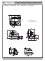 2
2
-
 3
3
-
 4
4
-
 5
5
-
 6
6
-
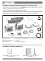 7
7
-
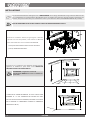 8
8
-
 9
9
-
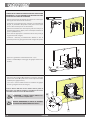 10
10
-
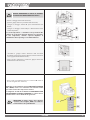 11
11
-
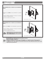 12
12
-
 13
13
-
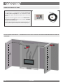 14
14
-
 15
15
-
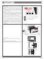 16
16
-
 17
17
-
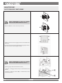 18
18
-
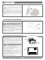 19
19
-
 20
20
-
 21
21
-
 22
22
-
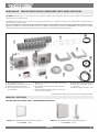 23
23
-
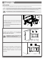 24
24
-
 25
25
-
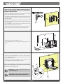 26
26
-
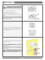 27
27
-
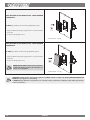 28
28
-
 29
29
-
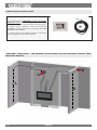 30
30
-
 31
31
-
 32
32
-
 33
33
-
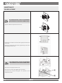 34
34
-
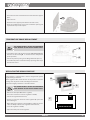 35
35
-
 36
36
-
 37
37
-
 38
38
-
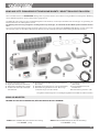 39
39
-
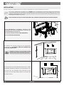 40
40
-
 41
41
-
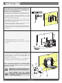 42
42
-
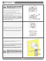 43
43
-
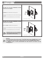 44
44
-
 45
45
-
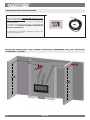 46
46
-
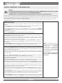 47
47
-
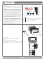 48
48
-
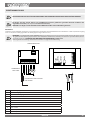 49
49
-
 50
50
-
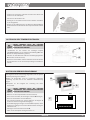 51
51
-
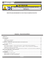 52
52
-
 53
53
-
 54
54
-
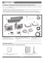 55
55
-
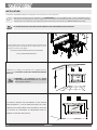 56
56
-
 57
57
-
 58
58
-
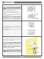 59
59
-
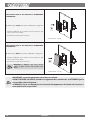 60
60
-
 61
61
-
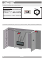 62
62
-
 63
63
-
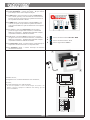 64
64
-
 65
65
-
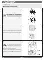 66
66
-
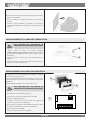 67
67
-
 68
68
-
 69
69
-
 70
70
-
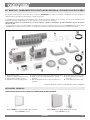 71
71
-
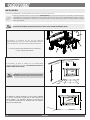 72
72
-
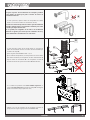 73
73
-
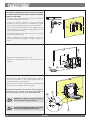 74
74
-
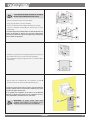 75
75
-
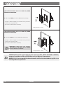 76
76
-
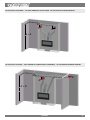 77
77
-
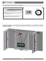 78
78
-
 79
79
-
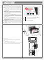 80
80
-
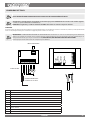 81
81
-
 82
82
-
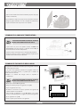 83
83
-
 84
84


La Nordica Wind Air Kit El manual del propietario
- Tipo
- El manual del propietario
en otros idiomas
Artículos relacionados
-
La Nordica Wind Air Kit El manual del propietario
-
La Nordica Wave diffuser for "Wind Air" system El manual del propietario
-
-
-
-
La Nordica Inserto 80 High Pressure El manual del propietario
-
-