
-
N
ote
-
SIMPLEX has taken every care in preparin
g
this Operational Manual that is intended
as a technical
g
uideline only. SIMPLEX accepts no liability in relation to any use o
r
reliance made of an
y
information in this Operational Manual.
All information, illustrations and s
p
ecifi cations in this O
p
erational Manual are based
on the latest information available at the time of publication. The ri
g
ht is reserved to
make chan
g
es at any time without notice.
Equipment operators and installers shall be responsible for ensurin
g
that a safe
workin
g
environment and safe systems of work are in place before operatin
g
the
e
q
ui
p
ment.
©
2008
S
IMPLE
X
C
O
NTENT
S
777 Oakmont Lane, Ste. 800, Westmont, IL 60559
1-800-323-9114 • Outside U.S. 1-630-590-6990
www.tksimplex.com
B
Date - 0713

IMP
O
RTANT RE
C
EIVIN
G
IN
S
TR
UC
TI
O
N
S
IMPORTANT
RECEIVING
INSTRUCTIONS
Visually inspect all components
f
or shipping
d
amage. I
f
any shipping damage is
f
ound,
n
otif
y
carrier at once.
SAFETY INFORMATION - English
SAFETY
INFORMATION
English
STAY
C
LEAR
O
F L
O
ADS SUPP
O
RTED BY HYDRAULI
C
S.
A cylinder should never be used as a load holding device. After raising
t
h
e loa
d
, it s
h
oul
d
b
e supporte
d
b
y
b
locks or
b
y cri
bb
ing.
D
O
N
O
T EXCEED E
Q
UIPMENT RATING
S.
Never attempt to lift a load wei
g
hin
g
more than the capacity of the
cyllinder. Overloading causes equipment failure and possible personal
i
n
j
ury
.
These cylinders are designed
f
or a maximum pressure o
f
10,000 psi
(700 bar). Do not use these cylinders in a system with a hi
g
her
pressure rating.
••• 1 •••
•
••
•••
1
1
•••
•••

•
••
2
•••
BE
S
URE THE CYLINDER I
S
S
TABLE
BEF
O
RE LIFTING L
O
AD
.
The c
y
linder should be placed on a fl at surface
that can su
pp
ort the load. Loads must be
centered on the cylinder plunger.
O
ff-center
l
oads will dama
g
e cylinders and plun
g
ers.
In addition, the load may slip or fall, causing
potentially
d
angerous results.
Distri
b
ute t
h
e loa
d
evenly across t
h
e entire
s
addle
s
urface. Tilt
s
addle
s
are available to
reduce offset loadin
g
.
D
O
N
O
T KINK HYDRAULI
C
H
O
S
E
Avoi
d
s
h
arp
b
en
d
s an
d
kinks w
h
en routing
h
y
draulic hoses.
S
harp bends and kinks will
internally dama
g
e the hose leadin
g
to
premature
f
ailure.
Do not drop sharp or heav
y
objects on hose.
This will cause internal dama
g
e to hose wire
stran
d
s. Applying pressure to a
d
amage
d
h
ose
ma
y
cause it to rupture.
D
O
N
O
T CARRY BY HYDRAULIC H
OS
E
Do not use t
h
e
h
y
d
raulic
h
ose to carry a
h
y
draulic component (i.e. pumps, c
y
linders
and valves
)
.
K
EEP HYDRAULIC E
Q
UIPMENT AWAY
F
R
O
M FLAMES AND HEAT
.
E
xcessive
h
eat will
d
amage
h
y
d
raulic
e
quipment. Heat also weakens
h
ose
m
aterials and packin
g
s. DO NOT expose
e
quipment to temperatures of 150
º
F (65
ºC
) or
h
igher. Protect hoses and cylinders
f
rom weld
s
p
latter.
INSTALLATION
INSTALLATION
M
ake h
y
draulic connections. Use a pump with
a
release valve or a 3-way valve an
d
one
h
ose
f
or single-acting cylinders. Use a pump with a
4
-way valve and two hoses for double-actin
g
c
ylin
d
ers.

•
••
3
•••
Double-actin
g
cylinders must have both couplers connected
.
Fully hand-tighten all couplers. Loose coupler connections can block the
fl
ow o
f
oil
.
2. Bleed air
f
rom the cylinder as shown below.
S
ingle-acting cylinders: Position the cylinder so that the plunger is pointed down and the
c
y
linder is lower than the pump. Full
y
extend and retract the c
y
linder 2 or 3 times.
Double-actin
g
cylinders: Lay the cylinder on its side with the couplers
f
acin
g
up. Fully
extend and retract the c
y
linder 2 or 3 times.
C
ollar threads are rated for the full capacity of the cylinder when fully engaged
.
O
PERATI
ON
O O
D
O
N
O
T HANDLE PRE
SS
URIZED H
OS
E
S.
E
scapin
g
oil under pressure can penetrate the skin, causin
g
s
erious injury or death. I
f
oil is injected under the skin, see a
d
octor
i
mmed
i
ately.
O
perate the h
y
draulic pump to advance and retract the c
y
linder.
S
ome single-acting cylinders are spring-return, others are load return.
T
he speed o
f
retraction is a
ff
ected by the length o
f
the hose and other
r
estrictions in the line. Double-actin
g
cylinders are powered in both
d
irections
b
y t
h
e pump.
The cylinder stop ring is designed to take the
f
ull load. However, to
reduce cylinder wear, use less than
f
ull stroke when possible.
MAINTENAN
C
E
C
1. Use only
S
implex oil with these cylinders.
2. Use dust caps when cylinders are disconnected
f
rom the hose.
Keep entire cylinder clean to prolon
g
cylinder life.
3. Store cylinders up-ri
g
ht and fully retracted to prevent seal
d
istortion.
.

•
••
4
•••
T
R
OU
BLE
S
H
OO
TIN
G
OU S OO G
PR
O
BLEM P
OSS
IBLE
C
A
US
E
S
SSUCSSOO
Cylinder will not advance. Pump release valve open.
Cylinder
will
not
advance.
Pump
release
valve
open.
.denethgit ylluf ton relpuoC
Coupler
not
fully
tightened.
.wol si pmup ni level liO
Oil
level
in
pump
is
low.
Cylinder advances part way. Oil level in pump is low.
Cylinder
advances
part
way.
Oil
level
in
pump
is
low.
Cylinder advances in spurts. Air in hydraulic system.
Cylinder
advances
in
spurts.
Air
in
hydraulic
system.
C
ylinder advances slower
than normal. Leaking connection.
t a o a ea g co ect o
.gninoitcnuflam pmuP
Pump
malfunctioning.
C
y
linder advances but will
.gnikael slaes rednilyC .dloh ton
not
hold.
Cylinder
seals
leaking.
.gninoitcnuflam pmuP
u p a u ct o g
.noitcennoc gnikaeL
ea g co ect o
Cylinder leaks oil. Worn or damaged seals.
Cy de ea s o o o da aged sea s
.egamad rednilyc lanretnI
te a cy de da age
C
y
linder will not retract or
retracts slower than normal. Narrow hose restricting fl ow.
retracts
slower
than
normal.
Narrow
hose
restricting
fl
ow.
.gnirps noitcarter kaew ro nekorB
Broken
or
weak
retraction
spring.
.yllanretni degamad rednilyC
Cy de da aged te a y
O
il leaking from external
relief valve. Coupler not fully ti
g
htened.
T

•
••
5
•••
WI
C
HTI
G
E ANWEI
SU
N
G
EN
F
C G SU G
Ü
Ü
R
DIE EIN
G
AN
GS
K
O
NTR
O
LL
E
G GS O O
Unterziehen
S
ie alle Teile einer
S
ichtkon-
trolle auf eventuelle Trans
p
ortschäden.
Wird ein solcher Transportschaden
f
est-
gestellt, benachrichtigen
S
ie unverzüglich
den S
p
editeur.
SICHERHEITSINFORMATIONEN
-
Deutsch
SICHERHEITSINFORMATIONEN
Deutsch
VON LASTEN FERNBLEIBEN
,
DIE DURCH DAS HYDRAULIKSYS-
TEM ABGEST
Ü
TZT WERDEN.
Ein Hydraulikzylinder dar
f
au
f
keinen Fall als Vorrichtung zur Abstüt-
zung einer Last verwendet werden. Nach Anheben der Last mu
ß
diese
durch Blöcke oder einen Unterbau ab
g
estützt werden.
DIE NENNLEISTUNG DER ANLAGE NI
C
HT ÜBERS
C
HREITEN.
Niemals versuchen, eine Last anzu
g
eben, deren Gewicht die Nennleistun
g
des Hydraulikzylinders überstei
g
t. Durch Überlastun
g
können Schäden an
der Anlage und Körperverletzungen hervorgeru
f
en werden.
Diese Zylinder sind für einen Höchstdruck von 700 bar
(
10.000 psi
)
ausgelegt. Diese Zylinder dürfen nicht in einem
S
ystem mit einer
höheren Drucknennleistun
g
verwendet werden.
V
O
R ANHEBEN EINER LA
S
T
S
ICHER
S
TELLEN, DA
SS
DER ZYLIN
-
DER
S
TABIL I
S
T.
D
er Zylinder muß auf einer ebenen Fläche aufsitzen, die fest
g
enu
g
ist,
um
d
ie Last a
b
zustützen.
Lasten müssen auf dem Z
y
linderkolben
zentriert sein.
S
eitlich versetzte Lasten führen
zu Beschädi
g
un
g
der Zylinder und Kolben.
Darüber hinau
s
könnte die La
s
t in
s
Rut
s
chen
geraten oder fallen, was zu gefährlichen
S
itu-
a
ti
o
n
e
n führ
e
n k
a
nn.
Die Last gleichmä
ß
ig über die gesamte Fläche
de
s
Druck
s
tück
s
verteilen. Um
s
eitliche
s
Ver
s
et-
zen von Lasten zu reduzieren, sind Ki
pp
druck-
stücke er
h
ältlic
h
.

•
••
6
•••
DEN HYDRAULIKS
C
HLAU
C
H NI
C
HT
KNI
C
KEN.
Beim Verle
g
en von Hydraulikschläuchen
scharfe Bie
g
un
g
en und Knicke vermeiden, da
diese zu
S
chäden im Inneren des
S
chlauchs
f
ühren können, was vorzeiti
g
en Ausfall zur
F
olge hat.
Keine scharfkantigen oder schweren Gegen-
stände auf den
S
chlauch fallen lassen, da
dies die Drahtlitzen im Inneren des
S
chlauchs
beschädi
g
en kann. Wenn ein beschädi
g
ter
S
chlauch unter Druck gesetzt wird, kann die-
s
er ber
s
ten.
Den Hydraulikschlauch nicht zum Tra
g
en von
Hy
draulikteilen (z.B. Pumpen, Z
y
lindern und
Ventilen
)
verwenden.
B
E
S
TANDTEILE DE
S
HYDRAULIK
S
Y
S
-
T
EMS V
O
N
O
FFENEM FEUER UND HITZE
FERNHALTEN.
Ü
bermäßige Hitze beschädigt Hydraulikan-
l
a
g
en. Darüber hinaus schwächt Hitze das
S
chlauchmaterial und die Dichtungen. Die
Anlage keinen Temperaturen über 65 °
C
(150
°
F) aussetzen. Schläuche und Z
y
linder beim
S
chweißen vor
S
pritzern schützen.
IN
S
TALLATI
ON
INSTALLATION
Hy
d
raulikver
b
in
d
ungen
h
erstellen. Eine Pumpe
m
it Löseventil o
d
er Dreiwegeventil un
d
einem
S
chlauch für einfachwirkende Z
y
linder verwen-
d
en. Eine Pumpe mit einem Vierwegeventil un
d
zwei
S
chläuchen für doppeltwirkende Zylinder
v
e
rw
e
n
de
n.
B
ei doppeltwirkenden Z
y
lindern müssen
b
eide Kupplun
g
en an
g
eschlossen sein
.
Alle Kupplungen von Han
d
vollkommen
f
estziehen. Lose Kupplün
g
stucke können zu
E
inschränkung des
Ö
lfl usses führen.

•
•• 7 •••
2. Die Luft
g
emäß der untenstehenden Abbildun
g
aus dem Zylinder ablassen
Einfachwirkende Zylinder: Den Zylinder so ausrichten, daß der Kolben nach unten zeigt
un
d
d
er Zylin
d
er nie
d
riger liegt als
d
ie Pumpe. Den Zylin
d
er zwei - o
d
er
d
reimal voll aus
- un
d
e
inf
a
hr
e
n.
Doppeltwirkende Zylinder: Den Zylinder auf die Seite le
g
en, so daß die Kupplun
g
en nach
oben zeigen. Den Zylinder zwei - oder dreimal voll aus - und einfahren.
Bei vollst
ä
ndiger Einschraubung sind die Bundgewinde auf die volle Nennleistung
des Zyl
i
nders ausgelegt.
BETRIEB
KEINE UNTER DRU
C
K STEHENDEN S
C
HLÄU
C
HE HANDHABEN.
Ö
l, das unter Druck entweicht, kann die Haut durchdrin
g
en und
schwere Verletzungen oder Tod verursachen. Falls
Ö
l unter die
Haut
g
elan
g
t, sofort einen Arzt aufsuchen.
Die Hydraulikpumpe zum Aus - und Ein
f
ahren des Zylinders betätigen.
Einige ein
f
achwirkende Zylinder werden mittels Federung zurück-
g
ezo
g
en, andere unter Belastun
g
. Die Geschwindi
g
keit des Rückzu
g
s
hän
g
t von der Län
g
e des Schlauches und anderen Veren
g
un
g
en in der
Leitung a
b
. Doppeltwirken
d
e Zylin
d
er wer
d
en in
b
ei
d
en Ric
h
tungen
durch die Pumpe bewe
g
t.
Der Zylinder-Sperrin
g
ist so aus
g
ele
g
t, daß er die volle Belastun
g
trä
g
t.
Jedoch sollte der Zylinder nach Möglichkeit nicht voll ausgefahren
wer
d
en, um
d
ie A
b
nutzung gering zu
h
alten.
WART
U
N
G
U G
1. Mit diesen Zylindern nur Simplex-
Ö
l verwenden.
2. Wenn die Zylinder vom
S
chlauch getrennt werden,
S
taubschutzkap-
pen anbrin
g
en. Um die Lebensdauer des Zylinders zu verlän
g
ern,
den gesamten Zylinder sauber halten.
3. Die Zylinder au
f
recht und in voll einge
f
ahrenem Zustand lagern, um
eine Verwin
d
ung
d
er Dic
h
tungen zu vermei
d
en.

•
••
8
•••
FEHLERSUCHE
FEHLERSUCHE
PROBLEM MÖGLICHE URSACHEN
PROBLEM
MÖGLICHE
URSACHEN
Zylinder fährt nicht aus. Pumpen-Druckentlastungsventil offen.
Zylinder
fährt
nicht
aus.
Pumpen Druckentlastungsventil
offen.
Kupplung nicht ganz festgezogen.
upp u g c t ga estge oge
Niedriger Ölstand in der Pumpe.
ed ge Ö sta d de u pe
Zylinder fährt nur teilweise aus. Niedriger Ölstand in der Pumpe.
y de ä t u te e se aus ed ge Ö sta d de u pe
Zylinder fährt stoßweise aus. Luft im Hydrauliksystem.
y de ä t stoß e se aus u t yd au syste
Z
ylinder fährt lan
g
samer
als normal aus. Undichte Verbindung.
als
normal
aus.
Undichte
Verbindung.
Funktionsstörung der Pumpe.
Funktionsstörung
der
Pumpe.
Z
ylinder
f
ährt aus, hält
aber nicht. Zylinderdichtungen undicht.
tcduegutcdedytceba
Funktionsstörung der Pumpe.
Funktionsstörung
der
Pumpe.
Undichte Verbindung.
Undichte
Verbindung.
Z
ylinder leckt Öl. Dichtun
g
en ab
g
enutzt
ode
r
sc
h
ad
h
aft
.
ode sc ad a t
Schaden im Zylinderinneren.
Sc ade y de e e
Z
ylinder
f
ährt nicht zurück
o
der fährt lan
g
samer als En
g
stelle im Schlauch schränkt
no
rm
a
l z
u
r
üc
k.
Ö
lfl
uß
e
in.
normal
zurück.
Ölfl
uß
ein.
Rückzug
f
eder schadha
f
t
ode
r
sch
w
ach
.
ode sc ac
Schäden im Zylinderinneren.
Schäden
im
Zylinderinneren.
Ö
llecka
g
e am äußeren
E
ntlastun
g
sventil. Kupplun
g
nicht
g
anz fest
g
ezo
g
en.

•
••
9
•••
INSTRUCTIONS IMPORTANTES CONCERNANT
LA RÉCEPTION
LA
RÉCEPTION
E
xaminer visuellement toutes les
p
ièces
p
our voir si elles ont
é
t
é
endommag
é
es
e
n cours de transport.
S
ignaler imm
é
di-
a
tement au transporteur les dé
g
âts ainsi
c
onstat
é
s.
INF
O
RMATI
O
N
S
CO
N
C
ERNANT LA
S
É
CU
RITÉ - Fr
a
n
ca
i
s
O O S CO C S CU a ca s
RESTER
À
Lʼ
É
CART DES CHARGES SUPPORT
É
ES PAR DES
V
É
RINS HYDRAULI
Q
UES
.
Un vérin ne doit jamais être utilisé pour maintenir une char
g
e. Une
fois la charge soulev
é
e, elle doit
ê
tre soutenue par des cales ou un
ca
d
re porteur.
NE PAS D
É
PASSER LA CAPACIT
É
NOMINALE DU MAT
É
RIEL
N
e jamais essayer de soulever une char
g
e plus lourde que celle
autorisée par la capacité nominale du vérin. Le leva
g
e dʼune char
g
e
trop lourde peut endommager le mat
é
riel et entra
î
ner des blessures.
Ces vérins sont con
ç
us pour une pression maximale de 700 bars
(10,000 psi). Ne pas les utiliser dans un syst
è
me dont la pression
nominale est
p
lus élevée.
SʼASSURER DE LA STABILIT
É
DU V
É
RIN
AVANT DE S
O
ULEVER UNE
C
HARGE.
Le v
é
rin doit
ê
tre plac
é
sur une surface plane
capa
b
le
d
e supporter la c
h
arge.
L
es charges doivent
ê
tre centr
é
es sur le piston
du vérin. Les char
g
es décentrées endomma-
g
ent les vérins et leurs plon
g
eurs. En outre, la
ch
arge risque
d
e glisser ou
d
e tom
b
er, avec
des conséquences potentiellement dan
g
ere-
us
e
s
.
R
épartir la char
g
e uniformément sur toute la
sur
f
ace dʼappui. Des coussinets dʼappui basculants sont disponibles
pour limiter le d
é
centrement de la charge.

•
•• 1
0
••
•
NE PA
S
VRILLER LE FLEXIBLE HYDRA
U-
LI
Q
UE
.
Éviter de plier et de vriller les fl exibles h
y
-
drauli
q
ues lors de leur acheminement. Les
pliages et vrillages endommagent lʼint
é
rieur
d
es fl exibles, ce
q
ui conduit à une défaillance
p
rématurée de ceux-ci.
Ne pas laisser tomber dʼobjets lourds sur un
fl exible.
C
ela endommage ses torons métal-
li
q
ues et ris
q
ue de causer sa ru
p
ture lors
q
uʼil
est mis sous
p
ression.
Ne pas se servir du fl exible h
y
draulique pour
transporter un organe hydraulique
(
tel que
p
om
p
e, vérin ou vanne).
T
ENIR LE MATÉRIEL HYDRAULI
Q
UE À
L
ʼ
É
CART DES FLAMMES ET DES SOURC-
ES
DE CHALEUR.
U
ne chaleur excessive endomma
g
e le ma-
té
riel hydraulique. Elle affaiblit
é
galement les
m
at
é
riaux dont sont fabriqu
é
s les fl exibles et
l
es
g
arnitures. NE PAS exposer le matériel à
d
es températures de 65 °C (150 °F) et plus.
P
rot
é
ger les fl exibles et les v
é
rins des
é
cla-
b
ou
ss
ure
s
de
s
oudure.
INSTALLATION
INSTALLATION
E
ffectuer les branchements h
y
drauliques.
U
tiliser une pompe
à
soupape de s
û
ret
é
ou
s
oupape
à
3 voies et un seul fl exible pour les
vérins à sim
p
le effet. En utiliser une à sou
p
a
p
e
à
4 voies et deux fl exibles pour les v
é
rins
à
d
ouble e
ff
et.
l
es deux raccords des v
é
rins à double effet
do
iv
e
nt
ê
tr
e
bran
c
h
és
.
B
ien serrer tous les raccords
à
la main. Des
r
accords mal serr
é
s peuvent g
ê
ner la circula-
t
i
o
n
de
lʼhuil
e
.

•••
1
1 •••
2
. Pur
g
er le vérin de lʼair quʼil contient comme indiqué ci-dessous.
V
é
rin
à
simple effet : positionner le v
é
rin de façon
à
ce quʼils soit plus bas que la pompe
et que son piston soit dirig
é
vers le bas. Lʼ
é
tirer et le r
é
tracter
à
fond 2 ou 3 fois.
V
é
rin
à
double effet : coucher le v
é
rin sur le c
ô
t
é
en plaçant les raccords sur le dessus.
L
ʼétirer et le rétracter à fond 2 ou 3 foi
s
.
lorsque les raccords sont serrés à fond, leur fi leta
g
e a une résistance nominale
correspondant à la capacit
é
du v
é
rin.
F
O
N
C
TI
O
NNEMENT
O C O
N
E PA
S
MANIPULER DE FLEXIBLE
S
SO
U
S
PRE
SS
I
ON
E
n cas de fuite, lʼhuile sous
p
ression
p
eut traverser la
p
eau
e
t occas
i
onner des blessures graves, vo
i
re mortelles. En cas
d
ʼinjection dʼhuile sous la peau, consulter un m
é
decin imm
é
diate
-
me
nt.
Actionner la pompe hydraulique pour
é
tirer et r
é
tracter le v
é
rin.
S
ur
c
ertains v
é
rins
à
simple effet, la r
é
traction se fait pas ressort ; sur
d
ʼautres, elle se fait sous lʼaction de la char
g
e. La vitesse de rétraction
e
st fonction de la longueur du fl exible et dʼautres facteurs affectant la
p
ression dans la conduite. Les v
é
rins
à
double effet sont actionn
é
s par
l
a
p
om
p
e dans les deux sens.
L
a bague dʼarrêt du vérin est con
ç
ue pour supporter la charge com-
p
l
è
te. Toutefois, dans la mesure du possible, ne pas utiliser le v
é
rin
à
f
ond de course pour r
é
duire son usure.
ENTRETIEN
1
. Nʼutiliser que de lʼhuile
S
implex avec ces v
é
rins.
2
. Poser des capuchons anti-poussi
è
re lorsque les fl exibles sont d
é
-
b
ranchés des vérins. Veiller à ce
q
ue tout le vérin reste
p
ro
p
re
p
our
p
rolonger sa dur
é
e de service.
3
. Entre
p
oser les v
é
rins debouts et enti
è
rement r
é
tract
é
s
p
our em
pê
ch-
e
r une d
é
formation de leurs joints.

•
•• 1
2
••
•
D
É
PANNA
G
E
G
PR
O
BL
È
ME
C
A
US
E P
OSS
IBL
E
SSOSUCO
Le vérin ne sʼétire
p
as. Sou
p
a
p
e de sûreté de la
.etrevuo epmop
pompe
ouverte.
R
acco
r
d
m
a
l
se
rr
é
.
Raccord
mal
serré.
.epmop al snad eliuhʼd uaevin saB
Le vérin sʼétire partiellement. Bas niveau dʼhuile dans la pompe.
e é s ét e pa t e e e t as eau d u e da s a po pe
Le v
é
rin sʼ
é
tire par saccades. Pr
é
sence dʼair dans le
.euqiluardyh tiucric
circuit
hydraulique.
Le vérin sʼétire
p
lus lentement
quʼil ne le devrait normalement. Fuite dans un raccord
qu e e de a t o a e e t u te da s u acco d
siavuaM
f
onctionnement
.epmop al ed
de
la
pompe.
Le vérin sʼétire
,
mais ne
maintient pas la charge. Fuites des joints du vérin.
maintient
pas
la
charge.
Fuites
des
joints
du
vérin.
epmop al ed tnemennoitcnof siavuaM
au a s o ct o e e t de a po pe
F
u
i
te
da
n
s
u
n r
acco
r
d
.
u te da s u acco d
De lʼhuile fuit du vérin. Joints usés ou endommagés.
e u e u t du é Jo ts usés ou e do agés
.tnemerueirétni égammodne niréV
é e do agé té eu e e t
Le vérin ne se rétracte
p
as ou
le fait plus lentement quʼil ne Circulation
g
ênée par un
le devrait normalement. fl exible de trop petit diamètre
e de a t o a e e t e b e de t op pet t d a èt e
R
esso
r
t
de
r
ét
r
act
i
o
n
cassé
ou
f
a
i
b
l
e
.
esso t de ét act o cassé ou a b e
.tnemerueirétni égammodne niréV
é e do agé té eu e e t
De lʼhuile fuit de la sou
p
a
p
e
de
s
ûreté extérieure. Raccord mal
s
erré.

••• 1
3
••
•
IN
S
TR
UCC
I
O
NE
S
IMP
O
RTANTE
S
PARA LA RE
C
EP
C
I
Ó
N
S UCC O S O S C C Ó
I
nspeccione visualmente to
d
os los com-
p
onentes
p
ara ver si han sufrido daños
durante el transporte.
S
i existe alg
ú
n
deterioro comun
í
quelo inmediatamente al
trans
p
ortista.
INFORMACIÓN SOBRE SEGURIDAD - Espanol
INFORMACIÓN
SOBRE
SEGURIDAD
Espanol
MANTÉNGASE ALEJAD
O
DE LAS
C
ARGAS S
O
STENIDAS P
O
R
DISPOSITIVOS HIDR
Á
ULICOS
.
Nunca debe usarse un cilindro hidr
á
ulico como dispositivo para sujetar
car
g
as. Después de levantar la car
g
a, ésta debe ser sustentada por
bloques o por un armaz
ó
n de sustentaci
ó
n.
N
O
EXCEDA LA
S
CAPACIDADE
S
DEL E
Q
UIP
O
Nunca intente levantar una carga que exce
d
a la capaci
d
a
d
d
el cilin
d
ro.
La sobrecar
g
a puede causar fallos del equipo y lesiones personales.
Estos cilindros están diseñados
p
ara una
p
resión máxima de 10.000
psi (700 bar). No use estos cilindros en un sistema cuya presi
ó
n nomi-
na
l
sea mayor.
A
NTE
S
DE LEVANTAR LA CARGA,
A
SEGÚRESE DE
Q
UE EL CILINDRO SEA
ES
TABLE.
E
l cilin
d
ro
d
e
b
e estar coloca
d
o so
b
re una
s
uperfi cie plana capaz de soportar la car
g
a.
L
as car
g
as deben estar centradas sobre el
é
mbolo del cilindro. Las cargas descentradas
d
añar
á
n los cilindros y los
é
mbolos. Adem
á
s, la
c
ar
g
a podría resbalar y caerse, con resultados
p
otenc
i
a
l
mente pe
li
grosos.
Distribuya la carga uni
f
ormemente sobre toda la super
fi
cie del asiento
del cilindro.
S
e puede disponer de asientos inclinables que ayudan a
reducir el descentrado de las car
g
as.

•
•• 1
4
••
•
NO
RETUERZA LA MANGUERA HIDRÁU-
L
I
C
A
E
vite las curvas pronunciadas
y
no retuerza
l
as man
g
ueras hidráulicas al colocarlas. Este
t
ipo de deformaciones causar
á
daños internos
a
la man
g
uera, provocando fallos prematuros
d
e la misma.
N
o deje caer objetos pesados ni afi lados
s
obre una manguera. Esto causar
á
daños
i
nternos en los alambres de la man
g
uera. Si
s
e aplica presión a una man
g
uera dañada, se
p
odr
í
a causar su rotura.
N
o utilice una manguera hidr
á
ulica para
a
carrear un com
p
onente hidráulico (es decir,
b
ombas, cilindros
y
válvulas).
M
ANTENGA EL EQUIPO HIDR
Á
ULICO ALE
-
J
AD
O
DEL FUEG
O
Y DEL CAL
O
R.
E
l calor excesivo dañará el e
q
ui
p
o hidráulico.
T
ambi
é
n debilitar
á
el material y las empaqu-
e
taduras de las mangueras. N
O
exponga el
eq
ui
p
o a tem
p
eraturas de 150°F (65°C) o su-
p
eriores. Proteja las mangueras y los cilin
d
ros
d
e las salpica
d
uras
d
e sol
d
a
d
ura.
IN
S
TALA
C
I
Ó
N
S C Ó
C
onecte los componentes hidráulicos. Use
u
n
a
b
o
mb
a
c
o
n un
a
v
á
lvul
a
de
a
livi
o
o
un
a
v
á
lvula de 3 v
í
as y una manguera para los
c
ilindros de acci
ó
n
ú
nica. Use una bomba con
u
na válvula de 4 vías y dos man
g
ueras para
l
os cilindros de doble acci
ó
n.
L
os cilindros de doble acci
ó
n deben tener
a
m
b
os acop
l
a
d
ores conecta
d
os.
A
p
riete todos los aco
p
ladores manualmente.
L
as conexiones
fl
o
j
as pueden bloquear el
fl
u
j
o
d
el aceite.

••• 1
5
••
•
2. Pur
g
ue el aire del cilindro como se muestra a continuación.
C
ilindros de acción única:
C
oloque el cilindro de modo que el émbolo apunte hacia abajo
y el cilindro est
é
m
á
s bajo que la bomba. Extienda y retraiga el cilindro del todo 2
ó
3
vece
s
.
Cilindros de acción doble: Colo
q
ue el cilindro sobre el costado con los aco
p
ladores hacia
arriba. Extienda y retraiga el cilindro del todo 2
ó
3 veces.
Las roscas del collarín est
á
n graduadas para la capacidad total del cilindro cuando
est
é
n totalmente engranadas.
FUNCIONAMIENTO
FUNCIONAMIENTO
N
O
MANIPULE MANGUERAS PRESURIZADAS.
Un escape de fl uido hidráulico a presi
ó
n puede penetrar la piel,
causando lesiones graves o la muerte.
S
i se inyectase fl uido bajo
la
p
iel, consulte a un médico de inmediato
.
Accione la bomba hidr
á
ulica para extender y retraer el cilindro.
Algunos cilindros de acci
ó
n
ú
nica tienen retorno por resorte; otros
tienen retorno por acción de la car
g
a. La velocidad de retracción se
ve afectada por la longitud de la manguera y otras restricciones en la
l
í
nea. Los cilindros de doble acci
ó
n son impulsados en ambos sentidos
p
or la bomba.
El casquillo de tope del cilindro está diseñado para aceptar la car
g
a
total.
S
in embargo, para reducir el desgaste del cilindro, use menos
d
el total
d
e la carrera siempre que sea posi
b
le.
MANTENIMIENT
O
O
1. Utilice solamente aceite
S
implex con estos cilindros.
2. Use tapas guardapolvo cuando los cilindros est
é
n desconectados
de la man
g
uera. Manten
g
a limpio el cilindro en su totalidad para
prolongar la vida
ú
til del mismo.
3. Guarde los cilindros en posición vertical y totalmente retraídos para
evitar que lo sellos se de
f
ormen.

•
•• 1
6
••
•
L
OC
ALIZA
C
I
Ó
N DE AVERÍA
S
OC C Ó S
PR
O
BLEMA
C
A
US
A
S
P
OS
IBLE
S
SSOSSUCO
El cilin
d
r
o
n
o
a
v
a
nz
a
. L
a
v
á
lvul
a
de
a
livi
o
de
l
a
bomba está abierta.
bomba
está
abierta.
átse on rodalpoca lE
.odaterpa etnemlatot
tota e te ap etado
.abmob al ne etieca ed ojab leviN
e bajo de ace te e a bo ba
El cilindro avanza parcialmente. Nivel bajo de aceite en la bomba.
El
cilindro
avanza
parcialmente.
Nivel
bajo
de
aceite
en
la
bomba.
El cilin
d
r
o
a
v
a
nz
a
de
f
o
rm
a
.ociluárdih ametsis le ne eriA .ralugerri
irregular.
Aire
en
el
sistema
hidráulico.
El cilindro avanza m
á
s
lentamente que lo normal. Fugas en la conexión.
e ta e te que o o a ugas e a co e ó
Mal funcionamiento de la bomba.
Mal
funcionamiento
de
la
bomba.
El cilindro avanza
p
ero no
retiene su posición. Fugas en los sellos del cilindro.
retiene
su
posición.
Fugas
en
los
sellos
del
cilindro.
M
a
l
fu
n
c
i
o
n
a
mi
e
n
to
de
l
a
bo
m
ba
.
a u c o a e to de a bo ba
.nóixenoc al ne saguF
ugas e a co e ó
Fugas de aceite en el cilindro. Sellos desgastados o dañados.
ugas de ace te e e c d o Se os desgastados o da ados
D
a
ñ
os
in
te
rn
os
e
n
e
l
c
ilin
d
r
o
.
a os te os e e c d o
El cilindro no se retrae
,
o se
retrae más lentamente Una man
g
uera demasiado
que lo normal. delgada limita el fl ujo .
que o o a de gada ta e ujo
iccarter ed etroseR
ó
n roto
o debilitado.
o
debilitado.
Daños internos en el cilindro.
Daños
internos
en
el
cilindro.
Fu
g
as de aceite por la válvula El acoplador no está
d
e alivio externa. apreta
d
o
d
el to
d
o.

••• 17 ••
•
IMP
O
RTANTI I
S
TR
U
ZI
O
NI DI RI
C
EZI
O
N
E
O S U O C O
C
ontrollare tutti i componenti per accertare
eventuali danni derivanti dal tras
p
orto. Se si
rilevano
d
anni, avvisare su
b
ito il vettore.
INF
O
RMAZI
O
NI
SU
LLA
S
I
CU
REZZA - I
ta
li
a
n
o
O O SU S CU ta a o
TENER
S
I L
O
NTANI DA CARICHI
SOS
TENUTI DA DI
S
P
OS
ITIVI
O
LE
O
DINAMICI
.
Non utilizzare mai un cilindro come dispositivo di soste
g
no di un
carico. Dopo aver sollevato il carico, sostenerlo me
d
iante
b
locc
h
i o
unʼarmatura
d
i legno.
N
O
N
S
UPERARE LE P
O
RTATE N
O
MINALI DEGLI APPARECCHI.
Non tentare mai di sollevare un carico di
p
eso su
p
eriore alla
p
ortata
del cilindro. Un sovraccarico provoca guasti dellʼapparecchio e pu
ò
causare in
f
ortuni.
Q
uesti cilindri sono realizzati per una pressione massima di 700 bar
(10.000
p
si). Non utilizzarli in un sistema con una
p
ressione nominale
super
i
ore.
PRIMA DI
SO
LLEVARE IL CARIC
O
, ACCERTAR
S
I CHE IL CILIN
-
D
R
O
S
IA
S
TABILE.
I
l cilindro va collocato su una su
p
erfi cie
p
iana
i
n gra
d
o
d
i sostenere il carico.
I
caric
h
i
d
evono essere centrati sul pistone
d
el cilin
d
ro. I caric
h
i
d
isassati causano
d
anni
a
i cilindri e ai
p
istoni. Inoltre il carico
p
otrebbe
s
civolare o ca
d
ere e ne possono
d
erivare
c
on
d
izioni pericolose.
D
istribuire il carico in modo uni
f
orme sullʼintera
s
u
p
erfi cie della sella. Sono dis
p
onibili selle in-
c
lina
b
ili, per ri
d
urre il
d
isassamento
d
ei caric
h
i.

•
•• 1
8
••
•
N
O
N ATT
O
R
C
IGLIARE TUBI FLESSIBILI
.
Q
uando si dispongono i tubi fl essibili, evitare
che siano so
gg
etti a carichi torsionali e curva-
ture eccessive, perché si possono danne
gg
i-
are e possono per
d
ere prematuramente la loro
f
unzi
o
n
a
lit
à
.
Non lasciar cadere o
gg
etti pesanti sui tubi
fl essibili, perché se ne danneggerebbero gli
strati di
fi
bre intrecciate. Un tubo
fl
essibile dan-
ne
gg
iato può spezzarsi quando è percorso da
fl uido in
p
ressione.
Non utilizzare un tubo fl essibile
p
er tras
p
ortare
un componente oleodinamico
(
per esempio
p
om
p
e, cilindri e valvole).
T
ENERE GLI APPARE
CC
HI
O
LE
O
DINAMI
C
I
LO
NTANI DA FIAMME E F
O
NTI DI CAL
O
RE
.
L
e temperature eccessive
d
anneggiano gli
app
arecchi oleodinamici e indeboliscono i ma-
t
eriali e le guarnizioni dei tubi fl essibili. NON
e
sporre gli apparecc
h
i a temperature uguali o
m
a
gg
iori di 65 °C. Prote
gg
ere i tubi fl essibili e i
c
ilin
d
ri
d
agli spruzzi
d
i sal
d
atura.
IN
S
TALLAZI
O
N
E
INSTALLAZIONE
E
seguire i collegamenti oleodinamici. Con i
c
ilindri a semplice e
ff
etto, usare una pompa
c
on una valvola di
s
carico o una valvola a 3
vie e un tubo fl essibile. Con i cilindri a doppio
eff
etto, usare una pompa con una valvola a 4
vie e due tubi fl e
ss
ibili.
N
ei cilindri a do
pp
io effetto devono essere
c
ollegat
i
entramb
i
gl
i
attacch
i.
S
errare bene, a mano, tutti gli attacchi.
S
e gli
a
ttacchi non sono saldi, il fl usso dellʼolio si
p
uò
b
loccare.

••• 1
9
••
•
2. Disaerare il cilindro come illustrato qui di se
g
uito.
C
ilindri a semplice effetto: collocare il cilindro a unʼaltezza inferiore rispetto alla pompa
e con il pistone rivolto verso il
b
asso. Fare eseguire al cilin
d
ro 2 o 3 corse complete
d
i
e
s
ten
s
ione e ritrazione.
Cilindri a doppio effetto: collocare il cilindro su un fi anco, con
g
li attacchi rivolti verso
lʼalto. Fare eseguire al cilin
d
ro 2 o 3 corse complete
d
i estensione e ritrazione.
Si garantisce lʼadeguatezza dei fi letti delle bussole alla portata del cilindro se sono
completamente
i
mpegnat
i.
USO
USO
N
O
N MANEGGIARE TUBI FLESSIBILI
C
HE
CO
NTENG
O
N
O
O
LI
O
IN PRE
SS
I
O
N
E
Se lʼolio in pressione fuoriesce, pu
ò
penetrare nella pelle e cau
-
sare lesioni
g
ravi, anche mortali. Se si subisce un tale infortunio,
r
i
ch
i
edere
i
mmed
i
atamente ass
i
stenza med
i
ca.
Azionare la pompa oleo
d
inamica per coman
d
are il movimento
d
i este-
nsione e ritrazione del cilindro. Nei cilindri a sem
p
lice effetto il movi-
mento di ritorno è assicurato da una molla o da un contrappeso. La
velocit
à
di ritrazione dipende dalla lunghezza del tubo fl essibile e dagli
strozzamenti nelle tubazioni. Nei cilindri a do
pp
io effetto il movimento
in entrambi i sensi è prodotto dalla pompa.
Lʼanello di battuta del cilindro
è
realizzato in modo da assorbire il carico
massimo. Tuttavia, per ridurre lʼusura del cilindro
è
bene non fare
ese
g
uire a esso corse complete o
g
niqualvolta possibile.
MANUTENZIONE
MANUTENZIONE
1. Con
q
uesti cilindri si deve usare solo olio SIMPLEX.
2. Quando i cilindri non sono colle
g
ati ai tubi fl essibili, prote
gg
erne le
bocche con ta
pp
i
p
ara
p
olvere. Mantenere lʼintero cilindro
p
ulito a
f
-
fi nch
é
la sua durata sia massima.
3. Per evitare de
f
ormazioni delle guarnizioni, i cilindri non usati vanno
dis
p
osti verticalmente e con lo stelo com
p
letamente retratto.

•
••
20
••
•
T
R
OU
BLE
S
H
OO
TIN
G
OU S OO G
PR
O
BLEMA
C
A
US
E P
OSS
IBILI
SSOSUCO
Non viene ese
g
uito il
movimento di estensione. Valvola di scarico della pompa aperta.
movimento
di
estensione.
Valvola
di
scarico
della
pompa
aperta.
A
ttacco
n
o
n
se
rr
ato
be
n
e
.
Attacco
non
serrato
bene.
Q
uantità insuffi ciente di
.apmop allen oilo
o o e a po pa
Il movimento di e
s
ten
s
ione
viene ese
g
uito in modo Quantità insuffi ciente
.apmop allen oilo id .elaizrap
apopaeoodeaap
Il movimento
d
i estensione
viene eseguito a scatti. Aria nellʼimpianto oleodinamico.
viene
eseguito
a
scatti.
Aria
nell impianto
oleodinamico.
Il movimento di e
s
ten
s
ione è
più lento del normale. Collegamenti non a tenuta.
p ù e to de o a e Co ega e t o a te uta
.asottefid apmoP
o pa d ettosa
Il movimento
d
i estensione
viene ese
g
uito, ma non
vi
e
n
e
m
a
n
te
n
uto
.
Gua
rnizi
o
ni
de
l
c
ilin
d
r
o
n
o
n
a
te
n
uta
.
viene
mantenuto.
Guarnizioni
del
cilindro
non
a
tenuta.
.asottefid apmoP
o pa d ettosa
.atunet a non itnemagelloC
Co ega e t o a te uta
Fughe di olio dal cilindro. Guarnizioni usurate o danneggiate.
ug e d o o da c d o Gua o usu ate o da egg ate
D
a
nni in
te
rni
a
l
c
ilin
d
r
o
.
a te a c d o
Il movimento di ritrazione non Portata ba
ss
a dellʼolio a
viene ese
g
uito oppure è più causa della sezione insuffi ciente del
l
e
n
to
de
l n
o
rm
a
l
e
.
tubo
fl
ess
i
b
il
e
.
e to de o a e tubo ess b e
.elobed o atazzeps onrotir id alloM
o a d to o spe ata o debo e
D
a
nni in
te
rni
a
l
c
ilin
d
r
o
.
a te a c d o
Fu
g
he di olio dalla valvola
di
s
icurezza e
s
terna. Attacco non
s
errato bene.
T

S
IMPLEX PR
O
DU
C
TS ARE WARRANTED T
O
BE FREE
O
F DEFE
C
TS IN MATERIALS AND W
O
RKMANSHIP UNDER
N
ORMAL USE FOR AS LONG AS THE ORIGINAL PURCHASER OWNS THEM, SUBJECT TO THE GUIDELINES AND
L
IMITATIONS LISTED. THIS WARRANTY DOES NOT COVER : NORMAL WEAR AND TEAR, COSMETIC ITEMS, ABUSE,
OVERLOADING, ALTERATIONS. IMPROPER FLUID, OR USE IN A MANNER FOR WHICH THEY ARE NOT INTENDED.
IF THE CUSTOMER BELIEVES A PRODUCT IS DEFECTIVE, THE PRODUCT MUST BE DELIVERED, OR SHIPPED
F
REIGHT PREPAID, TO THE NEAREST SIMPLEX AUTHORIZED SERVICE CENTER FOR EVALUATION AND REPAIR
.
777 Oakmont Lane, Ste. 800, Westmont, IL 60559
1-800-323-9114 • Outside U.S. 1-630-590-6990
www.tksimplex.com
777 Oakmont Lane, Ste. 800
Westmont, IL 60559
Phone: 1-630-590-6990
Fax: 1-630-590-6955
Transcripción de documentos
777 Oakmont Lane, Ste. 800, Westmont, IL 60559 1-800-323-9114 • Outside U.S. 1-630-590-6990 www.tksimplex.com B Date - 0713 CONTENTS - Note SIMPLEX has taken every care in preparing this Operational Manual that is intended as a technical guideline only. SIMPLEX accepts no liability in relation to any use or reliance made of any information in this Operational Manual. All information, illustrations and specifications in this Operational Manual are based on the latest information available at the time of publication. The right is reserved to make changes at any time without notice. Equipment operators and installers shall be responsible for ensuring that a safe working environment and safe systems of work are in place before operating the equipment. ©2008 SIMPLEX ••• 11 ••• IMPORTANT RECEIVING INSTRUCTIONS Visually inspect all components for shipping damage. If any shipping damage is found, notify carrier at once. SAFETY INFORMATION - English STAY CLEAR OF LOADS SUPPORTED BY HYDRAULICS. A cylinder should never be used as a load holding device. After raising the load, it should be supported by blocks or by cribbing. DO NOT EXCEED EQUIPMENT RATINGS. Never attempt to lift a load weighing more than the capacity of the cyllinder. Overloading causes equipment failure and possible personal injury. These cylinders are designed for a maximum pressure of 10,000 psi (700 bar). Do not use these cylinders in a system with a higher pressure rating. ••• 2 ••• BE SURE THE CYLINDER IS STABLE BEFORE LIFTING LOAD. The cylinder should be placed on a flat surface that can support the load. Loads must be centered on the cylinder plunger. Off-center loads will damage cylinders and plungers. In addition, the load may slip or fall, causing potentially dangerous results. Distribute the load evenly across the entire saddle surface. Tilt saddles are available to reduce offset loading. DO NOT KINK HYDRAULIC HOSE Avoid sharp bends and kinks when routing hydraulic hoses. Sharp bends and kinks will internally damage the hose leading to premature failure. Do not drop sharp or heavy objects on hose. This will cause internal damage to hose wire strands. Applying pressure to a damaged hose may cause it to rupture. DO NOT CARRY BY HYDRAULIC HOSE Do not use the hydraulic hose to carry a hydraulic component (i.e. pumps, cylinders and valves). KEEP HYDRAULIC EQUIPMENT AWAY FROM FLAMES AND HEAT. Excessive heat will damage hydraulic equipment. Heat also weakens hose materials and packings. DO NOT expose equipment to temperatures of 150ºF (65ºC) or higher. Protect hoses and cylinders from weld splatter. INSTALLATION INSTALLATION Make hydraulic connections. Use a pump with a release valve or a 3-way valve and one hose for single-acting cylinders. Use a pump with a 4-way valve and two hoses for double-acting cylinders. ••• 3 ••• Double-acting cylinders must have both couplers connected. Fully hand-tighten all couplers. Loose coupler connections can block the flow of oil. 2. Bleed air from the cylinder as shown below. Single-acting cylinders: Position the cylinder so that the plunger is pointed down and the cylinder is lower than the pump. Fully extend and retract the cylinder 2 or 3 times. Double-acting cylinders: Lay the cylinder on its side with the couplers facing up. Fully extend and retract the cylinder 2 or 3 times. Collar threads are rated for the full capacity of the cylinder when fully engaged. OPERATION O O DO NOT HANDLE PRESSURIZED HOSES. Escaping oil under pressure can penetrate the skin, causing serious injury or death. If oil is injected under the skin, see a doctor immediately. Operate the hydraulic pump to advance and retract the cylinder. Some single-acting cylinders are spring-return, others are load return. The speed of retraction is affected by the length of the hose and other restrictions in the line. Double-acting cylinders are powered in both directions by the pump. The cylinder stop ring is designed to take the full load. However, to reduce cylinder wear, use less than full stroke when possible. MAINTENANCE C 1. Use only Simplex oil with these cylinders. 2. Use dust caps when cylinders are disconnected from the hose. Keep entire cylinder clean to prolong cylinder life. 3. Store cylinders up-right and fully retracted to prevent seal distortion.. ••• 4 ••• TROUBLESHOOTING T OU S OO G PROBLEM O Cylinder will not advance. Cylinder advances part way. Cylinder advances in spurts. Cylinder advances slower tthan a normal. o a Cylinder advances but will ot hold. hold. not Cylinder oil. Cy de leaks ea s o Cylinder will not retract or retracts slower than normal. Oil leaking from external relief valve. POSSIBLE CAUSES OSS C US S Pump release valve open. C oupler n ot ffully ully ttightened. ightened. Coupler not O evel iin np ump iis s llow. ow. Oilil llevel pump Oil level in pump is low. Air in hydraulic system. Leaking connection. ea g co ect o P ump m alfunctioning. Pump malfunctioning. C ylinder seals seals leaking. leaking. Cylinder Pump malfunct ctioning. Lea eaking co connect ection. Worn or da damaged seals. o o aged sea s Intte ernal ccy ylind er da damage age. de Narrow hose restricting flow. B roken o eak rretraction etraction sspring. pring. Broken orr w weak C ylind er d amaged aged inte ternally. Cy de da Coupler not fully tightened. ••• 5 ••• WICHTIGE FÜR DIE EINGANGSKONTROLLE C G ANWEISUNGEN SU G G GS O O Unterziehen Sie alle Teile einer Sichtkontrolle auf eventuelle Transportschäden. Wird ein solcher Transportschaden festgestellt, benachrichtigen Sie unverzüglich den Spediteur. SICHERHEITSINFORMATIONEN - Deutsch VON LASTEN FERNBLEIBEN, DIE DURCH DAS HYDRAULIKSYSTEM ABGESTÜTZT WERDEN. Ein Hydraulikzylinder darf auf keinen Fall als Vorrichtung zur Abstützung einer Last verwendet werden. Nach Anheben der Last muß diese durch Blöcke oder einen Unterbau abgestützt werden. DIE NENNLEISTUNG DER ANLAGE NICHT ÜBERSCHREITEN. Niemals versuchen, eine Last anzugeben, deren Gewicht die Nennleistung des Hydraulikzylinders übersteigt. Durch Überlastung können Schäden an der Anlage und Körperverletzungen hervorgerufen werden. Diese Zylinder sind für einen Höchstdruck von 700 bar (10.000 psi) ausgelegt. Diese Zylinder dürfen nicht in einem System mit einer höheren Drucknennleistung verwendet werden. VOR ANHEBEN EINER LAST SICHERSTELLEN, DASS DER ZYLINDER STABIL IST. Der Zylinder muß auf einer ebenen Fläche aufsitzen, die fest genug ist, um die Last abzustützen. Lasten müssen auf dem Zylinderkolben zentriert sein. Seitlich versetzte Lasten führen zu Beschädigung der Zylinder und Kolben. Darüber hinaus könnte die Last ins Rutschen geraten oder fallen, was zu gefährlichen Situationen führen kann. Die Last gleichmäßig über die gesamte Fläche des Druckstücks verteilen. Um seitliches Versetzen von Lasten zu reduzieren, sind Kippdruckstücke erhältlich. ••• 6 ••• DEN HYDRAULIKSCHLAUCH NICHT KNICKEN. Beim Verlegen von Hydraulikschläuchen scharfe Biegungen und Knicke vermeiden, da diese zu Schäden im Inneren des Schlauchs führen können, was vorzeitigen Ausfall zur Folge hat. Keine scharfkantigen oder schweren Gegenstände auf den Schlauch fallen lassen, da dies die Drahtlitzen im Inneren des Schlauchs beschädigen kann. Wenn ein beschädigter Schlauch unter Druck gesetzt wird, kann dieser bersten. Den Hydraulikschlauch nicht zum Tragen von Hydraulikteilen (z.B. Pumpen, Zylindern und Ventilen) verwenden. BESTANDTEILE DES HYDRAULIKSYSTEMS VON OFFENEM FEUER UND HITZE FERNHALTEN. Übermäßige Hitze beschädigt Hydraulikanlagen. Darüber hinaus schwächt Hitze das Schlauchmaterial und die Dichtungen. Die Anlage keinen Temperaturen über 65 °C (150 °F) aussetzen. Schläuche und Zylinder beim Schweißen vor Spritzern schützen. INSTALLATION Hydraulikverbindungen herstellen. Eine Pumpe mit Löseventil oder Dreiwegeventil und einem Schlauch für einfachwirkende Zylinder verwenden. Eine Pumpe mit einem Vierwegeventil und zwei Schläuchen für doppeltwirkende Zylinder verwenden. Bei doppeltwirkenden Zylindern müssen beide Kupplungen angeschlossen sein. Alle Kupplungen von Hand vollkommen festziehen. Lose Kupplüngstucke können zu Einschränkung des Ölflusses führen. ••• 7 ••• 2. Die Luft gemäß der untenstehenden Abbildung aus dem Zylinder ablassen Einfachwirkende Zylinder: Den Zylinder so ausrichten, daß der Kolben nach unten zeigt und der Zylinder niedriger liegt als die Pumpe. Den Zylinder zwei - oder dreimal voll aus - und einfahren. Doppeltwirkende Zylinder: Den Zylinder auf die Seite legen, so daß die Kupplungen nach oben zeigen. Den Zylinder zwei - oder dreimal voll aus - und einfahren. Bei vollständiger Einschraubung sind die Bundgewinde auf die volle Nennleistung des Zylinders ausgelegt. BETRIEB KEINE UNTER DRUCK STEHENDEN SCHLÄUCHE HANDHABEN. Öl, das unter Druck entweicht, kann die Haut durchdringen und schwere Verletzungen oder Tod verursachen. Falls Öl unter die Haut gelangt, sofort einen Arzt aufsuchen. Die Hydraulikpumpe zum Aus - und Einfahren des Zylinders betätigen. Einige einfachwirkende Zylinder werden mittels Federung zurückgezogen, andere unter Belastung. Die Geschwindigkeit des Rückzugs hängt von der Länge des Schlauches und anderen Verengungen in der Leitung ab. Doppeltwirkende Zylinder werden in beiden Richtungen durch die Pumpe bewegt. Der Zylinder-Sperring ist so ausgelegt, daß er die volle Belastung trägt. Jedoch sollte der Zylinder nach Möglichkeit nicht voll ausgefahren werden, um die Abnutzung gering zu halten. WARTUNG U G 1. Mit diesen Zylindern nur Simplex-Öl verwenden. 2. Wenn die Zylinder vom Schlauch getrennt werden, Staubschutzkappen anbringen. Um die Lebensdauer des Zylinders zu verlängern, den gesamten Zylinder sauber halten. 3. Die Zylinder aufrecht und in voll eingefahrenem Zustand lagern, um eine Verwindung der Dichtungen zu vermeiden. ••• 8 ••• FEHLERSUCHE FEHLERSUCHE PROBLEM Zylinder fährt nicht aus. MÖGLICHE URSACHEN Pumpen-Druckentlastungsventil Pumpen Druckentlastungsventil offen. Kupplung ganz festgezogen. upp u g nicht c t ga estge oge Niedriger Ölstand der Pumpe. ed ge Ö sta d in de u pe Zylinder teilweise aus. Niedriger Ölstand der Pumpe. y de fährt ä t nur u te e se aus ed ge Ö sta d in de u pe Zylinder stoßweise aus. Luft y de fährt ä t stoß e se aus u t im Hydrauliksystem. yd au syste Zylinder fährt langsamer als normal aus. Undichte Verbindung. Funktionsstörung der Pumpe. Zylinder fährt aus, hält aber a be nicht. c t Zylinder leckt Öl. Zylinder fährt nicht zurück oder fährt langsamer als normal zurück. Ölleckage am äußeren Entlastungsventil. Zylinderdichtungen undicht. y de d c tu ge u dc t Funktionsstörung der Pumpe. Undichte Verbindung. Dichtungen abgenutzt oder sc schadhaft. ode ad a t Schaden Sc ade im Zylinderinneren. y de ee Engstelle im Schlauch schränkt Ölfluß ein. Rückzugfeder schadhaft oder sc schwach. ode ac Schäden im Zylinderinneren. Kupplung nicht ganz festgezogen. ••• 9 ••• INSTRUCTIONS IMPORTANTES CONCERNANT LA RÉCEPTION Examiner visuellement toutes les pièces pour voir si elles ont été endommagées en cours de transport. Signaler immédiatement au transporteur les dégâts ainsi constatés. INFORMATIONS CONCERNANT LA S SÉCURITÉ - Francais O O S CO C CU a ca s RESTER À LʼÉCART DES CHARGES SUPPORTÉES PAR DES VÉRINS HYDRAULIQUES. Un vérin ne doit jamais être utilisé pour maintenir une charge. Une fois la charge soulevée, elle doit être soutenue par des cales ou un cadre porteur. NE PAS DÉPASSER LA CAPACITÉ NOMINALE DU MATÉRIEL Ne jamais essayer de soulever une charge plus lourde que celle autorisée par la capacité nominale du vérin. Le levage dʼune charge trop lourde peut endommager le matériel et entraîner des blessures. Ces vérins sont conçus pour une pression maximale de 700 bars (10,000 psi). Ne pas les utiliser dans un système dont la pression nominale est plus élevée. SʼASSURER DE LA STABILITÉ DU VÉRIN AVANT DE SOULEVER UNE CHARGE. Le vérin doit être placé sur une surface plane capable de supporter la charge. Les charges doivent être centrées sur le piston du vérin. Les charges décentrées endommagent les vérins et leurs plongeurs. En outre, la charge risque de glisser ou de tomber, avec des conséquences potentiellement dangereuses. Répartir la charge uniformément sur toute la surface dʼappui. Des coussinets dʼappui basculants sont disponibles pour limiter le décentrement de la charge. ••• 10 ••• NE PAS VRILLER LE FLEXIBLE HYDRAULIQUE. Éviter de plier et de vriller les flexibles hydrauliques lors de leur acheminement. Les pliages et vrillages endommagent lʼintérieur des flexibles, ce qui conduit à une défaillance prématurée de ceux-ci. Ne pas laisser tomber dʼobjets lourds sur un flexible. Cela endommage ses torons métalliques et risque de causer sa rupture lorsquʼil est mis sous pression. Ne pas se servir du flexible hydraulique pour transporter un organe hydraulique (tel que pompe, vérin ou vanne). TENIR LE MATÉRIEL HYDRAULIQUE À LʼÉCART DES FLAMMES ET DES SOURCES DE CHALEUR. Une chaleur excessive endommage le matériel hydraulique. Elle affaiblit également les matériaux dont sont fabriqués les flexibles et les garnitures. NE PAS exposer le matériel à des températures de 65 °C (150 °F) et plus. Protéger les flexibles et les vérins des éclaboussures de soudure. INSTALLATION Effectuer les branchements hydrauliques. Utiliser une pompe à soupape de sûreté ou soupape à 3 voies et un seul flexible pour les vérins à simple effet. En utiliser une à soupape à 4 voies et deux flexibles pour les vérins à double effet. les deux raccords des vérins à double effet doivent être branchés. Bien serrer tous les raccords à la main. Des raccords mal serrés peuvent gêner la circulation de lʼhuile. ••• 11 ••• 2. Purger le vérin de lʼair quʼil contient comme indiqué ci-dessous. Vérin à simple effet : positionner le vérin de façon à ce quʼils soit plus bas que la pompe et que son piston soit dirigé vers le bas. Lʼétirer et le rétracter à fond 2 ou 3 fois. Vérin à double effet : coucher le vérin sur le côté en plaçant les raccords sur le dessus. Lʼétirer et le rétracter à fond 2 ou 3 fois. lorsque les raccords sont serrés à fond, leur filetage a une résistance nominale correspondant à la capacité du vérin. FONCTIONNEMENT O C O NE PAS MANIPULER DE FLEXIBLES SOUS PRESSION En cas de fuite, lʼhuile sous pression peut traverser la peau et occasionner des blessures graves, voire mortelles. En cas dʼinjection dʼhuile sous la peau, consulter un médecin immédiatement. Actionner la pompe hydraulique pour étirer et rétracter le vérin. Sur certains vérins à simple effet, la rétraction se fait pas ressort ; sur dʼautres, elle se fait sous lʼaction de la charge. La vitesse de rétraction est fonction de la longueur du flexible et dʼautres facteurs affectant la pression dans la conduite. Les vérins à double effet sont actionnés par la pompe dans les deux sens. La bague dʼarrêt du vérin est conçue pour supporter la charge complète. Toutefois, dans la mesure du possible, ne pas utiliser le vérin à fond de course pour réduire son usure. ENTRETIEN 1. Nʼutiliser que de lʼhuile Simplex avec ces vérins. 2. Poser des capuchons anti-poussière lorsque les flexibles sont débranchés des vérins. Veiller à ce que tout le vérin reste propre pour prolonger sa durée de service. 3. Entreposer les vérins debouts et entièrement rétractés pour empêcher une déformation de leurs joints. ••• 12 ••• DÉPANNAGE G PROBLÈME O Le vérin ne sʼétire pas. Le partiellement. e vérin é ssʼétire ét e pa te e e t Le vérin sʼétire par saccades. CAUSE C US POSSIBLE OSS Soupape de sûreté de la p ompe o uverte. pompe ouverte. R accord mal serré. Raccord Bas niveau dʼhuile dans la pompe. Bas dʼhuile dans pompe. as niveau eau d u e da s la a po pe Présence dʼair dans le ccircuit ircuit h ydraulique. hydraulique. Le vérin sʼétire plus lentement quʼil ne devrait dans un raccord qu e le e de a t normalement. o a e e t Fuite u te da su acco d Mauvais fonctionnement d e lla ap ompe. de pompe. Le vérin sʼétire, mais ne maintient pas la charge. De e lʼhuile u e fuit u t du vérin. é Le vérin ne se rétracte pas ou le fait plus lentement quʼil ne le e devrait de a t normalement. o ae e t De lʼhuile fuit de la soupape de sûreté extérieure. Fuites des joints du vérin. Mau auvais fonct ctionnement de de la po pompe pe Fu uite dans un raccord. te da su acco d Joints endommagés. Jo ts usés ou e do agés Vérin endo dommagé agé inté térieu eurement. Circulation gênée par un fle exible petitt d diamètre b e de ttrop op pet a èt e Resso essortt de rétraction ét act o cassé ou faible. abe Vérin endo dommagé agé inté térieu eurement. Raccord mal serré. ••• 13 ••• INSTRUCCIONES S UCC O S IMPORTANTES O S PARA LA RECEPCIÓN C CÓ Inspeccione visualmente todos los componentes para ver si han sufrido daños durante el transporte. Si existe algún deterioro comuníquelo inmediatamente al transportista. INFORMACIÓN SOBRE SEGURIDAD - Espanol MANTÉNGASE ALEJADO DE LAS CARGAS SOSTENIDAS POR DISPOSITIVOS HIDRÁULICOS. Nunca debe usarse un cilindro hidráulico como dispositivo para sujetar cargas. Después de levantar la carga, ésta debe ser sustentada por bloques o por un armazón de sustentación. NO EXCEDA LAS CAPACIDADES DEL EQUIPO Nunca intente levantar una carga que exceda la capacidad del cilindro. La sobrecarga puede causar fallos del equipo y lesiones personales. Estos cilindros están diseñados para una presión máxima de 10.000 psi (700 bar). No use estos cilindros en un sistema cuya presión nominal sea mayor. ANTES DE LEVANTAR LA CARGA, ASEGÚRESE DE QUE EL CILINDRO SEA ESTABLE. El cilindro debe estar colocado sobre una superficie plana capaz de soportar la carga. Las cargas deben estar centradas sobre el émbolo del cilindro. Las cargas descentradas dañarán los cilindros y los émbolos. Además, la carga podría resbalar y caerse, con resultados potencialmente peligrosos. Distribuya la carga uniformemente sobre toda la superficie del asiento del cilindro. Se puede disponer de asientos inclinables que ayudan a reducir el descentrado de las cargas. ••• 14 ••• NO RETUERZA LA MANGUERA HIDRÁULICA Evite las curvas pronunciadas y no retuerza las mangueras hidráulicas al colocarlas. Este tipo de deformaciones causará daños internos a la manguera, provocando fallos prematuros de la misma. No deje caer objetos pesados ni afilados sobre una manguera. Esto causará daños internos en los alambres de la manguera. Si se aplica presión a una manguera dañada, se podría causar su rotura. No utilice una manguera hidráulica para acarrear un componente hidráulico (es decir, bombas, cilindros y válvulas). MANTENGA EL EQUIPO HIDRÁULICO ALEJADO DEL FUEGO Y DEL CALOR. INSTALACIÓN S CÓ El calor excesivo dañará el equipo hidráulico. También debilitará el material y las empaquetaduras de las mangueras. NO exponga el equipo a temperaturas de 150°F (65°C) o superiores. Proteja las mangueras y los cilindros de las salpicaduras de soldadura. Conecte los componentes hidráulicos. Use una bomba con una válvula de alivio o una válvula de 3 vías y una manguera para los cilindros de acción única. Use una bomba con una válvula de 4 vías y dos mangueras para los cilindros de doble acción. Los cilindros de doble acción deben tener ambos acopladores conectados. Apriete todos los acopladores manualmente. Las conexiones flojas pueden bloquear el flujo del aceite. ••• 15 ••• 2. Purgue el aire del cilindro como se muestra a continuación. Cilindros de acción única: Coloque el cilindro de modo que el émbolo apunte hacia abajo y el cilindro esté más bajo que la bomba. Extienda y retraiga el cilindro del todo 2 ó 3 veces. Cilindros de acción doble: Coloque el cilindro sobre el costado con los acopladores hacia arriba. Extienda y retraiga el cilindro del todo 2 ó 3 veces. Las roscas del collarín están graduadas para la capacidad total del cilindro cuando estén totalmente engranadas. FUNCIONAMIENTO NO MANIPULE MANGUERAS PRESURIZADAS. Un escape de fluido hidráulico a presión puede penetrar la piel, causando lesiones graves o la muerte. Si se inyectase fluido bajo la piel, consulte a un médico de inmediato. Accione la bomba hidráulica para extender y retraer el cilindro. Algunos cilindros de acción única tienen retorno por resorte; otros tienen retorno por acción de la carga. La velocidad de retracción se ve afectada por la longitud de la manguera y otras restricciones en la línea. Los cilindros de doble acción son impulsados en ambos sentidos por la bomba. El casquillo de tope del cilindro está diseñado para aceptar la carga total. Sin embargo, para reducir el desgaste del cilindro, use menos del total de la carrera siempre que sea posible. MANTENIMIENTO O 1. Utilice solamente aceite Simplex con estos cilindros. 2. Use tapas guardapolvo cuando los cilindros estén desconectados de la manguera. Mantenga limpio el cilindro en su totalidad para prolongar la vida útil del mismo. 3. Guarde los cilindros en posición vertical y totalmente retraídos para evitar que lo sellos se deformen. ••• 16 ••• LOCALIZACIÓN DE AVERÍAS OC CÓ S PROBLEMA O El cilindro no avanza. CAUSAS C US S POSIBLES OS S La válvula de alivio de la bomba está abierta. El acoplador no está ttota otalmente te ap apretado etado. Nivel bajo bajo de de ace aceite te en la bo bomba ba. El cilindro avanza parcialmente. Nivel bajo de aceite en la bomba. El cilindro avanza de forma irrregular. regular. A ire e ne istema h idráulico. Aire en ell ssistema hidráulico. El cilindro avanza más lentamente e ta e te que lo o normal. o a El cilindro avanza pero no retiene su posición. Fugas aceite en e el ccilindro. ugas de ace te e do El cilindro no se retrae, o se retrae más lentamente que lo o normal. o a Fugas de aceite por la válvula de alivio externa. Fugas en la conexión. ugas e a co e ó Mal funcionamiento de la bomba. Fugas en los sellos del cilindro. Mal bomba. a funcionamiento u c o a e to de la a bo ba Fu g a s e n l a c o n e x i ó n . ugas e a co e ó Sellos dañados. Se os desgastados o da ados Da años en e el ccilindro. os internos te os e do Una manguera demasiado delgada el flujo . de gada limita ta e Resorte de retracción roto o debilitado. Daños internos en el cilindro. El acoplador no está apretado del todo. ••• 17 ••• IMPORTANTI ISTRUZIONI O S U O DI RICEZIONE C O Controllare tutti i componenti per accertare eventuali danni derivanti dal trasporto. Se si rilevano danni, avvisare subito il vettore. INFORMAZIONI SULLA S SICUREZZA - Italiano O O SU CU ta a o TENERSI LONTANI DA CARICHI SOSTENUTI DA DISPOSITIVI OLEODINAMICI. Non utilizzare mai un cilindro come dispositivo di sostegno di un carico. Dopo aver sollevato il carico, sostenerlo mediante blocchi o unʼarmatura di legno. NON SUPERARE LE PORTATE NOMINALI DEGLI APPARECCHI. Non tentare mai di sollevare un carico di peso superiore alla portata del cilindro. Un sovraccarico provoca guasti dellʼapparecchio e può causare infortuni. Questi cilindri sono realizzati per una pressione massima di 700 bar (10.000 psi). Non utilizzarli in un sistema con una pressione nominale superiore. PRIMA DI SOLLEVARE IL CARICO, ACCERTARSI CHE IL CILINDRO SIA STABILE. Il cilindro va collocato su una superficie piana in grado di sostenere il carico. I carichi devono essere centrati sul pistone del cilindro. I carichi disassati causano danni ai cilindri e ai pistoni. Inoltre il carico potrebbe scivolare o cadere e ne possono derivare condizioni pericolose. Distribuire il carico in modo uniforme sullʼintera superficie della sella. Sono disponibili selle inclinabili, per ridurre il disassamento dei carichi. ••• 18 ••• NON ATTORCIGLIARE TUBI FLESSIBILI. Quando si dispongono i tubi flessibili, evitare che siano soggetti a carichi torsionali e curvature eccessive, perché si possono danneggiare e possono perdere prematuramente la loro funzionalità. Non lasciar cadere oggetti pesanti sui tubi flessibili, perché se ne danneggerebbero gli strati di fibre intrecciate. Un tubo flessibile danneggiato può spezzarsi quando è percorso da fluido in pressione. Non utilizzare un tubo flessibile per trasportare un componente oleodinamico (per esempio pompe, cilindri e valvole). TENERE GLI APPARECCHI OLEODINAMICI LONTANI DA FIAMME E FONTI DI CALORE. INSTALLAZIONE Le temperature eccessive danneggiano gli apparecchi oleodinamici e indeboliscono i materiali e le guarnizioni dei tubi flessibili. NON esporre gli apparecchi a temperature uguali o maggiori di 65 °C. Proteggere i tubi flessibili e i cilindri dagli spruzzi di saldatura. Eseguire i collegamenti oleodinamici. Con i cilindri a semplice effetto, usare una pompa con una valvola di scarico o una valvola a 3 vie e un tubo flessibile. Con i cilindri a doppio effetto, usare una pompa con una valvola a 4 vie e due tubi flessibili. Nei cilindri a doppio effetto devono essere collegati entrambi gli attacchi. Serrare bene, a mano, tutti gli attacchi. Se gli attacchi non sono saldi, il flusso dellʼolio si può bloccare. ••• 19 ••• 2. Disaerare il cilindro come illustrato qui di seguito. Cilindri a semplice effetto: collocare il cilindro a unʼaltezza inferiore rispetto alla pompa e con il pistone rivolto verso il basso. Fare eseguire al cilindro 2 o 3 corse complete di estensione e ritrazione. Cilindri a doppio effetto: collocare il cilindro su un fianco, con gli attacchi rivolti verso lʼalto. Fare eseguire al cilindro 2 o 3 corse complete di estensione e ritrazione. Si garantisce lʼadeguatezza dei filetti delle bussole alla portata del cilindro se sono completamente impegnati. USO NON MANEGGIARE TUBI FLESSIBILI CHE CONTENGONO OLIO IN PRESSIONE Se lʼolio in pressione fuoriesce, può penetrare nella pelle e causare lesioni gravi, anche mortali. Se si subisce un tale infortunio, richiedere immediatamente assistenza medica. Azionare la pompa oleodinamica per comandare il movimento di estensione e ritrazione del cilindro. Nei cilindri a semplice effetto il movimento di ritorno è assicurato da una molla o da un contrappeso. La velocità di ritrazione dipende dalla lunghezza del tubo flessibile e dagli strozzamenti nelle tubazioni. Nei cilindri a doppio effetto il movimento in entrambi i sensi è prodotto dalla pompa. Lʼanello di battuta del cilindro è realizzato in modo da assorbire il carico massimo. Tuttavia, per ridurre lʼusura del cilindro è bene non fare eseguire a esso corse complete ogniqualvolta possibile. MANUTENZIONE 1. Con questi cilindri si deve usare solo olio SIMPLEX. 2. Quando i cilindri non sono collegati ai tubi flessibili, proteggerne le bocche con tappi parapolvere. Mantenere lʼintero cilindro pulito affinché la sua durata sia massima. 3. Per evitare deformazioni delle guarnizioni, i cilindri non usati vanno disposti verticalmente e con lo stelo completamente retratto. ••• 20 ••• TTROUBLESHOOTING OU S OO G PROBLEMA O Non viene eseguito il movimento di estensione. Il movimento di estensione viene eseguito in modo parziale. Il movimento di estensione viene eseguito a scatti. Il movimento di estensione è più del normale. p ù lento e to de o ae Il movimento di estensione viene eseguito, ma non viene mantenuto. Fughe di o olio dal ccilindro. ug e d o da do Il movimento di ritrazione non viene eseguito oppure è più lento e to del de normale. o ae Fughe di olio dalla valvola di sicurezza esterna. CAUSE C US POSSIBILI OSS Valvola di scarico della pompa aperta. A ttacco non serrato bene. Attacco Quantità insufficiente di olio nella po pompa pa. Quantità insufficiente di olio nella pompa. nellʼimpianto Aria nell impianto oleodinamico. Collegamenti tenuta. Co ega e t non o a te uta Pompa pa difettosa ettosa. Guarnizioni del cilindro non a tenuta. Pompa pa difettosa ettosa. C olle gamenti non a te tenuta uta. Co ega Guarnizioni usurate danneggiate. Gua o usu ate o da egg ate Da anni interni al ccilindro. te a do Portata bassa dellʼolio a causa della sezione insufficiente del essibile. tubo fless b e Molla di rito torno spe spezzata ata o debo debole. Da anni interni al ccilindro. te a do Attacco non serrato bene. 777 Oakmont Lane, Ste. 800, Westmont, IL 60559 1-800-323-9114 • Outside U.S. 1-630-590-6990 www.tksimplex.com 777 Oakmont Lane, Ste. 800 Westmont, IL 60559 Phone: 1-630-590-6990 Fax: 1-630-590-6955 SIMPLEX PRODUCTS ARE WARRANTED TO BE FREE OF DEFECTS IN MATERIALS AND WORKMANSHIP UNDER NORMAL USE FOR AS LONG AS THE ORIGINAL PURCHASER OWNS THEM, SUBJECT TO THE GUIDELINES AND LIMITATIONS LISTED. THIS WARRANTY DOES NOT COVER : NORMAL WEAR AND TEAR, COSMETIC ITEMS, ABUSE, OVERLOADING, ALTERATIONS. IMPROPER FLUID, OR USE IN A MANNER FOR WHICH THEY ARE NOT INTENDED. IF THE CUSTOMER BELIEVES A PRODUCT IS DEFECTIVE, THE PRODUCT MUST BE DELIVERED, OR SHIPPED FREIGHT PREPAID, TO THE NEAREST SIMPLEX AUTHORIZED SERVICE CENTER FOR EVALUATION AND REPAIR.-
 1
1
-
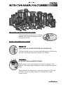 2
2
-
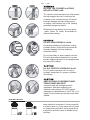 3
3
-
 4
4
-
 5
5
-
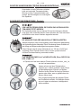 6
6
-
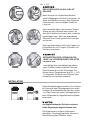 7
7
-
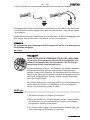 8
8
-
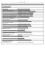 9
9
-
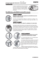 10
10
-
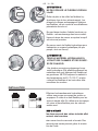 11
11
-
 12
12
-
 13
13
-
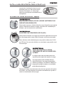 14
14
-
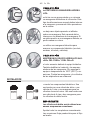 15
15
-
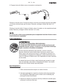 16
16
-
 17
17
-
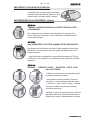 18
18
-
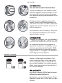 19
19
-
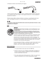 20
20
-
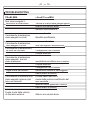 21
21
-
 22
22


En otros idiomas
- français: Simplex RDA1010 Manuel utilisateur
- italiano: Simplex RDA1010 Manuale utente
- English: Simplex RDA1010 User manual
- Deutsch: Simplex RDA1010 Benutzerhandbuch


