
Installation & Start-Up Manual
Generating Set
EAC
Copyright © Briggs & Stratton Corporation
Milwaukee, WI, USA. All rights reserved.
80010732
Revision ( A )

2
Thank you for purchasing this quality-built Briggs & Stratton® generating set. We are pleased that you’ve placed
your confidence in the Briggs & Stratton brand. When operated and maintained according to the instructions in the
operator’s manual, your generating set will provide many years of dependable service.
This manual contains safety information to make you aware of the hazards and risks associated with residential
generating set systems and how to avoid them. This generating set system is designed and intended only for
use as an optional system that provides an alternate source of electric power and to serve loads such as heating,
refrigeration systems, and communication systems that, when stopped during any power outage, could cause
discomfort or inconvenience. Save these original instructions for future reference.
This generating set system requires professional installation before use. The installer should follow the
instructions completely.
Where to Find Us
You never have to look far to find Briggs & Stratton support and service for your generating set. There are many
Briggs & Stratton authorized service providers worldwide who provide quality service. You can also contact Briggs
& Stratton Customer Service by phone at 800-732-2989 between 8:00 AM and 5:00 PM CT., or by e-mail at
[email protected], or click on Find a Dealer at BRIGGSandSTRATTON.COM, which provides a list
of authorized dealers.
For Future Reference
Please fill out the information below and keep with your receipt to assist in unit identification for future purchase
issues.
Date of Purchase
Generating set
Model Number
Model Revision
Serial Number
Engine
Model Number
Serial Number
Original Instructions (English)

3
Table of Contents
Important Safety Instructions .....................4
Installation .....................................7
Equipment Description .................................... 7
Owner Responsibilities .................................... 7
Installing Dealer/Contractor Responsibilities................... 7
Cold Weather Kit ......................................... 7
Unpacking Precautions .................................... 7
Delivery Inspection ....................................... 7
Shipment Contents ....................................... 8
Generating Set Placement ................................. 9
Placement of Standby Generating set to REDUCE THE RISK OF
CARBON MONOXIDE POISONING ........................ 10
Other General Location Guidelines ......................... 11
Electrical and Fuel Inlet Locations .......................... 14
Lifting the Generating Set ................................. 15
Concrete Anchoring of Unit................................ 15
Access Ports ........................................... 16
The Gaseous Fuel System ................................ 18
Fuel Factors ............................................ 19
Fuel Pressure........................................... 19
Power Loss ............................................ 19
Fuel Pipe Sizing......................................... 19
Fuel Consumption . . . . . . . . . . . . . . . . . . . . . . . . . . . . . . . . . . . . . . . 19
Fuel Conversion......................................... 20
System Connectors...................................... 21
Generating Set AC Connection System ..................... 22
Grounding the Generating Set ............................. 23
Utility Circuit Connection.................................. 23
Transfer Switch Communication ........................... 23
System Control Panel .................................... 24
Final Installation Considerations ........................... 29
Initial Start-up (No Load).................................. 30
Operation .....................................31
Automatic Operation Sequence ............................ 31
Setting Exercise Timer ................................... 31
Installation Inspection .................................... 32
Schematic / Wiring Diagrams.....................33

4
Save These Instructions
Important Safety Instructions
SAVE THESE INSTRUCTIONS - This manual
contains important instructions that should be followed
during installation and maintenance of the generating
set and batteries.
Safety Symbols and Meanings
The safety alert symbol indicates a potential
personal injury hazard. A signal word (DANGER,
WARNING, or CAUTION) is used with the alert symbol
to designate a degree or level of hazard seriousness.
A safety symbol may be used to represent the type of
hazard. The signal word NOTICE is used to address
practices not related to personal injury.
DANGER indicates a hazard which, if not avoided,
will result in death or serious injury.
WARNING indicates a hazard which, if not avoided,
could result in death or serious injury.
CAUTION indicates a hazard which, if not avoided,
could result in minor or moderate injury.
NOTICE addresses practices not related to personal
injury.
The manufacturer cannot possibly anticipate every
possible circumstance that might involve a hazard.
The warnings in this manual, and the tags and decals
affixed to the unit are, therefore, not all-inclusive.
If you use a procedure, work method or operating
technique that the manufacturer does not specifically
recommend, you must satisfy yourself that it is safe
for you and others. You must also make sure that the
procedure, work method or operating technique that
you choose does not render the generating set system
unsafe.
WARNING Running engine gives off carbon
monoxide, an odorless, colorless, poison gas.
Breathing carbon monoxide could result in
death, serious injury, headache, fatigue,
dizziness, vomiting, confusion, seizures,
nausea or fainting.
• Operate this product ONLY outdoors in an area that
will not accumulate deadly exhaust gas.
• Keep exhaust gas away from any windows, doors,
ventilation intakes, soffit vents, crawl spaces, open
garage doors or other openings that can allow
exhaust gas to enter inside or be drawn into a
potentially occupied building or structure.
• Carbon monoxide detector(s) MUST be installed
and maintained indoors according to the
manufacturer’s instructions/recommendations.
Smoke alarms cannot detect carbon monoxide gas.
WARNING Storage batteries give off explosive
hydrogen gas during recharging.
Slightest spark will ignite
hydrogen and cause explosion,
resulting in death and/or serious
injury.
Battery electrolyte fluid contains
acid and is extremely caustic.
Contact with battery
contents could cause severe
chemical burns.
A battery presents a risk of
electrical shock and high short
circuit current.
• DO NOT dispose of battery in a fire. Recycle
battery.
• DO NOT allow any open flame, spark, heat, or
lit cigarette during and for several minutes after
charging a battery.
• DO NOT open or mutilate the battery.
• Wear protective goggles, rubber apron, rubber
boots and rubber gloves.
• Remove watches, rings, or other metal objects.
• Use tools having insulated handles.
NOTICE Only qualified, licensed electricians should
attempt installation of this equipment, which must
strictly comply with applicable codes, standards and
regulations.
Fire
Toxic Fumes
Explosive Pressure
Lift Hazard Read Manual
Chemical BurnAuto Start
Hot SurfaceRotating Parts
Electrical ShockExplosion

5
WARNING Generating set produces hazardous
voltage.
Failure to properly ground generating set
could result in electrocution.
Failure to isolate generating set from utility
power could result in death or serious injury
to electric utility workers due to backfeed of
electrical energy.
• Electrical system must meet current requirements
when generating set is installed. This includes the
RCD in distribution panel.
• DO NOT touch bare wires or bare receptacles.
• DO NOT use generating set with electrical cords
which are worn, frayed, bare or otherwise damaged.
• DO NOT handle generating set or electrical cords
while standing in water, while barefoot, or while
hands or feet are wet.
• If you must work around a unit while it is operating,
stand on an insulated dry surface to reduce the risk
of a shock hazard.
• DO NOT allow unqualified persons or children to
operate or service generating set.
• In case of an accident caused by electrical shock,
immediately shut down the source of electrical
power and contact the local authorities. Avoid
direct contact with the victim.
• Despite the safe design of the generating set,
operating this equipment imprudently, neglecting its
maintenance or being careless could cause possible
injury or death.
• Remain alert at all times while working on this
equipment. Never work on the equipment when you
are physically or mentally fatigued.
• Before performing any maintenance on the
generating set, disconnect the battery cable
indicated by a NEGATIVE, NEG or (-) first. When
finished, reconnect that cable last.
• After your system is installed, the generating set
may crank and start without warning any time there
is a power failure. To prevent possible injury, always
set the generating set’s system switch to OFF,
remove the service disconnect from the disconnect
box AND remove the 15 Amp fuse BEFORE
working on the equipment.
WARNING Propane and Natural Gas are
extremely flammable and explosive,
which could cause burns, fire or
explosion resulting in death and/or
serious injury.
• Install the fuel supply system according applicable
fuel-gas codes.
• Before placing the generating set into service, the
fuel system lines must be properly purged and leak
tested.
• After the generating set is installed, you should
inspect the fuel system periodically.
• NO leakage is permitted.
• DO NOT operate engine if smell of fuel is present or
other explosive conditions exist.
• DO NOT smoke around the generating set. Wipe
up any oil spills immediately. Ensure that no
combustible materials are left in the generating set
compartment. Keep the area near the generating set
clean and free of debris.
WARNING Hazardous Voltage - Contact with
power lines could cause electric shock
or burns, resulting in death or serious
injury.
Lifting Hazard / Heavy Object - Could
result in serious injury.
• If lifting or hoisting equipment is used, DO NOT
contact any power lines.
• DO NOT lift or move generating set without
assistance.
• Use lifting pipes as described in Lifting the
Generating Set.
• DO NOT lift unit by roof as damage to generating
set will occur.

6
NOTICE Improper treatment of generating set could
damage it and shorten its life.
• Use generating set only for intended uses.
• If you have questions about intended use, contact
your authorized dealer.
• Operate generating set only on level surfaces.
• Adequate, unobstructed flow of cooling and
ventilating air is critical to correct generating set
operation.
• The access panels/doors must be installed
whenever the unit is running.
• DO NOT expose generating set to excessive
moisture, dust, dirt, or corrosive vapors.
• Remain alert at all times while working on this
equipment. Never work on the equipment when you
are physically or mentally fatigued.
• DO NOT start engine with air cleaner or air cleaner
cover removed.
• DO NOT insert any objects through cooling slots.
• DO NOT use the generating set or any of its parts as
a step. Stepping on the unit could cause stress and
break parts. This may result in dangerous operating
conditions from leaking exhaust gases, fuel leakage,
oil leakage, etc.
• If connected devices overheat, turn them off and
disconnect them from generating set.
Shut off generating set
and contact an authorized dealer
if
- electrical output is lost;
- equipment sparks, smokes, or emits flames;
- unit vibrates excessively;
- unit makes unusual noises.
WARNING Starter and other rotating parts could
entangle hands, hair, clothing, or accessories
resulting in serious injury.
• NEVER operate generating set without protective
housings, covers, or guards in place.
• DO NOT wear loose clothing, jewelry or anything
that could be caught in the starter or other rotating
parts.
• Tie up long hair and remove jewelry.
• Before servicing, remove 15 Amp fuse from control
panel and disconnect Negative (NEG or -) battery
cable.
WARNING
Exhaust heat/gases could ignite
combustibles or structures resulting in
death and/or serious injury. Contact with
muffler area could cause burns resulting
in serious injury.
• DO NOT touch hot parts and AVOID hot exhaust
gases.
• Allow equipment to cool before touching.
• Exhaust outlet side of weatherproof enclosure must
have at least 1.5 m minimum clearance from any
structure, shrubs, trees or any kind of vegetation.
• Weatherproof enclosure must be at least 1.5 m
from windows, doors, any wall opening, shrubs or
vegetation over 30.5 cm in height.
• Weatherproof enclosure must have a minimum
of 1.5 m overhead clearance from any structure,
overhang or trees.
• DO NOT place weatherproof enclosure under a
deck or other type of structure that may confine
airflow.
• Use only flexible fuel line provided. Connect
provided fuel line to generating set, DO NOT use
with or substitute any other flexible fuel line.
• Smoke detector(s) MUST be installed and
maintained indoors according to the manufacturer’s
instructions/recommendations. Carbon monoxide
alarms cannot detect smoke.
• Keep at least minimum distances shown in General
Location Guidelines to insure for proper generating
set cooling and maintenance clearances.
• To use or operate the engine on any forest-covered,
brush-covered, or grass-covered land, contact the
original equipment manufacturer, retailer, or dealer
to obtain a spark arrester designed for the exhaust
system installed on this engine.
• Replacement parts must be the same and installed
in the same position as the original parts.
CAUTION Installing the 15 Amp fuse could cause
the engine to start at any time without warning
resulting in minor or moderate injury.
• Observe that the 15 Amp fuse has been removed
from the control panel for shipping.
• DO NOT install this fuse until all plumbing and wiring
has been completed and inspected.
CAUTION Excessively high operating speeds
could result in minor injury.
Excessively low speeds impose a heavy load on
generating set.
• DO NOT tamper with governed speed. Generating
set supplies correct rated frequency and voltage
when running at governed speed.
• DO NOT modify generating set in any way.

7
Installation
Equipment Description
This product is intended for use as an optional system
which provides an alternate source of electric power
and to serve loads such as heating, refrigeration
systems, and communication systems that, when
stopped during any power outage, could cause
discomfort or inconvenience.
Every effort has been made to ensure that information
in this manual is accurate and current. However, we
reserve the right to change, alter, or otherwise improve
the product and this document at any time without prior
notice.
Only current licensed electrical and plumbing
professionals should attempt generating set
system installations. Installations must strictly
comply with all applicable codes, industry
standards and regulations.
Owner Responsibilities
• Read and follow the instructions given in the
operator’s manual.
• Follow a regular schedule in maintaining, caring
for and using your generating set, as specified in
the operator’s manual.
• Carbon monoxide detector(s) MUST be installed
and maintained indoors according to the
manufacturer’s instructions/recommendations.
Smoke alarms cannot detect carbon monoxide
gas.
• Smoke detector(s) MUST be installed and
maintained indoors according to the manufacturer’s
instructions/ recommendations. Carbon monoxide
alarms cannot detect smoke.
If you have questions about intended use,
Installing Dealer/Contractor
Responsibilities
• Read and observe the safety rules.
• Read and follow the instructions given in this
installation and start-up manual.
• Installation must strictly comply with all applicable
codes, industry standards, laws, and regulations.
• Allow sufficient room on all sides of the generating
set for maintenance and servicing.
Cold Weather Kit
If operating the generating set below -1°C, it is
HIGHLY RECOMMENDED that a Cold Weather Kit be
installed on the unit.
FOR 6kVA MODELS, USE COLD WEATHER KIT:
6262 (includes two oil warmers and one battery
warmer)
FOR 8kVA MODELS, USE COLD WEATHER KIT:
6030A (includes one oil warmer and one battery
warmer)
These items are available at your local servicing
dealer.
For cold weather areas below -18°C it is also
recommended that a BCI, Size 24F, wet lead-acid
battery be used of 800 CCA minimum.
Unpacking Precautions
The unit is shipped ready for installation. Avoid
damage from dropping, bumping, collision, etc. Store
and unpack carton with the proper side up, as noted
on the shipping carton.
Delivery Inspection
After removing the carton, carefully inspect the
generating set for any damage that may have occurred
during shipment.
If loss or damage is noted at time of delivery, have
the person(s) making delivery note all damage on the
freight bill and affix his signature under the consignor’s
memo of loss or damage. If loss or damage is noted
after delivery, separate the damaged materials
and contact the carrier for claim procedures. Parts
damaged in shipping are not warranted.
-1°C

8
Shipment Contents
The generating set system is supplied with:
• Oil (5W30 Synthetic)
• Flexible steel fuel line
• Installation and start-up manual
• Operator’s manual
• Spare access keys
• Spare 15 Amp ATO-type fuse
Not included:
• Carbon monoxide detector(s)
• Smoke detector(s)
• Starting battery
• Connecting wire and conduit
• Fuel supply valves/plumbing
• Crane, lifting straps, chains or cables
• Two 1.2 meter lengths of 25 mm pipe, 3.3 mm
minimum thickness (NOT conduit)
• Hole punches for 1.6 mm steel
• Torque screwdriver, 0.5 to 5 Nm range
• Voltage/frequency meter
• Various special tools and equipment
• Remote wireless monitor (OPTIONAL)
• Antenna (OPTIONAL)

9
Generating Set Placement
Before installing generating set, consult with owner
and convey the following requirements, which must be
satisfied before the installation is complete.
There are two equally important safety concerns in
regards to carbon monoxide poisoning and fire. There
are also several general location guidelines that must be
met before the installation in considered complete.
Exhaust Side of the Generating Set
A - Exhaust outlet side of weatherproof enclosure
A
WARNING Running engine gives off carbon
monoxide, an odorless, colorless, poison gas.
Breathing carbon monoxide could result
in death serious injury, headache, fatigue,
dizziness, vomiting, confusion, seizures,
nausea or fainting.
• Operate this product ONLY outdoors in an area that
will not accumulate deadly exhaust gas.
• Keep exhaust gas away from any windows, doors,
ventilation intakes, soffit vents, crawl spaces, open
garage doors or other openings that can allow
exhaust gas to enter inside or be drawn into a
potentially occupied building or structure.
• Carbon monoxide detector(s) MUST be installed
and maintained indoors according to the
manufacturer’s instructions/recommendations.
Smoke alarms cannot detect carbon monoxide gas.

10
All fossil fuel burning equipment, such as standby
generating sets, contains carbon monoxide (CO) gas
in the engine exhaust. CO gas is odorless, colorless
and tasteless and is unlikely to be noticed until a
person is overcome. CO gas can kill you so it is
required that the following is included as part of the
installation:
• Install generating set outdoors in an area that will
not accumulate deadly exhaust gas.
• DO NOT install generating set where exhaust gas
could accumulate and enter inside or be drawn
into a potentially occupied building or structure.
• It may be required to have a Carbon Monoxide
(CO) detector in operating condition in your home.
Carbon monoxide detector(s) (A) MUST be
installed and maintained indoors according to the
manufacturer’s instructions / recommendations.
A CO monitor is an electric device that detects
hazardous levels of CO. When there is a buildup
of CO, the monitor will alert the occupants by
flashing visual indicator light and alarm. Smoke
alarms cannot detect CO gas.
• Your neighbor(s) home may be exposed to the
engine exhaust from your standby generating
set and must be considered when installing your
standby generating set.
• Ensure exhaust gas is kept away from:
B - windows
C - doors
D - ventilation intakes
E - soffit vents
F - garage doors
G - crawl spaces or other openings that can allow
exhaust gas to enter inside or be drawn into a
potentially occupied building or structure.
Placement of Standby Generating set to REDUCE THE RISK OF CARBON MONOXIDE
POISONING
The arrows in the figure below point to POTENTIAL points of entry for Carbon
Monoxide Gas.
A
F
C
D
B
E
G
F
C
D
B
E
G
NOTICE This Section is for Carbon Monoxide Hazard Safety Placement Only. Satisfying the standby generating
set placement, for the Carbon Monoxide hazard, does not guarantee that Fire Safety Placement requirements are
met. Please refer to Page 14 for Fire Hazard Safety Placement requirements.

11
• Direct the standby generating set exhaust away
from or parallel to the building or structure. DO
NOT direct the generating set exhaust towards a
potentially occupied building, structure, windows,
doors, ventilation intakes, soffit vents, crawl
spaces, open garage doors or other openings
where exhaust gas could accumulate and enter
inside or be drawn into potentially occupied
building or structure.
• DO NOT place standby generating set in any area
where leaves or debris normally accumulates.
Position standby generating set in an area where
winds will carry the exhaust gas away from any
potentially occupied building or structure.
Other General Location Guidelines
• Place the generating set in a prepared location
that is flat and has provisions for water drainage.
• Install the generating set in a location where sump
pump discharge, rain gutter downspouts, roof run-
off, landscape irrigation, or water sprinklers will
not flood the unit or spray the enclosure and enter
any air inlet or outlet openings.
• Install the generating set where it will not affect
or obstruct and services including covered,
concealed and underground, such as telephone,
electric, fuel (natural gas/ LPG vapor), irrigation,
air conditioning, cable, septic, sewer, well and so
forth.
• Install the generating set where leaves, grass,
snow, etc. will not obstruct air inlet and outlet
openings. If prevailing winds will cause blowing or
drifting, you may need to construct a windbreak to
protect the unit.
WARNING
Exhaust heat/gases could ignite
combustibles or structures resulting in death
or serious injury.
• Exhaust outlet side of weatherproof enclosure must
have at least 1.5 m minimum clearance from any
structure, shrubs, trees or any kind of vegetation.
• Generating set’s weatherproof enclosure must be at
least 1.5 m from windows, doors, any wall opening,
shrubs or vegetation over 30.5 cm in height.
• Generating set’s weatherproof enclosure must have
a minimum of 1.5 m overhead clearance from any
structure, overhang or trees.
• DO NOT place weatherproof enclosure under a
deck or other type of structure that may confine
airflow.
• Use only flexible fuel line provided. Connect
provided fuel line to generator, DO NOT use with or
substitute any other flexible fuel line.
• Smoke detector(s) MUST be installed and
maintained indoors according to the manufacturer’s
instructions/recommendations. Carbon monoxide
alarms cannot detect smoke.
• DO NOT place weatherproof enclosure in manner
other than shown in illustrations.
STANDBY
GENERATOR
ENGINE
EXHAUST

12
Examples of standby generating set locations to
reduce the risk of fire:
Vertical Clearances
Structure
Center of Exhaust Panel
Standby
Exhaust
Direction
1.5 m
1.5 m
B
C
B
C
Legend for Generating Set Locations to reduce
the risk of fire:
A - Generator set’s weatherproof enclosure must
be at least 1.5 m from windows, doors, any wall
opening, shrubs, or vegetation over 30.5 cm in
height.
B - Exhaust outlet side of weatherproof enclosure
must have at least 1.5 m minimum clearance from
any structure, overhang or trees.
C - Generating set’s weatherproof enclosure must
have a minimum of 1.5 m overhead clearance
from any structure, overhang, or trees.
NOTICE DO NOT place weatherproof enclosure under
a deck or other type of covered structure that may
confine airflow.

13
Generating Set Installations
A
A
A
A
A
A
A
Standby
Standby
Standby
Standby
1.5 m
1.5 m
1.5 m
1.5 m
1.5 m
1.5 m
1.5 m
Exhaust
Direction
Exhaust
Direction
Exhaust
Direction
Exhaust
Direction
45.7 cm min.45.7 cm min.
B
B
B
B
45.7 cm
NOTICE The figures below show the minimum installation distances allowed to structures and items listed in the
legend.
Legend for Generating Set Locations to reduce
the risk of fire:
A - Generator set’s weatherproof enclosure
must be at least 1.5 m from windows, doors,
any wall opening, shrubs, or vegetation over
30.5 cm in height.
B - Exhaust outlet side of weatherproof
enclosure must have at least 1.5 m minimum
clearance from any structure, overhang or
trees.
C - Generating set’s weatherproof enclosure must
have a minimum of 1.5 m overhead clearance from
any structure, overhang, or trees.
NOTICE DO NOT place weatherproof enclosure under a
deck or other type of covered structure that may confine
airflow.

14
Electrical and Fuel Inlet Locations
The 19 mm N.P.T. fuel inlet connector (A) and electrical
inlet location (B) is shown below.
A
B

15
Lifting the Generating Set
The generating set weighs more than 150 kg. Proper
tools, equipment and qualified personnel should
be used in all phases of handling and moving the
generating set.
Two 1.2 m lengths of size 6 scaffold tube (33.7 mm OD
x 25 mm ID to EN39) or equivalent are required to lift
the generating set (A). Insert these tubes through the
lifting holes (B) located near the unit’s base. Position
the tubes so that equal length’s protrude from each
side.
You may also lift the unit using a “hook and hoist”
method attached to the lifting pipes, provided that you
use a spreader bar to ensure that the chains or cables
DO NOT touch the generating set’s roof.
In areas determined to be hurricane prone, it is
recommended to anchor the standby generating set to
concrete. The concrete anchors must be rated to hold
800 lbs ( kg). There are three (C) locations in the base
of the generating set in which to anchor the unit.
Concrete Anchoring of Unit
NOTICE Unless mandated by code, a concrete
slab is not required.
C
C
C
A
B
WARNING Hazardous Voltage - Contact with
power lines could cause electric shock
or burns, resulting in death or serious
injury.
Lifting Hazard / Heavy Object - Could
result in serious injury.
• If lifting or hoisting equipment is used, DO NOT
contact any power lines.
• DO NOT lift or move generating set without
assistance.
• Use lifting pipes as described in Lifting the
Generating Set.
• DO NOT lift unit by roof as damage to generating
set will occur.

16
Access Ports
The generating set is equipped with an enclosure that
has several access panels, as shown.
NOTICE The generating set roof must be removed to
gain access to the front panel.
(A) Front Panel that is used to access:
• Battery Compartment
• Engine Oil Drain Hose
• Engine Oil Filter
• Engine Valve Cover
• Spark Plugs
Each generating set is shipped with a set of identical
keys.
A

17
To remove roof:
1. Remove the five screws (A) that secure the roof
to the unit.
2. Carefully lift and remove roof from unit.
To remove front panel:
1. Remove the two screws (B) that secure the panel to
the unit.
2. Lift and flex panel outward and off base. Use
caution not to damage the battery box (C).
To secure front panel:
1. Place panel in unit.
2. Secure the panel with two screws.
A
C
B

18
The Gaseous Fuel System
The information below is provided to assist
gaseous fuel system technicians in planning
installations. In no way should this information
be interpreted to override applicable fuel gas
codes. Consult with your local fuel supplier or Fire
Marshall if questions or problems arise.
TO THE INSTALLER: Consult with the generating
set owner(s) and convey any technical
considerations that might affect their installation
plans before applying these general guidelines.
The following general rules apply to gaseous fuel
system piping:
NOTICE The supplied flexible
steel fuel line
is not to be
installed underground or in contact with the ground.
• The entire
flexible
steel fuel line must be visible for
periodic inspection and must not be concealed
within nor contact nor run through any wall, floor,
or partition.
• The piping should be of a material that conforms
to federal and local codes, rigidly mounted and
protected against vibration.
• Piping should be protected from physical
damage where it passes through flower beds,
shrub beds, and other cultivated areas where
damage could occur.
NOTICE The illustration is representative of a typical
installation. Your installation may differ.
• Install the
flexible
steel fuel line (B) (supplied)
between the generating set fuel inlet port (A)
and rigid piping to prevent thermal expansion,
contraction, or any standby movement from
causing excessive stress on the piping material.
• A union (C) or flanged connection shall be
provided downstream to permit removal of
standby.
• A manometer port should be provided (D). A
digital manometer, P/N 19495, is available at
your Briggs & Stratton service center. When the
initial test runs are completed, the manometer
is removed and the port is plugged. The
manometer port permits temporary installation of
a manometer to ensure that the engine receives
the correct fuel pressure to operate efficiently
throughout its operating range.
• Where the formation of hydrates or ice is known
to occur, piping should be protected against
freezing. The termination of hard piping should
include a sediment trap (F) where condensate is
not likely to freeze.
• A minimum of one accessible, approved manual
shutoff valve (E) shall be installed in the fuel
supply line within 180 cm of the generating set.
• A manual fuel shut-off valve should be installed
in the interior of the building.
• Where local conditions include earthquake,
tornado, unstable ground, or flood hazards,
special consideration shall be given to increase
strength and flexibility of piping supports and
connections.
• Piping must be of the correct size to maintain
the required supply pressures and volume flow
under varying generating set load conditions
with all gas appliances connected to the fuel
system turned on and operating.
• Apply thread sealant approved for use with NG/
LPG on all male threads only per sealant
manufacturer’s instructions and applicable
codes and standards.
NOTICE Keep thread sealant out of the gas
piping to prevent component part damage.
• Installed piping must be properly purged and
leak tested, in accordance with applicable codes
and standards.
WARNING
Propane and Natural Gas are
extremely flammable and explosive,
which could cause burns, fire or
explosion resulting in death or serious
injury.
• LP gas is heavier than air and will settle in low
areas.
• Natural gas is lighter than air and will collect in high
areas.
• The slightest spark could ignite these fuels and
cause an explosion.
• DO NOT light a cigarette or smoke.
WARNING Propane and Natural Gas are
extremely flammable and explosive,
which could cause burns, fire or
explosion resulting in death or serious
injury.
• Before placing the generating set into service, the
fuel system lines must be properly purged and leak
tested.
• No leakage is permitted.
D
A
F
E
B
C

19
Fuel Consumption
Estimated fuel supply requirements for natural gas and
LP vapor fuels are shown below.
LP Vapor (Propane)
8 kVA 6 kVA
Full Load
Cu Ft/Hr 65.6 56.4
Gal/Hr
(liquid)
1.82 1.57
BTU/Hr 164,000 141,000
m³ /Hr 1.86 1.60
1/2 Load
Cu Ft/Hr 42.8 37.6
Gal/Hr
(liquid)
1.18 1.04
BTU/Hr 107,000 94,000
m³ /Hr 1.21 1.06
Exercise
Cu Ft/Hr 23.6 20
Gal/Hr
(liquid)
0.65 0.56
BTU/Hr 59,000 50,000
m³ /Hr 0.67 0.57
Natural Gas
6.5 kVA 5.4 kVA
Full
Load
Cu Ft/ Hr 169 121
BTU / Hr 169,000 121,000
m³ /Hr 4.79 3.43
1/2 Load
Cu Ft/ Hr 111 94
BTU / Hr 111,000 94,000
m³ /Hr 3.14 2.66
Exercise
Cu Ft/ Hr 60 53
BTU / Hr 60,000 53,000
m³ /Hr 1.70 1.50
Fuel Factors
An important consideration affecting the entire
installation is the type of fuel used by your generator.
The system was factory tested and adjusted
using natural gas, but can be converted to use LP
vapor. For proper engine function, factors that are
inherent to each of these fuels, your location and the
duration of possible utility interruptions are important
considerations in the following fuel guidelines:
• Use clean, dry fuel, free of moisture or any
particulate material. Using fuels outside the
following recommended values may cause
performance problems.
• In engines set up to run on propane (LP),
commercial grade HD5 propane with a minimum
fuel energy of 2500 BTUs/ft3 with maximum
propylene content of 5% and butane and heavier
gas content of 2.5% and minimum propane
content of 90% is required.
Natural gas rating will depend on specific fuel but
typical derates are between 10 to 20% off the LP gas
rating.
Natural gas or LP engines are certified to operate on
natural or liquid propane gas. The emissions control
system for this engine is EM (Engine Modifications).
Fuel Pressure
Both LP vapor and natural gas fuel supply pressure
at the generator’s fuel inlet port should be between
the following levels at full load with all gas appliances
turned on
and operating.
• NG is 5-7” W.C.
• LP is 11-14” W.C.
Ensure that all gas line shutoff valves are OPEN and
that adequate fuel pressure is available whenever
automatic operation is desired.
Power Loss
Air density is less at high altitudes, resulting in less
available engine power. Specifically, engine power
will decrease 3.5% for each 300 meters (1,000 feet)
above sea level and 1% for each 5.6°C (10° F) above
25°C (77°F). Make sure you and your installer consider
these factors when determining total generator load.
Fuel Pipe Sizing
There are numerous on-line or otherwise-published
references for fuel pip sizing. For example, NFPA
54-Natural Fuel Gas Code, 2006 (Item #: 320-6031-06)
is a common resource.
The installer should consider the specific gravity of gas
and compensate for a nominal amount of restriction
from bends, fittings, etc. If an unusual number of
fittings, bends, or other restrictions are used, refer to
federal and local codes for guidance.

20
Fuel Conversion
The engine of your generating set system is factory
calibrated to run on natural gas (NG). It may also be
operated on liquefied petroleum (LP) vapor.
To configure the 6 kVA fuel system for LP use:
1. Set generating set system switch to OFF.
2. Remove 15 Amp fuse from control panel.
3. Remove roof and side panels.
4. Change main jet in fuel mixer following
instructions provided in LP Conversion Kit.
5. Replace side panels and roof.
6. Reinstall 15 Amp fuse in control panel.
7. Set generating set system switch to AUTO.
The system is now ready to operate automatically using
LP vapor fuel.
To configure the 8 kVA fuel system for LP use:
1. Set generating set system switch to OFF.
2. Remove 15 Amp fuse from control panel.
3. Open oil fill access panel.
4. Connect the fuel select solenoid by joining the
two-pin electrical connector.
5. Reinstall 15 Amp fuse in control panel.
6. Set generating set system switch to AUTO.
7. Close access panels.
The system is now ready to operate automatically using
LP vapor fuel.

21
System Connectors
Low Voltage connections to signal fault contacts, transfer switch communication and auxiliary 12VDC power
are made via a field connection terminal block in control board area. Compare this illustration with your
generating set to familiarize yourself with the location of these connections.
A - Two Pin Terminal Block — Used to connect utility
230 VAC from fuse block in ATS to the control
board. Connect only one wire per terminal.
B - Fault Contacts — Use NO, COM and NC to hook
up a siren, light, etc. to alert you in case of a fault.
Contacts reverse state (NO goes to NC and vice
versa) upon a fault condition.
C - Transfer Switch Communication (TxRx and
TxRx GND) — Connect to transfer switch control
board for communication interface using 18AWG
twisted pair wire. (Not applicable with all transfer
switches.)
D - +LED and GND Connection — Not required for
optional wireless monitor. Available for optional
hardwired remote system status panel accessory,
#6154.
E - Eight Pin Terminal Block — Used to connect
signal wires to the control board. Connect only
one wire per terminal.
F - Power Connection (Line 1 and Line 2) — Power
connection to transfer switch.
G - Neutral and/or Ground Connection — Connect
to transfer switch neutral and ground
• For power output connection:
(Line 1, Line 2, and Ground), 300V, 10 AWG copper wire, or 300V, 8 AWG aluminum wire.
• For utility circuit connection (Utility A and Utility B) use #14 AWG minimum 300 volt wire.
• For transfer switch communication use #18 AWG twisted pair conductors, no greater than 61M in length, 300 volt wire.
• When connecting to the terminal block, fasten only one wire to each connector screw.
• Torque terminal block screws to 0.49 Newton meter.
• Torque circuit breaker connections to 5 Newton meter.
1
2
3
4
5
6
7
8
UTILITY 1
UTILITY 2
L1
L2
E
A
G
[
[
[
B C
D
F

22
Generating Set AC Connection System
A single-phase, three-wire AC connection system
is used in the generating set. The stator assembly
consists of a pair of stationary windings with two leads
brought out of each winding. A complete schematic
and wiring diagram can be found later in this manual.
33
230V
11
22
44
1144 0
Power Winding
Circuit
Breaker
Circuit
Breaker
GroundLine 2 Line 1

23
Grounding the Generating Set
Ground the generating set per applicable codes,
standards, and regulations. If the installation includes a
lightning protection system, then consider whether the
generator needs to be incorporated into this system.
The generating set PE lug is located inside the control
panel door under the circuit breaker cover.
Utility Circuit Connection
“230V Utility” leads must be routed in conduit. The
“230V Utility” leads deliver power to the generating
set’s circuit board, optional battery warmer and
optional oil warmer. This power also charges the
battery. When power on these leads is lost, the
generating set will start.
Using provided 2 pin connector plug and installer-
supplied minimum 300V, 2.5 mm² copper wire,
connect each control circuit terminal in the generating
set to the two-amp fuse terminals in the automatic
transfer switch.
When making connections, obey wire type and torque
specifications printed on the circuit breaker and
neutral/ground connector.
Transfer Switch Communication
(Units with ACCM II or later transfer switch only)
Using 2.5 mm² twisted pair conductors, no greater than
60 m in length, connect Tx Rx and Tx Rx GND from
the generating set terminal block (A) to GND and T/R
on the transfer switch control board (B).
4
5
A
B

24
System Control Panel
The generating set control panel, located inside the
generating set housing, is shown below.
Brief descriptions of the controls used during
installation are:
The generating set control board, located inside the
generating set, under the roof, is shown below. Brief
descriptions of the controls used during installation are:
A - Menu/Programming Navigation Buttons — See
Menu section for details
B - USB Port — Authorized Dealer Service Use Only
C - Generating set Operation Control Buttons —
•“AUTO” Normal operating position. Press and
hold button to put unit into Automatic mode. If
an utility power outage is sensed, the system
will start the generating set. When utility power
is restored, auto lets the engine stabilize internal
waits for the next utility outage.
•“OFF”
unit from starting, and resets any detected faults.
OFF must be pressed and held for more than 5
seconds in order to reset service codes.
•“MANUAL” Used to manually start the generating
set.
“AUTO” LED — LED will light when unit is placed
into Auto mode. LED will blink if exercise cycle is
not set or set to OFF.
D - 15 Amp Fuse — Protects the generating set DC
control circuits. If the fuse has ‘blown’ (melted
open) or was removed, the engine cannot crank
or start. Replace the fuse using only an identical
ATO 15 Amp fuse. One spare fuse is supplied
with the unit.
E - Cover — This protective cover must be opened to
access the fuse and the USB port.
F - Digital Display — Displays generating set mode,
menu options, service codes, and service engine
indicators
More information may be found in Controls in the
operator’s manual.
A
B
C
F
E
D

25
Menu
MENU
ENTER THE MENU (VIEW SETTINGS)
PRESS TO CONFIRM SELECTION WHEN PROGRAMMING.
ESCAPE (EXIT) RETURN TO LAST MENU ITEM
RIGHT ARROW
TOGGLE THROUGH MENU OPTIONS
SETTING SYSTEM PARAMETERS
LEFT ARROW
TOGGLE THROUGH MENU OPTIONS
SETTING SYSTEM PARAMETERS
MANUAL MODE
USED TO MANUALLY START THE GENERATING SET. PRESS AND
HOLD BUTTON TO START THE GENERATING SET.
OFF
TURNS OFF RUNNING GENERATING SET, PREVENTS UNIT FROM
STARTING, AND RESETS ANY DETECTED FAULTS.
AUTOMATIC MODE
NORMAL OPERATING POSITION. PRESS AND HOLD BUTTON TO
PUT UNIT INTO AUTOMATIC MODE. IF A UTILITY POWER OUTAGE
IS SENSED, THE
SYSTEM WILL START THE Generating set. WHEN UTILITY POWER
IS RESTORED, AUTO LETS THE ENGINE STABILIZE INTERNAL
TEMPERATURES, SHUTS OFF THE Generating set, AND WAITS
FOR THE NEXT UTILITY POWER OUTAGE.
GENERAL
SET-UP
PRESS AND HOLD [ARROW LEFT AND ARROW RIGHT]
FOR THREE SECONDS TO ENTER THE PROGRAM
MODE.
ADVANCED
SETTINGS
PRESS AND HOLD [ARROW LEFT, ARROW RIGHT AND
ESC] FOR THREE SECONDS TO ENTER THE ADVANCED
SETTINGS MODE.
WIRELESS
LINK MODE
PRESS AND HOLD [MENU AND ESC] FOR THREE
SECONDS TO ENTER THE WIRELESS LINKING MODE.
The following chart shows the icons for the buttons that control the system control panel.
The following chart describes key sequences for accessing different programming modes;

26
General Set Up Screen
For general set up, press and hold the left arrow and right arrow for 3 seconds. Follow the prompts as
outlined below.
NOTE: Date and Time were set at the factory and stored in the control panel memory. The Exercise Cycle was
also set at the factory. The default exercise cycle occurs on Tuesdays, at 2:00 P.M. Central Standard Time. To
update or change these settings, follow the steps below.
IF DURING PROGRAMMING NO BUTTONS ARE PRESSED FOR 30 SECONDS,
THE CONTROL PANEL WILL AUTOMATICALLY EXIT THE PROGRAM MODE.
SET DATE
If set to OFF, display will read:
EXERCISE CYCLE OFF
or
YEAR
FLASHING
MONTH
FLASHING
DAY##
FLASHING
SET TIME
HOURS
FLASHING
MINUTES
FLASHING
AM/PM
FLASHING
or or or
or
or or or
or
or
or or or or
DAY OF WEEK
FLASHING
HOURS
FLASHING
MINUTES
FLASHING
AM/PM
FLASHING
SET EXERCISE
CYCLE
EVENT LOG
Display will scroll last service code event, date, time,
and ambient temperature of when the event occurred.
or
OFF

27
Control Panel Prompts
Automatic Mode
In Automatic Mode, the display screen will display via
scrolling text:
• Generating set READY - if the unit is in standby and
utility power is present.
• Generating set ON - if the unit is running and utility
power is not present.
• SERVICE CODE - if a system fault has been detected.
General System Parameters
To view general system parameters, press the MENU
button.
The following will scroll across the digital display and then
move to the next item:
• Run time
• Date
• Time
• Exercise Cycle date and start time
The user can press the LEFT ARROW or RIGHT ARROW at
any time to move to the next item.
The user can press ESCAPE to go back to Generating set
READY.
If no user inputs are made for 10 seconds after all the items
have been displayed, the control board will reset to
Generating set READY.
AUTOMATIC MODE
GENERATOR READY OR SERVICE CODE DESCRIPTION
(When Generator NOT Running - Auto Mode)
GENERATOR ON
(When Generator Running - Auto Mode)
(MENU)
RUN TIME
or
or
or
TIME
DATE
EXERCISE CYCLE

28
Advanced Settings Screen
Advanced setting parameters are preset at the factory for a typical installation. To view Advanced Settings items
and/or to change items, follow the instructions listed below.
NOTICE Advanced settings are critical to the operation of the unit. Careful consideration should be
taken when working in the Advanced Settings menu. Exercise caution when selecting and verifying
parameters for the generating set and region where the generating set is being operated. Confirm all
settings before operating the generating set for the first time.
Before setting the Advanced menu items, press the OFF button on the control panel. Then press and hold the left
arrow, right arrow, and escape key for 3 seconds. Follow the prompts as outlined below.
NOTICE In the Advanced Setting menu, a three button access code (left arrow, right arrow, and escape key
must be pressed once to enter the menu and again to change any setting. After each confirmation of a setting, the
selection will display solid for 2 seconds before moving to the next program item.
kVA
Hz
kVA
FLASHING
50/60 Hz
FLASHING
PHASE
SINGLE
or
THREE
FLASHING
VOLTS
VOLTS
FLASHING
SOFTWARE
VERSION DISPLAYED
or
or
or
or
or
or
or
or

29
Final Installation Considerations
Engine Oil
NOTICE Any attempt to crank or start the engine
before it has been properly serviced with the
recommended oil will result in equipment failure.
• Refer to Maintenance in the operator’s manual for oil
fill information.
• Damage to equipment resulting from failure to follow this
instruction will void engine and generating set warranty.
The engine is shipped from the factory pre-run and
filled with synthetic oil (API SJ/CF 5W-30). This allows
for system operation in a wide range of temperature
and climate conditions. Before starting the engine,
check oil level and ensure that engine is serviced as
described in Maintenance of the Operator’s Manual.
The use of synthetic oil does not alter the required oil
change intervals described in the Operator’s Manual.
For operation of temperatures below -1°C, the use of
fully synthetic oil (minimum API SJ) of viscosity 5W30
is required.
Battery
The installer must supply and install rechargeable
starting battery. The starting battery MUST conform to
the specifications shown below in the chart.
Battery
Specifications
Standard Cold Start
(less than
-1°C)
Volts 12 Volt DC 12 Volt DC
Amps (MIN) 540 CCA (cold
cranking amps)
800 CCA
(cold cranking
amps)
Construction Wet lead acid Wet lead acid
Terminal Type Top post type
battery
Top post type
battery
Dimensions
(MAX):
BCI size 26 or 51 BCI size 24F
Install the battery as described in Servicing the Battery
in the Maintenance section of the Operator’s Manual.
Always make sure the NEGATIVE cable is connected
last.
Use the supplied tie-down strap (A) to secure the
battery to the unit. Each end of the strap should be
attached to the existing tabs in the base of the unit.
Service Code Detection System
The generating set may have to run for long periods
of time with no operator present. For that reason, the
system is equipped with sensors that automatically
shut down the generating set in the event of potentially
damaging conditions, such as low oil pressure, high
temperature, over speed, and other conditions. Refer
to Service Code Detection System in the operator’s
manual for more detailed information.
A

30
Initial Start-up (No Load)
The unit has been set-up for NG operation at the
factory. Fuel conversion, if needed, must be completed
prior to performing these steps. See Fuel Conversion.
Before operating the generating set or placing it into
service, inspect the entire installation carefully. Then
begin testing the system without any electrical loads
connected, as follows:
1. Remove two screws (A) that secure the circuit
breaker cover to expose unit’s circuit breaker.
2. Connect an accurate frequency meter to line side
of generating set’s main circuit breaker.
3. Set generating set’s main circuit breaker to ON
(closed) position.
4. Install 15 Amp fuse in control board.
5. Press and hold MANUAL button on control board
for 3 seconds. Engine will start.
When the generating set is started for the very first
time, it will require that air in the gaseous fuel lines be
purged. This may take a few minutes.
6. Listen for unusual noises, vibration or other
indications of abnormal operation. Check for oil
leaks while engine runs.
7. Let engine warm up for about 5 minutes to allow
internal temperatures to stabilize.
8. Check generating set output at load side of circuit
breaker. Voltage should be 229 - 235 Volts,
frequency should be 52.0 - 52.5 Hz, at no load.
9. Push and hold OFF BUTTON on control board
until engine stops.
10. Reinstall control box cover.
L1
L2
1
2
3
4
5
6
7
8
UTILITY 1
UTILITY 2
A

31
Operation
Automatic Operation Sequence
The generating set’s control board constantly monitors
utility voltage. Should utility voltage drop below a
preset level, the control board will signal the engine to
crank and start.
When utility voltage is restored above a preset voltage
level, the engine is signaled to shut down.
The actual system operation is not adjustable and
is sequenced by sensors and timers on the control
board, as follows:
Utility Voltage Dropout Sensor
• This sensor monitors utility source voltage.
• If utility source voltage drops below about
70 percent of the nominal supply voltage, the
sensor energizes a 3 second timer. The timer is
used to ‘sense’ brown-outs.
• Once the timer has expired, the engine will crank
and start.
Utility Voltage Pickup Sensor
This sensor monitors utility power voltage. When utility
voltage is restored above 80 percent of the nominal
source voltage, a time delay starts timing and the
engine will go to engine cool-down.
Engine Cool-down Timer
When utility power is sensed and the load transfers to
the utility source, the engine will go into a cool down
period as described below:
• If the generating set has run for MORE than
5 minutes, once the utility transfer occurs, the
engine will continue to run for about 1 minute
before shutting down.
• If the generating set has run for LESS than 5
minutes, once the utility transfer occurs, the
engine will continue to run until 5 minutes has
elapsed before shutting down.
Setting Exercise Timer
The generating set is equipped with an exercise
timer. During the exercise period, the unit runs for
approximately 20 minutes and then shuts down.
Electrical load transfer DOES NOT occur during the
exercise cycle (unless an utility power outage occurs).
The generating set will only enter the exercise cycle if
the unit is in the AUTO mode and this exact procedure
is followed.
To set the exercise timer:
NOTICE The generating set is set with a default
exercise cycle setting of Tuesday at 2:00 PM, Central
Time. To change the cycle setting, proceed to the
following steps:
1. Choose the day and time you want your
generating set to exercise.
2. Press and hold the left arrow and right arrow
simultaneously for 3 seconds to enter the General
Set-Up program mode. See General Set-Up flow
chart in Menu Section.
3. Verify and/or set the time and date on the unit.
4. Go to the SET EXERCISE prompt and hit the “OK”
button.
NOTICE Items will flash until they are selected.
SELECT DAY: Use the left or right arrow to toggle
through the days of the week, Once the day is
selected, hit the “OK” button.
SELECT HOUR: Use the left or right arrow
to toggle through between 1 and 12. Choose
the hour of day you want the generating set to
exercise then hit the “OK” button.
SELECT MINUTE: Use the left of right arrow to
toggle between :00 and :59. Choose the minute
of the day you want the generating set to exercise
then hit the “OK” button.
SELECT AM/PM: Use the left of right arrow to
toggle between AM and PM. Once chosen, hit the
“OK” button.
NOTICE During the weekly exercise cycle, the
generating set will run for 20 minutes, but it will not
supply power to the home.
If you want to change the day and time the unit
exercises, simply perform the procedure again.
To turn off the generating set exercise cycle, go to
the OFF selection within the day of the week menu
and press OK. The display will then scroll: EXERCISE
CYCLE OFF.
CAUTION With the system switch set to AUTO,
the engine could crank and start at any
time without warning, resulting in minor or
moderate injury.
• To prevent possible injury that may be caused by
such sudden starts, always set the system switch to
OFF if performing maintenance on the system.
• Remove the 15 Amp fuse before working on or
around the generating set or transfer switch.

32
Installation Inspection
Before placing the generating set system into service,
inspect the entire installation carefully, utilizing the
Installation Checklist on page 9.
This completes the installation and start-up instructions.
The operator’s manual provides full details on
Operation, Maintenance and Troubleshooting for this
generating set system.

33
Schematic Diagram 8 kVA
Schematic / Wiring Diagrams
CHANGES STATE
ON FAULT
TO TRANSFER
SWITCH
TO OPTIONAL
MONITORING
SYSTEM
OIL PRESSURE
OIL TEMPERATURE
RED
GENERATOR
CONTROLLER
FROM
TRANSFER
SWITCH
UTILITY
WHT
GENERATOR
OPTIONAL
WIRELESS
J12J17
J6
N.C.
TxRx
240V
+LED
GND
GND
TxRx
N.O.
COM
240V
FUEL SOLENOID
STARTER MOTOR
GND
+12VDC
N/C
N/C
J18
J19
J8
J9J4
J7
J3
INSTALLER SUPPLIED
BATTERY
12VDC
RED BLACK
SC
SM
FSS
OTS
LOP
TH FUSE
FS
SC
SEE NOTE #2
TH FUSE
SYSTEM SCHEMATIC
UTILITY
EXTERNAL
WIRING
TO OPTIONAL
ANTENNA
GND
POWER WINDINGS
BW
EW
VOLTAGE
REGULATOR
BOARD
13
0
85
95
14
56
16
J5
93
E2
E1
92
E2
E1
CB
0
33
22
44
11
4
6
1
2
0
44A
11A
56
LEGEND
BW – PLUG FOR OPTIONAL BATTERY WARMER
CB – CIRCUIT BREAKER
COM – COMMON
EW – PLUG FOR OPTIONAL ENGINE OIL WARMER
FS – FUEL SOLENOID
FSS - FUEL SELECT SOLENOID
GND – GROUND
LOP – LOW OIL PRESSURE SWITCH (CLOSES ON LOW PRESSURE)
N.C. – NORMALLY CLOSED
N/C - NOT CONNECTED
N.O. – NORMALLY OPEN
OTS – OVER TEMPERATURE SWITCH
SC – STARTER CONTACTOR
SM – STARTER MOTOR
+LED – POSITIVE SIDE OF DIAGNOSTIC LED
TH FUSE – THERMAL FUSE
-------EXTERNAL WIRING
**NOTE**
1) REMOVE 15 AMP FUSE BEFORE SERVICING.
2) CONNECT PLUG WHEN USING LP GAS. DISCONNECT PLUG WHEN USING NATURAL GAS.
FUSE

34
Wiring Diagram 8 kVA
CHANGES
STATE ON
FAULT
TO TRANSFER
SWITCH
TO OPTIONAL
MONITORING
SYSTEM
OIL PRESSURE
OIL TEMPERATURE
GENERATOR
CONTROLLER
FROM
TRANSFER
SWITCH
UTILITY
0
N.C.
TxRx
+LED
GND
GND
TxRx
N.O.
COM
FUEL SOLENOID
STARTER MOTOR
GND
+12VDC
INSTALLER SUPPLIED
BATTERY
12VDC
RED
BLACK
LOP
EXTERNAL
WIRING
OPTIONAL
ANTENNA
BW
EW
VOLTAGE
REGULATOR
BOARD
13
0
85
95
14
56
LEGEND
BW – PLUG FOR OPTIONAL BATTERY WARMER
CB – CIRCUIT BREAKER
COM – COMMON
EW – PLUG FOR OPTIONAL ENGINE OIL WARMER
FS – FUEL SOLENOID
FSS - FUEL SELECT SOLENOID
GND – GROUND
LOP – LOW OIL PRESSURE SWITCH (CLOSES ON LOW PRESSURE)
N.C. – NORMALLY CLOSED
N/C - NOT CONNECTED
N.O. – NORMALLY OPEN
OTS – OVER TEMPERATURE SWITCH
SC – STARTER CONTACTOR
SM – STARTER MOTOR
+LED – POSITIVE SIDE OF DIAGNOSTIC LED
TH FUSE – THERMAL FUSE
-------EXTERNAL WIRING
**NOTE**
1) REMOVE 15 AMP FUSE BEFORE SERVICING.
2) CONNECT PLUG WHEN USING LP GAS. DISCONNECT PLUG WHEN USING NATURAL GAS.
SYSTEM WIRING DIAGRAM
N/C
UTILITY A
UTILITY B
2
6
44A
11A
56
56
0
0
4
1
0
1
4
0
6
2
4
1
44A
11A
56
44
11
STATOR
0
56
56
0
J19
J12
J17
GEN
J6
J18
J3
HEATER
J4
J7
J5
E1
J8J9
E2
93
92
93
92
E1
E2
E1
E2
E2
E2
GROUND
240V
240V
0
4
3
2
1
44
11
44
11
CB
56
56
56
0
0
0
0
0
16
SM
SC
GROUND
STUD
56
0
OTS
SEE NOTE #2
14
FSS
TH FUSE
ENGINE
BLOCK
13
TH FUSE
0
0
0
0
0
14
FS
FUSE

35
Schematic Diagram 6 kVA
CHANGES STATE
ON FAULT
TO TRANSFER
SWITCH
TO OPTIONAL
MONITORING
SYSTEM
OIL PRESSURE
OIL TEMPERATURE
RED
GENERATOR
CONTROLLER
FROM
TRANSFER
SWITCH
UTILITY
WHT
GENERATOR
OPTIONAL
WIRELESS
J12J17
J6
N.C.
TxRx
240V
+LED
GND
GND
TxRx
N.O.
COM
240V
FUEL SOLENOID
STARTER MOTOR
GND
+12VDC
N/C
N/C
J18
J19
J8
J9J4
J7
J3
INSTALLER SUPPLIED
BATTERY
12VDC
RED BLACK
SC
SM
OTS
LOP
TH FUSE
FS
SC
TH FUSE
SYSTEM SCHEMATIC
UTILITY
EXTERNAL
WIRING
TO OPTIONAL
ANTENNA
GND
POWER WINDINGS
BW
2X EW
VOLTAGE
REGULATOR
BOARD
13
0
85
95
14
56
16
J5
93
E2
E1
92
E2
E1
CB
0
33
22
44
11
4
6
1
2
0
44A
11A
56
LEGEND
BW – PLUG FOR OPTIONAL BATTERY WARMER
CB – CIRCUIT BREAKER
COM – COMMON
EW – PLUG FOR OPTIONAL ENGINE OIL WARMER
FS – FUEL SOLENOID
GND – GROUND
LOP – LOW OIL PRESSURE SWITCH (CLOSES ON LOW PRESSURE)
N.C. – NORMALLY CLOSED
N/C - NOT CONNECTED
N.O. – NORMALLY OPEN
OTS – OVER TEMPERATURE SWITCH
SC – STARTER CONTACTOR
SM – STARTER MOTOR
+LED – POSITIVE SIDE OF DIAGNOSTIC LED
TH FUSE – THERMAL FUSE
-------EXTERNAL WIRING
**NOTE**
1) REMOVE 15 AMP FUSE BEFORE SERVICING.
2) CONNECT PLUG WHEN USING LP GAS. DISCONNECT PLUG WHEN USING NATURAL GAS.
FUSE

36
Wiring Diagram 6 kVA
CHANGES
STATE ON
FAULT
TO TRANSFER
SWITCH
TO OPTIONAL
MONITORING
SYSTEM
OIL PRESSURE
OIL TEMPERATURE
GENERATOR
CONTROLLER
FROM
TRANSFER
SWITCH
UTILITY
0
N.C.
TxRx
+LED
GND
GND
TxRx
N.O.
COM
FUEL SOLENOID
STARTER MOTOR
GND
+12VDC
INSTALLER SUPPLIED
BATTERY
12VDC
RED
BLACK
LOP
EXTERNAL
WIRING
OPTIONAL
ANTENNA
BW
EW
VOLTAGE
REGULATOR
BOARD
13
0
85
95
14
56
LEGEND
BW – PLUG FOR OPTIONAL BATTERY WARMER
CB – CIRCUIT BREAKER
COM – COMMON
EW – PLUG FOR OPTIONAL ENGINE OIL WARMER
FS – FUEL SOLENOID
GND – GROUND
LOP – LOW OIL PRESSURE SWITCH (CLOSES ON LOW PRESSURE)
N.C. – NORMALLY CLOSED
N/C - NOT CONNECTED
N.O. – NORMALLY OPEN
OTS – OVER TEMPERATURE SWITCH
SC – STARTER CONTACTOR
SM – STARTER MOTOR
+LED – POSITIVE SIDE OF DIAGNOSTIC LED
TH FUSE – THERMAL FUSE
-------EXTERNAL WIRING
**NOTE**
1) REMOVE 15 AMP FUSE BEFORE SERVICING.
2) CONNECT PLUG WHEN USING LP GAS. DISCONNECT PLUG WHEN USING NATURAL GAS.
SYSTEM WIRING DIAGRAM
N/C
UTILITY A
UTILITY B
2
6
44A
11A
56
56
0
0
4
1
0
1
4
0
6
2
4
1
44A
11A
56
44
11
STATOR
0
56
56
0
J19
J12
J17
GEN
J6
J18
J3
HEATER
J4
J7
J5
E1
J8J9
E2
93
92
93
92
E1
E2
E1
E2
E2
E2
GROUND
240V
240V
0
4
3
2
1
44
11
44
11
CB
56
56
56
0
0
0
0
0
16
SM
SC
GROUND
STUD
56
0
OTS
FS
TH FUSE
ENGINE
BLOCK
13
TH FUSE
0
0
OPT
EW
93
92
FUSE

Руководство по установке и вводу в
эксплуатацию
Генератор
EAC
Copyright © Briggs & Stratton
80010732
Revision ( A )

2
Благодарим вас
В настоящем руководстве содержится
Сохраните эту оригинальную инструкцию для будущего использования.
Перед началом эксплуатации установка генератора должна быть выполнена специалистом.
Как нас найти
Для справки
Дата покупки
Генератор
Номер модели
Версия модели
Серийный номер
ДВИГАТЕЛЬ
Номер модели
Серийный номер

33
Содержание
Важные инструкции по технике безопасности ....4
Установка......................................7
................................. 7
.................................. 7
........ 7
........................... 7
.................. 7
.................................... 7
................................... 8
................................. 9
........... 10
........... 11
..... 14
..................................... 15
................. 15
......................................... 16
......................... 18
....................................... 19
...................................... 19
...................................... 19
............................... 19
........................................ 19
.............................. 20
.................................. 21
....... 22
................................. 23
............... 23
.......................... 23
............................ 24
............. 29
........................ 30
Эксплуатация .................................31
........................... 31
...................... 31
.................................... 32
Принципиальная/монтажная схема..............33

4
Важные инструкции по
технике безопасности
СОХРАНИТЕ ЭТИ ИНСТРУКЦИИ
Символы безопасности и их значение
ОПАСНО!
приведет
ВНИМАНИЕ!
может привести
ВНИМАНИЕ!
может привести
ПРИМЕЧАНИЕ
Сохраните эти инструкции
ПРИМЕЧАНИЕ
ВНИМАНИЕ!
•
•
•
ВНИМАНИЕ!
•
•
•
•
•
•

5
ВНИМАНИЕ!
•
•
•
•
•
•
•
Избегайте прямого контакта с жертвой
поражения.
•
•
•
NEGATIVE, NEG
-
•
OFF
ВНИМАНИЕ!
•
•
•
•
•
•
ВНИМАНИЕ!
•
•
•
Подъем генератора.
•

6
ПРИМЕЧАНИЕ
•
•
•
•
•
•
•
•
•
•
•
ВНИМАНИЕ!
•
•
•
•
Negative (NEG-
ВНИМАНИЕ!
•
•
•
•
•
•
•
•
•
•
•
ОСТОРОЖНО!
•
•
ОСТОРОЖНО!
•
•

7
Установка
Описание оборудования
Установку генераторных систем должны
выполнять только высококвалифицированные
профессиональные технические специалисты
и электрики. Монтажные работы должны
выполняться в строгом соответствии со всеми
действующими нормами, промышленными
стандартами и регламентами.
Обязанности владельца
Обязанности устанавливающего
дилера/подрядчика
Комплект для холодной погоды
НАСТОЯТЕЛЬНО РЕКОМЕНДУЕТСЯ
ДЛЯ МОДЕЛЕЙ 6 кВА ИСПОЛЬЗУЙТЕ КОМПЛЕКТ
ДЛЯ ХОЛОДНОЙ ПОГОДЫ: 6262
ДЛЯ МОДЕЛЕЙ 8 кВА ИСПОЛЬЗУЙТЕ КОМПЛЕКТ
ДЛЯ ХОЛОДНОЙ ПОГОДЫ: 6030А
Меры предосторожности при распаковке
Осмотр при доставке
-1°C

8
Содержимое доставки
В комплект генератора входят:
В комплект не входят:

9
Размещение генератора
Генератор со стороны выхлопной
трубы
A
ВНИМАНИЕ!
•
•
•
А

10
A
B
C
D
E
F
G
Расположение резервного генератора для УМЕНЬШЕНИЯ ОПАСНОСТИ
ОТРАВЛЕНИЯ УГАРНЫМ ГАЗОМ
Стрелки на рисунке ниже указывают на ПОТЕНЦИАЛЬНЫЕ места поступления
угарного газа окиси углерода.
А
F
C
D
B
E
G
F
C
D
B
E
G
ПРИМЕЧАНИЕ Данный раздел касается только безопасного размещения генератора для предотвращения
отравления угарным газом. Выполнение требований по устранению опасности отравления угарным газом не
гарантирует выполнения требований пожарной безопасности. Требования к размещению генератора с точки
зрения пожарной безопасности см. на стр. 14.

11
Прочие общие рекомендации по
расположению
ВНИМАНИЕ!
•
•
•
•
•
•
•
РЕЗЕРВНЫЙ
ГЕНЕРАТОР
ВЫХЛОП
ДВИГАТЕЛЯ

12
Примеры расположения резервного генератора
для уменьшения опасности пожара:
Свободное пространство по вертикали
Пояснения к примерам расположения генератора
для уменьшения опасности пожара:
A
B
C
ПРИМЕЧАНИЕ
Строение
Центр выхлопной панели
Резервное
направление
выхлопа
1,5 м
1,5 м
B
C
B
C

13
Примеры установки генератора
ПРИМЕЧАНИЕ
Пояснения к примерам расположения
генератора для уменьшения опасности пожара:
A
B
C
ПРИМЕЧАНИЕ
А
А
А
А
А
А
А
Резервное
Резервное
Резервное
Резервное
1,5 м
1,5 м
1,5 м
1,5 м
1,5 м
1,5 м
1,5 м
направление
выхлопа
направление
выхлопа
направление
выхлопа
направление
выхлопа
Не менее 45,7 см
Не менее
45,7 см
B
B
B
B
45,7 см

14
Расположение входов
электрооборудования и топлива
Ниже показано расположение входного топливного
патрубка 19 мм с резьбой NPT (нормальная трубная
резьба) (A) и ввод электрической проводки (B).
А
B

15
Подъем генератора
Масса генератора превышает 150 кг. На всех этапах
погрузочно-разгрузочных работ и перемещения
генератора следует применять надлежащий
инструмент и оборудование, а также пользоваться
услугами квалифицированного персонала.
A
B
Для подъема агрегата можно воспользоваться также
подъемными крюками, зацепленными за подъемные
трубы, если для предотвращения касания подъемных
цепей или тросов к верхней крышке генератора
используется траверса.
C
Анкерное крепление генератора в бетоне
ПРИМЕЧАНИЕ
C
C
C
А
B
ВНИМАНИЕ!
•
•
•
Подъем генератора.
•

16
Порты доступа
ПРИМЕЧАНИЕ
(A
А

17
Для снятия верхней крышки:
A
Для снятия передней панели:
B
C).
Для закрепления передней панели:
А
C
B

18
Система газообразного топлива
Нижеприведенная информация предназначена
для помощи специалистам по системам
газообразного топлива в планировании
установки. Эта информация никоим образом
не должна истолковываться как отменяющая
действующие нормы в отношении газообразного
топлива. При возникновении вопросов или
проблем проконсультируйтесь с местным
поставщиком топлива или лицом, ответственным
за противопожарную безопасность.
ДЛЯ УСТАНОВЩИКА: Проконсультируйтесь
с владельцем (владельцами) генератора и
сообщите им технические соображения, которые
могут повлиять на их планы, прежде чем
выполнять общие рекомендации.
К трубопроводам систем газообразного топлива
применяются следующие общие правила:
ПРИМЕЧАНИЕ Гибкий
стальной топливопровод
,
входящий в комплект, не должен прокладываться под
землей и соприкасаться с ней.
• Весь
гибкий
стальной топливопровод должен
быть виден для проведения периодических
осмотров и не должен скрытым образом
прокладываться через стены, полы или
перегородки, а также соприкасаться с ними.
• Трубопровод должен быть выполнен из
материала, соответствующего федеральным
и местным нормам, установлен на жестком
креплении и защищен от вибрации.
• Трубопровод следует защитить от физических
повреждений, если он проходит через клумбы,
кустарники и прочие обрабатываемые участки,
где могут произойти повреждения.
ПРИМЕЧАНИЕ На иллюстрации представлена
типовая установка. Ваш вариант установки может
отличаться.
Установите
гибкий
стальной топливопровод
(B) (входит в комплект поставки) между
топливоприемным отверстием генератора (A) и
жестким трубопроводом для предотвращения
теплового расширения, сжатия и любых
перемещений резервного генератора,
оказывающих чрезмерную нагрузку на
материал трубопровода.
• Для обеспечения возможности отсоединения
генератора следует предусмотреть муфту (C)
или фланцевое соединение.
• Необходимо предусмотреть отверстие для
манометра (D). Цифровой манометр P/N
19495 можно приобрести в сервисном центре
Briggs & Stratton. По завершении первых
эксплуатационных испытаний манометр
снимают, а отверстие закрывают заглушкой.
Отверстие для манометра позволяет временно
установить манометр, чтобы убедиться в том,
что топливо подается в двигатель под нужным
давлением для эффективной работы во всем
диапазоне эксплуатационных параметров.
• В местах, где могут образовываться гидраты
или лед, трубы следует защитить от
замерзания. На конце жесткого трубопровода
следует предусмотреть отстойник (F), где
замерзание конденсата маловероятно.
• В топливопроводе следует установить минимум
один доступный, разрешенный к применению
ручной запорный клапан (E) в пределах
расстояния 180 см от генератора.
• Ручной запорный клапан подачи топлива
должен быть установлен внутри здания.
• В местностях, где существует опасность
землетрясений, торнадо, оползней или
наводнений, следует принять специальные
меры по повышению прочности и гибкости
креплений и соединений трубопроводов.
• Трубопроводы должны иметь соответствующий
размер, чтобы поддерживать нужное
давление нагнетания и объемный расход
при изменяющихся нагрузках на генератор и
при всех включенных и работающих газовых
бытовых приборах, подключенных к системе
снабжения топливом.
• На все наружные резьбовые соединения
нанесите специальный герметик для резьбы,
разрешенный к применению с природным/
сжиженным нефтяным газом (NG/LPG) в
соответствии с инструкциями производителя и
согласно действующим нормам и стандартам.
ПРИМЕЧАНИЕ Не допускайте попадания
герметика для резьбовых соединений
на газовые трубопроводы во избежание
повреждения компонентов.
• Установленный трубопровод следует
надлежащим образом продуть и проверить на
предмет отсутствия утечек, в соответствии со
всеми действующими нормами и стандартами.
ВНИМАНИЕ!
•
•
•
•
ВНИМАНИЕ!
•
•
D
А
F
E
B
C

19
Расход топлива
ГПБС (пропан)
8 кВА 6 кВА
Полная
нагрузка
65,6 56,4
1,82 1,57
164,000 141,000
1,86 1,60
1/2 нагрузки
42,8 37,6
1,18 1,04
107,000 94,000
1,21 1,06
Пробный
цикл
23,6 20
0,65 0,56
59,000 50,000
0,67 0,57
Природный газ
6,5 кВА 5,4 кВА
Полная
нагрузка
169 121
169,000 121,000
4,79 3,43
1/2
нагрузки
111 94
111,000 94,000
3,14 2,66
Пробный
цикл
60 53
60,000 53,000
1,70 1,50
Факторы топлива
Важным фактором, который влияет на всю установку,
является вид топлива, используемого для питания
генератора. Агрегат прошел заводские испытания
и адаптирован для работы на природном газе, но
его можно перевести на газифицированный пропан.
Для нормальной работы двигателя важны факторы,
свойственные каждому из этих видов топлива, ваше
местонахождение и продолжительность возможных
перебоев в снабжении коммунальными источниками
энергии, с учетом следующих рекомендаций по топливу:
• Используйте чистое, обезвоженное топливо,
не содержащее влаги и твердых частиц.
Использование топлива, не соответствующего
указанным рекомендациям, может привести к
проблемам во время эксплуатации.
• Если двигатель предназначен для работы
на пропане (сжиженном нефтяном газе),
рекомендуется использовать газ марки HD5.
Рекомендуемый состав топлива должен
иметь минимальную теплоту сгорания в
2500 британских тепловых единиц/фут3 с
максимальным содержанием пропилена 5%,
бутана и более тяжелых газов – 2,5% и с
минимальным содержанием пропана 90%.
Характеристики природного газа зависят от
конкретного топлива, однако, как правило, они на 10-
20% ниже характеристик сжиженного нефтяного газа.
Двигатели на природном или сжиженном нефтяном
газе сертифицированы для работы на природном газе
или жидком пропане. Система контроля выхлопа для
данного двигателя основана на его модификациях.
Давление топлива
•
Потеря мощности
Размеры топливопровода

20
Переход на другое топливо
На заводе двигатель генератора настроен на работу
на природном газе (ПГ). Его можно эксплуатировать
также на сжиженном пропане (СП).
Для перевода топливной системы 6 кВА на СП
выполните следующие действия:
1. Установите выключатель системы генератора в
положение OFF (ВЫКЛ.).
2. Снимите предохранитель на 15 ампер с панели
управления.
3. Снимите верхнюю крышку и боковые панели.
4. Замените главный жиклер в смесителе топлива
согласно указаниям, прилагаемым к комплекту
для перевода на СП.
5. Установите на место боковые панели и
верхнюю крышку.
6. Установите на место предохранитель на 15
ампер в панель управления.
7. Установите выключатель системы генератора в
положение AUTO (АВТО).
Теперь система готова к автоматической работе на
газифицированном СП.
Для перевода топливной системы 8 кВА на СП
выполните следующие действия:
1. Установите выключатель системы генератора в
положение OFF (ВЫКЛ.).
2. Снимите предохранитель на 15 ампер с
панели управления.
3. Откройте панель доступа к заливке масла.
4. Подключите соленоид выбора топлива, соединив
двухконтактный электрический соединитель.
5. Установите на место предохранитель на
15 ампер в панель управления.
6. Установите выключатель системы генератора в
положение AUTO (АВТО).
7. Закройте панели доступа.
Теперь система готова к автоматической работе на
газифицированном СП.

21
Соединители системы
Сравните эту иллюстрацию с вашим генератором для ознакомления с
расположением этих соединений.
A – Двухконтактная клеммная колодка –
B – контакты сигналов об ошибках –
C – Связь силового переключателя (TxRx и TxRx
GND) –
D – соединение +LED и GND –
E – клеммная колодка на 8 контактов –
F – Подключение к сети питания (линия 1 и
линия 2) –
G – подключение нейтрали и/или заземления
–
1
2
3
4
5
6
7
8
UTILITY 1
UTILITY 2
L1
L2
E
A
G
[
[
[
B C
D
F

22
Система подключения переменного
тока генератора
33
230V
11
22
44
1144 0

23
Заземление генератора
Подключение к коммунальной
электросети
Связь силового переключателя
(только для агрегатов с силовым переключателем
моделей ACCM II и более поздних выпусков)
A
B).
4
5
А
B

24
Панель управления системой
A – – кнопки меню/программирования – –
B – Порт USB –
C – кнопки управления работой генератора–
AUTO
OFF
MANUAL
Светодиод AUTO
D – предохранитель на 15 ампер –
E – крышка
F – цифровой дисплей –
А
B
C
F
E
D

25
Меню
МЕНЮ
ВЫХОД (EXIT)
СТРЕЛКА ВПРАВО
СТРЕЛКА ВЛЕВО
РУЧНОЙ РЕЖИМ
ВЫКЛ
АВТОМАТИЧЕСКИЙ
РЕЖИМ
ОБЩАЯ
НАСТРОЙКА
[СТРЕЛКА ВЛЕВО И
СТРЕЛКА ВПРАВО]
РАСШИРЕННЫЕ
НАСТРОЙКИ
[СТРЕЛКА ВЛЕВО,
СТРЕЛКА ВПРАВО И ESC]
РЕЖИМ
БЕСПРОВОДНОГО
СОЕДИНЕНИЯ
[МЕНЮ И ESC]

26
Экран общей настройки
ПРИМЕЧАНИЕ:
AM/PM
AM/PM
.

27
Подсказки панели управления
Автоматический режим
Общие параметры системы
(MENU)
EXERCISE CYCLE
.

28
Экран расширенных настроек
ПРИМЕЧАНИЕ Расширенные настройки очень важны для работы генератора. Выполняя действия
в меню расширенных настроек, необходимо соблюдать осторожность. Соблюдайте осторожность,
выбирая и проверяя параметры генератора, а также регион, в котором работает генератор.
Подтвердите все настройки, прежде чем включать генератор впервые.
ПРИМЕЧАНИЕ

29
Система обнаружения служебных кодов
Система обнаружения служебных кодов
Заключительные рекомендации по
установке
Моторное масло
ПРИМЕЧАНИЕ
• Информацию о заливке масла см. в разделе
«Техническое обслуживание».
• Повреждение оборудования вследствие несоблюдения
этого требования влечет за собой аннулирование
гарантии на двигатель и генератор.
не
Аккумуляторная батарея
Технические
характеристики
батареи
Стандарт Холодный пуск
(при
температуре
ниже -1°C)
540 CCA
Технические
характеристики
батареи
Стандарт Холодный пуск
(при
температуре
ниже -1°C)
24F
Обслуживание
аккумулятораТехническое обслуживание
ОТРИЦАТЕЛЬНЫЙ
A).
А

30
Начальный запуск (без нагрузки)
Переход на другое топливо.
А
ON
MANUAL
КНОПКУ OFF
L1
L2
1
2
3
4
5
6
7
8
UTILITY 1
UTILITY 2
A

31
Эксплуатация
Автоматический рабочий цикл
Датчик падения напряжения электропитания
Датчик восстановления напряжения
электропитания
Таймер охлаждения двигателя
Настройка таймера пробного цикла
Для установки таймера пробного цикла:
ПРИМЕЧАНИЕ
ПРИМЕЧАНИЕ Элементы будут мигать, пока вы не
сделаете выбор.
ПРИМЕЧАНИЕ
ВНИМАНИЕ!
AUTO
•
OFF
•

32
Проверка установки
Перед вводом генератора в эксплуатацию тщательно
проверьте всю установку, пользуясь контрольным
списком на стр. 9.
На этом инструкции по установке и запуску
заканчиваются. Руководство по эксплуатации
содержит полную информацию по эксплуатации,
техническому обслуживанию, поиску и устранению
неисправностей данного генератора.

33
МЕНЯЕТ СОСТОЯНИЕ
ПРИ ОШИБКЕ
К СИЛОВОМУ
ПЕРЕКЛЮЧАТЕЛЮ
К ДОПОЛНИТЕЛЬНОЙ
СИСТЕМЕ
МОНИТОРИНГА
ДАВЛЕНИЕ МАСЛА
ТЕМПЕРАТУРА МАСЛА
КРАСНЫЙ
КОНТРОЛЛЕР
ГЕНЕРАТОРА
ОТ СЕТИ СИЛОВОГО
ПЕРЕКЛЮЧАТЕЛЯ
БЕЛЫЙ
ГЕНЕРАТОР
ДОПОЛНИТЕЛЬНО
Е БЕСПРОВОДНОЕ
УС ТРОЙСТВО
J12J17
J6
N.C.
TxRx
240 В
+LED
GND
GND
TxRx
N.O.
COM
240 В
СОЛЕНОИД ПОДАЧИ ТОПЛИВА
ЭЛЕКТРОДВИГАТЕЛЬ СТАРТЕРА
GND
+12 В ПОСТ. ТОКА
N/C
N/C
J18
J19
J8
J9J4
J7
J3
С МОНТАЖНЫМ ПРИСПОСОБЛЕНИЕМ
АККУМУЛЯТОР
12 В ПОСТ. ТОКА
КРАС НЫЙ
ЧЕРНЫЙ
SC
SM
FSS
OTS
LOP
TH FUSE
FS
SC
СМ. ПРИМЕЧАНИЕ №2
TH FUSE
СХЕМА СИСТЕМЫ
СЕТЬ
ВНЕШНЯЯ
ПРОВОДКА
К ДОПОЛНИТЕЛЬНОЙ
АНТЕННЕ
GND
СИЛОВАЯ ОБМОТКА
BW
EW
ПЛАТА
СТАБИЛИЗАТОРА
НАПРЯЖЕНИЯ
13
0
85
95
14
56
16
J5
93
E2
E1
92
E2
E1
CB
0
33
22
44
11
4
6
1
2
0
44A
11A
56
ОБОЗНАЧЕНИЯ
BW – ВИЛКА ДЛЯ ДОПОЛНИТЕЛЬНОГО ПОДОГРЕВАТЕЛЯ АККУМУЛЯТОРА
CB – АВТОМАТИЧЕСКИЙ ВЫКЛЮЧАТЕЛЬ
COM – ОБЩИЙ
EW – ВИЛКА ДЛЯ ДОПОЛНИТЕЛЬНОГО ПОДОГРЕВАТЕЛЯ МАШИННОГО МАСЛА
FS – СОЛЕНОИД ПОДАЧИ ТОПЛИВА
FSS – СОЛЕНОИД ВЫБОРА ТОПЛИВА
GND – ЗЕМЛЯ
LOP – РЕЛЕ НИЗКОГО ДАВЛЕНИЯ МАСЛА (ЗАМЫКАЕТ КОНТАКТЫ ПРИ НИЗКОМ ДАВЛЕНИИ)
N.C. – НОРМАЛЬНО ЗАМКНУТЫЙ
N/C – НЕ СОЕДИНЯЕТСЯ
N.O. – НОРМАЛЬНО РАЗОМКНУТЫЙ
OTS – РЕЛЕ ПЕРЕГРЕВА
SC – ПУСКОВОЙ КОНТАКТОР
SM – ЭЛЕКТРОДВИГАТЕЛЬ СТАРТЕРА
+LED – ПОЛОЖИТЕЛЬНАЯ СТОРОНА
СВЕТОДИОДА ДИАГНОСТИКИ
TH FUSE – ПЛАВКИЙ ПРЕДОХРАНИТЕЛЬ
-------ВНЕШНЯЯ ПРОВОДКА
**ПРИМЕЧАНИЕ**
1) ПЕРЕД ОБСЛУЖИВАНИЕМ ВЫНЬТЕ ПРЕДОХРАНИТЕЛЬ НА 15 А
2) СОЕДИНИТЬ ПРИ ИСПОЛЬЗОВАНИИ СЖИЖЕННОГО ГАЗА. РА ЗЪЕДИНИТЬ ПРИ ИСПОЛЬЗОВАНИИ ПРИРОДНОГО ГАЗА.
ПЛАВКИЙ
ПРЕДОХРАНИТЕЛЬ
Принципиальная/монтажная схема
Структурная схема генератора мощностью 8 кВА

34
МЕНЯЕТ
СОСТОЯНИЕ
ПРИ ОШИБКЕ
К СИЛОВОМУ
ПЕРЕКЛЮЧАТЕЛЮ
К ДОПОЛНИТЕЛЬНОЙ
СИСТЕМЕ МОНИТОРИНГА
ДАВЛЕНИЕ МАСЛА
ТЕМПЕРАТ УРА МАСЛА
КОНТРОЛЛЕР
ГЕНЕРАТОРА
ОТ СЕТИ
СИЛОВОГО
ПЕРЕКЛЮЧАТЕЛЯ
0
N.C.
TxRx
+LED
GND
GND
TxRx
N.O.
COM
СОЛЕНОИД ПОДАЧИ ТОПЛИВА
ЭЛЕКТРОДВИГАТЕЛЬ СТАРТЕРА
GND
+12 В ПОСТ. ТОКА
К ДОПОЛНИТЕЛЬНОЙ
СИСТЕМЕ МОНИТОРИНГА
АККУМУЛЯТОР
12 В ПОСТ.
ТОКА
КРАСНЫЙ
ЧЕРНЫЙ
LOP
ВНЕШНЯЯ
ПРОВОДКА
ДОПОЛНИТЕЛЬНАЯ
АНТЕННА
BW
EW
ПЛАТА
СТАБИЛИЗАТОРА
НАПРЯЖЕНИЯ
13
0
85
95
14
56
МОНТАЖНАЯ СХЕМА СИСТЕМЫ
N/C
СЕТЬ A
СЕТЬ B
2
6
44A
11A
56
56
0
0
4
1
0
1
4
0
6
2
4
1
44A
11A
56
44
11
СТАТОР
0
56
56
0
J19
J12
J17
ГЕНЕРАТОР
J6
J18
J3
НАГРЕВАТЕЛЬ
J4
J7
J5
E1
J8J9
E2
93
92
93
92
E1
E2
E1
E2
E2
E2
ЗЕМЛЯ
240 B
240 B
0
4
3
2
1
44
11
44
11
CB
56
56
56
0
0
0
0
0
16
SM
SC
ШПИЛЬКА
ЗАЗЕМЛЕНИЯ
56
0
OTS
СМ. ПРИМЕЧАНИЕ №2
14
FSS
TH FUSE
БЛОК
ДВИГАТЕЛЯ
13
TH FUSE
0
0
0
0
0
14
ОБОЗНАЧЕНИЯ
BW – ВИЛКА ДЛЯ ДОПОЛНИТЕЛЬНОГО ПОДОГРЕВАТЕЛЯ АККУМУЛЯТОРА
CB – АВТОМАТИЧЕСКИЙ ВЫКЛЮЧАТЕЛЬ
COM – ОБЩИЙ
EW – ВИЛКА ДЛЯ ДОПОЛНИТЕЛЬНОГО ПОДОГРЕВАТЕЛЯ МАШИННОГО МАСЛА
FS – СОЛЕНОИД ПОДАЧИ ТОПЛИВА
FSS – СОЛЕНОИД ВЫБОРА ТОПЛИВА
GND – ЗЕМЛЯ
LOP – РЕЛЕ НИЗКОГО ДАВЛЕНИЯ МАСЛА (ЗАМЫКАЕТ КОНТАКТЫ ПРИ НИЗКОМ ДАВЛЕНИИ)
N.C. – НОРМАЛЬНО ЗАМКНУТЫЙ
N/C – НЕ СОЕДИНЯЕТСЯ
N.O. – НОРМАЛЬНО РАЗОМКНУТЫЙ
OTS – РЕЛЕ ПЕРЕГРЕВА
SC – ПУСКОВОЙ КОНТАКТОР
SM – ЭЛЕКТРОДВИГАТЕЛЬ СТАРТЕРА
+LED – ПОЛОЖИТЕЛЬНАЯ СТОРОНА СВЕТОДИОДА ДИАГНОСТИКИ
TH FUSE – ПЛАВКИЙ ПРЕДОХРАНИТЕЛЬ
-------ВНЕШНЯЯ ПРОВОДКА
**ПРИМЕЧАНИЕ**
1) ПЕРЕД ОБСЛУЖИВАНИЕМ ВЫНЬТЕ ПРЕДОХРАНИТЕЛЬ НА 15 А
2) СОЕДИНИТЬ ПРИ ИСПОЛЬЗОВАНИИ СЖИЖЕННОГО ГАЗА. РА ЗЪЕДИНИТЬ ПРИ ИСПОЛЬЗОВАНИИ ПРИРОДНОГО ГАЗА.
FS
ПЛАВКИЙ
ПРЕДОХРАНИТЕЛЬ
Принципиальная электрическая схема генератора мощностью 8 кВА

35
МЕНЯЕТ СОСТОЯНИЕ
ПРИ ОШИБКЕ
К СИЛОВОМУ
ПЕРЕКЛЮЧАТЕЛЮ
К ДОПОЛНИТЕЛЬНОЙ
СИСТЕМЕ
МОНИТОРИНГА
ДАВЛЕНИЕ МАСЛА
ТЕМПЕРАТУРА МАСЛА
КРАСНЫЙ
КОНТРОЛЛЕР
ГЕНЕРАТОРА
ОТ СЕТИ СИЛОВОГО
ПЕРЕКЛЮЧАТЕЛЯ
БЕЛЫЙ
ГЕНЕРАТОР
ДОПОЛНИТЕЛЬНО
Е БЕСПРОВОДНОЕ
УС ТРОЙСТВО
J12J17
J6
N.C.
TxRx
240 В
+LED
GND
GND
TxRx
N.O.
COM
240 В
СОЛЕНОИД ПОДАЧИ ТОПЛИВА
ЭЛЕКТРОДВИГАТЕЛЬ СТАРТЕРА
GND
+12 В ПОСТ. ТОКА
N/C
N/C
J18
J19
J8
J9J4
J7
J3
С МОНТАЖНЫМ ПРИСПОСОБЛЕНИЕМ
АККУМУЛЯТОР
12 В ПОСТ. ТОКА
КРАС НЫЙ
ЧЕРНЫЙ
SC
SM
OTS
LOP
TH FUSE
FS
SC
TH FUSE
СХЕМА СИСТЕМЫ
СЕТЬ
ВНЕШНЯЯ
ПРОВОДКА
К ДОПОЛНИТЕЛЬНОЙ
АНТЕННЕ
GND
СИЛОВАЯ ОБМОТКА
BW
2X EW
ПЛАТА
СТАБИЛИЗАТОРА
НАПРЯЖЕНИЯ
13
0
85
95
14
56
16
J5
93
E2
E1
92
E2
E1
CB
0
33
22
44
11
4
6
1
2
0
44A
11A
56
ОБОЗНАЧЕНИЯ
BW – ВИЛКА ДЛЯ ДОПОЛНИТЕЛЬНОГО ПОДОГРЕВАТЕЛЯ АККУМУЛЯТОРА
CB – АВТОМАТИЧЕСКИЙ ВЫКЛЮЧАТЕЛЬ
COM – ОБЩИЙ
EW – ВИЛКА ДЛЯ ДОПОЛНИТЕЛЬНОГО ПОДОГРЕВАТЕЛЯ МАШИННОГО МАСЛА
FS – СОЛЕНОИД ПОДАЧИ ТОПЛИВА
GND – ЗЕМЛЯ
LOP – РЕЛЕ НИЗКОГО ДАВЛЕНИЯ МАСЛА (ЗАМЫКАЕТ КОНТАКТЫ ПРИ НИЗКОМ ДАВЛЕНИИ)
N.C. – НОРМАЛЬНО ЗАМКНУТЫЙ
N/C – НЕ СОЕДИНЯЕТСЯ
N.O. – НОРМАЛЬНО РАЗОМКНУТЫЙ
OTS – РЕЛЕ ПЕРЕГРЕВА
SC – ПУСКОВОЙ КОНТАКТОР
SM – ЭЛЕКТРОДВИГАТЕЛЬ СТАРТЕРА
+LED – ПОЛОЖИТЕЛЬНАЯ СТОРОНА СВЕТОДИОДА ДИАГНОСТИКИ
TH FUSE – ПЛАВКИЙ ПРЕДОХРАНИТЕЛЬ
-------ВНЕШНЯЯ
ПРОВОДКА
**ПРИМЕЧАНИЕ**
1) ПЕРЕД ОБСЛУЖИВАНИЕМ ВЫНЬТЕ ПРЕДОХРАНИТЕЛЬ НА 15 А
2) СОЕДИНИТЬ ПРИ ИСПОЛЬЗОВАНИИ СЖИЖЕННОГО ГАЗА. РА ЗЪЕДИНИТЬ ПРИ ИСПОЛЬЗОВАНИИ ПРИРОДНОГО ГАЗА.
ПЛАВКИЙ
ПРЕДОХРАНИТЕ
ЛЬ
Структурная схема генератора мощностью 6 кВА

36
МЕНЯЕТ
СОСТОЯНИЕ
ПРИ ОШИБКЕ
К СИЛОВОМУ
ПЕРЕКЛЮЧАТЕЛЮ
К ДОПОЛНИТЕЛЬНОЙ
СИСТЕМЕ МОНИТОРИНГА
ДАВЛЕНИЕ МАСЛА
ТЕМПЕРАТ УРА МАСЛА
КОНТРОЛЛЕР
ГЕНЕРАТОРА
ОТ СЕТИ
СИЛОВОГО
ПЕРЕКЛЮЧАТЕЛЯ
0
N.C.
TxRx
+LED
GND
GND
TxRx
N.O.
COM
СОЛЕНОИД ПОДАЧИ ТОПЛИВА
ЭЛЕКТРОДВИГАТЕЛЬ СТАРТЕРА
GND
+12 В ПОСТ. ТОКА
К ДОПОЛНИТЕЛЬНОЙ
СИСТЕМЕ МОНИТОРИНГА
АККУМУЛЯТОР
12 В ПОСТ.
ТОКА
КРАСНЫЙ
ЧЕРНЫЙ
LOP
ВНЕШНЯЯ
ПРОВОДКА
ДОПОЛНИТЕЛЬНАЯ
АНТЕННА
BW
EW
ПЛАТА
СТАБИЛИЗАТОРА
НАПРЯЖЕНИЯ
13
0
85
95
14
56
МОНТАЖНАЯ СХЕМА СИСТЕМЫ
N/C
СЕТЬ A
СЕТЬ B
2
6
44A
11A
56
56
0
0
4
1
0
1
4
0
6
2
4
1
44A
11A
56
44
11
СТАТОР
0
56
56
0
J19
J12
J17
ГЕНЕРАТОР
J6
J18
J3
НАГРЕВАТЕЛЬ
J4
J7
J5
E1
J8J9
E2
93
92
93
92
E1
E2
E1
E2
E2
E2
ЗЕМЛЯ
240 B
240 B
0
4
3
2
1
44
11
44
11
CB
56
56
56
0
0
0
0
0
16
SM
SC
ШПИЛЬКА
ЗАЗЕМЛЕНИЯ
56
0
OTS
TH FUSE
БЛОК
ДВИГАТЕЛЯ
13
TH FUSE
0
0
ОБОЗНАЧЕНИЯ
BW – ВИЛКА ДЛЯ ДОПОЛНИТЕЛЬНОГО ПОДОГРЕВАТЕЛЯ АККУМУЛЯТОРА
CB – АВТОМАТИЧЕСКИЙ ВЫКЛЮЧАТЕЛЬ
COM – ОБЩИЙ
EW – ВИЛКА ДЛЯ ДОПОЛНИТЕЛЬНОГО ПОДОГРЕВАТЕЛЯ МАШИННОГО МАСЛА
FS – СОЛЕНОИД ПОДАЧИ ТОПЛИВА
GND – ЗЕМЛЯ
LOP – РЕЛЕ НИЗКОГО ДАВЛЕНИЯ МАСЛА (ЗАМЫКАЕТ КОНТАКТЫ ПРИ НИЗКОМ ДАВЛЕНИИ)
N.C. – НОРМАЛЬНО ЗАМКНУТЫЙ
N/C – НЕ СОЕДИНЯЕТСЯ
N.O. – НОРМАЛЬНО РАЗОМКНУТЫЙ
OTS – РЕЛЕ ПЕРЕГРЕВА
SC – ПУ
СКОВОЙ КОНТАКТОР
SM – ЭЛЕКТРОДВИГАТЕЛЬ СТАРТЕРА
+LED – ПОЛОЖИТЕЛЬНАЯ СТОРОНА СВЕТОДИОДА ДИАГНОСТИКИ
TH FUSE – ПЛАВКИЙ ПРЕДОХРАНИТЕЛЬ
-------ВНЕШНЯЯ ПРОВОДКА
**ПРИМЕЧАНИЕ**
1) ПЕРЕД ОБСЛУЖИВАНИЕМ ВЫНЬТЕ ПРЕДОХРАНИТЕЛЬ НА 15 А
2) СОЕДИНИТЬ ПРИ ИСПОЛЬЗОВАНИИ СЖИЖЕННОГО ГАЗА. РА ЗЪЕДИНИТЬ ПРИ ИСПОЛЬЗОВАНИИ ПРИРОДНОГО ГАЗА.
FS
OPT
EW
93
92
ПЛАВКИЙ
ПРЕДОХРАНИТЕЛЬ
Принципиальная электрическая схема генератора мощностью 6 кВА

Manual de instalación y arranque
Grupo electrógeno
EAC
Copyright © Briggs & Stratton Corporation,
Milwaukee, WI, EE. UU. Todos los derechos reservados.
80010732
Modificación ( A )

2
Gracias por comprar este grupo electrógeno Briggs & Stratton® de alta calidad. Nos complace que haya
depositado su confianza en la marca Briggs & Stratton. Si se utiliza y mantiene de acuerdo con las instrucciones
incluidas en el Manual del operador, su grupo electrógeno le proporcionará muchos años de funcionamiento
fiable.
Este manual contiene información de seguridad para alertarlo sobre los peligros y riesgos asociados con
los sistemas de grupos electrógenos residenciales, y para indicarle cómo evitarlos. Este sistema de grupo
electrógeno está diseñado, y solo se debe usar, como un sistema opcional que proporciona una fuente
alternativa de energía eléctrica y abastece cargas, como por ejemplo de sistemas de calefacción, refrigeración
y comunicación que, cuando se detienen durante un corte de energía, pueden generar incomodidades o
inconvenientes. Conserve estas instrucciones originales para futuras consultas.
Este sistema de grupo electrógeno requiere una instalación profesional antes de su uso. El instalador
debe seguir completamente las instrucciones.
Dónde puede encontrarnos
Nunca debe ir demasiado lejos para encontrar el soporte y el servicio de Briggs & Stratton para su grupo
electrógeno. Existen muchos proveedores de servicio Briggs & Stratton autorizados en todo el mundo, que
ofrecen asistencia de calidad. Puede comunicarse con Servicio al Cliente de Briggs & Stratton por teléfono al
800-732-2989 entre las 8:00 a. m. y 5:00 p. m. hora del centro, o por correo electrónico a la dirección tech_
[email protected], o bien haga clic en Encontrar un distribuidor en BRIGGSandSTRATTON.COM, donde
se ofrece una lista de todos los distribuidores autorizados.
Para futuras consultas
Complete la información a continuación y guárdela con su recibo para permitir la identificación de la unidad para
futuros asuntos de compras.
Fecha de compra
Grupo electrógeno
Número de modelo
Modificación del modelo
Número de serie
Motor
Número de modelo
Número de serie
Instrucciones originales en inglés

33
Table of Contents
Instrucciones de seguridad importantes ............4
Instalación......................................7
Descripción del equipo .................................... 7
Responsabilidades del propietario........................... 7
Responsabilidades del distribuidor o contratista de instalación ... 7
Juego para climas fríos .................................... 7
Precauciones para el desembalaje .......................... 7
Inspección de entrega..................................... 7
Contenido del envío....................................... 8
Ubicación del grupo electrógeno . . . . . . . . . . . . . . . . . . . . . . . . . . . 11
Ubicación del grupo electrógeno de emergencia para REDUCIR EL
RIESGO DE ENVENENAMIENTO POR MONÓXIDO DE CARBONO 12
Otras pautas generales de ubicación ....................... 13
Ubicaciones de las entradas eléctrica y de combustible ........ 16
Levantamiento del grupo electrógeno ....................... 17
Anclaje de la unidad en hormigón .......................... 17
Puertos de acceso....................................... 18
Sistema de combustible gaseoso .......................... 20
Factores del combustible ................................. 21
Presión de combustible................................... 21
Pérdida de potencia ..................................... 21
Tamaño de las tuberías de combustible ..................... 21
Consumo de combustible ................................. 21
Conversión de combustible ............................... 22
Conectores del sistema .................................. 23
Sistema de conexión del aire acondicionado del grupo electrógeno 24
Conexión a tierra del grupo electrógeno ..................... 25
Conexión al circuito de la red pública ....................... 25
Comunicación del interruptor de transferencia ................ 25
Es posible que el generador deba funcionar por períodos prolongados
sin un operador presente. Debido a esto, el sistema está equipado
con sensores que apagan automáticamente el grupo electrógeno
en el caso de existir condiciones posiblemente dañinas, como por
ejemplo, baja presión del aceite, alta temperatura, exceso de velocidad
u otras circunstancias. Consulte Sistema de detección de códigos
de mantenimiento en el Manual del operador para obtener más
información detallada. ................................... 25
Panel de control del sistema .............................. 26
Consideraciones finales de la instalación .................... 31
Arranque inicial (sin carga) ................................ 32
Operación .....................................33
Secuencia de funcionamiento automático.................... 33
Inspección de la instalación ............................... 34
Diagramas esquemático y de cableado ............36

4
Conserve estas instrucciones
Instrucciones de seguridad
importantes
CONSERVE ESTAS INSTRUCCIONES: Este manual
contiene instrucciones importantes que se deben
seguir durante la instalación y el mantenimiento del
grupo electrógeno y las baterías.
Símbolos de seguridad y significados
El símbolo de alerta de seguridad indica un
posible riesgo para su integridad física. Se usa una
palabra de señalización (PELIGRO, ADVERTENCIA
o PRECAUCIÓN) junto con el símbolo de alerta
para designar un grado o un nivel de gravedad de
riesgo. Se puede utilizar un símbolo de seguridad
para representar el tipo de peligro. La palabra de
señalización AVISO se usa para designar prácticas no
relacionadas con lesiones corporales.
PELIGRO indica un peligro que, si no se evita,
ocasionará la muerte o lesiones graves.
ADVERTENCIA indica un peligro que, si no se
evita, podría ocasionar la muerte o lesiones graves.
PRECAUCIÓN indica un peligro que, si no se evita,
podría ocasionar lesiones menores o moderadas.
AVISO hace referencia a una práctica no relacionada
con una lesión física.
El fabricante no puede anticipar cada circunstancia
posible que puede involucrar un peligro. Por lo
tanto, las advertencias incluidas en este manual, así
como también las etiquetas y calcomanías fijadas
en la unidad, no son exhaustivas. Si emplea un
procedimiento, un método de trabajo o una técnica
de operación que el fabricante no recomienda
específicamente, debe cerciorarse de que sea seguro
para usted y el resto del personal. También debe
asegurarse de que el procedimiento, el método de
trabajo o la técnica de funcionamiento que elija no
pongan en riesgo la seguridad del sistema de grupo
electrógeno.
ADVERTENCIA El motor en funcionamiento
emite monóxido de carbono, un gas venenoso
que carece de olor y de color.
La inhalación de monóxido de carbono podría
ocasionar la muerte, lesiones graves, dolor de
cabeza, fatiga, mareos, vómitos, confusión,
convulsiones, náuseas o desmayos.
• Haga funcionar este producto SOLO en el exterior,
en un área donde no se acumulen los gases de
escape mortales.
• Mantenga los gases de escape lejos de ventanas,
puertas, tomas de ventilación, ventilaciones de
sofitos, espacios de subsuelo, puertas de garajes
abiertas u otras aberturas que puedan permitir que
estos gases ingresen o se vean atraídos hacia
estructuras o edificios posiblemente habitados.
• La instalación y el mantenimiento de detectores de
monóxido de carbono en interiores se DEBE realizar
conforme a las recomendaciones e instrucciones
del fabricante. Las alarmas de humo no pueden
detectar el monóxido de carbono.
ADVERTENCIA Las baterías almacenadas
producen gas hidrógeno
explosivo mientras se recargan.
Las chispas más pequeñas
encenderán el hidrógeno y causarán una explosión,
que tendrá como resultado la muerte o lesiones
graves.
El líquido de electrolito de la batería contiene ácido y
es extremadamente cáustico.
El contacto con el contenido de la batería puede
provocar quemaduras químicas graves.
Las baterías presentan el riesgo de descarga
eléctrica y de corriente de cortocircuito elevada.
• NO elimine una batería en el fuego. Recicle las
baterías.
• NO permita que existan llamas abiertas, chispas,
fuentes de calor, ni que se enciendan cigarrillos
durante y varios minutos después de cargar una
batería.
• NO abra ni destroce la batería.
• Use anteojos protectores de seguridad, delantal de
goma, botas de goma y guantes de goma.
• Quítese el reloj, los anillos u otros objetos metálicos.
• Use herramientas con mangos aislados.
AVISO La instalación de este equipo debe cumplir
estrictamente la totalidad de los códigos, los
estándares y las regulaciones vigentes, por lo que solo
debe ser llevada a cabo por un electricista calificado y
con licencia.
Incendio
Gases tóxicos
Presión explosiva
Peligro de
levantamiento
Lea el manual
Quemadura
química
Arranque
automático
Superficie
caliente
Piezas giratorias
Descarga eléctricaExplosión

5
ADVERTENCIA El grupo electrógeno genera
tensión peligrosa.
Una conexión a tierra defectuosa del grupo
electrógeno puede provocar electrocución.
No aislar el grupo electrógeno de la energía
de la red pública podría provocar la muerte o
lesiones graves a los trabajadores de la red
pública eléctrica, debido a la alimentación
inversa de la energía.
• El sistema eléctrico debe cumplir con los requisitos
vigentes en el momento de la instalación del grupo
electrógeno. Esto incluye el dispositivo de corriente
residual (RCD) en el panel de distribución.
• NO toque cables ni receptáculos sin aislamiento.
• NO use el grupo electrógeno con cables eléctricos
que estén desgastados, raídos, sin aislamiento o
dañados de cualquier otro modo.
• NO manipule el grupo electrógeno ni los cables
eléctricos si está en contacto con agua, descalzo o
si sus manos o pies están mojados.
• Si debe trabajar cerca de una unidad mientras está
en funcionamiento, párese en una superficie seca y
aislada para reducir el peligro de descarga.
• NO permita que personas no calificadas o niños
operen o realicen mantenimiento en el grupo
electrógeno.
• En caso de un accidente por descarga eléctrica,
corte inmediatamente la fuente de energía eléctrica
y comuníquese con las autoridades locales. Evite el
contacto directo con la víctima.
• A pesar del diseño seguro del grupo electrógeno,
si lo opera de manera imprudente, no realiza el
mantenimiento o si es descuidado, se pueden
producir lesiones o la muerte.
• Permanezca alerta en todo momento mientras
trabaja en el equipo. Nunca trabaje en los equipos
cuando esté mental o físicamente fatigado.
• Antes de realizar cualquier tipo de mantenimiento
en el grupo electrógeno, primero desconecte
el cable de la batería que tiene la indicación
NEGATIVO, NEG o (-). Cuando termine, vuelva a
conectar este cable en último lugar.
• Después de instalar el sistema, el grupo
electrógeno puede arrancar sin advertencia cada
vez que se produzca un corte de energía. Para
evitar posibles lesiones, deje el interruptor del
sistema del grupo electrógeno siempre en posición
OFF (Apagado), quite el interruptor de servicio de
la caja de desconexión Y quite el fusible de 15 A
ANTES de usar el equipo.
ADVERTENCIA El propano y el gas natural
son extremadamente inflamables
y explosivos, lo que podría causar
quemaduras, incendios o explosiones
que conlleven la muerte o lesiones
graves.
• Instale el sistema de suministro de combustible
conforme a los códigos de gas combustible
pertinentes.
• Antes de poner en servicio el grupo electrógeno,
las tuberías del sistema de combustible se deben
purgar y someter a pruebas de detección de fugas
adecuadamente.
• Una vez instalado el grupo electrógeno, debe
inspeccionar el sistema de combustible en forma
periódica.
• NO se deben permitir fugas.
• NO opere el motor si detecta olor a combustible u
otras condiciones explosivas.
• NO fume cerca del grupo electrógeno. Limpie
inmediatamente los derrames de aceite con un
trapo. Asegúrese de que no haya materiales
combustibles en el compartimiento del grupo
electrógeno. Mantenga el área alrededor del grupo
electrógeno limpia y sin residuos.
ADVERTENCIA Tensión peligrosa: el contacto
con los cables eléctricos podría
provocar electrocución o quemaduras
que pueden dar lugar a lesiones
graves o la muerte.
Peligro de levantamiento de objetos
pesados: podría provocar lesiones
graves.
• Si se utilizan equipos de elevación o izado con
polipasto, NO toque las líneas de alta tensión.
• NO levante ni mueva el grupo electrógeno sin
ayuda.
• Use las tuberías de elevación como se describe en
la sección Levantamiento del grupo electrógeno.
• NO levante la unidad por el techo, ya que ocurrirán
daños en el grupo electrógeno.

6
AVISO El tratamiento indebido del grupo electrógeno
podría provocar daños y reducir su vida útil.
• Utilice el grupo electrógeno solo para sus usos
previstos.
• Si tiene alguna pregunta acerca de los fines de uso,
póngase en contacto con el distribuidor autorizado.
• Haga funcionar el grupo electrógeno solamente sobre
superficies niveladas.
• Para el funcionamiento correcto del grupo electrógeno,
es fundamental contar con una circulación de
aire de ventilación y refrigeración adecuada y sin
obstrucciones.
• Las puertas y los paneles de acceso deben
estar instalados siempre que la unidad esté en
funcionamiento.
• No exponga el grupo electrógeno a excesos de
humedad, polvo, suciedad o vapores corrosivos.
• Permanezca alerta en todo momento mientras trabaja
en el equipo. Nunca trabaje en los equipos cuando esté
mental o físicamente fatigado.
• NO ponga en marcha el motor si se quitó el filtro de aire
o la tapa del filtro de aire
• NO inserte ningún objeto por las ranuras de
refrigeración.
• NO use el grupo electrógeno ni ninguna de sus piezas
como un peldaño. Pararse sobre la unidad podría
provocar tensión y romper las piezas. Esto puede
generar condiciones de funcionamiento peligrosas,
como por ejemplo, fuga de gases de escape, fugas de
combustible, fugas de aceite, etc.
• Si los dispositivos conectados se sobrecalientan,
apáguelos y desconéctelos del grupo electrógeno.
Apague el grupo electrógeno
y comuníquese con un
distribuidor autorizado
en los siguientes casos:
- Si se pierde la salida eléctrica.
- Si el equipo emite chispas, humo o llamas.
- Si la unidad presenta vibraciones excesivas.
- Si la unidad produce ruidos inusuales.
ADVERTENCIA El arrancador y otras piezas rotativas
podrían enredarse en las manos, el pelo, la ropa u
otros accesorios, y provocar lesiones graves.
• NUNCA opere el grupo electrógeno sin carcasas de
protección, cubiertas o protecciones instaladas.
• NO use ropa suelta, joyas o cualquier cosa que se
pueda quedar atrapada en el arrancador o en otras
piezas giratorias.
• Recoja el cabello largo y quítese cualquier joya.
• Antes de la reparación, quite el fusible de 15 A del panel
de control y desconecte el cable negativo (NEG o -) de
la batería.
ADVERTENCIA
Los gases y el calor de escape
pueden inflamar los materiales
combustibles o las estructuras, lo que
podría provocar la muerte o lesiones
graves. El contacto con el área del mofle podría provocar
quemaduras y causar lesiones graves.
• NO toque las piezas calientes y EVITE los gases de
escape calientes.
• Deje que el equipo se enfríe antes de tocarlo.
• El lado de la salida de escape de la caja impermeable
debe tener un espacio libre de al menos 1,5 m desde
cualquier estructura, arbustos, árboles o cualquier tipo
de vegetación.
• La caja impermeable debe estar, al menos, a 1,5 m de
ventanas, puertas, aberturas en paredes, arbustos o
vegetación de más de 30,5 cm de altura.
• La caja impermeable debe tener un mínimo de distancia
libre hacia arriba de 1,5 m con respecto a cualquier
estructura, saliente o árboles.
• NO coloque la caja impermeable debajo de una cubierta
u otro tipo de estructura que pueda encerrar el flujo de
aire.
• Use solo la tubería de combustible flexible que se
proporciona. Conecte las tuberías de combustible
proporcionadas al grupo electrógeno, NO lo utilice ni
sustituya con otras tuberías de combustible flexibles.
• La instalación y el mantenimiento de detectores de
humo en interiores se DEBE realizar conforme a las
recomendaciones e instrucciones del fabricante. Las
alarmas de monóxido de carbono no pueden detectar el
humo.
• Mantenga por lo menos las distancias mínimas que se
muestran en las Pautas generales de ubicación para
garantizar la refrigeración del grupo electrógeno y el
espacio libre para mantenimiento adecuados.
• Para usar u operar el motor en cualquier zona con
vegetación tupida o en terrenos agrestes con grama,
comuníquese con el fabricante, vendedor o distribuidor
original del equipo a fin de solicitar un supresor de
chispas diseñado para el sistema de escape instalado
en este motor.
• Las piezas de repuesto deben ser iguales y se deben
instalar en la misma posición que las piezas originales.
PRECAUCIÓN La instalación del fusible de 15 A
puede hacer que el motor arranque en cualquier
momento sin advertencia, lo que podría ocasionar
lesiones menores o moderadas.
• Observe que el fusible de 15 A se haya retirado del
panel de control para realizar el envío.
• NO instale el fusible hasta que se haya completado
y revisado todo el cableado y la instalación de las
tuberías.
PRECAUCIÓN: Las velocidades de funcionamiento
muy altas o muy bajas pueden producir lesiones leves.
Las velocidades excesivamente bajas imponen una
pesada carga en el grupo electrógeno.
• NO manipule la velocidad de régimen. El grupo
electrógeno suministra la frecuencia y el voltaje
nominales correctos cuando funciona a la velocidad de
régimen.
• NO modifique el grupo electrógeno de ninguna forma.

7
Instalación
Descripción del equipo
Este producto solo se debe usar como sistema
opcional para proporcionar una fuente alternativa
de energía eléctrica y abastecer cargas, como por
ejemplo de sistemas de calefacción, refrigeración y
comunicación que, cuando se detienen durante un
corte de energía, pueden generar incomodidades o
inconvenientes.
Se ha hecho todo lo posible para garantizar que la
información contenida en este manual sea precisa y
actual. Sin embargo, nos reservamos el derecho de
realizar cambios, alterar o mejorar el producto y este
documento, en cualquier momento sin previo aviso.
Solo electricistas y plomeros profesionales
con licencia actualizada deben realizar las
instalaciones del grupo electrógeno. Las
instalaciones deben cumplir estrictamente todos
los reglamentos, estándares industriales y
códigos pertinentes.
Responsabilidades del propietario
•Lea y siga las instrucciones que se entregan en el
Manual del operador.
•Siga un programa regular para el mantenimiento, el
cuidado y el uso del grupo electrógeno, según se
especifica en el Manual del operador.
•La instalación y el mantenimiento de detectores de
monóxido de carbono en interiores se DEBE
realizar conforme a las recomendaciones e
instrucciones del fabricante. Las alarmas de humo
no pueden detectar el monóxido de carbono.
•La instalación y el mantenimiento de detectores de
humo en interiores se DEBE realizar conforme
a las recomendaciones e instrucciones del
fabricante. Las alarmas de monóxido de carbono
no pueden detectar el humo.
Si tiene alguna pregunta sobre el uso previsto,
Responsabilidades del distribuidor o
contratista de instalación
•Lea y acate las reglas de seguridad.
•Lea y siga las instrucciones que se entregan en el
Manual de instalación y arranque.
•Las instalaciones deben cumplir estrictamente
todos los reglamentos, las leyes, los estándares
industriales y los códigos pertinentes.
•Deje suficiente espacio en todos los lados del grupo
electrógeno para realizar mantenimiento.
Juego para climas fríos
Si opera el grupo electrógeno a temperaturas
inferiores a -1 °C, es MUY RECOMENDABLE que se
instale un juego para climas fríos en la unidad.
PARA LOS MODELOS de 6 kVA, UTILICE EL
JUEGO PARA CLIMAS FRÍOS: 6262 (incluye dos
calentadores de aceite y un calentador de batería)
PARA LOS MODELOS DE 8 kVA, UTILICE EL
JUEGO PARA CLIMAS FRÍOS: 6030A (incluye un
calentador de aceite y un calentador de batería)
Estos elementos están disponibles a través de su
distribuidor de servicio local.
En áreas con climas fríos por debajo de -18 °C,
también se recomienda que se use una batería BCI de
plomo-ácido húmeda, tamaño 24F, con un mínimo de
800 CCA.
Precauciones para el desembalaje
La unidad se envía lista para su instalación. Evite los
daños ocasionados por caídas, golpes, colisiones, etc.
Almacene y desempaque la caja con el lado correcto
hacia arriba, como se indica en la caja de envío.
Inspección de entrega
Después de retirar la caja, inspeccione el grupo
electrógeno con cuidado, en busca de daños que se
puedan haber producido durante el envío.
Si se detectan daños o pérdidas en el momento de la
entrega, pida a la persona encargada de hacerla que
tome nota de todos los daños en la factura de flete
y ponga su firma en el memorándum de pérdidas y
daños del expedidor. Si se detectan daños o pérdidas
después de la entrega, separe los materiales dañados
y comuníquese con la empresa de transporte para
realizar los procedimientos de reclamación.Las piezas
dañadas durante el envío no tienen garantía.
-1°C

8
Contenido del envío
El sistema de grupo electrógeno se proporciona
con lo siguiente:
• Aceite (5W30 sintético)
• Tubería de combustible de acero flexible
• Manual de instalación y arranque
• Manual del operador
• Llaves de acceso de repuesto
• Fusible tipo ATO de 15 A de repuesto
No se incluye:
• Detectores de monóxido de carbono
• Detectores de humo
• Batería de arranque
• Conducto y cable de conexión
• Tuberías y válvulas de suministro de combustible
• Grúa, cables, cadenas o correas de levantamiento
• Dos tramos de 1,2 m de tuberías de 25 mm,
espesor mínimo de 3,3 mm (NO conducto)
• Punzones de orificios para acero de 1,6 mm
• Destornillador de torsión de un margen de 0,5 a 5
Nm
• Medidor de voltaje y frecuencia
• Diversas herramientas y equipos especiales
• Monitor inalámbrico remoto (OPCIONAL)
• Antena (OPCIONAL)

9
Ubicación del grupo electrógeno
Antes de instalar el grupo electrógeno, consulte con el
propietario y comunique los siguientes requisitos, que
se deben cumplir antes de terminar la instalación.
Existen dos inquietudes de seguridad igualmente
importantes con respecto al envenenamiento por
monóxido de carbono y a los incendios. Además,
hay muchas pautas generales de ubicación que se
deben seguir antes de que se considere terminada la
instalación.
Lado de escape del grupo electrógeno
A: Lado de salida de escape de la caja impermeable
A
ADVERTENCIA El motor en funcionamiento
emite monóxido de carbono, un gas
venenoso que carece de olor y de color.
La inhalación de monóxido de carbono podría
ocasionar la muerte, lesiones graves, dolor de
cabeza, fatiga, mareos, vómitos, confusión,
convulsiones, náuseas o desmayos.
• Haga funcionar este producto SOLO en el exterior,
en un área donde no se acumulen los gases de
escape mortales.
• Mantenga los gases de escape lejos de ventanas,
puertas, tomas de ventilación, ventilaciones de
sofitos, espacios de subsuelo, puertas de garajes
abiertas u otras aberturas que puedan permitir que
estos gases ingresen o se vean atraídos hacia
estructuras o edificios posiblemente habitados.
• La instalación y el mantenimiento de detectores de
monóxido de carbono en interiores se DEBE realizar
conforme a las recomendaciones e instrucciones
del fabricante. Las alarmas de humo no pueden
detectar el monóxido de carbono.

10
Todos los equipos que queman combustibles fósiles,
como los grupos electrógenos de emergencia,
contienen gas de monóxido de carbono (CO) en el
escape del motor. El gas de CO es inodoro, incoloro
y no tiene sabor, y es muy poco probable que una
persona lo detecte hasta que se sienta debilitado. El
gas de CO puede matarlo, por lo que se necesita que
lo siguiente se incluya como parte de la instalación:
•Instale el grupo electrógeno en el exterior, en un
área donde no se acumulen los gases de escape
mortales.
•NO instale el grupo electrógeno donde los gases
de escape se puedan acumular e ingresar
o ser atraídos hacia estructuras o edificios
posiblemente habitados.
•Es posible que la ley exija la instalación de detectores
de monóxido de carbono (CO) que estén en
condiciones de funcionamiento en su hogar. La
instalación y el mantenimiento de detectores
de monóxido de carbono (A) en interiores se
DEBE realizar conforme a las recomendaciones
e instrucciones del fabricante. Un monitor de CO
es un dispositivo eléctrico que detecta niveles
peligrosos de CO. Cuando existe acumulación de
CO, el monitor alerta a los ocupantes mediante
el parpadeo de una luz indicadora visual y una
alarma. Las alarmas de humo no pueden detectar
el gas de CO.
•El hogar de su vecino puede estar expuesto al
escape del motor de su grupo electrógeno de
emergencia; esto se debe considerar cuando
instale su grupo electrógeno de emergencia.
•Asegúrese de que el gas de escape se mantenga
alejado de lo siguiente:
B: Ventanas
C: Puertas
D: Tomas de ventilación
Ubicación del grupo electrógeno de emergencia para REDUCIR EL RIESGO DE
ENVENENAMIENTO POR MONÓXIDO DE CARBONO
Las flechas de la siguiente figura indican puntos POTENCIALES de ingreso de gas de
monóxido de carbono.
A
F
C
D
B
E
G
F
C
D
B
E
G
AVISO Esta sección es solo para describir la ubicación de seguridad contra los peligros del monóxido de carbono.
Cumplir con la ubicación del grupo electrógeno de emergencia, respecto de los peligros del monóxido de carbono,
no garantiza el cumplimiento de los requisitos de Ubicación de seguridad contra incendios. Consulte la página 14
para conocer los requisitos de Ubicación de seguridad contra los peligros de incendio.

11
E: Ventilaciones de sofitos
F: Puertas de garajes
G: Espacios de subsuelo u otras aberturas
que pueden permitir que los gases de escape
ingresen o se vean atraídos hacia estructuras o
edificios posiblemente habitados.
•Dirija el escape del grupo electrógeno de emergencia
lejos del edificio o la estructura, o paralelo a
estos. NO dirija el escape del grupo electrógeno
hacia edificios o estructuras posiblemente
habitados, ventanas, puertas, tomas de
ventilación, ventilaciones de sofitos, espacios
de subsuelo, puertas de garajes abiertas u otras
aberturas que puedan permitir que estos gases
ingresen o se vean atraídos hacia estructuras o
edificios posiblemente habitados.
•NO coloque el grupo electrógeno de emergencia en
un área donde normalmente se acumulen hojas
o residuos. Coloque el grupo electrógeno de
emergencia en un área donde el viento aleje el
gas de escape de cualquier edificio o estructura
posiblemente habitada.
Otras pautas generales de ubicación
•Coloque el grupo electrógeno en una ubicación
preparada que esté nivelada y tenga
disposiciones para el drenaje de agua.
•Instale el grupo electrógeno en una ubicación donde
la descarga de la bomba de sumidero, los tubos
de bajada de canaletas para lluvia, el desagüe de
techos, el riego de jardines o los rociadores de
agua no inunden la unidad ni rocíen la caja, ni que
ingresen por las aberturas de entrada y salida de
aire.
•Instale el grupo electrógeno donde no afectará ni
obstruirá ningún servicio, ya sea cubierto, cerrado
o subterráneo, como teléfono, electricidad,
combustible (gas natural o vapor de LPG),
riego, aire acondicionado, cables, instalaciones
sépticas, alcantarillas, pozos, etc.
•Instale el grupo electrógeno donde las hojas, el
césped, la nieve, etc. no obstruyan las aberturas
de entrada y salida de aire. Si los vientos
predominantes harán que se vuele o se mueva,
es posible que deba construir un cortaviento para
proteger la unidad.
ADVERTENCIA
Los gases y el calor de escape
pueden inflamar los materiales combustibles
o las estructuras, lo que podría provocar la
muerte o lesiones graves.
• El lado de la salida de escape de la caja
impermeable debe tener un espacio libre de al
menos 1,5 m desde cualquier estructura, arbustos,
árboles o cualquier tipo de vegetación.
• La caja impermeable del grupo electrógeno debe
estar, al menos, a 1,5 m de ventanas, puertas,
aberturas en paredes, arbustos o vegetación sobre
30,5 cm de altura.
• La caja impermeable del grupo electrógeno debe
tener un mínimo de distancia libre hacia arriba de
1,5 m con respecto a cualquier estructura, saliente
o árboles.
• NO coloque la caja impermeable debajo de una
cubierta u otro tipo de estructura que pueda
encerrar el flujo de aire.
• Use solo la tubería de combustible flexible que se
proporciona. Conecte las tuberías de combustible
proporcionadas al generador, NO lo utilice ni
sustituya con otras tuberías de combustible
flexibles.
• La instalación y el mantenimiento de detectores de
humo en interiores se DEBE realizar conforme a las
recomendaciones e instrucciones del fabricante.
Las alarmas de monóxido de carbono no pueden
detectar el humo.
• NO coloque la caja impermeable de una manera
distinta a la que se indica en las instrucciones.
GENERADOR
DE ENERGÍA DE
EMERGENCIA
ESCAPE
DEL MOTOR

12
Ejemplos de ubicaciones del grupo electrógeno
de emergencia para reducir el riesgo de incendio:
Espacios libres verticales
Estructura
Centro del panel de escape
Emergencia
Dirección
del escape
1,5 m
1,5 m
B
C
B
C
Leyendas de las ubicaciones del grupo
electrógeno para reducir el riesgo de incendio.
A: La caja impermeable del grupo electrógeno debe
estar, al menos, a 1,5 m de ventanas, puertas,
aberturas en paredes, arbustos o vegetación
sobre 30,5 cm de altura.
B: El lado de la salida de escape de la caja
impermeable debe tener un espacio libre de al
menos 1,5 m desde cualquier estructura, salientes
o árboles.
C: La caja impermeable del grupo electrógeno debe
tener un mínimo de distancia libre hacia arriba
de 1,5 m con respecto a cualquier estructura,
salientes o árboles.
AVISO NO coloque la caja impermeable bajo una
plataforma u otro tipo de estructura cubierta que pueda
restringir el flujo de aire.

13
Instalaciones del grupo electrógeno
A
A
A
A
A
A
A
Emergencia
Emergencia
Emergencia
Emergencia
1,5 m
1,5 m
1,5 m
1,5 m
1,5 m
1,5 m
1,5 m
Dirección
del
escape
Dirección
del
escape
Dirección
del
escape
Dirección
del
escape
45,7 cm min.45,7 cm min.
B
B
B
B
45,7 cm
AVISO Las siguientes figuras muestran las distancias mínimas de instalación permitidas respecto de las
estructuras y los elementos mencionados en la leyenda.
Leyendas de las ubicaciones del grupo
electrógeno para reducir el riesgo de incendio.
A: La caja impermeable del grupo electrógeno debe
estar, al menos, a 1,5 m de ventanas, puertas,
aberturas en paredes, arbustos o vegetación
sobre 30,5 cm de altura.
B: El lado de la salida de escape de la caja
impermeable debe tener un espacio libre de
al menos 1,5 m desde cualquier estructura,
salientes o árboles.
C: La caja impermeable del grupo electrógeno debe
tener un mínimo de distancia libre hacia arriba de
1,5 m con respecto a cualquier estructura, salientes
o árboles.
AVISO NO coloque la caja impermeable bajo una
plataforma u otro tipo de estructura cubierta que pueda
restringir el flujo de aire.

14
Ubicaciones de las entradas eléctrica y
de combustible
El conector de entrada de combustible de 19 mm
NPT (A) y la ubicación de la entrada eléctrica (B) se
muestran a continuación.
A
B

15
Levantamiento del grupo electrógeno
El grupo electrógeno pesa más de 150 kg. En todas
las etapas de manipulación y traslado del grupo
electrógeno, se deben utilizar las herramientas y
los equipos adecuados y debe intervenir personal
capacitado.
Se requieren dos tramos de 1,2 m de tubos de
andamio tamaño 6 (D. E. 33,7 mm x D. I. 25 mm
de EN39) o equivalente para levantar el grupo
electrógeno (A). Inserte estos tubos a través de los
orificios de levantamiento (B) ubicados cerca de la
base de la unidad. Ubique los tubos de forma tal que
el saliente sea de igual longitud de cada lado.
También puede elevar la unidad con un método de
“gancho y polipasto” conectado a las tuberías de
elevación, siempre que use una barra separadora para
garantizar que las cadenas o los cables NO toquen el
techo del grupo electrógeno.
En áreas determinadas como propensas a los
huracanes, se recomienda anclar el grupo electrógeno
de emergencia a hormigón. Los anclajes de hormigón
deben tener estar clasificados para soportar 363 kg
(800 lb). Hay tres (C) ubicaciones en la base del grupo
electrógeno, en donde se puede anclar la unidad.
Anclaje de la unidad en hormigón
AVISO No se requiere una losa de hormigón a
menos que así lo exija el código.
C
C
C
A
B
ADVERTENCIA Tensión peligrosa: el contacto
con los cables eléctricos podría
provocar electrocución o quemaduras
que pueden dar lugar a lesiones
graves o la muerte.
Peligro de levantamiento de objetos pesados: podría
provocar lesiones graves.
• Si se utilizan equipos de elevación o izado con
polipasto, NO toque las líneas de alta tensión.
• NO levante ni mueva el grupo electrógeno sin
ayuda.
• Use las tuberías de elevación como se describe en
la sección Levantamiento del grupo electrógeno.
• NO levante la unidad por el techo, ya que ocurrirán
daños en el grupo electrógeno.

16
Puertos de acceso
El grupo electrógeno está equipado con una caja que
posee varios paneles de acceso, como se muestra.
AVISO Se debe retirar el techo del grupo electrógeno a
fin de poder acceder al panel delantero.
(A) Panel delantero que se usa para acceder a lo
siguiente:
• El compartimiento de la batería
• La manguera de drenaje de aceite del motor
• El filtro de aceite del motor
• La cubierta de la válvula del motor
• Las bujías
Cada grupo electrógeno se envía con un juego de
llaves idénticas.
A

17
Para retirar el techo:
1. Retire los cinco tornillos (A) que fijan el techo a la
unidad.
2. Separe cuidadosamente el techo de la unidad.
Para retirar el panel delantero:
1. Retire los dos tornillos (B) que fijan el panel a la
unidad.
2. Levante y flexione el panel hacia afuera y
sáquelo de la base. Tenga precaución de no
dañar la caja de la batería (C).
Para fijar el panel delantero:
1. Coloque el panel en la unidad.
2. Fije el panel con dos tornillos.
A
C
B

18
Sistema de combustible gaseoso
La siguiente información se proporciona para ayudar
a los técnicos en sistemas de combustible gaseoso
con la planificación de las instalaciones. De ninguna
manera se debe interpretar que esta información
sustituye los códigos de gas combustible pertinentes.
Consulte con su proveedor de combustible local
o con el jefe de Bomberos si surgen preguntas o
problemas.
PARA EL INSTALADOR: Consulte con el
propietario del grupo electrógeno y comunique
las consideraciones técnicas que pueden afectar
los planes de instalación antes de aplicar estas
pautas generales.
Las siguientes reglas se aplican a las tuberías
del sistema de combustible gaseoso:
AVISO La tubería de combustible de
acero flexible que se
proporciona
no se debe instalar de manera subterránea ni en
contacto con el suelo.
•Toda la tubería de combustible de acero
flexible
debe estar
visible para inspeccionarla periódicamente y no
debe estar oculta, ni en contacto con paredes, pisos
o tabiques divisorios, ni pasar por estos.
•Las tuberías deberían ser de un material que cumpla
con los códigos locales y federales, montadas
rígidamente y protegidas contra la vibración.
•Las tuberías deben estar protegidas de los daños
físicos cuando pasen a través de canteros de flores,
canteros de arbustos y otras áreas cultivadas donde
se podrían producir daños.
AVISO La ilustración representa una instalación típica. Es
posible que su instalación varíe.
• Instale la tubería de combustible de acero
flexible
(B) (proporcionada) entre el puerto de entrada
de combustible del grupo electrógeno (A) y la
tubería rígida para evitar la expansión térmica,
la contracción térmica o cualquier movimiento
del generador de reserva que produzca tensión
excesiva en el material de la tubería.
•Se debe proporcionar una unión (C) o conexión
bridada corriente abajo para permitir el retiro de los
controles.
•Se debe proporcionar un puerto de manómetro (D).
Hay un manómetro digital, N/P 19495, disponible
en su centro de servicio Briggs & Stratton.
Cuando se terminan las pruebas iniciales, se
retira el manómetro y se tapa el puerto. El puerto
del manómetro permite la instalación temporal
de un manómetro para garantizar que el motor
reciba la presión de combustible correcta para
funcionar de manera correcta en todo su margen de
funcionamiento.
•Cuando se sabe que se forman hidratos o hielo, se
deben proteger las tuberías contra la congelación.
El extremo de la tubería dura debe incluir un
colector de sedimentos (F) donde no sea posible
que se congele el condensado.
•Se deberá instalar una válvula de cierre manual,
aprobada y accesible (E), como mínimo en la
tubería de suministro de combustible, a una
distancia de 180 cm del grupo electrógeno.
• Se deberá instalar una válvula de cierre de
combustible manual en el interior del edificio.
•Donde las condiciones locales incluyan terremotos,
tornados, terrenos inestables o peligros de
inundación, se deberá considerar especialmente
el aumento de la resistencia y la flexibilidad de los
soportes y conexiones de las tuberías.
•Las tuberías deben ser del tamaño correcto
para mantener las presiones de suministro y
el flujo de volumen necesarios en condiciones
variables de carga del grupo electrógeno,
con todos los artefactos a gas conectados al
sistema de combustible que esté encendido y
en funcionamiento.
•Aplique sellante de roscas aprobado para NG/LPG
en todas las roscas macho solamente según
las instrucciones del fabricante del sellado y los
códigos y estándares pertinentes.
AVISO Mantenga el sellante de roscas fuera de
las tuberías de gas a fin de prevenir el daño de las
piezas del componente.
•Las tuberías instaladas se deben purgar y probar
contra fugas, de acuerdo con los códigos y las
normas pertinentes.
ADVERTENCIA
El combustible y sus vapores son
extremadamente inflamables y explosivos,
lo que podría causar quemaduras,
incendios o explosiones que conlleven la
muerte o lesiones graves.
• El gas licuado de petróleo es más pesado que el aire y
se asentará en áreas bajas.
• El gas natural es más liviano que el aire y se acumulará
en áreas altas.
• La chispa más leve podría encender estos
combustibles y provocar una explosión.
• NO encienda un cigarrillo ni fume.
ADVERTENCIA El combustible y sus vapores son
extremadamente inflamables y explosivos,
lo que podría causar quemaduras,
incendios o explosiones que conlleven la
muerte o lesiones graves.
• Antes de poner en servicio el grupo electrógeno,
las tuberías del sistema de combustible se deben
purgar y someter a pruebas de detección de fugas
adecuadamente.
• NO se deben permitir fugas.
D
A
F
E
B
C

19
Tamaño de las tuberías de combustible
Existen varias referencias en línea o publicadas de otro
modo para los tamaños de las tuberías de combustible.
Por ejemplo, la norma NFPA 54: Código de Gas
Combustible Natural, 2006 (elemento n.º 320-6031-06) es
un recurso común.
El instalador debe considerar la gravedad específica
del gas, compensar la cantidad nominal de restricción
producida por curvas y conectores, etc. Si se utiliza
una cantidad inusual de conectores, curvas u otras
restricciones, consulte los códigos locales y federales
para obtener orientación.
Consumo de combustible
A continuación, se muestran los requisitos calculados del
suministro de combustible para el gas natural y el vapor
de LP.
Vapor de LP (propano)
8 kVA 6 kVA
Carga
completa
Cu Ft/h 65,6 56,4
Gal/h
(líquido)
1,82 1,57
BTU/h 164 000 141 000
m³/h 1,86 1,60
1/2 carga
Cu Ft/h 42,8 37,6
Gal/h
(líquido)
1,18 1,04
BTU/h 107 000 94 000
m³/h 1,21 1,06
Ejercicio
Cu Ft/h 23,6 20
Gal/h
(líquido)
0,65 0,56
BTU/h 59 000 50 000
m³/h 0,67 0,57
Gas natural
6,5 kVA 5,4 kVA
Carga
completa
Cu Ft/h 169 121
BTU/h 169 000 121 000
m³/h 4,79 3,43
1/2 carga
Cu Ft/h 111 94
BTU/h 111 000 94 000
m³/h 3,14 2,66
Ejercicio
Cu Ft/h 60 53
BTU/h 60 000 53 000
m³/h 1,70 1,50
Factores del combustible
Una consideración importante que afecta toda la
instalación es el tipo de combustible que usa el generador.
El sistema se probó y ajustó en fábrica con gas natural,
pero se puede convertir para usar vapor de LP. Para
que el motor funcione correctamente, los factores que
son inherentes a cada uno de estos combustibles, su
ubicación y la duración de posibles interrupciones de
la red pública son consideraciones importantes en las
siguientes pautas de combustibles:
•Use combustible limpio y seco, sin humedad ni
material particulado. El uso de combustibles
que estén fuera de los siguientes valores
recomendados puede provocar problemas
de rendimiento:
•En motores ajustados para funcionar con propano
(LP), se requiere el uso de propano de uso
comercial HD5 con una energía de combustible
mínima de 2500 BTU/ft3 (25,9 kWh/m3), con un
contenido máximo de propileno de un 5 % y un
contenido de butano y gas más pesado de 2,5 %, y
un contenido mínimo de propano de 90 %.
La clasificación del gas natural dependerá del
combustible específico, sin embargo, la reducción típica
está entre un 10 y un 20 % de la clasificación del gas LP.
Los motores a gas natural o LP están certificados
para funcionar con sus respectivos combustibles. El
sistema de control de emisiones para este motor es EM
(Modificaciones del motor).
Presión de combustible
La presión de suministro de vapor combustible de
LP, como de gas natural, en el puerto de entrada de
combustible del generador debería estar entre los
siguientes niveles a carga completa con todos los
artefactos a gas encendidos
y en funcionamiento.
•NG es de 127 a 177,8 mm (5 a 7 in) c.a.
•LP es de 279,4 a 355,6 mm (11 a 14 in) c.a.
Asegúrese de que todas las válvulas de cierre de la
tubería de gas estén ABIERTAS y de que se disponga
de la presión de combustible adecuada siempre que se
desee el funcionamiento automático.
Pérdida de potencia
La densidad del aire es menor a grandes alturas, lo que
hace que haya menos potencia del motor disponible.
Específicamente, la potencia del motor disminuirá 3,5 %
por cada 300 metros (1000 pies) sobre el nivel del
mar y 1 % por cada 5,6 °C (10 °F) sobre 25 °C (77 °F).
Asegúrese de considerar estos factores conjuntamente
con el instalador en el momento de determinar la carga
total del generador.

20
Conversión de combustible
El motor del sistema de grupo electrógeno ha sido
calibrado en fábrica para que funcione con gas natural
(NG). También se puede usar con vapor de gas licuado
de petróleo (LP).
Para configurar el sistema de combustible de
6 kVA para uso con LP:
1. Coloque el interruptor del sistema de grupo
electrógeno en la posición OFF (Apagado).
2. Retire el fusible de 15 A del panel de control.
3. Retire el techo y los paneles laterales.
4. Cambie el surtidor principal en el mezclador
de combustible con las instrucciones que se
proporcionan en el juego de conversión de LP.
5. Vuelva a colocar los paneles laterales y el techo.
6. Vuelva a instalar el fusible de 15 A en el panel de
control.
7. Coloque el interruptor del sistema de grupo
electrógeno en la posición AUTO (Automático).
El sistema ya está listo para que funcione
automáticamente con combustible de vapor de LP.
Para configurar el sistema de combustible de
8 kVA para uso con LP:
1. Coloque el interruptor del sistema de grupo
electrógeno en la posición OFF (Apagado).
2. Retire el fusible de 15 A del panel de control.
3. Abra del panel de acceso al tanque de llenado
de aceite.
4. Conecte el solenoide de selección de
combustible uniendo el conector eléctrico de
dos clavijas.
5. Vuelva a instalar el fusible de 15 A en el panel de
control.
6. Coloque el interruptor del sistema de grupo
electrógeno en la posición AUTO (Automático).
7. Cierre los paneles de acceso.
El sistema ya está listo para que funcione
automáticamente con combustible de vapor de LP.

21
Conectores del sistema
Las conexiones de bajo voltaje hacia los contactos de falla de señal, la comunicación del interruptor de
transferencia y la energía auxiliar de 12 V CC se realizan por medio de un bloque de terminales de conexión
en campo en el área del panel de control. Compare esta ilustración con su grupo electrógeno para
familiarizarse con la ubicación de estas
conexiones.
A: Bloque de terminales de dos clavijas: Se usa
para conectar 230 V CA de la red pública desde
el bloque de fusibles en ATS hacia el panel de
control. Conecte solo un cable por terminal.
B: Contactos de falla: Use NO, COM y NC para
conectar una sirena, una luz, etc., para alertar
en caso de una falla. Los contactos invierten su
estado (NO pasa a NC y viceversa) cuando se
produce una condición de falla.
C: Comunicación del interruptor de transferencia
(TxRx y TxRx Conexión a tierra): Conecte al
panel de control del interruptor de transferencia
para realizar una interfaz de comunicación con un
cable de par trenzado de 18 AWG. (No se aplica
a todos los interruptores de transferencia).
D: +LED y Conexión a tierra: No es necesario para
el monitor inalámbrico opcional. Disponible
para el accesorio opcional de panel de estado
del sistema remoto con conexión permanente,
n.º 6154.
E: Bloque de terminales de ocho clavijas: Se usa
para conectar cables de señal al panel de control.
Conecte solo un cable por terminal.
F: Conexión de energía (Línea 1 y Línea 2):
Conexión de energía hacia el interruptor de
transferencia.
G: Conexión neutra o a tierra: Se conecta a la
conexión neutra y a tierra del interruptor de
transferencia.
•Para la conexión de salida de energía:
(Línea 1, Línea 2 y Conexión a tierra) cable de cobre n.º 10 AWG de 300 V o cable de aluminio n.º 8 AWG de 300 V.
•Para la conexión al circuito de la red pública (Red pública A y Red pública B), utilice cable n.º 14 AWG como mínimo de
300 V.
•Para la comunicación del interruptor de transferencia, use un cable de conductores de par trenzado n.° 18 AWG, de una
longitud inferior a 61 m de 300 V.
•Cuando conecte al bloque de terminales, fije solo un cable a cada tornillo conector.
•Apriete los tornillos del bloque de terminales a 0,49 Newton metros.
•Apriete las conexiones del disyuntor a 5 Newton metros.
1
2
3
4
5
6
7
8
UTILITY 1
UTILITY 2
L1
L2
E
A
G
[
[
[
B C
D
F

22
Sistema de conexión del aire
acondicionado del grupo electrógeno
En el grupo electrógeno, se usa un sistema de
conexión de CA de tres cables monofásico. El
conjunto de estator consta de un par de bobinados
fijos con dos conductores que salen desde cada uno
de los bobinados. Se puede encontrar un diagrama
esquemático y de cableado completo más adelante en
este manual.
33
230V
11
22
44
1144 0
Bobinado de potencia
Disyuntor
Disyuntor
Conexión a tierraLínea 2 Línea 1

23
Conexión a tierra del grupo electrógeno
Conecte el grupo electrógeno a tierra conforme a los
códigos, las normas y los reglamentos pertinentes.
Si la instalación incluye un sistema de protección
contra rayos, entonces evalúe si el generador debe
incorporarse en el sistema. La orejeta PE del grupo
electrógeno se encuentra en el interior de la puerta del
panel de control, debajo de la cubierta del disyuntor.
Conexión al circuito de la red pública
Los conductores de la “red pública de
230 V" deben pasar por conductos. Los
conductores de la “red pública de 230 V” entregan
energía al tablero de circuitos, al calentador de
batería opcional y al calentador de aceite opcional
del generador. Esta energía también carga la batería.
El grupo electrógeno arrancará cuando se pierda la
energía en estos conductores.
Conecte cada terminal del circuito de control en el
grupo electrógeno a las terminales de fusibles de dos
amperes en el interruptor de transferencia automático
mediante el conector de 2 clavijas incluido y el
cable de cobre de 2,5 mm² de 300 V, como mínimo,
suministrado por el instalador.
Cuando haga conexiones, respete las especificaciones
del tipo de cable y de torsión impresas en el disyuntor
y en el conector neutro y a tierra.
Comunicación del interruptor de
transferencia
(Solo unidades con interruptor de transferencia
ACCM II o posterior)
Mediante los conductores de par trenzado de 2,5 mm²,
con una longitud no mayor a 60 m, conecte Tx Rx
y Conexión a tierra de Tx Rx desde el bloque de
terminales del grupo electrógeno (A) a Conexión a
tierra y T/R en el tablero de control del interruptor de
transferencia (B).
Es posible que el generador deba funcionar por
períodos prolongados sin un operador presente.
Debido a esto, el sistema está equipado con sensores
que apagan automáticamente el grupo electrógeno
en el caso de existir condiciones posiblemente
dañinas, como por ejemplo, baja presión del aceite,
alta temperatura, exceso de velocidad u otras
circunstancias. Consulte Sistema de detección de
códigos de mantenimiento en el Manual del operador
para obtener más información detallada.
4
5
A
B

24
Panel de control del sistema
A continuación, se muestra el panel de control del
grupo electrógeno, ubicado dentro de la carcasa de
este.
Las descripciones breves de los controles que se usan
durante la instalación son las siguientes.
A continuación, se muestra el panel de control del
grupo electrógeno, ubicado dentro de este, bajo el
techo. Las descripciones breves de los controles que
se usan durante la instalación son las siguientes.
A: Botones de navegación de menú/
programación: Consulte la sección Menú para
obtener información detallada.
B: Puerto USB: Solo para uso del servicio del
distribuidor autorizado.
C: Botones de control de funcionamiento del
grupo electrógeno:
•“AUTO” (Automático) Posición normal de
funcionamiento. Mantenga presionado el botón
para colocar la unidad en modo automático. Si se
detecta un corte de energía de la red pública, el
sistema arrancará el grupo electrógeno. Cuando
se restaure la energía de la red pública, el modo
automático permitirá que el motor estabilice
las temperaturas internas, apaga el grupo
electrógeno y espera el próximo corte de energía.
•“OFF” (Apagado) Apaga el grupo electrógeno,
impide que la unidad arranque y reinicializa
cualquier falla detectada.
Para restablecer los códigos de mantenimiento,
se debe mantener presionado el botón OFF
(Apagado) durante más de 5 segundos.
•“MANUAL” (Manual) Se utiliza para encender
manualmente el grupo electrógeno.
LED “AUTO” (Automático): La luz LED se
encenderá cuando la unidad se coloque en modo
Auto (Automático). La luz LED parpadeará si el
ciclo de ejercicio no está establecido o está en
OFF (Apagado).
D: Fusible de 15 A: Protege el grupo electrógeno de
cortocircuitos de CC. Si se “quemó” un fusible
(si se derritió y se abrió) o si se retiró, el motor
no puede girar ni arrancar. Cambie el fusible
únicamente por otro idéntico, ATO de 15 A. Se
proporciona un fusible de repuesto con la unidad.
E: Cubierta: Es necesario abrir esta cubierta de
protección para acceder al fusible y al puerto
USB.
F: Pantalla digital: Muestra el modo, las opciones
de menú, los códigos de mantenimiento y los
indicadores del motor de servicio del grupo
electrógeno.
Podrá encontrar más información en la sección
Controles del Manual del operador.
A
B
C
F
E
D

25
Menú
MENÚ
INGRESAR AL MENÚ (VER AJUSTES)
PRESIONAR PARA CONFIRMAR LA SELECCIÓN DURANTE LA
PROGRAMACIÓN.
ESCAPE (SALIR) VOLVER AL ÚLTIMO ELEMENTO DEL MENÚ
FLECHA HACIA LA
DERECHA
ALTERNAR A TRAVÉS DE LAS OPCIONES DEL MENÚ
AJUSTAR LOS PARÁMETROS DEL SISTEMA
FLECHA HACIA LA
IZQUIERDA
ALTERNAR A TRAVÉS DE LAS OPCIONES DEL MENÚ
AJUSTAR LOS PARÁMETROS DEL SISTEMA
MODO MANUAL
SE USA PARA ARRANCAR MANUALMENTE EL GRUPO
ELECTRÓGENO. MANTENER PRESIONADO EL BOTÓN PARA
ARRANCAR EL GRUPO ELECTRÓGENO.
APAGADO
APAGA EL GRUPO ELECTRÓGENO EN FUNCIONAMIENTO, EVITA
QUE LA UNIDAD ARRANQUE Y RESTABLECE CUALQUIER FALLA
DETECTADA.
MODO AUTOMÁTICO
POSICIÓN NORMAL DE FUNCIONAMIENTO. MANTENER
PRESIONADO EL BOTÓN PARA COLOCAR LA UNIDAD EN MODO
AUTOMÁTICO. SI SE DETECTA UN CORTE DE ENERGÍA DE LA
RED PÚBLICA, EL
SISTEMA ARRANCARÁ EL grupo electrógeno. CUANDO SE
RESTAURE LA ENERGÍA DE LA RED PÚBLICA, EL MODO
AUTOMÁTICO PERMITIRÁ QUE EL MOTOR ESTABILICE LAS
TEMPERATURAS INTERNAS, APAGARÁ EL grupo electrógeno Y
ESPERARÁ EL PRÓXIMO CORTE DE ENERGÍA.
CONFIGURACIÓN
GENERAL
MANTENGA PRESIONADAS [FLECHA HACIA LA
IZQUIERDA Y FLECHA HACIA LA DERECHA] DURANTE
TRES SEGUNDOS PARA INGRESAR AL MODO DE
PROGRAMA.
AJUSTES
AVANZADOS
MANTENGA PRESIONADAS [FLECHA HACIA LA
IZQUIERDA, FLECHA HACIA LA DERECHA Y ESC]
DURANTE TRES SEGUNDOS PARA INGRESAR AL MODO
DE AJUSTES AVANZADOS.
MODO DE
CONEXIÓN
INALÁMBRICA
MANTENGA PRESIONADOS [MENÚ Y ESC] DURANTE
TRES SEGUNDOS PARA INGRESAR AL MODO DE
CONEXIÓN INALÁMBRICA.
En la siguiente tabla se muestran los íconos de los botones que controlan el panel de control del sistema.
En la siguiente tabla se describen las secuencias de teclas para acceder a los distintos modos de programación:

26
Configuración general de la pantalla
Para realizar la configuración general, mantenga presionada la flecha hacia la izquierda y la flecha hacia la
derecha durante 3 segundos. Siga los avisos como se describen a continuación.
NOTA: La fecha y la hora se ajustaron en la fábrica y se almacenaron en la memoria del panel de control. El
ciclo de ejercicio también se ajustó en la fábrica. El ciclo de ejercicio predeterminado ocurre los días martes a las
2:00 p. m. hora estándar del centro. Para actualizar o cambiar estos ajustes, siga los pasos a continuación.
SI NO SE PRESIONAN BOTONES EN 30 SEGUNDOS DURANTE LA PROGRAMACIÓN,
EL PANEL DE CONTROL SALDRÁ AUTOMÁTICAMENTE DEL MODO DE PROGRAMA.
AJUSTAR FECHA
Si está en OFF (Apagado), la pantalla mostrará:
EXERCISE CYCLE OFF (Ciclo de ejercicio apagado)
o bien
AÑO
PARPADEANDO
MES
PARPADEANDO
DÍA##
PARPADEANDO
AJUSTAR HORA
HORAS
PARPADEANDO
MINUTOS
PARPADEANDO
AM/PM
PARPADEANDO
o bien o bien o bien
o bien
o bien o bien o bien
o bien
o bien
o bien o bien o bien o bien
DÍA DE LA
SEMANA
PARPADEANDO
HORAS
PARPADEANDO
MINUTOS
PARPADEANDO
AM/PM
PARPADEANDO
AJUSTAR CICLO DE
EJERCICIO
REGISTRO DE
EVENTOS
La pantalla mostrará el último evento de código de mantenimiento,
la hora, la fecha
y la temperatura ambiente del momento en que ocurrió el evento.
o bien
APAGADO

27
Avisos del panel de control
Modo automático
En modo automático, la pantalla mostrará mediante un texto
en desplazamiento:
•Generating set READY (Grupo electrógeno listo): Si la
unidad está en espera y hay energía de la red pública.
•Generating set ON (Grupo electrógeno encendido): Si la
unidad está funcionando y no hay energía de la red
pública.
• SERVICE CODE (Código de mantenimiento): Si se ha
detectado una falla de sistema.
Parámetros generales del sistema
Para ver los parámetros generales del sistema, presione el
botón MENU (Menú).
Lo siguiente se desplazará a través de la pantalla digital y,
luego, pasará al siguiente elemento:
•Run time (Tiempo de funcionamiento)
•Date (Fecha)
•Time (Hora)
•Exercise Cycle date and start time (Fecha y hora de inicio
del ciclo de ejercicio)
El usuario puede presionar la FLECHA HACIA LA
IZQUIERDA o la FLECHA HACIA LA DERECHA en
cualquier momento para pasar al siguiente elemento.
El usuario puede presionar ESCAPE (Escape) para volver a
Generating set READY (Grupo electrógeno listo).
Si no hay entradas del usuario dentro de 10 segundos
después de que se muestren todos los elementos, el panel
de control se restablecerá a
Generating set READY (Grupo electrógeno listo).
MODO AUTOMÁTICO
DESCRIPCIÓN DE GENERATOR READY (GENERADOR LISTO) O SERVICE CODE
(CÓDIGO DE MANTENIMIENTO)
(Cuando el generador NO está funcionando: Modo automático)
GENERATOR ON (GENERADOR ENCENDIDO)
(Cuando el generador está funcionando: Modo automático)
(MENÚ)
RUN TIME (TIEMPO DE FUNCIONAMIENTO)
o
bien
o
bien
o
bien
TIME (HORA)
DATE (FECHA)
EXERCISE CYCLE (CICLO DE EJERCICIO)

28
Pantalla Advanced Settings (Ajustes avanzados)
Los parámetros de ajustes avanzados vienen preestablecidos de fábrica para realizar una instalación típica.
Para ver los elementos de Advanced Settings (Ajustes avanzados) o para cambiar los elementos, siga las
instrucciones que aparecen a continuación.
AVISO Los ajustes avanzados son fundamentales para el funcionamiento de la unidad. Estos se
deberían estudiar detenidamente cuando trabaje en el menú Advanced Settings (Ajustes avanzados).
Tenga precaución cuando seleccione y verifique los parámetros para el grupo electrógeno y la región
donde va a hacerlo funcionar. Confirme todos los ajustes antes de hacer funcionar el grupo electrógeno
por primera vez.
Antes de ajustar los elementos del menú Advanced (Avanzado), presione el botón OFF (Apagado) en el panel de
control. Luego, mantenga presionadas la flecha hacia la izquierda, la flecha hacia la derecha y la tecla de escape
durante 3 segundos. Siga los avisos como se describen a continuación.
AVISO En el menú Advanced Settings (Ajustes avanzados), se debe presionar una vez un código de acceso
de tres botones (flecha hacia la izquierda, flecha hacia la derecha y tecla de escape ) para ingresar al menú y
otra vez para cambiar cualquier ajuste. Después de la confirmación de cada ajuste, la selección se mostrará fija
durante 2 segundos antes de pasar al próximo elemento del programa.
kVA
Hz
kVA
PARPADEANDO
50/60Hz
PARPADEANDO
PHASE (Fase)
SINGLE (Único)
o
THREE (Tres)
PARPADEANDO
VOLTS (Voltios)
VOLTIOS
PARPADEANDO
SOFTWARE
VERSIÓN QUE SE MUESTRA
o bien
o bien
o
bien
o bien
o bien
o bien
o
bien
o
bien

29
Consideraciones finales de la instalación
Aceite del motor
AVISO Si intenta arrancar el motor antes de llenarlo con
el aceite recomendado, provocará una avería.
• Consulte Mantenimiento en el Manual del operador para
obtener información acerca del
llenado de aceite.
• Los daños al equipo producidos por no seguir esta instrucción
anularán la garantía del motor y del grupo electrógeno.
El motor se envía desde la fábrica con un
funcionamiento previo y abastecido con aceite sintético
(API SJ/CF 5W-30). Esto permite que el sistema
funcione en una amplia variedad de temperaturas y
condiciones climáticas. Antes de arrancar el motor,
revise el nivel de aceite y asegúrese de que el motor
reciba mantenimiento como se describe en la sección
Mantenimiento del manual del operador.
El uso del aceite sintético no modifica los intervalos de
cambio de aceite requeridos que se describen en el
Manual del operador.
Para el funcionamiento en temperaturas inferiores a -1 °C,
se requiere usar aceite completamente sintético (mínimo
API SJ) de viscosidad 5W30.
Batería
El instalador debe suministrar e instalar una batería
de arranque recargable. La batería de arranque DEBE
cumplir con las especificaciones que se muestran a
continuación en la tabla.
Especificaciones
de la batería
Estándar Arranque en
frío
(menos de
-1 °C)
Voltios 12 V CC 12 V CC
Amperios (MÍN.) 540 CCA
(corriente de
arranque en frío)
800 CCA
(corriente de
arranque en
frío)
Fabricación Plomo-ácido
húmeda
Plomo-ácido
húmeda
Tipo de terminal Batería
con bornes
superiores
Batería
con bornes
superiores
Dimensiones
(MÁX.):
BCI tamaño 26
o 51
BCI tamaño
24F
Instale la batería como se describe en Mantenimiento de
la batería en la sección Mantenimiento del Manual del
operador. Asegúrese de conectar el cable NEGATIVO
siempre en último lugar.
Use la correa de sujeción suministrada (A) para fijar la
batería a la unidad. Cada extremo de la correa debería
estar instalado en las lengüetas existentes en la base de
la unidad.
Sistema de detección de códigos de
mantenimiento
A

30
Arranque inicial (sin carga)
La unidad viene ajustada de fábrica para funcionar
con gas natural. Si es necesario, la conversión de
combustible se debe completar antes de realizar estos
pasos. Consulte Conversión de combustible.
Antes de hacer funcionar el grupo electrógeno o
de prepararlo para su funcionamiento, inspeccione
cuidadosamente toda la instalación. Luego, comience
a probar el sistema sin cargas eléctricas conectadas,
como se indica a continuación:
1. Retire los dos tornillos (A) que fijan la cubierta del
disyuntor a fin de poder ver el disyuntor de la
unidad.
2. Conecte un medidor de frecuencia que sea
preciso en el lado de línea del disyuntor principal
del grupo electrógeno.
3. Ponga el disyuntor principal del grupo electrógeno
en la posición ON (Cerrada).
4. Instale el fusible de 15 A en el panel de control.
5. Presione y mantenga pulsado el botón MANUAL
(Manual) del tablero de control durante 3
segundos. El motor arrancará.
Cuando arranque el grupo electrógeno por primera
vez, deberá purgar el aire de las tuberías de
combustible gaseoso. Esto puede tardar algunos
minutos.
6. Esté atento por si escucha ruidos, vibración u
otros indicadores de funcionamiento anormal.
Revise en busca de fugas de aceite mientras
funciona el motor.
7. Deje que el motor se caliente por 5 minutos
aproximadamente para permitir que las
temperaturas internas se estabilicen.
8. Revise la salida del grupo electrógeno en el lado
de carga del disyuntor. El voltaje debería ser de
229 a 235 V; la frecuencia debería ser de 52,0 a
52,5 Hz, sin carga.
9. Presione y mantenga el BOTÓN OFF (Apagado)
del tablero de control hasta que el motor se
detenga.
10. Vuelva a instalar la cubierta de la caja de control.
L1
L2
1
2
3
4
5
6
7
8
UTILITY 1
UTILITY 2
A

31
Operación
Secuencia de funcionamiento automático
El panel de control del grupo electrógeno monitorea
constantemente el voltaje de la red pública. Si el voltaje de
la red pública cae por debajo de un nivel preestablecido,
el panel de control emitirá una señal para que el motor
gire y arranque.
Cuando se restaura el voltaje de la red pública sobre un
nivel de voltaje preestablecido, se emite una señal para
que el motor se apague.
El funcionamiento real del sistema no se puede ajustar y
está secuenciado mediante sensores y temporizadores en
el panel de control, de la siguiente manera:
Sensor de interrupción de voltaje de la red pública
•Este sensor monitorea el voltaje de fuente de la red
pública.
•Si el voltaje de fuente de la red pública cae en
aproximadamente un 70 % del voltaje de suministro
nominal, el sensor activa un temporizador de
3 segundos. El temporizador se usa para “detectar”
apagones parciales.
•Una vez que se haya terminado el tiempo, el motor girará
y arrancará.
Sensor de aumento de voltaje de la red pública
Este sensor monitorea el voltaje de la energía de la red
pública. Cuando se restaura el voltaje de la red pública
sobre un 80 % del voltaje de fuente nominal, comienza
un retardo de tiempo y el motor pasará al modo de
enfriamiento.
Temporizador de enfriamiento del motor
Cuando se detecta energía de la red pública y la carga
se transfiere a la fuente de la red pública, el motor
comenzará un período de enfriamiento como se describe
a continuación:
•Si el grupo electrógeno ha funcionado MÁS de 5 minutos,
una vez que se produzca la transferencia de energía
a la red pública, el motor continuará funcionando
durante 1 minuto antes de apagarse.
•Si el grupo electrógeno ha funcionado MENOS de
5 minutos, una vez que se produzca la transferencia
de energía a la red pública, el motor continuará
funcionando durante 5 minutos antes de apagarse.
Ajuste del temporizador de ejercicio
El grupo electrógeno está equipado con un temporizador
de ejercicio. Durante el período de ejercicio, la unidad
funciona durante aproximadamente 20 minutos y, luego,
se apaga. NO se produce transferencia de carga eléctrica
durante el ciclo de ejercicio (a menos que ocurra un corte
de energía de la red pública).
El grupo electrógeno solo ingresará al ciclo de ejercicio
si la unidad está en modo AUTO (Automático) y se sigue
este procedimiento exacto.
Para ajustar el temporizador de ejercicio:
AVISO El grupo electrógeno está ajustado con un ciclo
de ejercicio predeterminado de los días martes a las
2:00 p. m. hora del centro. Para cambiar el ajuste de ciclo,
realice los siguientes pasos:
1. Elija el día y la hora en la que desea que se ejercite el
grupo electrógeno.
2. Mantenga presionadas las flechas hacia la izquierda
y hacia la derecha simultáneamente durante
3 segundos para ingresar al modo de programa de
Configuración general. Consulte el diagrama de flujo
Configuración general en la sección Menú.
3. Verifique o ajuste la hora y la fecha en la unidad.
4. Vaya al aviso SET EXERCISE (Ajustar ejercicio) y
presione el botón “OK” (Aceptar).
AVISO Los elementos parpadearán hasta que los
seleccione.
SELECCIONAR DÍA: Use la flecha hacia la izquierda
o hacia la derecha para alternar entre los días de la
semana; una vez que seleccione el día presione el
botón “OK” (Aceptar).
SELECCIONAR HORA: Use la flecha hacia la
izquierda o hacia la derecha para alternar entre 1
y 12. Elija la hora del día en la que desea que se
ejercite el grupo electrógeno y, luego, presione el
botón “OK” (Aceptar).
SELECCIONAR MINUTO: Use la flecha hacia la
izquierda o hacia la derecha para alternar entre :00
y :59. Elija el minuto del día en el que desea que se
ejercite el generador y luego, presione el botón “OK”
(Aceptar).
SELECCIONAR AM O PM: Use la flecha hacia la
izquierda o hacia la derecha para alternar entre
AM y PM. Una vez elegido, presione el botón “OK”
(Aceptar).
AVISO Durante el ciclo de ejercicio semanal, el grupo
electrógeno funcionará durante 20 minutos, pero no
suministrará energía al hogar.
Si desea cambiar el día y la hora del ejercicio de la
unidad, simplemente realice el procedimiento otra vez.
Para apagar el ciclo de ejercicio del grupo electrógeno,
vaya hasta la selección OFF (Apagado) dentro del menú
PRECAUCIÓN Con el interruptor de sistema
ajustado en AUTO (Automático), el motor podría
arrancar en cualquier momento sin advertencia,
lo que podría ocasionar lesiones menores o
moderadas.
• Para evitar posibles lesiones ocasionadas por arranques
repentinos, siempre deje el interruptor del sistema en
OFF (Apagado) si se realizan tareas de mantenimiento
en el sistema.
• Saque el fusible de 15 A antes de trabajar en el grupo
electrógeno o el interruptor de transferencia, o cerca de
estos.

32
de los días de la semana y presione OK (Aceptar).
Entonces, por la pantalla se desplazará lo siguiente:
EXERCISE CYCLE OFF (Ciclo de ejercicio apagado).
Inspección de la instalación
Antes de colocar el sistema de grupo electrógeno
en servicio, inspeccione cuidadosamente toda la
instalación, con la Lista de verificación de instalación
que aparece en la página 9.
Esto completa la instalación y las instrucciones de
arranque. El manual del operador proporciona todos
los detalles sobre Operación, Mantenimiento y
Solución de problemas para este grupo electrógeno.

33
Diagrama esquemático: 8 kVA
Diagramas esquemático y de cableado
CHANGES STATE
ON FAULT
TO TRANSFER
SWITCH
TO OPTIONAL
MONITORING
SYSTEM
OIL PRESSURE
OIL TEMPERATURE
RED
GENERATOR
CONTROLLER
FROM
TRANSFER
SWITCH
UTILITY
WHT
GENERATOR
OPTIONAL
WIRELESS
J12J17
J6
N.C.
TxRx
240V
+LED
GND
GND
TxRx
N.O.
COM
240V
FUEL SOLENOID
STARTER MOTOR
GND
+12VDC
N/C
N/C
J18
J19
J8
J9J4
J7
J3
INSTALLER SUPPLIED
BATTERY
12VDC
RED BLACK
SC
SM
FSS
OTS
LOP
TH FUSE
FS
SC
SEE NOTE #2
TH FUSE
SYSTEM SCHEMATIC
UTILITY
EXTERNAL
WIRING
TO OPTIONAL
ANTENNA
GND
POWER WINDINGS
BW
EW
VOLTAGE
REGULATOR
BOARD
13
0
85
95
14
56
16
J5
93
E2
E1
92
E2
E1
CB
0
33
22
44
11
4
6
1
2
0
44A
11A
56
LEGEND
BW – PLUG FOR OPTIONAL BATTERY WARMER
CB – CIRCUIT BREAKER
COM – COMMON
EW – PLUG FOR OPTIONAL ENGINE OIL WARMER
FS – FUEL SOLENOID
FSS - FUEL SELECT SOLENOID
GND – GROUND
LOP – LOW OIL PRESSURE SWITCH (CLOSES ON LOW PRESSURE)
N.C. – NORMALLY CLOSED
N/C - NOT CONNECTED
N.O. – NORMALLY OPEN
OTS – OVER TEMPERATURE SWITCH
SC – STARTER CONTACTOR
SM – STARTER MOTOR
+LED – POSITIVE SIDE OF DIAGNOSTIC LED
TH FUSE – THERMAL FUSE
-------EXTERNAL WIRING
**NOTE**
1) REMOVE 15 AMP FUSE BEFORE SERVICING.
2) CONNECT PLUG WHEN USING LP GAS. DISCONNECT PLUG WHEN USING NATURAL GAS.
FUSE

34
Diagrama de cableado: 8 kVA
CHANGES
STATE ON
FAULT
TO TRANSFER
SWITCH
TO OPTIONAL
MONITORING
SYSTEM
OIL PRESSURE
OIL TEMPERATURE
GENERATOR
CONTROLLER
FROM
TRANSFER
SWITCH
UTILITY
0
N.C.
TxRx
+LED
GND
GND
TxRx
N.O.
COM
FUEL SOLENOID
STARTER MOTOR
GND
+12VDC
INSTALLER SUPPLIED
BATTERY
12VDC
RED
BLACK
LOP
EXTERNAL
WIRING
OPTIONAL
ANTENNA
BW
EW
VOLTAGE
REGULATOR
BOARD
13
0
85
95
14
56
LEGEND
BW – PLUG FOR OPTIONAL BATTERY WARMER
CB – CIRCUIT BREAKER
COM – COMMON
EW – PLUG FOR OPTIONAL ENGINE OIL WARMER
FS – FUEL SOLENOID
FSS - FUEL SELECT SOLENOID
GND – GROUND
LOP – LOW OIL PRESSURE SWITCH (CLOSES ON LOW PRESSURE)
N.C. – NORMALLY CLOSED
N/C - NOT CONNECTED
N.O. – NORMALLY OPEN
OTS – OVER TEMPERATURE SWITCH
SC – STARTER CONTACTOR
SM – STARTER MOTOR
+LED – POSITIVE SIDE OF DIAGNOSTIC LED
TH FUSE – THERMAL FUSE
-------EXTERNAL WIRING
**NOTE**
1) REMOVE 15 AMP FUSE BEFORE SERVICING.
2) CONNECT PLUG WHEN USING LP GAS. DISCONNECT PLUG WHEN USING NATURAL GAS.
SYSTEM WIRING DIAGRAM
N/C
UTILITY A
UTILITY B
2
6
44A
11A
56
56
0
0
4
1
0
1
4
0
6
2
4
1
44A
11A
56
44
11
STATOR
0
56
56
0
J19
J12
J17
GEN
J6
J18
J3
HEATER
J4
J7
J5
E1
J8J9
E2
93
92
93
92
E1
E2
E1
E2
E2
E2
GROUND
240V
240V
0
4
3
2
1
44
11
44
11
CB
56
56
56
0
0
0
0
0
16
SM
SC
GROUND
STUD
56
0
OTS
SEE NOTE #2
14
FSS
TH FUSE
ENGINE
BLOCK
13
TH FUSE
0
0
0
0
0
14
FS
FUSE

35
Diagrama esquemático: 6 kVA
CHANGES STATE
ON FAULT
TO TRANSFER
SWITCH
TO OPTIONAL
MONITORING
SYSTEM
OIL PRESSURE
OIL TEMPERATURE
RED
GENERATOR
CONTROLLER
FROM
TRANSFER
SWITCH
UTILITY
WHT
GENERATOR
OPTIONAL
WIRELESS
J12J17
J6
N.C.
TxRx
240V
+LED
GND
GND
TxRx
N.O.
COM
240V
FUEL SOLENOID
STARTER MOTOR
GND
+12VDC
N/C
N/C
J18
J19
J8
J9J4
J7
J3
INSTALLER SUPPLIED
BATTERY
12VDC
RED BLACK
SC
SM
OTS
LOP
TH FUSE
FS
SC
TH FUSE
SYSTEM SCHEMATIC
UTILITY
EXTERNAL
WIRING
TO OPTIONAL
ANTENNA
GND
POWER WINDINGS
BW
2X EW
VOLTAGE
REGULATOR
BOARD
13
0
85
95
14
56
16
J5
93
E2
E1
92
E2
E1
CB
0
33
22
44
11
4
6
1
2
0
44A
11A
56
LEGEND
BW – PLUG FOR OPTIONAL BATTERY WARMER
CB – CIRCUIT BREAKER
COM – COMMON
EW – PLUG FOR OPTIONAL ENGINE OIL WARMER
FS – FUEL SOLENOID
GND – GROUND
LOP – LOW OIL PRESSURE SWITCH (CLOSES ON LOW PRESSURE)
N.C. – NORMALLY CLOSED
N/C - NOT CONNECTED
N.O. – NORMALLY OPEN
OTS – OVER TEMPERATURE SWITCH
SC – STARTER CONTACTOR
SM – STARTER MOTOR
+LED – POSITIVE SIDE OF DIAGNOSTIC LED
TH FUSE – THERMAL FUSE
-------EXTERNAL WIRING
**NOTE**
1) REMOVE 15 AMP FUSE BEFORE SERVICING.
2) CONNECT PLUG WHEN USING LP GAS. DISCONNECT PLUG WHEN USING NATURAL GAS.
FUSE

36
Diagrama de cableado: 6 kVA
CHANGES
STATE ON
FAULT
TO TRANSFER
SWITCH
TO OPTIONAL
MONITORING
SYSTEM
OIL PRESSURE
OIL TEMPERATURE
GENERATOR
CONTROLLER
FROM
TRANSFER
SWITCH
UTILITY
0
N.C.
TxRx
+LED
GND
GND
TxRx
N.O.
COM
FUEL SOLENOID
STARTER MOTOR
GND
+12VDC
INSTALLER SUPPLIED
BATTERY
12VDC
RED
BLACK
LOP
EXTERNAL
WIRING
OPTIONAL
ANTENNA
BW
EW
VOLTAGE
REGULATOR
BOARD
13
0
85
95
14
56
LEGEND
BW – PLUG FOR OPTIONAL BATTERY WARMER
CB – CIRCUIT BREAKER
COM – COMMON
EW – PLUG FOR OPTIONAL ENGINE OIL WARMER
FS – FUEL SOLENOID
GND – GROUND
LOP – LOW OIL PRESSURE SWITCH (CLOSES ON LOW PRESSURE)
N.C. – NORMALLY CLOSED
N/C - NOT CONNECTED
N.O. – NORMALLY OPEN
OTS – OVER TEMPERATURE SWITCH
SC – STARTER CONTACTOR
SM – STARTER MOTOR
+LED – POSITIVE SIDE OF DIAGNOSTIC LED
TH FUSE – THERMAL FUSE
-------EXTERNAL WIRING
**NOTE**
1) REMOVE 15 AMP FUSE BEFORE SERVICING.
2) CONNECT PLUG WHEN USING LP GAS. DISCONNECT PLUG WHEN USING NATURAL GAS.
SYSTEM WIRING DIAGRAM
N/C
UTILITY A
UTILITY B
2
6
44A
11A
56
56
0
0
4
1
0
1
4
0
6
2
4
1
44A
11A
56
44
11
STATOR
0
56
56
0
J19
J12
J17
GEN
J6
J18
J3
HEATER
J4
J7
J5
E1
J8J9
E2
93
92
93
92
E1
E2
E1
E2
E2
E2
GROUND
240V
240V
0
4
3
2
1
44
11
44
11
CB
56
56
56
0
0
0
0
0
16
SM
SC
GROUND
STUD
56
0
OTS
FS
TH FUSE
ENGINE
BLOCK
13
TH FUSE
0
0
OPT
EW
93
92
FUSE
-
 1
1
-
 2
2
-
 3
3
-
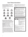 4
4
-
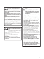 5
5
-
 6
6
-
 7
7
-
 8
8
-
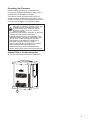 9
9
-
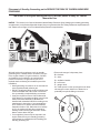 10
10
-
 11
11
-
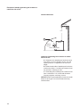 12
12
-
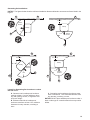 13
13
-
 14
14
-
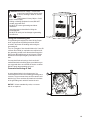 15
15
-
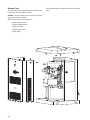 16
16
-
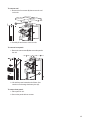 17
17
-
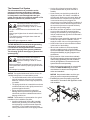 18
18
-
 19
19
-
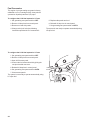 20
20
-
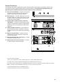 21
21
-
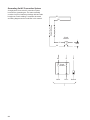 22
22
-
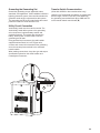 23
23
-
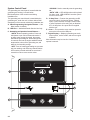 24
24
-
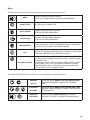 25
25
-
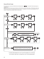 26
26
-
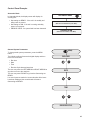 27
27
-
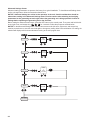 28
28
-
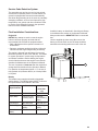 29
29
-
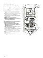 30
30
-
 31
31
-
 32
32
-
 33
33
-
 34
34
-
 35
35
-
 36
36
-
 37
37
-
 38
38
-
 39
39
-
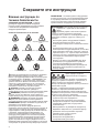 40
40
-
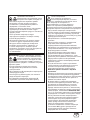 41
41
-
 42
42
-
 43
43
-
 44
44
-
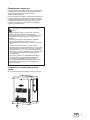 45
45
-
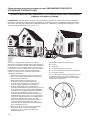 46
46
-
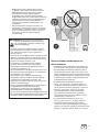 47
47
-
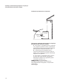 48
48
-
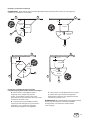 49
49
-
 50
50
-
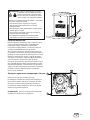 51
51
-
 52
52
-
 53
53
-
 54
54
-
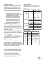 55
55
-
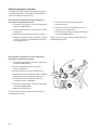 56
56
-
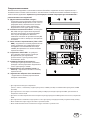 57
57
-
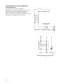 58
58
-
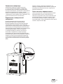 59
59
-
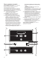 60
60
-
 61
61
-
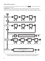 62
62
-
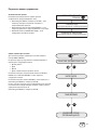 63
63
-
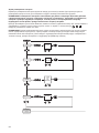 64
64
-
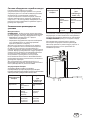 65
65
-
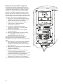 66
66
-
 67
67
-
 68
68
-
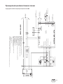 69
69
-
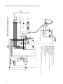 70
70
-
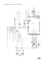 71
71
-
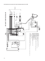 72
72
-
 73
73
-
 74
74
-
 75
75
-
 76
76
-
 77
77
-
 78
78
-
 79
79
-
 80
80
-
 81
81
-
 82
82
-
 83
83
-
 84
84
-
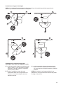 85
85
-
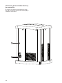 86
86
-
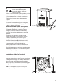 87
87
-
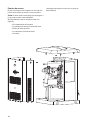 88
88
-
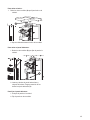 89
89
-
 90
90
-
 91
91
-
 92
92
-
 93
93
-
 94
94
-
 95
95
-
 96
96
-
 97
97
-
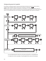 98
98
-
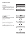 99
99
-
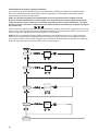 100
100
-
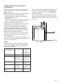 101
101
-
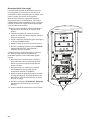 102
102
-
 103
103
-
 104
104
-
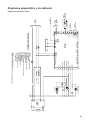 105
105
-
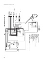 106
106
-
 107
107
-
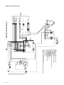 108
108


Simplicity 040494-01 Guía de instalación
- Tipo
- Guía de instalación
- Este manual también es adecuado para
En otros idiomas
Documentos relacionados
-
Simplicity 040491-00 Guía de instalación
-
-
-
-
-
-
-
-